1
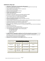
E-TON
Vector 250R
OWNER’S MANUAL
Copyright ©2008-2009 ETON America, all rights reserved.
Important Notices
READ and UNDERSTAND this owner’s manual
Both the operator and the adult supervisor should completely read and understand this
owner’s manual before operating this vehicle. This owner’s manual will instruct you in the safe
operation of the vehicle.
NO Passengers
This vehicle was designed for operation ONLY by the operator, (Driver). The load limit
and seat configuration is designed for the operator ONLY. It is not safe to carry passengers on
the vehicle.
ADULT Supervision and Instruction are REQUIRED.
This vehicle MUST NOT be operated by a youth without Adult supervision and
instructions. Unattended operation without adult supervision could result in injuries. E-TON
recommends that both the operator and the adult supervisor attend an ATV safety instruction
course.
ALWAYS Wear Protective Clothing
While operating this vehicle, the driver must always wear protective clothing. Protective
helmet with face shield, elbow and knee pads, long leg pants, gloves and hard soled boots
should always be worn when operating this vehicle.
OFF ROAD Use ONLY
This vehicle is designed and manufactured for off-road use only. Operation on public
streets, roads or highways is illegal and very dangerous.
OBEY all State and local laws and regulations
Each state and local governing agency has laws and regulations for ATV operations. It
is the owner’s responsibility to know, understand and obey these laws and regulations.
SPEED RESTRICTION Devices
This vehicle is equipped with electronic speed limiting devices. Any attempt to change,
over-ride or bypass these devices may cause dangerous operating conditions.
Age Recommendations by model size
ATV Model Size
ETON Models
Minimum Age
Weight Capacity
Under 70cc
RXL-40Ee
RXL-50M
RXL-70
6 years and older
70 Lbs
70 - 90cc
RXL-90
RXL-90R
12 years and older
250 Lbs
over 90cc
CXL-150
RXL-150R
16 years and older
250 Lbs
Over 150cc
VXL-250R
16 years and older
350Lbs
Copyright ©2008-2009 ETON America, all rights reserved.
Page 1
Table of Contents
Important Notices.................................................................................................................................... 1
Safety Notes ............................................................................................................................................ 4
Additional safety tips: ............................................................................................................................. 7
Vehicle Identification Numbers.............................................................................................................. 8
Controls, Switches & Feature Locations ................................................................................................ 8
Engine Stop Switch................................................................................................................................. 9
Manual choke lever................................................................................................................................. 9
Throttle lever........................................................................................................................................... 9
Front and Rear Brakes .......................................................................................................................... 10
Parking Brake........................................................................................................................................ 10
Fuel Tank .............................................................................................................................................. 10
Fuel Valve............................................................................................................................................. 11
Inline Fuel Filter ................................................................................................................................... 11
Engine Oil ............................................................................................................................................. 12
Oil Level Warning indicator ................................................................................................................. 12
Changing the engine oil ........................................................................................................................ 13
Engine Cooling System......................................................................................................................... 13
Checking the level................................................................................................................................. 13
Engine Coolant Mixture........................................................................................................................ 14
Coolant system leaks............................................................................................................................. 14
Transmission ......................................................................................................................................... 14
Shifting gears ........................................................................................................................................ 14
Transmission Oil................................................................................................................................... 15
Tires and Wheel inspection................................................................................................................... 15
Tire Pressure ......................................................................................................................................... 16
Spark Plug............................................................................................................................................. 16
Spark Arrestor Screen ........................................................................................................................... 16
Air Filter................................................................................................................................................ 16
To clean the filter .................................................................................................................................. 17
Braking Systems ................................................................................................................................... 17
Front Brake System Inspection............................................................................................................. 17
Rear Brake System Inspection .............................................................................................................. 18
To Fill the Reservoir ............................................................................................................................. 19
Purging Brake Lines ............................................................................................................................. 19
Drive Chain........................................................................................................................................... 19
Drive Chain........................................................................................................................................... 20
Chain Slack Adjustment ....................................................................................................................... 20
Throttle Lever ....................................................................................................................................... 20
Adjusting the throttle cable................................................................................................................... 20
Electrical Battery .................................................................................................................................. 21
Digital Console ..................................................................................................................................... 22
ATV Break In procedures..................................................................................................................... 22
Pre-Operation Inspection procedure ..................................................................................................... 22
Starting Procedure................................................................................................................................. 22
Driving your ATV................................................................................................................................. 23
Turning your ATV ................................................................................................................................ 23
Parking Your ATV................................................................................................................................ 23
Vector 250R Specifications .................................................................................................................. 24
Copyright ©2008-2009 ETON America, all rights reserved.
Page 2
Table of Contents
Maintenance Schedule .......................................................................................................................... 26
Owners Maintenance Records .............................................................................................................. 26
Warranty ............................................................................................................................................... 27
Warranty ............................................................................................................................................... 28
Owner’s Notes: ..................................................................................................................................... 30
Copyright ©2008-2009 ETON America, all rights reserved.
Page 3
Safety Notes
1. Both the adult supervisor and youth operator must fully understand everything in this manual
before operating this vehicle.
2. This vehicle was designed for the operator only. NO PASSENGERS should be allowed on
this vehicle.
3. This vehicle is designed for operation on level, obstacle free off-road areas.
4. Riding this vehicle on public roads or highways is illegal. If it becomes necessary to cross a
public road or highway, the vehicle should be pushed across using extreme caution.
5. This vehicle MUST NOT be operated without adult supervision and instruction.
6. DO NOT operate this vehicle while under the influence of drugs, alcohol or other medication
that impairs judgment or coordination. Doing so can result in serious injury or even death.
7. Maintain a safe distance between your vehicle
and other vehicles with whom you are riding.
8. READ the owner’s manual carefully before
riding.
9. ALWAYS wear a helmet, face shield, elbow &
knee pads, hard-soled boots, gloves, and protective
clothing while operating this vehicle.
Copyright ©2008-2009 ETON America, all rights reserved.
Page 4
10. NEVER ride this vehicle unless it has
been properly maintained and adjusted.
Always perform a pre-ride inspection of your
vehicle. Look for wires, bolts and other
fasteners that may have come loose on
previous rides. Inspect the drive chain,
throttle and brakes for proper adjustment and
operation. Check the engine oil level in the oil
tank. Check fuel level and inspect for fuel
leaks. (Remember, you can ride further in 1
hour than you can walk back in 1 day!)
11. WARM UP your body with some exercises
before riding. This helps to make you alert and
prevent cramping and other discomfort.
12. LEARN TO RIDE this vehicle properly and
safely. Have an experienced rider teach you the
safe operation of your vehicle. E-TON
recommends you take an ATV riding course
before you first ride your vehicle.
Copyright ©2008-2009 ETON America, all rights reserved.
Page 5
13. NEVER REFUEL this vehicle when hot. Ask
your adult supervisor to refuel your vehicle.
Gasoline is extremely flammable and will ignite if
spilled on a hot engine or muffler. Never smoke
or expose the fuel to an open flame or spark
while refueling your vehicle. Always refuel your
vehicle in a safe place free of any ignition source.
14. NEVER run the vehicle in an enclosed area. The
exhaust gases from the engine contain CARBON
MONOXIDE which can be fatal if breathed in high
concentrations for an extended time.
15. HOT! The engine and exhaust system on
your vehicle become very hot during normal
operation. Touching these hot surfaces can
cause severe burns. Always assume that your
unit’s engine and exhaust system are HOT
unless you know that they are not.
Copyright ©2008-2009 ETON America, all rights reserved.
Page 6
Additional safety tips:
•
•
•
•
•
•
•
•
•
•
•
•
•
•
•
•
•
•
•
•
•
•
•
•
•
•
•
Participate in an approved ATV safety education training program
Always provide responsible adult supervision for ATV operators younger than 18 years of age
Don't let youngsters ride full-sized ATV's
Follow all safety recommendations of the ATV manufacturer
Operate ATVs only during daylight
Wear a helmet with face protection at all times
Operate only four-wheeled ATVs
Provide a drug and alcohol free environment
Always use the buddy system
Avoid riding in areas where contact with automobiles might be possible
Drive ATVs on surfaces as recommended by the manufacturer
Travel at speeds conducive to conditions and operator abilities
Check on the conditions of the trails you will be traveling
Know and understand local and state laws governing the use of ATVs
Permit only one operator per ATV
Insist on a "perfect fit" between the ATV and the physical, mental, and emotional maturity of the operator
Use antenna flags and wear bright clothing to increase conspicuity.
Use maps and compass if you are riding in an unfamiliar area.
Make a mental note of landmarks; you may need them if you are stranded.
If you are lost at night, do not move around. You will waste valuable fuel that you can use to ride safety in
the daylight.
Carry a first-aid pack with you.
Carry some snacks and a water supply with you.
Carry equipment to handle medical and mechanical emergencies.
Your vehicle field repair kit should include the following items;
o the manufacturer's tool kit
o wire, tape, elastic cords,
o possibly locking pliers
o and a tow rope.
Pre-Ride Inspection - Inspecting the condition of your ATV before each ride is very important to minimize
the chance of injury and maximize the enjoyment of your ride. It also helps ensures long term
performance of your ATV. Follow the owner’s manual guide to inspection and maintenance of your ATV.
A well maintained ATV will give you years of enjoyment.
Watch out for thin ice which may be camouflaged by snow.
Remember, you can ride further in one hour than you can walk in an entire day.
Age Recommendations by model size
ATV Model Size
ETON Models
Minimum Age
Weight Capacity
Under 70cc
RXL-40Ee
RXL-50M
RXL-70
6 years and older
70 Lbs
70 - 90cc
RXL-90
RXL-90R
12 years and older
250 Lbs
over 90cc
CXL-150
RXL-150R
16 years and older
250 Lbs
Over 150cc
VXL-250R
16 years and older
350Lbs
Copyright ©2008-2009 ETON America, all rights reserved.
Page 7
Vehicle Identification Numbers
Your VIN RFZ______________ Eng. No._______________
Vehicle Identification Number (VIN)
is located at the front of the unit under
the front fender on a plate mounted
between the main frame rails.
Engine serial number
is located on the left-hand side of the
engine on the crankcase housing.
Controls, Switches & Feature Locations
Locations of controls and features
1.
2.
3.
4.
5.
6.
Main Switch
Fuel Tank Cap
Parking Brake Lever
Throttle Lever
Front Brake Lever
Speedometer / Odometer
Fuel Gauge
Headlight indicator
7. Engine Stop switch
8. Starter Button
9. Headlight switch
Copyright ©2008-2009 ETON America, all rights reserved.
10. Horn Button
11. Manual Choke Lever
12. 12v DC Accessory outlet
13. Transmission Selector indicators
14. Gear Shift Lever
15. Cooling Radiator
16. Engine Oil Dipstick
17. Rear Brake Petal
Page 8
Control Features
Engine Stop Switch
Throttle lever
The stop switch is a red colored rocker switch
located on the left-hand handle bar.
To start and run the engine, this switch must
be placed in the on, “Ω”, position.
The throttle lever is located on the right-hand
handle bar below the grip. To operate the throttle
lever, place your right thumb on the lever and
press forward to increase your speed. To
decrease your speed, reduce your pressure on
the lever and the spring tension will
The vehicle is also equipped with a safety
brake switch which will prevent the engine
from starting until the parking brake is
engaged.
To stop your engine, place the switch to the
stop, “8”, position.
In the stop, “8”, position the ignition system is
grounded preventing the spark plug from
firing.
This switch can also be used as a safety or
emergency stop switch.
automatically reduce your speed.
Manual choke lever
The travel of the throttle lever is controlled by the
throttle stop bolt.
All Vector is equipped with a manually
operated carburetor choke system. This
choke is operated by the lever at the bottom
of the left hand control switch.
When first starting the engine,(cold start),
place the lever in the full left position, (Choke
closed or on). As the engine warms return
the lever to the full right position. (Choke open
or off).
Copyright ©2008-2009 ETON America, all rights reserved.
As your operator gains more experience, you
can increase the throttle travel to allow for
additional speed to be obtained.
To increase the throttle’s travel, thus increasing
the maximum speed, turn the throttle stop bolt
counter clockwise. To decrease the throttle’s
travel, thus decreasing the maximum speed, turn
the throttle stop bolt clockwise.
Page 9
The throttle cable should be adjusted so there
is 2mm, (1/8”) free travel at the lever before
the throttle starts to open.
Front and Rear Brakes
This vehicle is equipped with dual front
hydraulic Disc brakes and a rear hydraulic
disc brake
Fuel Tank
The front brakes are controlled by the long
brake lever on the right-handle bar.
The rear brake is controlled by foot peddle
located in the right foot well of the unit.
The rear brake is the primary stopping brake
on your vehicle. Using the rear brake to stop
your vehicle will prevent steering control loss.
Use your front and rear brakes in combination
to control your speed while descending a
grade. Use caution not to apply too much
pressure to your front brakes so that the
wheels lock up, stop turning, and causing a
loss of steering control. If the front wheels
lock up, and stop turning, lightly reduce the
pressure on the front brake lever until they
unlock and start to turn.
Parking Brake
The front brake, shown in the picture below, is
located on the right hand side of the handle
bar. The parking brake is engaged by moving
the lever to the right and disengaged when by
moving the leer to the left.
The parking brake should be engaged when
ever the unit is not in operation and when
starting the unit.
Copyright ©2008-2009 ETON America, all rights reserved.
The fuel tank fill
cap is located on
top of the unit just
ahead of the seat.
The cap contains
a vent to prevent a
vacuum from
forming in the tank
as fuel is used.
The vent tube
must be attached
to the cap and
inserted in the
vent tube holder
hole while operating the unit. The fuel cap vent
and vent tube must be clean and clear of
obstructions for the unit to operate normally. You
can check the vent and vent tube by blowing air
through the tube. If you can not blow through the
vent tube and cap you must clean the vent and
tube or replace them.
Every time you refuel your unit, check the rubber
seal inside the cap for cuts, tears and dirt. Clean
or replace the seal if it becomes worn or torn.
The seal must be in good condition to insure a
proper seal of the cap to the tank to prevent fuel
spills. DO NOT allow dirt or other debris to enter
the tank when refueling.
Replace the cap if damaged or if it will not seal
to the tank.
Page 10
Tighten the cap snugly, being careful not to
over tighten. Over tightening the cap can
cause damage to the cap or seal.
The fuel tank capacity is 12 liters, 3.17 gal,
including a reserve of 2.5 liters, 0.66 gal.
Use unleaded automobile gasoline with an
octane level of 89 or higher.
NEVER REFUEL YOUR ATV when the
engine is HOT. Wait 30 minutes after
turning off the unit before refueling. Spilling
fuel on a HOT engine could cause a fire.
Wipe up any fuel spills before re-starting.
Fuel Valve
The unit is equipped with a three way fuel
valve located on the left side of the unit just
below the seat.
ALWAYS CHECK YOUR Fuel level before you
start riding your ATV.
Remember: You can drive further in one hour on
your ATV than you can walk in one day.
The “PRI” position of the valve allows fuel to flow
freely from the tank bypassing the vacuum valve.
The “PRI” setting is primarily use when draining
the fuel from the tank for long storage periods or
during vehicle maintenance. It can also be used
in an emergency if the vacuum valve fails to
operate correctly allowing the unit to be taken to
a place where the fuel valve can be serviced.
DO NOT operate the vehicle with the valve in the
“PRI” position for long periods of time.
Inline Fuel Filter
Your ATV is equipped with an inline fuel filter to
prevent dirt and debris from entering the
carburetor and engine.
The valve has three settings; “PRI”, “ON” and
“RES”. With the valve in the “ON” or “RES”
position fuel flow is controlled by a vacuum
vale in the petcock. Fuel will begin flowing to
the carburetor as soon as the engine is turned
over. “ON” is the normal operation position of
the fuel valve. When you have to switch to the
“RES” position you must refuel the unit as
soon as possible to prevent running out of
fuel.
Copyright ©2008-2009 ETON America, all rights reserved.
Check the filter for dirt or damage before each
ride and at each refueling. Replace the filter if
dirty or damaged.
The filter should be replaced every 600 hours of
operation and at the start of each season.
To replace the filter, first turn the fuel valve to the
“ON” or “RES” position. Then carefully unscrew
the filter bowl from the bottom of the fuel vale by
Page 11
turning the bowl counter clockwise. Remove
the old filter by pulling down on the filter to
disengage the pressure fitting from the mount.
Install the new filter by pressing up until the
filter snaps in place over the mount and re
install the filter bowl by turning clockwise until
it is hand tight. Turn the fuel valve to the “PRI’
position to fill the filter bowl with fuel and
check for leaks.
Return the fuel valve to the normal “ON”
operating position.
Inspect the fuel lines running from the tank to
the fuel valve and the line running from the
valve to the carburetor. Replace any line that
shows signs of wear or cracking and any line
that is leaking fuel.
DO NOT start or operate the engine if the fuel
filter or lines are leaking. Leaking fuel can
cause a fire.
Engine Oil
The engine oil dip stick is located on the
right side of the unit and can be accessed
through the cutout in the footrest side guard.
To check the oil level remove the dipstick by
turning counter clockwise until it is
completely free of the engine case. The level
of oil can be gauged by the level indicated
on the dipstick. The level should be
maintained between the low and high
indicators on the dipstick. If the oil level is
low add enough additional oil, SAE 10W-30,
to return the level to a safe position. DO
NOT over fill the engine oil level as this can
cause engine damage or failure.
Always check your engine oil level with the
engine off and in a cool state. Checking the
oil level while the engine is hot can give a
false reading. Removing the Oil level dipstick
with the engine running may allow hot
engine oil to splash from the crankcase
causing burns.
The engines oil capacity is 1.2 Liters / 1.2
Quarts. E-TON recommends an automotive
oil grade of SAE 10W-30 be used.
Oil Level Warning indicator
The unit is also equipped with an oil level
indicator located in the lower left hand corner
digital console display. The lamp will light when
the oil level in the engine is low. When the lamp
is lit you MUST STOP the engine and refill the
engine oil reserve to a safe level.
DO NOT allow the engine to operate with an
empty oil tank. Doing so will result in
extensive damage to your engine. This
damage is not covered under the warranty.
Checking the engine oil level
Your ATV uses an automotive type engine oil
to lubricate and cool the engine. It is
important to maintain a proper oil level to
prevent damage and/or failure of the engine.
Copyright ©2008-2009 ETON America, all rights reserved.
Check the engine oil level before each riding
session and at each refueling operation.
Page 12
Changing the engine oil
The engine oil requires changing every
1800Mi / 3000KM and at the start of each
riding season to protect the engine.
The following steps should be followed
when changing the engine oil.
1. Place a oil catch pan directly below
the engine crankcase.
2. Remove the crankcase drain plug
located on the bottom of the crankcase
on the underside of the unit.
3. Remove the engine oil dipstick
located on the right hand side of the
crankcase directly below the
transmission shift lever.
4. Allow the oil to drain completely (1530min).
5. Reinstall the crankcase drain plug
and torque to 7-10lb-ft.
6. Fill the crankcase with SAE10W-30
automotive grade engine oil through the
dipstick hole. 1.2 liters / 1.2 quarts.
7. Reinstall the engine oil dipstick and
finger tighten
8. Dispose of used oil at a proper
recycling station as required by law.
Engine Cooling System
The Vector engine is a liquid jacketed cooled
engine. Cooling is accomplished by
Copyright ©2008-2009 ETON America, all rights reserved.
circulating liquid coolant from the engine coolant
jacket through a radiator located at the front of
the unit. If is very important to keep the radiator
fins clean and free of debris and mud to prevent
engine overheating which can cause engine
damage or failure. You need to routinely clean
the radiator by using a pressurized spray of water.
Maintaining the coolant level is also a very
important process to ensure proper engine
cooling. The coolant level should be checked
before each riding session and the coolant
replaced at the beginning of each riding season.
Proper maintenance of the cooling system will
prevent the engine from overheating and freezing.
Coolant should be change every 2 years.
Checking the level
With the unit parked on level ground, remove the
front grill cover and check that the coolant level
in the reserve tank is between the upper and
lower limit indicator lines. If the coolant level is
near or below the lower limit add coolant to raise
the coolant level to the upper limit indicator line.
Coolant should be a mixture of distilled water
and anti-freeze.
CAUTION: Add coolant through the reserve
tank. The coolant system runs under pressure.
Page 13
Removing the radiator cap while the coolant
system is hot can cause over boiling and
serious burns or other injuries
season for signs of deterioration such as cracking
of checking of the hose surface. Replace cooling
system hoses at least every 3 years.
Transmission
Engine Coolant Mixture
The engine coolant should be a mixture of
distilled water and anti-freeze solution with a
specification rating of H68.
The following chart will help you determine
the correct water to anti-freeze ratio.
Operating
Anti-freeze solution
temperature
percentage
32° to -8° F
20%
-9° to -15°F
30%
-16° to -24°F
40%
-36° to -45°F
50%
Your unit was shipped with a 50% solution.
Coolant system leaks
If your coolant system is consistently low on
coolant there in most likely a leak in the
system. Start the unit and allow it to run until
it has reached it operating temperature. Check
the coolant system radiator and hoses for leaks
and repair or replace as needed. Inspect
cooling system hose at the beginning of each
Shifting gears
The Vector 250 is equipped with a fully
automatic C.V.T. transmission and has a forward
and reverse gearing system. The transmission
shift lever is located of your unit just below and
ahead to the seat. The shifter has a three position
notched locator plate indicating transmission gear
selections of “F”, “N” and “R”
“F” = Forward
“N” = Neutral
“R” = Reverse
The position of the transmission gears is also
indicated on the digital console directly below
the digital readout display. It contains the same
three indicators of “F”, “N”, and “R”.
To start your engine, both the shift selector lever
and the shift indicator lamp on the console must
be in the “N”, neutral, position.
To shift from one gear to another, bring the unit
to a complete stop and while applying either the
rear or front brake slowly move the shift selector
lever to the desired gear pausing slightly in the
neutral position to allow for the transmission
gears to synchronize. One the shift is completed
Copyright ©2008-2009 ETON America, all rights reserved.
Page 14
lightly apply pressure to the throttle until you
feel the unit shift and the indicator light
confirms the shift has been completed.
If the brakes are not fully applied while
shifting the transmission the engine will stop
running.
Transmission Oil
every 3000Km / 1800 Mi or at the beginning of
each riding season which ever come first.
The following steps should be followed when
changing the transmission oil.
1. Place a oil catch pan directly below
the transmission case.
2. Remove the transmission drain plug
located on the bottom of the
transmission case on the underside of
the unit.
3. Remove the transmission filer plug
located on the upper right hand side
of the transmission case above the
transmission shifting linkage rod.
4. Allow the oil to drain completely (1530min).
5. Reinstall the transmission drain plug
and torque to 7-10lb-ft.
6. Fill the transmission case with
SAE85W-140 automotive grade gear
oil through the filler hole. 650cc / 22oz.
7. Reinstall the transmission filler hole
plug and torque to 2-3Lb-ft.
8. Dispose of used oil at a proper
recycling station as required by law
Tires and Wheel inspection
The Vector 250 requires SAE85W-140 gear
oil to lubricate and cool the transmission and
drive gears. Transmission oil level should be
checked before each riding session and change
Copyright ©2008-2009 ETON America, all rights reserved.
It is important to inspect your tires and wheels
for damage and wear before each riding session.
Inspect each tire for cuts, tears and punctures.
Inspect the wheel rim for dents and separation of
the wheel from the tire bead.
Page 15
Replace any tire or wheel found to be
damaged.
Operating your ATV with damaged tires or
wheels is dangerous. Damaged tires or
wheels can result in a sudden loss of tire
pressure and control which could result in
injuries.
Check your tire pressure before each riding
session and at each refueling operation.
Always check the pressure when the tires are
cool. Use the tire pressure gauge that came
with your ATV to check the tire pressure.
Tire Pressure
Recommended tire pressures are:
Min
3.2psi / 0.23kg/cm
Front
Max 4.0psi / 0.28kg/cm
Min
3.2psi / 0.23kg/cm
Rear
Max 4.0psi / 0.28kg/cm
Wheel Nut torque 24-30 N/m (18-22 lb/ft)
Spark Plug
Set the spark plug gap on the new plug to 0.023”
Install the new plug screwing it in finger tight and
then use the plug wrench to screw the plug in
another ½ turn.
Inspect the spark plug wire for cuts, nicks or
other damage. Replace as needed.
Spark Arrestor Screen
Required maintenance and cleanout:
1. After every 1800Mi / 6000Km of
operation the muffler should be cleaned
by removing the clean out bolt by using a
12mm wrench.
2. After every 1800Mi / 6000Km of
operation the Spark Arrester has to be
cleaned by loosening the retaining nut
using a 10mm socket. Using pliers turn
the sleeve of the Spark Arrester
counterclockwise and pull out. Clean the
screen with an exhaust cleaning solution
and replace, securing it by tightening the
retaining nut.
3. After every 2 years of operation the
Spark Arrester has to be replaced by
loosening the retaining nut using a 10mm
socket or wrench. Using pliers turn the
sleeve of the Spark Arrester
counterclockwise and pull out. Replace a
new Spark Arrester and secure it by
tightening the retaining nut.
Air Filter
Air Filter Maintenance
Replace spark plug at the beginning of each
season with a replacement plug
NGK – CR8E.
Disconnect spark plug wire.
Clean dirt from around spark plug base with
brush or air.
Remove spark plug with spark plug wrench.
Copyright ©2008-2009 ETON America, all rights reserved.
Page 16
5. Soak the element in clean engine oil until
completely saturated.
6. Squeeze out the excess oil until the
element does not drip any oil.
7. Allow the element to dry then reinstall the
element and cover.
Braking Systems
Your ATV unit is equipped with dual front hydraulic
disc brakes and a single rear hydraulic disc brake.
The front brakes are applied by applying pressure
to the brake lever located on the right-handle bar,
while the rear brake is applied by applying
pressure to the foot peddle located in the right
hand foot rest area.
To maintain the highest performance from your
engine and to reduce excessive wear that could
cause engine failure the engine requires a
continuous flow of clean air. Air is taken into the
engine through an air filter to clean the air prior
to mixing it with fuel and oil in the carburetor.
During normal operation the filter
accumulates dirt from the air and will need to
be cleaned to maintain the proper air flow.
The filter should be cleaned every 30 days,
more often if you ride in a dusty or dirty
environment and the element should be
replaced every year.
Proper maintenance of the brake system is a
necessary part of safe operation of your unit. The
brake systems should be inspected and tested
before each riding session.
Front Brake System Inspection
Visually inspect the brake lines for any signs of wear.
Inspect the lines for cracks and checking of surface
that could lead to line rupture. Replace all
questionable lines before operating your unit. Check
the fluid level in the master brake cylinder to insure
that the fluid is at least covering ¾ of the site glass.
Add brake fluid as needed.
The air filter box is located on the left side of the
engine under the front fender. It is a black box
about 6” square and is attached to the
crankcase with two bolts and the carburetor by
a tube.
To clean the filter
1. Remove the air filter box cover.
2. Remove the filter element from the air
box.
3. Wash the element in a non-flammable
solvent such as Air-Filter cleaner from
your local auto parts dealer.
4. Dry the element completely before
continuing.
Copyright ©2008-2009 ETON America, all rights reserved.
Page 17
Brake fluid Dot-3 SAE-J1703 grade.
Inspect brake line joints and wheel cylinders for
leaks and repair as needed.
Rear Brake System Inspection
Apply the brakes by squeezing the brake lever.
The level should stop with the brakes fully apply
and at least ½” / 13mm of clearance between the
brake lever and the handle bar grip. It there is
less than ½” / 13mm clearance or the lever is not
firm the brake pads may require changing. Or the
line may need bleeding.
Insect the brake pads for wear and be sure they
are clean and free of dirt and mud. Brake pad
service limit is 0.06” / 1.5mm thick. Replace pads
that are at or below the service limit.
Inspect the brake rotor for cracks and warp.
Replace defective rotor as required.
The brakes are equipped with a wear indicator to
alert you when your brake shoes need replacing.
Apply light pressure to the brake lever and slowly
push the unit forward. If you hear a high pitched
metallic scraping sound, you need to replace your
brake shoes. The minimum shoe lining thickness
is 1.5mm.
DO NOT RIDE A UNIT WITH WORN
BRAKE PADS or DAMAGED ROTOR.
Copyright ©2008-2009 ETON America, all rights reserved.
Visually inspect the brake hose for any signs of wear
or leaks.
Check the fluid level in the fluid reservoir by
checking the site glass for the level.
The fluid Reservoir should be at least ¾ full when
the unit is setting on a level surface.
Test the brakes by applying pressure to the brake
pedal and trying to push the unit forward. If the
wheel rotates while the brakes are applied, check
your fluid level and brake pads. If the brake pedal
feels spongy or does not stop when squeezed, you
Page 18
may have air in the lines. All air must be purged
from the brake lines for the disc brake to operate
properly.
Purging Brake Lines
For the hydraulic brake system to operate safely, the
After riding your unit, be sure to clean any build
up of mud, sand and dirt from the brake rotor skid
plate. This will protect the rotor disc from rust and
corrosion.
To Fill the Reservoir
Remove the reservoir cover by removing the two
cover bolts.
Fill the reservoir to 1/8” from top with Dot-3 SAEJ1703 grade brake fluid.
Caution: DO NOT allow dirt to fall into the
reservoir.
Refold the cover gasket as shown in picture and
replace cover and bolts
Copyright ©2008-2009 ETON America, all rights reserved.
brake system must be purged of air in the lines and
reservoir.
To bleed the air will require two people to perform
the following procedure.
1. Place a drain pan under the brake caliper to
catch the fluid.
2. Open the bleeder valve ½ turn counter
clockwise.
3. Press the brake pedal to expel air from the
system.
4. While holding the brake pedal, close the
bleeder valve.
5. Repeat steps 2 through 4 until the brake fluid
coming from the bleeder valve is a solid
stream without any air, then close the valve
and replace rubber protection cap.
6. Test the brake system by pressing the pedal,
the pedal should feel firm and stop without
fading.
Page 19
Drive Chain
The drive chain will stretch with use and will
require periodic adjustments. To check the chain
tension, remove the chain guard and measure the
slack.
The amount of slack in the chain should not
exceed 10-20mm or ¼” - ½”.
Inspect the drive and axle sprockets for worn,
damaged or broken teeth. Replace as needed.
Inspect the chain links for damaged, worn or
loose rivets. Repair or replace as needed.
hours of operation, or more frequently if needed,
with a high quality chain lubricant.
Throttle Lever
The throttle lever is located beside the righthandlebar grip and is operated by using the righthand thumb. The lever is spring loaded and will
return to the idle position when you remove your
thumb from the lever. To accelerate the unit, simply
press the lever forward to open the throttle slide in
the carburetor. To slow the unit, reduce the pressure
on the lever or remove your thumb and the throttle
will return to the idle position automatically.
Chain Slack Adjustment
Loosen the axle position lock bolt slightly and turn
the chain adjuster nut to take up the excess slack
in the chain. Once the chain has been adjusted
to the proper tension retighten the axle position
locking bolt.
The chain should be kept well lubricated to
prevent excess wear and premature failure. We
recommend that you lubricate the chain every 15
Copyright ©2008-2009 ETON America, all rights reserved.
Adjusting the throttle cable
Page 20
The cable should be adjusted to allow for ⅛” free
travel before the throttle engages the carburetor
throttle slide. To adjust the cable’s free travel,
loosen the locking nut of the cable adjuster, and
turn the adjuster wheel until there is ⅛” free travel
When reinstalling the battery, be sure to connect the
red cable to the positive (+) terminal and the black
cable to the negative (-) terminal.
The battery should be replaced every three years or
when it no longer holds a charge.
in the lever. Tighten the locking nut to secure the
adjusting ring.
The speed of the unit can be adjusted by
adjusting the throttle stop screw to limit throttle
travel. Loosen the throttle stop screw locking
nut and turn the throttle stop screw clockwise to
reduce the throttle travel thus reducing the
maximum speed of the unit. Turning the stop
screw counter clockwise will increase the
throttle travel thus increasing the maximum
speed of the unit. Tighten the stop screw
locking nut when the desired throttle travel has
been established.
Do not expose the battery, for extended periods of
time, to freezing temperatures. If the battery has
been frozen it will need to be replaced. There is an
inline fuse on the positive lead of the battery to
protect the wiring system from over loads. If your
starter motor will not turn over and the battery is fully
charged, check the inline fuse on the unit.
If your starter motor will not turn over and the battery
is fully charged check the inline fuses
NOTE: Your unit includes an electronic speed
control that is set to limit the maximum speed of
the unit to the standards set by the CPSC for
the age of the rider the unit was designed for.
Electrical Battery
The unit’s battery is located under the seat and
supplies electrical power to the unit. The battery
is a 12 volt jell acid type that contains no liquid
electrolyte. The battery should be removed from
the vehicle when stored for extended periods
and charged before being replaced in the unit.
Use a trickle charger set at 12 volts to recharge
the battery to full charge before replacing it in
the unit.
Copyright ©2008-2009 ETON America, all rights reserved.
Page 21
Digital Console
The Vector 250 is equipped with a digital
console which displays information about the
operating conditions of your ATV.
1. For the first two weeks of operation do
not run your ATV at full throttle for
extended periods of time.
2. Your first tank of fuel should be a premixture of fuel and oil at a 50:1 ratio. This
will insure that the oil pump system has
been primed and bled of air that may
have occurred in shipping.
3. Do not operate the unit at more than 85%
of maximum speed.
4. Do not over rev the engine.
5. Use light braking pressure to allow the
brake pads to seat to the rotor and drums.
Pre-Operation Inspection
procedure
The following procedure must be performed
before each operating session.
Information displayed are;
1. Speedometer
2. Odometer
3. Fuel level
4. Transmission gear position
5. Hi-Beam Indicator
6. Oil Level WARNING!
7. Engine Temperature WARNING!
When you first turn the ignition key on all
the indicator should illuminate as a test of
the LED If an LED fails to light when the
ignition key is first turned on you should
replace the console assembly.
The console has two buttons. The left hand
button will reset the oil level warning lamp
and the right hand button will zero the trip
odometer.
ATV Break In procedures
Your ATV requires a break in period just as
with all other internal combustion engines.
This period allows the engine parts to seat
and wear properly without undue strain which
can cause premature failure.
Copyright ©2008-2009 ETON America, all rights reserved.
Checking your ATV takes only a few minutes
and may save you from serious injuries and
costly repairs.
1. Check engine oil level.
2. Check engine fuel level.
3. Check brake operations and brake fluid
Level.
4. Check tire condition and pressure.
5. Check drive chain condition and slack.
6. Check throttle operation and free play
adjustment.
7. Check engine stop switch for proper
operation.
8. Check steering system. Look for free and
smooth operation. Check all fastening
hardware.
9. Check all nuts, bolts and other fasteners
for loose conditions.
10. Inspect unit for any broken or damaged
parts.
11. Check all indicator lights and switches for
proper operation.
12. Insure you are wearing proper clothing
and protective gear. Helmet, Gloves
Pads etc.
Starting Procedure
The following procedure must be followed
each time you start your unit.
Page 22
Park the unit on a level surface and lock the
parking brake.
Place the transmission gear selector switch in
the “N”, Neutral, position.
Insert the key into the ignition switch and turn
to the “ON” position.
Turn the engine stop switch to the “ON”
position.
Set the manual choke lever to the full left
position (Choke close or on)
Apply front or rear brakes.
Apply slight pressure to the throttle lever.
Press the starter button on the left-handle bar.
Your unit should start within 10 seconds of
pushing the starter button. If the unit fails to
start check the following.
1. Engine stop switch is “ON”.
2. Parking Brake Locked “ON”.
3. Transmission selector switch in the “N”
position.
4. Set the manual choke lever to the full
left position (Choke close or on)
throttle to allow the rear wheels to turn properly.
When making a turn, the wheels on the outside
of the turn must travel a wider radius and thus a
greater distance than the inside wheels of the
turn. Since the rear axle does not permit a
different rate of rotation, it is not enough to
merely steer your ATV into the turn.
To turn properly, steer in the direction of the turn
and lean your body to the inside of the turn while
supporting your weight on the outer footrest. Use
the throttle to maintain power throughout the turn.
If you do not use this turning technique the unit
will have a tendency to continue in a straight line.
If this occurs, release the throttle lever to allow
the unit to stop.
Avoid braking or accelerating until you have
regained directional control.
Parking Your ATV
Driving your ATV
Your ATV should only be driven in an area
that is designated for this use. Insure that the
area is free of obstacles and other dangers
that could cause a loss of control. Check with
your local authorities for any regulations
regarding the use of your ATV.
Always keep your feet on the footrests and
your hands on the handle bar grips while
operating your ATV. Doing so will give you
the best control of the unit.
1. Always park your ATV on a level surface.
2. Turn the ignition key to the “OFF’”
position to stop the engine.
3. Set the engine stop switch to “OFF”
position.
4. Engage the parking brake locking button.
5. Turn the fuel valve to the “OFF” position.
6. Remove the ignition key to prevent
unauthorized use or theft of your ATV.
Start your ATV by following the starting
procedure above and allow the engine a few
minutes to warm up before releasing the
parking brake.
Start the unit by slowly increasing the throttle
until the unit begins moving.
Turning your ATV
Learning to turn your ATV requires you to
learn to shift your weight and control the
Copyright ©2008-2009 ETON America, all rights reserved.
Page 23
Vector 250R Specifications
Engine
Type
Displacement
Bore / Stroke
Compression Ratio / Pressure
Torque / BHP
Four cycle , Single Cylinder, Liquid cooled
249cc
φ71mm * 63mm
10.6 : 1
22.3Nm @ 5500rpm / 16.4bhp
Meet or exceeds EPA clean air requirements/CA Green
Sticker
Electrical starter
EPA Approved
Starting
Transmission
Type
Automatic (C.V.T. V-Belt) Manual Shift Fwr/Rev
Chassis
Overall Length
Overall Width
Overall High
Wheel Base
Seat Height
Ground Clearance
Dry Weight
1780mm / 70.1"
1030mm / 40.6"
1140mm / 44.9"
1190mm / 46.9"
890mm / 35.0"
150mm / 5.9"
200kg / 441lbs
Suspension
Front
Rear
Dual A-arm Adjustable Shocks @ 2.95" travel
Swing Arm Adjustable Shock @ 4.72" travel
Brakes
Front
Rear
Hydraulic Disc (2)
Hydraulic Disc
Tires
Front
Rear
Front
Tire Pressure
Rear
Min
Max
Min
Max
21/7-10
22/11-9
3.2psi / 0.23kg/cm2
4.0psi / 0.28kg/cm2
3.2psi / 0.23kg/cm2
4.0psi / 0.28kg/cm2
Wheels
Bolt Pattern
Carburetor
Make/Size
Main Jet
Pilot Jet
Air Mixture Adjustment
Idle Speed
Copyright ©2008-2009 ETON America, all rights reserved.
Kei-Hin with Manual choke
1.1mm
0.35mm
Back out 1 - 2½turns
Idle 1600 - 1800rpm
Page 24
Sprockets
Front
Rear
Chain
520x15t
520x38t
#520*90 O-Ring
Battery
Jell Acid (Maintenance Free)
12V-9AH - GTX12-BS
Fluids
Type
Volume
Type
Volume
Type
Volume
Fuel
Engine Oil
Transmission
Unleaded Gasoline 89 octane
12liters / 3.17gal
SAE 10-30W
1.4liters / 1.4gt (1.2liters / 1.2qt for change)
SAE 85/140 weight gear Oil
750cc / 25.4oz (650cc / 22oz for change)
Spark Plug
NGK
NGK-CR8E
Electrode Gap
0.6-0.7mm / 0.023"
Carrying Capacity
Front
Rear
Towing
Trailer Wgh
Capacity
Tongue Wgh
Maximum Rider Weight
Minimum Rider Age
Rack Capacity
Available Colors
N/A
16kg / 301lb (Optional)
330kg / 727lb (Optional)
50kg / 110lbs
150kg / 330lbs
16 years
Red
Blue
*subject to availability
Copyright ©2008-2009 ETON America, all rights reserved.
Page 25
Maintenance
Schedule
Fuel Line
Throttle Operation
Air Filter system &
Element
Spark Plug
Carburetor Idle Speed
Drive Chain
Brake Shoe Wear
Brake System
Nut, Bolt, Fastener
Wheels & Wheel Nuts
Steering System
Suspension System
Waste Gas Recovery
Valve
Intake & Exhaust Valve
Adj.
Gear & Engine Oil
INITIAL
SERVICE
(First week)
REGULAR SERVICE
I
I
I
C
(Every 30 operating
days)
I
I
R
I
I
I, L
I
I
I
I
I
I
I
I
I, L
I
I
I
I
EVERY
YEAR
R
I
I
I
I
I
I
I
I
R
I
I
R
Note –
I: Inspect and Clean, Adjust, Lubricate, or Replace (if necessary)
C: Clean
L: Lubricate
R: Replace
NOTE: E-TON recommends that all maintenance and
inspections be performed ONLY by a qualified and fully
trained technician!
Owners Maintenance Records
Maintenance Performed
Copyright ©2008-2009 ETON America, all rights reserved.
Date
Page 26
Performed By
Vector 250R Wire diagram
Copyright ©2008-2009 ETON America, all rights reserved.
Page 27
Warranty
ETON AMERICA, LLC.
LIMITED VEHICLE WARRANTY
ETON America warrants all new ETON vehicles sold by authorized Eton Dealers to be free
from defects in materials and workmanship, subject to the following exclusions and
limitations. New vehicles sold by an authorized dealer to original retail consumers are covered
by this policy for a period of six (6) months from the date of delivery. There is no mileage
limitation.
Vehicles used in rental service or for certain commercial purposes are specifically excluded
from this policy. (Check with your dealer for warranty application.)
Items and conditions that are specifically excluded from this warranty program are;
1. Damage caused by accidents, misuse, negligence, improper vehicle operation.
2. Any modification or alteration to any standard specifications or equipment.
3. Any repairs made by an unauthorized dealer or service firm.
4. Use of non-ETON genuine parts for repairs or alteration to standard specifications.
5. Damage caused by failure to perform factory scheduled service maintenance.
6. Damage which occurs as a result of improper storage.
7. Damage caused by the use of improper fuel or lubricants, and/or failure to use proper
oil/gas mixture on two stroke models.
The following normal wear parts are specifically excluded from warranty coverage:
1. Rubber parts
2. Tires
3. Belts
4. Brake linings
5. Normal wear item
6. Brake parts
7. Cables
8. Filters
9. Spark plugs
10. Bulbs
11. Batteries
12. Sprockets
13. External springs
14. Seat and hand grips.
Copyright ©2008-2009 ETON America, all rights reserved.
Page 28
ETON AMERICA, LLC.
LIMITED VEHICLE WARRANTY
Scheduled maintenance service is the responsibility of the owner during and
after the warranty period. In the event of a failure or required repair, the owner should take
vehicle to an authorized dealer for repair without undue delay and within a maximum of thirty,
(30), days of the occurrence of the problem. All eligible warranty repairs must be made at any
authorized dealer’s normal place of business. Any transportation costs, or other expenses
which may occur in order to obtain warranty service, are the responsibility of the owner. All
eligible repairs covered under this warranty will be paid to the servicing dealer only, by ETON
America, and no additional payments shall be made for authorized warranty repairs.
Dealer and/or ETON America are not responsible for loss of use, other damage or
inconvenience due to warranty repairs. It is the customer/buyer’s responsibility to review with
the selling dealer the pre-delivery service schedule to assure machine is properly serviced prior
to delivery acceptance. It is recommended that the buyer take a test ride to familiarize
themselves with the machine and to make certain the unit is in proper operating condition. The
dealer is responsible for checking and performing all items on the “set-up and pre-delivery
checklist” prior to delivery to the customer.
This warranty is valid at any authorized ETON Dealer in the United States only. In the event
you experience any problem obtaining prompt service, contact ETON America, customer
service department for assistance. Always consult first with your selling dealer and or service
personnel for assistance with any service work or repairs. In the event you have a problem
obtaining service send your name, address, and vehicle identification number to Eton America
for assistance.
The above stated policy is the only policy offered and backed by ETON America, and no other
organization or individual is authorized to make or offer any different arrangements. Some
states prohibit certain limitations or conditions or do not allow exclusions or limitations. You
may be eligible for additional consideration, so check with your local dealer or appropriate
state agency for assistance. Rights vary from state to state, and you may have other rights not
offered in this warranty.
ETON America warrants all new vehicles comply with applicable US regulations.
Copyright ©2008-2009 ETON America, all rights reserved.
Page 29
Owner’s Notes:
Copyright ©2008-2009 ETON America, all rights reserved.
Page 30
ETON AMERICA, LLC.
LIMITED VEHICLE WARRANTY
ETON America warrants all new ETON vehicles sold by authorized ETON Dealers to be free from defects in materials and workmanship,
subject to the following exclusions and limitations. New vehicles sold by an authorized dealer to original retail consumers are covered by this
policy for a period of six (6) months from the date of delivery. There is no mileage limitation. This warranty is given to the original retail
purchaser and is non-transferrable.
Vehicles used in rental service or for certain commercial purposes are specifically excluded from this policy. (Check with your dealer for
warranty application.)
Items and conditions that are specifically excluded from this warranty program are;
8.
Damage caused by accidents, misuse, negligence, improper vehicle operation,
9.
Any modification or alteration to any standard specifications or equipment.
10. Any repairs made by an unauthorized dealer or service firm,
11. Use of non-ETON genuine parts for repairs or alteration to standard specifications.
12. Damage caused by failure to perform factory scheduled service-maintenance.
13. Damage which occurs as a result of improper storage.
14. Damage caused by the use of improper fuel or lubricants, and/or failure to use proper oil/gas mixture on two stroke models.
The following normal wear parts are specifically excluded from warranty coverage:
15. Rubber parts
16. Tires
17. Belts
18. Brake linings (after 30 days)
19. Normal wear item
20. Brake parts
21. Cables
22. Filters
23. Spark plugs
24. Bulbs
25. Batteries (after 30 days)
26. Sprockets
27. External springs
28. Seat and hand grips.
Scheduled maintenance service is the responsibility of the owner during and after the warranty period. In the event of a failure or required
repair, the owner should take vehicle to an authorized dealer for repair without undue delay and within a maximum of thirty, (30), days of the
occurrence of the problem. All eligible warranty repairs must be made at any authorized dealer’s normal place of business. Any transportation
costs, or other expenses which may occur in order to obtain warranty service, are the responsibility of the owner. All eligible repairs covered
under this warranty will be paid to the servicing dealer only, by ETON America, and no additional payments shall be made for authorized
warranty repairs.
Dealer and/or ETON America are not responsible for loss of use, other damage or inconvenience due to warranty repairs. It is the
customer/buyer’s responsibility to review with the selling dealer the pre-delivery service schedule to assure machine is properly serviced prior
to delivery acceptance. It is recommended that the buyer take a test ride to familiarize themselves with the machine and to make certain the
unit is in proper operating condition. The dealer is responsible for checking and performing all items on the “set-up and pre-delivery checklist”
prior to delivery to the customer.
This warranty is valid at any authorized ETON Dealer in the United States only. In the event you experience any problem obtaining prompt
service, contact ETON America, customer service department for assistance. Always consult first with your selling dealer and or service
personnel for assistance with any service work or repairs. In the event you have a problem obtaining service send your name, address, and
vehicle identification number to Eton America for assistance.
The above stated policy is the only policy offered and backed by ETON America, and no other organization or individual is authorized to
make or offer any different arrangements. Some states prohibit certain limitations or conditions or do not allow exclusions or limitations. You
may be eligible for additional consideration, so check with your local dealer or appropriate state agency for assistance. Rights vary from state
to state, and you may have other rights not offered in this warranty.
ETON America warrants all new vehicles comply with applicable US regulations.
Copyright ©2008-2009 ETON America, all rights reserved.
Page 31
ETON AMERICA, LLC.
LIMITED VEHICLE WARRANTY
LIMITATIONS. This Limited Vehicle Warranty shall not cover any of the following:
Repairs or replacement required as a result of (i) accident, (ii) misuse or neglect, (iii) lack of reasonable and proper maintenance, (iv) repairs
improperly performed or replacement improperly installed, (v) use of replacement parts or
accessories not conforming to ETON America LLC specifications which adversely affect
1)
2)
3)
performance and/or durability, (vi) alterations or modifications not recommended or approved in writing by ETON America LLC,
and/or (vii) use in competitive racing or related events.
Replacement of parts and other services and adjustments required for routine maintenance.
Any vehicle on which odometer mileage has been changed so that the actual mileage cannot be determined.
LIMITED LIABILITY.
The liability of ETON America LLC under this Limited Vehicle Warranty is limited solely to the remedying of the defects in the materials or
workmanship by any authorized ETON America LLC vehicle dealer at its place of business during customary business hours. Please refer to
ETON America LLC website: www.etonamerica.com . This warranty does not cover inconvenience or loss of use of the Scooter/moped
vehicle, or transportation of the Scooter/moped vehicle to or from the ETON America LLC authorized dealer. ETON America LLC SHALL
NOT BE LIABLE FOR AANY OTHER EXPENSE, LOSS OR DAMMAGE, WHETHER DIRECT, INCIDENTAL, CONSEQUENTIAL OR
EXEMPLARY ARRISING IN CONNECTION WITH THE SALE OR USE OF OR INABILITY TO USE THE ETON America LLC
SCOOTER/MOPED VEHICLE FOR ANY PURPOSE, SOME STATES DO NOT ALLOW THE EXCLUTION OR LIMITATION OF ANY
INCEDENTAL OR CONSEQUENTAL DAMAGES, SO THE ABOVE LIMITATION OR EXCLUSION MAY NOT APPLY TO YOU.
Copyright ©2008-2009 ETON America, all rights reserved.
Page 32
ETON America LLC ATV LIMITED WARRANTY
FEDERAL EMMISSION CONTROL SYSTEMS
ETON America LLC warrants each new Scooter/moped vehicle that includes as standard equipment a taillight and a stoplight;
a) Is designed, built and equipped so as to conform at the time of initial retail purchase with all applicable regulation of the United
States Environmental Protection Agency (“US EPA”) and:
b) Is free from defects in material and workmanship which would cause such Scooter/moped vehicle to fail to conform with
applicable regulations of the US EPA, for a time period of two and a half (2.5) years and, depending on the engine displacement:
This warranty period shall begin on the date the Scooter/moped vehicle is delivered to the initial retail purchaser, or on the date the
Scooter/moped vehicle is placed in service as demonstrator, rental, lease, or company Scooter/moped vehicle prior to retail sale.
4)
COVERAGE. Warranty defects shall be remedied during customary business hours at any authorized ETON America LLC
Scooter/moped dealer located within the United States in compliance with the Clean Air Act and applicable regulation of the US
EPA. Any part or parts replaced under this warranty shall become the property of ETON America LLC.
5)
OWNERS OBLIGATION. The following obligations must be fulfilled by the owner to maintain the validity of the ETON America
LLC Emission Control System Warranty:
a) Owner must deliver the Scooter/moped vehicle to an authorized ETON America LLC Scooter/moped vehicle dealer or
equally qualified service facility for inspection, maintenance service and adjustments according to the Periodic
maintenance chart provided as part of, or supplemental to the Owner’s manual. Optionally, the Owner may perform this
maintenance only if it is within the scope o f the Owner’s technical and practical ability, keeping in mind some
maintenance operations may require special tools or technical expertise beyond the scope of the average Owner. In any
event, the inspection, maintenance and adjustments are to be performed at the Owner’s expense.
b) Owner must present a copy of the proof of initial retail purchase date, issued at the time of purchase to an authorized
ETON America LLC Scooter/moped vehicle dealer at the time warranty repairs are performed on the Scooter/moped
vehicle. You may also be required to show that you have performed the required maintenance which is related to the
alleged defect, so you should have detail receipts indicating that the required periodic maintenance has been performed
in accordance with the periodic maintenance chart in your Owner’s manual.
6)
LIMITATIONS. This Emission Control System Warranty shall not cover any of the following:
a) Repairs or replacement required as a result of (i) accident, (ii) misuse or neglect, (iii) lack of reasonable and proper
maintenance, (iv) repairs improperly performed or replacement improperly installed, (v) use of replacement parts or
accessories not conforming to ETON America LLC specifications which adversely affect performance and/or durability,
(vi) alterations or modifications not recommended or approved in writing by ETON America LLC, and/or (vii) use in
competitive racing or related events.
b) Replacement of parts and other services and adjustments required for routine maintenance.
c) Any Scooter/moped vehicle on which odometer mileage has been changed so that the actual mileage cannot be
determined.
7)
LIMITED LIABILITY.
a) The liability of ETON America LLC under this Emission Control System Warranty is limited solely to the remedying of
the defects in the materials or workmanship by any authorized ETON America LLC Scooter/moped vehicle dealer at its
place of business during customary business hours. Please refer to ETON America LLC website:
www.etonamerica.com . This warranty does not cover inconvenience or loss of use of the Scooter/moped vehicle, or
transportation of the Scooter/moped vehicle to or from the ETON America LLC authorized dealer. ETON America LLC
SHALL NOT BE LIABLE FOR AANY OTHER EXPENSE, LOSS OR DAMMAGE, WHETHER DIRECT,
INCIDENTAL, CONSEQUENTIAL OR EXEMPLARY ARRISING IN CONNECTION WITH THE SALE OR USE
OF OR INABILITY TO USE THE ETON America LLC SCOOTER/MOPED VEHICLE FOR ANY PURPOSE,
SOME STATES DO NOT ALLOW THE EXCLUTION OR LIMITATION OF ANY INCEDENTAL OR
CONSEQUENTAL DAMAGES, SO THE ABOVE LIMITATION OR EXCLUSION MAY NOT APPLY TO YOU.
Copyright ©2008-2009 ETON America, all rights reserved.
Page 33
Copyright ©2008-2009 ETON America, all rights reserved.
Page 34