1
"
38'
Series Boats
's Manual
Table
of Contents
,
1. Introduction ...... . . . ...... . .. '. . . . . . . . . 1-1
2. Specifications and General Layout .........
um 2-1
or
F
s
3. Controls and Indicators ..................
er .com 3-1
n
w um
O
s
r . ... 4-1
4. Principles of Operation s........
er rsFo. .....
i
ru ne
C
w. ......... . ..... 5-1
5. Getting Underway
m . . .....
O
o
s
r
r
f ise
d
e
u Services ........ . .... 6-1
6. PeriodicadChecks rand
C
.
o
nl ww
w
for Extended Lay-Up . .. ... .. . .. .. 7-1
7. DStorage
o //w
:
p
htt
Maintenance . .. .. . .. ..... . .... .. 8-1
8. General
9. Accessory Items ... . ...... . .............. 9-1
10. Troubleshooting ....................... 10-1
®
L
um
r
o
sF om
r
e
n m.c
w
sO oru
r
e
is ersF
u
r
C wn
m
fro isersO
d
de .Cru
a
o
nl ww
w
Do p://w
htt
,
)
Section 1 - Introduction
WELCOMEABOARD .. . ............. .............. . ...... 1·2
SKIPPER'S KIT ................. ....... ... . ...... ......... 1·3
um
r
o
sF.... ,o......
WARRANlY INFORMATION ..... . .. . ...e....
r
m 1·5
c
n
Dealership Responsibilities .....................
.. ...
.. • .. .. 1-5
.
w
Your Responsibilities ..................
... ............
1-5
O
um . .....
s
r
r
o
Warranty Service ...............•.................•....
.... 1-5
e
F
s
rui ners
C
m sOw
o
r
f iser
d
de .Cru
a
o
nl ww
w
Do p://w
htt
Owner's Manual, 3 Ring Binder ., ........ • .................. 1-3
Owner's Manuals, Envelopes ................................ 1-4
)
)
I-I
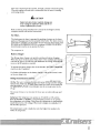
WELCOME ABOARD!!
Welcome to the Cruistar Incorporated family of happy boat owners.
First off, we wish to thank you for making our 38' Aft Cabin your recreational choice for boating enjoymenL Extensive design and engineering
research went into the development of the 38' Aft Cabin; and we feel that
there is a beautiful balance between structural integrity and creature
comforts.
You should know that your boat was manufactured by trained craftsmen
in the tradition of meeting or exceeding existing safety and quality standards established by the U. S. Coast Guard and the Boating Industry of
um
r
o
sF oboats
r
m for over 35 years.
Cruistar Incorporated has been manufacturing
e
c
n
.
We take pride in our craftsmanship
hull
We are confiwyou,and
m performance.
O
u
dent you will enjoy the ride.
For
the
Cruistar
Incorporated
is
s
r
r will Fhold
o its value while providing name
eboat
your assurance that your
many
s
s
i
r made a commitment to this industry
years of boating pleasure.
ru Wenehave
C
and are gladm
to have youw
as a partner.
O
o
s
r
r
f isone your choice - let us know if we can be of further
Congratulations
d
e
d .Cru
service.
a
o
nl ww
w
Do p://w
htt
America.
)
)
1-2
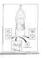
SKIPPER'S KIT
)
The skipper's kit contains the 38' Aft Cabin owner's manual bound in a
three ring binder. Along \vilh th e binder there is either one or two enve-
lopes which hold information about onboard systems and components
furnished by suppliers other than Cruisers Incorporated.
Owner's Manual, 38' Aft Cabin (3 Ring Binder)
Spend some lime looking through this manual. It contains infonnation
concerning the operation and care of your hoaL The descriptions con-
tained within the manual will introduce you to the features of the boat.
and provide you with a general knowledge of how the equipment works.
The manual is divided into ten sections. and each section is introduced by
a table of contents to help you quickly find needed information. Become
familiar with the material in each section before operating your boat
Throughout the manual you will come across safety precautions labeled
A WARNING or A CAUTION. WARNINGS indicate hazards or unsafe
practices which could result in personal io~ury or death. CAUTIONS indicate situations which could result in damage to th e boat and its various
systems.
Section I contains a description of the skipper's kit and information about
the warranty.
um
r
o
the locations of various components.
sF om
r
e
n m.c
the
Section 3 contains descriptions of all the controls and indicators onw
dash of the bridge command station and lower station helm (optional).
sO oru
r
e
is ersF
u
Section 4 contains principles of operation for the m,yor
systems onboard
r
n
the 38' Aft Cabin. Look in this section for electrical C
schematics.
w
m
o ersO
frthe
Section 5 contains inslructions for operating
boat.
d
is The section begins
e
u
with safety information which is "must"
reading.
d
r
oa w.C
l
n
Section 6 contains maintenance
w for services that need to be
w instructions
performed on a regular
Dobasis.p://w
Section 7 contains instructions
htt for storing the boat for extended periods of
Section 2 contains boat specifications such as dimensions and capacities.
There are also layout diagrams to introduce you to floorplans as well as
)
time, and prep instructions for after storage.
Section 8 contains information about the care of your boat, and how to
repair minor damage.
Section 9 contains information about the standard and optional accessory
items which complement your new Cruisers boat.
Section 10 contains a btief troubleshooting section.
)
1-3
Owner's Manuals and Pamphlets, Systems and Components
[Envelope(s)]
Spend some time becoming familiar with all the information contained in
the envelope(s), because this information is not duplicated in your Mt
)
Cabin Owner's Manual. Besides containing separate warranty informa-
tion, the envelope(s) contain manuals and pamphlets which provide
important safety, operating, and maintenance instructions
fOT
those sys-
tems and components not manufactured by Cruistar Inc. Depending on
the options you chose, the envelope may contain some or all of the following manuals:
• Engine Operation/ Maintenance (Gas or Diesel)
-Electrical schematic
• GeneralOr Operation/ Maintenance (Gas or Diesel)
-Electrical schematics
-Sen'ice centers directory
•
•
•
•
RACOR Fuel FilterlWater Separator (Diesel)
Halon Fireboy Pamphlet
AC/ DC Panel Information Packet
Refrigerator/ Freezer User Guide
• Miuowave User Manual
• Electric Stove and Oven Manual
• Trim
Plal1e~
Manual
•
I-Iydralllir.: Steering Manual
•
•
•
•
•
•
•
AC powered Ballery Charger Manual
Hot Water Heater Manual
Electric Marine Toilet Manual
Electric Anchor Windlass Operation/Maintenance Manual
Air Conditioner Information Packet
Stereo Equipment Operation Manual(s)
Compass Owner's Handbook
•
•
•
•
•
•
Beverage Dispenser User Guide
ColTee Maker/Blender User Manual
Forward and Mt Staterooms TV, with Remote Control, Owner's Manual
Trash Compactor Owner's Manual
Vacuum System, Control User Guide
Washer/ Dryer Owner's Manual
um
r
o
sF om
r
e
n m.c
w
sO oru
r
e
sF
is Guide
• TV Ante nna Instruction
r
u
e
r
• Carbon Monoxide
C (CO)wnDetector Handbook (Gas only)
Owner's Manual
• Color lVm
ro Manual
rsO
• VCRfOwner's
e
d
s
i Guide
• e
!cemaker u
User
r
•d Macerator
Pump
a
C
. DetectorOperation
lo • GaswFume
Manual
n
w /w
• w
Federal Requirements for Recreational Boats Pamphlet
o
D p:/ • Insurance Questionaire
Gel Coat Order Form
htt •• Cnlisers
Personal Accessories and Wearables Brochure
)
1-4
WARRAN1Y INFORMATION
)
Warranties for onboard systems and components furnished by suppliers
other than Cruistar are located in the envelope(s) inside the skipper's kit
Your Cruistar Dealer will go through these with you. It is your responsibility to fill out any warranty registration that may be required.
The warranty provided by Cruistar Inc. is printed on the last page of this
manual. You and the Cruistar Dealership have certain responsibilities to
fulfill to keep the warranty in force.
Dealership Responsibilities
I. The dealer will discuss the terms of all warranties, and stress the
importance of registering warranties with the appropriate
manufacturers.
2. The dealer will provide instruction for obtaining warranty service.
3. The dealer will go over the predelivery service record with you, and
then sign it to certify that all work has been accomplished.
4. The dealer will provide you with a thorough instruction in the operation of YOUT hoat and all its systems.
Your Responsibilities
um
r
o
F m
lope inside the skipper's kiL Keep a record of the hull number for ers
n m.co
future reference.
w
sO oru
r
Inspect the boat at the time of delivery to ensure that all
systems are
e
is ersF
operating properly.
u
r
C wn
m
Sit down with the dealer and go over theo
record.
r predelivery
rsOservice
fbeen
Sign this record to indicate that it has
explained
to you.
e
d
s
e
ui
d
r
a
C
Operate all equipment perlo
the manufacturer's
instructions.
.
w
n
w
ow that
wyou refer to your engine warranty for
Cruistar Inc. recommends
/requirements.
D
/
:
initial inspection and service
ttp
h
Perfonn or provide for the appropriate periodic maintenance outlined
I. Sit down with the dealer and go over all warranties. Fill in the
Cruistar limited warranty registration card which is located in an enve-
)
2.
3.
4.
5.
6.
in the owner's manuals and service guides.
Warranty Service
You are entitled to all the benefits and selVices set down in the warranties.
If a problem arises with your Cruisers boat as a result of workmanship or
materials, contact your Cruistar Incorporated dealer as soon as possible.
Please have your hull identification number, and necessary model
numbers on hand for the items that may need service or repair. Your hull
identification number is located below the rub rail on the starboard side
of the transom.
)
1-5
um
r
o
sF om
r
e
n m.c
w
sO oru
r
e
is ersF
u
r
C wn
m
fro isersO
d
de .Cru
a
o
nl ww
w
Do p://w
htt
)
)
r ')
Section 2 - Specifications and Layout
SPECIFICATIONS .......... ....... ..... . .. . .. . ........... 2-2
)
Dimensions ................ . ..... . ........•.... .. . . ... .....
Displacement .........................•.•.............•....
Deadrise .......................................•...........
Freeboard ..........................................•......
Capacities . ... . ..... ..... . . .. ..... • .......... . ...... • ......
Power .....................................................
2-2
2-2
2-2
2-2
2-2
2-2
um
r
o
sF om
r
e
n m.c
w
sO oru
r
e
GENERAL lAYOUT . .....................................
2-3
is ersF
u
Belowdecks - 3850 ......................•...................
2-3
r
n
Flybridge. Deck. and CockpitC .................................
2-4
w
m
O
o
Engine Compartment
and
Bilge
Layout
....
..
........
..•.•.....
2-7
r
rs
e
Exterior Lightingd f
............................•.•....•.......
2-9
s
e
ui
d
r
a
C
.
lo
w
n
w
w
Do p://w
htt
)
.,
2-1
SPECIFICATIONS
Dimensions
)
LOA ........ .. ......•... . . . .........• ..... .•... ....... . ... . .. 39'
LOA wl pulpit ............................................... 41'6"
LWL ..... .... ................. . ........ .. .•........ 29'9" (approx)
Maximum beam at gunwale ..... ....... ..................... ... . 14'
Maximum beam at chine ............................. ... .... l\ 'I 0"
Draft .................................... . ... 3'1-112" (Gas Engine)
Height .. . ....... . ... .........•..... .• ..... 3'2-112" (Diesel Engine)
Keel to top of radar arch .................... .. ........ 16'l\-1/4"
Water to top of radar arch . .. ................... ...... ...... 14'9"
Radar arch to top of mast light .... ... ..... ...... ........... 2'112"
Bridge Clearance .. . ........ .. ......... .... .............. 16'9-112"
Displacement
Diesel (less fuel and water) .... . ...... . ...... .. ....•...... 21 ,500lbs
Gasoline (less fuel and water) .. .................. . . ...... . 20,000 Ibs
Deadrise
FWD at LWL ....... . •........... .. • .......................... 41°
AFT at Trallsom ........................ . . . ..... ..... . ........ 14°
um
r
o
FWD ....••. .. ••...•..•......•.••...•...••••. ..• . .. 5'4-112" at bow
sF om
AFT ........................................... 3'2-112" at break-in er
n m.c
shear, just before swim plate
w
sO oru
r
e
Capacities
is ersF
u
r
ntank
C each
Fuel, Twin tanks .............................. 200 gallons
w
m
Freshwater ............•.......... .... .................
o ersO100 gallons
f.r............
Waste ... . ................................
d
is 40 gallons
e
u
d
r
Power
loa w.C
n
w
ow inboards
w
Crusader twin 300 counterrotating
/
D
:/
or
p
t
t
Crusader twin 355 counterrotating
h inboards
or
Freeboard
MerCruiser twin 330 counterrotating inboards
or
MerCruiser twin 410 counterrotating inboards
or
Volvo Pellta twin 306, TAMD 61 diesel, counterrotating inboards
2-2
)
)
)
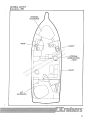
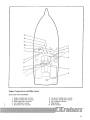
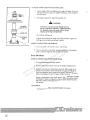
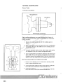
GENERAL LAYOUT
Belowdecks - 3850
um
r
o
sF om _OPTIONAL
r
e
n m.c LOWER
w
~-t......--!==-(--rr-J
STATION
O oru -J---:-: -HELM
s
r
I
ise ersF
u
r
C wn
m
fro isersO
d
de .Cru
L!_ _-SALON
a
o
l
w
n
w
w
Do p://w
htt
o
STATEROOM
)
2-3
CABIN DOOR
DECK
um
r
o
sF om
r
e
n m.c
w
sO oru
r
e
is ersF
u
r
C wn
m
o ersO
5d fr
3
is
e
u
d
r
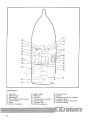
Flybridge and Deck
loa w.C
n
FLYBRIDGE
w /ww
o
D p:/
I. Single station command bridge with complete
marine instrumentation
htt
2. Bridge-to-cabin stairway
FLYBRIDGE
FLYBRIDGE
4
-~
3. Fire extinguisher
4. Wet bar
5. Flybridge lounge
I---"tus
2
)
2-4
DECK
6
)
DECK
6.
7.
8.
9.
10.
11.
um
r
o
sF om
r
e
n m.c
w
sO oru
r
e
is ersF
u
r
C wn
m
fro isersO
d
de .Cru
a
o
nl ww
w
Do p://w
htt
10
Bow hatch wl screens
Bow rope locker
Bow pulpit
Stainless steel anchor roller
Dockside phone and cable lV hook-up
Shore power hook-up
)
2-5
)
COCKPIT
um
r
o
sF om
r
e
n m.c
w
sO oru
r
e
is ersF
u
r
C wn
m
fro isersO
d
de .Cru
a
o
nl ww
w
Do p://w
htt
CfIY WATER HOOK-UP
2-6
)
9
8
I
5:---1--=:
I
10
7=
0
1=<1
~I
1
0
8Ob~\JDD~~2
m
0\ 0 ~~3
ru
o
F
s om
r
e
n m.c
4
w
O
u
s
r
ser rsFo
i
u
r,D ne
C
m sOw
o
r
r -r'--]+---3
f isO~O
e
:=---+tI~-+1
rl
:::::::::::::':1
d
de .Cru
a
o
nl ww
w
9
Do p://w
htt
1
)
D
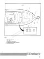
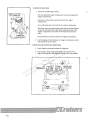
Engine Compartment and Bilge Layout
SEACOCKS AND STRAINERS
)
1.
2.
3.
4.
5.
Engine cooling water strainer
Engine cooling water seacocks
Head outlet water seacocks
Air conditioner seacock
Head inlet water seacocks
6.
7.
8.
9.
10.
Generator cooling water seacock
Generator cooling water strainer
Air conditioner sLrainer
Bilge pumps
Battery isolator
2-7
II
30
29
12
~~14
28=
27----lr--l'BDD
I
./'
~
o~1 13
26~ I ~ 0
0
_~ rum
25~
0 0
0
I Fo
s om
r
e
n m.c
w
16
O--:t:~
O oru
sR
r
18::-------L
-17
e
is ersFI
u
r
24~ m10C w- n~r--16
fro isersO
d
I
I
e
u
d
r
a
C
.
lo
w
n
w
w
Do p://w
htt
0
DO
gg
000
000
ID
20----1
0
0
:::===-:!
0 I
-i:
0
23
22
COMPONENTS
11. Generator
12. Battery charger
13. Bilge blowers
14. Air conditioner seawater pump
15. Auxiliary battery
16. Battery
17. Salon air conditioner
2-8
18.
19.
20.
21 .
Engine muiller
Waste tank
Fuel tank
Aft stateroom air conditioner
22. Trim tab pump
23. Freshwater tank
24. HALON extinguisher
25. Hot water heater
26. Engine
27.
28.
29.
30.
FOIWard stateroom air conditioner
Freshwater pump
Freshwater pressure accumulator
Generator muiller
\
'.
)
/3
2
\
1~
l
-5
y6
0
)
0
0
um
r
o
sF om
r
e
n m.c
w
sO oru
r
e
is ersF
u
r
C wn
m
Exteriorro
rsO
f Lighting
e
d
s
eI. Spotlight
ui
d
r
a
C
FWD
. mast light (International only)
lo 3.2.wAFT
n
mast light (all)
w
w
Navigation lights
Do p://w 5.4. Courtesy
lights
6. Stern light
htt
7. Boarding light
)
2·9
)
um
r
o
sF om
r
e
n m.c
w
sO oru
r
e
is ersF
u
r
C wn
m
fro isersO
d
de .Cru
a
o
nl ww
w
Do p://w
htt
)
)
Section 5 - Getting Undenvay
SAFE BOATING . ... .. .... . . ..... .. .. . ... ................. 5-2
Safety Checks ....... . .. .. . .... .. ....... .. . ... . ..... ....... 5-2
Boating Rules and Regulations .. ... ....... ....•........•.... 5-4
Safety Precautions for Engine Exhaust ..........•......... .... 5-6
um
r
o
sF... ...o..m.. 5-7
r
OPERATING INSTRUCTIONS .... ............
e
n m.c
Pre-Start Checklist ............ .. .........•.................
5-7
w
.......ru
• ......... ... 5-8
Starting Gas Engines . . ..... .. .. .. ...s...
O
r . ............
o . ... .. .... 5-9
Starting Diesel Engines .... ... ...s.e
...
F.....
s
i
r
SLOpping Gas Engines . .. .....
...
...•....
..
.... . .... .. 5-11
u
e ... . .........
r . ..n...
Stopping Diesel Engines ... C
........w
•. ... 5-11
m
O
Fueling ..... ..... .......................
.
.
•..
........
. .. 5-11
o
rs ...........• . .. .. ... .. ...
fr Techniques
Suggested Maneuvering
5-12
e
d
s
i
e
Dropping anddWeighing
Anchor
......
....
..•
......
.
..
...
...
5-16
u
r
aBoat ............................
C
.
Towing lthe
... .... .. .. ... 5-17
o
wn /www
o
D p:/
htt
)
®
5-1
SAFE BOATING
Safety Checks
)
Safe boating is one of the requirements for pleasant boating! Use common sense and safe practices while eqjoying your boat Use the following
safety checks; you are responsible for the safety of your passengers as well
as others in and on the water.
• Keep your boat and equipment in good condition; inspect the hull,
engines, power train and all gear frequently.
• Use care when fueling boat. Cas in the bilge is extremely dangerous! Make sure there are no fumes in your boat before starting the
engine.
• Know your fuel tank capacity and engines' fuel consumption. Be
sure you have enough fuel to reach your destination with adequate
reserve for course changes due to weather or other problems.
• Regularly check all safety equipment such as fire extinguishers, life
preservers, flares, horn, etc. They should be in good condition,
readily visible and easily accessed.
• Keep up-ta-date navigational charts of areas to be trdveled on-
board.
um
r
o
route; leave a float plan with someone.
sF om
r
e
n casting
.c off. Watch the weather!
• Check local weather reports
before
w
m
O winds
Be on the lookout for sstrong
ruand electrical stonns.
r
o
e
F
s
• Do not overload
ers load your boat
ruior improperly
n
C
w
mgood boat
O
• Require
o
s
r
r
f ise shoes be worn by all passengers to avoid
slipping.
d
de• Passengers
ru should be instructed how to use all safety equipment
a
C
.
o
nl ww
Each person must have a life preserver. Children and nonw
Do p://w swimmers should wear life preservers at all times.
• Don't allow passengers to ride on parts of the boat not designed for
htt
that use. Do not slore equipment or climb on the radar arch or
• Make a practice of letting someone know your travel plans and
optional hardtop.
•
IlIslrtl(" at least one passenger ill the hasics of operation and handling of your boat in case you are disabled or fall overboard.
• DO NOT use the swim platform or boarding ladder while the
engines are running. Tum engine off when swimmers or skiers are
getting in or out of the water.
• Obey all navigational rules!
• If uncertain of water depth, proceed slowly and with caution!
5-2
)
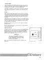
Sample Float Plan
Copy this page and fill out the copy before going boating. Leave the filled out copy with a reliable person who
can be depended upon to notify the Coast Guard. or other rescue organization. should you not return as
scheduled. DO NOT file this plan with the Coast Guard.
N;ulI(.' _ __ _ _ _ __ __ _ _ _ _ _ __ __ __
Description of Boat:
Type _ _ _ _ __
Tclt'phonc _ __ _ _ __ _ _ __ _ _ _ _ __
Trim ________
Color _ _ _ _ _ __
Registration Number _ _ _ _ _ _ _ _ _ _ _ _ _ _ _ _ _ _ _ _ _ _ _ _ _ _ _ _ _ _ _ _ _ __
Make
Name
Olher Info.
Age
Name
Persolls Aboanl:
Address & Telephone
HI' _ _ _ _ _ _ _ __
um
r
o
No. of Engines:
sF om
r
e
n m.c
Survival Equipment:
w
sO ru
I'FD's _ __ _ _ _ __ Flares _ _ _ _ _ _ _e_r Mirroro_______
_
F
s
s
i
r
u
r
ne _ Food
_ _ _ _ __
Flashlight C
Smoke Signals _ _ _ _ _ __
w
o_m_ _e_rs_O__
r
f
Water
_
Anchor
Paddles
d uis
e
d
r
Rafl or Dinghy
loa w.CEI'IRB
n
w
w
Freq _ _ _ _ _ _ _ _ _ __
Yes
Radio:
Do p:/No/w__ Type
Trip Expectations:
htt Depal1ure Time _ _ _ _ _ _ _ __ Leaving From
Engine Type:
Fuel Capacity: _ _ _ _ _ _ _ _ _ _ _ _ __
Est. Time of Arrival
Destination
EXP(Tt to Return
_~
___________
By _____________
Auto Type _ _ _ _ _ _ _ _ __
License No. _ _ _ _ _ _ _ __
Parked
lfnot returned by ______________ (all the Coast Guard, or
(Local Authority). Coast Guard Telephone Number:
Lo(al Authority Telephone Number: _______________________
)
5-3
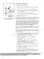
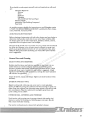
Boating Rules and Regulations
BASIC RUl.ES FOR SAFE BOATING
)
• Your hoat must he registered and licensed in the staLe of principle
use.
• Give right of way to slower boats, rowboats and sailing craft.
• Keep to the right! Observe the Danger Zone and give right of way
to boats in this zone.
• Do
110t
use your motors near swimmers or divers.
• Learn the language of the various buoys and warning signals.
2 POINTSABAFf
STBDBEAM
BOAT APPROACHING
GOVERNMENT REGULATIONS
The Coast Guard is the authority of the waterways; they are there to help
the boating public. You and your boat are subject to marine traffic laws
and "Rules of the Road" that are enforced by the Coast Guard.
There are many pamphlets, prepared by the Coast Guard, available to you.
These pamphlets explain "Rules of the Road", signal lights, buoys, safety,
international and inland regulations and more than is discussed here. For
lIIore information contact your local U. S. Coast Guard unit, U. S. Coast
Guard Headquarters, 1300 E Street NW, Washington, D.C. 20226 or call
the Coast Guard Boating Safety Hotline at 1-800-368-5647.
um
r
o
sF om
r
e
n m.c
in your area.
w
sO oru by the U. S. Coast Guard for
The minimum standards e
ofrsafety asFrequired
s MUST
your boat are listed below.
ers equip your boat to meet or exceed
rui You
n
these requiremenLc;,
C
m sOw
o
r
r Guard approved, Type I, II or III. personal flota• Atfleast oneeCoast
d
s
i
tion device
de than
ru (life jacket) for each person aboard. If you are more
a
C
20 miles offshore, you must have Type I.
.
o
w
nl w
w
• At least one Coast Guard approved, Type IV, throwable flotation
o
w
D p:// devke - ring or cushion.
htt
• At Ieasl two Type B-1 or one Type B-II hand-held fire
There are also many boating safety courses available to the public. Call
toll-free "Courseline" 1-800-336-2628 to find out what courses are offered
extillgtlisllers.
• AI I('ast Ihrec Coast (~lIard approved, hand-held red pyrotechnic
(nal "('-tYIH"') (Iislress sigllals:
Night Use -three aerial red pyrotechnic distress signals
Day Use -three international orange smoke signals
• All pyrotechnic devices must be stowed in waterproof, non-glass
cOlltainers.
• One hand. mOllth or power operated whistle or horn that can be
heard for at least onc-half mile.
• A bell with a mouth diameter of at least 7.9 inches.
The Coast Guard also recommends you carry an anchor. anchor linc,
mooring lines, fenders, first aid
electrical tape and tool kit.
ki~
waterproof flashligh~ spare fuses,
)
®
5-4
SIGNALS AND RULFS OF THE ROAD
• Learn and obsen'e the United States Weather signals. Red and black
flags are used by day and red and whitt' lights are used at night.
Small Cmf! Warning
Fon'cast is for winds lip to 3H mph (34 kllots) and/ or sea conditions dangerolls to small craft
Gale Warning
Forecast is for winds from 39 to 54 miles an hour (34 to 48 knots).
SMALLCRAFf
WARNING
$
GALE
WARNING
S
WHOLE GALE
WARNING
$
Whole Gale Warning
Forecast is for winds f)'om 55 to 7:~ miles all hour (48 to 03 knots).
HURRICANE
WARNING
Hurricane Warning
Forecast is for winds in excess of 74 miles an hour (64 knots).
• Obey marker flags.
A red flag with a diagonal white stripe, or th e "An lIag, indicates a skin
diver in the area.
A solid orange lIag with a black square atop a black ball indicates distress. Either the boat or a passenger is in serious trouble.
• Recognize the different buoys; they
There are three types of buoys:
afC
the waterway road markers.
um
r
o
sF om
r
e
n m.c
w
sofOthe oru
r
When enteting port or going upstream, the PORT (left) side
e
sF
is The
channel is marked with GREEN. ODD numbered canubuoys.
r
e
r
STARBOARD (right) side of the channel is marked
n EVEN
C with RED.
w
m
numbered nun or spar buoys.
fro isersO
d
The middle of the channel is marked
RED
de with
ru and WHITE vertically
a
C
striped spherical or ca n buoys;
always
pass
close to the buoys. Can
.
o
l
buoys will have a sphericalntopmark.ww
w
/w
Dojunctions,
/
:
Obstructions, channel
are marked with RED and GREEN
pA REDetc.band
t
at the top means the preferred
t
horizontally striped buoys.
h
channel is to the left of the buoy; a GREEN band means the preferred
NUN - Cone shape
SPHERE - Spherical shape
CAN - Cylindrical shape
channel is to the right of the buoy. These buoys arc sometimes lettered.
hut never numhered.
Lights. hells and horns are usetl
contlilions.
Oil
buoys
f()J" night
~
WARNING:
SKIN DIVER
IN AREA
~
WARNING:
SKIN DIVER
IN AREA
~
DISTRESS
nOATOR
PASSENGER
IN SERIOUS
TROUBLE
or poor visibility
• Know whistle signals!
One Long Blast: Warning Signal (Coming out of slip)
One Short Blast: Pass on my port side
Two Short Blasts: Pass on my starboard side
Three Short Blasts: Engines in reverse
Four or More Blasts: Danger Signal
~
NUN
CAN
5-5
• If there is a ship-to-shore radio telephone aboard, answer any distress
calls. "MAYDAY" is the international signal of distress. NEVER use this
word unless there is an emergency and assistance is needed
ilnnlediatcl),.
IlISClIAR(;~:
OF OIL
The discharge of oil or oily waste into or upon navigable waters of the
United States or of the contiguous zones is strictly prohibited by the Federal Water Pollution Control Act. If such a discharge occurs and causes a
film or shee n upon or discoloration of the surface of the water, or causes
an emulsion or sludge beneath the surface of the water, the violators are
subject to a penalty of $5,000. Notify the Coast Guard immediately or call
toll-free 1-800-424-8802 to report any such incident.
Safety Precautions For Engine Exhaust
A
WARNING
DO NOT inhah exhaust fumes! Exhaust contains
carbon monoxide. Carbon monoxide is colorless,
odorless and potentially kthal.
The carbon monoxide present in exhaust fumes can be extremely hazardous. Direct. prolonged exposure will cause brain damage or death. Incoherence. drowsiness, loss of consciousness, headaches. nausea and vomil~
ing are some symptoms of exposure to carbon monoxide.
um
r
o
sF om
r
e
.c
wn your
If you think exhaust fumes areO
entering
boat, correct the problem
m
s safety
ruprecautions:
immediately. Observe the following
r
o
e
F
s
• Be alert for the odor
ersfumes.
rui of exhaust
n
C
w while underway in certain wind and sea con• A natural vacuum
m created
O
o
s
r
r
ditionsf may allow
exhaust to be drawn into the cabin. Adjust the direcewhile
d
s
i
tion
of the u
boat
underway as necessary to alleviate the presence
e
d
r
a
of
exhaust
fumes.
C
.
lo
w
n
w
not
allow the boat to remain stationary with the engine running for
•
Do
w
Do p://wany extended period.
Use care when operating engines or generator in confined areas.
htt • Exhaust
fumes can enter the boat even with all windows, doors and
hatches closed.
• Never operate the generator or leave the engine running if the exhaust
pun is ohstructed.
• NEVER nm the engines or generator while everyone onboard is sleepiug. If a person is sleeping. be sure adequate fresh air ventilation is
provided.
• If your boat is equipped with a forward hatch or windshield side vents,
OPEN THEM while underway.
• Iryou choose to be underway with canvas up. you must vent the forward area LO clear the cockpit of fumes.
• Inspect the engine exhaust system frequently for tightness of clamps
and hoses. If you notice a change in engine sound, check all exhaust
COntICCliOlIS.
5-6
OPERATING INSTRUCI10NS
Pre-Start Checklist
Before starting the engines, perform the following checks and procedures:
• See Section 6-PERIODIC MAINTENANCE, Refore Every Use.
• Your craft should be securely moored to the dock or slip. The boat
should remain moored until the engines are warmed up and properly running.
• Check weather conditions and forecasts.
• Check all life saving devices. Make sure there is one life jacket for
each person aboard.
• Check capacity rating plate. Do not leave the dock with an overloaded craft!
• Open windows, doors and all floor hatches. Check for fuel fumes
and water in the bilge areas.
• Operate hilge blowers for al least four minutes before slaning
engilles. Allow the blowers to nlll ullLii cl1lising speed is attained.
um
r
o
sF om
r
Check gas fuel valves to make sure fuel can flow to engines.
e
n m.c
w
Check diesel fuel valves to make sure fuel can flow to engines.
sO oru
r
e
F
iswater, eairrsconOpen seacocks for engine cooling water, head flush
u
r
C wn
ditioning water, etc., as equipped.
m
rsO Look for
frocontrallinkage.
Check steering control, throttle and
shift
e
d
s
i
e
is tight
hydraulic leaks. Make sure all d
connecting
uhardware
r
a
C
.
o
nl ww
Check battery charge.
w
Do p://w
Check fuel supply.
htt IMPORTANT
• Check engine and transmission oil levels. If equipped, check fresh
water coolant level.
•
•
•
•
•
•
00 NOT rely on 'he a"curacy of gauges.
Readings arc only approximate and should
always be compared to the hours of use multiplied by the known fuel consumption (GPH).
• Check all electrical components such as the horn, lights, and bilge
pumps to be sure they are in proper working order.
• Make sure shift control levers are in the NEUTRAL position.
)
5-7
Starting Gas Engines
Mter pre-start checks and procedures have been followed, the engines can
be started. Follow the step-by-step instructions below, but be sure to read
the Engine Owner's Manual for manufacturer's recommendations.
A
WARNING
Always start engines with shift control levers in
neutraL Your boat is equipped with neutral safety
suntxlr£s which will not allow engines to be started
unkss shift COf.trol levers are in neutral position.
Step I.
With ignition key switches off, put both shift control levers in
neutral position.
Step 2.
Move each throttle lever forward to full throttle position and
back to idle position. Throttle linkage and cable must move
smoothly.
TRANSMISSION
INNEUfRAL
um
r
o
sF om
r
e
n m.c
w
sO oru
r
e
is ersF
u
r
C wn
m
fro isersO
d
de .Cru
a
o
nl ww
w
Do p://w
htt
Step 3.
Turn key switch of one engine to START position. Release key
immediately after engine starts. The key is spring loaded and will
return to the RUN position.
A
CAUTION
Failure to release ignition fury afkr engine starts
may damage the starter motor and drive.
Do not .perare starter continuously for more than
30 seconds. Allow starter to cool at kost 2 minutes
between starting atrempts.
5-8
In cold weather, it may be necessary to move the throttle lever
hack alld fonh ~ or 4 times while the staner is operating. This
will actuate the carburetor accelerator pump and feed more fuel
to the e ngine for starting. DO NOT move throttle lever back and
forth if the engine is wann ; this will flood the engine.
Step 4.
Operate the engine at approximately 1000 RPM and check the
oil pressure gauge. If oil pressure is not within specified range
STOP ENGINE IMMEDIATELY and detennine the cause.
Step 5.
Repeat starting procedure for the second engine.
IMPORTANT
The second engine may be difficult to hear
when it starts due to the noise of the first
engine. Observe the tachometer of the second
engine. When the RPM's 'Jump up", release
the key switch immediately.
Step 6.
Allow engines to wann up. Check water temperature gauges to be
sure water temperature remains within the specified range. If
temperature gauge reads abnonnally high, STOP ENGINE
IMMEDIATELY and detennille the cause.
Step 7.
Check engine exhausts to see that they are discharging water.
Water circulation in the engines should take place shortly after
starting.
um
r
o
sF om
r
Step 8. Inspect for any fuel, oil, water and exhaust leaks.
e
n m.c
w
sO oru
r
e
is ersF
u
r
C wn
Starting Diesel Engines
m
rsOthe engines can
fro followed,
After pre-start checks and procedures have been
e
d
s
i but be sure to read
e below,
be started. Follow the step-by-step instructions
u
d
r
a
C
the Engine Owner's Manual for manufacturer's
. recommendations.
lo
w
n
w
w /w
Do Ap:/WARNING
htt
Always start engines with shift control levers in
neutral. Your boat is equipped with neutral safety
switches which will not allow engines to be started
unless shift control levers are in neutral position.
Step 1.
With ignition key switches off, put both shift control levers in
neutral position.
Step 2.
Move throttle lever of engine to be started to approximately onehalf throttle position.
)
5-9
Step 3.
Turn key switch of engine to START position (position "Ill ").
Release key immediately after engine stans. The key is spring
loaded and will return to the RUN position.
ACAUIION
Failure to release ignition Jury aftEr engine starts
may damage the starrer motor and drive.
Do not "Perate starrer continuously for more than
30 seconds. Allow storter to cool at /east 2 minutes
between starting attempts.
Step 4.
Operate the engine at approximately 1400 RPM and check the
oil pressure gauge. If oil pressure does not rise to specified range
in 15 seconds, STOP ENGINE IMMEDIATELY and detennine
the cause.
Step 5.
Repeat starting procedure for the second engine.
IMPORTANT
um
r
o
sF om
r
e
c release
engine. When the RPM's
n 'Jump
.up",
w
m
the key switch immediately.
sO oru
r
e
is ersF
u
r
Check water temperature gauges to be
Step 6. Allow engines
n up.
C towwann
surem
water temperature
remains
within the specified range. If
O reads abnonnally
o ersgauge
rtemperature
high, STOP ENGINE
f
d
s
and
detennine
the
cause.
IMMEDIATELY
i
de .Cru
a
o
nl ww
w
Do p://w
htt
The second engine may be difficult to hear
when it statts due to the noise of the first
engine. Observe the tachometer of the second
II
5·10
Step 7.
Check engine exhausts to see that they are discharging water.
Water circulation in the engines should take place shortly after
starting.
Step 8.
Inspect for any fuel. oil. water and exhaust leaks.
Stopping Gas Engines
Step I.
Move throttle control levers to idle position.
Step 2.
Put shift control levers in neutral position.
Step 3.
Turn key switches counterclockwise to OFF position.
Stopping Diesel Engines
Step I.
Move throttle control levers to idle position.
Step 2.
Put shift control levers in neutral position.
Step 3.
Move throttle control levers forward until engine RPM is no
more than 1400 RPM. Operate engines for 5 minutes at this
speed to cool engines.
Step 4.
After cooling engines. move throttle control levers back to idle
position.
um
r
o
F m
s
r
e
Step 6. When engine rotation stops, lurn key switches counterclockwise
n m.co
w
to position "0",
sO oru
r
e
is ersF
Fueling
u
r
C wn
m
Refer to your engine owner's manual for the fuel
type
rating
sOoctane
rodealereand
r
f
may
have fuel sugrecommended for your pal1.icular engine. Your
dthe useuofisyour boat.
gestions relative to climate conditions and
e
d
r
a
C
.
o
l
n WARNING
ww
wA
o
w
D p://taken every time you fuel
All precautions must""
tt it's gasoline or diesel fueL IMwhether
your
h
sel fuel is non-explosive, but it will burn!
Step 5.
Turn engine key switches to STOP position (position "R").
boa~
Use the following precautions before fueling to avoid fire and explosion:
• Make sure your boaL is securely moo.-ed to the dock.
• Stop engines. fans. galley fires and any other device that can produce a spark or flame.
• Close all windows. doors and hatches to keep fumes from entering
the boat.
• Disembark all people not needed for fueling the boat.
• Prohibit all smoking in the area.
• Locate the nearest fire extinguisher for use if needed.
5-11
While fueling, keep the fill nozzle in contact with fill opening of the tank
to protect against any static sparks or spilling fuel.
Do not fill the tanks until fuel flows from the vents. Allow room in the
tanks for fuel expansion.
When tanks are full, close fuel openings and clean up any spilled fuel.
Wash the areas around the fuel caps and vents. Dispose of rags properly
on shore.
IMPORTANT
Spilled fuel may yellow the fiberglass gel coat
and damage accent tapes.
Open all windows, doors and hatches. Operate the bilge blowers (if your
boat is so equipped) for alleasl four minutes. Fuel fumes are heavier than
air and will sink to the lowest part ofthe boat.
Before starting the engines, check for any fumes or leaks in the bilge.
Ventilate the boat until the fumes are no longer presenL Repair any leaks
immediately.
Suggested Maneuvering Techniques
GENERAL GUIDELINES FOR MANEUVERING
um
r
o
sF om
r
e
n m.care basically useless at
• Forget the Steering Wheel!w
The rudders
sO onotherucontrol levers and leave the
slow speeds. Put yourrhands
e
steering wheel alone.
is ersF
u
r
nForces! Check the wind direction and velocCthe Outside
w
• Recognize
m
ity,frasowell as the
water currents. Use the external forces to your
rsOmaneuvering;
e
d
s
advantage
when
don't fight them.
i
e
u
d
r
.C Slowly! Give yourself time to think, react, and maneuver.
loa • w
Proceed
n
w
w
Do p://w • Have the Crew Standing By! Hands ready with fenders, boat hook
and lines can assist greatly as you approach a dock.
htt
• Practice Makes Perfect! Start in calm water with no wind and lots of
room until you get the feel for the boat and its controls.
GRADUAL TURNS AT LOW SPEED
A
WARNING
High speed, full range turns are not recommended.
The quick response of the hydraulic sreering sys/em
and the high speed may cause people and objects to
be thrown around inside or even overboard. Exercise prudence in the way your boat is handled!
A gradual turn while moving at low speed, forward
Of
reverse directions, is
best accomplished by varying propeller speed. Straight line movement is
maintained with the counterrotaLing propellers turning at the same speed.
Increasing the speed of one prop and maintaining or reducing the speed
of the other prop will tum the boat towards the slower prop.
5-12
STARBOARD TIJRN
SLOWER PROP
/
d.~
"
PORT TURN
)
<
==---
:J
=---3,-
-
-=------
-~==-=-
um
r
o
sF om
r
A WARNING
e
n m.c
w
Rudders have little or no steering control at low
rsO Foru
speeds or whEn moving in reverse. This apparent se
ui ners
"loss" of steering can cause confusion, even panic,
r
C
among novice skippers. Practice maneuvering
m KnowsOw
o
BEFORE you attempt any complexrmoves.
f iser
your boat!
d
u
de .the
rbow
areverse),
C
o
Remember when turning astern l(in
wiJI make a much
w
onnthe alenwto avoid possible collisions in
wider arc than the stern. Bew
crowded areas.
Do p://w
t
HOLDING POSITION ht
ACAUIION
Do 1101 shift frmzsm;ss;oll at engine speeds above
1000 RPM. Damage to engines or power train
could result. Momentarily pause in neutral and
allow engine to return to Ulk speed before engaging
transmission.
)
Using throttle and shift control levers to compensate for wind and water
currents allows you to maintain a relatively still position in the water. Keep
the bow pointed into the wind or curren~ if possible, by using the gradual
turning procedure above. Slow and equal speeds on both props will allow
you to maintain position with minor throule adjustments for any correction. Compensate for slight wind and water current by individually adjusting throttle levers and moving shift levers between forward and neutral.
5-13
um
r
o
sF om
r
e
n m.c
w
sO oru
r
e
is ersF
u
r
C wn TURNS
SHARP ANDm
CLOSE QUARTERS
ro ersO
fturn
A shall'
can
by putting one shift lever in forward posid
isbeinachieved
e
u
d
r
tion
and
the
other
reverse
position.
rate of the turn can be conatrolled by.Cthe rudder as well as engine The
o
l
speed.
Turning Ihe steering wheel
w
n in the
w
direction of the turn will increase the Tale of lurn .
w
Do p://w
Close quarters or "on-a-dime" turns can be used to change direction in
htt small
areas.
From the hold position procedure. move the shift leveTs: olle to reverse,
the other to forward . To advance your position and quicke n the turn,
ilHTt'ase Ihe specd 011 the 1()Jward prop. To move back frolll your position
and qukken the turn, increase the speed on the reverse prop.
PROPELLER "BURSTS" AND STOPPING
Propeller hurst is a maneuvering technique requiring fairly moder.J.le
speed (ROO- I 000 RPM) and using shift comrols only. Move shift lever of
POI1 or slarhoani engine to fOlwanJ or reverse for shan inlelvals to
maneuver the uoat into the desired position.
Slopping the hoat's forward 1Il0Vcmcllt (checking headway) usillg pro-
peUer bursts will reduce the distance required to stop. With engine speeds
equal, move both shift levers to reverse to slo w or stop forward movement.
5-14
ACCELERATE - - - - BOW RAISE'> - - - - PLANING ATTITUDE
TRIMMING THE BOAT
When the boat is accelerated fonyard. its trim angle increases causing the
bow to . . ide high and the stern low. Cominued acceleration will bring the
It"jlll angle 10 a maximulII angle ("lltlll1P"); thclI the boat will level out to
its planing auitude.
um
r
o
sF om
r
e
n m.c
w
sO oru
r
e
is ersF
u
r
A WARNING m C Own
rs
froor tIu!isbow
Do not uvertrim. TIu! boat may veer
e
d
e ronlToLru
may dig in causing you to d
loose
a
.C tabs to assist the boat up
o
l
w
When accelerating to cruising n
speed, lower
trim
w
ow attitude
w
at the stern and into a planing
quickly. As water passes under the
/
D
/
:
the
stern up. Change the angle of the
hull, it contacts the trim tabs forcing
p
trim tabs to change the rate
htoft lift; lower tabs result in faster lift.
It is important to get "over the hump" as soon as possible due to the
reduced visibility. handling and perIormance. A few seconds at full throttle should get the boat over the hump and into a planing attitude. Once
you are "over the hump" and at a comfortable plane, move throttle levers
back to 2/ 3 to 3/ 4 throttle, a more fuel efficient cruising speed.
Until YOLI become familiar with trimming your boat, move the rocker
switches in half-second illteIVais. The boat will not react immediately; it
will take a rew seconds.
Trim tabs can also be used to control uneven weight situations while
~
TABS EXTENDED,
WATER PASSE'> UNDER
HULL, HITS TABS AND
FORGFS STERN UP AND
BOW DOWN.
underway. For a heavy stern, lower trim tabs equally until a comfortable
angle is achieved. If the port or starboard is heavy, lower the trim tab on
the heavy side to a point where the boat levels out.
)
5-15
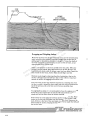
SCOPE
6T07TIMES
DEPTH OF WATER
um
r
o
Dropping and Weighing Anchor sF
r com
e
n
Maneuver the boat over the spot w
where the anchor
m. is to he lowered, keeping in mind the wind, current,sO
and scoperu
(length of the anchor line). A
erof scope
good gauge for the amount
Fisoa length 6 to 7 times the depth of
s
s
i
r
u
the water anchored rin. For example,
ne you are in 10 feel of water, so use
approximately 60 C
to 70 feetw
scope.
om ersO
r
f
bow carefully lower the anchor. When the
Have adcrew member
s on the
ibottom,
e
u
anchor
is on rthe
keep slight tension on the line. Maneuver the
d
a backwards
.C slowly until the proper scope has been fed out. Fasten the
loboat
w
n
around the bow cleat. Anchor flukes should dig in and hold.
w line
ww
Do p://Watch
for anchor drag by observing shoreline landmarks at the time the
htt anchor is dropped and one-half hour later. If the reference marks have
moved, the anchor is dragging and must be reset
The end of the anchor line should be attached to a mooring cleat. When
the line is (oiled. it should he done neatly and each coil put around or on
top of the previous coil so the line can be fed out smoothly when
anchoring.
To weigh (pull in) anchor, it is recommended to have the engines running.
Pull in the scope until the line is vertical. Pull hard to lift the anchor's
shank and free the flukes from the bottom material.
If the anchor is stuck, attach the vertical, taut line to the bow cleat Wave
action on the bow may lift flukes from the bottom. If the anchor is still
stuck, feed out a few feet of line and attach it to bow cleat. Maneuver the
boat around the anchor, keeping the line tight. Find an angle that will pull
the anchor loose.
®
5-16
If your boat is equipped with a wimIlass. use the same procedures as above
but refer to the manufacturer's instructions on the operation of the windlass. Always remember to relieve the load on the windlass when anchored;
use a bridle attached to a cleat or attach the line directly to a cleat.
Towing the Boat
A CAUTION
Do not use deck hardware for groumIing and /owing! The stress may be too much for cleats and
mounting plates. Cleats are designed for mooring
use only.
If you are aground, need a tow, or wish to low another craft, use great
care. The boat structure can be damaged by excessive pulling strain.
Use a double-braided nylon rope. Some synthetic fiber ropes stretch too
much. Make a bridle for each craft (towing and towed) by putting a rope
completely around the hull.
A WARNING
Always stay clear of any tight or stretched lines.
um
r
o
can do.
sF om
r
e
n m.c
• Wait for the rising tide to lift you off.
w
sO to oru
r
e
• Shift weight and passengers to heel of the boat. Reverse ithe
props
s
sF
r
u
back-off.
e
r
C wn
m
• Use another boat to carry the anchor to deeper
sO the
rOperate
fro water.
e
windlass to pull the boat free.
d
s
e
ui
d
r
a
C
.
the Coast Guard.
• If all efforts fail. get help fromlo
w
n
w
w /w
Do IMPORTANT
:/
p
t
t
You should always
h offer help to a craft in distress. However, towing a capsized boat.
If you run aground. depending on the situation. there are a few things you
grounded boat or hull-damaged boat is dangerous. Give assistance to the occupants, then
call the proper authorities.
r
)
5-17
um
r
o
sF om
r
e
n m.c
w
sO oru
r
e
is ersF
u
r
C wn
m
fro isersO
d
de .Cru
a
o
nl ww
w
Do p://w
htt
)
Section 6 - Periodic Checks and Seroices
PERIODIC CHECKS AND SERVICES ... . .... .. ......... . 6-2
Before Every Use .................................... .. .... 6-3
Every 50 Hours ..... . ........... .. ...... .... ............... 6-7
Every 100 Hours .....•. . ......• . ........ . .... ... ..• .. ...... 6-8
Monthly ........ . ..........................•.............. 6-9
Quarterly ................•.................. . ....... .. .•. 6-10
Annually ..... • .•... ... ..• . . ............................. 6-11
um
r
o
sF om
r
e
n m.c
w
sO oru
r
e
is ersF
u
r
C wn
m
fro isersO
d
de .Cru
a
o
nl ww
w
Do p://w
htt
)
6-1
PERIODIC CHECKS AND SERVICES
The checks and services ouLlined in this section are to be accomplished in
cOI"Uunction with the periodic maintenance outlined in the various
owner's manuals contained in the skipper's kit It is extremely important
that you read and understand the periodic maintenance tasks outlined in
your owner's manuals (such as the engine owner's manual and the generator owner's manual), because those maintenance tasks are not repeated
in this manual.
Use the table below to establish your maintenance routine. The pages
which follow provide instructions on how to accomplish each of the
required checks and services listed below.
FREQUENCY
Before Every Use
TASK
1. Check seawater strainers for leaks and accumula-
tion of debris.
2. Check exhaust system for leaks.
3. Check seacocks for leaks.
4. Check propeller stuffing box for excessive water
entry.
5. Check fuel system lines and connections for
leaks.
6. Check battery charge.
um
r
o
Every 50 Hours
1. Clean seawater strainers.
F m
sfilter.
r
2. Clean freshwater
e
co
n tie bar.
.
3. Inspect rudder
w
Orudderostuffing
um box for leaks.
4. Check
s
r
r
e propeller
5. isInspect
sF for damage.
r
u
e
r
n freshwater system for leaks.
Every 100 Hours C 1. Inspect
w
m
fro iser2.sOClean bilge.
d
Monthly
de .Cru 1. Lubricate air horn compressor.
a
o
2. Test GFCI outlet
l
w
n
3.
Check zincs.
w
w /w
Do p:/Quanerly
1. Check battery electrolyte level.
2. Check hydraulic steering system oil level.
htt
Annually
1. Check trim tab pump fluid level.
2. Check engine to shaft coupling alignment
3. Lubricate rudder shaft.
4. Lubricate seacocks.
5. Check engine mounting hardware.
6-2
)
Before Every Use
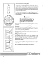
CHECK SEAWATER STRAINERS FOR LEAKS AND ACCUMULATION
OF DEBRIS
STRAINER _ _y::;::=:::@...
COVER
HOSE CONNEGrION
POINT
CONTAINER
STRAINER
1. Check the following strainers:
Pon and starboard engine cooling water strainers (Diesel or gas),
located under salon hatches in engine compartment.
um
r
o
sF om
r
e
n m.c
Air conditioning seawater strainer, located under salon floorw
hatch in engine compartment.
sO oru
r
e
ishalch einrsF
u
Deck wash down strainer, located under salon floor
r
C wn
engine compartment
m
ro the estrainers
rsO for
ffrom
Inspect all hose connections to and
d
s
e
ui
d
leakage.
r
a
C
nlo ww.the appropriate seacock to
If hose is damagedw
or leaking, close
o entry/of/w
prevent any further
D
: water, and then replace the damaged
hose and clamps. Seetp
your authorized Cruistar dealer for pans
and service.
ht
Generator cooling water strainer, localed under salon hatches in
engine compartment.
2.
3.
4. Inspect container fOT buiJd~up of debris which can clog the
strainer and cause a system failure. If strainer needs to be
cleaned, do the following:
a.
Close appropriate seacock.
h.
Remove strainer cover. Some covers can be removed by
simply loosening a wing nut and swinging the cover to the
side; others need to be unfastened using an allen tool.
c.
Lift strainer from container and use a stiff brush to clean.
Rinse with dean water, and retuTn to container.
d.
Fasten cover to container, and Temember to open seacock
before operating.
6-3
CHECK EXHAUST SYSTEM FOR LEAKS
I. Start the engines following the nomlal start procedure.
2. Check hose connections from engines and generator for leakage.
3. If leakage is apparen~ tighten hose clamps. If leakage persists.
replace hoses and clamps. See your Cruistar dealer for parts and
service.
CHECK SEACOCKS FOR LEAKS
I. Check the following seacocks:
Port and starboard engine cooling water seacocks located in the
engine compartment
Generator cooling water seacock located in the engine
compartment.
Air conditioning seacock located in the engine compartment
Head inlet water seacocks located under the aft and forward stateroom floor hatches. Head outlet water seacocks located in the
engine companment and under the fonvard stateroom floor
hatch.
um
r
o
sF om
r
e
n m.c
w
sO oru POINT
HOSErCONNECI'ION
e
is ersF
u
r
C wn
m
fro isersO
d
de .Cru
a
o
nl ww
w
Do p://w
htt
Deck washdown seacock located in the engine compartment
CHECK
FOR
LEAKS
6-4
2. Inspect hose connections at seacock for leaks.
A CAUTION
When replacing /wses, make sure that the appro-
priate seacocks are c10setL
If hose is leaking, tighten hose clamp. If hose is damaged, replace
the hose and clamps. See your Cruistar dealer for parts and
service.
3. Inspect seacocks for signs of leakage at base and handle.
A
CAUTION
Seacocks can only be replaced wken the boat is out
of the water.
If leakage is apparent, take your boat to a Cruistar dealer for
immediate service.
CHECK PROPELLER STUFFING BOX FOR EXCF$SIVE WATER ENTRY
TO
ENGINE
um
r
o
sF om
r
e
n m.c
w
sO oru
r
e
is ersF
u
r
C wn
m
fro isersO
d
de .Cru
a
o
nl ww
w
Do p:10-15
//wDROPS/ MIN AT
SPEED IS
LOCK
htt CRUISING
NUT
PERMISSIBLE
I. Operate boat at cruising speed.
2. Inspect propeller shaft at stuffing box. Ten to fifteen drops of
water per minute is nonnal.
A
)
CAUTION
Cruistar Inc. will not warrant damnge incurred
due to an impr<>J>erly adjusted or neglected packing
nut. Excessive wah!r entry could result in the submergmce of the engine compartment
6-5
3. If water entry is excessive, adjust packing gland nUL
)
ACAUIION
Always hand tighten tire packing nut. Tightening
nut roo tight will damage tire packing 7lUJkria1 and
tire shaft, ultimately leading ro system failure.
Back ofT lock nut. Hand tighten packing gland nul, and retighten
lock nUL
4. Check the ntbber coupling, it should be watertight. If leakage is
apparent, tighten hose clamps. If hose is damaged, or the leak
persists, refer the problem to your Cruisers dealer.
CHECK FUEL SYSTEM LINES AND CONNECTIONS FOR LEAKS
I. Check all lines and connections at the fuel tanks, and at the
generator and engines.
A
WARNING
DO NOT operate tire engines when fuel1eaks have
been ddecterL All fuels are combustible and gasoline vapors are explosive. Repair any leak before
starting tire engines or tire grmeratDr.
um
r
o
sF om
r
e
2. Tighten any connection thatnmay be leaking.
problem persists,
.c toIf your
w
m
or fuel lines are damaged,
refer
the
problem
Cntistar
O oru
s
r
dealer.
ise ersF
u
r
CHECK BATTERYCCHARGE n
m sOw
o
r
f iser
d
de .Cru 0
a
o
nl ww
w
Do p://w
htt
8~~\\~\\~"II""
....TTERY
lEST
1
2
OFF~3
OCVOLTS
I. Turn on DC MAIN breaker.
2. Move the battery test switch to "I" to check the starboard engine
cranking battery, and to "2" to check the port engine cranking
battery.
3. Move the test switch to "3" to check on the auxiliary batteries.
4. When you have checked all the batteries, turn the test switch to
the "OFF" position.
6-6
)
Every 50
HOUTS
~
CLEAN SEAWATER STRAINERS
Refer
10
"Check Strainers" in "Before Every Use."
CLEAN FRESHWATER FILTER
~_ FRESHWATER
FILTER
IMPORTANT
Freshwater system must be completely drained
before attempting to service filter.
:7="-':
I. Grab filter housing at bottom and unscrew fi,otn cover.
2. Remove screen from housing and flush with clean water. Use a
hrush to remove any sediment
III
1\
,~~
~~
3. Return screen to housing bOllom, and reattach bOllom to housing
coveT.
INSPECT RUDDER TIE BAR
m
COTTER
uCHECK
r
FOR
PIN
o
F LOOSEN
s
~OSENESS
r
m
ne m.co
w
sO oru
r
O~==~~==============~b
e
is ersF
CONNECTING u
r
n
C
-\ CONNECTING
ARM
w
ARM
m
O
o
fr isers
d
SETSCREW
de .Cru
~
CHECK FOR ~ECK
a
o
FORw
'=' LOOSNESSwnl LOOSENESS
w
Do p://w
CYUNDER
~
t
~
t
h
CHECK
CHECK
COTTER
PIN
Q
CHECK
FOR
TIE BAR
O 1
I
FOR
LOOSENESS
FOR
LOOSENESS
I. Check tie bar al each end for loose hardware and damaged or
missing ( Oller pins. Tighten and replace as needed.
2. Check ('ylintler where it attaches to lie bar for loose hardware.
Tighlen as needed.
3. Check cOllllecting anll at rudder shaH for looseness. Tighten as
11('('(1('(1.
4. Check nldder sh.,fL setscrew for looseness or damage. Tighten or
replace as needed.
6-7
CHECK RUDDER STUFFING BOX FOR LEAKS
I. Check mdder shaft at stuffing box for signs of leakage. Turn the
steering wheel to actuate the rudder hydraulics. There should be
110
water entry.
2. II' leakage is apparenl, adjust the packing nul
A CAUTION
PACKING
/GLANDNlIT
~
~:;;;:x:~-- LOCK NlIT
~STUFFING
BOX
Croisers Inc. will not warrant damage incurred
due 10 an improperly adjusled or neglected packiJ/g
/lut Excessive waler entry could resull in thE sub·
mergence of the engine compartment
1I'\('k olT the locking
IlUt.
Tighten the packing nut using only hand pressure. Tighten the
locking nul to secure packing nut in place.
INSPECT PROPELLERS FOR DAMAGE
J. ( :1u'ck )'H1I,cllcl"s for I)(,lllls, cnu:ks. alI(I pilling.
2. Do not continue to use badly damaged propellers. Damaged pro·
pellers must be replaced. See Section 8 for details.
um
r
o
sF om
Every 100 Hours
r
e
n m.c
w
INSPECT FRESHWATER SYSTEM
FOR
O orLEAKS
u
s
r
e
F
s
I. FiJI and pressurize
ers system.
rui freshwater
n
C
whalch to access the engine companment.
msalonsfloor
2. Remove
O
o
r
r
f ise
d
e
3.
Inspect
at freshwater reservoir, filler, pump, and
d pressure
ruconnections
a
C
accumulator.
There should be no signs of leakage. If
.
o
l
w
n
leaks are apparenl, drain system and replace defective hoses,
w
w
Do p://w tubes, and clamps. See your Cruistar dealer for pans and service.
4. Inspect connections at hot water heater. There should be no signs
htt
of leakage. If leaks are apparenl, drain system and replace defec·
tive hoses, tubes, and clamps. See your Cruistar dealer for pans
and service.
CLEAN BILGE
See Section 8, GENERAL MAINTENANCE for details.
6·8
Monthly
LUBRICATE AIR HORN COMPRESSOR
AIR HORN
um
r
o
F m
s
r
e
I. Locate hatch under fwd bridge seats, it is located directly acrossn
co
.
w
from the bridge entertainment center.
O orum
s
r
2. Open hatch and locate the compressor's oil feed tube.
ise ersF
u
r
Cof oil. wn
3. Remove feed tube cover, and add 4 to 7 drops
m
ro ersO
f
d
TEST GFCI OUTLET
is
e
u
d
r
.C power hook-up, or the
loaeitherwa shore
I. Provide AC to the boatnwith
w
onboard generator.w
Do p://w
2. Turn on the OUTLETS
OUTLETS AFT and the two OUThtt onFWD,
tlle AC master panel.
LETS breakers located
@
3. Locate the GFCI outlets throughout the boaL
4. Push the lest h1l1l011 011 each GFCI outlet. Power should be interrupted to all outlets onboard. Press the reset button to restore
power.
5. If power is not interrupted, do not use any of the outlets. Have a
qualified electrician make the necessary repairs.
@
6-9
CHECK ZINCS
TRANSOM
ZINC
A CAUTION
Failure to maintain the zincs on your boat will
result in electrolytic rorTosWn w all submerged
um
r
o
I. Check factory installed transom zinc
corrosion.
sF foroexcessive
r
m
Replace as needed.
e
n m.c
w
u
2. Check dealer installed
excessive
corrosion. Your dealer
sOzincs for
rtime
r
o
e
F
will point out their
locations
at
of delivery. Keep this outline
s
s
i
in your Skipper
ru KiL ner
C
m sOw
o
r
Quarterly
f iser
d
de BATTERY
ru ELECTROLYTE LEVEL
CHECK
a
C
.
o
nl wwSee Section 8. GENERAL MAINTENANCE for details.
w
Do p://w
htt CHECK HYDRAULIC STEERING SYSTEM OIL LEVEL
metal.
I. Remove vent plug from fill hole on helm pump.
I"
2. Visually inspect oil level. Recommended oil leveJ is approximately
'" 1'1'0111
top of fill hole.
:1. If oil needs to be added. refer to your hydraulic steering owner's
manual for filling and bleeding instructions. Use grclue of oil
recommended by manufacturer.
)
®
6-10
/
Annually
CENTER SCREW
-/---
CHECK TRIM TAli PUMP FLUID LEVEL
I. A fluid Jevelline has been added 10 the oil reservoir of the trim
tab pump. The oil level is visible through the translucent sides of
(he reservoir.
2. If oil is low, replenish jn tile following manner:
~o
---=:::::::::.:-
Remove plastic cover by unscrewing center screw.
um
r
o
sF om
r
e
n m.c
w
sO oru
r
e
is ersF
u
r
C wn
m
fro isersO
d
de .Cru
a
o
l
w
nLUbe,
wuse
w
Remove plug from
fill
and
a funnel with a tube to add
o
w
/ oil reaches
/
lubricating oil.D
Fill only :until
the full line indicated on
p
t
the reservoir.
t
LUBRICATE
h
CHECK ENGINE TO SHAFT COUPLING ALIGNMENT
See Section R, GENERAL MAINTENANCE for details.
LUBRICATE RUDDER SHAFT
c-----
SHAFf
Lubricate with a waterproof marine grease.
6-11
LUBRICATE SEACOCKS
1. Lubricate the following seacocks:
LUBRICATE WING
NUT THREADS
)
Pon and starboard engine cooling water seacocks located in the
engine compartment
Generator cooling water seacock located in the engine
companmenL
Air conditioning seacock located in the engine compartment
Head inlet water seacocks located under the aft and forward stateroom floor hatches. Head outlet water seacocks located in the
engine compartment and under the fOIW3rd stateroom floor
hatch.
Deck washdown seacock located in the engine companmenL
2. Use lubricating oil and lubricate the wing screw threads, and the
valve handle at its pivot point.
CHECK ENGINE MOUNTING HARDWARE
1. Check engine mounting hardware for looseness.
um
r
o
sF om
r
e
n m.c
w
sOo oru
r
e
is ersF
u
r
C wn
m
rsO
fro FOR
CHECK FOR
e
CHECK
d
s
i
e
LOOSENESS
u
LOOSENESS
d .Cr
a
o
nl ww
w
Do p://w
htt
2. If mounting is loose, temporarily tighten, and then have an
engine and propeller shaft alignment done as soon as possible.
--
)
6-12
Section 7 - Storage for Extended Lay-Up
STORAGE FOR EXTENDED lAY·UP ................... . 7·2
Lifting and Storing Your Boat ...... .. ..........•.•... ...... .
Transporting . . ........ . ... ... ...... . . .. . ... . . ..... .. . .....
Winterization . ... . .... ....... . . ............ • ..... .. ..... ..
Fitting Out Mter Storage .... ..• .•. ... ..... .• .. ....•. ........
um
r
o
sF om
r
e
n m.c
w
sO oru
r
e
is ersF
u
r
C wn
m
fro isersO
d
de .Cru
a
o
nl ww
w
Do p://w
htt
7-2
7-3
7-4
7-8
7-1
STORAGE FOR EXTENDED LAY-UP
Lifting and Storing Your Boat
A CAUTION
NI!Vf!T' lift a boat with a large amount of warer in
the bilge! Undue stress will be put on the 1wJl.
Slings must never contact or exert a force on sluzjls,
struts or luzrdware protruding from the ludl. This
type of stress can dJJmage fiberglass, bend or misalign parts, whkh is not covered urulEr the
warranty.
Use two web slings and 15 foot spreader bars to lift the boat Slings must
have a minimum width of six inches and a capacity rating high enough to
support the boat. Spreader bars reduce the side pressure at the boat's
sheer line and prevent distortion or damage to the deck or gunwale
molding.
Put slings around the hull at positions marked "SLING". The sling decal is
localedjuslunder the gunwale molding. Make sure the sling contacts the
bottom of the hull for the entire length with no twists in the sling.
um
r
o
sF om
r
e
n m.c
w
sO oru
r
e
SLING
is ersF
u
r
C wn
m
fro isersO
d
de .Cru
a
o
nl ww
w
Do p://w
htt
When lifting the boat, keep the bow slightly higher than the stem to keep
water from nlOning into engine manifold. Water can cause corrosion or
damage to the engine.
)
D
------------;z: ~C)~--~C)~--~C)~~~
SLING
DECAL
SLING
DECAL
.
APPROX.5'
I
TRANSOM
APPROX.11'
..
,I
AT CHINE
)
7-2
ACAUIION
When your boat is out of the water, it is important
to support the Iwll correctly to avoid any hull
damage.
Tk shipping/storage.cradle will provide the proper support at the recom·
mended positions. The load at the cradle support areas is less than 10
pounds per square inch. Make sure the cradle is level and completely supported on the ground to eliminate any cradle or hull distortion. Contact
your Cruistar Inc. dealer to order a cradle.
IT a factory·supplied cradle is not available, extreme care should be used
to support the hull as shown above. Do not support boat by resting hull on
keel; the load will be more than 10 pounds per square inch! Vertical suppons must extend from chine to keel to chine with no gaps between the
hull and cradle supports. Protect all items extending from the hull from
resting on the support or ground. DO NOT apply any load stress to props,
shafts, rudders, struts, etc.
Transporting
The boat must be supported on a trailer with the same care and concern
as on the ground. Cover the boat 10 prevent additional load being added
from rain or snow. Contact your dealer for assistance in transporting your
craft
•
•
•
•
•
um
r
o
sF om
r
e
Transporting Checklist
n m.c
w
sO tooru
Check all federal, state and local regulations and requirements
r
e
transport your boat. Arrange for any permits and escons
is asersF
u
r
required.
C wn
m
sO sparks and
ro accidental
Disconnect and remove batteries to fprevent
r
e
d
s
spilled electrolyte.
e
ui
d
r
a
C
. spilling and possible fire.
lo fuel fumes,
Empty fuel tanks to prevent
w
n
w
w /w
Dosystem
Empty freshwater
p:/to reduce transportation weight
t
t
Remove all items h
from cabinets, pockets and drawers to eliminate
damage.
• Secure all drawers, clIshions, doors, etc. to prevent any cabin damage from items moving around during transpOIt.
• Secure hatches. windows, doors and canvas to prevent damage
from wind and accidental opening.
• Cover and tie the boat down securely to avoid any shifting, tipping
or sliding during transport
7-3
Winterization
ACAVTION
If improperly sWred, the boat could take on water
which can accumulate and cause damage to onboard systems.
If your boat is to be stored on shore, a thorough winterizing procedure
will extend the life of your boat and its equipment Utilize the following
suggestions to make boat prep for the next boating season a little easier.
a.
Clean the hull and deck as soon as the boat is pulled from the
water. This will make cleaning easier because the marine growth
will stilI be wet (See the Care and Cleaning section in this
manua!.)
b.
c.
Store the boat with the bow up so any accumulation of moisture
will run off.
Inspect the hull and underwater gear for signs of deterioration,
wear or damage. Note any damages to engine. cabin equipment,
helm area, etc. that has occurred during the past boating season.
Try to have any repairs made before covering the craft
um
r
o
sF om
IMPORTANT
r
e
n m.c
w
Do not fill the tanks
so
the
uflowsforfrom
sOin thefuel
r
r
vents. Alloweroom
tanks
expansion.
o
is ersF
u
r
nbe filled with treated fuel to prevent conI. Fuel C
tanks should
w
m
the
densation.
Use
O following products per instructions on
s
rocontainer.
r
f
d Gasolineise use a stabilizer and conditioner, such as "STA-BIL".
e
u
d
r
Diesel- use a biocide, such as "BIOBOR" and conditioner,
loa w.Csuch
n
as "RAYCOR RX 100".
w
w /w
o
D p:/
2. Run engines for ten minutes to make sure treated fuel is present in all lines and parts of the engines.
htt
d.
Fuel System:
3. Operate any other engines, such as the generator which uses
the same fuel source, until treated fuel is through the engine.
e.
Engines:
I. Flush engines with clean fresh water.
2. Refer to the engine owner's manual for procedures to store
and winterize the engines.
f.
Generator Engine:
I. Flush engine with clean fresh water.
2. Refer to the engine owner's manual for procedures to slore
and winterize the engine.
7-4
)
g.
Remove the drain plug at the bottom of all exhaust muffiers to
prevent freeze damage. (This includes the generator muffier.)
Store plugs ill a safe place.
h.
Head and Holding Tank:
l. Empty and rinse holding tank with water until tank is clean.
2. Close h ead intake seacock and remove hose from seacock.
AWARNlNG
DO NOT use auimnotWe type radWor antifreeu
wuJer any circumslonces! II is poisunous. See your
marine or recreatiunaI tkakr for nun-Imrie
antifreeze.
3. Put hose into a bucket of non-toxic antifreeze. Keep flushing
the head until antifreeze reaches the holding tank.
4. If equipped with macerator discharge and the boat is
removed from the water, operate macerator pump just long
enough so antifreeze nlll5 through pump and lines.
um
r
o
Air Conditioning System:
sF om
r
e
wn um.c
l. Open intake seacock. Loosen screws on the seawaterOpump
head to allow water to drain from pump.
ers rsFor
s
i
ru ne
2. Disconnect intake and both unit supplyC
hoses.
m sOw
o
r
r with clean water.
3. Flush units and lines to strainer
f and seacock
e
d
s
i
u
de low.Cairrpressure.
4. Blow water out of lines
with
a
o
l
ww
wnfrom/wboth
condensing units.
5. Disconnect o
hoses
D p:/
6. Close air conditioning
htt intake seacock.
5. Remove drain plug from seacock while seacock is closed.
Allow line to drain. Replace drain plug.
i.
)
7. Remove drain plugs from seacock and strainer. Allow to drain
and replace drain plugs.
J.
Deck Wash System:
1. Close intake seacock and remove intake hose.
2. Put hose in a bucket of non-toxic antifreeze. Operate system
until antifreeze solution is discharged from system.
3. Turn system off and relieve pressure in hose, if connected.
4. Remove drain plug from deck wash seacock. Allow to drain
and replace drain plug.
)
7-5
k.
Freshwater System:
I. Turn the water heater circuit breaker to OFF.
2. Remove the freshwater supply by opening the hot and cold
faucets in the galley for 10 minute intervals. Repeat the procedure until the freshwater tank is empty.
3. Turn the freshwater pump circuit breaker to OFF.
4. Open all faucets on board -galley, heads, showers, vanities,
bar, cockpit shower, etc.
5. Disconnect inlet and outlet hoses from freshwater pump.
Make sure accumulator lank is drained.
6. Remove freshwater filter bowl and strainer. Clean, dry and
replace strainer and bowl.
7. Drain the water heater. Lines from the engine heat
exchanger must be disconnected. Drain exchanger and lines.
8. Use low air pressure at freshwater pump outlet hose to blow
water from all water lines.
9. Connect outlet hose to freshwater pump. Pour approximately
1-1/2 ounce of potable alcohol into the pump inlet Rotate
pump pulley two turns by hand and connect inlet hose.
um
r
o
sF om
r
I. Ice Maker and Refrigerator/Freezers:
e
n m.c
w
sOto operate
I. Allow the ice maker
ru approximately 1-2 hours after
r
o
e
F
the freshwater
system has
been winterized. This will allow any
s used
uissystem
etorbe
up.
water C
inrthe
n
w
m the sunit
O no longer makes ice. lurn the circuit breakers
2.
roWhen
r maker
f
e
for
the
ice
d
s
iice cubes. and refrigerator/freezer to OFF. Discard
e
u
d
r
any
loa w.C
n
w 3. Block the door open and allow the ice in the unit to melt
w
Do p://w
4. Wipe unit dry and leave the doors blocked open during
htt
storage.
)
m. Shower Sump and Sink Drains:
I. Turn shower sump circuit breaker to ON.
2. Pour non-toxic antifreeze in the shower drain until the pump
discharges the antifreeze overboard.
3. Turn circuit breaker to OFF.
4. Pour non-toxic antifreeze in all sink drains until the antifreeze is discharged overboard.
)
7-6
n.
Remove strainer and seacock drain plugs to prevent damage from
freezing. Close all seacocks.
Strainers
Engines
(2 available on gas)
Generator
Freshwater system
Deck wash system
Air conditioning system
o.
Seacocks
Engines (2 -intake)
Generator (intake)
Deck wash
Air conditioning (intake)
Head system (2 -intake)
Head system (2 -V-valve overboard
discharge)
Head system (macerator pumpout)
Batteries:
1. Put DC main circuit breakers in OFF position. Remove batteries from the boat and store in a non~freezing area.
2. Put batteries on a wooden pallet or bench.
3. Keep batteries on a trickle charge. Check and maintain electrolyte levels regularly.
p.
In areas where temperatures are helow freezing, bilge must be
pumped out and sponged completely dry. Check for areas that do
not drain completely to the pump. There are no hull drain plugs.
q.
r.
um
r
o
sF om
r
e
1. Remove items -that will hold moisture and cause mildew such
n m.c
w
as life jackets, towels, blankets, cushions, mattresses, clothing,
sO oru
r
curtains, canvas, etc.
e
is ersF
u
r
2. Scrub the inside of the boat. Clean the cabinets,
n and
C drawers,
w
m
cupboards. Try to allow one day for
drying
and
airing
o ersO out the
cabin area, as weather pennits. fr
d uis
e
d
r
a are left.Conboard,
3. If mattresses and cushions
stand or prop
o
l
w
n
them up to allow good
air circulation
around them. Hang life
preservers and
owother/equipment
ww also, to avoid mold and
/
D
mildew.
p:
t
t
h
Exterior Preparations:
Interior Preparations:
I. The bottom will require at least one coat of anti-fouling paint
before beginning a new season. This can be done when winterizing or at the stan of the lJew season. Consult your
Cruisers Inc. dealer for paint specifications for your area.
2. Apply a coat of wax to the entire surface of the boat. Put rust
inhibitor on all deck hardware and other metal parts. Consult
your Cruisers Inc. dealer for product recommendations.
NOTE
If possible, do not seal cabin or cockpit tightly.
Dry, fresh air will ventilate these areas preventing mold and mildew.
)
®
7-7
· s.
Cover your boat with a tarpaulin or mooring cover. If the boat is
stored outside, additional supports under the tarp or cover may be
necessary to prevent pockets that will collect snow or rain. This
can add extra load to the hull and cradle; also stress the cover,
possibly tearing it
Fitting Out After Storage
A thorough check of your boat after an extended storage period for any
type of damage is necessary. Look for items such as cracks or breaks due
to freezing, fiberglass stress cracks in hull or deck, fuel or water leaks in
seals or seams. The following steps will assist you in getting your boat back
into the water.
a.
If anti-fouling paint and wax was not applied before your boat
was stored, apply them now.
b.
Inspect all through-hull fittings and stuffing boxes (shafts and
rudders) for tightness and possible leakage. Do not overtighten.
c.
Inspect the entire fuel system for leaks or deterioration. Replace
parts as necessary.
d. Open and close all seacocks to check operation. Install all drain
plugs in strainers and seacocks.
um
r
o
sF om
r
e
n m.c
f. Batteries:
w
sOare fully
rucharged and the electrolyte level
r
o
e
I. Make sure batteries
F
s
s above the internal plates.
is approximately
rui n112erinch
C
w
m battery
O
2.roClean
posts and ca.bles. Use a solution ofbalting soda
s
r
f andiwater
e
to clean battery cases.
d
s
de 3..CInstall
ru batteries and connect battery cables. Apply a small
a
o
nl ww amount of grease or petroleum jelly to cover the posts and
w
cable clamps.
Do p://w
t
4. Tum DC main circuit breaker to ON position.
ht
e.
Check all hoses and fittings for cracking, splitting or deterioration.
Replace defective parts immediately.
g.
Install drain plugs in bottom of all mumers. Inspect exhaust system from engine to hull outlet Make sure hoses, mumers, fittings
and clamps are water and exhaust tight
h.
Connect all hoses that were disconnected for winter storage.
i.
Freshwater System:
I. Close all faucets onboard.
2. Fill freshwater tank with approximately 20 gallons of pure
drinking water. Tum freshwater pump circuit breaker to ON.
3. Open hot and cold faucets in galley slightly to allow air to
escape and fill water heater. Close the faucets when a steady
flow of water is present.
7-8
)
4. Bleed air from all remaining faucets as in step 3.
5. The pump will run until operating pressure is reached and
will then shut off. Continue to fill freshwater tank to its
capacity.
j.
Refer to engine owner's manual for procedures to put engines
into service after an extended storage.
1.
Refer to generator owner's manual for procedures to put generator back into setvice.
1.
Put miscel1aneous equipment such as mattresses, cushions, curtains, life jackets, etc. onboard.
m. Make sure all seacocks are closed and launch boat
A CAUTION
Remain with the boat fur a minimum of 8 hours
after launching the boat This will allow time to
dud hall fur any leaks and correct the problem
before the boat is swamped,
n. After ooat has been launched. engine-to-shaft alignment must be
checked. Refer to Section 8, GENERAL MAINTENANCE for this
procedure.
um
r
o
sF om
r
e
n m.c
w
sO oru
r
e
is ersF
u
r
C wn
m
fro isersO
d
de .Cru
a
o
nl ww
w
Do p://w
htt
)
um
r
o
sF om
r
e
n m.c
w
sO oru
r
e
is ersF
u
r
C wn
m
fro isersO
d
de .Cru
a
o
nl ww
w
Do p://w
htt
Section 8 - General Maintenance
GENERAL MAINTENANCE . .... .. ............ . ..... . .. .. 8-2
Power Train ...... . ................................. ......
DC Electrical System ............ . ... ..... ...... . .... ... . ...
Freshwater System .........................................
Bilge ....... . ...... . ............. ..........•. • . . ... .... . ..
8-2
8-5
um 8-5
r
o
sF om 8-6
r
e
Hull ....... ... ...... ... .. .... • .. .... ..• n
. ...... ....
.c..... .. 8-6
. . .. .. .. .. . 8-7
General Care and Cleaning ........ ... . ..w. ..... ..m
sO oru
r
e
is ersF
u
r
C wn
m
fro isersO
d
de .Cru
a
o
nl ww
w
Do p://w
htt
8-1
GENERAL MAINTENANCE
Power Train
COUPLING ALIGNMENT
TRANSMISSION
/
COUPLING
/
-l--H---<1-- - - - -
-+-----'~_
MISALIGNED COUPLING
um
r
o
sF om
r
e
n m.c
lowing procedure:
w
u the coupling apan only
sO
rslide
r
I. Remove the coupling
bolts and
o
e
F
s
slightly.
rui ners
C
w measure the gap between the coupling halves
m
2. With
a feeler gauge,
O
o
s
r
r
f four places
at
90° apart. The difference in the readings must not
e inches.
d
s
i
e
exceed
0.003
u
ad .Cr
o
l
the adjustable engine mounts, adjust engine until coupling
wn /ww3.wUsing
is in alignmenL (See your Cruistar Incorporated dealer.)
o
D p:/
4. Leave coupling half on transmission stationary and rotate the prohtt
peller shaft I turn, in 90' intervals. At each 90' interval, check the
Slight coupling misalignment can cause vibrations, loss of power, and
damage to crankshaft bearings. Check coupling alignment using the fol-
clearance between the coupling halves. If the four measurements
differ by more than 0.003 inches, the propeller shaft may be benL
FRICTION ADJUSTMENT FOR THROTTLE LEVERS
I. Remove screws holding cover to throttle lever assembly, and lift
cover to expose adjustment screws.
2. To increase friction, tighten screws (1 and 2) for the pan throttle
lever, and screws (3 and 4) for starboard throttle lever.
@
@
@
3. To decrease friction, loosen screws (1 and 2) for the pon throttle
lever, and screws (3 and 4) for starboard throttle lever.
)
8-2
PROPELLER REPLACEMENT
KEW
TENSION PIN
SHAFT
NUl'S
~
'-\"
COTTER PIN
T il t' following steps rqu('sCIH a typical pro)lrllcl" illslallaliOil pnKccillrc.
Rcf('r to Ille 1)1"01'<.'11(-' 1" 11IaIHlf'KIllI"Cr'S rcnHIlIIIt'llticd pro("('dure if
different.
um
r
o
sF om
r
e
nthe m.c
Apply a thin layer of "prussian blue" on the tapered section of
w
shaft.
sO oru
r
e
sF
isthe shaft.
Slide the prop on the shaft and rotate it slightlyuon
r
e
r
C wn
Remove the prop.
m
sObe gone. About
rwill
frobhleing
Where the prop contacts the shan the
e
d
s
e the prop
60% contact is required between
u7.iand the shaft. If suffid
r
a
C
cient contact area is obtained,
go
1.0
step
.
lo
w
n
w
If the contact area
apply a course valve grinding comowis small,
w
D
//shaft.
:
pound to the taper ofpthe
Install the prop and rotate it on
t counterclockwise
the shaft clockwise
about 100 times.
htand
1. Remove any small burrs on tapered end of propeller shaft using a
honing slone.
)
2.
3.
4.
5.
6. Remove lhe prop and clean the grinding compound from the
shaft and prop. Repeat steps 2 to 4.
7. Appl)' a light layer of watl'lpnmf grease 10 taper area of shaft.
8. Install the key and prop on the shaft. The key should fit tight
from side to side. There should be a slight clearance between the
top of the key and the groove in the prop. If there is no clearance,
the prop can be forced off center causing vibration.
9. Drive the prop all the way up the shaft by installing and tightening the large nut.
)
10. Install the small nut. Hold the large nut while tightening the small
nut to lock the nuts in place. Install the cotter pin and bend the
ends over to hold it in place.
S-3
RunnER REPlACEMENT
\
TIE ROD
MARK/
SHAFf
HERE
1---SHAFf
~=~- PACKING GlAND NUT
f,.--r-'J---- LOCK NUT
1 - - - - STUFFlNG BOX
um
r
o
sF om
r
e
n m.c
w
With he boat out of the water,
sOthe following
ru procedure can be used to
r
o
e
F
replace a mdder:
s
rui ners
C
1. Disconnect
w wires.
m bonding
O
o
s
r
r
f isefor venical position.
2.d Mark shaft
e
d .Cru
a
o
Have a second person outside the boat remove the rudder as the
nl w3.whardware
is loosened.
w
Do p://w
4. Transfer marks for venical position to new rudder shaft.
htt
I
5. Loosen the hardware to remove rudder arm from the rudder
shaft. Lower the rudder from the boat. The packing nut may have
to he loose ned to remove the rudder.
6. Re move the packing nut, ring and old packing.
7. Inslall a new rudder and hold it in place while new packing, packing ring and nut are installed.
8. Install rudder ann. Adjust vertical position of rudder with mark-
ings you made on shaft.
9. Tighlen rudder arm hardware and connect bonding wire.
10. IlIspecl and lubricate tie rod ends.
II. Adjust tie rod length to align both rudders.
8-4
DC Electrical System
CHARGE BATTERIES
Battery electrolyte levels should he checked regularly and kept at approximately 1/2 inch above the battery plates by adding distilled water.
FILL 112"
ABOVE PLATES
To charge the bal/eries using AC shore current, move the SHORE I and the
BATTERY CHARGER circuit breakers to the ON position.
To charge the balleries using the onboard generator, start the generator using
the generator control switches on the DC side of the control center. Mtef
the generator stans, move the GENERATOR and the BATTERY
CHARGER circuit breakers to the ON position .
)
um
r
o
sF om
r
e
Freshwater System
n m.c
w
sO oru
CLEAN THE WATER TANK
r
e
is ersF
u
r
Fill the freshwater tank using a plastic hose. Rubber hoses
n an
C canwadd
objectionable taste to the water.
m
fro isersO
d
To clean your new freshwater system, or
ethe system
u after a long period of
d
r
storage, use the following procedure:
a
C
.
lo
w
n
w
w /w(20 oz.) of household bleach and
I. Make a solution of2-1
Do p/2:/cups
10 gallons of water.
t
t
h
2. Pour the solution into the elllpty tank and fill the tank with freshwater.
~.
Sian the freshwater pump and hlcf·d alllh(' air from the freshwatcr !'oiysl('lIl. Sian wilh IIie.' Ewn:t 1:1Tlhcsl li'oIH the pUlllp .
4. Allow the treated water to stand for 3 to 4 hours.
5. Drain the tank and lines. Flush the entire system with clean freshwater. Fill the tank with freshwater.
6. If an excessive chlorine taste is still present, make a solution of 1
quart of vinegar and 5 gallons of water. Add the solution to the
system and let it. remain in the system for several days.
7. Drain the system and flush with clean freshwater. Fill the tank
and bleed the air from all the lines.
8-5
Bilge
CLEAN THE BILGE AREA
Pump bilge area dry and remove alll005e dirt. Make sure all drain passageways and bilge pump strainers are clear.
Mter time, the bilge will collect dirt and oil. DO NOT use flammable solvents to clean the bilge. Frequent cleaning with a commercial bilge
cleaner will loosen oil and dirt and make cleaning easy. Consult your
Cruistar Incorporated dealer for instructions and use.
Hull
GELCOAT CARE
A complete wash down of all exterior gel coated surfaces with a mild detergent and clean water after each outing is recommended. DO NOT use
detergents that contain ammonia or chlorine. Alcohol or kerosene may be
used for stubborn stains. Light sanding and buffing will remove most
stains and shallow scratches.
In areas where your boat is stored for winter months. a pre-launch waxing
for the season should suffice. ]n southern areas, wax the exterior surfaces
at least semi-annually. A specially formulated fiberglass wax is recommended to prevent any color fade and soil adhesion. If waxing alone does
not bring back the shiny appearance, hand buffing with DuPont 117 Rubbing Compound or power buffing with Mirror Glaze 11 I may be necessary.
um
r
o
sF om
r
GELCOAT REPAIR
e
n m.c
w
O omay
Scratches or blemishes in thesgelcoat
from the appearance of
rudetract
r
e
your boat, but they do not
affect
the
strength
or
integrity
of the fiberglass
F
s thergelcoat
s covers.
iwhich
u
hull or the component
e
r
C wn
m
A gelcoat r
your authorized dealer) permits the
o kite(available
sO from
rscratches
frcpair
user todrepair
minor
and nicks in the gelcoat
s
e
ui
d
r
a
C
. can be removed by wet sanding. Start with 320 grit
Minor scratches
lo sanding
w
n
lightly
the scratch starts to disappear. Use 400 grit until the
w
w scratch
w is gone. until
Finish sanding with 600 grit and buff the area with rubDo p://bing
compound. Rub hard at first and then lighten up to polish the area.
htt FIBERGLASS REPAIR
firs~
"Fiberglass" refers to fiberglass reinforced plastic construction of the hull,
de('k, and rahill fabrications beneath the thin gelcoat skin. Fiberglass
re pairs require the use of special tools and following precise repair
instructions. Your Cruistar Incorporated dealer is skilled in handling these
repairs and also has available fiberglass repair kits for boat owners to
make their own repairs, if capable.
8-6
If you decide to make repairs yourself, tools and materials you will need
are:
Fiberglass Repair Kit
Acetone
Resin
Hardener
Fiberglass
400 and 600 Grit Wet Sand Paper
Polishersl Buffer
Automotive-Type Rubbing Compound
Putty Knife
An excellent resource booklet for instructions on small fiberglass repairs
is "HOW TO REPAIR FIBERGlASS BOATS", published by Ferro Corporation, Nashville, Tennessee, 37211.
ANTI-FOULING BOTTOM PAINT
Before selecting a bottom pain~ talk with other boaters and your dealer to
detennine which product works best in your area. Many variables affect
the bottom paint such as water temperature, pollution. salinity, currents,
suspended dirt and organic matter, and sunlight.
Fihf'rglass hulls should Ilf'VC'f he' landed. dC'al1C'cI. painteci anel laullched in
the same day. Moisture ill the old paint must he allowed to escape com-
pletely to get good adhesion between the new and old paint. Also, allow
sufficient drying time before launching your boat; follow paint manufac-
um
r
o
sF om
r
e
n m.c
w
General Care and Qeaning
sO oru
r
e
DECK FITTINGS AND HARDWARE
is ersF
u
r
n
C
Stainless steel has been used wherever possible on
your boaL w
It is not
m
o polishing
rand
totally resistant to corrosion. Regular cleaning
rsOwith a
f
e
d
s
chrome or stainless steel polish will maintain
i its life. A daily
e andruextend
d
rinsing with clear water to remove any
salt residue
is suggested. A light
a
C
.
lo on w
wipe-down with WD-40 or LPS n
sprayed
a soft rag after each washdown
w
w
will enhance its appearance.
Do p://w
Inspect all screws, clamps and
htt fittings. Tighten any loose hardware when
necessary.
turer's suggestions.
)
EXTERIOR AND SEAT VINYL
Regular washiJlg willI mild soap and warm water or vinyl upholster,.
cleaner is sufficient to keep the cushions and vinyl coverings in good con-
dition. Keep the cushions from becoming water soaked to prevent any mildew accumulation. Wipe the cushions dry and lightly spray them with
Lysolto help prevent mildew.
INTERIOR WALL COVERINGS AND OVERHEAD
Vinyl interior wall coverings may be sponge-cleaned with quality vinyl
cleaners or with a 50/ 50 solution of mild detergent and water. Blot dry
with a clean cloth after cleaning.
The interior overhead may be cleaned with upholstery cleaner.
8-7
WINDOWS
• Pie xi glass and Vinyl Windows.
First, flush the plexiglass and vinyl with clean water. Use your bare
hand with plenty of water to loosen any din. A clean soft rag may
then be used with a mild non-abrasive soap or detergenL Dry carefully
with a soft damp cloth or chamois .
• Sliding Windows.
Avoid cleaners containing sodium or calcium hypochlorite or cleaners
that give off a chlorine odor. These types of cleaners can damage the
nylon pile window channel runners.
CANVAS
To remove dust and dirt, regularly brush canvas with a soft·bristled brush
and rinse with clean water. For more soiled canvas, use a mild solution of
household soap in lukewarm (100°F max.) water. DO NOT use detergents.
Rinse canvas with clean water to remove all soap. Allow canvas to drip dry.
If canvas is heavily soiled and stained. soak the canvas for approximately
20 minutes in a solution of:
1/ 2 cup (4 oz.) bleach
1/ 4 ClIl' (2 oz.) household soap
I gallon water
um
r
o
sF om
r
e
n m.c
w
The canvas can be dry-cleaned.
Obut it owillruhave to be treated with a water
rsNOT
repellent afler cleaning.sDO
put
in a dryer or steam press
e
Fto canvas
s
i
r
because it will shrink!
Allow
canvas
hang
until
completely dry.
u
e
r
n
C
w
Canvas can o
bem
rolled or
folded when completely dry and stored in a dry
O
s
r
r
place. d
DOf NOT fold
e or crease the clear vinyl windows in the canvas.
s
i
e
u
ad .Cr
o
l
wn /www
o
D p:/
htt
Rinse canvas with clean water to remove all soap and drip dry. Excessive
soaking in bleach can deteriorate stitching threads. This method can
reduce the water repellency of the canvas. Have the canvas treated with a
water repellent as necessary.
8-8
Section 9 - Accessory Items
ACCESSORY ITEMS ...................................... 9-2
Air Conditioner/Heater Units . .. •... . .. ... ..... .....• .... .. . 9-2
Air Horn ......................... • ............. • ......... 9-3
Ballery Charger ............... . . . ......................... 9-3
Bridge Entertainment Cerner ...........• . .. .. .. ... .....•.... 9-3
Carbon Monoxide Detector ..........•...............•.•.... 9-4
Cockpit Shower .............. .. ....... . .. . .......... . •.... 9-4
Courtesy Lights ......... . .................... . ............. 9-5
Covers ................. . . ................................ 9-5
Gas Fume Detector ..................................... .. . 9-5
Halon Automatic Fire Extinguisher .......•................... 9-6
um
r
o
sF om
r
e
n m.c
w
sO oru
r
e
is ersF
u
r
C wn
m
Microwave ...................
....... . .. .... .. .. .... .. .... 9-6
rs.O....
fro ise.....
Refrigerator/Freezer-Galley
.. .. . ....•. ... ... .. .... . 9-6
d
e
u
d
Salon Color
Television
and
VCRIVHS
.......
• ........ • ....... 9-7
r
a...........................................
C
.
o
Spotlight
... . .. 9-7
l
w
nTop ........................................
w
Stove
...... .. 9-8
w
o //Jack
w and Dockside Receptacle .. .......... .. ....... 9-8
DTelephone
:
Trimtp
Tabs ... . ..............................•.•........... 9-9
ht ............................... • .............. ... 9-9
Windlass
®
9-1
ACCESSORY ITEMS
Air Conditioner IHeater Units
um
r
o
sF om
r
e
The air conditioning/heating consists
c pump units and a sean of three
.heat
w
m
receive
115
volt
from shore hookwater pump. The units and pump
O seacock
umust bepower
s
r
r
up or the auxiliary generator.
The
open
and the AIR
o
FAIR COND AFT and/or
se FWD,
s
i
COND PUMP and AIR
COND
AIR COND
r
u
r must nbeeon to operate the heating/cooling
system.
SALON circuit breakers
C
w
m
Refer to Air o
Conditioner
Manuals
for
control
panel
operation.
fr isersO
d
There
e are tworu16,000 BTU units and one 9,000 BTU unit. One of the
d
a
16,000
.Cunits is located behind the refrigerator and the other one is
loinstalledBTU
w
in the salon. The 9,000 BTU air conditioner is located in the aft
n
w The air conditioner located behind the refrigerator cools the
w stateroom.
/w and the
Do p:/galley
forward stateroom.
t
t
h
The controls for the forward stateroom and salon units are located forward of the AC/DC control panel. The control for the aft stateroom unit is
located at the port side of the aft stateroom.
Supply vents are located in the galley, forward stateroom, salon and aft
stateroom areas. The return air grilles are located at the port and starboard sides of the salon area, and in the vertical face of the bulkhead at
the rear starboard side of the aft stateroom. The return grilles have cleanable filters.
A CAUTION
Do not block return air grilles. Keep air ftlrers
clean. Air jluw restriction will occur, causing inef
fo:ient operation ami unnecessary strain on tJre
system.
9-2
Raw water is drawn from the seacock, through a strainer and to the pump.
The pump supplies all units with a continuous flow of water in heating
and cooling modes.
A CAUTION
Inspect and clean strainer regularly; damage can
occur to pump ur compressurs if flu! units do not
receive a sufficient flaw of water.
Refer to the heat pump manufacturer's manual in the skipper's kit for
complete operation and service instructions.
Air Horn
The dual trumpet air horn is operated by pushing a bulton on the lower
portion of the gauge panel to the portside of the helm. The hom circuit is
protected by a resettable circuit breaker located near the hom bulton. The
DC MAIN and FLYBRIDGE SUPPLY, or optional LOWER STA SUPPLY,
circuit breakers must be on to operate the horn.
The compressor is
Battery Charger
)
um
r
4
o
F m
s
r
ne m.coL
11
w
"
O
u
L
rs For
To operate the battery charger, the circuit breaker, BATTERYeCHARGER,
r-L
s
s
i
must be in the ON position.
ru ner
QCI
C
P
w manm
For further information on the bauery charger,orefer
to theO
owner's
fr isers
ual in your skipper's kit.
m;;n
d
e
u
d
r
Bridge Entertainment Center
loa w.C
n
]
I
w pressurized cold water, insu~
owof a /sink
wwith
Wet Bar The wet bar consists
/
D
lated ice bin, bottle rack, slide out
glass and bottle storage and the refrigerp: system
t
t
ator listed below. The fresh
water
must have water in the tank and
h
the FRESHWATER PUMP circuit breaker must be on to get water to the
The 80-amp battery charger can provide continuous battery charging.
When the charger receives power from shore or the auxiliary generator,it
converts AC power to 12 volts DC and distributes the charge automatically
to any or all the batteries as needed.
I
bridge.
Do not use cleansers or an ahrasive for dean up; use only mild soap and
water.
Refrigerator The refrigerator can operate 011 12 volt DC or lIS volt AC.
Both DC REFRIG and REFRIG I circuit breakers must be on to operate
the refrigerator on the bridge. This allows the refrigerator to automatically
switch between AC or DC voltage. When both voltages are available, lIS
volt AC takes precedenL
The temperature control is inside the unit; the higher the number, the
colder the temperature.
)
9-3
AMIFMlCassette Stereo The bridge stereo system is to the portside of the
helm below the gauge panel. The STEREO and DC MAIN circuit breakers
must be on to operate the stereo. The stereo has two bridge mounted
speakers and is independent of the salon stereo.
)
See the stereo and refrigerator information in the skipper's kit for operation and care of the stereo and refrigerator.
Carbon Monoxide Detector
The carbon monoxide detector warns of carbon monoxide in the air and
tracks the level over an extended period of time. The detector, with visible
and audible alarms, operates on 12 volts DC. Locations for the detectors
include the aft stateroom, salon, and forward stateroom.
Refer to your skipper's kit for operating instructions in the carbon monoxide handbook.
Cockpit Shower
The shower head, hose, hot and cold valves are located on the port side of
the transom. The shower is functional only when the freshwater system
contains water and the FRESH WATER circuit breaker is on.
um
r
o
sF om
r
e
n m.c
w
sO oru
r
e
is ersF
u
r
C wn
m
fro isersO
d
de .Cru
a
o
nl ww
w
Do p://w
htt
®
9-4
Courtesy Lights
The courtesy lights illuminate the bridge entrance for safe movement in
and out of the flybridge. The DC MAIN and FLYBRIDGE MAIN circuit
breakers must be on to supply 12 volts DC to the light switch.
The lights are controlled by a rocker switch on the starboard side of the
helm. The circuit is protected by a resettable circuit breaker above the
switch.
Covers
Bimini Top, Front, Side and Aft Curtains The bimini top covers the bridge
area and with the curtains, the bridge area is enclosed allowing operation
in inclement weather. Do not fold or crease clear vinyl panels; roll them
for storage. Nylon straps hold the rolled up door open for easy access to
the bridge.
Bridge Mooring Cover The bridge cover stretches over the bridge and snaps
in place to keep it clean and dry when the boat is not in use. To install the
cover, start at the bottom of the venturi windshield and work back along
the sides and then across the back.
HardloJ) The fiherglass hardtop mounts over the hlidge area providing
limited protection.
um
r
o
sF om
Gas Fume Detector
r
e
n m.c
w
The gas fume detector warns of any concentraLion of potenLially explosive
sO oru
r
audible
gasoline vapor in the engine compartmenL The control and e
s powerrissF
ivolt
alarms are mounted on the starboard side of the helm. 12
u
r
nepresupplied to the unit at all times. The control remains C
on as a safety
w
caution; it has very little current draw.
rom ersO
f
d uis
e
IMPORTANT
d
r
a
C
.
o
l
wto eliminate the
The detector is not
intended
winspect
wnsniff
need to physically
and
o
w
D pleaks.
// Also, it doesthenotbilge
:
elimifor gas fumes and
ttthe blowers.
nate the usehof
Refer to "General Maintenance" in this manual for care and cleaning of
canvas and fiberglass covers.
)
---
GAS ru.£ ['[T[(;ItR
OCl'l
8
OAtm.!
8)
0
[8
WNr
Refer to the instructions for operation of the unit contained in your
skipper's kiL
9-5
Halon Automatic Fire Extinguisher
~
/ '
The automatic fire extinguishing system uses DuPont Halon 1301 as an
extinguishing agent. The extinguisher canister is mounted on the forward
engine ("ornpal1mCnl hulkhead. When the temperature in the engine (Olllpal1l1H.'lll reaches a predetermined level. the heal sensitive head will automatically discharge. saturating the engine compartment and smothering
the fire. A visual indicator is located to the port side of the helm showing
charge or discharged conditions.
,n
The fire extinguishing system includes an engine shut-down feature with
an override switch located with the visual indicators. After a fire extinguisher discharge, the override switch must be in the OVERRIDE position
to stan the engines.
'- -
A WARNING
OVERRIDE
@(C@)@
When extinguisher disclmrge occurs, shut duwn all
engines, bilge bluwers and ekctrical systems, DO
NOT open the engine hatclres immediarery! This
will alluw oxygen /0 the fire and flashback can
occur.
Refer to your skipper's kit for fUither information on the the Halon fire
extinguisher.
um
r
o
sF om
r
e
The 115 volt power to the microwavenis supplied
hookup or the
.cby shore
w
m
auxiliary generator only. The microwave
is
protected
by a circuit breaker
O
u
in the main AC panel marked
or
ersMICROWAVE,
F
s
s
i
er kit for complete operating and care
rinuyour skipper's
n
C
Refer to the booklet
w
instructions. om
O
s
r
r
f ise
d
e
Refrigerator
d .CruIFreezer-Galley
a
o
w
nl The w
refrigerator/freezer consists of two units, Both operate from 12 volts
w
o
w
/ while undeJWay, and from 115 volts AC during shore hookup or auxilDC
D p:/iary
generator operation, The REFRIG circuit breaker, on the AC master
t
ht panel, must be "on" for AC volts refrigerator/freezer power. The MASMicrowave
TER BATIERY switch on the DC master panel must be "on" for unit
operation while underway.
The lower unit is the refrigerator and the upper unit is the freezer. Each
unit has a pin at the top of the door to prevent the doors from opening
while undeJWay,
See the refrigerator/freezer information in your skipper's kit.
)
9-6
A
WARNING
DO NOT use the first few cycles of ice cubes after
turning the unit on. The water line to the ice maker
may contain contaminatu incurred during storage.
See the refrigerator/ freezer information in your skipper's kit for care of
the units.
Salon Color Television and VCRIVHS
The color television, VCR and spoiler-mounted antenna require 115 volt
AC shore or auxiliary generator power to operate. The starboard OUTLETS circuit breaker must be on to operate the system.
Included is a dockside television antenna hookup for connection to a
remote antenna or cable, and an AlB splitter. The splitter is adjacent to
the television. To use the dockside antenna or cable, slide the switch from
B (ship) to A (shore).
See the information contained in the skipper's kit for operation and care
of the television and VCR.
Deluxe Stereo AM/ FM Radio/Cassette/CD Player
um
r
o
sF om
See the information contained in the skipper's kit for operation and care er
n m.c
of the stereo and CD player.
w
sO oru
r
Optional TV with Remote Control
e
is ersF
u
r
C remotewncontrol.
The forward and aft staterooms may have color TV with
m
Antenna connections are described above under
sO and
rTelevision
fro HColor
e
VCR/YHS".
d
s
e
ui
d
r
a
C
. kit for operation and care
See the information contained inlo
the skipper's
w
n
of the TV and remote control.
w
w
Do p://w
Spotlight
htt
This system is located in the salon area. The AC supply and the starboard
OUTLETS circuit breaker must be on to operate these components.
The 7-inch remote control spotlight is a spotlight and floodlight combination mounted on the top rail of the bow pulpit. The FL¥BRIDGE SUPPLY
and DC MAIN circuit breakers must be on to operate the spotlight
The light is controlled by a switch, a joy stick and a rheostat located on the
starboard side of the helm. The circuit is protected by a resettable circuit
breaker near the switches. The three position switch functions are OFF,
ON and FLOODLIGHT. The joy stick moves the light up, down, right or
left. The rheostat controls the speed of light's movement.
More information can be found in the skipper's kit for service and care of
the spotlight.
9-7
Stove
The 2-burner electric stove top gets its power from 115 volt shore or auxiliary generator only. It is protected by a circuit breaker in the main AC
panel marked STOVE.
The top is covered with a lift-up tempered glass cover which is locked in
the up position while cooking. Each burner surface has its own temperature control.
A CAUTION
The glass cUller must not be doom whik either
burner is on. The heat build up will cause damage
or fire to galley area.
Release lock on left side of the stove to lower glass cover. See your
skipper's kit for booklet on operating and care of the stove.
1
TELEPHONE
INLET
um
r
o
sF om
r
e
n m.c
w
sO oru
r
e
is ersF
u
r
C wn
m
fro isersO
d
de .Cru
a
o
nl ww
w
Do p://w
htt
PLU/ •
TELEPHONE
JACK
OlJfLET
TelephoneJack and Dockside Receptacle
The telephone includes a waterproof telephone inlet plug on the starboard side. forward of the shore power connectors. Telephonejacks are
conveniently located throughout the salon and stateroom areas.
9-8
)
Trim Tabs
The two trim tabs, located on the transom, help to correct the attitude and
control your boaL The tabs are controlled individually by rocker-type
switches located to the starboard side of the helm. A resettable circuit
breaker on the helm circuit breaker panel protects the circuit from any
overload. If the optional lower station helm is installed, the trim tab
switches are located at the starboard side of the steering wheel and the
resettable circuit breaker is above the switches.
Push rocker switches in only half second intervals to avoid overcorrection.
The trim tab pump is located aft of the starboard engine. The system uses
Type A Dextron II automatic transmission fluid.
Refer to "Suggested Maneuvering Techniques" in this manual for information on trimming your boat. Also check your skipper's kit for further
information on the trim tab system.
um
r
o
F m
TRIM
s
r
e
TAB
n m.co
w
sO oru
r
e
is ersF
Windlass
u
r
C wn
The windlass is designed to handle either ropeoorm
chain. Lowering
the
r lockeronsOthe portside
anchor requires a hand at the windlass. Thefsafety
of
d
s
i
e
the windlass must be released by putting
it
in
the
down
position.
The
u
adusing .theCrhandle provided.
clutch/ brake control must be released
o
l
H
ww
wnIMPORTANT
o
w
D p://
I "\
The clutch/ h
brake
tt control has left hand
threads. The rate of decent is controlled by
loosening or tightening the clutch/ brake with
the handle.
TRIM
TAB
l-
is] r-=g
r-
Mter the proper scope (amount of line) is led out, tighten the c1utch/
brake and reset the safety lock to set the anchor. There is approximately
300 feet of line on the windlass.
Weighing (lifting) anchor can be done from the flybridge helm, using the
switch on the port side of the helm. The DC MAIN and FLYBRIDGE
MAIN circuit breakers must be on to operate the windlass. The windlass
circuit is protected by a reseuable circuit breaker above the switch.
Remember to set the safety lock and tighten the clutch/ brake control after
weighing anchor.
See YOUT Skipper's Kit for infonnation on safe operation and service of the
willdlass.
9-9
um
r
o
sF om
r
e
n m.c
w
sO oru
r
e
is ersF
u
r
C wn
m
fro isersO
d
de .Cru
a
o
nl ww
w
Do p://w
htt
)
Section 10 - Troubleshooting
TROUBLESHOOTING . . ..... . ...... ...... ...... . ....... 10-2
Engine and Powertrain ........ .. . ... • .. ............... .. .. . 10-2
Electrical .. . .......... .. ..................•..........•.... 10-4
Plumbing . .....................•.......... ..... . ... .... ... 10-5
um
r
o
sF om
r
e
n m.c
w
sO oru
r
e
is ersF
u
r
C wn
m
fro isersO
d
de .Cru
a
o
nl ww
w
Do p://w
htt
)
10-1
TROUBLESHOOTING
The following chans will assist you in finding and correcting minor
mechanical and elecuical problems with your boat Contact your nearest
authorized Cruistar Inc. dealer for problems and procedures requiring the
skill of a trained seIVice technician.
To correct a problem, first determine what the problem is. Then eliminate
the simpler causes. working to the more complex causes.
Engine and Power Train
NOTE
For further troubleshooting information other
than given here, refer to the engine owner's
manual in the skipper's kit
AWARNlNG
Disconnect battery cables before molting cMclu or
adjustments around engine und electrictJl components. Personal injury or damage '" tJre boat ""9
occur.
PROBLEM
Engine will not start
um
r
SOLUllON
o
sFvalves oormfill tank.
r
Fuel valves are closed or fuel
Check
fuel
e
n m.c
tank is empty.
w
sO oru
r
e
Contaminated fuel.
Check
fuel for contaminants or water. If
sFis contaminated,
is efuel
r
u
r
drain tank and
n
C
w
lines,
flush
with
clean
and replace
m sO fuel filters. See CruistarfuelDealer
o
for
r
r
f ise
d
Service.
de .Cru
a
o
Loose
Look for any loose connections. Contact
wor bad key switch. technician
nl wiring
w
w
to replace switch if necessary.
Do p://w
DC main and/or ignition circuit
Turn all breakers ON.
httbreakers
are OFF.
POSSmLE CAUSE
Low staner speed.
Weak or bad battery.
Have battery tested or charged.
Starter will not lurn engine
Corroded battery terminals.
Clean tenninals.
Loose wiring connections.
Clean and tighten all wire connections.
Weak or discharged battery.
Charge battery.
Defective starting switch.
Contact authorized dealer for switch
replacement
crankshaft
)
®
10-2
POSSmLE CAUSE
PROBLEM
)
Lack of power.
Erratic engine ,peed.
SOLUTION
Throttle not fully open.
See authorized dealer for throttle linkage
a<ljusunent
Contaminated fuel.
Drain fuel tank and lines; flush with
clean fuel and replace fuel filters. See
Cruistar Dealer for service.
Pinched or clogged fuel lines or
Replace line or remove obstruction. See
tank vent line.
Cruistar Dealer for service.
Contaminated fuel.
Drain fuel tank and lines; flush with
clean fuel and replace fuel filters. See
Cruistar Dealer for service.
Engine overheats.
Engine cooling water seacock
Open seacock or remove obstruction.
closed or water pick-up is
blocked.
Leaking or pinched water lines.
Transmission shins hard.
Corroded or pinched linkage.
Repair or replace water lines. See
Cruistar Dealer for service.
Replace or lubricate linkage as necessary.
See Cruistar Dealer for service.
Excessive vibration.
um
r
o
sF om
r
e
n m.c
w
u prop or shaft as necessary. Make
Bent prop or shaft
sO Replace
rprop
r
o
e
sure
is not pulled off shaft center by
F
is ersthe prop key.
u
See Section B.
r
n
C
w
Engine andrshaft
Check engine and shaft alignment
omareermisaligned.
sO
f
Alignment must be within 0.003 in. See
d
s
e
ui
Section 8.
d
r
a
C
.
o
nl Engineworwtransmission compo- Check engine mounts and components
w
nents
/w touching a brace or some for proper alignment See Section B.
Do p:/pan
of the hull.
htt
Check shaft log for wear and avoid sud-
NOTE: Some vibration is
normal due to engine and
prop action.
Foreign objects obsuucting the
propeller.
Flexible shaft log "whip" is excessive and strikes the shaft hole.
Remove objects from prop, shaft or
rudder by reversing prop or cutting and
pulling away obsuuction.
den torque changes. See Cruistar Dealer
for service.
Engine not timed properly or
misfiring.
Bent rudder.
Have engine tuned-up by an authorized
dealer.
Replace rudder. See Cruistar Dealer for
setvice.
Worn strut, engine or transmis-
Bearings replaced by authorized dealer
sion bearings.
as necessary.
Engine-to-shaft couplings out-of-
Have couplings checked by an
authorized dealer.
round or off center.
)
10-3
PROBLEM
POSSmLE CAUSE
Poor perfonnance.
SOLlJIlON
Boat is overloaded or weight is
badly distributed.
Reduce overload or distribute load
evenly. Trimming the boat will also help.
Material wrapped around the
propeller.
Run prop in reverse or cut and pull
material from prop.
Damaged or use of wrong
propeller.
Inspect propeller; replace as necessary.
See Section 8.
Boat hull has marine growth on
it or hull is damaged.
Clean or repair hull as necessary. See
Section 8.
Excessive bilge water.
Pump water out and inspect hull for
leaks.
Engine is misaligned.
Have engine alignment checked by an
authorized dealer.
Electrical
NOTE
For any troubleshooting infonnation other
than given here. refer to the individual com~
nent owner's manuals in the skipper's kit.
um
r
o
sF om
Never reset a circuit breaker which 1uzs been ardDr
e
n m.c
matically tripped without first locaiing and rorrectw
ing tire probkrn.
sO oru
r
e
is ersF
u
r
PROBLEM
POSSmLE CAUSE
SOLlJIlON
C wn
m
Electrical component will not
Circuit breakerfin
If breaker is tripped, correct the problem
rothe tripped
rsOor and
e
function.
OFF position.
reset; otherwise tum circuit breaker
d
s
i
e
u
d
ON.
r
a
.C
o
l
w
n
battery.
Charge battery.
w
wWeak/orwdischarged
Do Loose
Connect or repair wire as necessary.
p:/ or broken wire
t
connection.
Install plug in outlet
t
h
A CAUTION
Lights do not come on or are
dim.
Circuit breaker in the tripped or
OFF position.
If breaker is tripped, correct the problem
and reset; otherwise tum circuit breaker
ON.
Generatur will not start.
Weak or discharged battery.
Charge battery.
Loose or broken wire
connection.
Connect or repair wire as necessary.
Light bulb burned out.
Replace bulb.
DC main circuit breaker in OFF
Tum circuit breaker ON.
position.
No power at AC outlets.
Ground fault circuit interrupter
Reset buuon on outlet and lest. If reset
tripped.
button or light does not come on, DO
NOT use any outlets. Have circuit
checked by qualified technician.
10-4
Plumbing
NOTE
For any troubleshooting infonnation other
than given here. refer to the individual component owner's manuals in the skipper's kit.
ACAUIION
Never reset a circuit brealrer which 1ws been automatically tripped withaut first locating and correcting the problem.
PROBLEM
No water at showers or sinks
when faucets are turned on.
POSSmLE CAUSE
FRESHWATER PUMP circuit
breaker tripped or off.
SOLUTION
If breaker is tripped, correct the problem
and reset; otherwise tum circuit breaker
ON.
Freshwater tank is empty.
Pump is defective.
Fill freshwater tank.
Have pump selViced by authorized
dealer.
um
r
o
for service.
sF om
r
e
n m.cserviced by authorized
Weak or worn pump.
Have pump
w
sO dealer.
ru
r
o
e
F
uisin nersClean, repair, or remove obstruction
Low water pressure at only
Restriction or obstruction
r
C
water line.
one shower or sink.
w from water line.
m
O
o
rs in If the breaker is tripped. correct the
fr circuit
SUMP PUMP
breaker
Shower sump overtlows.
e
d
s
i
e orrOFF
thedtripped
problem and reset; otherwise lum circuit
u position.
a
C
breaker
ON.
.
o
l
w
n
w
w Discharge
Remove obstruction or straighten line.
/w lines blocked or
Do p:/pinched.
htt Pump or automatic switch is
Have pump or switch serviced by
Low water pressure at all
showers and sin~s.
)
Water system has lost its charge.
Check for leaks in water system or air
leaks in accumulator. See Cruistar Dealer
defective.
authorized dealer.
)
10-5
PROBLEM
Head will not nush.
Head will not empty.
POSSIBLE CAUSE
SOLUTION
HEAD FWD or HEAD AIT circuit breaker in the tripped or
OFF position.
If breaker is tripped, correct the problem
ON.
Low battery charge.
Charge the batteries.
Flush water seacock not open.
Open seacock.
Inlet pedal valve not working.
Have head serviced by authorized dealer.
Y valve not open or line to
Open Y valve or remove obstruction.
and reset; otherwise tum circuit breaker
holding tank is blocked.
um
r
o
sF om
r
e
n m.c
w
sO oru
r
e
is ersF
u
r
C wn
m
fro isersO
d
de .Cru
a
o
nl ww
w
Do p://w
htt
,,'
10-6
CRUISERS
A division ofCRUlSTAR INCORPORATED
LIMnED WARRANlY
REGISTRATION OF PURCIIASE: A requirement of the Pederal Boat SaIety Act of 197J provides for dC£cc( notification to first purchasers. Failure to register your purchase with the manufacturer constitutes waiver of the right to defect
notification. Registration likewise simplifies service, should it eYer be required. rust purchasers are encouraged, therefore, 10 register tbeir purchase within 30 days after the dale of delivery, but this is nOI a condition precedent to obtaining
warrant)' performance.
WARRANTI' COVERAGE: CRUISERS. a division of CRUISTAR INCORPORATED, warrants 10 you, Consumer,
subject 10 the limitations and exclusions described below, 'balthost parts of the lIew boat manufadutcd by CRlJ]SERS
llrc free born defects in malerial and workmanship under normal use and service. The duration of Ihis warranty is as
follows : (I) as (0 thc hull and dcck, for a period of S yean beginning the date of delivcry to the fint Consumcr; and (2) as
to othcr parIS and components manufactured by CRUISERS (except the paint or gelcoat finishes and ...myI or fabric
upholstery or carpeting, whicb are not warranted), for a period of 1 year beginning the date of delivery. For new boats
ordered aDd shipped with tbe optional factory applied anti·fouling bollom paint, CRUISERS warrants the: gelcoat flnish
agaiost blistering for a period of 2 years begiJ:uLin.g the date of delivery; pro\'ided, however, thai tbe bollom or Ihe boat is
maintained and reCOiled between the first and second year after delivery, It the Consumer's apc:nse, with a quality antifouling bottom paint pursuant to CRUISERS' instructions and specifications.
WARRANTY CLAIMS PROCEDURES: I( a defect is discovered dwiog the applicable: warranty period, Consumer must
promptly nolify the selling dealer (or CRUISERS) of lUch iD writing. In no event shall IUch notificalion be: received by
the dealer (or CRUISERS) later than 30 days after the applicable period ofwarunty. All warranty claims should fust be:
made 10 the dealer hom. whom the boat was purcbased. For warranty lervice. tbe boat must be returned 10 the lCUing
dealer, or if in the selling dealer's opiDion service is required at the factory, to CRUISERS' Cactory. A bolt mly Dol be.
returned to the factory unless prior wrinen authorization for lucb retUf1l has been obtained from the SERVICE MAN·
AGER • CRUISERS. A returned boat must be prepared and transported (preparation and transportation charges pre·
paid hy Consumer) in I\ccordance with instructions set forth in CRUISERS' return authorization. If, Cor any reason, (he
dealer ducs not provide satisfactory warranty service, please notify tbe SERVICE MANAGER - CRUISERS.
um
r
o
sF om
r
e
n m.c
w
sO oru
r
e
is ersF
u
r
C wn
m
fro isersO
d
de .Cru
a
o
nl ww
w
Do p://w
htt
REMEDY: Within a reasonable time after notification, CRUISERS will repair any defect in materials or workmanship
or, al ilS option, correct such defect by replacing nonconforming goods or parls. Such repairs and/or new parts are war·
ranted for the unel"pired portion of the original warranty, or for 90 days, whichever is longer. Warra.nty work (parls
and/or labor) shall be at CRUISERS' expense; bowcvcr, boat preparation and transportition cosls 10 or hom the seUing
dealer or CRUISERS' Cactory shall be borne by Consumcr. Thuc rcmedies are the Consumer's exclusive rem.edies for
breach of warranty.
}
LlMITA.TIONS AND EXCLUSIONS: (1) This warranty applies only if the boat is used under noncommercial normal use
aDd service, and shall not apply to (a) boats subjected to negligence, abuse, misuse, or accident, (b) boats subjected 10
improper operation, trailering. maintenance or storage, commercial use or use for pwposes other than those (or which
the boal is designed, (c) defccts or uamages clused by a (orce majeure which exceeds design specifications, iDcludiog but
not limited to, exposure to harmful solvents and electrolysis hy reversed polarity electrical connections, and (d) deleds or
damages caused by unauthorized attaehments or modifications. (2) CRUISERS' warranties of fitness aDd mer·
chantability as well as any othcr express warrautics contained herein shall apply only to those parts. and components man·
ufactured by CRUISERS which were installed by faclory or other authorized personnel, and shall Dot be effective or
actionable if any rcpair or replacement work is pedormed by aoy uDautboriz.ed party. (3) THIS WARRANTY DOES
NOT COVER THE BOAT ENGINE, WHICH WARRANTY, IF ANY, SHOULD BE OBTAINED FROM TIlE
ENGINE MANUfACTURER. (4) This warra.oly d0C5 not cover window or windshield breakage and does 001 apply 10
paiDt or gelcoat ftoishes (except as noted above), or to vinyl or fabric upholstery, or (0 carpeting.
THE FOREGOING WARRANTIES ARE EXCLUSIVE AND IN LIEU OF ALL OrnER EXPRESS W ARRANTIES. IMPLIED WARRANTIES, INCLUDING BlIT NOT UMITED TO THE IMPLIED WARRANTIES OF
MERCHANTABILITY AND FITNESS FOR A PARTICUI.A.R PURPOSE. DO NOT EXTEND BEYOND mE
DURATION OFTHE EXPRESS WARRANTIES PROVIDED HEREIN.
IN NO CASE SHALL CRUISERS BE LIABLE FOR ANY SPEC1AL, INCIDENTAL OR CONSEQUEl'ITlAL
DAMAGES BASED UPON BREACH OF WARRANTY, BREACH OF CONTRACT, NEGLIGENCE, STRlcr
TORT, OR ANY OTHER LEGAL THEORY. TBlS UMlTATION DOES NOT APPLY TO CLAIMS FOR PER·
SONAL INJURY.
SOME STATES DO NOT ALLOW THI3 I2XCLUSION OR UMTTAll0N' or INCIDE1'ITAL OR CONSEQUEN·
TlAl DAMAGES OR LIMITATIONS ON HOW LONG AN IMPLIED WARR.ANfY LASTS, SO TIlE ABOVE
LIMITATIONS OR EXCLUSIONS MAY NOT APPLY TO YOU,
TRANSFERABILI1Y; All rjghts and terms of this limited wanaoty may be: transferrcd to new owners oC the covered
product by completing a TRANSFER OF WARRANTY FORM and lubmitting it to CRUISERS.
THIS WARRAI'ITY GIVES YOU SPECIFIC LEGAL RIGIfiS AND YOU MAY AlSO HAVE OTHER RIGfITS
WHICH VARY FROM STATE TO STATE.
CRUISERS,. dlrislon orCRUISTAR INCORPORATED
804 Pecor Strut, Oconto, WlsconslD 54153
(4141834.1111)
)
®
um
r
o
sF om
r
e
n m.c
w
sO oru
r
e
is ersF
u
r
C wn
m
fro isersO
d
de .Cru
a
o
nl ww
w
Do p://w
htt