1
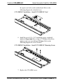
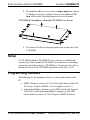
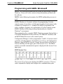
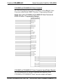
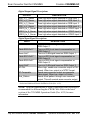
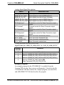
Crestron C2N-MMS-SC Scan Converter Card for C2N-MMS Operations & Installation Guide This document was prepared and written by the Technical Documentation department at: Crestron Electronics, Inc. 15 Volvo Drive Rockleigh, NJ 07647 1-888-CRESTRON All brand names, product names and trademarks are the property of their respective owners. ©2003 Crestron Electronics, Inc. Crestron C2N-MMS-SC Scan Converter Card for C2N-MMS Contents Scan Converter Card for C2N-MMS: C2N-MMS-SC 1 Introduction Features and Functions Specifications Physical Description Industry Compliance Installation and Hookup Setup Programming Software Programming with SIMPL Windows Programming with VisionTools™ Pro-e Problem Solving Troubleshooting Further Inquiries Future Updates Return and Warranty Policies Merchandise Returns / Repair Service CRESTRON Limited Warranty 1 1 2 4 5 5 8 8 9 16 16 16 17 17 18 18 18 Operations & Installation Guide - DOC. 6138 Contents • i Crestron C2N-MMS-SC Scan Converter Card for C2N-MMS Scan Converter Card for C2N-MMS: C2N-MMS-SC Introduction Features and Functions The C2N-MMS-SC scan converter card is designed for Crestron’s C2NMMS professional multimedia switch. The card contains a dedicated scan conversion chip that converts any of the C2N-MMS’ RGB input channels to either PAL or NTSC video signals for routing to either of the C2N-MMS’ Y/C (S-Video)/composite video outputs. The scan converter supports a variety of standard and non-standard resolutions at various refresh rates. Functional Summary • Converts RGB signals to Y/C (S-Video) or composite video signals in PAL or NTSC formats for routing to either or both of the video outputs of the C2N-MMS • Supports RGBHV VESA standard and non-standard resolutions (refer to “Specifications” for detailed information) • Easily installs into C2N-MMS multimedia switch with included hardware • Color and position adjustment control for scan converter signal • Built-in test pattern generator for display setup The following diagram illustrates the functional capabilities of the C2NMMS with the C2N-MMS-SC installed. Operations & Installation Guide - DOC. 6138 Scan Converter Card for C2N-MMS: C2N-MMS-SC • 1 Scan Converter Card for C2N-MMS Crestron C2N-MMS-SC Functional Diagram Video 1 IN Video 1 OUT 4 X 2 MUX Video 2 IN 100MHz Video 2 OUT OUT Video 3 IN SCAN CONVERTER PLUG-IN RGB HV1 IN RGB HV 1 OUT IN RGB HV 2 IN 4 X 3 MUX Cable Comp. RGB HV 3 IN RGB HV 2 OUT 400MHz RGB HV 3 IN Cable Comp. NOTE: All video input and output signals are through Y/C (S-video) or composite connections. Refer to the latest revision of the C2N-MMS Operations Guide (Doc. 6132) for more information. Specifications The following table provides a summary of specifications for the C2N-MMS-SC. Specifications of the C2N-MMS-SC SPECIFICATION Power Requirements Default NET ID DETAILS 6 Watts (0.25 Amp @ 24 VDC) 11 (continued on next page) 2 • Scan Converter Card for C2N-MMS: C2N-MMS-SC Operations & Installation Guide - DOC. 6138 Crestron C2N-MMS-SC Scan Converter Card for C2N-MMS C2N-MMS-SC Specifications (continued) SPECIFICATION DETAILS Video Output Types Video Formats C2N-MMS Firmware Control System Update Files1,2 2-Series Control System MP2/MP2E CNX-DVP4 Supported RGBHV Input Resolutions RGB Source Switch Time Operating Temperature and Humidity Dimensions and Weight NTSC or PAL, user selectable Composite or S-Video Version 2.06 or later Version C2-V3015.CUZ or later Version MP2-V3016.CUZ or later Version DVP4-3017.CUZ or later VESA Standard: 640 x 400 thru 1280 x 1024—All refresh rates 1600 x 1200 @ 60, 65, 70, 75 Hz 1792 x 1344 @ 60 Hz 1856 x 1392 @ 60 Hz 1920 x 1440 @ 60 Hz Non Standard: Min: 640 x 400 Max 2048 x 1536 (HSYNC 24 to 100 kHz and VSYNC 50 to 130 Hz) 4 seconds 41º to 104º F (5º to 40º C), 10 to 90% Relative Humidity (noncondensing) Height: 0.56 in (1.43 cm) Width: 4.00 in (10.16 cm) Depth: 2.50 in (6.35 cm) Weight: 1.4 oz (0.04 kg) 1. The latest versions can be obtained from the Downloads | Software Updates section of the Crestron website (www.crestron.com). Refer to NOTE after last footnote. 2. Crestron 2-Series control systems include the AV2, CP2, CP2E, MP2, MP2E, PAC2, PRO2, and RACK2. Operations & Installation Guide - DOC. 6138 Scan Converter Card for C2N-MMS: C2N-MMS-SC • 3 Scan Converter Card for C2N-MMS Crestron C2N-MMS-SC NOTE: Crestron software and any files on the website are for Authorized Crestron dealers and Crestron Authorized Independent Programmers (CAIP) only. New users may be required to register to obtain access to certain areas of the site (including the FTP site). Physical Description The C2N-MMS-SC is a printed circuit board (PCB) that is designed for installation into a dedicated expansion slot on the C2N-MMS motherboard. The card contains a 30-pin connector that attaches directly to the motherboard and is secured with two mounting screws (supplied). Refer to the following diagrams for physical dimensions. C2N-MMS-SC Top & Side View 4.00 in (10.16 cm) 2.50 in (6.35 cm) 0.06 in (0.16 cm) CONNECTOR 0.56 in (1.43 cm) NOTE: The diagrams above are for illustration purposes only and do not show components located on the circuit board. 4 • Scan Converter Card for C2N-MMS: C2N-MMS-SC Operations & Installation Guide - DOC. 6138 Crestron C2N-MMS-SC Scan Converter Card for C2N-MMS Industry Compliance As of the date of manufacture, the card has been tested and found to comply with specifications for CE marking and standards per EMC and Radiocommunications Compliance Labelling (N11785). NOTE: This device complies with part 15 of the FCC rules. Operation is subject to the following two conditions: (1) this device may not cause harmful interference, and (2) this device must accept any interference received, including interference that may cause undesired operation. Installation and Hookup The C2N-MMS-SC scan converter card is designed for installation into a dedicated expansion slot on the C2N-MMS multimedia switch. The only tools required for installation are a #2 Phillips screwdriver and a grounding strap (or grounded workstation). CAUTION: The C2N-MMS-SC and the C2N-MMS contain electrostatic discharge (ESD) sensitive devices. Perform the following procedure while wearing a grounding strap that is properly grounded and on a grounded workstation to avoid damaging the C2N-MMS-SC card and/or the C2N-MMS. CAUTION: To prevent stripping of screw heads, threads, or mounting holes, DO NOT overtighten screws. Tighten only to the specification listed in the individual step(s). 1. To prevent errors when re-connecting, label and disconnect all cables (if) attached to the C2N-MMS’ rear ports. 2. Using a #2 Phillips screwdriver, loosen and remove the 16 screws that secure the C2N-MMS cover. Refer to the following diagram for screw locations. Operations & Installation Guide - DOC. 6138 Scan Converter Card for C2N-MMS: C2N-MMS-SC • 5 Scan Converter Card for C2N-MMS Crestron C2N-MMS-SC C2N-MMS-SC Installation – Remove C2N-MMS Cover Screws 3. Remove the C2N-MMS cover by raising it upwards. 4. Using a #2 Phillips screwdriver, loosen and remove the two screws adjacent to the C2N-MMS motherboard connector. Refer to the following diagram for screw locations. C2N-MMS-SC Installation – Remove Motherboard Screws NOTE: These two screws must be removed prior to installing the C2N-MMS-SC 5. Align the pins on the connector of the C2N-MMS-SC with the C2N-MMS motherboard connector. DO NOT force pins into connector. Press the C2N-MMS-SC until the pins are fully seated. Make sure that the mounting posts of the card align with 6 • Scan Converter Card for C2N-MMS: C2N-MMS-SC Operations & Installation Guide - DOC. 6138 Crestron C2N-MMS-SC Scan Converter Card for C2N-MMS the open screw holes on the motherboard. Refer to the following diagram for a detailed view. C2N-MMS-SC Installation – Install C2N-MMS-SC Card 6. Install the two #6-32 x 3/4"L mounting screws (supplied), tighten to finger-tight then, using a # 2 Phillips screwdriver, tighten each screw an additional 1/8-turn. Refer to the following diagram for screw locations. C2N-MMS-SC Installation – Install C2N-MMS-SC Mounting Screws 7. Replace the C2N-MMS cover. Operations & Installation Guide - DOC. 6138 Scan Converter Card for C2N-MMS: C2N-MMS-SC • 7 Scan Converter Card for C2N-MMS Crestron C2N-MMS-SC 8. Re-install the 16 base cover screws to finger-tight then, using a #2 Phillips screwdriver, tighten each screw an additional 1/8turn. Refer to the following diagram for screw locations. C2N-MMS-SC Installation – Reinstall C2N-MMS Cover Screws 9. Re-connect all cables to the appropriate ports on the rear of the C2N-MMS. Setup A C2N-MMS with the C2N-MMS-SC scan converter is installed and connected just like a standard C2N-MMS. For instructions on installing, connecting, and addressing the C2N-MMS in a Cresnet network, refer to the latest revision of the C2N-MMS Operations Guide (Doc. 6132). Programming Software The following are the minimum software version requirements for the PC: • SIMPL Windows version 2.03.18 or later with Library Update file 202 or later. Requires SIMPL+ Cross Compiler version 1.1. • Application Builder (optional) version TBD (check with Crestron in 1Q 2003) with Application Builder Templates version TBD (check with Crestron in 1Q 2003). Requires SIMPL Windows. 8 • Scan Converter Card for C2N-MMS: C2N-MMS-SC Operations & Installation Guide - DOC. 6138 Crestron C2N-MMS-SC Scan Converter Card for C2N-MMS Programming with SIMPL Windows NOTE: The following assumes that the reader has knowledge of SIMPL Windows. If not, refer to the extensive help information provided with the software. NOTE: In the following description, the MP2E multimedia processor is used. SIMPL Windows is Crestron's software for programming Crestron control systems. It provides a well-designed graphical environment with a number of workspaces (i.e., windows) in which a programmer can select, configure, program, test, and monitor a Crestron control system. SIMPL Windows offers drag and drop functionality in a familiar Windows® environment. This section describes a sample SIMPL Windows program that includes a C2N-MMS Multimedia Switch (with the C2N-MMS-SC installed) with an MP2E Media Processor as the control system. Configuration Manager is where programmers “build” a Crestron control system by selecting hardware from the Device Library. In Configuration Manager, drag the MP2E from the Control Systems folder of the Device Library and drop it in the upper pane of the System Views. The MP2E with its associated communication ports is displayed in the System Views upper pane. MP2E System View The System Views lower pane displays the MP2E system tree. This tree can be expanded to display and configure the communications ports. Operations & Installation Guide - DOC. 6138 Scan Converter Card for C2N-MMS: C2N-MMS-SC • 9 Scan Converter Card for C2N-MMS Crestron C2N-MMS-SC Expanded MP2E System Tree C2Net-Device Slot in Configuration Manager To incorporate the C2N-MMS (with C2N-MMS-SC) into the system, drag the C2N-MMS w/C2N-MMS-SC Scan Converter from the Cresnet Control Modules | Cresnet Video Modules folder of the Device Library and drop it in the System Views. The MP2E system tree displays the device in slot 1 with a default NET ID of 11 as shown in the following illustration. NOTE: The first C2N-MMS in a system is preset with a NET ID of 11, when its symbol is dragged into the upper pane of System Views. Additional C2N-MMS devices (with or without the C2N-MMS-SC) are assigned different NET ID numbers as they are added. C2Net Device, Slot 1 10 • Scan Converter Card for C2N-MMS: C2N-MMS-SC Operations & Installation Guide - DOC. 6138 Crestron C2N-MMS-SC Scan Converter Card for C2N-MMS Setting the Net ID in Device Settings Double-click the C2N-MMS w/C2N-MMS-SC icon to open the “Device Settings” window. This window displays the C2N-MMS device information. If necessary, select the Net ID tab to change the Net ID, as shown in the following figure. “Device Settings” Window for the C2N-MMS w/C2N-MMS-SC NOTE: SIMPL Windows automatically changes NET ID values of a device added to a program if a duplicate device or a device with the same default NET ID already exists in the program. Always ensure that the hardware and software settings of the NET ID match. For NET ID hardware settings details, refer to the latest revision C2N-MMS Operations Guide (Doc. 6132). C2N-MMS Symbol in Programming Manager Programming Manager is where programmers “program” a Creston control system by assigning signals to symbols. Analog Initialize The inputs to the C2N-MMS w/C2N-MMS-SC symbol require the analog equivalent (0 through 4 for video and 0 through 4 for RGB where “0” is off) so that the video or RGB output can be switched to the specified input or turned off. Refer to the latest revision of the C2N-MMS Operations Guide (Doc. 6132) for creating the Analog Initialize modules for the RGB Output channels. Operations & Installation Guide - DOC. 6138 Scan Converter Card for C2N-MMS: C2N-MMS-SC • 11 Scan Converter Card for C2N-MMS Crestron C2N-MMS-SC Analog Initialize (For Scan Converter Output) From Touchpanel “PRESS” Inputs Analog Initialize (For Video Output 1) NOTE: A similar Analog Initialize symbol can be created for the input channel of Video Output 2 12 • Scan Converter Card for C2N-MMS: C2N-MMS-SC Operations & Installation Guide - DOC. 6138 Crestron C2N-MMS-SC Scan Converter Card for C2N-MMS C2N-MMS w/C2N-MMS-SC Scan Converter The following diagram shows the C2N-MMS w/C2N-MMS-SC Scan Converter symbol in the SIMPL Windows’ Programming Manager. Detail View of the C2N-MMS w/C2N-MMS-SC Scan Converter in SIMPL Windows’ Programming Manager C2N-MMS w/C2N-MMS-SC Scan Converter Input/Output Signals The following tables list and give functional descriptions for the C2N-MMS w/C2N-MMS-SC Scan Converter outputs and inputs. Operations & Installation Guide - DOC. 6138 Scan Converter Card for C2N-MMS: C2N-MMS-SC • 13 Scan Converter Card for C2N-MMS Crestron C2N-MMS-SC Digital Output Signal Descriptions OUTPUT DESCRIPTION RGB_In_1_Sense RGB_In_2_Sense RGB_In_3_Sense RGB_In_4_Sense VIDEO_In_1_Sense VIDEO_In_2_Sense VIDEO_In_3_Sense Goes high when signal detected on RGB Input 1. Goes high when signal detected on RGB Input 2. Goes high when signal detected on RGB Input 3. Goes high when signal detected on RGB Input 4. Goes high when signal detected on VIDEO Input 1. Goes high when signal detected on VIDEO Input 2. Goes high when signal detected on VIDEO Input 3. Digital Input Signal Descriptions INPUT Cable-EQ1-Out1* Cable-EQ2-Out1* Boost-Out1* Cable-EQ1-Out2* Cable-EQ2-Out2* Boost-Out2* SC-PAL SC-Composite Test_Pattern DESCRIPTION Turns on EQ1 level signal compensation on RGB Output 1. Turns on EQ2 level signal compensation on RGB Output 1. Turns on 3 dB signal boost on RGB Output 1. Turns on EQ1 level signal compensation on RGB Output 2. Turns on EQ2 level signal compensation on RGB Output 2. Turns on 3 dB signal boost on RGB Output 2. When high, sends scan converter output in PAL format. When low, output is in NTSC format. Sends scan converter output as composite video signal. When low, output is S-video. Sends a test pattern through scan converter output. This will override scan converter output. * Information on Cable-EQ & Boost signals can be found in the latest revision of the C2N-MMS Professional Multimedia Switch Installation Guide (Doc. 6132). NOTE: Different combinations of signal compensation and boosting are recommended for different lengths of RGB Cable. Refer to the latest revision of the C2N-MMS Operations Guide (Doc. 6132) for more information. 14 • Scan Converter Card for C2N-MMS: C2N-MMS-SC Operations & Installation Guide - DOC. 6138 Crestron C2N-MMS-SC Scan Converter Card for C2N-MMS Analog Input Signal Descriptions INPUT RGB_IN_For_Out1 RGB_IN_For_Out2 RGB_IN_For_SC VIDEO_IN_For_Out1 VIDEO_IN_For_Out2 SC-Brightness* SC-Contrast* SC-Saturation* SC-Sharpness* SC-H_Position* SC-H_SIZE* SC-V_POSITION* SC-V_SIZE* DESCRIPTION Input signal to route to RGB Output 1. Input signal to route to RGB Output 2. Input signal to route to Scan Converter. Input signal to route to VIDEO Output 1. Input signal to route to VIDEO Output 2. Brightness control for Scan Converter output signal. Contrast control for Scan Converter output signal. Saturation control for Scan Converter output signal. Sharpness control for Scan Converter output signal. Scan Converter horizontal position. Scan Converter horizontal size. Scan Converter vertical position. Scan Converter vertical size. * Analog input signal values range from 0 to 100%. Signal Values for “RGB_IN_FOR_OUTx” & “VID_IN_FOR_OUTx” SIGNAL VALUE 0 1 2 3 4 SOURCE No input source selected. No output. Source 1 (RGB_IN_FOR_OUTx & VID_IN_FOR_OUTx). Source 2 (RGB_IN_FOR_OUTx & VID_IN_FOR_OUTx). Source 3 (RGB_IN_FOR_OUTx & VID_IN_FOR_OUTx). Source 4 (RGB_IN_FOR_OUTx) OR Scan Converter (VID_IN_FOR_OUTx). Example Program An example program for the C2N-MMS-SC is available from the Crestron FTP site (ftp://ftp.crestron.com/Examples/). Search for the file C2N-MMS-SC.ZIP that contains the example program, associated files and a README.TXT file that describes the program. Operations & Installation Guide - DOC. 6138 Scan Converter Card for C2N-MMS: C2N-MMS-SC • 15 Scan Converter Card for C2N-MMS Crestron C2N-MMS-SC Programming with VisionTools™ Pro-e In addition to the touchpanel screens created in VT Pro-e for switching of source signals to desired outputs and selection of frequency compensation/signal boost, buttons should be created for selecting NTSC/PAL output format, selection of composite/S-video signal type, and activating the test pattern. There are no special programming requirements to use the functions of the C2N-MMS-SC in a room-control system. Problem Solving Troubleshooting The table below provides corrective action for possible trouble situations. If further assistance is required, please contact a Crestron customer service representative. C2N-MMS-SC Troubleshooting TROUBLE POSSIBLE CAUSE(S) Incorrect colors. Incorrect scan converter settings. Poor image quality or no image from Scan Converter. Cables improperly connected. C2N-MMS-SC installed incorrectly. CORRECTIVE ACTION Scan converter saturation, contrast and brightness should be set at 50%, 65% and 45% respectively for better display. Calibrate the scan converter using the test pattern. Verify that all cables are secure and that the source is operating. Reinstall C2N-MMS-SC. (continued on next page) 16 • Scan Converter Card for C2N-MMS: C2N-MMS-SC Operations & Installation Guide - DOC. 6138 Crestron C2N-MMS-SC Scan Converter Card for C2N-MMS C2N-MMS-SC Troubleshooting (continued) TROUBLE Image flicker. Blurry Image. POSSIBLE CAUSE(S) Incorrect setting. Source refresh rate is too high or too low. Resolution set too high. CORRECTIVE ACTION Adjust sharpness. Adjust refresh rate of source signal. Lower resolution setting of source signal. Further Inquiries If after reviewing this Operations & Installations Guide, you cannot locate specific information or have questions, please take advantage of Crestron's award winning customer service team by calling: • In the US and Canada, call Crestron’s corporate headquarters at 1-888-CRESTRON [1-888-273-7876]. • In Europe, call Crestron International at +32-15-50-99-50. • In Asia, call Crestron Asia at +852-2341-2016. • In Latin America, call Crestron Latin America at +5255-5093-2160. • In Australia and New Zealand, call Crestron Pacific at +613-9480-2999. Future Updates As Crestron improves functions, adds new features, and extends the capabilities of the C2N-MMS-SC, additional information may be made available as manual updates. These updates are solely electronic and serve as intermediary supplements prior to the release of a complete technical documentation revision. Check the Crestron website (www.crestron.com) periodically for manual update availability and its subjective value. Updates are available from the Download | Product Manuals section and are identified as an “Addendum” in the Download column. Operations & Installation Guide - DOC. 6138 Scan Converter Card for C2N-MMS: C2N-MMS-SC • 17 Scan Converter Card for C2N-MMS Crestron C2N-MMS-SC Return and Warranty Policies Merchandise Returns / Repair Service 1. No merchandise may be returned for credit, exchange, or service without prior authorization from CRESTRON. To obtain warranty service for CRESTRON products, contact the factory and request an RMA (Return Merchandise Authorization) number. Enclose a note specifying the nature of the problem, name and phone number of contact person, RMA number, and return address. 2. Products may be returned for credit, exchange, or service with a CRESTRON Return Merchandise Authorization (RMA) number. Authorized returns must be shipped freight prepaid to CRESTRON, Cresskill, N.J., or its authorized subsidiaries, with RMA number clearly marked on the outside of all cartons. Shipments arriving freight collect or without an RMA number shall be subject to refusal. CRESTRON reserves the right in its sole and absolute discretion to charge a 15% restocking fee, plus shipping costs, on any products returned with an RMA. 3. Return freight charges following repair of items under warranty shall be paid by CRESTRON, shipping by standard ground carrier. In the event repairs are found to be non-warranty, return freight costs shall be paid by the purchaser. CRESTRON Limited Warranty CRESTRON ELECTRONICS, Inc. warrants its products to be free from manufacturing defects in materials and workmanship under normal use for a period of three (3) years from the date of purchase from CRESTRON, with the following exceptions: disk drives and any other moving or rotating mechanical parts, pan/tilt heads and power supplies are covered for a period of one (1) year; touchscreen display and overlay components are covered for 90 days; batteries and incandescent lamps are not covered. This warranty extends to products purchased directly from CRESTRON or an authorized CRESTRON dealer. Purchasers should inquire of the dealer regarding the nature and extent of the dealer's warranty, if any. CRESTRON shall not be liable to honor the terms of this warranty if the product has been used in any application other than that for which it was intended, or if it has been subjected to misuse, accidental damage, modification, or improper installation procedures. Furthermore, this warranty does not cover any product that has had the serial number altered, defaced, or removed. This warranty shall be the sole and exclusive remedy to the original purchaser. In no event shall CRESTRON be liable for incidental or consequential damages of any kind (property or economic damages inclusive) arising from the sale or use of this equipment. CRESTRON is not liable for any claim made by a third party or made by the purchaser for a third party. CRESTRON shall, at its option, repair or replace any product found defective, without charge for parts or labor. Repaired or replaced equipment and parts supplied under this warranty shall be covered only by the unexpired portion of the warranty. Except as expressly set forth in this warranty, CRESTRON makes no other warranties, expressed or implied, nor authorizes any other party to offer any warranty, including any implied warranties of merchantability or fitness for a particular purpose. Any implied warranties that may be imposed by law are limited to the terms of this limited warranty. This warranty statement supercedes all previous warranties. Trademark Information All brand names, product names, and trademarks are the sole property of their respective owners. Windows is a registered trademark of Microsoft Corporation. Windows95/98/Me/XP and WindowsNT/2000 are trademarks of Microsoft Corporation. 18 • Scan Converter Card for C2N-MMS: C2N-MMS-SC Operations & Installation Guide - DOC. 6138 Crestron C2N-MMS-SC Scan Converter Card for C2N-MMS This page intentionally left blank. Operations & Installation Guide - DOC. 6138 Scan Converter Card for C2N-MMS: C2N-MMS-SC • 19 Crestron Electronics, Inc. Operations & Installation Guide - DOC. 6138 15 Volvo Drive Rockleigh, NJ 07647 02.03 Tel: 888.CRESTRON Fax: 201.767.7576 Specifications subject to www.crestron.com change without notice.