1
®
®
Avid Interplay Engine
Failover Guide for AS3000 Servers
Revision 4 Image
Legal Notices
Product specifications are subject to change without notice and do not represent a commitment on the part of Avid Technology, Inc.
This product is subject to the terms and conditions of a software license agreement provided with the software. The product may
only be used in accordance with the license agreement.
This product may be protected by one or more U.S. and non-U.S patents. Details are available at www.avid.com/patents.
This document is protected under copyright law. An authorized licensee of Interplay may reproduce this publication for the licensee’s
own use in learning how to use the software. This document may not be reproduced or distributed, in whole or in part, for
commercial purposes, such as selling copies of this document or providing support or educational services to others. This document
is supplied as a guide for [product name]. Reasonable care has been taken in preparing the information it contains. However, this
document may contain omissions, technical inaccuracies, or typographical errors. Avid Technology, Inc. does not accept
responsibility of any kind for customers’ losses due to the use of this document. Product specifications are subject to change without
notice.
Copyright © 2013 Avid Technology, Inc. and its licensors. All rights reserved.
The following disclaimer is required by Sam Leffler and Silicon Graphics, Inc. for the use of their TIFF library:
Copyright © 1988–1997 Sam Leffler
Copyright © 1991–1997 Silicon Graphics, Inc.
Permission to use, copy, modify, distribute, and sell this software [i.e., the TIFF library] and its documentation for any purpose is
hereby granted without fee, provided that (i) the above copyright notices and this permission notice appear in all copies of the
software and related documentation, and (ii) the names of Sam Leffler and Silicon Graphics may not be used in any advertising or
publicity relating to the software without the specific, prior written permission of Sam Leffler and Silicon Graphics.
THE SOFTWARE IS PROVIDED “AS-IS” AND WITHOUT WARRANTY OF ANY KIND, EXPRESS, IMPLIED OR OTHERWISE,
INCLUDING WITHOUT LIMITATION, ANY WARRANTY OF MERCHANTABILITY OR FITNESS FOR A PARTICULAR PURPOSE.
IN NO EVENT SHALL SAM LEFFLER OR SILICON GRAPHICS BE LIABLE FOR ANY SPECIAL, INCIDENTAL, INDIRECT OR
CONSEQUENTIAL DAMAGES OF ANY KIND, OR ANY DAMAGES WHATSOEVER RESULTING FROM LOSS OF USE, DATA OR
PROFITS, WHETHER OR NOT ADVISED OF THE POSSIBILITY OF DAMAGE, AND ON ANY THEORY OF LIABILITY, ARISING
OUT OF OR IN CONNECTION WITH THE USE OR PERFORMANCE OF THIS SOFTWARE.
The following disclaimer is required by the Independent JPEG Group:
This software is based in part on the work of the Independent JPEG Group.
This Software may contain components licensed under the following conditions:
Copyright (c) 1989 The Regents of the University of California. All rights reserved.
Redistribution and use in source and binary forms are permitted provided that the above copyright notice and this paragraph are
duplicated in all such forms and that any documentation, advertising materials, and other materials related to such distribution and
use acknowledge that the software was developed by the University of California, Berkeley. The name of the University may not be
used to endorse or promote products derived from this software without specific prior written permission. THIS SOFTWARE IS
PROVIDED ``AS IS'' AND WITHOUT ANY EXPRESS OR IMPLIED WARRANTIES, INCLUDING, WITHOUT LIMITATION, THE
IMPLIED WARRANTIES OF MERCHANTABILITY AND FITNESS FOR A PARTICULAR PURPOSE.
Copyright (C) 1989, 1991 by Jef Poskanzer.
Permission to use, copy, modify, and distribute this software and its documentation for any purpose and without fee is hereby
granted, provided that the above copyright notice appear in all copies and that both that copyright notice and this permission notice
appear in supporting documentation. This software is provided "as is" without express or implied warranty.
Copyright 1995, Trinity College Computing Center. Written by David Chappell.
Permission to use, copy, modify, and distribute this software and its documentation for any purpose and without fee is hereby
granted, provided that the above copyright notice appear in all copies and that both that copyright notice and this permission notice
appear in supporting documentation. This software is provided "as is" without express or implied warranty.
Copyright 1996 Daniel Dardailler.
Permission to use, copy, modify, distribute, and sell this software for any purpose is hereby granted without fee, provided that the
above copyright notice appear in all copies and that both that copyright notice and this permission notice appear in supporting
documentation, and that the name of Daniel Dardailler not be used in advertising or publicity pertaining to distribution of the software
without specific, written prior permission. Daniel Dardailler makes no representations about the suitability of this software for any
purpose. It is provided "as is" without express or implied warranty.
2
Modifications Copyright 1999 Matt Koss, under the same license as above.
Copyright (c) 1991 by AT&T.
Permission to use, copy, modify, and distribute this software for any purpose without fee is hereby granted, provided that this entire
notice is included in all copies of any software which is or includes a copy or modification of this software and in all copies of the
supporting documentation for such software.
THIS SOFTWARE IS BEING PROVIDED "AS IS", WITHOUT ANY EXPRESS OR IMPLIED WARRANTY. IN PARTICULAR,
NEITHER THE AUTHOR NOR AT&T MAKES ANY REPRESENTATION OR WARRANTY OF ANY KIND CONCERNING THE
MERCHANTABILITY OF THIS SOFTWARE OR ITS FITNESS FOR ANY PARTICULAR PURPOSE.
This product includes software developed by the University of California, Berkeley and its contributors.
The following disclaimer is required by Nexidia Inc.:
© 2010 Nexidia Inc. All rights reserved, worldwide. Nexidia and the Nexidia logo are trademarks of Nexidia Inc. All other
trademarks are the property of their respective owners. All Nexidia materials regardless of form, including without limitation,
software applications, documentation and any other information relating to Nexidia Inc., and its products and services are the
exclusive property of Nexidia Inc. or its licensors. The Nexidia products and services described in these materials may be covered
by Nexidia's United States patents: 7,231,351; 7,263,484; 7,313,521; 7,324,939; 7,406,415, 7,475,065; 7,487,086 and/or other
patents pending and may be manufactured under license from the Georgia Tech Research Corporation USA.
The following disclaimer is required by Paradigm Matrix:
Portions of this software licensed from Paradigm Matrix.
The following disclaimer is required by Ray Sauers Associates, Inc.:
“Install-It” is licensed from Ray Sauers Associates, Inc. End-User is prohibited from taking any action to derive a source code
equivalent of “Install-It,” including by reverse assembly or reverse compilation, Ray Sauers Associates, Inc. shall in no event be liable
for any damages resulting from reseller’s failure to perform reseller’s obligation; or any damages arising from use or operation of
reseller’s products or the software; or any other damages, including but not limited to, incidental, direct, indirect, special or
consequential Damages including lost profits, or damages resulting from loss of use or inability to use reseller’s products or the
software for any reason including copyright or patent infringement, or lost data, even if Ray Sauers Associates has been advised,
knew or should have known of the possibility of such damages.
The following disclaimer is required by Videomedia, Inc.:
“Videomedia, Inc. makes no warranties whatsoever, either express or implied, regarding this product, including warranties with
respect to its merchantability or its fitness for any particular purpose.”
“This software contains V-LAN ver. 3.0 Command Protocols which communicate with V-LAN ver. 3.0 products developed by
Videomedia, Inc. and V-LAN ver. 3.0 compatible products developed by third parties under license from Videomedia, Inc. Use of this
software will allow “frame accurate” editing control of applicable videotape recorder decks, videodisc recorders/players and the like.”
The following disclaimer is required by Altura Software, Inc. for the use of its Mac2Win software and Sample Source
Code:
©1993–1998 Altura Software, Inc.
The following disclaimer is required by 3Prong.com Inc.:
Certain waveform and vector monitoring capabilities are provided under a license from 3Prong.com Inc.
The following disclaimer is required by Interplay Entertainment Corp.:
The “Interplay” name is used with the permission of Interplay Entertainment Corp., which bears no responsibility for Avid products.
This product includes portions of the Alloy Look & Feel software from Incors GmbH.
This product includes software developed by the Apache Software Foundation (http://www.apache.org/).
© DevelopMentor
This product may include the JCifs library, for which the following notice applies:
JCifs © Copyright 2004, The JCIFS Project, is licensed under LGPL (http://jcifs.samba.org/). See the LGPL.txt file in the Third Party
Software directory on the installation CD.
Avid Interplay contains components licensed from LavanTech. These components may only be used as part of and in connection
with Avid Interplay.
3
Attn. Government User(s). Restricted Rights Legend
U.S. GOVERNMENT RESTRICTED RIGHTS. This Software and its documentation are “commercial computer software” or
“commercial computer software documentation.” In the event that such Software or documentation is acquired by or on behalf of a
unit or agency of the U.S. Government, all rights with respect to this Software and documentation are subject to the terms of the
License Agreement, pursuant to FAR §12.212(a) and/or DFARS §227.7202-1(a), as applicable.
Trademarks
003, 192 Digital I/O, 192 I/O, 96 I/O, 96i I/O, Adrenaline, AirSpeed, ALEX, Alienbrain, AME, AniMatte, Archive, Archive II, Assistant
Station, AudioPages, AudioStation, AutoLoop, AutoSync, Avid, Avid Active, Avid Advanced Response, Avid DNA, Avid DNxcel, Avid
DNxHD, Avid DS Assist Station, Avid Ignite, Avid Liquid, Avid Media Engine, Avid Media Processor, Avid MEDIArray, Avid Mojo, Avid
Remote Response, Avid Unity, Avid Unity ISIS, Avid VideoRAID, AvidRAID, AvidShare, AVIDstripe, AVX, Beat Detective, Beauty
Without The Bandwidth, Beyond Reality, BF Essentials, Bomb Factory, Bruno, C|24, CaptureManager, ChromaCurve,
ChromaWheel, Cineractive Engine, Cineractive Player, Cineractive Viewer, Color Conductor, Command|24, Command|8,
Control|24, Cosmonaut Voice, CountDown, d2, d3, DAE, D-Command, D-Control, Deko, DekoCast, D-Fi, D-fx, Digi 002, Digi 003,
DigiBase, Digidesign, Digidesign Audio Engine, Digidesign Development Partners, Digidesign Intelligent Noise Reduction,
Digidesign TDM Bus, DigiLink, DigiMeter, DigiPanner, DigiProNet, DigiRack, DigiSerial, DigiSnake, DigiSystem, Digital
Choreography, Digital Nonlinear Accelerator, DigiTest, DigiTranslator, DigiWear, DINR, DNxchange, Do More, DPP-1, D-Show, DSP
Manager, DS-StorageCalc, DV Toolkit, DVD Complete, D-Verb, Eleven, EM, Euphonix, EUCON, EveryPhase, Expander,
ExpertRender, Fader Pack, Fairchild, FastBreak, Fast Track, Film Cutter, FilmScribe, Flexevent, FluidMotion, Frame Chase, FXDeko,
HD Core, HD Process, HDpack, Home-to-Hollywood, HYBRID, HyperSPACE, HyperSPACE HDCAM, iKnowledge, Image
Independence, Impact, Improv, iNEWS, iNEWS Assign, iNEWS ControlAir, InGame, Instantwrite, Instinct, Intelligent Content
Management, Intelligent Digital Actor Technology, IntelliRender, Intelli-Sat, Intelli-sat Broadcasting Recording Manager, InterFX,
Interplay, inTONE, Intraframe, iS Expander, iS9, iS18, iS23, iS36, ISIS, IsoSync, LaunchPad, LeaderPlus, LFX, Lightning, Link &
Sync, ListSync, LKT-200, Lo-Fi, MachineControl, Magic Mask, Make Anything Hollywood, make manage move | media, Marquee,
MassivePack, Massive Pack Pro, Maxim, Mbox, Media Composer, MediaFlow, MediaLog, MediaMix, Media Reader, Media
Recorder, MEDIArray, MediaServer, MediaShare, MetaFuze, MetaSync, MIDI I/O, Mix Rack, Moviestar, MultiShell, NaturalMatch,
NewsCutter, NewsView, NewsVision, Nitris, NL3D, NLP, NSDOS, NSWIN, OMF, OMF Interchange, OMM, OnDVD, Open Media
Framework, Open Media Management, Painterly Effects, Palladium, Personal Q, PET, Podcast Factory, PowerSwap, PRE,
ProControl, ProEncode, Profiler, Pro Tools, Pro Tools|HD, Pro Tools LE, Pro Tools M-Powered, Pro Transfer, QuickPunch,
QuietDrive, Realtime Motion Synthesis, Recti-Fi, Reel Tape Delay, Reel Tape Flanger, Reel Tape Saturation, Reprise, Res Rocket
Surfer, Reso, RetroLoop, Reverb One, ReVibe, Revolution, rS9, rS18, RTAS, Salesview, Sci-Fi, Scorch, ScriptSync,
SecureProductionEnvironment, Serv|GT, Serv|LT, Shape-to-Shape, ShuttleCase, Sibelius, SimulPlay, SimulRecord, Slightly Rude
Compressor, Smack!, Soft SampleCell, Soft-Clip Limiter, SoundReplacer, SPACE, SPACEShift, SpectraGraph, SpectraMatte,
SteadyGlide, Streamfactory, Streamgenie, StreamRAID, SubCap, Sundance, Sundance Digital, SurroundScope, Symphony, SYNC
HD, SYNC I/O, Synchronic, SynchroScope, Syntax, TDM FlexCable, TechFlix, Tel-Ray, Thunder, TimeLiner, Titansync, Titan, TL
Aggro, TL AutoPan, TL Drum Rehab, TL Everyphase, TL Fauxlder, TL In Tune, TL MasterMeter, TL Metro, TL Space, TL Utilities,
tools for storytellers, Transit, TransJammer, Trillium Lane Labs, TruTouch, UnityRAID, Vari-Fi, Video the Web Way, VideoRAID,
VideoSPACE, VTEM, Work-N-Play, Xdeck, X-Form, Xmon and XPAND! are either registered trademarks or trademarks of Avid
Technology, Inc. in the United States and/or other countries.
Adobe and Photoshop are either registered trademarks or trademarks of Adobe Systems Incorporated in the United States and/or
other countries. Apple and Macintosh are trademarks of Apple Computer, Inc., registered in the U.S. and other countries. Windows
is either a registered trademark or trademark of Microsoft Corporation in the United States and/or other countries. All other
trademarks contained herein are the property of their respective owners.
Avid Interplay Engine Failover Guide for AS3000 Servers • 0130-07643-03 Rev C • February 2013 • Created 5/9/13
• This document is distributed by Avid in online (electronic) form only, and is not available for purchase in printed
form.
4
Contents
Using This Guide. . . . . . . . . . . . . . . . . . . . . . . . . . . . . . . . . . . . . . . . . . . . . . . . 9
Revision History . . . . . . . . . . . . . . . . . . . . . . . . . . . . . . . . . . . . . . . . . . . . . . . . . . . . . . . . 9
Symbols and Conventions . . . . . . . . . . . . . . . . . . . . . . . . . . . . . . . . . . . . . . . . . . . . . . . 10
If You Need Help. . . . . . . . . . . . . . . . . . . . . . . . . . . . . . . . . . . . . . . . . . . . . . . . . . . . . . . 10
Viewing Help and Documentation on the Interplay Portal. . . . . . . . . . . . . . . . . . . . . . . . 11
Avid Training Services . . . . . . . . . . . . . . . . . . . . . . . . . . . . . . . . . . . . . . . . . . . . . . . . . . 12
Chapter 1
Automatic Server Failover Introduction . . . . . . . . . . . . . . . . . . . . . . . . . . . . 13
Server Failover Overview . . . . . . . . . . . . . . . . . . . . . . . . . . . . . . . . . . . . . . . . . . . . . . . . 13
How Server Failover Works . . . . . . . . . . . . . . . . . . . . . . . . . . . . . . . . . . . . . . . . . . . . . . 14
Server Failover Configurations . . . . . . . . . . . . . . . . . . . . . . . . . . . . . . . . . . . . . . . . . . . . 16
Server Failover Requirements . . . . . . . . . . . . . . . . . . . . . . . . . . . . . . . . . . . . . . . . . . . . 19
Installing the Failover Hardware Components . . . . . . . . . . . . . . . . . . . . . . . . . . . . . . . . 20
AS3000 Slot Locations . . . . . . . . . . . . . . . . . . . . . . . . . . . . . . . . . . . . . . . . . . . . . . . 21
Failover Cluster Connections: Avid ISIS, Redundant-Switch Configuration. . . . . . . 21
Failover Cluster Connections, Dual-Connected Configuration . . . . . . . . . . . . . . . . 23
Clustering Technology and Terminology. . . . . . . . . . . . . . . . . . . . . . . . . . . . . . . . . . . . . 25
Chapter 2
Creating a Microsoft Failover Cluster . . . . . . . . . . . . . . . . . . . . . . . . . . . . . 26
Server Failover Installation Overview . . . . . . . . . . . . . . . . . . . . . . . . . . . . . . . . . . . . . . . 26
Before You Begin the Server Failover Installation . . . . . . . . . . . . . . . . . . . . . . . . . . . . . 27
Requirements for Domain User Accounts . . . . . . . . . . . . . . . . . . . . . . . . . . . . . . . . 27
List of IP Addresses and Network Names . . . . . . . . . . . . . . . . . . . . . . . . . . . . . . . . 29
Active Directory and DNS Requirements . . . . . . . . . . . . . . . . . . . . . . . . . . . . . . . . . 32
Preparing the Server for the Cluster Service . . . . . . . . . . . . . . . . . . . . . . . . . . . . . . . . . 33
Changing Default Settings for the ATTO Card on Each Node . . . . . . . . . . . . . . . . . 33
Changing Windows Server Settings on Each Node . . . . . . . . . . . . . . . . . . . . . . . . . 36
Renaming the Local Area Network Interface on Each Node . . . . . . . . . . . . . . . . . . 36
Configuring the Private Network Adapter on Each Node . . . . . . . . . . . . . . . . . . . . . 39
Configuring the Binding Order Networks on Each Node . . . . . . . . . . . . . . . . . . . . . 43
Configuring the Public Network Adapter on Each Node. . . . . . . . . . . . . . . . . . . . . . 44
Configuring the Cluster Shared-Storage RAID Disks on Each Node . . . . . . . . . . . . 45
Configuring the Cluster Service . . . . . . . . . . . . . . . . . . . . . . . . . . . . . . . . . . . . . . . . . . . 49
Joining Both Servers to the Active Directory Domain. . . . . . . . . . . . . . . . . . . . . . . . 49
Installing the Failover Clustering Feature. . . . . . . . . . . . . . . . . . . . . . . . . . . . . . . . . 49
Creating the Cluster Service . . . . . . . . . . . . . . . . . . . . . . . . . . . . . . . . . . . . . . . . . . 52
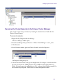
Renaming the Cluster Networks in the Failover Cluster Manager . . . . . . . . . . . . . . 58
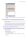
Renaming Cluster Disk 1 and Deleting the Remaining Cluster Disks . . . . . . . . . . . 60
Adding a Second IP Address to the Cluster . . . . . . . . . . . . . . . . . . . . . . . . . . . . . . . 62
Testing the Cluster Installation . . . . . . . . . . . . . . . . . . . . . . . . . . . . . . . . . . . . . . . . . 67
Chapter 3
Installing the Interplay Engine for a Failover Cluster . . . . . . . . . . . . . . . . . 70
Disabling Any Web Servers . . . . . . . . . . . . . . . . . . . . . . . . . . . . . . . . . . . . . . . . . . . . . . 70
Installing the Interplay Engine on the First Node . . . . . . . . . . . . . . . . . . . . . . . . . . . . . . 71
Preparation for Installing on the First Node . . . . . . . . . . . . . . . . . . . . . . . . . . . . . . . 71
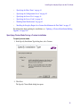
Bringing the Shared Database Drive Online . . . . . . . . . . . . . . . . . . . . . . . . . . . . . . 72
Starting the Installation and Accepting the License Agreement . . . . . . . . . . . . . . . . 74
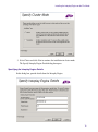
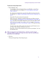
Installing the Interplay Engine Using Custom Mode. . . . . . . . . . . . . . . . . . . . . . . . . 74
Checking the Status of the Resource Group . . . . . . . . . . . . . . . . . . . . . . . . . . . . . . 89
Creating the Database Share Manually . . . . . . . . . . . . . . . . . . . . . . . . . . . . . . . . . . 91
Adding a Second IP Address (Dual-Connected Configuration) . . . . . . . . . . . . . . . . 92
Changing the Resource Name of the Avid Workgroup Server. . . . . . . . . . . . . . . . . 98
Installing the Interplay Engine on the Second Node . . . . . . . . . . . . . . . . . . . . . . . . . . . 100
Bringing the Interplay Engine Online. . . . . . . . . . . . . . . . . . . . . . . . . . . . . . . . . . . . . . . 101
After Installing the Interplay Engine . . . . . . . . . . . . . . . . . . . . . . . . . . . . . . . . . . . . . . . 102
Creating an Interplay Database . . . . . . . . . . . . . . . . . . . . . . . . . . . . . . . . . . . . . . . . . . 103
Testing the Complete Installation . . . . . . . . . . . . . . . . . . . . . . . . . . . . . . . . . . . . . . . . . 103
Installing a Permanent License . . . . . . . . . . . . . . . . . . . . . . . . . . . . . . . . . . . . . . . . . . . 104
Updating a Clustered Installation (Rolling Upgrade) . . . . . . . . . . . . . . . . . . . . . . . . . . . 105
Uninstalling the Interplay Engine on a Clustered System . . . . . . . . . . . . . . . . . . . . . . . 107
6
Chapter 4
Automatic Server Failover Tips and Rules . . . . . . . . . . . . . . . . . . . . . . . . . 110
Appendix A
Windows Server Settings Included in Latest Image . . . . . . . . . . . . . . . . . 112
Creating New GUIDs for the AS3000 Network Adapters . . . . . . . . . . . . . . . . . . . . . . . 112
Removing the Web Server IIS Role . . . . . . . . . . . . . . . . . . . . . . . . . . . . . . . . . . . . . . . 115
Removing the Failover Clustering Feature . . . . . . . . . . . . . . . . . . . . . . . . . . . . . . . . . . 115
Disabling IPv6 . . . . . . . . . . . . . . . . . . . . . . . . . . . . . . . . . . . . . . . . . . . . . . . . . . . . . . . . 118
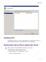
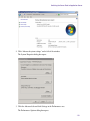
Switching the Server Role to Application Server. . . . . . . . . . . . . . . . . . . . . . . . . . . . . . 118
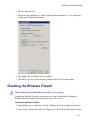
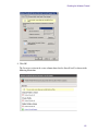
Disabling the Windows Firewall . . . . . . . . . . . . . . . . . . . . . . . . . . . . . . . . . . . . . . . . . . 120
Index . . . . . . . . . . . . . . . . . . . . . . . . . . . . . . . . . . . . . . . . . . . . . . . . . . . . . . . . 123
7
8
Using This Guide
Congratulations on the purchase of your Avid® Interplay™, a powerful system for managing
media in a shared storage environment.
This guide is intended for all Avid Interplay administrators who are responsible for installing,
configuring, and maintaining an Avid Interplay Engine with the Automatic Server Failover
module integrated. This guide is for Interplay Engine clusters that use Avid AS3000 servers.
n
The documentation describes the features and hardware of all models. Therefore, your system
might not contain certain features and hardware that are covered in the documentation.
Revision History
Date Revised
Changes Made
May 2013
Revisions to remove support for Infortrend A16F-R2431with the new ATTO FC-81EN
card, and to describe login to the ATTO Configuration Tool (“Changing Default Settings
for the ATTO Card on Each Node” on page 33.).
February 2013
Revisions to describe Rev. 4 image (including new appendix “Windows Server Settings
Included in Latest Image” on page 112).
November 2012
Moved information on preparing server from “Preparing the Server for the Cluster
Service” on page 33 to “Windows Server Settings Included in Latest Image” on
page 112.
January 10, 2012
Corrected step 1 in “Starting the Installation and Accepting the License Agreement” on
page 74 and added cross-reference in “Testing the Complete Installation” on page 103.
January 6, 2012
Revised “Testing the Cluster Installation” on page 67 for additional enhancements.
December 12, 2011 Revised “Testing the Cluster Installation” on page 67 to describe command line method.
November 7, 2011
Revisions include the following:
•
“Requirements for Domain User Accounts” on page 27. Expanded description and
use of cluster installation account.
•
“Testing the Cluster Installation” on page 67: Corrected to show both networks
online.
Symbols and Conventions
Symbols and Conventions
Avid documentation uses the following symbols and conventions:
Symbol or Convention Meaning or Action
n
A note provides important related information, reminders,
recommendations, and strong suggestions.
c
A caution means that a specific action you take could cause harm to
your computer or cause you to lose data.
w
>
A warning describes an action that could cause you physical harm.
Follow the guidelines in this document or on the unit itself when
handling electrical equipment.
This symbol indicates menu commands (and subcommands) in the
order you select them. For example, File > Import means to open the
File menu and then select the Import command.
This symbol indicates a single-step procedure. Multiple arrows in a list
indicate that you perform one of the actions listed.
(Windows), (Windows
only), (Macintosh), or
(Macintosh only)
This text indicates that the information applies only to the specified
operating system, either Windows or Macintosh OS X.
Bold font
Bold font is primarily used in task instructions to identify user interface
items and keyboard sequences.
Italic font
Italic font is used to emphasize certain words and to indicate variables.
Courier Bold font
Courier Bold font identifies text that you type.
Ctrl+key or mouse action
Press and hold the first key while you press the last key or perform the
mouse action. For example, Command+Option+C or Ctrl+drag.
If You Need Help
If you are having trouble using your Avid product:
1. Retry the action, carefully following the instructions given for that task in this guide. It is
especially important to check each step of your workflow.
2. Check the latest information that might have become available after the documentation was
published:
10
Viewing Help and Documentation on the Interplay Portal
-
If the latest information for your Avid product is provided as printed release notes, they
are shipped with your application and are also available online.
-
If the latest information for your Avid product is provided as a ReadMe file, it is
supplied on your Avid installation media as a PDF document (README_product.pdf)
and is also available online.
You should always check online for the most up-to-date release notes or ReadMe
because the online version is updated whenever new information becomes available. To
view these online versions, select ReadMe from the Help menu, or visit the Knowledge Base
at www.avid.com/support.
3. Check the documentation that came with your Avid application or your hardware for
maintenance or hardware-related issues.
4. Visit the online Knowledge Base at www.avid.com/support. Online services are available 24
hours per day, 7 days per week. Search this online Knowledge Base to find answers, to view
error messages, to access troubleshooting tips, to download updates, and to read or join
online message-board discussions.
Viewing Help and Documentation on the Interplay
Portal
You can quickly access the Interplay Help, PDF versions of the Interplay guides, and useful
external links by viewing the Interplay User Information Center on the Interplay Portal. The
Interplay Portal is a web site that runs on the Interplay Engine.
You can access the Interplay User Information Center through a browser from any system in the
Interplay environment. You can also access it through the Help menu in Interplay Access and the
Interplay Administrator.
The Interplay Help combines information from all Interplay guides in one Help system. It
includes a combined index and a full-featured search. From the Interplay Portal, you can run the
Help in a browser or download a compiled (.chm) version for use on other systems, such as a
laptop.
To open the Interplay User Information Center through a browser:
1. Type the following line in a web browser:
http://Interplay_Engine_name
For Interplay_Engine_name substitute the name of the computer running the Interplay
Engine software. For example, the following line opens the portal web page on a system
named docwg:
http://docwg
11
Avid Training Services
2. Click the “Avid Interplay Documentation” link to access the User Information Center web
page.
To open the Interplay User Information Center from Interplay Access or the Interplay
Administrator:
t
Select Help > Documentation Website on Server.
Avid Training Services
Avid makes lifelong learning, career advancement, and personal development easy and
convenient. Avid understands that the knowledge you need to differentiate yourself is always
changing, and Avid continually updates course content and offers new training delivery methods
that accommodate your pressured and competitive work environment.
For information on courses/schedules, training centers, certifications, courseware, and books,
please visit www.avid.com/support and follow the Training links, or call Avid Sales at
800-949-AVID (800-949-2843).
12
1 Automatic Server Failover Introduction
This chapter covers the following topics:
•
Server Failover Overview
•
How Server Failover Works
•
Installing the Failover Hardware Components
•
Clustering Technology and Terminology
Server Failover Overview
The automatic server failover mechanism in Avid Interplay allows client access to the Interplay
Engine in the event of failures or during maintenance, with minimal impact on the availability. A
failover server is activated in the event of application, operating system, or hardware failures.
The server can be configured to notify the administrator about such failures using email.
The Interplay implementation of server failover uses Microsoft® clustering technology. For
background information on clustering technology and links to Microsoft clustering information,
see “Clustering Technology and Terminology” on page 25.
c
Additional monitoring of the hardware and software components of a high-availability
solution is always required. Avid delivers Interplay preconfigured, but additional attention
on the customer side is required to prevent outage (for example, when a private network
fails, RAID disk fails, or a power supply loses power). In a mission critical environment,
monitoring tools and tasks are needed to be sure there are no silent outages. If another
(unmonitored) component fails, only an event is generated, and while this does not
interrupt availability, it might go unnoticed and lead to problems. Additional software
reporting such issues to the IT administration lowers downtime risk.
The failover cluster is a system made up of two server nodes and a shared-storage device
connected over Fibre Channel. These are to be deployed in the same location given the shared
access to the storage device. The cluster uses the concept of a “virtual server” to specify groups
of resources that failover together. This virtual server is referred to as a “cluster application” in
the failover cluster user interface.
How Server Failover Works
The following diagram illustrates the components of a cluster group, including sample IP
addresses. For a list of required IP addresses and node names, see “List of IP Addresses and
Network Names” on page 29.
Cluster Group
Intranet
Resource groups
Clustered
services
Failover Cluster
11.22.33.200
Node #1
Intranet: 11.22.33.44
Private: 10.10.10.10
Interplay Server
(cluster application)
11.22.33.201
Private Network
Node #2
Intranet: 11.22.33.45
Private: 10.10.10.11
FibreChannel
Disk resources
(shared disks)
n
Disk #1
Quorum
Disk #3
Database
If you are already using clusters, the Avid Interplay Engine will not interfere with your
current setup.
How Server Failover Works
Server failover works on two different levels:
•
Failover in case of hardware failure
•
Failover in case of network failure
Hardware Failover Process
When the Microsoft cluster service is running on both systems and the server is deployed in
cluster mode, the Interplay Engine and its accompanying services are exposed to users as a
virtual server (or cluster application). To clients, connecting to the clustered virtual Interplay
Engine appears to be the same process as connecting to a single, physical machine. The user or
client application does not know which node is actually hosting the virtual server.
14
How Server Failover Works
When the server is online, the resource monitor regularly checks its availability and
automatically restarts the server or initiates a failover to the other node if a failure is detected.
The exact behavior can be configured using the Failover Cluster Manager. Because clients
connect to the virtual network name and IP address, which are also taken over by the failover
node, the impact on the availability of the server is minimal.
Network Failover Process
Avid supports a configuration that uses connections to two public networks (VLAN 10 and
VLAN 20) on a single switch. The cluster monitors both networks. If one fails, the cluster
application stays on line and can still be reached over the other network. If the switch fails, both
networks monitored by the cluster will fail simultaneously and the cluster application will go
offline.
For a high degree of protection against network outages, Avid supports a configuration that uses
two network switches, each connected to a shared primary network (VLAN 30) and protected by
a failover protocol. If one network switch fails, the virtual server remains online through the
other VLAN 30 network and switch.
These configurations are described in the next section.
Changes for Windows Server 2008
This document describes a cluster configuration that uses the cluster application supplied with
Windows Server 2008 R2 Enterprise. The cluster creation process is simpler than that used for
Windows Server 2003, and eliminates the need to rely on a primary network. Requirements for
the Microsoft cluster installation account have changed (see “Requirements for Domain User
Accounts” on page 27). Requirements for DNS entries have also changed (see “Active Directory
and DNS Requirements” on page 32).
Installation of the Interplay Engine and Interplay Archive Engine now supports Windows Server
2008, but otherwise has not changed.
15
Server Failover Configurations
Server Failover Configurations
There are two supported configurations for integrating a failover cluster into an existing network:
•
A cluster in an Avid ISIS environment that is integrated into the intranet through two layer-3
switches (VLAN 30 in Zone 3). This “redundant-switch” configuration protects against both
hardware and network outages and thus provides a higher level of protection than the
dual-connected configuration.
•
A cluster in an Avid ISIS environment that is integrated into the intranet through two public
networks (VLAN 10 and VLAN 20 in Zone 1). This “dual-connected” configuration
protects against hardware outages and network outages. If one network fails, the cluster
application stays on line and can be reached over the other network.
Redundant-Switch Configuration
The following diagram illustrates the failover cluster architecture for an Avid ISIS environment
that uses two layer-3 switches. These switches are configured for failover protection through
either HSRP (Hot Standby Router Protocol) or VRRP (Virtual Router Redundancy Protocol).
The cluster nodes are connected to two subnets (VLAN 30), each on a different switch. If one of
the VLAN 30 networks fails, the virtual server remains online through the other VLAN 30
network and switch.
n
This guide does not describe how to configure redundant switches for an Avid ISIS media
network. Configuration information is included in the ISIS Qualified Switch Reference Guide,
which is available for download from the Avid Customer Support Knowledge Base at
www.avid.com\onlinesupport.
16
Server Failover Configurations
Two-Node Cluster in an Avid ISIS Environment (Redundant-Switch Configuration)
Avid network switch 2
running VRRP or HSRP
VLAN 30
Avid network switch 1
running VRRP or HSRP
VLAN 30
Interplay editing
clients
Interplay Engine cluster node 1
Private network
for heartbeat
Infortrend
Raid Array
Interplay Engine cluster node 2
LEGEND
1 GB Ethernet connection
Fibre Channel connection
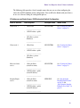
The following table describes what happens in the redundant-switch configuration as a result of
an outage:
Type of Outage
Result
Hardware (CPU, network adapter,
memory, cable, power supply) fails
The cluster detects the outage and triggers failover to the remaining node.
Network switch 1 (VLAN 30) fails
External switches running VRRP/HSRP detect the outage and make the
gateway available as needed.
The Interplay Engine is still accessible.
The Interplay Engine is still accessible.
Network switch 2 (VLAN 30) fails
External switches running VRRP/HSRP detect the outage and make the
gateway available as needed.
The Interplay Engine is still accessible.
17
Server Failover Configurations
Dual-Connected Configuration
The following diagram illustrates the failover cluster architecture for an Avid ISIS environment.
In this environment, each cluster node is “dual-connected” to the network switch: one network
interface is connected to the VLAN 10 subnet and the other is connected to the VLAN 20 subnet.
If one of the subnets fails, the virtual server remains online through the other subnet.
Two-Node Cluster in an Avid ISIS Environment (Dual-Connected Configuration)
Avid network switch 1
running VRRP or HSRP
VLAN 10
Interplay editing
clients
VLAN 20
Interplay Engine cluster node 1
Private network
for heartbeat
Infortrend
RAID array
Interplay Engine cluster node 2
LEGEND
1 GB Ethernet connection
Fibre Channel Connection
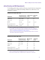
The following table describes what happens in the dual-connected configuration as a result of an
outage:
Type of Outage
Result
Hardware (CPU, network adapter,
memory, cable, power supply) fails
The cluster detects the outage and triggers failover to the remaining node.
Left ISIS VLAN (VLAN10) fails
The Interplay Engine is still accessible through the right network.
Right ISIS VLAN (VLAN 20) fails
The Interplay Engine is still accessible through the left network.
The Interplay Engine is still accessible.
18
Server Failover Requirements
Server Failover Requirements
You should make sure the server failover system meets the following requirements.
Hardware
The automatic server failover system was qualified with the following hardware:
c
•
Two Avid AS3000 servers functioning as nodes in a failover cluster. For installation
information, see the Avid AS3000 Setup Guide.
•
Two ATTO Celerity FC-81EN Fibre Channel host adapters (one for each server in the
cluster), installed in the top PCIe slot.
•
One Infortrend® S12F-R1440. For more information, see the Infortrend EonStor®DS
S12F-R1440 Installation and Hardware Reference Manual.
The Infortrend A16F-R2431 (Gen 2) is not supported for use with the FC-81EN host
adapter.
The servers in a cluster are connected using one or more cluster shared-storage buses and one or
more physically independent networks acting as a heartbeat.
Server Software
The automatic failover system was qualified on the following operating system:
•
Windows Server 2008 R2 Enterprise
A license for the Interplay Engine failover cluster is required. A license for a failover cluster
includes two hardware IDs. For installation information, see “Installing a Permanent License” on
page 104.
Space Requirements
The default disk configuration for the Infortrend shared RAID arrays are as follows:
Disk
Infortrend
S12F-R1440
Disk 1 Quorum disk
10 GB
Disk 2 (not used)
10 GB
Disk 3 Database disk
814 GB or larger
19
Installing the Failover Hardware Components
Antivirus Software
You can run antivirus software on a cluster, if the antivirus software is cluster-aware. For
information about cluster-aware versions of your antivirus software, contact the antivirus vendor.
If you are running antivirus software on a cluster, make sure you exclude these locations from the
virus scanning: Q:\ (Quorum disk), C:\Windows\Cluster, and S:\Workgroup_Databases
(database).
Functions You Need To Know
Before you set up a cluster in an Avid Interplay environment, you should be familiar with the
following functions:
•
Microsoft Windows Active Directory domains and domain users
•
Microsoft Windows clustering for Windows Server 2008 (see “Clustering Technology and
Terminology” on page 25)
•
Disk configuration (format, partition, naming)
•
Network configuration
For information about Avid Networks and Interplay Production, search for document
244197 “Network Requirements for ISIS and Interplay Production” on the Customer
Support Knowledge Base at www.avid.com/onlinesupport.
Installing the Failover Hardware Components
A failover cluster system includes the following components:
•
Two Interplay Engine nodes or two Interplay Archive nodes (two AS3000 servers)
•
One Infortrendcluster shared-storage RAID array (Infortrend S12F-R1440)
The following topics provide information about installing the failover hardware components for
the supported configurations:
•
“AS3000 Slot Locations” on page 21
•
“Failover Cluster Connections: Avid ISIS, Redundant-Switch Configuration” on page 21
•
“Failover Cluster Connections, Dual-Connected Configuration” on page 23
20
Installing the Failover Hardware Components
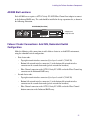
AS3000 Slot Locations
Each AS3000 server requires a ATTO Celerity FC-81EN Fibre Channel host adapter to connect
to the Infortrend RAID array. The card should be installed in the top expansion slot, as shown in
the following illustration.
Avid AS3000 (Rear View)
1
2
3
4
Adapter card
in top PCIe slot
Failover Cluster Connections: Avid ISIS, Redundant-Switch
Configuration
Make the following cable connections to add a failover cluster to an Avid ISIS environment,
using the redundant-switch configuration:
•
•
First cluster node:
-
Top-right network interface connector (2) to layer-3 switch 1 (VLAN 30)
-
Bottom-left network interface connector (3) to the bottom-left network interface
connector on the second cluster node (private network for heartbeat)
-
Fibre Channel connector on the ATTO Celerity FC-81EN card to the Fibre Channel top
connector on the Infortrend RAID array.
Second cluster node:
-
Top-right network interface connector (2) to layer-3 switch 2 (VLAN 30)
-
Bottom-left network interface connector (3) to the bottom-left network interface
connector on the second cluster node (private network for heartbeat)
-
Fibre Channel connector on the ATTO Celerity FC-81EN card to the Fibre Channel
bottom connector on the Infortrend RAID array.
21
Installing the Failover Hardware Components
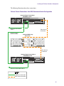
The following illustration shows these connections.
Failover Cluster Connections: Avid ISIS, Redundant-Switch Configuration
Interplay Engine Cluster Node 1
AS3000 Back Panel
1
2
3
4
Ethernet to Avid network
switch 1
Ethernet to node 2
(Private network)
Fibre Channel
to Infortrend
Infortrend RAID Array
Back Panel
Fibre Channel
to Infortrend
Interplay Engine Cluster Node 2
AS3000 Back Panel
1
2
3
4
Ethernet to Avid network switch 2
LEGEND
1 GB Ethernet connection
Fibre Channel connection
22
Installing the Failover Hardware Components
Failover Cluster Connections, Dual-Connected Configuration
Make the following cable connections to add a failover cluster to an Avid ISIS environment as a
dual-connected configuration:
•
•
First cluster node (AS3000):
-
Top-right network interface connector (2) to the ISIS left subnet (VLAN 10 public
network)
-
Bottom-right network interface connector (4) to the ISIS right subnet (VLAN 20 public
network)
-
Bottom-left network interface connector (3) to the bottom-left network interface
connector on the second cluster node (private network for heartbeat)
-
Fibre Channel connector on the ATTO Celerity FC-81EN card to the Fibre Channel top
connector on the Infortrend RAID array.
Second cluster node (AS3000):
-
Top-right network interface connector (2) to the ISIS left subnet (VLAN 10 public
network)
-
Bottom-right network interface connector (4) to the ISIS right subnet (VLAN 20 public
network)
-
Bottom-left network interface connector (3) to the bottom-left network interface
connector on the first cluster node (private network for heartbeat)
-
Fibre Channel connector on the ATTO Celerity FC-81EN card to the Fibre Channel
bottom connector on the Infortrend RAID array.
23
Installing the Failover Hardware Components
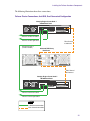
The following illustration shows these connections.
Failover Cluster Connections, Avid ISIS, Dual-Connected Configuration
Interplay Engine Cluster Node 1
AS3000 Back Panel
1
2
3
4
Ethernet to ISIS left subnet
Ethernet to ISIS right subnet
Ethernet to node 2
(Private network)
Fibre Channel
to Infortrend
Infortrend RAID Array
Back Panel
Fibre Channel
to Infortrend
Interplay Engine Cluster Node 2
AS3000 Back Panel
1
2
3
4
Ethernet to ISIS left subnet
Ethernet to ISIS right subnet
LEGEND
1 GB Ethernet connection
Fibre Channel connection
24
Clustering Technology and Terminology
Clustering Technology and Terminology
Clustering is not always straightforward, so it is important that you get familiar with the
technology and terminology of failover clusters before you start. A good source of information is
the Windows Server 2008 R2 Failover Clustering resource site:
www.microsoft.com/windowsserver2008/en/us/failover-clustering-technical.aspx
The following link describes the role of the quorum in a cluster:
http://technet.microsoft.com/en-us/library/cc770620(WS.10).aspx
Here is a brief summary of the major concepts and terms:
•
Nodes: Individual computers in a cluster configuration.
•
Cluster service: A Windows service that provides the cluster functionality. When this service
is stopped, the node appears offline to other cluster nodes.
•
Resource: Cluster components (hardware and software) that are managed by the cluster
service. Resources are physical hardware devices such as disk drives, and logical items such
as IP addresses and applications.
•
Online resource: A resource that is available and is providing its service.
•
Quorum: A special common cluster resource. This resource plays a critical role in cluster
operations.
•
Resource group: A collection of resources that are managed by the cluster service as a
single, logical unit and that are always brought online on the same node.
25
2
Creating a Microsoft Failover Cluster
This chapter describes the processes for creating a Microsoft failover cluster for automatic server
failover. It is crucial that you follow the instructions given in this chapter completely, otherwise
the automatic server failover will not work.
This chapter covers the following topics:
•
Server Failover Installation Overview
•
Before You Begin the Server Failover Installation
•
Preparing the Server for the Cluster Service
•
Configuring the Cluster Service
Instructions for installing the Interplay Engine are provided in “Installing the Interplay Engine
for a Failover Cluster” on page 70.
Server Failover Installation Overview
Installation and configuration of the automatic server failover consists of the following major
tasks:
n
•
Make sure that the network is correctly set up and that you have reserved IP host names and
IP addresses (see “Before You Begin the Server Failover Installation” on page 27).
•
Prepare the servers for the cluster service (see “Preparing the Server for the Cluster Service”
on page 33). This includes configuring the nodes for the network and formatting the drives.
•
Configure the cluster service (see “Configuring the Cluster Service” on page 49).
•
Install the Interplay Engine on both nodes (see “Installing the Interplay Engine for a Failover
Cluster” on page 70).
•
Test the complete installation (see “Testing the Complete Installation” on page 103).
Do not install any other software on the cluster machines except the Interplay engine. For
example, Media Indexer software needs to be installed on a different server. For complete
installation instructions, see the Avid Interplay Software Installation and Configuration Guide.
Before You Begin the Server Failover Installation
For more details about Microsoft clustering technology, see the Windows Server 2008 R2
Failover Clustering resource site:
www.microsoft.com/windowsserver2008/en/us/failover-clustering-technical.aspx
Before You Begin the Server Failover Installation
Before you begin the installation process, you need to do the following:
•
Make sure all cluster hardware connections are correct. See “Installing the Failover
Hardware Components” on page 20.
•
Make sure that the site has a network that is qualified to run Active Directory and DNS
services.
•
Make sure the network includes an Active Directory domain before you install or configure
the cluster.
•
Determine the subnet mask, the gateway, DNS, and WINS server addresses on the network.
•
Reserve static IP addresses for all network interfaces and host names. See “List of IP
Addresses and Network Names” on page 29.
•
Make sure the time settings for both nodes are in sync. If not, you must synchronize the
times or you will not be able to add both nodes to the cluster.
•
Make sure the Remote Registry service is started and is enabled for Automatic startup. Open
Server Management and select Configuration > Services > Remote Registry.
•
Create or select domain user accounts for creating and administering the cluster. See
“Requirements for Domain User Accounts” on page 27.
•
Create an Avid shared-storage user account with read and write privileges. This account is
not needed for the installation of the Interplay Engine, but is required for the operation of the
Interplay Engine (for example, media deletion from shared-storage). The user name and
password must exactly match the user name and password of the Server Execution User.
•
Be prepared to install and set up an Avid shared-storage client on both servers after the
failover cluster configuration and Interplay Engine installation is complete. See the Avid
ISIS System Setup Guide.
Requirements for Domain User Accounts
Before beginning the cluster installation process, you need to select or create the following user
accounts in the domain that includes the cluster:
•
Server Execution User: Create or select an account that is used by the Interplay Engine
services (listed as the Avid Workgroup Engine Monitor and the Avid Workgroup TCP COM
Bridge in the list of Windows services). This account must be a domain user and it must be a
unique name that will not be used for any other purpose. The procedures in this document
27
Before You Begin the Server Failover Installation
use sqauser as an example of a Server Execution User. This account is automatically added
to the Local Administrators group on each node by the Interplay Engine software during the
installation process.
n
The Server Execution User is not used to start the cluster service for a Windows Server 2008
installation. Windows Server 2008 uses the system account to start the cluster service. The
Server Execution User is used to start the Avid Workgroup Engine Monitor and the Avid
Workgroup TCP COM Bridge.
The Server Execution User is critical to the operation of the Interplay Engine. If necessary,
you can change the name of the Server Execution User after the installation. For more
information, see “Troubleshooting the Server Execution User Account” and “Re-creating
the Server Execution User” in the Avid Interplay Engine and Avid Interplay Archive Engine
Administration Guide and the Interplay Help.
•
Cluster installation account: Create or select a domain user account to use during the
installation and configuration process. There are special requirements for the account that
you use for the Microsoft cluster installation and creation process (described below).
-
If your site allows you to use an account with the required privileges, you can use this
account throughout the entire installation and configuration process.
-
If your site does not allow you to use an account with the required privileges, you can
work with the site’s IT department to use a domain administrator’s account only for the
Microsoft cluster creation steps. For other tasks, you can use a domain user account
without the required privileges.
In addition, the account must have administrative permissions on the servers that will
become cluster nodes. You can do this by adding the account to the local Administrators
group on each of the servers that will become cluster nodes.
Requirements for Microsoft cluster creation: To create a user with the necessary rights
for Microsoft cluster creation, you need to work with the site’s IT department to access
Active Directory (AD). Depending on the account policies of the site, you can grant the
necessary rights for this user in one of the following ways:
-
Make the user a member of the Domain Administrators group. There are fewer manual
steps required when using this type of account.
-
Grant the user the permissions “Create Computer objects” and “Read All Properties” in
the container in which new computer objects get created, such as the computer’s
Organizational Unit (OU).
28
Before You Begin the Server Failover Installation
-
Create computer objects for the cluster service (virtual host name) and the Interplay
Engine service (virtual host name) in the Active Directory (AD) and grant the user Full
Control on them. For examples, see “List of IP Addresses and Network Names” on
page 29.
The account for these objects must be disabled so that when the Create Cluster wizard
and the Interplay Engine installer are run, they can confirm that the account to be used
for the cluster is not currently in use by an existing computer or cluster in the domain.
The cluster creation process then enables the entry in the AD.
For more information on the cluster creation account and setting permissions, see the
Microsoft article “Failover Cluster Step-by-Step Guide: Configuring Accounts in Active
Directory” at http://technet.microsoft.com/en-us/library/cc731002%28WS.10%29.aspx
•
n
Cluster administration account: Create or select a user account for logging in to and
administering the failover cluster server. Depending on the account policies of your site, this
account could be the same as the cluster installation account, or it can be a different domain
user account with administrative permissions on the servers that will become cluster nodes.
Do not use the same username and password for the Server Execution User and the cluster
installation and cluster administration accounts. These accounts have different functions and
require different privileges.
List of IP Addresses and Network Names
You need to reserve IP host names and static IP addresses on the in-network DNS server before
you begin the installation process. The number of IP addresses you need depends on your
configuration:
n
n
n
•
An Avid ISIS environment with a redundant-switch configuration requires 4 public IP
addresses and 2 private IP addresses
•
An Avid ISIS environment with a dual-connected configuration requires 8 public IP
addresses and 2 private IP addresses
Make sure that these IP addresses are outside of the range that is available to DHCP so they
cannot automatically be assigned to other machines.
If your Active Directory domain or DNS includes more than one cluster, to avoid conflicts, you
need to make sure the cluster names, MSDTC names, and IP addresses are different for each
cluster.
All names must be valid and unique network host names.
29
Before You Begin the Server Failover Installation
The following table provides a list of example names that you can use when configuring the
cluster for an ISIS redundant-switch configuration. You can fill in the blanks with your choices
to use as a reference during the configuration process.
IP Addresses and Node Names: ISIS Redundant-Switch Configuration
Node or Service
Item Required
Example Name
Where Used
Cluster node 1
•
SECLUSTER1
See “Creating the Cluster
Service” on page 52.
SECLUSTER2
See “Creating the Cluster
Service” on page 52.
SECLUSTER
See “Creating the Cluster
Service” on page 52.
SEENGINE
See “Specifying the
Interplay Engine Details”
on page 76 and
“Specifying the Interplay
Engine Service Name” on
page 78.
1 Host Name
_____________________
•
1 ISIS IP address - public
_____________________
•
1 IP address - private
(Heartbeat)
_____________________
Cluster node 2
•
1 Host Name
_____________________
•
1 ISIS IP address - public
_____________________
•
1 IP address - private
(Heartbeat)
_____________________
Microsoft cluster
service
•
1 Network Name
(virtual host name)
_____________________
•
1 ISIS IP address - public
(virtual IP address)
_____________________
Interplay Engine
service
•
1 Network Name
(virtual host name)
_____________________
•
1 ISIS IP address - public
(virtual IP address)
_____________________
30
Before You Begin the Server Failover Installation
The following table provides a list of example names that you can use when configuring the
cluster for an ISIS dual-connected configuration. Fill in the blanks to use as a reference.
IP Addresses and Node Names: ISIS Dual-Connected Configuration
Node or Service
Item Required
Example Name
Where Used
Cluster node 1
•
SECLUSTER1
See “Creating the Cluster
Service” on page 52.
SECLUSTER2
See “Creating the Cluster
Service” on page 52.
SECLUSTER
See “Creating the Cluster
Service” on page 52.
SEENGINE
See “Specifying the
Interplay Engine Details”
on page 76 and
“Specifying the Interplay
Engine Service Name” on
page 78.
1 Host Name
______________________
•
2 ISIS IP addresses - public
(left) __________________
(right) _________________
•
1 IP address - private
(Heartbeat)
______________________
Cluster node 2
•
1 Host Name
______________________
•
2 ISIS IP addresses - public
(left)__________________
(right)_________________
•
1 IP address - private
(Heartbeat)
______________________
Microsoft cluster
service
•
1 Network Name
(virtual host name)
______________________
•
2 ISIS IP addresses - public
(virtual IP addresses)
(left) __________________
(right)__________________
Interplay Engine
service
•
1 Network Name
(virtual host name)
______________________
•
2 ISIS IP addresses - public
(virtual IP addresses)
(left) __________________
(right) _________________
31
Before You Begin the Server Failover Installation
Active Directory and DNS Requirements
Use the following table to help you add Active Directory accounts for the cluster components to
your site’s DNS. If you are familiar with installing a Windows Server 2003 cluster, use the
second table as a reference.
Windows Server 2008: DNS Entries
Component
Computer Account
in Active Directory
DNS Dynamic DNS Static
Entry a
Entry
Cluster node 1
node_1_name
Yes
No
Cluster node 2
node_2_name
Yes
No
MSDTC
Not used
Not used
Not used
Microsoft cluster service
cluster_nameb
Yes
Yesc
Interplay Engine service (virtual)
ie_nameb
Yes
Yesc
a. Entries are dynamically added to the DNS when the node logs on to Active Directory.
b. If you manually created Active Directory entries for the Microsoft cluster service and Interplay
Engine service, make sure to disable the entries in Active Directory in order to build the Microsoft
cluster (see “Requirements for Domain User Accounts” on page 27).
c. Add reverse static entries only. Forward entries are dynamically added by the failover cluster. Static
entries must be exempted from scavenging rules.
Windows Server 2003: DNS Entries
Component
Computer Account
in Active Directory
DNS Dynamic
Entry a
DNS Static
Entry b
Cluster node 1
node_1_name
Yes
No
Cluster node 2
node_2_name
Yes
No
MSDTC
No
No
Yes
Microsoft cluster service
No
No
Yes
Interplay Engine service (virtual) No
No
Yes
a. Entries are dynamically added to the DNS when the node logs on to Active Directory.
b. Entries must be manually added to the DNS and must be exempted from scavenging rules.
32
Preparing the Server for the Cluster Service
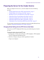
Preparing the Server for the Cluster Service
Before you configure the cluster service, you need to complete the tasks in the following
procedures:
•
“Changing Default Settings for the ATTO Card on Each Node” on page 33
•
“Changing Windows Server Settings on Each Node” on page 36
•
“Renaming the Local Area Network Interface on Each Node” on page 36
•
“Configuring the Private Network Adapter on Each Node” on page 39
•
“Configuring the Binding Order Networks on Each Node” on page 43
•
“Configuring the Public Network Adapter on Each Node” on page 44
•
“Configuring the Cluster Shared-Storage RAID Disks on Each Node” on page 45
The tasks in this section do not require the administrative privileges needed for Microsoft cluster
creation (see “Requirements for Domain User Accounts” on page 27).
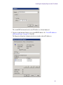
Changing Default Settings for the ATTO Card on Each Node
You need to use the ATTO Configuration Tool to change some default settings on each node in
the cluster.
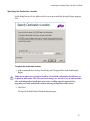
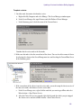
To change the default settings for the ATTO card:
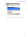
1. On the first node, click Start, and select Programs > ATTO ConfigTool > ATTO ConfigTool.
The ATTO Configuration Tool dialog box opens.
2. In the Device Listing tree (left pane), click the expand box for “localhost.”
A login screen is displayed.
33
Preparing the Server for the Cluster Service
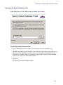
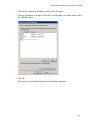
3. Type the user name and password for a local administrator account and click Login.
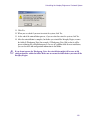
4. In the Device Listing tree, navigate to the appropriate channel on your host adapter.
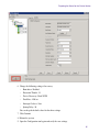
5. Click the NVRAM tab.
34
Preparing the Server for the Cluster Service
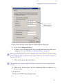
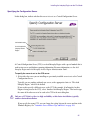
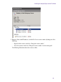
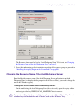
6. Change the following settings if necessary:
-
Boot driver: Enabled.
-
Execution Throttle: 32
-
Device Discovery: Node WWN
-
Data Rate: 4 Gb/sec
-
Interrupt Coalesce: Low
-
Spinup Delay: 30
You can keep the default values for the other settings.
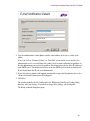
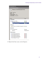
7. Click Commit.
8. Reboot the system.
9. Open the Configuration tool again and verify the new settings.
35
Preparing the Server for the Cluster Service
10. On the other node, repeat steps 1 through 6.
Changing Windows Server Settings on Each Node
The latest image for the AS3000 Windows Server 2008 R2 Standard x64 (Rev. 4, October 17,
2012) includes system settings that previously required manual changes. For information about
these settings, see “Windows Server Settings Included in Latest Image” on page 112.
n
n
Disabling IPv6 completely is no longer recommended. IPv6 is enabled in the Rev. 4 image.
Binding network interface cards (NICs) to IPv6 is not recommended.
At the first boot after installing the Rev. 4 image, unique GUIDs are assigned to the network
adapters used by the failover cluster. The registry might show the same GUID on different
servers. This GUID is not used and you can ignore it.
Renaming the Local Area Network Interface on Each Node
You need to rename the LAN interface on each node to appropriately identify each network.
Although you can use any name for the network connections, Avid suggests that you use the
naming conventions provided in the table in the following procedure.
Avid recommends that you use the same name on both nodes. Make sure the names and network
connections on one node match the names and network connections on the other.
To rename the local area network connections:
1. On node 1, click Start > Control Panel > Network and Sharing Center.
The Network and Sharing Center window opens.
2. Click “Change adapter settings” on the left side of the window.
The Network Connections window opens.
36
Preparing the Server for the Cluster Service
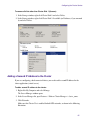
n
The top left network connector on the AS3000 (number 1) is not used and can be disabled. To
disable it, select the corresponding Local Area Connection entry and select File > Disable.
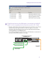
3. Determine which numbered connection (physical port) refers to which device name. You can
determine this by connecting one interface at a time. For example, you can start by
determining which connection refers to the lower left network connection (the heartbeat
connection numbered 3 on AS3000 back panel).
Use the following illustration and table for reference. The illustration uses connections in a
dual-connected Avid ISIS environment as an example.
Interplay Engine Cluster Node 1
AS3000 Back Panel
1
2
33
4 4
Ethernet to ISIS left subnet
Ethernet to ISIS right subnet
Fibre Channel
to Infortrend
Ethernet to node 2
(Private network)
37
Preparing the Server for the Cluster Service
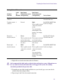
Naming Network Connections
Label
New Names
on
(Redundant-switch
AS3000 configuration)
New Names
(Dual-connected
configuration)
1
Not used
Not used
Intel(R) 82567LM-4 Gigabit
Network Connection
Top right network 2
connector
Not used
Right
Intel(R) PRO/1000 PT Dual
Port Server Adapter
Network
Interface
Top left network
connector
This is a public network
connected to network
switch.
Device Name
You can include the
subnet number of the
interface. For example,
Right-10.
Bottom left
3
network connector
Private
Private
This is a private network
used for the heartbeat
between the two nodes in
the cluster.
This is a private network
used for the heartbeat
between the two nodes
in the cluster.
Bottom right
4
network connector
Public
Left
This is a public network This is a public network
connected to a network connected to network
switch
switch.
Intel(R) 82574L Gigabit
Network Connection
Intel(R) PRO/1000 PT Dual
Port Server Adapter
You can include the
subnet number of the
interface. For example,
Left-20.
4. Right-click a network connections and select Rename.
c
Avid recommends that both nodes use identical network interface names. Although you can
use any name for the network connections, Avid suggests that you use the naming
conventions provided in the previous table.
5. Depending on your Avid network and the device you selected, type a new name for the
network connection and press Enter.
6. Repeat steps 4 and 5 for each network connection.
38
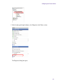
Preparing the Server for the Cluster Service
The following Network Connections window shows the new names used in a dual-connected
Avid ISIS environment.
7. Close the Network Connections window.
8. Repeat this procedure on node 2, using the same names that you used for node 1.
Configuring the Private Network Adapter on Each Node
Repeat this procedure on each node.
To configure the private network adapter for the heartbeat connection:
1. On node 1, click Start > Control Panel > Network and Sharing Center.
The Network and Sharing Center window opens.
2. Click “Change adapter settings” on the left side of the window.
The Network Connections window opens.
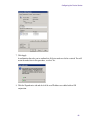
3. Right-click the Private network connection (Heartbeat) and select Properties.
The Private Properties dialog box opens.
4. On the Networking tab, click the following check box:
-
Internet Protocol Version 4 (TCP/IPv4)
Uncheck all other components.
39
Preparing the Server for the Cluster Service
Select this check box.
All others are unchecked.
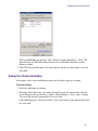
5. Select Internet Protocol Version 4 (TCP/IPv4) and click Properties.
The Internet Protocol Version 4 (TCP/IPv4) Properties dialog box opens.
40
Preparing the Server for the Cluster Service
Type the private IP
address for the node
you are configuring.
6. On the General tab of the Internet Protocol (TCP/IP) Properties dialog box:
n
a.
Select “Use the following IP address.”
b.
IP address: type the IP address for the Private network connection for the node you are
configuring. See “List of IP Addresses and Network Names” on page 29.
When performing this procedure on the second node in the cluster, make sure you assign a static
private IP address unique to that node. In this example, node 1 uses 192.168.100.1 and node 2
uses 192. 168. 100. 2.
c.
n
Subnet mask: type the subnet mask address
Make sure you use a completely different IP address scheme from the one used for the public
network.
d. Make sure the “Default gateway” and “Use the Following DNS server addresses” text
boxes are empty.
7. Click Advanced.
The Advanced TCP/IP Settings dialog box opens.
41
Preparing the Server for the Cluster Service
8. On the DNS tab, make sure no values are defined and that the “Register this connection’s
addresses in DNS” and “Use this connection’s DNS suffix in DNS registration” are not
selected.
9. On the WINS tab, do the following:
t
Make sure no values are defined in the WINS addresses area.
t
Make sure “Enable LMHOSTS lookup” is selected.
t
Select “Disable NetBIOS over TCP/IP.”
10. Click OK.
A message might by displayed stating “This connection has an empty primary WINS
address. Do you want to continue?” Click Yes.
11. Repeat this procedure on node 2, using the static private IP address for that node.
42
Preparing the Server for the Cluster Service
Configuring the Binding Order Networks on Each Node
Repeat this procedure on each node and make sure the configuration matches on both nodes.
To configure the binding order networks:
1. On node 1, click Start > Control Panel > Network and Sharing Center.
The Network and Sharing Center window opens.
2. Click “Change adapter settings” on the left side of the window.
The Network Connections window opens.
3. From the Advanced menu, select Advanced Settings.
The Advanced Settings dialog box opens.
43
Preparing the Server for the Cluster Service
4. In the Connections area, use the arrow controls to position the network connections in the
following order:
-
-
For a redundant-switch configuration in an Avid ISIS environment, use the following
order:
-
Public
-
Private
For a dual-connected configuration in an Avid ISIS environment, use the following
order, as shown in the illustration:
-
Left
-
Right
-
Private
5. Click OK.
6. Repeat this procedure on node 2 and make sure the configuration matches on both nodes.
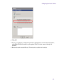
Configuring the Public Network Adapter on Each Node
Make sure you configure the IP address network interfaces for the public network adapters as
you normally would. For examples of public network settings, see “List of IP Addresses and
Network Names” on page 29.
Avid recommends that you disable IPv6 for the public network adapters, as shown in the
following illustration:
44
Preparing the Server for the Cluster Service
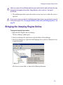
Configuring the Cluster Shared-Storage RAID Disks on Each Node
Both nodes must have the same configuration for the cluster shared-storage RAID disk. When
you configure the disks on the second node, make sure the disks match the disk configuration
you set up on the first node.
n
Make sure the disks are Basic and not Dynamic.
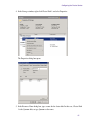
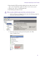
To configure the shared-storage RAID disks on each node:
1. Shut down the server node you are not configuring at this time.
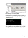
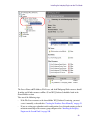
2. Open the Disk Management tool in one of the following ways:
t
Right-click My Computer and select Manage. In the Server Manager list, select Storage
> Disk Management.
t
Click Start, type Disk, and select “Create and format hard drive.”
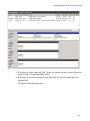
The Disk Management window opens. The following illustration shows the shared storage
drives labeled Disk 1, Disk 2, and Disk 3. In this example they are offline, not initialized,
and unformatted.
45
Preparing the Server for the Cluster Service
3. If the disks are offline, right-click Disk 1 (in the left column) and select Online. Repeat this
action for Disk 3. Do not bring Disk 2 online.
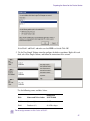
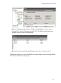
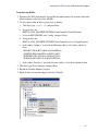
4. If the disks are not already initialized, right-click Disk 1 (in the left column) and select
Initialize Disk.
The Initialize Disk dialog box opens.
46
Preparing the Server for the Cluster Service
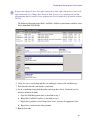
Select Disk 1 and Disk 3 and make sure that MBR is selected. Click OK.
5. Use the New Simple Volume wizard to configure the disks as partitions. Right-click each
disk, select New Simple Volume, and follow the instructions in the wizard.
Use the following names and drive letters:
n
Disk
Name and Drive Letter
Infortrend
S12F-R1440
Disk 1
Quorum (Q:)
10 GB
Disk 3
Databases (S:)
814 GB or larger
Do not assign a name or drive letter to Disk 2.
47
Preparing the Server for the Cluster Service
n
If you need to change the drive letter after running the wizard, right-click the drive letter in the
right column and select Change Drive Letter or Path. If you receive a warning tells you that
some programs that rely on drive letters might not run correctly and asks if you want to continue.
Click Yes.
The following illustration shows Disk 1 and Disk 3 with the required names and drive letters
for the Infortrend S12F-R1440:
6. Verify you can access the disk and that it is working by creating a file and deleting it.
7. Shut down the first node and start the second node.
8. On the second node, bring the disks online and assign drive letters. You do not need to
initialize or format the disks.
a.
Open the Disk Management tool, as described in step 2.
b.
Bring Disk 1 and Disk 3 online, as described in step 3.
c.
Right-click a partition, select Change Drive Letter, and enter the appropriate letter.
d. Repeat these actions for the other partitions.
9. Boot the first node.
48
Configuring the Cluster Service
10. Open the Disk Management tool to make sure that the disks are still online and have the
correct drive letters assigned.
At this point, both nodes should be running.
Configuring the Cluster Service
Take the following steps to configure the cluster service:
1. Add the servers to the domain. See “Joining Both Servers to the Active Directory Domain”
on page 49.
2. Install the Failover Clustering feature. See “Installing the Failover Clustering Feature” on
page 49.
3. Start the Create Cluster Wizard on the first node. See “Creating the Cluster Service” on
page 52. This procedure creates the cluster service for both nodes.
4. Rename the cluster networks. See “Renaming the Cluster Networks in the Failover Cluster
Manager” on page 58.
5. Rename and delete the cluster disks. See “Renaming Cluster Disk 1 and Deleting the
Remaining Cluster Disks” on page 60.
6. For a dual-connected configuration, add a second IP address. See “Adding a Second IP
Address to the Cluster” on page 62.
7. Test the failover. See “Testing the Cluster Installation” on page 67.
c
Creating the cluster service requires an account with particular administrative privileges.
For more information, see “Requirements for Domain User Accounts” on page 27.
Joining Both Servers to the Active Directory Domain
After configuring the network information, join the two servers to the Active Directory domain.
Each server requires a reboot to complete this process. At the login window, use the domain
administrator account (see “Requirements for Domain User Accounts” on page 27).
Installing the Failover Clustering Feature
The Failover Clustering feature is a Windows Server 2008 feature that contains the complete
Failover functionality.
The Failover Cluster Manager, which is a snap-in to the Server Manager, is installed as part of
the Failover Clustering installation.
49
Configuring the Cluster Service
To install the Failover Clustering featurer:
1. On the first node, right-click My Computer and select Manage.
The Server Manager window opens.
2. In the Server Manager list, click Features.
3. On the right-side of the Features window, click Add Features.
A list of features is displayed.
n
If a list of Features does not display and “Error” is displayed instead, see “Displaying the List
of Server Features” on page 51.
4. Select Failover Clustering from the list of features and click Next.
5. On the next screen, click Install.
The Failover Cluster Manager installation program starts. At the end of the installation, a
message states that the installation was successful.
6. Click Close.
50
Configuring the Cluster Service
To check if the feature was installed, open the Server Manager and open Features. The
Failover Cluster Manager should be displayed.
7. Repeat this procedure on the second node.
Displaying the List of Server Features
If a list of server features does not display and “Error” is displayed instead, change the Default
Authentication Level as described in the following procedure.
To display the list of server features:
1. Click Start, the select Administrative Tools > Component Services.
2. In the directory tree, expand Component Services, expand Computers, right-click My
Computer, and select Properties.
3. Click the Default Properties tab.
4. In the Default Distributed COM Communication Properties section, change the Default
Authentication Level from None to Connect.
51
Configuring the Cluster Service
5. Click OK.
Creating the Cluster Service
To create the cluster service:
1. Make sure all storage devices are turned on.
2. Log in to the operating system using the cluster installation account (see “Requirements for
Domain User Accounts” on page 27).
3. On the first node, right-click My Computer and select Manage.
The Server Manager window opens.
4. In the Server Manager list, open Features and click Failover Cluster Manager.
52
Configuring the Cluster Service
5. Click Create a Cluster.
The Create Cluster Wizard opens with the Before You Begin window.
6. Review the information and click Next (you will validate the cluster in a later step).
7. In the Select Servers window, type the simple computer name of node 1 and click Add. Then
type the computer name of node 2 and click Add. The Cluster Wizard checks the entries and,
if the entries are valid, lists the fully qualified domain names in the list of servers, as shown
in the following illustration:
53
Configuring the Cluster Service
c
If you cannot add the remote node to the cluster, and receive an error message “Failed to
connect to the service manager on <computer-name>,” check the following:
- Make sure that the time settings for both nodes are in sync.
- Make sure that the login account is a domain account with the required privileges.
- Make sure the Remote Registry service is enabled.
For more information, see “Before You Begin the Server Failover Installation” on page 34.
8. Click Next.
The Validation Warning window opens.
9. Select Yes and click Next several times. When you can select a testing option, select Run All
Tests.
The automatic cluster validation tests begin. The tests can take up to twenty minutes. After
running these validation tests and receiving notification that the cluster is valid, you are
eligible for technical support from Microsoft.
The following tests display warnings, which you can ignore:
-
Validate SCSI device Vital Product Data (VPD)
-
Validate All Drivers Signed
-
Validate Memory Dump Settings
10. In the Access Point for Administering the Cluster window, type a name for the cluster, then
click in the Address text box and enter an IP address.
54
Configuring the Cluster Service
If you are configuring a dual-connected cluster, you need to add a second IP address after
renaming and deleting cluster disks. This procedure is described in “Adding a Second IP
Address to the Cluster” on page 62.
11. Click Next.
A message informs you that the system is validating settings. At the end of the process, the
Confirmation window opens.
55
Configuring the Cluster Service
12. Review the information and if it is correct, click Next.
The Create Cluster Wizard creates the cluster. At the end of the process, a Summary window
opens and displays information about the cluster.
You can click View Report to see a log of the entire cluster creation.
13. Click Finish.
Now when you open the Failover Cluster Manager in the Server Manager, the cluster you
created and information about its components are displayed, including the networks
available to the cluster (cluster networks).
The following illustration shows components of a dual-connected cluster. Cluster Network 1
and Cluster Network 2 are external networks connected to VLAN 10 and VLAN 20 on Avid
ISIS, and Cluster Network 3 is a private, internal network for the heartbeat.
56
Configuring the Cluster Service
It is possible that Cluster Network 2 (usually Right or VLAN 20) is not configured to be
external by the Create Cluster Wizard. In this case, right-click Cluster Network 2, select
Properties, and check “Allow clients to connect through this network.”
The following illustration shows components of a cluster in a redundant-switch ISIS
environment. Cluster Network 1 is an external network connecting to one of the redundant
switches, and Cluster Network 2 is a private, internal network for the heartbeat.
57
Configuring the Cluster Service
Renaming the Cluster Networks in the Failover Cluster Manager
You can more easily manage the cluster by renaming the networks that are listed under the
Failover Cluster Manager.
To rename the networks:
1. Right-click My Computer and select Manage.
The Server Manager window opens.
2. In the Server Manager list, open Features > Failover Cluster Manager > cluster_name.
3. Click Networks.
4. In the Networks window, right-click Cluster Network 1 and select Properties.
The Properties dialog box opens.
5. Click in the Name text box, and type a meaningful name, for example, a name that matches
the name you used in the TCP/IP properties. For a redundant-switch configuration, use
Public. For a dual-connected configuration, use Left, as shown in the following example. For
this network, keep the option “Allow clients to connect through this network.”
58
Configuring the Cluster Service
6. Click OK.
7. If you are configuring a dual-connected cluster configuration, rename Cluster Network 2,
using Right. For this network, keep the option “Allow clients to connect through this
network.”
8. Rename the other network Private. This network is used for the heartbeat.
59
Configuring the Cluster Service
For this private network, leave the option “Allow clients to connect through this network”
unchecked.
Renaming Cluster Disk 1 and Deleting the Remaining Cluster Disks
You can more easily manage the cluster by renaming Cluster Disk 1, which is listed under the
Failover Cluster Manager.
You must delete any disks other than Cluster Disk 1 that are listed. In this operation, deleting the
disks means removing them from cluster control. After the operation, the disks are labeled
offline in the Disk Management tool. This operation does not delete any data on the disks.
c
c
Cluster Disk 2 is not used. You bring the Databases (S:) drive back online in a later step
(“Bringing the Shared Database Drive Online” on page 72).
Before renaming or deleting disks, make sure you select the correct disk by checking the
drive letter, either in the Properties dialog box or by expanding Cluster Disks in the
Summary of Storage screen.
To rename Cluster Disk 1:
1. Right-click My Computer and select Manage.
The Server Manager window opens.
2. In the Server Manager list, open Features > Failover Cluster Manager > cluster_name.
3. Click Storage.
60
Configuring the Cluster Service
4. In the Storage window, right-click Cluster Disk 1 and select Properties.
The Properties dialog box opens.
5. In the Resource Name dialog box, type a name for the cluster disk. In this case, Cluster Disk
1 is the Quorum disk, so type Quorum as the name.
61
Configuring the Cluster Service
To remove all disks other than Cluster Disk 1 (Quorum)
1. In the Storage window, right-click Cluster Disk 2 and select Delete.
2. In the Storage window, right-click Cluster Disk 3 if available (or Databases, if you renamed
it) and select Delete.
Adding a Second IP Address to the Cluster
If you are configuring a dual-connected cluster, you need to add a second IP address for the
cluster application (virtual server).
To add a second IP address to the cluster:
1. Right-click My Computer and select Manage.
The Server Manager window opens.
2. In the Server Manager list, open Features > Failover Cluster Manager > cluster_name.
3. Click Networks.
Make sure that Cluster Use is enabled for both ISIS networks, as shown in the following
illustration.
62
Configuring the Cluster Service
If a network is not enabled, right-click the network, select Properties, and select “Allow
clients to connect through this network.”
4. In the Failover Cluster Manager, select the cluster application by clicking on the Cluster
name in the left column of the Failover Cluster Manager.
63
Configuring the Cluster Service
5. In the Actions panel (right column), select Properties in the Name section.
The Properties dialog box opens.
64
Configuring the Cluster Service
In the network column, if <unknown network> or <No Network> is displayed instead of the
network identifier, close the Server Manager window, and after waiting a few seconds open
it again.
6. In the General tab, do the following:
a.
Click Add.
b.
Type the IP address for the other ISIS network.
c.
Click OK.
The General tab shows the IP addresses for both ISIS networks.
65
Configuring the Cluster Service
7. Click Apply.
A confirmation box asks you to confirm that all cluster nodes need to be restarted. You will
restart the nodes later in this procedure, so select Yes.
8. Click the Dependencies tab and check if the new IP address was added with an OR
conjunction.
66
Configuring the Cluster Service
If the second IP address is not there, click “Click here to add a dependency.” Select “OR”
from the list in the AND/OR column and select the new IP address from the list in the
Resource column.
9. Click OK and restart both nodes. Start with node one and after it is back online, restart the
other node.
Testing the Cluster Installation
At this point, test the cluster installation to make sure the failover process is working.
To test the failover:
1. Make sure both nodes are running.
2. Determine which node is the active node (the node that owns the quorum disk). Open the
Server Manager and select Features > Failover Cluster Manager > cluster_name > Storage.
The server that owns the Quorum disk is the active node.
In the following figure, warrm-ipe3 (node 1) is the current owner of the Quorum disk and is
the active node.
67
Configuring the Cluster Service
3. Open a Command Prompt and enter the following command:
cluster group “Cluster Group” /move:node_hostname
This command moves the cluster group, including the Quorum disk, to the node you specify.
To test the failover, use the hostname of the non-active node. The following illustration
shows the command and result if the non-active node (node 2) is named warrm-ipe4. The
status “Partially Online” is normal.
4. Open the Server Manager and select Features > Failover Cluster Manager > cluster_name >
Storage. Make sure that the Quorum disk is online and that current owner is node 2, as
shown in the following illustration.
68
Configuring the Cluster Service
5. In the Server Manager, select Features > Failover Cluster Manager > cluster_name >
Networks. The status of all networks should be “Up.” The following illustration shows
networks for a dual-connected configuration.
6. Repeat the test by using the Command Prompt to move the cluster back to node 1.
Configuration of the cluster service on all nodes is complete and the cluster is fully operational.
You can now install the Interplay Engine.
69
3 Installing the Interplay Engine for a
Failover Cluster
After you set up and configure the cluster, you need to install the Interplay Engine software on
both nodes. The following topics describe installing the Interplay Engine and other final tasks:
•
Disabling Any Web Servers
•
Installing the Interplay Engine on the First Node
•
Installing the Interplay Engine on the Second Node
•
Bringing the Interplay Engine Online
•
Testing the Complete Installation
•
Updating a Clustered Installation (Rolling Upgrade)
•
Uninstalling the Interplay Engine on a Clustered System
The tasks in this chapter do not require the domain administrator privileges that are required
when creating the Microsoft cluster (see “Requirements for Domain User Accounts” on
page 27).
Disabling Any Web Servers
The Interplay Engine uses an Apache web server that can only be registered as a service if no
other web server (for example, IIS) is serving the port 80 (or 443). Stop and disable or uninstall
any other http services before you start the installation of the server. You must perform this
procedure on both nodes.
n
No action should be required, because the only web server installed at this point is the IIS and it
should already be disabled in the server image (see “Windows Server Settings Included in Latest
Image” on page 112).
Installing the Interplay Engine on the First Node
Installing the Interplay Engine on the First Node
The following sections provide procedures for installing the Interplay Engine on the first node.
For a list of example entries, see “List of IP Addresses and Network Names” on page 29.
c
•
“Preparation for Installing on the First Node” on page 71
•
“Starting the Installation and Accepting the License Agreement” on page 74
•
“Installing the Interplay Engine Using Custom Mode” on page 74
•
“Checking the Status of the Resource Group” on page 89
•
“Creating the Database Share Manually” on page 91
•
“Adding a Second IP Address (Dual-Connected Configuration)” on page 92
Shut down the second node while installing Interplay Engine for the first time.
Preparation for Installing on the First Node
You are ready to start installing the Interplay Engine on the first node. During setup you must
enter the following cluster-related information:
•
Virtual IP Address: the Interplay Engine service IP address of the resource group. For a list
of example names, see “List of IP Addresses and Network Names” on page 29.
•
Subnet Mask: the subnet mask on the local network.
•
Public Network: the name of the public network connection.
-
For a redundant-switch ISIS configuration, type Public or whatever name you assigned
in “Renaming the Local Area Network Interface on Each Node” on page 36.
-
For a dual-connection ISIS configuration, type Left-subnet or whatever name you
assigned in “Renaming the Cluster Networks in the Failover Cluster Manager” on
page 58. For a dual-connection configuration, you set the other public network
connection after the installation. See “Checking the Status of the Resource Group” on
page 89.
To check the public network connection on the first node, open the Networks view in the
Failover Cluster Manager and look up the name there.
•
Shared Drive: the letter for the shared drive that holds the database. Use S: for the shared
drive letter. You need to make sure this drive is online. See “Bringing the Shared Database
Drive Online” on page 72.
•
Cluster Service Account User and Password (Server Execution User): the domain account
that is used to run the cluster. See “Before You Begin the Server Failover Installation” on
page 27.
71
Installing the Interplay Engine on the First Node
c
n
Shut down the second node when installing Interplay Engine for the first time.
When installing the Interplay Engine for the first time on a machine with cluster services, you
are asked to choose between clustered and regular installation. The installation on the second
node (or later updates) reuses the configuration from the first installation without allowing you
to change the cluster-specific settings. In other words, it is not possible to change the
configuration settings without uninstalling the Interplay Engine.
Bringing the Shared Database Drive Online
You need to make sure that the shared database drive (S:) is online.
To bring the shared database drive online:
1. Shut down the second node.
2. Open the Disk Management tool in one of the following ways:
t
Right-click My Computer and select Manage. In the Server Manager list, select Storage
> Disk Management.
t
Click Start, type Disk, and select “Create and format hard drive.”
The Disk Management window opens. The following illustration shows the shared storage
drives labeled Disk 1, Disk 2, and Disk 3. Disk 1 is online, Disk 2 is not formatted and is
offline (not used), and Disk 3 is formatted but offline.
72
Installing the Interplay Engine on the First Node
If Disk 3 is online, you can skip the following steps.
3. Right-click Disk 3 (in the left column) and select Online.
4. Make sure the drive letter is correct (S:) and the drive is named Databases. If not, you can
change it here. Right-click the disk name and letter (right-column) and select Change Drive
Letter or Path.
73
Installing the Interplay Engine on the First Node
If you attempt to change the drive letter, you receive a warning tells you that some programs
that rely on drive letters might not run correctly and asks if you want to continue. Click Yes.
Starting the Installation and Accepting the License Agreement
To start the installation:
1. Make sure the second node is shut down.
2. Insert the Avid Interplay Servers installation flash drive.
A start screen opens.
3. Select the following from the Interplay Server Installer Main Menu:
Servers > Avid Interplay Engine > Avid Interplay Engine
The Welcome dialog box opens.
4. Close all Windows programs before proceeding with the installation.
5. Information about the installation of Apache is provided in the Welcome dialog box. Read
the text and then click Next.
The License Agreement dialog box opens.
6. Read the license agreement information and then accept the license agreement by selecting
“I accept the agreement.” Click Next.
The Specify Installation Type dialog box opens.
7. Continue the installation as described in the next topic.
c
If you receive a message that the Avid Workgroup Name resource was not found, you need
to check the registry. See “Changing the Resource Name of the Avid Workgroup Server” on
page 98.
Installing the Interplay Engine Using Custom Mode
The first time you install the Interplay Engine on a cluster system, you should use the Custom
installation mode. This lets you specify all the available options for the installation. This is the
recommended option to use.
The following procedures are used to perform a Custom installation of the Interplay Engine:
•
“Specifying Cluster Mode During a Custom Installation” on page 75
•
“Specifying the Interplay Engine Details” on page 76
•
“Specifying the Interplay Engine Service Name” on page 78
•
“Specifying the Destination Location” on page 79
•
“Specifying the Default Database Folder” on page 80
74
Installing the Interplay Engine on the First Node
•
“Specifying the Share Name” on page 81
•
“Specifying the Configuration Server” on page 82
•
“Specifying the Server User” on page 83
•
“Specifying the Server Cache” on page 84
•
“Enabling Email Notifications” on page 85
•
“Installing the Interplay Engine for a Custom Installation on the First Node” on page 87
For information about updating the installation, see “Updating a Clustered Installation (Rolling
Upgrade)” on page 105.
Specifying Cluster Mode During a Custom Installation
To specify cluster mode:
1. In the Specify Installation Type dialog box, select Custom.
2. Click Next.
The Specify Cluster Mode dialog box opens.
75
Installing the Interplay Engine on the First Node
3. Select Cluster and click Next to continue the installation in cluster mode.
The Specify Interplay Engine Details dialog box opens.
Specifying the Interplay Engine Details
In this dialog box, provide details about the Interplay Engine.
76
Installing the Interplay Engine on the First Node
To specify the Interplay Engine details:
1. Type the following values:
-
Virtual IP address: This is the Interplay Engine service IP Address, not the Cluster
service IP address. For a list of examples, see “List of IP Addresses and Network
Names” on page 29.
For a dual-connected configuration, you set the other public network connection after
the installation. See “Adding a Second IP Address (Dual-Connected Configuration)” on
page 92.
-
Subnet Mask: The subnet mask on the local network.
-
Public Network: For a redundant-switch ISIS configuration, type Public or whatever
name you assigned in “Renaming the Local Area Network Interface on Each Node” on
page 36. For a dual-connected ISIS configuration, type the name of the public network
on the first node, for example, Left, or whatever name you assigned in “Renaming the
Cluster Networks in the Failover Cluster Manager” on page 58. This must be the cluster
resource name.
To check the name of the public network on the first node, open the Networks view in
the Failover Cluster Manager and look up the name there.
-
c
Shared Drive: The letter of the shared drive that is used to store the database. Use S: for
the shared drive letter.
Make sure you type the correct information here, as this data cannot be changed
afterwards. Should you require any changes to the above values later, you will need to
uninstall the server on both nodes.
2. Click Next.
The Specify Interplay Engine Name dialog box opens.
77
Installing the Interplay Engine on the First Node
Specifying the Interplay Engine Service Name
In this dialog box, type the name of the Interplay Engine service.
To specify the Interplay Engine name:
1. Specify the public names for the Avid Interplay Engine service by typing the following
values:
-
The Network Name will be associated with the virtual IP Address that you entered in the
previous Interplay Engine Details dialog box. This is the Interplay Engine service name
(see “List of IP Addresses and Network Names” on page 29). It must be a new, unused
name, and must be registered in the DNS so that clients can find the server without
having to specify its address.
-
The Server Name is used by clients to identify the server. If you only use Avid Interplay
Clients on Windows computers, you can use the Network Name as the server name. If
you use several platforms as client systems, such as Macintosh® and Linux® you need to
specify the static IP address that you entered for the resource group in the previous
dialog box. Macintosh systems are not always able to map server names to IP addresses.
If you type a static IP address, make sure this IP address is not provided by a DHCP
server.
2. Click Next.
The Specify Destination Location dialog box opens.
78
Installing the Interplay Engine on the First Node
Specifying the Destination Location
In this dialog box specify the folder in which you want to install the Interplay Engine program
files.
To specify the destination location:
1. Avid recommends that you keep the default path C:\Program Files\Avid\Avid Interplay
Engine.
c
Under no circumstances attempt to install to a shared disk; independent installations are
required on both nodes. This is because local changes are also necessary on both machines.
Also, with independent installations you can use a rolling upgrade approach later,
upgrading each node individually without affecting the operation of the cluster.
2. Click Next.
The Specify Default Database Folder dialog box opens.
79
Installing the Interplay Engine on the First Node
Specifying the Default Database Folder
In this dialog box specify the folder where the database data is stored.
To specify the default database folder:
1. Type S:\Workgroup_Databases. Make sure the path specifies the shared drive (S:).
This folder must reside on the shared drive that is owned by the resource group of the server.
You must use this shared drive resource so that it can be monitored and managed by the
cluster service. The drive must be assigned to the physical drive resource that is mounted
under the same drive letter on the other machine.
2. Click Next.
The Specify Share Name dialog box opens.
80
Installing the Interplay Engine on the First Node
Specifying the Share Name
In this dialog box specify a share name to be used for the database folder.
To specify the share name:
1. Accept the default share name.
Avid recommends you use the default share name WG_Database$. This name is visible on
all client platforms, such as Windows NT Windows 2000 and Windows XP.The “$” at the
end makes the share invisible if you browse through the network with the Windows
Explorer. For security reasons, Avid recommends using a “$” at the end of the share name. If
you use the default settings, the directory S:\Workgroup_Databases is accessible as
\\InterplayEngine\WG_Database$.
2. Click Next.
This step takes a few minutes. When finished the Specify Configuration Server dialog box
opens.
81
Installing the Interplay Engine on the First Node
Specifying the Configuration Server
In this dialog box, indicate whether this server is to act as a Central Configuration Server.
Set for both nodes.
Use this option for
Interplay Archive
Engine
A Central Configuration Server (CCS) is an Avid Interplay Engine with a special module that is
used to store server and database-spanning information. For more information, see the Avid
Interplay Engine and Avid Interplay Archive Engine Administration Guide.
To specify the server to act as the CCS server:
1. Select either the server you are installing or a previously installed server to act as the Central
Configuration Server.
Typically you are working with only one server, so the appropriate choice is “This Avid
Interplay Engine,” which is the default.
If you need to specify a different server as the CCS (for example, if an Interplay Archive
Engine is being used as the CCS), select “Another Avid Interplay Engine.” You need to type
the name of the other server to be used as the CCS in the next dialog box.
c
Only use a CCS that is at least as high availability as this cluster installation, typically
another clustered installation.
If you specify the wrong CCS, you can change the setting later on the server machine in the
Windows Registry. See “Automatic Server Failover Tips and Rules” on page 110.
82
Installing the Interplay Engine on the First Node
2. Click Next.
The Specify Server User dialog box opens.
Specifying the Server User
In this dialog box, define the Cluster Service account (Server Execution User) used to run the
Avid Interplay Engine.
The Server Execution User is the Windows domain user that runs the Interplay Engine and the
cluster service. This account is automatically added to the Local Administrators group on the
server. This account must be the one that was used to set up the cluster service. See “Before You
Begin the Server Failover Installation” on page 27.
To specify the Server Execution User:
1. Type the Cluster Service Account user login information.
c
c
The installer cannot check the username or password you type in this dialog. Make sure
that the password is set correctly, or else you will need to uninstall the server and repeat the
entire installation procedure. Avid does not recommend changing the Server Execution
User in cluster mode afterwards, so choose carefully.
When typing the domain name do not use the full DNS name such as
mydomain.company.com, because the DCOM part of the server will be unable to start. You
should use the NetBIOS name, for example, mydomain.
83
Installing the Interplay Engine on the First Node
2. Click Next.
The Specify Preview Server Cache dialog box opens.
If necessary, you can change the name of the Server Execution User after the installation. For
more information, see “Troubleshooting the Server Execution User Account” and “Re-creating
the Server Execution User” in the Avid Interplay Engine and Avid Interplay Archive Engine
Administration Guide and the Interplay ReadMe.
Specifying the Server Cache
In this dialog box, specify the path for the cache folder.
n
For more information on the Preview Server cache and Preview Server configuration, see “Avid
Workgroup Preview Server Service” in the Avid Interplay Engine and Avid Interplay Archive
Engine Administration Guide.
To specify the server cache folder:
1. Type or browse to the path of the server cache folder. Typically, the default path is used.
2. Click Next.
The Enable Email Notification dialog box opens if you are installing the Avid Interplay
Engine for the first time.
84
Installing the Interplay Engine on the First Node
Enabling Email Notifications
The first time you install the Avid Interplay Engine, the Enable Email Notification dialog box
opens. The email notification feature sends emails to your administrator when special events,
such as “Cluster Failure,” “Disk Full,” and “Out Of Memory” occur. Activate email notification
if you want to receive emails on special events, server or cluster failures.
To enable email notification:
1. (Option) Select Enable email notification on server events.
The Email Notification Details dialog box opens.
85
Installing the Interplay Engine on the First Node
2. Type the administrator's email address and the email address of the server, which is the
sender.
If an event, such as “Resource Failure” or “Disk Full” occurs on the server machine, the
administrator receives an email from the sender's email account explaining the problem, so
that the administrator can react to the problem. You also need to type the static IP address of
your SMTP server. The notification feature needs the SMTP server in order to send emails.
If you do not know this IP, ask your administrator.
3. If you also want to inform Avid Support automatically using email if problems arise, select
“Send critical notifications also to Avid Support.”
4. Click Next.
The installer modifies the file Config.xml in the Workgroup_Data\Server\Config\Config
directory with your settings. If you need to change these settings, edit Config.xml.
The Ready to Install dialog box opens.
86
Installing the Interplay Engine on the First Node
Installing the Interplay Engine for a Custom Installation on the First Node
In this dialog box, begin the installation of the engine software.
To install the Interplay Engine software:
1. Click Next.
Use the Back button to review or change the data you have entered. You can also terminate
the installer using the Cancel button, because no changes have been done to the system yet.
The first time you install the software, a dialog box opens and asks if you want to install the
Sentinel driver. This driver is used by the licensing system.
2. Click Continue.
The Installation Completed dialog box opens after the installation is completed.
87
Installing the Interplay Engine on the First Node
The Windows Firewall is turned off by the server image (see “Windows Server Settings
Included in Latest Image” on page 112). If the Firewall is turned on, you get messages that
the Windows Firewall has blocked nxnserver.exe (the Interplay Engine) and the Apache
server from public networks.
If your customer wants to allow communication on public networks, click “Allow access”
and select the check box for “Public networks, such as those in airports and coffee shops.”
88
Installing the Interplay Engine on the First Node
3. Do one of the following:
t
Click Finish.
t
Analyze and resolve any issues or failures reported.
4. Click OK if prompted for a restart the system.
The installation procedure requires the machine to restart (up to twice). For this reason it is
very important that the other node is shut down, otherwise the current node loses ownership
of the Avid Workgroup resource group. This applies to the installation on the first node only.
n
Subsequent installations should be run as described in “Updating a Clustered Installation
(Rolling Upgrade)” on page 105 or in the Avid Interplay ReadMe.
Checking the Status of the Resource Group
After installing the Interplay Engine, check the status of the resources in the Avid Workgroup
Server resource group.
To check the status of the resource group:
1. After the installation is complete, right-click My Computer and select Manage.
The Server Manager window opens.
2. In the Server Manager list, open Features and click Failover Cluster Manager.
3. Open the Avid Workgroup Server resource group.
The list of resources should look similar to those in the following illustration.
89
Installing the Interplay Engine on the First Node
The Server Name and IP Address, File Server, and Avid Workgroup Disk resources should
be online and all other resources offline. S$ and WG_Database$ should be listed in the
Shared Folders section.
Take one of the following steps:
-
If the File Server resource or the shared folder WG_Database$ is missing, you must
create it manually, as described in “Creating the Database Share Manually” on page 91.
-
If you are setting up a redundant-switch configuration, leave this node running so that it
maintains ownership of the resource group and proceed to “Installing the Interplay
Engine on the Second Node” on page 100.
90
Installing the Interplay Engine on the First Node
-
n
If you are setting up an Avid ISIS dual-connected configuration, proceed to “Adding a
Second IP Address (Dual-Connected Configuration)” on page 92.
Avid does not recommend starting the server at this stage, because it is not installed on the other
node and a failover would be impossible.
Creating the Database Share Manually
If the File Server resource or the database share (WG_Database$) is not created (see “Checking
the Status of the Resource Group” on page 89), you can create it manually by using the following
procedure.
c
If you copy the commands and paste them into a Command Prompt window, you must
replace any line breaks with a blank space.
To create the database share and File Server resource manually:
1. In the Failover Cluster Manager, make sure that the “Avid Workgroup Disk” resource (the S:
drive) is online.
2. Open a Command Prompt window.
3. To create the database share, enter the following command:
net share WG_Database$=S:\Workgroup_Databases /UNLIMITED
/GRANT:users,FULL /GRANT:Everyone,FULL /REMARK:"Avid Interplay database
directory" /Y
If the command is successful the following message is displayed:
WG_Database$ was shared successfully.
4. Enter the following command. Substitute the virtual host name of the Interplay Engine
service for ENGINESERVER.
cluster res "FileServer-(ENGINESERVER)(Avid Workgroup Disk)" /priv
MyShare="WG_Database$":str
No message is displayed for a successful command.
5. Enter the following command. Again, substitute the virtual host name of the Interplay
Engine service for ENGINESERVER.
cluster res "Avid Workgroup Engine Monitor"
/adddep:"FileServer-(ENGINESERVER)(Avid Workgroup Disk)"
If the command is successful the following message is displayed:
Making resource 'Avid Workgroup Engine Monitor' depend on resource
'FileServer-(ENGINESERVER)(Avid Workgroup Disk)'...
6. Make sure the File Server resource and the database share (WG_Database$) are listed in the
Failover Cluster Manager (see “Checking the Status of the Resource Group” on page 89).
91
Installing the Interplay Engine on the First Node
Adding a Second IP Address (Dual-Connected Configuration)
If you are setting up an Avid ISIS dual-connected configuration, you need use the Failover
Cluster Manager to add a second IP address.
To add a second IP address:
1. In the Failover Cluster Manager, select Avid Workgroup Server.
2. Bring the Name, IP Address, and File Server resources offline by doing one of the following:
-
Right-click the resource and select “Take this resource offline.”
-
Select all resources and select “Take this resource offline” in the Actions panel of the
Server Manager window.
The following illustration shows the resources offline.
3. Right-click the Name resource and select Properties.
The Properties dialog box opens.
92
Installing the Interplay Engine on the First Node
c
Note that the Resource Name is listed as “Avid Workgroup Name.” Make sure to check the
Resource Name after adding the second IP address and bringing the resources on line in
step 9.
If the Kerberos Status is offline, you can continue with the procedure. After bringing the
server online, the Kerberos Status should be OK.
4. Click the Add button below the IP Addresses list.
The IP Address dialog box opens.
93
Installing the Interplay Engine on the First Node
The second ISIS sub-network and a static IP Address are already displayed.
5. Type the second Interplay Engine service Avid ISIS IP address. See “List of IP Addresses
and Network Names” on page 29. Click OK.
The Properties dialog box is displayed with two networks and two IP addresses.
94
Installing the Interplay Engine on the First Node
6. Check that you entered the IP address correctly, then click Apply.
7. Click the Dependencies tab and check that the second IP address was added, with an OR in
the AND/OR column.
8. Click OK.
The resources screen should look similar to the following illustration.
95
Installing the Interplay Engine on the First Node
9. Bring the Name, both IP addresses, and the File Server resource online by doing one of the
following:
-
Right-click the resource and select “Bring this resource online.”
-
Select the resources and select “Bring this resource online” in the Actions panel.
The following illustration shows the resources online.
96
Installing the Interplay Engine on the First Node
10. Right-click the Name resource and select Properties.
97
Installing the Interplay Engine on the First Node
The Resource Name must be listed as “Avid Workgroup Name.” If it is not, see “Changing
the Resource Name of the Avid Workgroup Server” on page 98.
11. Leave this node running so that it maintains ownership of the resource group and proceed to
“Installing the Interplay Engine on the Second Node” on page 100.
Changing the Resource Name of the Avid Workgroup Server
If you find that the resource name of the Avid Workgroup Server application is not “Avid
Workgroup Name” (as displayed in the properties for the Server Name), you need to change the
name in the Windows registry.
To change the resource name of the Avid Workgroup Server:
1. On the node hosting the Avid Workgroup Server (the active node), open the registry editor
and navigate to the key HKEY_LOCAL_MACHINE\Cluster\Resources.
c
If you are installing a dual-connected cluster, make sure to edit the “Cluster” key. Do not
edit other keys that include the word “Cluster,” such as the “0.Cluster” key.
98
Installing the Interplay Engine on the First Node
2. Browse through the GUID named subkeys looking for the one subkey where the value
“Type” is set to “Network Name” and the value “Name” is set to <incorrect_name>.
3. Change the value “Name” to “Avid Workgroup Name.”
4. Do the following to shut down the cluster:
c
Make sure you have edited the registry entry before you shut down the cluster.
a.
In the Server Manager tree (left panel) select the cluster. In the following example, the
cluster name is muc-vtlasclu1.VTL.local.
b.
In the context menu or the Actions panel on the right side, select “More
Actions > Shutdown Cluster.”
99
Installing the Interplay Engine on the Second Node
5. Do the following to bring the cluster on line:
a.
In the Server Manager tree (left panel) select the cluster.
b.
In the context menu or the Actions panel on the right side, select “Start Cluster Service.”
Installing the Interplay Engine on the Second Node
To install the Interplay Engine on the second node:
1. Leave the first machine running so that it maintains ownership of the resource group and
start the second node.
c
c
Do not attempt to move the resource group over to the second node, or similarly, do not
shut down the first node while the second is up, before the installation is completed on the
second node.
Do not attempt to initiate a failover before installation is completed on the second node and
you create an Interplay database. See “Testing the Complete Installation” on page 103.
2. Perform the installation procedure for the second node as described in “Installing the
Interplay Engine on the First Node” on page 71. In contrast to the installation on the first
node, the installer automatically detects all settings previously entered on the first node.
The Attention dialog box opens.
3. Click OK.
4. The same installation dialog boxes will open that you saw before, except for the cluster
related settings that only need to be entered once. Enter the requested information and allow
the installation to proceed.
100
Bringing the Interplay Engine Online
c
Make sure you use the installation mode that you used for the first node and enter the same
information throughout the installer. Using different values results in a corrupted
installation.
5. The installation procedure requires the machine to restart (up to twice). Allow the restart as
requested.
c
If you receive a message that the Avid Workgroup Name resource was not found, you need
to check the registry. See “Changing the Resource Name of the Avid Workgroup Server” on
page 98.
Bringing the Interplay Engine Online
To bring the Interplay Engine online:
1. Right-click My Computer and select Manage.
The Server Manager window opens.
2. In the Server Manager list, open Features and click Failover Cluster Manager.
3. In the Server Manager tree, right-click Avid Workgroup Server and select “Bring this service
or application online.”
All resources are now online, as shown in the following illustration.
101
After Installing the Interplay Engine
After Installing the Interplay Engine
After you install the Interplay Engine, install the following applications on both nodes:
n
•
Interplay Access: From the Interplay Server Installer Main Menu, select Servers > Avid
Interplay Engine > Avid Interplay Access.
•
Avid ISIS client: See the Avid ISIS System Setup Guide.
If you cannot log in or connect to the Interplay Engine, make sure the database share
WG_Database$ exists. You might get the following error message when you try to log in: “The
network name cannot be found (0x80070043).” For more information, see “Creating the
Database Share Manually” on page 91.
Then create an Interplay database, as described in “Creating an Interplay Database” on page 103.
102
Creating an Interplay Database
Creating an Interplay Database
Before testing the failover cluster, you need to create a database. The following procedure
describes basic information about creating a database. For complete information, see the Avid
Interplay Engine and Avid Interplay Archive Engine Administration Guide.
To create an Interplay database:
1. Start the Interplay Administrator and log in.
2. In the Database section of the Interplay Administrator window, click the Create Database
icon.
The Create Database view opens.
3. In the New Database Information area, leave the default “AvidWG” in the Database Name
text box. For an archive database, leave the default “AvidAM.” These are the only two
supported database names.
4. Type a description for the database in the Description text box, such as “Main Production
Server.”
5. Select “Create default Avid Interplay structure.”
After the database is created, a set of default folders within the database are visible in
Interplay Access and other Interplay clients. For more information about these folders, see
the Avid Interplay Access User’s Guide.
6. Keep the root folder for the New Database Location (Meta Data).
The metadata database must reside on the Interplay Engine server.
7. Keep the root folder for the New Data Location (Assets).
If you are creating a split database, this entry should show the Avid shared-storage
workspace that you set in the Server Settings view. For more information, see the Avid
Interplay Engine and Avid Interplay Archive Engine Administration Guide.
8. Click Create to create directories and files for the database.
The Interplay database is created.
Testing the Complete Installation
After you complete all the previously described steps, you are now ready to test the installation.
Make yourself familiar with the Failover Cluster Manager and review the different
failover-related settings.
n
If you want to test the Microsoft cluster failover process again, see “Testing the Cluster
Installation” on page 67.
103
Installing a Permanent License
To test the complete installation:
1. Bring the Interplay Engine online, as described in “Bringing the Interplay Engine Online”
on page 101.
2. Make sure you created a database (see “Creating an Interplay Database” on page 103).
You can use the default license for testing. Then install the permanent licenses, as described
in “Installing a Permanent License” on page 104
3. Start Interplay Access and add some files to the database.
4. Start the second node, if it is not already running.
5. Initiate a failover by right-clicking Avid Workgroup Server and moving it to another node by
selecting “Move this server or application to another node.”
After the move is complete, all resources should remain online and the target node should be
the current owner.
You can also simulate a failure by right-clicking a resource and selecting More Actions >
Simulate failure of this resource.
n
A failure of a resource does not necessarily initiate failover of the complete Avid Workgroup
Server application.
6. You might also want to experiment by terminating the Interplay Engine manually using the
Windows Task Manager (NxNServer.exe). This is also a good way to get familiar with the
failover settings which can be found in the Properties dialog box of the Avid Workgroup
Server and on the Policies tab in the Properties dialog box of the individual resources.
7. Look at the related settings of the Avid Workgroup Server. If you need to change any
configuration files, make sure that the Avid Workgroup Disk resource is online; the
configuration files can be found on the resource drive in the Workgroup_Data folder.
Installing a Permanent License
During Interplay Engine installation a temporary license for one user is activated automatically
so that you can administer and install the system. There is no time limit for this license. A
permanent license is provided by Avid in the form of a file (*.nxn), usually on a USB flash drive.
A license for an Interplay Engine failover cluster includes two hardware IDs. You install this
license through the Interplay Administrator.
For more information on managing licenses, see the Avid Interplay Engine and Avid Interplay
Archive Engine Administration Guide.
104
Updating a Clustered Installation (Rolling Upgrade)
To install a permanent license:
1. Start and log in to the Interplay Administrator.
2. Make a folder for the license file on the root directory (C:\) of the Interplay Engine server or
another server. For example:
C:\Interplay_Licenses
3. Insert the USB flash drive into any USB port.
n
You can access the license file from the USB flash drive. The advantage of copying the license
file to a server is that you have easy access to installer files if you should ever need them in the
future.
If the USB flash drive does not automatically display:
a.
Double-click the computer icon on the desktop.
b.
Double-click the USB flash drive icon to open it.
4. Copy the license file (*.nxn) into the new folder you created.
5. In the Server section of the Interplay Administrator window, click the Licenses icon.
6. Click the Import license button.
7. Browse for the *.nxn file.
8. Select the file and click Open.
You see information about the permanent license in the License Types area.
Updating a Clustered Installation (Rolling Upgrade)
A major benefit of a clustered installation is that you can perform “rolling upgrades.” You can
keep a node in production while updating the installation on the other, then move the resource
over and update the second node as well.
n
For information about updating specific versions of the Interplay Engine and a cluster, see the
Avid Interplay ReadMe. The ReadMe describes an alternative method of updating a cluster, in
which you lock and deactivate the database before you begin the update.
When updating a clustered installation, the settings that were entered to set up the cluster
resources cannot be changed. Additionally, all other values must be reused, so Avid strongly
recommends choosing the Typical installation mode. Changes to the fundamental attributes can
only be achieved by uninstalling both nodes first and installing again with the new settings.
Make sure you follow the procedure in this order, otherwise you might end up with a corrupted
installation.
105
Updating a Clustered Installation (Rolling Upgrade)
To update a cluster:
1. On either node, determine which node is active:
a.
Right-click My Computer and select Manage. The Server Manager window opens.
b.
In the Server Manager list, open Features and click Failover Cluster Manager.
c.
In the Summary panel, check the name of the Current Owner.
Consider this the active node or the first node.
2. Make sure this node is also the current host of the cluster. You can check the owner of cluster
by selecting the cluster in the Server Management tree and checking the Current Host Server
in the Summary panel.
3. If the current host of the cluster is not the active node, you need to stop the cluster service of
the non-active node, which moves it to the active node.
a.
In the Server Manager tree, right-click the node that you want to go offline and select
More Actions > Stop Cluster Service.
b.
After the Cluster Service has stopped, right-click the node for which you just stopped
the cluster service and select More Actions > Start Cluster Service.
106
Uninstalling the Interplay Engine on a Clustered System
4. Run the Interplay Engine installer to update the installation on the non-active node (second
node). Select Typical mode to reuse values set during the previous installation on that node.
Restart as requested and continue with Part 2 of the installation. The installer will ask you to
restart again after Part 2.
c
Do not move the Avid Workgroup Server to the second node yet.
5. Make sure that first node is active. Run the Interplay Engine installer to update the
installation on the first node. Select Typical mode so that all values are reused.
6. During the installation, the installer displays a dialog box that tells you that the engine will
be taken offline now in order to update cluster resources. Click OK and the installer will take
the Engine offline and will update the cluster resources.
7. The installer displays a dialog box that asks you to move the Avid Workgroup Server to the
second node. Move the application, then click OK in the installation dialog box to continue.
Restart as requested and continue with Part 2 of the installation. The installer will ask you to
restart again after Part 2.
8. After you move the application, bring the Interplay Engine online by right-clicking the Avid
Workgroup Server and selecting “Bring this server or application online.”
9. You might want to test the final result of the update by moving the server back to the first
node. The Interplay Administrator can be used to display the version of the server.
After completing the above steps, your entire clustered installation is updated to the new version.
Should you encounter any complications or face a specialized situation, contact Avid Support as
instructed in “If You Need Help” on page 10.
Uninstalling the Interplay Engine on a Clustered
System
To uninstall the Avid Interplay Engine, use the Avid Interplay Engine uninstaller, first on the
inactive node, then on the active node.
c
The uninstall mechanism of the cluster resources only functions properly if the names of
the resources or the resource groups are not changed. Never change these names.
107
Uninstalling the Interplay Engine on a Clustered System
To uninstall the Interplay Engine:
1. If you plan to reinstall the Interplay Engine and reuse the existing database, create a
complete backup of the AvidWG database and the _InternalData database in
S:\Workgroup_Databases. For information about creating a backup, see “Creating and
Restoring Database Backups” in the Avid Interplay Engine and Avid Interplay Archive
Engine Administration Guide.
2. (Dual-connected configuration only) Remove the second network address within the Avid
Workgroup Server group.
a.
In the Cluster Administrator, right-click Avid Workgroup Server.
b.
Right-click Avid Workgroup Address 2 and select Remove.
3. Make sure that both nodes are running before you start the uninstaller.
4. On the inactive node (the node that does not own the Avid Workgroup Server resource
group), start the uninstaller by selecting Programs > Avid > Avid Interplay Engine >
Uninstall Avid Interplay Engine.
5. When you are asked if you want to delete the cluster resources, click No.
6. When you are asked if you want to restart the system, click Yes.
7. At the end of the uninstallation process, if you are asked to restart the system, click Yes.
8. After the uninstallation on the inactive node is complete, wait until the last restart is done.
Then open the Failover Cluster Manager on the active node and make sure the inactive node
is shown as online.
9. Start the uninstallation on the active node (the node that owns the Avid Workgroup Resource
Group).
10. When you are asked if you want to delete the cluster resources, click Yes.
A confirmation dialog box opens.
108
Uninstalling the Interplay Engine on a Clustered System
11. Click Yes.
12. When you are asked if you want to restart the system, click Yes.
13. At the end of the uninstallation process, if you are asked to restart the system, click Yes.
14. After the uninstallation is complete, but before you reinstall the Interplay Engine, rename
the folder S:\Workgroup_Data (for example, S:\Workgroup_Data_Old) so that it will be
preserved during the reinstallation process. In case of a problem with the new installation,
you can check the old configuration information in that folder.
c
If you do not rename the Workgroup_Data, the reinstallation might fail because of old
configuration files within the folder. Make sure to rename the folder before you reinstall the
Interplay Engine.
109
4 Automatic Server Failover Tips and Rules
This chapter provides some important tips and rules to use when configuring the automatic
server failover.
Don't Access the Interplay Engine Through Individual Nodes
Don't access the Interplay Engine directly through the individual machines (nodes) of the cluster.
Use the virtual network name or IP address that has been assigned to the Interplay Engine
resource group (see “List of IP Addresses and Network Names” on page 29).
Make Sure to Connect to the Interplay Engine Resource Group
The network names and the virtual IP addresses resolve to the physical machine they are being
hosted on. For example, it is possible to mistakenly connect to the Interplay Engine using the
network name or IP address of the cluster group (see “List of IP Addresses and Network Names”
on page 29). The server is found using the alternative address also, but only while it is online on
the same node. Therefore, under no circumstances connect the clients to a network name other
than what was used to set up the Interplay Engine resource group.
Do Not Rename Resources
Do not rename resources. The resource plugin, the installer, and the uninstaller all depend on the
names of the cluster resources. These are assigned by the installer and even though it is possible
to modify them using the cluster administrator, doing so corrupts the installation and is most
likely to result in the server not functioning properly.
Do Not Install the Interplay Engine Server on a Shared Disk
The Interplay Engine must be installed on the local disk of the cluster nodes and not on a shared
resource. This is because local changes are also necessary on both machines. Also, with
independent installations you can later use a rolling upgrade approach, upgrading each node
individually without affecting the operation of the cluster. The Microsoft documentation is also
strongly against installing on shared disks.
Do Not Change the Interplay Engine Server Execution User
The domain account that was entered when setting up the cluster (the Cluster Service Account
—see “Before You Begin the Server Failover Installation” on page 27) also has to be the Server
Execution User of the Interplay Engine. Given that you cannot easily change the cluster user, the
Interplay Engine execution user has to stay fixed as well. For more information, see
“Troubleshooting the Server Execution User Account” in the Avid Interplay Engine and Avid
Interplay Archive Engine Administration Guide.
Do Not Edit the Registry While the Server is Offline
If you edit the registry while the server is offline, you will lose your changes. This is something
that most likely will happen to you since it is very easy to forget the implications of the registry
replication. Remember that the registry is restored by the resource monitor before the process is
put online, thereby wiping out any changes that you made while the resource (the server) was
offline. Only changes that take place while the resource is online are accepted.
Do Not Remove the Dependencies of the Affiliated Services
The TCP-COM Bridge, the Preview Server, and the Server Browser services must be in the same
resource group and assigned to depend on the server. Removing these dependencies might speed
up some operations but prohibit automatic failure recovery in some scenarios.
Consider Disabling Failover When Experimenting
If you are performing changes that could make the Avid Interplay Engine fail, consider disabling
failover. The default behavior is to restart the server twice (threshold = 3) and then initiate the
failover, with the entire procedure repeating several times before final failure. This can take quite
a while.
Changing the CCS
If you specify the wrong Central Configuration Server (CCS), you can change the setting later on
the server machine in the Windows Registry under:
(32-bit OS) HKEY_LOCAL_MACHINE\Software\Avid
Technology\Workgroup\DatabaseServer
(64-bit) HKEY_LOCAL_MACHINE\Software\Wow6432Node\Avid
Technology\Workgroup\DatabaseServer
The string value CMS specifies the server. Make sure to set the CMS to a valid entry while the
Interplay Engine is online, otherwise your changes to the registry won't be effective. After the
registry is updated, stop and restart the server using the Cluster Administrator (in the
Administration Tools folder in Windows).
Specifying an incorrect CCS can prevent login. See “Troubleshooting Login Problems” in the
Avid Interplay Engine and Avid Interplay Archive Engine Administration Guide.
For more information, see “Understanding the Central Configuration Server” in the Avid
Interplay Engine and Avid Interplay Archive Engine Administration Guide.
111
A Windows Server Settings Included in
Latest Image
The latest image for the AS3000 Windows Server 2008 R2 Standard x64 (Rev. 4, October 17,
2012) includes system settings that required manual changes in previous versions of the image.
This appendix lists those settings for reference.
•
“Creating New GUIDs for the AS3000 Network Adapters” on page 112
•
“Removing the Web Server IIS Role” on page 115
•
“Removing the Failover Clustering Feature” on page 115
•
“Disabling IPv6” on page 118
•
“Switching the Server Role to Application Server” on page 118
•
“Disabling the Windows Firewall” on page 120
You need to change these settings on each node of the cluster. Changes must be made through an
Administrator account.
Creating New GUIDs for the AS3000 Network
Adapters
c
This procedure is not needed with the latest (Rev. 4) server image.
Because all network adapters in a cluster need to have a globally unique identifier (GUID), you
must first delete the installed network adapters and then add them to create new GUIDs.
c
This procedure removes all settings for the network adapters, such as the IP address, name,
and bindings.
Creating New GUIDs for the AS3000 Network Adapters
To create a new GUIDs:
1. Disconnect the ISIS client from the System Director and disconnect the network cables from
all network ports at the back of the AS3000.
2. Use the registry editor to delete registry keys, as follows:
a.
Click Start, type regedit.exe, and press Enter.
b.
Navigate to the key
HKEY_LOCAL_MACHINE\SYSTEM\CurrentControlSet\Control\Network
c.
Select the REG_BINARY value “config” and press Delete.
d. Navigate to the key
HKEY_LOCAL_MACHINE\SYSTEM\CurrentControlSet\services\Tcpip\Parameters
e.
In the subkey “Adapters,” search for the following subkeys, select them, and delete
them:
{00514BC2-D21A-4F92-A04A-AC629A4E021A}
{21E0E360-9BF6-4840-9ED5-1648E15CA8DC}
{2EEFFD4F-57E4-47D8-AA1A-E96888272635}
{5E8B8896-03FA-4E95-9CA4-05A995EF559A}
f.
In the subkey “Interfaces,” search for the same subkeys, select them, and delete them.
3. Click Start, type Device Manager, and press Enter.
4. Expand the Network Adapters category.
5. Right-click on each network adapter and select Uninstall.
113
Creating New GUIDs for the AS3000 Network Adapters
6. In the pop-up dialog box, make sure that “Delete the driver software for this device” is not
selected, then click OK.
After the last adapter is removed, the Network Adapters category disappears.
7. Select Action > Scan for hardware changes
Wait until all four network adapters are repopulated.
8. Reconnect the network cables and reboot the host.
114
Removing the Web Server IIS Role
Removing the Web Server IIS Role
c
This procedure is not needed with the latest (Rev. 4) server image.
To remove the Web Server IIS role:
1. Click Start > All Programs> Administrative Tools > Server Manager.
2. Click Roles on the left side of the window.
3. Click Remove Roles and click Server Roles.
The Remove Server Roles dialog box opens.
4. Uncheck Web Server (IIS).
A dialog box opens and asks if you want to remove the dependent features.
5. Click Remove Dependent Features.
6. Click Next, then click Remove.
7. Follow the system prompts to remove the role. After you click the Close command, the
server restarts and displays a confirmation window that reports the successful removal.
Removing the Failover Clustering Feature
c
This procedure is not needed with the latest (Rev. 4) server image.
You need to remove this feature because it includes settings that do not apply to the Interplay
Engine failover cluster. You add this feature and configure it later in the cluster creation process.
To remove the Failover Clustering feature:
1. Click Start > All Programs> Administrative Tools > Server Manager.
2. Click Features on the left side of the window.
3. Click Remove Features from the right side of the window.
The Remove Features Wizard starts and displays the Select Features screen.
115
Removing the Failover Clustering Feature
4. Clear the check box for Failover Clustering.
A message asks if you have removed this server from a cluster. Select “Yes.”
5. In the Select Features screen, click Next.
The Confirm Removal Selections screen opens.
116
Removing the Failover Clustering Feature
6. Click Remove.
7. Follow the system prompts to restart the server.
The following illustration shows the Removal Results screen that is displayed after you
restart.
117
Disabling IPv6
Disabling IPv6
Disabling IPv6 completely is no longer recommended. IPv6 is enabled in the latest (Rev. 4)
image. Binding network interface cards (NICs) to IPv6 is not recommended.
Switching the Server Role to Application Server
c
This procedure is not needed with the latest (Rev. 4) server image.
To switch the Server Role to Application Server:
1. Click Control Panel > System and Security > System.
The System control panel opens.
118
Switching the Server Role to Application Server
2. Click “Advanced system settings” on the left of the window.
The System Properties dialog box opens.
3. Click the Advanced tab and click Settings in the Performance area.
The Performance Options dialog box opens.
119
Disabling the Windows Firewall
4. Click the Advanced tab.
5. In the Processor scheduling area, under “Adjust for best performance of,” select Programs,
as shown in the following illustration.
6. Click Apply, then click OK to close the window.
7. Click OK to close the System properties window, then close the System window.
Disabling the Windows Firewall
c
This procedure is not needed with the latest (Rev. 4) server image.
Disabling the Windows Firewall is not required for a cluster configuration. Disabling the
Windows Firewall is optional, depending on the policies of your site.
To disable the Windows Firewall:
1. Open All Programs > Administrative Tools > Windows Firewall with Advanced Security.
2. In the Actions section on the right, select Properties, as shown in the following illustration.
120
Disabling the Windows Firewall
3. Set the Firewall state to Off in at least the Domain and the Private Profile tabs.
n
If your site allows it, also set the state to Off in the Public Profile tab.
The following illustration shows the Firewall state tuned off for the Domain Profile.
121
Disabling the Windows Firewall
4. Click OK.
The Overview section in the center column shows that the firewall is off, as shown in the
following illustration.
122
ABCDEFGHIJKLMNOPQRSTUVWXYZ
Index
A
Active Directory domain
adding cluster servers 49
Antivirus software
running on a failover cluster 19
Apache web server
on failover cluster 70
AS3000 server
slot locations (failover cluster) 21
ATTO card
setting link speed 33
Avid
online support 10
training services 12
Avid ISIS
failover cluster configurations 16
failover cluster connections for dual-connected
configuration 23
failover cluster connections for redundant-switch
configuration 21
Avid Unity MediaNetwork
failover cluster configuration 16
B
Binding order networks
configuring 43
C
Central Configuration Server (CCS)
changing for failover cluster 110, 112
specifying for failover cluster 82
Cluster
overview 13
See also Failover cluster
Cluster disks
renaming 60
Cluster group
partition 45
Cluster installation
updating 105
Cluster installation and administration account
described 27
Cluster networks
renaming in Failover Cluster Manager 58
Cluster service
configuring 52
defined 25
specifying name 52
Cluster Service account
Interplay Engine installation 83
specify name 52
Create Database view 103
D
Database
creating 103
Database folder
default location (failover cluster) 80
Dual-connected cluster configuration 16
E
Email notification
setting for failover cluster 85
F
Failover cluster
adding second IP address in Failover Cluster
Manager 62
Index
ABCDEFGHIJKLMNOPQRSTUVWXYZ
Avid ISIS dual-connected configuration 23
Avid ISIS redundant-switch configuration 21
before installation 27
configurations 16
hardware and software requirements 19
installation overview 26
system components 14
system overview 13
Failover Clustering feature
adding 49
removing 115
Firewall
disabling 120
G
GUIDs
creating new 112
H
Hardware
requirements for failover cluster system 19
Heartbeat connection
configuring 39
I
IIS role
removing 115
Importing
license 104
Infortrend shared-storage RAID array
supported models 20
Installation (failover cluster)
testing 67
Installing
Interplay Engine (failover cluster) 74
Interplay Access
default folders in 103
Interplay Engine
Central Configuration Server, specifying for failover
cluster 82
cluster information for installation 76
default database location for failover cluster 80
enabling email notifications 85
installing on first node 71
preparation for installing on first node 71
Server Execution User, specifying for failover
cluster 83
share name for failover cluster 81
specify engine name 78
specifying server cache 84
uninstalling 107
Interplay Portal
viewing 11
IP addresses (failover cluster)
private network adapter 39
public network adapter 44
required 29
IPv6
disabling 118
L
License requirements
failover cluster system 19
Licenses
importing 104
permanent 104
N
Network connections
naming for failover cluster 36
Network interface
renaming LAN for failover cluster 36
Network names
examples for failover cluster 29
Node
defined 25
name examples 29
O
Online resource
defined 25
Online support 10
P
Permanent license 104
Port
for Apache web server 70
124
ABCDEFGHIJKLMNOPQRSTUVWXYZ
Private network adapter
configuring 39
Public Network
for failover cluster 76
Public network adapter
configuring 44
Q
Quorum disk
configuring 52
Quorum resource
defined 25
R
Shared drive
bringing online 72
configuring for failover cluster 45
specifying for Interplay Engine 76
Slot locations
AS3000 server (failover cluster) 21
Software
requirements for failover cluster system 19
Subnet Mask 76
T
Training services 12
Troubleshooting 10
server failover 110, 112
RAID array
configuring for failover cluster 45
Redundant-switch cluster configuration 16
Registry
editing while offline 110, 112
Resource group
connecting to 110, 112
defined 25
services 110, 112
Resources
defined 25
renaming 110, 112
Rolling upgrade (failover cluster) 105
U
S
Web Server IIS role
removing 115
Web servers
disabling 70
Windows Firewall
disabling 120
Windows server settings
changing before installation 36, 112
Server cache
Interplay Engine cluster installation 84
Server Execution User
changing 110, 112
described 27
specifying for failover cluster 83
Server Failover
overview 13
See also Failover cluster
Server Role
switching to Application Server 118
Service name
examples for failover cluster 29
Services
dependencies 110, 112
Index
Uninstalling
Interplay Engine (failover cluster) 107
Updating
cluster installation 105
V
Virtual IP address
for Interplay Engine (failover cluster) 76
W
125
Index
ABCDEFGHIJKLMNOPQRSTUVWXYZ
126
Avid
Technical Support (USA)
Product Information
75 Network Drive
Burlington, MA 01803-2756 USA
Visit the Online Support Center at
www.avid.com/support
For company and product information,
visit us on the web at www.avid.com