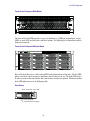
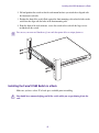
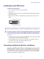
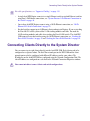
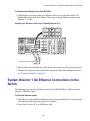
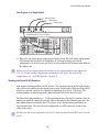
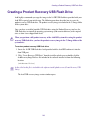
1
®
®
Avid ISIS 5500 | 5000
Setup Guide
Legal Notices
Product specifications are subject to change without notice and do not represent a commitment on the part of Avid Technology, Inc.
This product is subject to the terms and conditions of a software license agreement provided with the software. The product may
only be used in accordance with the license agreement.
This product may be protected by one or more U.S. and non-U.S patents. Details are available at www.avid.com/patents.
Part of the software embedded in this product is gSOAP software.
Portions created by gSOAP are Copyright (C) 2001-2004 Robert A. van Engelen, Genivia inc. All Rights Reserved.
THE SOFTWARE IN THIS PRODUCT WAS IN PART PROVIDED BY GENIVIA INC AND ANY EXPRESS OR IMPLIED
WARRANTIES, INCLUDING, BUT NOT LIMITED TO, THE IMPLIED WARRANTIES OF MERCHANTABILITY AND FITNESS FOR
A PARTICULAR PURPOSE ARE DISCLAIMED. IN NO EVENT SHALL THE AUTHOR BE LIABLE FOR ANY DIRECT, INDIRECT,
INCIDENTAL, SPECIAL, EXEMPLARY, OR CONSEQUENTIAL DAMAGES (INCLUDING, BUT NOT LIMITED TO,
PROCUREMENT OF SUBSTITUTE GOODS OR SERVICES; LOSS OF USE, DATA, OR PROFITS; OR BUSINESS
INTERRUPTION) HOWEVER CAUSED AND ON ANY THEORY OF LIABILITY, WHETHER IN CONTRACT, STRICT LIABILITY,
OR TORT (INCLUDING NEGLIGENCE OR OTHERWISE) ARISING IN ANY WAY OUT OF THE USE OF THIS SOFTWARE, EVEN
IF ADVISED OF THE POSSIBILITY OF SUCH DAMAGE.
This document is protected under copyright law. An authorized licensee of Avid ISIS 5500 may reproduce this publication for the
licensee’s own use in learning how to use the software. This document may not be reproduced or distributed, in whole or in part, for
commercial purposes, such as selling copies of this document or providing support or educational services to others. This document
is supplied as a guide for Avid ISIS 5500. Reasonable care has been taken in preparing the information it contains. However, this
document may contain omissions, technical inaccuracies, or typographical errors. Avid Technology, Inc. does not accept
responsibility of any kind for customers’ losses due to the use of this document. Product specifications are subject to change without
notice.
Copyright © 2010 Avid Technology, Inc. and its licensors. All rights reserved.
The following disclaimer is required by Sam Leffler and Silicon Graphics, Inc. for the use of their TIFF library:
Copyright © 1988–1997 Sam Leffler
Copyright © 1991–1997 Silicon Graphics, Inc.
Permission to use, copy, modify, distribute, and sell this software [i.e., the TIFF library] and its documentation for any purpose is
hereby granted without fee, provided that (i) the above copyright notices and this permission notice appear in all copies of the
software and related documentation, and (ii) the names of Sam Leffler and Silicon Graphics may not be used in any advertising or
publicity relating to the software without the specific, prior written permission of Sam Leffler and Silicon Graphics.
THE SOFTWARE IS PROVIDED “AS-IS” AND WITHOUT WARRANTY OF ANY KIND, EXPRESS, IMPLIED OR OTHERWISE,
INCLUDING WITHOUT LIMITATION, ANY WARRANTY OF MERCHANTABILITY OR FITNESS FOR A PARTICULAR PURPOSE.
IN NO EVENT SHALL SAM LEFFLER OR SILICON GRAPHICS BE LIABLE FOR ANY SPECIAL, INCIDENTAL, INDIRECT OR
CONSEQUENTIAL DAMAGES OF ANY KIND, OR ANY DAMAGES WHATSOEVER RESULTING FROM LOSS OF USE, DATA OR
PROFITS, WHETHER OR NOT ADVISED OF THE POSSIBILITY OF DAMAGE, AND ON ANY THEORY OF LIABILITY, ARISING
OUT OF OR IN CONNECTION WITH THE USE OR PERFORMANCE OF THIS SOFTWARE.
The following disclaimer is required by the Independent JPEG Group:
This software is based in part on the work of the Independent JPEG Group.
This Software may contain components licensed under the following conditions:
Copyright (c) 1989 The Regents of the University of California. All rights reserved.
Redistribution and use in source and binary forms are permitted provided that the above copyright notice and this paragraph are
duplicated in all such forms and that any documentation, advertising materials, and other materials related to such distribution and
use acknowledge that the software was developed by the University of California, Berkeley. The name of the University may not be
used to endorse or promote products derived from this software without specific prior written permission. THIS SOFTWARE IS
PROVIDED ``AS IS'' AND WITHOUT ANY EXPRESS OR IMPLIED WARRANTIES, INCLUDING, WITHOUT LIMITATION, THE
IMPLIED WARRANTIES OF MERCHANTABILITY AND FITNESS FOR A PARTICULAR PURPOSE.
Copyright (C) 1989, 1991 by Jef Poskanzer.
Permission to use, copy, modify, and distribute this software and its documentation for any purpose and without fee is hereby
granted, provided that the above copyright notice appear in all copies and that both that copyright notice and this permission notice
appear in supporting documentation. This software is provided "as is" without express or implied warranty.
Copyright 1995, Trinity College Computing Center. Written by David Chappell.
2
Permission to use, copy, modify, and distribute this software and its documentation for any purpose and without fee is hereby
granted, provided that the above copyright notice appear in all copies and that both that copyright notice and this permission notice
appear in supporting documentation. This software is provided "as is" without express or implied warranty.
Copyright 1996 Daniel Dardailler.
Permission to use, copy, modify, distribute, and sell this software for any purpose is hereby granted without fee, provided that the
above copyright notice appear in all copies and that both that copyright notice and this permission notice appear in supporting
documentation, and that the name of Daniel Dardailler not be used in advertising or publicity pertaining to distribution of the software
without specific, written prior permission. Daniel Dardailler makes no representations about the suitability of this software for any
purpose. It is provided "as is" without express or implied warranty.
Modifications Copyright 1999 Matt Koss, under the same license as above.
Copyright (c) 1991 by AT&T.
Permission to use, copy, modify, and distribute this software for any purpose without fee is hereby granted, provided that this entire
notice is included in all copies of any software which is or includes a copy or modification of this software and in all copies of the
supporting documentation for such software.
THIS SOFTWARE IS BEING PROVIDED "AS IS", WITHOUT ANY EXPRESS OR IMPLIED WARRANTY. IN PARTICULAR,
NEITHER THE AUTHOR NOR AT&T MAKES ANY REPRESENTATION OR WARRANTY OF ANY KIND CONCERNING THE
MERCHANTABILITY OF THIS SOFTWARE OR ITS FITNESS FOR ANY PARTICULAR PURPOSE.
This product includes software developed by the University of California, Berkeley and its contributors.
The following disclaimer is required by Paradigm Matrix:
Portions of this software licensed from Paradigm Matrix.
The following disclaimer is required by Ray Sauers Associates, Inc.:
“Install-It” is licensed from Ray Sauers Associates, Inc. End-User is prohibited from taking any action to derive a source code
equivalent of “Install-It,” including by reverse assembly or reverse compilation, Ray Sauers Associates, Inc. shall in no event be liable
for any damages resulting from reseller’s failure to perform reseller’s obligation; or any damages arising from use or operation of
reseller’s products or the software; or any other damages, including but not limited to, incidental, direct, indirect, special or
consequential Damages including lost profits, or damages resulting from loss of use or inability to use reseller’s products or the
software for any reason including copyright or patent infringement, or lost data, even if Ray Sauers Associates has been advised,
knew or should have known of the possibility of such damages.
The following disclaimer is required by Videomedia, Inc.:
“Videomedia, Inc. makes no warranties whatsoever, either express or implied, regarding this product, including warranties with
respect to its merchantability or its fitness for any particular purpose.”
“This software contains V-LAN ver. 3.0 Command Protocols which communicate with V-LAN ver. 3.0 products developed by
Videomedia, Inc. and V-LAN ver. 3.0 compatible products developed by third parties under license from Videomedia, Inc. Use of this
software will allow “frame accurate” editing control of applicable videotape recorder decks, videodisc recorders/players and the like.”
The following disclaimer is required by Altura Software, Inc. for the use of its Mac2Win software and Sample Source
Code:
©1993–1998 Altura Software, Inc.
The following disclaimer is required by Interplay Entertainment Corp.:
The “Interplay” name is used with the permission of Interplay Entertainment Corp., which bears no responsibility for Avid products.
This product includes portions of the Alloy Look & Feel software from Incors GmbH.
This product includes software developed by the Apache Software Foundation (http://www.apache.org/).
© DevelopMentor
This product may include the JCifs library, for which the following notice applies:
JCifs © Copyright 2004, The JCIFS Project, is licensed under LGPL (http://jcifs.samba.org/). See the LGPL.txt file in the Third Party
Software directory on the installation CD.
Avid Interplay contains components licensed from LavanTech. These components may only be used as part of and in connection
with Avid Interplay.
3
Attn. Government User(s). Restricted Rights Legend
U.S. GOVERNMENT RESTRICTED RIGHTS. This Software and its documentation are “commercial computer software” or
“commercial computer software documentation.” In the event that such Software or documentation is acquired by or on behalf of a
unit or agency of the U.S. Government, all rights with respect to this Software and documentation are subject to the terms of the
License Agreement, pursuant to FAR §12.212(a) and/or DFARS §227.7202-1(a), as applicable.
Trademarks
003, 192 Digital I/O, 192 I/O, 96 I/O, 96i I/O, Adrenaline, AirSpeed, ALEX, Alienbrain, AME, AniMatte, Archive, Archive II, Assistant
Station, AudioPages, AudioStation, AutoLoop, AutoSync, Avid, Avid Active, Avid Advanced Response, Avid DNA, Avid DNxcel, Avid
DNxHD, Avid DS Assist Station, Avid Ignite, Avid Liquid, Avid Media Engine, Avid Media Processor, Avid MEDIArray, Avid Mojo, Avid
Remote Response, Avid Unity, Avid Unity ISIS, Avid VideoRAID, AvidRAID, AvidShare, AVIDstripe, AVX, Beat Detective, Beauty
Without The Bandwidth, Beyond Reality, BF Essentials, Bomb Factory, Bruno, C|24, CaptureManager, ChromaCurve,
ChromaWheel, Cineractive Engine, Cineractive Player, Cineractive Viewer, Color Conductor, Command|24, Command|8,
Control|24, Cosmonaut Voice, CountDown, d2, d3, DAE, D-Command, D-Control, Deko, DekoCast, D-Fi, D-fx, Digi 002, Digi 003,
DigiBase, Digidesign, Digidesign Audio Engine, Digidesign Development Partners, Digidesign Intelligent Noise Reduction,
Digidesign TDM Bus, DigiLink, DigiMeter, DigiPanner, DigiProNet, DigiRack, DigiSerial, DigiSnake, DigiSystem, Digital
Choreography, Digital Nonlinear Accelerator, DigiTest, DigiTranslator, DigiWear, DINR, DNxchange, Do More, DPP-1, D-Show, DSP
Manager, DS-StorageCalc, DV Toolkit, DVD Complete, D-Verb, Eleven, EM, Euphonix, EUCON, EveryPhase, Expander,
ExpertRender, Fader Pack, Fairchild, FastBreak, Fast Track, Film Cutter, FilmScribe, Flexevent, FluidMotion, Frame Chase, FXDeko,
HD Core, HD Process, HDpack, Home-to-Hollywood, HYBRID, HyperSPACE, HyperSPACE HDCAM, iKnowledge, Image
Independence, Impact, Improv, iNEWS, iNEWS Assign, iNEWS ControlAir, InGame, Instantwrite, Instinct, Intelligent Content
Management, Intelligent Digital Actor Technology, IntelliRender, Intelli-Sat, Intelli-sat Broadcasting Recording Manager, InterFX,
Interplay, inTONE, Intraframe, iS Expander, iS9, iS18, iS23, iS36, ISIS, IsoSync, LaunchPad, LeaderPlus, LFX, Lightning, Link &
Sync, ListSync, LKT-200, Lo-Fi, MachineControl, Magic Mask, Make Anything Hollywood, make manage move | media, Marquee,
MassivePack, Massive Pack Pro, Maxim, Mbox, Media Composer, MediaFlow, MediaLog, MediaMix, Media Reader, Media
Recorder, MEDIArray, MediaServer, MediaShare, MetaFuze, MetaSync, MIDI I/O, Mix Rack, Moviestar, MultiShell, NaturalMatch,
NewsCutter, NewsView, NewsVision, Nitris, NL3D, NLP, NSDOS, NSWIN, OMF, OMF Interchange, OMM, OnDVD, Open Media
Framework, Open Media Management, Painterly Effects, Palladium, Personal Q, PET, Podcast Factory, PowerSwap, PRE,
ProControl, ProEncode, Profiler, Pro Tools, Pro Tools|HD, Pro Tools LE, Pro Tools M-Powered, Pro Transfer, QuickPunch,
QuietDrive, Realtime Motion Synthesis, Recti-Fi, Reel Tape Delay, Reel Tape Flanger, Reel Tape Saturation, Reprise, Res Rocket
Surfer, Reso, RetroLoop, Reverb One, ReVibe, Revolution, rS9, rS18, RTAS, Salesview, Sci-Fi, Scorch, ScriptSync,
SecureProductionEnvironment, Serv|GT, Serv|LT, Shape-to-Shape, ShuttleCase, Sibelius, SimulPlay, SimulRecord, Slightly Rude
Compressor, Smack!, Soft SampleCell, Soft-Clip Limiter, SoundReplacer, SPACE, SPACEShift, SpectraGraph, SpectraMatte,
SteadyGlide, Streamfactory, Streamgenie, StreamRAID, SubCap, Sundance, Sundance Digital, SurroundScope, Symphony, SYNC
HD, SYNC I/O, Synchronic, SynchroScope, Syntax, TDM FlexCable, TechFlix, Tel-Ray, Thunder, TimeLiner, Titansync, Titan, TL
Aggro, TL AutoPan, TL Drum Rehab, TL Everyphase, TL Fauxlder, TL In Tune, TL MasterMeter, TL Metro, TL Space, TL Utilities,
tools for storytellers, Transit, TransJammer, Trillium Lane Labs, TruTouch, UnityRAID, Vari-Fi, Video the Web Way, VideoRAID,
VideoSPACE, VTEM, Work-N-Play, Xdeck, X-Form, Xmon and XPAND! are either registered trademarks or trademarks of Avid
Technology, Inc. in the United States and/or other countries.
Apple, Macintosh, and Safari are either registered trademarks or trademarks of Apple Computer, Inc., registered in the U.S. and
other countries. HP is a registered trademark of Hewlett-Packard Company. Intel is a registered trademark of Intel Corporation. Java
is a trademark of Sun Microsystems in the United States and/or other countries. Kingston is a registered trademarks of Kingston
Technology Corporation. Small Tree is a registered trademark of Small Tree Communications, LLC used in the site are trademarks
or registered trademarks of Small Tree Communications, LLC. All other marks may be the property of their respective titleholders.
Windows is either a registered trademark or trademark of Microsoft Corporation in the United States and/or other countries. All other
trademarks contained herein are the property of their respective owners.
Avid ISIS 5500 | 5000 Setup Guide • 0175-31141-00 Rev. B • December 2013• Created 12/6/13
4
Contents
Using This Guide. . . . . . . . . . . . . . . . . . . . . . . . . . . . . . . . . . . . . . . . . . . . . . . 10
Symbols and Conventions . . . . . . . . . . . . . . . . . . . . . . . . . . . . . . . . . . . . . . . . . . . . . . . 10
If You Need Help. . . . . . . . . . . . . . . . . . . . . . . . . . . . . . . . . . . . . . . . . . . . . . . . . . . . . . . 11
Accessing the Online Documentation . . . . . . . . . . . . . . . . . . . . . . . . . . . . . . . . . . . . . . . 11
Avid Training Services . . . . . . . . . . . . . . . . . . . . . . . . . . . . . . . . . . . . . . . . . . . . . . . . . . 12
Chapter 1
Avid ISIS Overview . . . . . . . . . . . . . . . . . . . . . . . . . . . . . . . . . . . . . . . . . . . . . 13
Avid ISIS Hardware. . . . . . . . . . . . . . . . . . . . . . . . . . . . . . . . . . . . . . . . . . . . . . . . . . . . . 14
ISIS 5500 Engine Models. . . . . . . . . . . . . . . . . . . . . . . . . . . . . . . . . . . . . . . . . . . . . 14
Avid ISIS Front Panel . . . . . . . . . . . . . . . . . . . . . . . . . . . . . . . . . . . . . . . . . . . . . . . . 14
Data Drive LED Functions . . . . . . . . . . . . . . . . . . . . . . . . . . . . . . . . . . . . . . . . . 16
System Front Panel and LEDs . . . . . . . . . . . . . . . . . . . . . . . . . . . . . . . . . . . . . 16
Drive Array and Slot Locations . . . . . . . . . . . . . . . . . . . . . . . . . . . . . . . . . . . . . 18
Downloading and Installing the LSI MegaRAID Storage Manager Utility . . . . . 19
RAID Behavior in the Engine. . . . . . . . . . . . . . . . . . . . . . . . . . . . . . . . . . . . . . . 20
Avid ISIS Rear Panel . . . . . . . . . . . . . . . . . . . . . . . . . . . . . . . . . . . . . . . . . . . . . . . . 20
Expansion Slots. . . . . . . . . . . . . . . . . . . . . . . . . . . . . . . . . . . . . . . . . . . . . . . . . 20
System Drives . . . . . . . . . . . . . . . . . . . . . . . . . . . . . . . . . . . . . . . . . . . . . . . . . . 21
Power Supplies . . . . . . . . . . . . . . . . . . . . . . . . . . . . . . . . . . . . . . . . . . . . . . . . . 21
Activating the License Key . . . . . . . . . . . . . . . . . . . . . . . . . . . . . . . . . . . . . . . . 22
Avid ISIS Networks . . . . . . . . . . . . . . . . . . . . . . . . . . . . . . . . . . . . . . . . . . . . . . . . . . . . . 22
Direct Connect Clients . . . . . . . . . . . . . . . . . . . . . . . . . . . . . . . . . . . . . . . . . . . . . . . 22
System Director and Switch 1 Gb Connections . . . . . . . . . . . . . . . . . . . . . . . . . . . . 24
Engine and Switch 10 Gb Connections . . . . . . . . . . . . . . . . . . . . . . . . . . . . . . . . . . 24
Installation Consideration . . . . . . . . . . . . . . . . . . . . . . . . . . . . . . . . . . . . . . . . . . . . . . . . 25
Chapter 2
Optional Network Adapter Boards. . . . . . . . . . . . . . . . . . . . . . . . . . . . . . . . . 27
ISIS Engine Adapter Board Slots . . . . . . . . . . . . . . . . . . . . . . . . . . . . . . . . . . . . . . . . . . 27
Electrostatic Discharge Precautions . . . . . . . . . . . . . . . . . . . . . . . . . . . . . . . . . . . . . . . . 28
5
Removing and Installing the System Cover . . . . . . . . . . . . . . . . . . . . . . . . . . . . . . . . . . 28
Installing the Adapter Board . . . . . . . . . . . . . . . . . . . . . . . . . . . . . . . . . . . . . . . . . . . 30
Myricom 10-Gb Driver and Configuration Settings . . . . . . . . . . . . . . . . . . . . . . . . . . . . . 31
Intel Driver and Configuration Settings . . . . . . . . . . . . . . . . . . . . . . . . . . . . . . . . . . . . . . 31
Chapter 3
Installing the Avid ISIS System . . . . . . . . . . . . . . . . . . . . . . . . . . . . . . . . . . . 32
Avid ISIS Hardware. . . . . . . . . . . . . . . . . . . . . . . . . . . . . . . . . . . . . . . . . . . . . . . . . . . . . 32
Installing Avid ISIS Hardware in a Rack . . . . . . . . . . . . . . . . . . . . . . . . . . . . . . . . . . . . . 33
Rack-mount Requirements. . . . . . . . . . . . . . . . . . . . . . . . . . . . . . . . . . . . . . . . . . . . 33
Positioning the Avid ISIS Engine in the Rack. . . . . . . . . . . . . . . . . . . . . . . . . . . . . . 34
Separating the Slide Rails . . . . . . . . . . . . . . . . . . . . . . . . . . . . . . . . . . . . . . . . . . . . 35
Attaching Inner Slide Rails to the Avid ISIS 5500 . . . . . . . . . . . . . . . . . . . . . . . . . . 35
Attaching the Outer Rails to a Square-Hole Rack . . . . . . . . . . . . . . . . . . . . . . . . . . 36
Attaching the Outer Rails to a Round-Hole Rack . . . . . . . . . . . . . . . . . . . . . . . . . . . 38
Securing the Avid ISIS 5500 in a Rack . . . . . . . . . . . . . . . . . . . . . . . . . . . . . . . . . . 40
Installing the Force10 S25 and S4810 Switches in a Rack . . . . . . . . . . . . . . . . . . . 41
Installing the Force10 S60 Switch in a Rack . . . . . . . . . . . . . . . . . . . . . . . . . . . . . . 42
Installing the Avid ISIS Drives . . . . . . . . . . . . . . . . . . . . . . . . . . . . . . . . . . . . . . . . . . . . . 44
Connecting a Keyboard, Monitor, and Mouse. . . . . . . . . . . . . . . . . . . . . . . . . . . . . . . . . 44
Connecting Power Cords . . . . . . . . . . . . . . . . . . . . . . . . . . . . . . . . . . . . . . . . . . . . . . . . 46
Configuring Considerations. . . . . . . . . . . . . . . . . . . . . . . . . . . . . . . . . . . . . . . . . . . . . . . 46
Connecting Clients Directly to the System Director . . . . . . . . . . . . . . . . . . . . . . . . . . . . 47
System Director 1 Gb Ethernet Connections to the Switch . . . . . . . . . . . . . . . . . . . . . . 48
Force10 Ethernet Switches . . . . . . . . . . . . . . . . . . . . . . . . . . . . . . . . . . . . . . . . . . . . . . . 50
Force10 S25 Switch Modules . . . . . . . . . . . . . . . . . . . . . . . . . . . . . . . . . . . . . . . . . 51
10 Gb Ethernet S25 Switch Connections . . . . . . . . . . . . . . . . . . . . . . . . . . . . . 52
Stacking the Force10 S25 Switches . . . . . . . . . . . . . . . . . . . . . . . . . . . . . . . . . 55
Connecting Multiple Engines to the Stacked Switch . . . . . . . . . . . . . . . . . . . . . 56
Force10 S60 Switch Modules. . . . . . . . . . . . . . . . . . . . . . . . . . . . . . . . . . . . . . . . . . 58
10 Gb Ethernet S60 Switch Connections . . . . . . . . . . . . . . . . . . . . . . . . . . . . . 59
Stacking the Force10 S60 Switches . . . . . . . . . . . . . . . . . . . . . . . . . . . . . . . . . 62
Force10 S4810 Port Configuration. . . . . . . . . . . . . . . . . . . . . . . . . . . . . . . . . . . . . . 63
Connecting Multiple Engines to the Stacked Switch . . . . . . . . . . . . . . . . . . . . . . . . . . . . 63
Connecting to an In-House Network . . . . . . . . . . . . . . . . . . . . . . . . . . . . . . . . . . . . . . . . 66
6
Turning On the Avid ISIS 5500 Hardware. . . . . . . . . . . . . . . . . . . . . . . . . . . . . . . . . . . . 67
Chapter 4
Installing the Avid ISIS Software . . . . . . . . . . . . . . . . . . . . . . . . . . . . . . . . . . 68
Windows Operating System and Network Settings. . . . . . . . . . . . . . . . . . . . . . . . . . . . . 68
Setting the Date, Time, and Time Zone . . . . . . . . . . . . . . . . . . . . . . . . . . . . . . . . . . 68
Specifying a Unique Computer Name . . . . . . . . . . . . . . . . . . . . . . . . . . . . . . . . . . . 69
Virtual System Name . . . . . . . . . . . . . . . . . . . . . . . . . . . . . . . . . . . . . . . . . . . . . . . . 70
Software Installation . . . . . . . . . . . . . . . . . . . . . . . . . . . . . . . . . . . . . . . . . . . . . . . . . . . . 70
Connect the Network Cables to the Enclosure. . . . . . . . . . . . . . . . . . . . . . . . . . . . . 70
IP Addressing Strategies When Connecting to a Network . . . . . . . . . . . . . . . . . . . . 71
Loading the Software . . . . . . . . . . . . . . . . . . . . . . . . . . . . . . . . . . . . . . . . . . . . . . . . 71
Product Recovery Needs to be Copied to the USB Flash Drive . . . . . . . . . . . . . . . 83
Activating the License Key . . . . . . . . . . . . . . . . . . . . . . . . . . . . . . . . . . . . . . . . . . . . 83
Connecting the Optional Application Key . . . . . . . . . . . . . . . . . . . . . . . . . . . . . . . . . 84
Creating an Active File System . . . . . . . . . . . . . . . . . . . . . . . . . . . . . . . . . . . . . . . . 84
Checking or Changing the System Director IP Addresses. . . . . . . . . . . . . . . . . . . . 86
Accessing the Management Console From Any Computer . . . . . . . . . . . . . . . . . . . 88
Binding the Storage Managers. . . . . . . . . . . . . . . . . . . . . . . . . . . . . . . . . . . . . . . . . 89
Creating a Storage Group . . . . . . . . . . . . . . . . . . . . . . . . . . . . . . . . . . . . . . . . . . . . 90
Creating Workspaces . . . . . . . . . . . . . . . . . . . . . . . . . . . . . . . . . . . . . . . . . . . . . . . . 90
Creating User Accounts . . . . . . . . . . . . . . . . . . . . . . . . . . . . . . . . . . . . . . . . . . . . . . 91
Loading Client Software . . . . . . . . . . . . . . . . . . . . . . . . . . . . . . . . . . . . . . . . . . . . . . . . . 91
Configuring Client Software . . . . . . . . . . . . . . . . . . . . . . . . . . . . . . . . . . . . . . . . . . . . . . 94
Configuring the Client Network Properties . . . . . . . . . . . . . . . . . . . . . . . . . . . . . . . . . . . 96
Chapter 5
Avid ISIS Software Licensing. . . . . . . . . . . . . . . . . . . . . . . . . . . . . . . . . . . . . 97
What You Need to Activate the ISIS Software License. . . . . . . . . . . . . . . . . . . . . . . . . . 98
License Activation Using an Internet Connection . . . . . . . . . . . . . . . . . . . . . . . . . . . . . . 98
License Activation Without an Internet Connection. . . . . . . . . . . . . . . . . . . . . . . . . . . . 100
Deactivating the License . . . . . . . . . . . . . . . . . . . . . . . . . . . . . . . . . . . . . . . . . . . . . . . . 103
License Requirement with Host Name Change . . . . . . . . . . . . . . . . . . . . . . . . . . . . . . 103
Chapter 6
Configuring System Director Resiliency. . . . . . . . . . . . . . . . . . . . . . . . . . . 104
System Director Resiliency . . . . . . . . . . . . . . . . . . . . . . . . . . . . . . . . . . . . . . . . . . . . . . 104
Connecting Dual System Directors . . . . . . . . . . . . . . . . . . . . . . . . . . . . . . . . . . . . 106
Configuring a Second System Director . . . . . . . . . . . . . . . . . . . . . . . . . . . . . . . . . . . . . 107
7
Setting IP Addresses for Crossover Link . . . . . . . . . . . . . . . . . . . . . . . . . . . . . . . . 107
Configure the Resiliency Connection . . . . . . . . . . . . . . . . . . . . . . . . . . . . . . . . . . . 109
Stopping and Restarting the System Directors . . . . . . . . . . . . . . . . . . . . . . . . . . . . . . . 115
Binding Order for Health Monitoring . . . . . . . . . . . . . . . . . . . . . . . . . . . . . . . . . . . . . . . 117
Chapter 7
Avid ISIS Upgrade Guidelines . . . . . . . . . . . . . . . . . . . . . . . . . . . . . . . . . . . 119
Health Check. . . . . . . . . . . . . . . . . . . . . . . . . . . . . . . . . . . . . . . . . . . . . . . . . . . . . . . . . 119
Software Upgrade . . . . . . . . . . . . . . . . . . . . . . . . . . . . . . . . . . . . . . . . . . . . . . . . . . . . . 120
ISIS Client Software Installation . . . . . . . . . . . . . . . . . . . . . . . . . . . . . . . . . . . . . . . 122
Updating the 10 Gb Myricom Board Driver on Engines . . . . . . . . . . . . . . . . . . . . . 124
Post Upgrade System Verification . . . . . . . . . . . . . . . . . . . . . . . . . . . . . . . . . . . . . . . . 126
Preupgrade Information . . . . . . . . . . . . . . . . . . . . . . . . . . . . . . . . . . . . . . . . . . . . . . . . 128
Switch Information . . . . . . . . . . . . . . . . . . . . . . . . . . . . . . . . . . . . . . . . . . . . . . . . . 129
System Director Information. . . . . . . . . . . . . . . . . . . . . . . . . . . . . . . . . . . . . . . . . . 129
Optional Storage Information . . . . . . . . . . . . . . . . . . . . . . . . . . . . . . . . . . . . . . . . . 130
On Site Spares . . . . . . . . . . . . . . . . . . . . . . . . . . . . . . . . . . . . . . . . . . . . . . . . . . . . 131
Chapter 8
Adding and Replacing Hardware . . . . . . . . . . . . . . . . . . . . . . . . . . . . . . . . . 133
Removing and Replacing Data Drives . . . . . . . . . . . . . . . . . . . . . . . . . . . . . . . . . . . . . 133
Removing a Drive. . . . . . . . . . . . . . . . . . . . . . . . . . . . . . . . . . . . . . . . . . . . . . . . . . 133
Replacing a Drive . . . . . . . . . . . . . . . . . . . . . . . . . . . . . . . . . . . . . . . . . . . . . . . . . . 134
Replacing the ISIS Engine . . . . . . . . . . . . . . . . . . . . . . . . . . . . . . . . . . . . . . . . . . . . . . 135
Adding Optional Storage . . . . . . . . . . . . . . . . . . . . . . . . . . . . . . . . . . . . . . . . . . . . . . . . 138
Replacing System Drives in the Engine . . . . . . . . . . . . . . . . . . . . . . . . . . . . . . . . . . . . 140
Saving ISIS Metadata. . . . . . . . . . . . . . . . . . . . . . . . . . . . . . . . . . . . . . . . . . . . . . . 140
Replacing System Drives in the Engine . . . . . . . . . . . . . . . . . . . . . . . . . . . . . . . . . 141
Moving the Metadata to a New System Director . . . . . . . . . . . . . . . . . . . . . . . . . . 143
Switch Replacement . . . . . . . . . . . . . . . . . . . . . . . . . . . . . . . . . . . . . . . . . . . . . . . . . . . 144
Permanently Removing an ISIS Engine . . . . . . . . . . . . . . . . . . . . . . . . . . . . . . . . . . . . 146
Chapter 9
Product Recovery . . . . . . . . . . . . . . . . . . . . . . . . . . . . . . . . . . . . . . . . . . . . . 148
Creating a Product Recovery USB Flash Drive . . . . . . . . . . . . . . . . . . . . . . . . . . . . . . 149
Reinstalling the Windows Storage Server 2008 R2 Operating System . . . . . . . . . . . . 151
Configuring the System Drive Using Windows 2008 Storage Server Setup . . . . . . . . . 153
Chapter 10
Specifications and Notices. . . . . . . . . . . . . . . . . . . . . . . . . . . . . . . . . . . . . . 155
Dimensions and Weight . . . . . . . . . . . . . . . . . . . . . . . . . . . . . . . . . . . . . . . . . . . . . . . . 155
8
Environment . . . . . . . . . . . . . . . . . . . . . . . . . . . . . . . . . . . . . . . . . . . . . . . . . . . . . . . . . 155
Electrical . . . . . . . . . . . . . . . . . . . . . . . . . . . . . . . . . . . . . . . . . . . . . . . . . . . . . . . . . . . . 155
Uninterruptible Power Supply (UPS). . . . . . . . . . . . . . . . . . . . . . . . . . . . . . . . . . . . . . . 156
Supported Cabling . . . . . . . . . . . . . . . . . . . . . . . . . . . . . . . . . . . . . . . . . . . . . . . . . . . . 156
Appendix A
Safety and Regulatory Information . . . . . . . . . . . . . . . . . . . . . . . . . . . . . . . 160
Warnings and Cautions. . . . . . . . . . . . . . . . . . . . . . . . . . . . . . . . . . . . . . . . . . . . . . . . . 160
(Hebrew Warnings and Cautions)
. . . . . . . . . . . . . . . . . . . . . . . . . . . . . . . . . . . . . . . . . . . . . . . . . . . . . . . . . . . . . . . . . . 161
FCC Notice . . . . . . . . . . . . . . . . . . . . . . . . . . . . . . . . . . . . . . . . . . . . . . . . . . . . . . . . . . 161
Class A Equipment. . . . . . . . . . . . . . . . . . . . . . . . . . . . . . . . . . . . . . . . . . . . . . . . . 161
Modifications . . . . . . . . . . . . . . . . . . . . . . . . . . . . . . . . . . . . . . . . . . . . . . . . . . . . . 162
Cables . . . . . . . . . . . . . . . . . . . . . . . . . . . . . . . . . . . . . . . . . . . . . . . . . . . . . . . . . . 162
Canadian Notice (Avis Canadien) . . . . . . . . . . . . . . . . . . . . . . . . . . . . . . . . . . . . . . . . . 162
Class A Equipment. . . . . . . . . . . . . . . . . . . . . . . . . . . . . . . . . . . . . . . . . . . . . . . . . 162
LED Safety Notices . . . . . . . . . . . . . . . . . . . . . . . . . . . . . . . . . . . . . . . . . . . . . . . . . . . . 162
(Hebrew LED Safety Notices)
. . . . . . . . . . . . . . . . . . . . . . . . . . . . . . . . . . . . . . . . . . . . . . . . . . . . . . . . . . . . . . . . . . 163
European Union Declaration of Conformity. . . . . . . . . . . . . . . . . . . . . . . . . . . . . . . . . . 163
Disposal of Waste Equipment by Users in the European Union . . . . . . . . . . . . . . . . . . 165
Argentina Conformity . . . . . . . . . . . . . . . . . . . . . . . . . . . . . . . . . . . . . . . . . . . . . . . . . . 165
Australia and New Zealand EMC Regulations . . . . . . . . . . . . . . . . . . . . . . . . . . . . . . . 165
Japan EMC Regulations . . . . . . . . . . . . . . . . . . . . . . . . . . . . . . . . . . . . . . . . . . . . . . . . 166
Class A Equipment. . . . . . . . . . . . . . . . . . . . . . . . . . . . . . . . . . . . . . . . . . . . . . . . . 166
Korean EMC Regulations . . . . . . . . . . . . . . . . . . . . . . . . . . . . . . . . . . . . . . . . . . . . . . . 166
Class A Equipment. . . . . . . . . . . . . . . . . . . . . . . . . . . . . . . . . . . . . . . . . . . . . . . . . 166
Taiwan EMC Regulations . . . . . . . . . . . . . . . . . . . . . . . . . . . . . . . . . . . . . . . . . . . . . . . 166
Index . . . . . . . . . . . . . . . . . . . . . . . . . . . . . . . . . . . . . . . . . . . . . . . . . . . . . . . . 172
9
Using This Guide
The Avid® ISIS® 5500 real-time shared storage system is the foundation for reliable,
high-productivity media production. It is designed for media facilities and broadcasters using the
industry's most proven real-time storage software technology, delivering stable operation, high
performance media access, and class-leading value.
n
This document describes the features for all Avid ISIS shared storage networks. Therefore, your
system might not contain certain features that are covered in the documentation.
Symbols and Conventions
Avid documentation uses the following symbols and conventions:
Symbol or Convention Meaning or Action
n
A note provides important related information, reminders,
recommendations, and strong suggestions.
c
A caution means that a specific action you take could cause harm to
your computer or cause you to lose data.
w
>
A warning describes an action that could cause you physical harm.
Follow the guidelines in this document or on the unit itself when
handling electrical equipment.
This symbol indicates menu commands (and subcommands) in the
order you select them. For example, File > Import means to open the
File menu and then select the Import command.
This symbol indicates a single-step procedure. Multiple arrows in a list
indicate that you perform one of the actions listed.
(Windows), (Macintosh),
or (Linux)
This text indicates that the information applies only to the specified
operating system, either Windows Macintosh OS X or Linux.
Bold font
Bold font is primarily used in task instructions to identify user interface
items and keyboard sequences.
Italic font
Italic font is used to emphasize certain words and to indicate variables.
If You Need Help
Symbol or Convention Meaning or Action
Courier Bold font
Courier Bold font identifies text that you type.
Ctrl+key or mouse action
Press and hold the first key while you press the last key or perform the
mouse action. For example, Command+Option+C or Ctrl+drag.
If You Need Help
If you are having trouble using your Avid product:
1. Retry the action, carefully following the instructions given for that task in this guide. It is
especially important to check each step of your workflow.
2. Check the latest information that might have become available after the documentation was
published.
New information would be found in the ReadMe file supplied on your Avid installation
DVD as a PDF document and is also available online.
You should always check online for the most up-to-date release notes or ReadMe
because the online version is updated whenever new information becomes available. To
view the online versions, visit the Knowledge Base at www.avid.com/US/support.
3. Check the documentation that came with your Avid application or your hardware for
maintenance or hardware-related issues.
4. Visit the online Knowledge Base at www.avid.com/US/support. Online services are
available 24 hours per day, 7 days per week. Search this online Knowledge Base to find
answers, to view error messages, to access troubleshooting tips, to download updates, and to
read or join online message-board discussions.
Accessing the Online Documentation
The Avid ISIS online documentation contains all the product documentation in PDF format. You
can access the documentation in the AvidISISDocumentation folder on the Avid ISIS installer
kit. You need to download and install Acrobat Reader on your Avid ISIS 5500 before you can
access the PDF documentation.
n
You need to download and install Acrobat Reader on your Avid ISIS 5500 before you can access
the PDF documentation.
11
Avid Training Services
To access the online documentation from the installer kit:
1. Insert your Avid ISIS USB flash drive with the Avid ISIS software kit into the USB port.
2. Navigate to the [USB flash drive]:\.AvidISISDocumentation folder, and double-click the
PDF file for the document you want to view.
Avid Training Services
Avid makes lifelong learning, career advancement, and personal development easy and
convenient. Avid understands that the knowledge you need to differentiate yourself is always
changing, and Avid continually updates course content and offers new training delivery methods
that accommodate your pressured and competitive work environment.
For information on courses/schedules, training centers, certifications, courseware, and books,
please visit www.avid.com/support and follow the Training links, or call Avid Sales at
800-949-AVID (800-949-2843).
12
1 Avid ISIS Overview
The document describes features and hardware of the Avid ISIS 5500. Depending on your
configuration, your Avid ISIS system might not contain certain features and hardware that are
covered in the document. Information that applies to specific models is specified in that section.
The term “Avid ISIS” is used when the information applies to all models.
Avid ISIS uses industry standard components to deliver high capacity, high performance
collaborative media solutions. A single Avid ISIS chassis provides System Director and Engine
(Storage Server) functionality. Each Avid ISIS Engine is comprised of 16 media storage drives,
two mirrored system drives, RAID controller, Gigabit and 10 Gigabit Ethernet plus redundant
power and fans. Up to six Engines are supported in the ISIS 5500, with 2 TB media storage
drives can be combined to deliver 192 TB of shared storage and with 4TB drives can deliver 384
TB of shared storage. The first ISIS Engine provides System Director and Management Console
functionality in addition to media storage. The Avid ISIS 5500 network can support up to 90
Ethernet connected clients.
Avid ISIS assures media protection and availability using the following techniques:
•
Mirrored system drives are used for system operation and System Director metadata storage.
•
A failed system drive can be replaced without interrupting the operation of the Avid ISIS.
•
The 16 data drives are configured into three RAID 5 groups with one drive reserved as a
global hot spare. If any of the RAID drives fail, the Avid ISIS automatically uses the spare
drive to rebuild the RAID group. The failed drive can be removed and replaced with a new
drive without interrupting the operation of the Avid ISIS.
Topics in this chapter include:
•
Avid ISIS Hardware
•
Avid ISIS Networks
•
Installation Consideration
Avid ISIS Hardware
Avid ISIS Hardware
The Avid ISIS Engine uses the Windows® Storage Server 2008 R2 operating system with
Service Pack 2. The Avid ISIS client operating systems that are supported in your ISIS software
release is listed in the Avid ISIS ReadMe. The ISIS Engine contains sixteen drives for storing
data. The size of the data drives is shown on the front of each drive. As newer technology is
released, other drive capacities might be supported.
n
The Windows Product Key Certificate of Authenticity is attached to the top cover of the Avid ISIS
enclosure.
The Avid ISIS 5500 Engine can be configured as a standalone system that runs the Avid ISIS
5500 System Director software. Up to six Engines can be grouped to create a larger shared
storage environment. One of the Engines must have the System Director software. ISIS Engines
are available in the following models.
ISIS 5500 Engine Models
Major differences between the Engines are listed below. Also review the information listed
“Installation Consideration” on page 25.
•
•
•
ISIS 5500-64
-
4 TB drives
-
Includes the Myricom 10 Gb Ethernet adapter board
-
(Optional) Quad Port 1 Gb Ethernet adapter board
ISIS 5500-32
-
2 TB drives
-
Includes the Myricom 10 Gb Ethernet adapter board
-
(Optional) Quad Port 1 Gb Ethernet adapter board
ISIS 5500-16
-
1 TB drives
-
Includes Myricom 10 Gb Ethernet adapter board
-
(Optional) Quad Port 1 Gb Ethernet adapter board
Avid ISIS Front Panel
The Avid ISIS 5500 comes with an Avid bezel that covers the front of the enclosure and can be
locked to prevent unauthorized personnel from accessing the buttons and data drives. The
following is an illustration of the Avid ISIS enclosure with the front bezel installed.
14
Avid ISIS Hardware
Front of the Enclosure With Bezel
The front of the Avid ISIS provides access to 16 data drives, a USB port, network port activity
LEDs, an error LED, and the Power and Reset buttons. The following is an illustration with the
front bezel removed.
Front of the Enclosure Without Bezel
ID
Each of the data drives have a blue and red LED on the bottom front of the drive. The left LED
(blue) is on when a drive has power and flashes when the drive is in use. The right LED (red) is
lit when an error is detected with the drive and the drive needs to be replaced. Details on the data
drive LED indicators are in the following table.
Data Drives
Drive carrier latch Drive lock
Fault LED (red)
Power/Activity LED (blue)
15
Avid ISIS Hardware
Data Drive LED Functions
6 Gb SAS Expander — Data Drive LED Functions
Drive State
Blue LED
Red LED
Management Console
Messaging
Comments
Online Inactive
On solid
Off
No Special Status
Healthy online drive,
no disk I/O
On-line Active
Activity
Off
No Special Status
Healthy online drive,
with disk I/O
Healthy Spare
On solid
Off
No Special Status
Healthy Global Hot Spare disk
Online Disk in a
Degraded Set
On solid/
Activity
Fast flashing
Error – Disk Performance
Degraded
Nothing needs to be done to
these online drives, but failed
drive should be replaced
Spare Rebuilding
Activity
Slow flashing
Error – Disk Performance Rebuild automatically occurs
Degraded – Rebuilding x% on drive failure by using Hot
Spare disk
Data Rebuilding
Activity
Fast flashing
Error – Disk Performance Rebuild automatically occurs
Degraded – Rebuilding x% on drive failure by using Hot
Spare disk
Consistency Check Activity
Off
Checking Raid Set – x%
No user intervention required
Initializing
Activity
Off
Initializing Raid Set – x%
Happens on initial array
creation
Failed Data Disk
On solid
On solid
Error – Disk Performance
Degraded
Should replace disk
Failed Spare Disk
On solid
On solid
Missing Spare
Should replace disk
Unused Disk
On solid
Off
No Special Status
No user intervention required
Non-Branded
On solid
Slow flashing
Warning – Unapproved
Should replace disk
spare disk attempting to be
added as a hot spare
System Front Panel and LEDs
The system has 8 LEDs on the top of the front panel organized into two rows, each row with four
LEDs. The first 3 columns of LEDs (6 LEDs) represent activity on each of the six network ports.
The top right LED represents system hardware errors. The bottom right LED represents system
drive activity. The following figure shows the front view and system control panel.
16
Avid ISIS Hardware
System Director Front View
A
B
C
D
E F
G
H
ID
Control panel
The following table describes the control panel shown in the previous figure.
System Control Panel
Letter
Description
Description
A
Universal serial bus (USB) port
USB 2.0 device port on the front of the system
supports one USB device. Recommended for use
when re-imaging the system drives or loading
software. Two more USB ports are located on the
back of the system.
B
Halt or Non-maskable interrupt (NMI) The halt or NMI signal halts the processor, which
button
effectively halts the server. A NMI is the highest
priority interrupt and cannot be masked by software.
the Halt/NMI button is pressed, the NMI
c Ifsignal
locks the system and the system must
be restarted to clear the interrupt.
C
System reset button
Preforms a soft reset when pressed. Do not use this
button unless the system has had a fatal error and you
need to restart. A soft reset restarts the system; it
clears all active program memory (you lose unsaved
work) and shuts down all active programs.
D
Six green network activity LEDs
Illuminates green when a good network connection is
established and blinks when there is network activity
on the six built-in 1-Gb network ports. The number
beside the LED corresponds with the number beside
the network port on the rear of the enclosure.
E
Red System error LED
Illuminates red when an error is detected with the
system (fan, power supply, temperature, voltage).
17
Avid ISIS Hardware
System Control Panel (Continued)
Letter
Description
Description
F
System Drive activity LED
Indicates drive activity from the onboard SATA
controller and blinks when either of the system drives
is being accessed.
G
System ID button
When pressed it illuminates blue and also illuminates
an LED on the rear of the enclosure. The rear LED is
also blue and is on the lower left-hand side of the
Ethernet ports. It is used to identify a system for
servicing when it is installed in a high-density
rack/cabinet populated with several other similar
systems.
H
Power button
Press to power on the enclosure. Power button
illuminates green when the power is on.
Drive Array and Slot Locations
For data integrity, three RAID 5 groups are created in the each Avid ISIS storage enclosure
(Engine) using the 16 data drives with one drive reserved as a global hot spare. The global hot
spare allows a degraded raid set to be quickly repaired if a drive fails. This results in continued
access to your workspace data with no data loss during the failure and repair.
Each Engine provides 16 TB in the ISIS 5500-16 and 32 TB in the ISIS 5500-32 and 64 TB in
the ISIS 5500-64 of storage with the option to bind up to six Engines for a possible total of
384 TB. New installations are created using a common slot configuration. However, once a disk
has failed, the initial layout changes and the default configuration no longer applies. The
numbers assigned to the slots and the group numbers are not displayed in the ISIS software.
These numbers and groups are only displayed in the LSI MegaRAID Storage Manager.
n
c
The LSI MegaRAID Storage Manager is a RAID utility that you might be asked to use when
instructed to by Avid Customer Support. This utility is not automatically installed with your ISIS
software installation. You must access the LSI Corporation site to download under LSI's terms
and conditions. See “Downloading and Installing the LSI MegaRAID Storage Manager Utility”
on page 19 for instructions on downloading the LSI MegaRAID Storage Manager Utility.
The following drive configuration is created when the RAID groups are initially
configured. Once a drive group has used the spare drive and a new spare is established, the
following information no longer applies. The following RAID group configuration changed
from the initial release. These changes have been incorporated into Engine shipments
starting in September 2011.
18
Avid ISIS Hardware
6 Gb SAS Expander — Initial Data Drive Slot Locations and RAID Groups
Slot 1 – RAID Group 0
Slot 5 – RAID Group 0
Slot 9 – RAID Group 1
Slot 13 – RAID Group 2
Slot 2 – RAID Group 0
Slot 6 – RAID Group 1
Slot 10 – RAID Group 1 Slot 14 – RAID Group 2
Slot 3 – RAID Group 0
Slot 7 – RAID Group 1
Slot 11 – RAID Group 2 Slot 15 – RAID Group 2
Slot 4 – RAID Group 0
Slot 8 – RAID Group 1
Slot 12 – RAID Group 2 Slot 16 – Spare
Downloading and Installing the LSI MegaRAID Storage Manager Utility
Access the LSI website to download the utility.
To download the utility:
1. Go to www.lsi.com
2. Click Support >Find Help > Find Support Documents & Downloads by Product.
3. In the Search by keyword box enter 9260-4i (This is the model of the Raid Controller
installed in the ISIS 5500 chassis.)
4. Expand Management Software and Tools.
5. Choose the Latest MegaRaid Storage Manager.
6. Accept the License Agreement.
7. Download the file to the local system.
To install the utility:
1. Extract the downloaded zip file.
2. Run the Setup.exe.
3. Accept the license agreement.
4. Accept the Customer Info default and click Next.
5. Accept the Destination folder default and click Next.
6. In the Setup Type window select Complete and click Next.
7. In the LDAP Logon Information window, choose No and click Next.
8. Click Finish.
The utility will be installed on your system. You can launch the utility from Start >
Programs > MegaRAID Storage Manager.
19
Avid ISIS Hardware
RAID Behavior in the Engine
Once the three RAID groups have been created, any of the drives in the Engine can be swapped
within the Engine. The Avid ISIS uses the drive IDs to track what five drives are members of
each of the three RAID groups.
If a single drive should fail, the Avid ISIS automatically starts a repair of the RAID group using
the spare drive in the Engine.
Avid ISIS Rear Panel
The Avid ISIS rear panel provides access to the power supplies, system drives, video port,
1 gigabit (Gb) Ethernet connectors, 10 Gb Ethernet port, serial connector, and two USB
connectors for the application key, and keyboard or mouse.
n
The following illustration shows the shipping configuration of the ISIS 5500-32. The Quad Port 1
Gb Ethernet adapter board (not shown) is optional in the ISIS 5500-16, ISIS 5500-32 and ISIS
5500-64. For instructions on installing the optional adapters boards, see “Optional Network
Adapter Boards” on page 27.
Avid ISIS 5500-32 Rear Panel
System drives
Top power
connector
Bottom power
connector
Intel Pro 1 Gb
Ethernet ports
ID LED
(lit with ID button
on front is pressed)
Video port
LSI MegaRAID
Serial port
controller
USB ports
Myricom 10 Gb
Ethernet port
Expansion Slots
There are six expansion slots accessible from the rear of the Avid ISIS enclosure. The following
tables lists the standard boards that are supported in the Avid ISIS and storage expansion slots.
20
Avid ISIS Hardware
Supported Slot Configuration
PCI Slot
Interface
Description
2 PCI-E x16
10 Gb Ethernet
Myricom® board
The 10 Gb Ethernet Myricom board is installed in the
second PCI-E x16 connector on the ISIS 5500 Engine.
This is a 10-Gb connection for configurations with
multiple storage enclosures or for a single 10-Gb client
in a direct connect configuration.
3 PCI-E x8
Internal LSI® RAID
controller board
The LSI MegaRAID board is installed in the third PCI-E
x8 connector. There is no external connection. The LSI
board connects to an internal SAS Expander board using
a SAS cable.
4 PCI-E x8
Intel® 4-Port Ethernet
board
The Intel 4-port Ethernet board is installed in the forth
PCI-E x8 connector. This is an option board for direct
connect configuration, adding four more 1 Gb direct
connect clients.
1, 5, and 6
None
These slots are not used. No optional adapter boards are
supported.
System Drives
There are two system drives accessible from the rear of the Avid ISIS enclosure. These two
drives are mirrored and if a failure occurs on either one of the system drives, you can pull the
failed drive out of the enclosure and install a replacement drive without turning off the Avid ISIS
enclosure. As soon as a replacement system drive is installed, the working system drive creates a
mirror of the original drive on the new drive. All Avid ISIS operations continue to run
uninterrupted.
n
The drive carriers for the system drives are locked to prevent them from opening during
shipment. The plastic drive carrier key is mounted on the rear of the enclosure beside the system
drives.
Power Supplies
There are two power supplies accessible from the rear of the Avid ISIS enclosure. If a failure
occurs on either one of the power supplies, you can pull the failed power supply out of the
enclosure and install a replacement power supply without turning off the Avid ISIS enclosure.
All Avid ISIS operations continue to run uninterrupted.
21
Avid ISIS Networks
Activating the License Key
You need to activate your Avid ISIS software before you can make an Active File System. After
installing your software, see “Avid ISIS Software Licensing” on page 97
n
Previous versions of Avid ISIS software use an application key plugged into the System Director
to allow clients to connected to the ISIS infrastructure. The USB application key is now available
as an option. New ISIS systems ship with software licensing that is activated online. If you are
already using an application key (dongle) in your ISIS infrastructure you can continue using it.
Software licensing is only required with new ISIS installations. Clients cannot access the Avid
ISIS software until the license key has been activated.
If configuring a Dual System Director for metadata redundancy, you need a second software
license or application key for the second System Director, For more information, see
“Configuring System Director Resiliency” on page 104.
Avid ISIS Networks
The Avid workgroup uses an Avid ISIS to provide clients access to Avid ISIS workspaces
(shared folders) over a 1 Gb Ethernet network (see “Avid ISIS Infrastructure — Clients with One
or Two Switches” on page 24 and “Avid ISIS Infrastructure — with Optional Storage” on
page 25). You can have several workgroups at your site, each accommodating multiple Ethernet
clients.
Workspaces can be mounted on Ethernet clients, and then accessed in the same manner as local
drives. The Avid ISIS allows clients to mount up to 21 workspaces. Clients can then play,
capture, and edit media on the workspaces using networking protocol optimized by Avid for
real-time media transfer. Real-time media reads and writes are not possible unless the connected
clients are running a qualified Avid editing application and have the Avid ISIS client software
installed. See the Avid ISIS ReadMe for a list of supported hardware and Avid editing
applications.
n
When workspaces are mapped to drive letters, depending on the number of drives in the client
system, the maximum number of workspaces that can mounted is 21. You can mount more
workspaces with UNC mounting.
Direct Connect Clients
The Avid ISIS 5500 direct connect configuration provides access to shared workspaces by
connecting up to nine clients directly into a single Avid ISIS Engine. The following illustrations
shows the Avid ISIS Engine rear panel with optional Quad Port 1 Gb Ethernet adapter board
installed and the Myricom 10 Gb Ethernet board (shipped installed in the ISIS 5500 Engines.)
22
Avid ISIS Networks
Depending if you have installed the optional Quad Port 1 Gb Ethernet adapter board, four or
eight direct connect 1 Gb clients are available. The Myricom 10 Gb Ethernet board offers one
10 Gb direct connect client.
n
You cannot mix an Ethernet switch configuration and clients that are directly connected.
Direct connect options include:
n
•
The ISIS 5500-64, ISIS 5500-32 and ISIS 5500-16 Engines both support up to eight 1 Gb
clients directly connected to the built-in Intel Pro 1000 Ethernet ports and when using the
optional Quad Port 1 Gb Ethernet adapter board. The built-in Intel Pro 1000 ports are the
four outside ports (labeled 1, 3, 4, and 6). The Quad Port Ethernet boards are not labeled but
are ports 8 to 11 from top to bottom.
•
The Quad Port 1 Gb Ethernet adapter board does not ship installed in the ISIS 5500-64, ISIS
5500-32 or the ISIS 5500-16 Engines. This optional board is only supported in single Engine
direct connect configurations when you want 5 to 8, 1 Gb clients connected to the ISIS
Engine.
The Quad Port 1 GB Ethernet adapter board is option in the ISIS 5500 Engines. For instructions
on installing the Ethernet adapter board, see “Optional Network Adapter Boards” on page 27.
•
n
The Myricom 10 Gb Ethernet board is shipped installed in the ISIS 5500-64, ISIS 5500-32
and the 5500-16 Engine. This board is the 10 Gb connection for configurations with multiple
storage enclosures or for a single 10 Gb client in a direct connect configuration.
Avid ISIS 5500 direct connect configurations do not support dual-link client connections or Avid
Interplay environments.
Avid ISIS Infrastructure — Direct Connect Clients
ISIS 5500
1 Gb Ethernet
Ethernet client
Ethernet client
Ethernet client
3
6
1
4
Ethernet client
Up to 4 clients
1 Gb Ethernet
Ethernet client
Ethernet client
Ethernet client
Ethernet client
10 Gb Ethernet
10 Gb Ethernet client
Up to 4 clients
23
Avid ISIS Networks
System Director and Switch 1 Gb Connections
A single ISIS Engine can connect to a switch using the four Intel Pro 1000 1 Gb Ethernet ports
(1, 3, 4, and 6) on the rear of the Engine. When using a single Engine, that Engine must be
configured as the System Director. Clients access workspaces on the System Director through
the Ethernet switch. If any of the four Ethernet port connections to the switch fails, the Avid ISIS
continues to operate. Clients can continue to access workspaces through the switch even when
only one Ethernet port is connected to the System Director. This is not an approved
configuration, but a safeguard if the other Ethernet connections are lost. If you stack the two
switches, you can connect up to 90, 1-Gb Ethernet clients, For instructions on setting up this
configuration, see “System Director 1 Gb Ethernet Connections to the Switch” on page 48.
Avid ISIS Infrastructure — Clients with One or Two Switches
ISIS 5500
1
4
3
6
Ethernet switch
Ethernet client
Ethernet client
Ethernet client
Ethernet client
1 Gb Ethernet
Up to 90 clients
Engine and Switch 10 Gb Connections
A 10 Gb connection between your Engine and switch allows you setup the switch and clients a
greater distance away from the Avid ISIS system. You can use the 10 Gb port in the Engine for a
single or multiple Engine configuration. When using multiple Engines, you are required to use
the 10 Gb connection in the System Director and Engines to the switch. When using a single
Engine, that Engine must be configured as the System Director and can use either the 1 Gb ports
or 10 Gb port to connect to the switch.The stacked switch configuration allows you to connect up
to 90 1-Gb Ethernet clients (see “10 Gb Ethernet S25 Switch Connections” on page 52 and “10
Gb Ethernet S60 Switch Connections” on page 59).
24
Installation Consideration
Avid ISIS Infrastructure — with Optional Storage
ISIS 5500
Optional storage enclosures
Avid ISIS
Avid ISIS
Avid ISIS
Avid ISIS
Avid ISIS
Ethernet switch
Ethernet client
Ethernet client
Ethernet client
10 Gb Ethernet
Ethernet client
Up to 90 clients
Installation Consideration
To set up an Avid ISIS environment you need:
n
•
An Avid ISIS Engine
•
Avid ISIS software
If using System Director Resiliency, the software license or an Application Key must be installed
on both the Active and Standby System Directors.
•
Several Avid ISIS Ethernet client connection options are listed as follows. See the Avid ISIS
ReadMe for the latest list of qualified Ethernet switches
-
Up to five clients (including the 10GB client) can connect directly into the Intel Pro
network ports (1, 3, 4, and 6) on the rear of the System Director (see “Direct Connect
Clients” on page 22).
-
Up to nine clients can connect directly to a single Engine configuration when using the
built-in Intel Pro network ports and when the optional Quad Port 1 Gb Ethernet adapter
is installed (ports 8, 9, 10, and 11).
-
Up to 20, 1-Gb Ethernet clients are supported on the Force10 S25 Ethernet switch using
four 1-Gb connections to the System Director. This is nonblocking gigabit Ethernet
switch (see “System Director and Switch 1 Gb Connections” on page 24).
25
Installation Consideration
-
Up to 24, 1-Gb Ethernet clients are supported on the Force10 S25 Ethernet switch using
a 10-Gb connection to the System Director (see “Engine and Switch 10 Gb
Connections” on page 24).
-
Up to 44, 1-Gb Ethernet clients are supported on the Force10 S60 Ethernet switch using
four 1-Gb connections to the System Director.
-
Up to 47, 1-Gb Ethernet clients are supported on the Force10 S4810 Ethernet switch
using a 10-Gb connection to the System Director.
-
Up to 48, 1-Gb Ethernet clients are supported on the Force10 S60 Ethernet switch using
a 10-Gb connection to the System Director.
-
Up to 44, 1-Gb Ethernet clients are supported across two stacked Force10 S25 Ethernet
switches using four 1-Gb connections to the System Director. (20 clients in the first
Force10 S25 switch, 24 on the second). These switches are stacked using a 12 Gb
stacking connection.
-
Up to 48, 1-Gb Ethernet clients are supported across two stacked Force10 S25 Ethernet
switches using a 10-Gb connection to the System Director. (24 clients in the first
Force10 S24 switch, 24 on the second, two ports unused). These two switches are
stacked using a 12 Gb stacking connection.
-
Up to 90, 1-Gb Ethernet clients are supported with the Force10 S4810, Cisco® 4900, and
Cisco 4948 Ethernet switches.
The Avid ISIS supports additional storage enclosures. When expanding with an Avid ISIS
storage you must take the following into consideration:
•
The spare drive in each enclosure can only repair failures that occur in that same enclosure.
You cannot repair a bad drive in the Avid ISIS System Director enclosure with the spare
drive that is located in a second Avid ISIS enclosure. The spare drive in the second enclosure
can be moved to an open slot in the first enclosure and made into a spare for the new
enclosure.
•
You cannot mix ISIS 5500-64 (4TB), ISIS 5500-32 (2 TB) drives or ISIS 5500-16 (1 TB)
drives in the same ISIS 5500 Engine.
•
Once a disk has been added to the data set it must not be moved between Avid ISIS
enclosures. Doing so corrupts the data on that disk.
26
2 Optional Network Adapter Boards
This chapter provides procedures for adding and replacing network adapter boards in your Avid
ISIS 5500. Do not add any hardware if there are any issues with the system. Correct all problems
before adding new hardware and making changes to the system. Perform a quick check to verify
that the system is in good working order.
Topics in this chapter include:
•
ISIS Engine Adapter Board Slots
•
Electrostatic Discharge Precautions
•
Removing and Installing the System Cover
•
Myricom 10-Gb Driver and Configuration Settings
•
Intel Driver and Configuration Settings
For information that describes specific models, “ISIS 5500 Engine Models” on page 14.
n
A #2 Phillips-head screwdriver is needed to perform the procedures described in this section,
ISIS Engine Adapter Board Slots
The following illustrations shows the Avid ISIS Engine rear panel with the Ethernet adapter
boards installed. The 10 Gb Myricom board is shipped in the ISIS 5500-64, ISIS 5500-32 and
the ISIS 50500-16 Engine
The ISIS 5500-16 Engine does not include the Quad Port 1 Gb Ethernet adapter boards.
•
The Myricom® 10 Gb Ethernet board is shipped installed in the ISIS 5500-64, ISIS 5500-32
and the ISIS 5500-16 Engine. This board is the 10 Gb connection for configurations with
multiple storage enclosures or for a single 10 Gb client in a direct connect configuration.
•
The LSI MegaRAID controller board is shipped installed in the ISIS 5500-64, ISIS 5500-32
and ISIS 50500-16 Engines. There is no external connection. This board is the internal SAS
RAID controllers.
•
The Intel four port 1 Gb Ethernet board does not ship installed in any of the ISIS 5500-64,
ISIS 5500-32 or the ISIS 5500-16 Engines. This optional board is only in direct connect
configurations when you want 5 to 8 1 Gb clients connected to the ISIS Engine. For sample
Electrostatic Discharge Precautions
configurations see “Direct Connect Clients” on page 22.
Avid ISIS Rear Panel
Quad port
Myricom 10 Gb
1 Gb Ethernet
Ethernet port
LSI MegaRAID
controller
Electrostatic Discharge Precautions
Electrostatic discharge (ESD) can damage disk drives, electronic components, and other parts.
Avid recommends that you perform all procedures in this chapter only at an ESD workstation. If
one is not available, provide some ESD protection by wearing an antistatic wrist strap attached to
chassis ground (any unpainted metal surface) on your Engine when handling parts.
Always handle boards carefully. They can be extremely sensitive to ESD. Hold electronic boards
only by their edges. After removing a board from its protective wrapper, place the board
component side up on a grounded, static free surface. Use a conductive foam pad if available but
not the wrapper. Do not slide the board over any surface.
Removing and Installing the System Cover
To remove the top cover:
1. Observe the safety precautions described in “Electrostatic Discharge Precautions” on
page 28.
2. Make sure the Engine is powered off and all peripheral devices and AC power cords are
disconnected.
3. Remove the four top cover screws shown in the following illustration.
4. Completely loosen the captive thumb screws on the back of the Engine.
5. Pull the two pull tabs on the sides of the cover outward and lift the cover off the system.
28
Removing and Installing the System Cover
Removing the Top System Cover
Front
Pull tabs
Top cover
screws
Thumb screws
To install the server system cover:
1. Place the cover over the Engine so that the side edges of the cover sit just outside the Engine
sidewalls.
2. While pulling the tabs outward, slide the cover forward until the tabs click into place and
release the pull tabs.
3. Replace the four top cover screws previously removed.
4. Tighten the rear thumbscrews.
5. Reconnect all peripheral devices and the AC power cords.
29
Removing and Installing the System Cover
Installing the Adapter Board
To install the adapter board:
1. Observe the safety precautions described in “Electrostatic Discharge Precautions” on
page 28.
2. Remove the Engine as previously described, see “Removing and Installing the System
Cover” on page 28.
3. Identify the appropriate slot for the adapter boards you are installing.
4. Remove the screw securing the blank panel associated with the slot where you are installing
the adapter board.
Removing the Blank Panel
Front
Myricom 10 Gb
Ethernet port
LSI MegaRAID
controller
Quad port
1 Gb Ethernet
Blank covers
and screw
30
Myricom 10-Gb Driver and Configuration Settings
5. Insert the adapter board so that it fits into the connector and fills the hole where you
previously removed the blank panel. Be sure to seat the tab at the bottom panel seats into the
slot on the bottom of the Engine chassis.
n
Make sure that any empty adapter board slots have blank panels installed.
6. Replace the top cover, see “Removing and Installing the System Cover” on page 28.
7. Reconnect all peripheral devices and the AC power cords into the Engine.
Myricom 10-Gb Driver and Configuration Settings
The preloaded Avid software includes a Myricom driver. The Myricom driver is installed and the
settings are configured for you when you install the Avid ISIS software on the System Director
and Engines.
Intel Driver and Configuration Settings
After you install the Quad Port 1 Gb network adapter board and restart your system, you might
receive a Hardware Wizard message about needing a driver for the Quad Port Ethernet adapter
board. Cancel the message. The driver is installed and the settings are configured for you when
you install the Avid ISIS software on the System Director and Engines. The following settings
are provided for reference. A copy of the Intel driver can be found in the Avid ISIS software kit:
\Drivers\ISIS 5000\Intel_Pro1000\Intel_17.4_Win2K8-8-7-Vista_64
n
If you have made a change to the Intel settings and want to set them back to the Avid defaults,
re-run the ISIS software installer (autorun.exe) and the Avid network settings are re-applied. If
the network setting are not set to the Avid defaults, a message is displayed in the ISIS
Management Console.
Quad Port 1 Gb Network Settings On The Engine
Option
Setting
Flow Control
Enabled
Interrupt Moderation
Disabled
Interrupt Throttling Rate
Disabled
Receive Buffers
1024
Transmit Buffers
1024
31
3 Installing the Avid ISIS System
This chapter describes how to install an Avid ISIS and the Ethernet switches to create a
workgroup. The workgroup can be standalone or connected to an in-house network.
Topics in this chapter include:
•
Avid ISIS Hardware
•
Installing Avid ISIS Hardware in a Rack
•
Installing the Avid ISIS Drives
•
Connecting a Keyboard, Monitor, and Mouse
•
Connecting Power Cords
•
Configuring Considerations
•
Connecting Clients Directly to the System Director
•
Force10 Ethernet Switches
•
Connecting to an In-House Network
•
Turning On the Avid ISIS 5500 Hardware
Avid ISIS Hardware
The Avid ISIS ships with six on-board 1-Gb Ethernet ports. The Avid ISIS has two autosensing
power supply modules that set the voltage automatically for either 100 V or 240 V at 50 to 60
Hz. For detailed specifications, see “Electrical” on page 155.
n
The Windows Product Key Certificate of Authenticity is attached to the top of the Engine.
The standard Avid ISIS components:
•
Data drives — Each Engine has sixteen, 1 TB (ISIS 5500-16) or 2 TB (ISIS 5500-32) or
4TB (ISIS 5500-64) externally accessible, data drives.
•
System drives — The Avid ISIS uses two externally accessible, mirrored system drives for
the operating system and application software.
•
Ethernet switch — An Ethernet switch is needed when connecting more than four clients
(except when up to 8 clients are connected in a “Direct Connect” configuration.
Installing Avid ISIS Hardware in a Rack
n
•
Keyboard, video, and mouse switch (KVM) — You need to supply a KVM if rack mounted
and using multiple Engines.
•
Ethernet cables — You need to supply Ethernet cables for the Avid ISIS 5500 clients.
Keep the shipping boxes that come with your Avid ISIS hardware. You might need to repackage
and ship the components in the future.
Installing Avid ISIS Hardware in a Rack
The Avid ISIS 5500 is designed for 19-inch (483-mm) racks and require three EIA rack units
(3U), or 5.25 inches (133.4 mm) of rack space. The rail kit installs into rails that are between
23-inches (584.2-mm) to 31-inches (787.4-mm) inches deep.
The Avid ISIS 5500 includes rack mounting slide rails. If instructions are included with your rail
kit, use them instead of the instructions included in this section. The standard rail configuration
is for racks with square mounting holes. Optional brackets are included for racks with round
holes. The rack-mounting kit requires inner slide rails be mounted to the Avid ISIS Engine and
the outer slide rails are mounted to the rack. Once both the inner and outer rails are in place, slide
the Engine with the inner rails attached into the outer rails. Secure the Avid ISIS Engine in the
rack so it does not slide forward.
c
w
The Avid ISIS is designed to be installed horizontally in a rack. Installing the Avid ISIS on
an angle or in a sloped console causes the internal drives to wear faster than the intended
life of the drive.
To ensure the stability of the rack enclosure, start from the bottom when you install the
rack components in the rack enclosure.
Rack-mount Requirements
•
Elevated Operating Ambient — If installed in a closed or multi-unit rack assembly, the
operating ambient temperature of the rack environment might be greater than room ambient.
Therefore, consider installing the equipment in an environment compatible with the
maximum ambient temperature (Tma) specified by the manufacturer.
•
Reduced Air Flow — Installation of the equipment in a rack should be such that the amount
of air flow required for safe operation of the equipment is not compromised.
Avid ISIS airflow is from the front of the enclosure to the rear. Make allowances for cooling
air to be available to the front panel surface and no restrictions at the rear.
•
Mechanical Loading — Mounting of the equipment in the rack should be such that a
hazardous condition is not achieved due to uneven mechanical loading.
33
Installing Avid ISIS Hardware in a Rack
Make sure your rack enclosure is stable enough to prevent tipping over when one or more
Avid ISIS servers are extended on the sliding rails.
•
Circuit Overloading — Consideration should be given to the connection of the equipment to
the supply circuit and the effect that overloading of the circuits might have on overcurrent
protection and supply wiring. Appropriate consideration of equipment nameplate ratings
should be used when addressing this concern.
•
Reliable Grounding — Reliable grounding of rack-mounted equipment should be
maintained. Particular attention should be given to supply connections other than direct
connections to the branch circuit (for example, use of power strips).
•
Inside Enclosure Access — If you want to extend the enclosure, and remove the top cover,
you must allow 0.5 in (1.3 cm) clearance on top of the enclosure for cover removal.
Positioning the Avid ISIS Engine in the Rack
The following information helps you decide where to install the Avid ISIS in the rack.
To position the Avid ISIS in the rack enclosure:
t
Select a position in the rack where the Avid ISIS is at the proper baseline position.
Positioning the Avid ISIS 5500
Rack mounting rail
5/8 in
Rack mounting rail
hole spacing
5/8 in
Avid ISIS 5000
1/2 in
5/8 in
1 3/4 in
3U
Avid ISIS 5000
front panel mounting holes
5/8 in
1/2 in
5/8 in
1 3/4 in
2U
Outer slide rail bracket assembly
5/8 in
1/2 in
1 3/4 in
1U
5/8 in
Baseline position is between
two 1/2inch holes.
5/8 in
EIA rack unit
1/2 in
34
Installing Avid ISIS Hardware in a Rack
Separating the Slide Rails
You need to separate the slide rails and attach the inner “movable” section to the File Gateway
server and the outer “fixed” section to the rack rails.
To separate the slide rails:
1. Slide the slide rail completely open.
2. Press the spring clip on the inner slide rail as shown in the illustration.
n
The blowup of the spring clip shown in the illustration is on the bottom side of the slide rail.
Separating the Slide Rails
3. Pull and separate the two halves.
4. Repeat these steps to separate the second slide rail.
Attaching Inner Slide Rails to the Avid ISIS 5500
Attach the inner slide rails that were separated from the outer slide rails to the Avid ISIS 5500.
To attach the inner slide rails:
1. Position the inner slide rail against the side of the Engine so that the screw holes are toward
the rear of the Engine, and front of the slide rail fits over the tab at the front of the Engine.
2. Secure the inner slide rail to the Engine with two of the small screws.
35
Installing Avid ISIS Hardware in a Rack
n
You might find more screws in the rail kit than is needed, and described in this procedure.
Attaching the Inner Slide Rails
3. Repeat this procedure to attach the other inner slide rail on the other side of the Engine.
Attaching the Outer Rails to a Square-Hole Rack
After separating the slide rails as previously described (see “Separating the Slide Rails” on
page 35), perform the following procedure. If your mounting rails have round holes, see
“Attaching the Outer Rails to a Round-Hole Rack” on page 38.
To attach the outer slide rails to the rack with square holes:
1. Align the outer slide rail bracket assembly with the front rack-mounding holes.
n
You should have someone helping you hold the slide rails level while you are positioning them in
the rack.
2. Slide the square tabs through the holes in the front, vertical rack-mounting rail.
36
Installing Avid ISIS Hardware in a Rack
Positioning the Outer Slide Rail with the Front Rack-Mounting Rail
3. Push the outer rail towards the outside of the rack, to secure the outer rail in place
Insert the Outer Slide Rail to the Front Rack-Mounting Rail
4. Adjust the outer slide rail bracket assembly to the rear mounting rail.
5. Secure the rear outer slide rail bracket assembly to the rear mounting rail as you did for the
front rack-mounting rail.
37
Installing Avid ISIS Hardware in a Rack
Securing the Outer Slide Rail to the Rear Rack-Mounting Rail
6. Repeat this procedure to attach the second outer slide rail on the other side of the rack.
Attaching the Outer Rails to a Round-Hole Rack
After separating the slide rails as previously described (see “Separating the Slide Rails” on
page 35), perform the following procedure. If your mounting rails have round holes, you first
need to clip on the round hole adapter.
To attach the outer slide rails to the rack with round holes:
1. Locate the four round hole adapters (which ship in the accessory kit's plastic bag, not in the
rack mount kit box) and position the adapter on the end of the outer slide rail bracket
assembly as shown in the following illustration.
Attaching the Round Hole Adapter to the Bracket Assembly
Outer slide rail bracket assembly
Bracket assembly tabs
Round hole adapter
38
Installing Avid ISIS Hardware in a Rack
2. With the bracket assembly tabs aligning with the cut-out in the round hole adapter, swing the
adapter so that the holes face the front of the bracket assemble as shown in the following
illustration.
Positioning the Round Hole Adapter
3. Slide the outer slide rail bracket assembly onto the side rack-mounting rail so that the round
hole adapter is over the rack rail.
n
You should have someone helping you hold the slide rails level while you are positioning them in
the rack.
Insert the Outer Slide Rail to the Front Rack-Mounting Rail
4. Insert the small (10-32) Phillips-head screws through the round-hole adapter and mounting
rail, into the bracket. If the rack holes are different size, you need to supply your own screws
39
Installing Avid ISIS Hardware in a Rack
Securing the Outer Slide Rail to the Rack-Mounting Rail
5. Adjust the outer slide rail bracket assembly to the rear mounting rail.
6. Secure the rear outer slide rail bracket assembly to the rear mounting rail as you did for the
front rack-mounting rail.
7. Repeat this procedure to attach the second outer slide rail on the other side of the rack.
Securing the Avid ISIS 5500 in a Rack
c
You should have someone helping you lift the Avid ISIS 5500 while you are positioning it
into the slide rails.
To secure the Avid ISIS Engine to the rack enclosure:
1. Lift and position the Avid ISIS Engine so that the inner slide rails (secured to the Avid ISIS
Engine) are align with the outer slide rails secured to the rack.
2. Push the front of the Avid ISIS 5500 flush against the front mounting rail. The holes in the
Avid ISIS Engine front panel align with the holes in the front mounting rail.
3. From the front of the rack enclosure, insert the large screws through the Avid ISIS 5500 and
front mounting rail, and tighten.
n
You can use your own rack hardware if your rack has square holes or unique fasteners.
40
Installing Avid ISIS Hardware in a Rack
Front Panel Screws
1 of 4
screws
Rack enclosure
front mounting rail
Installing the Force10 S25 and S4810 Switches in a Rack
Make sure you have at least 1U of rack space available prior to installing. The illustrations in this
section show the Force10 S25N switch, but the Force10 S25P and Force10 S4810 switches are
rack-mounted in the same way.
c
You should have someone helping you lift the switch while you are positioning it into the
rack.
To secure the Force10 switch to the rack enclosure:
1. Attach the rack-mount brackets using the four small flat-head screws on each side.
AC
STA
CK
ID
XFP
25
XFP
26
Ala
rm
DC
27
P28
S50
-01GE24V
41
Installing Avid ISIS Hardware in a Rack
2. Lift and position the switch so that the rack-mount brackets you attached are aligned with
the front outer rack rails.
3. Position the front of the switch flush against the front mounting rails so that the holes in the
switch bracket align with the holes in the front mounting rails.
4. From the front of the rack enclosure, secure the switch to the rack with the large screws
included with the switch.
n
You can use your own rack hardware if your rack has square holes or unique fasteners.
AC
STA
CK
XFP
ID
25
XFP
26
Ala
rm
DC
27
P28
S50
-01-
GE-
24V
Installing the Force10 S60 Switch in a Rack
Make sure you have at least 1U of rack space available prior to installing.
c
You should have someone helping you lift the switch while you are positioning it into the
rack.
42
Installing Avid ISIS Hardware in a Rack
To secure the Force10 switch to the rack enclosure:
1. Attach the rack-mount brackets using the four small flat-head screws on each side.
Rack-mount brackets
View from rear
Screws
Rack-mount brackets
Power Supply
Front
2. Lift and position the switch so that the rack-mount brackets you attached are aligned with
the front outer rack rails.
3. Position the front of the switch flush against the front mounting rails so that the holes in the
switch bracket align with the holes in the front mounting rails.
4. From the front of the rack enclosure, secure the switch to the rack with the large screws
included with the switch.
n
You can use your own rack hardware if your rack has square holes or unique fasteners.
Rack-mount
bracket
43
Installing the Avid ISIS Drives
Installing the Avid ISIS Drives
To install a drive in the Avid ISIS:
1. Locate the data drives that came with your Avid ISIS.
2. Select one drive.
3. Push the drive carrier latch in to release the handle and pull the handle completely open to
insert the drive carrier.
4. Make sure the drive LEDs are on the bottom before you begin to slide the drive into the
Engine.
Drive carrier latch Drive lock
Fault LED (red)
Power/Activity LED (blue)
n
c
When you are installing drives in the Avid ISIS, begin the installation at the bottom of a column
of drives. Make sure the first drive you install is level and flat as you insert it into the Engine.
Do not force a drive into a slot. If you are having problems installing a drive, check to make
sure it is level and flat as you insert it into the Engine, that the drive carrier latch is open
and at a 45 degree angle to the drive carrier, and that the LEDs are on the bottom of the
drive carrier.
5. Slide the drive into the open drive slot in the Avid ISIS Engine until it stops. Approximately
1/2 inch of the drive carrier should be outside the Engine.
6. Push the handle into the drive carrier. This seats the drive in the Avid ISIS. You’ll hear a
click when the drive is fully seated and the handle latches in place.
7. Repeat steps 2 to 6 for the remaining drives.
Connecting a Keyboard, Monitor, and Mouse
An industry standard USB keyboard, USB mouse and VGA monitor are use to access the Avid
ISIS. When installed in a rack with several servers an optional KVM switch can also be used.
The keyboard, monitor, and mouse connections use the same ports described in the following
procedure. Follow the instruction supplied with your KVM switch. You need to supply KVM
cables that are compatible with your KVM switch.
44
Connecting a Keyboard, Monitor, and Mouse
n
There are only two USB ports on the rear of the Avid ISIS Engine. One of the ports is typically
used for the application key. When you purchase your KVM switch make sure it includes a USB
splitter cable so that both your keyboard and mouse can plug into the splitter cable and use a
single USB port on the Engine.
To connect a keyboard, monitor, and mouse to the Avid ISIS:
1. Install your KVM switch in a suitable slot next to the Avid ISIS in the rack.
You can also place the monitor on a shelf, and the keyboard and mouse on a sliding tray in
the rack. These items are optional and can be purchased locally or from Avid.
c
Do not place the monitor on top of the Avid ISIS.
2. Attach the VGA connector on the monitor cable to the 15-pin video port on the back of the
Avid ISIS. Secure the connector with the thumbscrews on the connector. For exact locations
see “Avid ISIS Rear Panel” on page 20.
3. Insert the connector on the keyboard and mouse cables into a USB splitter cable.
n
If you do not have a USB splitter cable, plug your keyboard and mouse cables directly into the
USB ports on the rear of the Avid ISIS 5500.
4. Insert the other end of the USB splitter cable into a USB connector on the back of the Avid
ISIS 5500.
45
Connecting Power Cords
Connecting Power Cords
To connect the power cords to the Avid ISIS 5500:
1. Plug two power cords into the back of the Engine and then plug the other ends into power
outlets.
Avid ISIS Power Connections
Top power
connector
Bottom power
connector
USB ports
Intel Pro 1 Gb
Ethernet ports
1, 3, 4, and 6
Myricom 10 Gb
Ethernet port
2. Plug two power cords into the back of the network switch and then plug the other ends into
power outlets.
The LEDs on the front of the switch light and the fan can be heard.
n
Your network switch might not have a Power switch and might be powered on when you plug the
power cords into a power outlet.
3. Plug the KVM switch power cord into a power outlet.
Configuring Considerations
The Avid ISIS 5500 can be configured in the following ways:
46
Connecting Clients Directly to the System Director
n
For cable specifications, see “Supported Cabling” on page 156.
•
A single Avid ISIS Engine connects to a single Ethernet switch or stacked Ethernet switches
using four 1 Gb Ethernet connections, see “System Director 1 Gb Ethernet Connections to
the Switch” on page 48.
•
One to four Avid ISIS Engines connect using a 10 Gb Ethernet connection, see “10 Gb
Ethernet S25 Switch Connections” on page 52.
•
Stacked switches support up to 88 Ethernet clients and up to six Engines. If you are stacking
the Force10 S25 switch, you need the 12-Gb stacking modules and cable. You need the
24-Gb stacking modules and cable when stacking the Force10 S60 switch. The Avid ISIS
5500 connects to stacked switches using the 10 Gb Ethernet connection, see “Stacking the
Force10 S25 Switches” on page 55 and “Stacking the Force10 S60 Switches” on page 62.
Connecting Clients Directly to the System Director
You can connect up to eight clients directly into the Avid ISIS 5500. Each client needs to be
configured on a separate subnet. The Intel Pro network port on the ISIS 5500 and the client
network port need to be configured with different IP addresses on the same subnet. The
IP addresses on the Avid ISIS 5500 are configured using the Network Configuration Tool. The
client IP address are configured on each client in the Network Connection Properties window.
c
You cannot mix direct connect clients and switch configurations.
47
System Director 1 Gb Ethernet Connections to the Switch
To connect clients directly to the Avid ISIS 5500:
1. (Single Engine) Attach one end of your Ethernet cable to each of the four outside 1 Gb
Ethernet ports on the back of the Engine. These ports are the Intel Pro network ports and
labeled 1, 3, 4, and 6.
Attaching the Ethernet Cable to the Gigabit Ethernet Port
1 Gb Ethernet connections
2. Plug the other ends of the Ethernet cables into the network port of each of your four clients.
3. Configure the four ports using the Network Configuration Tool when loading the software,
see “Loading the Software” on page 71.
System Director 1 Gb Ethernet Connections to the
Switch
The following instructions describe how to connect the Avid ISIS 5500 to an Ethernet switch
using the 1 Gb Ethernet ports.
To install the Ethernet switch:
1. Your Ethernet switch should be rackmounted as previously described. Leave adequate room
at the front for cables and at the back for air circulation.
2. Locate four Category 5E, 6, or 6A Ethernet cable.
48
System Director 1 Gb Ethernet Connections to the Switch
3. Attach one end of your Ethernet cable to each of the four outside 1 Gb Ethernet ports on the
back of the Avid ISIS 5500. These ports are the Intel Pro network ports and labeled 1, 3, 4,
and 6.
Attaching the Ethernet Cable to the Gigabit Ethernet Port
1 Gb Ethernet connections
n
When using optional Engines, you must use the 10 Gb Ethernet connection.
4. Attach the other end of the four Ethernet cables to the first four 1 Gb ports on the back of the
Ethernet switch.
49
Force10 Ethernet Switches
Attaching the Four Ethernet Cables to the Ethernet Switch
Up to 20 clients, ports 5 - 24
21
22
Console
23
24
1 Gb Ethernet connections
Avid ISIS 5000
5. Plug in the two switch power cords to power on the switch. The Avid switch configuration
file is automatically loaded in the Force10 switches. If you need to change your switch
configuration, see Avid Network and Switch Guide included in the Documentation folder of
the software kit.
n
All Force10 switches shipped from Avid include a switch configuration file that supports the
1 Gb, 10 Gb, and stacking configurations documented in this guide. For valid switch
configurations, see “Avid ISIS Networks” on page 22. If cascading your switches, you must
configure the switches on your own. Cascaded switch configurations are not documented or
included in the Avid switch configuration.
Force10 Ethernet Switches
The Ethernet switch should be mounted directly above or below the Avid ISIS. There is adequate
space to run and connect Ethernet cables to the front of the switch. For a list of currently
supported Ethernet switches, see the latest Avid ISIS ReadMe.
n
Avid recommends you make your network connections between the switch and the Avid ISIS
Engine before loading the software. The software installation automatically searches for
connections and helps with the network configuration.
50
Force10 Ethernet Switches
The following sections described the optional module installation for the supported Force10
switches:
n
•
“Force10 S25 Switch Modules” on page 51
•
“Force10 S60 Switch Modules” on page 58
•
“Force10 S4810 Port Configuration” on page 63
Force10 S4810 switches do not support optional modules for stacking.Each port of the S4810
can be configured for 1Gb or 10 Gb connections.
Force10 S25 Switch Modules
The Force10 S25 switch has two expansion slots in the back of the switch, into which you can
insert either 10 Gb Ethernet module or 12 Gb stacking modules. The 10 Gb module provides a
10 Gb Ethernet connection between the Avid ISIS 5500 Engine and the switch. The 12 Gb
module is for stacking two Force10 switches, one module is needed in each switch. Modules are
ordered separately and can install in either slot on the back of the Force10 switch. The Force10
S25 switches support up to four Engines with two 10 Gb Ethernet modules in a single switch or
two 10 Gb Ethernet modules in a stacked switches.
c
All Force10 switches shipped from Avid with a switch configuration file that supports the
switch configurations documented in this guide. Avid recommends you install optional
switch modules before you power on the switch for the first time. The appropriate switch
configuration is read during power-up. If you install or remove switch modules after power
on, and have not changed the Avid switch configuration, the Avid configuration
automatically adjust to the changes. If you have modified the switch configuration in any
way, see the Avid Network and Switch Guide included in the software kit.
The Force10 S25 Ethernet switch has been configured for all supported Avid Configurations.
After setting up the switch, the proper configuration is detected at power on. For more
information on the Force10 switch see the Avid Network and Switch Guide included in the
Documentation folder of the software kit.
n
The Force10 S25N and S25P (fiber) switches have the same design configuration. All the setup
and configuration information in this guide applies to both models, the only difference is the
S25P uses 1 Gb optical ports in place of 1 Gb Ethernet ports. The S25N offers four shared 1 Gb
SPF optical ports, when these four ports are used (21 – 24), the Ethernet ports with the same
port numbers are disabled. For more information, see the manufacturers documentation.
51
Force10 Ethernet Switches
Force10 S25N Switch — Front
Status Panel
LEDs
OK
Alarm
AC
DC
Stack ID
Indicator
XFP25
XFP27
LED
XFP26
XFP28
Link/Active
Indicator LEDs
(SFP Ports 21-24)
Alarm
AC
STACK ID
S25-01-GE-24V
DC
XFP25
27
XFP26
P28
RJ-45 Console Port
Ethernet 1 Gb Ports
Shared
Ports (21-24)
SFP
Ports (21-24)
Avid has also qualified the following optical adapters to be used in the Force10 S24P optical
(fibre) switch:
•
Macintosh clients have been qualified with the Small Tree PEG1F single port or PEG2F dual
port optical adapters in the slot 2 of a Macintosh Pro Nehalem system (2.66 GHz or
2.93 GHz)
•
Windows clients have been qualified with the 1-Gb Intel® Pro 1000 PT or PF Ethernet
adapter.
10 Gb Ethernet S25 Switch Connections
The 10 Gb Ethernet board in the Avid ISIS connects to a switch using the 10 Gb Ethernet
connection. If you need to connect more than 20 clients using the S25 switch, see “Stacking the
Force10 S25 Switches” on page 55.
n
The cabling in the figure uses the standard duplex 3-meter LC to LC cables.
To connect the Avid ISIS 5500 to a 10 Gb Ethernet port on the switch:
1. (If connected) Remove both power cords from the back of the switch.
2. Removed the left blank faceplate cover on the back of the switch by removing the two
screws that secure the cover to the switch.
3. Insert the 10 Gb Ethernet module into the open slot where the blank cover was removed.
52
Force10 Ethernet Switches
Force10 S25 Switch — Module Installation
4. Secure the module in the switch with the two captive thumb screws.
5. Repeat steps 2, 3, and 4 if installing a second 10 Gb module in the right side slot on the
switch.
6. Insert an XFP transceiver into an open connector on the 10 Gb Ethernet module in the
switch.
Inserting the XFP Transceiver into to the 10 Gigabit Ethernet Port
7. Insert an SFP+ transceiver into the 10 Gb Ethernet connector in the Avid ISIS Engine.
Insert the SFP+ Transceiver into to the 10 Gigabit Ethernet Port on the Engine
8. Connect one end of the LC to LC cable into the transceiver on the rear of the switch.
53
Force10 Ethernet Switches
n
Use a standard duplex LC to LC cable for the 10 Gb connections.For LC to LC cable
specifications, see “Supported Cabling” on page 156.
9. Connect the other end of the cable to the 10 Gb port on the rear Engine.
n
ISIS Engines can be connected to any 10 Gb port on the switch.
Attaching the 10 Gb Ethernet Cable
Second Engine
10 Gb Ethernet LC to LC connection
10. (Additional Engines) Attach one end of the 10 Gb Ethernet cable to one of the 10 Gb ports
on the back of the switch and the other end to the 10 Gb port on the Avid ISIS Engine.
If connecting a third or four Engine configuration, a second 10 Gb module needs to be
installed in the Force10 Switch, see “Force10 S25 Switch Modules” on page 51.
54
Force10 Ethernet Switches
Four Engines to a Single Switch
Second Engine
Third Engine
Fourth Engine
10 Gb Ethernet LC to LC connection
11. Plug in the two switch power cords to power on the switch. The Avid switch configuration
file automatically detects the 10 Gb modules. If you need to change your switch
configuration, see Avid Network and Switch Guide included in the Documentation folder of
the software kit.
n
All Force10 switches shipped from Avid include a switch configuration file that supports the
1 Gb, 10 Gb, and stacking configurations documented in this guide. For valid switch
configurations, see “Avid ISIS Networks” on page 22.
Stacking the Force10 S25 Switches
Avid supports stacking two Force10 S25 switches. The expansion slots in the Force10 switches
allow you to stack similar switches together into a single virtual switch. When two Force10 S25
switches are stacked, you have the capability of connecting up to the 48, 1 Gb clients. The
stacking modules are ordered separately and install in the back of the Force10 switch.
The Force10 stacking modules use a 12 Gb connection between the two S25 switches. Once the
modules are installed, connect the stacking cables as described in the following procedure. For
more information on stacking the Force10 switches, see the documentation provided by the
switch manufacturer. The stacked switch configuration uses SFP connectors to connect the
cables to the switch.
n
If using a stacked switch configuration, the 10 Gb connection from the Avid ISIS can be to either
switch.
55
Force10 Ethernet Switches
To stack Force10 S25 switches:
1. Install a 12 Gb stacking module into the right slot of the Force10 switch, similar to the
process described in “Force10 S25 Switch Modules” on page 51.
2. Removed the right blank cover on the back of the that switch as you did when installing the
10 Gb module.
3. Insert the stacking module into the open slot where the blank cover was removed.
4. Secure the stacking module in the switch with the two captive thumb screws.
5. Repeat steps 2, 3, and 4 on the right slot of the second switch.
6. Connect the stacking cable from one stacking port on the top switch to one stacking port on
the bottom switch.
n
Either one of the ports on the stacking module can be used to connect the stacking module to the
other.
Force10 S25 Switch — Stacking Module Configuration
n
The Avid default Force10 switch configuration automatically detects whether modules are
installed or not. You do not need to modify your switch configuration for the addition of the 12
Gb or stacking modules.
7. Plug-in the two power cord to power on your switch.
The Avid switch configuration file automatically detects the 12 Gb modules. If you need to
change your switch configuration, see Avid Network and Switch Guide included in the
Documentation folder of the software kit.
Connecting Multiple Engines to the Stacked Switch
The Avid ISIS Engine System Director lets you expand your storage capacity by adding an
additional Engine to the Avid ISIS.
56
Force10 Ethernet Switches
To connect the Avid ISIS Engine to the designated Avid ISIS System Director:
1. Mount the optional Avid ISIS Engine in a rack directly above or below System Director
Ethernet switch.
c
Do not set the Avid ISIS Engine directly on top of any other components on the rack. The
Avid ISIS is too heavy to be supported by other rack components.
2. (If connected) Remove both power cords from the back of the switch.
3. Locate the 10-foot (3-meter) optical cable.
4. Attach one end of the optical cable to the 10 Gb Ethernet connector on adapter board on the
back of the Avid ISIS Engine. Secure the optical cable by firmly pushing the connector into
the optical port.
5. Attach one end of the optical cable to the 10 Gb Ethernet connector on adapter board on the
back of the Avid ISIS Engine. Secure the optical cable by firmly pushing the connector into
the SFP+ optical port.
6. Attach the other end of the optical cable to the 10 Gb Ethernet switch. Secure the optical
cable by firmly pushing the connector into the optical port.
Avid ISIS Connection to Two S25 Switches
Second Engine
LC to LC connections
7. (Additional Engines) Attach one end of the 10 Gb Ethernet cable to one of the 10 Gb ports
on the back of the switch and the other end to the 10 Gb port on the Avid ISIS Engine.
n
Optional Engines can be connected to any 10 Gb port on the switch, although, the following
illustration suggest balancing the load across the two 10 Gb modules.
57
Force10 Ethernet Switches
Four Engines to a Stacked S25 Switch
Second Engine
Third Engine
Fourth Engine
LC to LC connections
8. Plug in the two switch power cords to power on the switch and load the switch configuration
file included on the switch. If you have trouble with your switch, see Avid Network and
Switch Guide included in the Documentation folder of the software kit.
n
All Force10 switches shipped from Avid include a switch configuration file that supports the
1-Gb and 10-Gb switch configurations documented in this guide. For valid switch
configurations, see “Avid ISIS Networks” on page 22.
9. Install the Avid ISIS 5500 Engine software, see “Software Installation” on page 70.
Force10 S60 Switch Modules
The Force10 switch has two expansion slots: one in the front and one in the back of the switch.
The 10 Gb module provides a 10 Gb Ethernet connection between the Avid ISIS Engine and the
switch. The 24 Gb module is for stacking two Force10 switches, one module is needed in each
switch. Modules are ordered separately and can install in either the front or rear slot of the
Force10 S60 switch. The Force10 S60 switches support a up to four Engines with two 10 Gb
Ethernet modules in a single switch or two 10 Gb Ethernet modules in a stacked switches.
c
All Force10 switches shipped from Avid with a switch configuration file that supports the
switch configurations documented in this guide. Avid recommends you install optional
switch modules before you power on the switch for the first time. The appropriate switch
configuration is read during power-up. If you install or remove switch modules after power
on, and have not changed the Avid switch configuration, the Avid configuration
58
Force10 Ethernet Switches
automatically adjust to the changes. If you have modified the switch configuration in any
way, see Avid Network and Switch Guide included in the Documentation folder of the
software kit.
The Force10 S60 Ethernet switches have been configured for all supported Avid Configurations.
After setting up the switch, the proper configuration is detected at power on. For more
information on the Force10 switch see Avid Network and Switch Guide included in the
Documentation folder of the software kit.
Force10 S60 Switch — Rear
Stack ID
Ethernet Ports
SFP Ports
Management ports
Alarm LEDs
Optional Module
10 Gb Ethernet S60 Switch Connections
The 10 Gb Ethernet board in the Avid ISIS connects to a switch using the 10 Gb Ethernet
connection. If you need to connect more than 44 clients using the S60 switch, see “Stacking the
Force10 S60 Switches” on page 62.
n
The cabling in the figure uses the standard duplex 3-meter LC to LC cables.
To connect the Avid ISIS to a 10 Gb Ethernet port on the switch:
1. (If connected) Remove both power cords from the front of the switch.
2. Removed the rear blank faceplate cover on the back of the switch by removing the screw that
secure the cover to the switch.
3. Insert the 10 Gb Ethernet module into the open slot where the blank cover was removed.
59
Force10 Ethernet Switches
Force10 S60 Switch — Module Installation
Front
Rear
4. Secure the module in the switch with the captive thumb screw.
5. Repeat steps 2, 3, and 4 if installing a second 10 Gb module in the front slot on the switch.
6. Insert an SFP+ transceiver into an open connector on the 10 Gb Ethernet module in the
switch.
Inserting the SFP+ Transceiver into to the 10 Gigabit Ethernet Port
7. Insert an SFP+ transceiver into the 10 Gb Ethernet connector in the Avid ISIS Engine.
Insert the SFP+ Transceiver into to the 10 Gigabit Ethernet Port on the Engine
60
Force10 Ethernet Switches
8. Connect one end of the LC to LC cable into the transceiver on the rear of the switch.
n
Use a standard duplex LC to LC cable for the 10 Gb connections.For LC to LC cable
specifications, see “Supported Cabling” on page 156.
9. Connect the other end of the cable to the 10 Gb port on the rear Engine.
n
ISIS Engines can be connected to any 10 Gb port on the switch.
Attaching the 10 Gb Ethernet Cable
Second Engine
10 Gb Ethernet LC to LC connection
10. (Additional Engines) Attach one end of the 10 Gb Ethernet cable to one of the 10 Gb ports
on the front of the S60 switch and the other end to the 10 Gb port on the Avid ISIS Engine.
If connecting a third or fourth Engine, a second 10 Gb module needs to be installed in the
front of the Force10 S60 Switch, see “Force10 S60 Switch Modules” on page 58.
11. Plug in the two switch power cords to power on the switch. The Avid switch configuration
file automatically detects the 10 Gb modules. If you need to change your switch
configuration, see Avid Network and Switch Guide included in the Documentation folder of
the software kit.
n
All Force10 switches shipped from Avid include a switch configuration file that supports the
1-Gb, 10-Gb, and 24-Gb stacking switch configurations documented in this guide. For valid
switch configurations, see “Avid ISIS Networks” on page 22.
61
Force10 Ethernet Switches
Stacking the Force10 S60 Switches
Avid supports stacking two Force10 S60 switches. The expansion slots in the Force10 switches
allow you to stack similar switches together into a single virtual switch. When two Force10 S60
switches are stacked you have the capability of connecting up to 88 1 Gb clients. The stacking
modules are ordered separately and install in either the front or back slot of the Force10 S60
switch.
The Force10 S60 stacking modules use a 24 Gb connection between the two switches. Once the
modules are installed, connect the stacking cables as described in the following procedure. For
more information on stacking the Force10 switches, see the documentation provided by the
switch manufacturer. The stacked switch configuration uses SFP+ connectors to connect the
cables to the switch.
n
If using a stacked switch configuration, the 10 Gb connection from the Avid ISIS can be to either
switch.
Install a 24 Gb stacking module into the front left slot of the Force10 S60 switch, similar to the
process described in “10 Gb Ethernet S60 Switch Connections” on page 59.
To stack Force10 S60 switches:
1. Removed the back blank cover on the front of the Force10 S60 switch.
2. Insert the stacking module into the open slot where the blank cover was removed.
3. Secure the stacking module in the switch with the captive thumb screw.
4. Repeat steps 1, 2, and 4 on the front slot of the second switch.
5. Connect the stacking cable from the stacking port on the top switch to the stacking port on
the bottom switch.
Force10 S60 Switch — Stacking Module Configuration
n
The Avid default Force10 S60 switch configuration automatically detects whether modules are
installed or not. You do not need to modify your switch configuration for the addition of the 24
Gb or stacking modules.
6. Plug-in the two power cord to power on your switch.
62
Connecting Multiple Engines to the Stacked Switch
The Avid switch configuration file automatically detects the 24 Gb modules. If you need to
change your switch configuration, see Avid Network and Switch Guide included in the
Documentation folder of the software kit.
Force10 S4810 Port Configuration
Avid ships the Force10 S4810 switch pre-configured for an Avid ISIS 5500 environment. This
configuration has specific requirements on where the Engines and clients need to be connected.
The S4810 switch contains 48 dual-speed 1/10 Gb (SFP+) ports as well as four 40 Gb QSFP+
uplinks. The S4810 switch ports are numbered as shown in the following illustration. Engines
and clients connect as follows:
•
Avid ISIS 5500 Engines connect via 10 Gb to ports 0 – 5 (these six ports are configured for
10 Gb connections and require 10 Gb transceivers)
•
Client connect to ports 6 – 47 (these 42 ports are configured for 1 Gb connections and
require 1 Gb transceivers)
1 3 5 7 9 11 13 15 17 19 21 23
25 27 29 31 33 35 37 39 41 43 45 47
0 2 4 6 8 10 12 14 16 18 20 22
24 26 28 30 32 34 36 38 40 42 44 46
The Force10 S4810 Ethernet switches have been configured for all supported Avid
Configurations. After setting up the switch, the proper configuration is detected at power on. For
more information on the Force10 switch see Avid Network and Switch Guide included in the
Documentation folder of the software kit.
Connecting Multiple Engines to the Stacked Switch
Avid ISIS lets you expand your storage capacity by adding an additional Engines to the System
Director.
To connect the an Engine to the designated System Director:
1. Mount the optional Engine in a rack directly above or below System Director Ethernet
switch.
c
Do not set the Avid ISIS Engine directly on top of any other components on the rack. The
Avid ISIS is too heavy to be supported by other rack components.
63
Connecting Multiple Engines to the Stacked Switch
2. (If connected) Remove both power cords from the back of the switch.
3. Locate the 10-foot (3-meter) optical cable.
4. Attach one end of the optical cable to the 10 Gb Ethernet connector on adapter board on the
back of the Avid ISIS Engine. Secure the optical cable by firmly pushing the connector into
the optical port.
5. Attach the other end of the optical cable to the 10 Gb Ethernet connector on the Force10
switch. Secure the optical cable by firmly pushing the connector into the SFP+ optical port.
6. Attach the other end of the optical cable to the 10 Gb Ethernet switch. Secure the optical
cable by firmly pushing the connector into the optical port.
Avid ISIS Connection to Two Switches
Second Engine
10 Gb Ethernet LC to LC connection
7. (Additional Engines) Attach one end of the 10 Gb Ethernet cable to one of the 10 Gb ports
on the back of the switch and the other end to the 10 Gb port on the Avid ISIS Engine.
n
Optional Engines can be connected to any 10 Gb port on the switch, although, the following
illustration suggest balancing the load across the two 10 Gb modules.
64
Connecting Multiple Engines to the Stacked Switch
Four Engines to a Stacked Switch
Second Engine
Third Engine
Fourth Engine
10 Gb Ethernet LC to LC connection
n
Engines are connected to ports 0 through 5. You must use an SFP+ transceiver for 10 Gb
connections.
Six Engines to a Force10 S4810 Switch
Sixth Engine
Fifth Engine
Fourth Engine
Third Engine
Second Engine
10 Gb Ethernet LC to LC connection
65
Connecting to an In-House Network
8. Plug in the two switch power cords to power on the switch and load the switch configuration
file included on the switch. If you have trouble with your switch, see Avid Network and
Switch Guide included in the Documentation folder of the software kit.
n
All Force10 switches shipped from Avid include a switch configuration file that supports the
1-Gb and 10-Gb switch configurations documented in this guide. For valid switch
configurations, see “Avid ISIS Networks” on page 22.
9. Install the Avid ISIS 5500 Engine software, see “Software Installation” on page 70.
Connecting to an In-House Network
To allow the clients in your workgroup to use other network services, you can connect the
workgroup to your in-house Ethernet local area network (LAN).
You need to modify the Avid default configuration in the Avid ISIS switch to add your corporate
network to the Avid ISIS environment, see Avid Network and Switch Guide included in the
Documentation folder of the software kit. Once you re-configure the Avid switch use a 1 Gb
Ethernet cable in one of the 1 Gb ports to connect Avid ISIS environment to the corporate
network.
n
c
c
Avid does not install, configure, or troubleshoot in-house LANs. If you are having trouble with
your LAN, consult your Information Services department or your network vendor.
When you are connecting the Avid ISIS to an in-house network, make sure you use only
Category 5E, 6, or 6A Ethernet cables. Using other cable types can cause performance
problems.
Connect the Avid ISIS to an in-house network using the Ethernet switch. Using the built-in
Ethernet ports on the Avid ISIS can cause an increase in login time for all the attached
Ethernet clients.
To connect your switch to the house network:
1. You can do one of the following:
t
If you are using the Force10 S25 switch, attach the Ethernet cable coming from the
house network to port 24 on the switch and see Avid Network and Switch Guide included
in the Documentation folder of the software kit. If you are not using the Force10 S25
switch, your network administrator needs to configure a port on the port for your house
network.
66
Turning On the Avid ISIS 5500 Hardware
t
n
If you are not using an Ethernet switch, attach the Ethernet cable coming from the house
network to one of the two built-in unused Ethernet ports (ports 2 or 5) on the back of the
Avid ISIS 5500. For an exact location see “Avid ISIS Power Connections” on page 46.
Use of these two ports are not prohibited and can be used for remote administration. It is
the responsibility of your house network administrator to configure.
Ethernet ports 2 or 5 on the back of the Avid ISIS 5500 do not support the bandwidth needed for
editing clients. Ports 2 and 5 are used for System Director Resiliency, see “Configuring System
Director Resiliency” on page 104.
Turning On the Avid ISIS 5500 Hardware
When you turn on the power to your Avid ISIS 5500 hardware, you must do it in the following
order so that Avid ISIS 5500 will see all of its connected components.
To turn on the power for each component:
1. The Ethernet switch does not have a Power switch. It turns on when you plug the power cord
into a power outlet.
2. Turn on the Power switch for the KVM switch.
3. Make sure you have all your network cables connected before you load the Avid ISIS 5500
software.
4. Push the power button at the top left on the front of the your System Director and Engines,
see “System Front Panel and LEDs” on page 16.
5. Wait for the Windows operating system to load before you attempt to use the Avid ISIS 5500
software.
n
Log on as Administrator and is-admin as the password.
67
4 Installing the Avid ISIS Software
This chapter describes network and Windows operating system parameters that need setting
along with instructions creating workspaces using the Avid ISIS software on the Avid ISIS.
Topics in this chapter include:
•
Windows Operating System and Network Settings
•
Software Installation
•
Loading Client Software
•
Configuring Client Software
•
Configuring the Client Network Properties
Windows Operating System and Network Settings
Your Avid ISIS ships with the Windows operating system installed. If you need to re-image the
internal drives with the Windows operating system see “Product Recovery” on page 148.
When turning on your Avid ISIS for the first time the Apply Computer Setup message is
displayed for 3 to 5 minutes. Use the information in the following sections to configure the Avid
ISIS with the correct date and time, computer name, and network properties.
n
Log on as Administrator and is-admin as the password.
Setting the Date, Time, and Time Zone
You need to correctly set the date, time, time zone, and daylight saving time option on each Avid
ISIS enclosure.
To set the date, time, time zone, and daylight saving time option on the Avid ISIS:
1. Click the time in the taskbar. The Date/Time Properties dialog box opens.
2. Click “Change date and time settings.”
3. In the Date and Time tab, click the “Change date and time” button. Set the date and time
using the Date & Time tab.
4. Set the date and time.
Windows Operating System and Network Settings
5. Click OK to close the Date and Time Settings dialog box.
6. Click the “Change time zone” button.
7. Set the time zone for the location of the Avid ISIS.
8. Make sure the “Automatically adjust clock for Daylight Saving Time” option is selected if
your location observes daylight saving time.
9. Click OK to close the Time Zone Settings dialog box.
10. Click OK to close the Date and Time dialog box.
Specifying a Unique Computer Name
Your Avid ISIS enclosure has been imaged at Avid with the current operating system
configuration and drivers that have been qualified with the Avid ISIS system. This image creates
a unique Host name for the system based on the MAC ID of the system board. If you change the
Computer Name of the system you need to remember to rename the computer after re-imaging
the system. When you re-image the system, the Host system name is reset back to a Host name
based on the MAC ID.
n
If changing the System Director computer name, you should do this before installing the Avid
ISIS software.
To specify a unique computer name (by which clients identify your Avid ISIS):
1. Right-click the computer icon on the desktop, and select Properties.
The Control Panel/System dialog box opens.
2. Click Change settings.
3. In the Computer Name tab, click the Change button.
4. Type the new name of the Avid ISIS in the Computer name text box.
5. (Option) Determine if you need to select the Domain or Workgroup in the “Workgroup”
section at the bottom of the dialog box and click Change. Contact your network
administrator for assistance.
6. Click OK.
After a short delay, you are prompted to restart your computer.
7. Click OK.
8. Close all open windows and restart the Avid ISIS system.
69
Software Installation
Virtual System Name
The Avid ISIS software creates a default virtual name of “AvidISIS” on all Avid ISIS System
Directors. When using redundant System Directors, both System Directors must have the same
“Virtual System Director Name” but the hostnames for each System Director must be unique.
While not required, it is a best practice if the hostname and virtual System Director name not
match. A “Virtual Hostname” can be used in the redundant configuration to access the
Management Console regardless of which System Director is active. It is set in your corporate
information technology (IT) department’s DNS server only and it points to the “Virtual Address”
set in the Dual System Director Configuration dialog box. The System Director name cannot be
the same as any computer on the network. Computers with the same names would cause a
network conflict. Change the Avid ISIS virtual name using the System Director Control Panel
after you have installed your Avid ISIS software, see “Creating an Active File System” on
page 84.
Once you have a virtual name it is stored in the registry and preserved when performing an Avid
ISIS software upgrade. This means if you have created a unique virtual name for your System
Director, you do not need to re-apply the virtual name after performing an upgrade or reinstalling
the software. If you reimage the system drive, the registry is reset and you will need to re-enter
the Virtual System Director Name and redundancy information.
Software Installation
After setting up the Avid ISIS hardware and described in “Installing the Avid ISIS System” on
page 32, decide on your network configuration, and install the software.
Connect the Network Cables to the Enclosure
The software senses the network connections on the back of the Avid ISIS System Director. Plug
in the four 1 Gb Ethernet cables into the Intel Pro network ports or the 10 Gb optical Ethernet
cable on the back of the Engine. For more information on the supported network configurations,
see “Avid ISIS Networks” on page 22.
70
Software Installation
IP Addressing Strategies When Connecting to a Network
Your Avid ISIS and Ethernet clients must be configured with a unique IP address and common
subnet mask. Your site network administrator should determine how best to allocate IP addresses
for systems on your in-house network, bearing in mind the following:
c
•
You must assign a static IP address to the four Intel Pro 1 Gb ports or 10 Gb port on the Avid
ISIS Engine. Avid has provided a Configure Network Adapter tool, see “Checking or
Changing the System Director IP Addresses” on page 86 after you have installed the Avid
ISIS software.
•
Ethernet clients connected through the Avid ISIS switch are assigned static IP addresses
unless you have a Dynamic Host Configuration Protocol (DHCP) server attached where the
client can automatically obtain an IP address.
•
All Ethernet clients connected through the Avid ISIS switch must have addresses in the same
subnet as the Avid ISIS.
•
Direct connect Ethernet clients connect directly to the 1 Gb and 10 Gb ports on the Avid
ISIS System Director. Each of the port on the System Director must be configured on a
separate subnet. The client must match the subnet assigned to the port that it is connected to
on the System Director. For an example, see “Default IP Network Addresses for 1 Gb and 10
Gb Direct Connect Clients” on page 79.
You must use the Network Configuration Tool in the ISIS Launch Pad to set the Ethernet
ports on the System Director. This tool sets the IP addresses in the registry. Manually
setting the IP addresses on the System Director without using the Network Configuration
Tool is not supported and will not work properly.
Loading the Software
The Avid ISIS enclosure does not have a DVD reader. Software is loaded onto the system using a
USB flash drive. The system ships with two USB flash drives:
•
Avid ISIS Systems ship with one blank 8GB USB Drive that is intended to be used for
storing the ISIS Software Kit. You will need to download the ISIS software kit from
download center (http://www.avid.com/US/support/find-support/category/updates) and copy
it to this USB drive
•
The second blank 16GB USB drive is used to create a bootable recovery drive. This will be
used when the server Operating System needs to be re-imaged.
71
Software Installation
To load the Avid ISIS software:
1. Log in to the Avid ISIS 5500 as Administrator (default password: is-admin).
n
The Avid ISIS 5500 product documentation is in PDF format. You can access the documentation
in the AvidISISDocumentation folder on the Avid ISIS installer kit. You need to download and
install Acrobat Reader on your Avid ISIS 5500 before you can access the PDF documentation.
2. Make a folder for the software kit on your root directory (C:\) of your System Director.
3. Insert the USB flash drive with software kit into any of USB ports on your System Director.
n
You can run the software installer from the USB flash drive. The advantage of copying the
software kit to the Avid ISIS 5500 is that you have easy access to kit files if you should ever them
in the future.
a.
Double-click the computer icon on the desktop.
b.
Double-click the USB flash drive icon in the window and copy the software kit into the
new folder you created on the Avid ISIS 5500 system.
4. (Option) The Avid ISIS 5500 software kit is also available on the Avid Download Center
(www.avid.com/support/downloadcenter). Uncompress (unzip) the downloaded software kit
in the new folder on the Avid ISIS 5500 system.
c
Do not download and run the AvidISISStorageManager64.msi file shown in the
Management Console Installer window to upgrade your Engines, because important
configuration files are not included in the .msi file. The complete installation is only
available in the ISIS installer splash screen.
5. Read the Avid ISIS ReadMe to see if there are specific instructions for the current ISIS 5500
release.
6. Double-click the Autorun.exe file in the software kit.
The installer splash screen appears.
72
Software Installation
n
Avid highly recommends that you click the ReadMe link under Resources > Documentation. This
displays the ReadMe file that provides the latest information regarding the ISIS system and
software. You must have Adobe Reader installed to view the PDF.
7. Pick the Avid ISIS 5500 software for the enclosure you are installing the software on. The
list of Actions change based on your selection.
When setting up the ISIS Engine for the first time, the Network Adapter Configuration and
the Raid Set Configuration are performed automatically for you. These two functions are not
performed if your enclosure already had these items configured. Typically this is the case
when upgrading the software version.
n
When you initially install the Avid ISIS software, the RAID set is initialized automatically. With
no client traffic on the system, this will take approximately 54 hours for the ISIS-64, 27 hours for
the ISIS 5500-32 and 14 hours for the ISIS 5500-16. During this initialization, the system is
functional and able to support a limited amount of client traffic. An Avid ISIS Engine during
initialization should be able to support full bandwidth to one client. This should allow sufficient
bandwidth to be able to test out the system before the initialization is complete by working with
one client at a time. That client bandwidth during the initialization period should be kept to a
minimum. Failure to do so can significantly increase the initialization time.
The following table describes the installer options and their functions.
73
Software Installation
Installer Dialog Box
Selection
Function
Package Selection
Select the ISIS software kit from the “Select Software Package” menu.
•
ISIS 2000 System Director — Selects the ISIS 2000 software kit. Select this menu
item to install the Avid ISIS 2000 software on the System Director.
•
ISIS 5500 Expansion Engine — Select this menu item if you are loading the software
on optional storage enclosures. Once you have the System Director software on one of
your enclosures, all of the additional enclosures are optional. These enclosures are
referred to as Engines. Optional enclosures include just the Engine Software.
•
ISIS 5500 Engine/ System Director — Select this menu item if you have one enclosure
or have multiple enclosures but want this enclosure to be the System Director which
includes the software that runs the Management Console and tracks the metadata
stored in all the media drives.
•
ISIS 7500 | 7000 System Director — Selects the ISIS 7500 | 7000 software kit. Select
this menu item to install the Avid ISIS 7500 | 7000 software on the System Director.
This software cannot be installed on the same server as the File Gateway’s software.
•
System Director Client Installers — Select this menu item to install the Avid ISIS
client installer software for the ISIS clients.
•
ISIS Windows Client — Select this menu item to install the Avid ISIS client software
on Windows clients. This installer detects the Windows client’s operating system, and
installs the appropriate client software. If a previous ISIS client software is installed,
the old version is uninstalled and the new version is installed.
•
ISIS File Gateway — Select this menu item to install the Avid ISIS File Gateway
software on a standalone File Gateway server. This software is included with the ISIS
2000 System Director software and cannot be installed on the same server as the ISIS
7500 | 7000 or ISIS 5500 System Directors. If setting up the ISIS File Gateway, see the
Avid ISIS File Gateway Setup and User’s Guide.
•
Remove ISIS Software — Select this menu item to uninstall the Avid ISIS software.
You do not need to run the uninstaller if upgrading your ISIS. The ISIS installers
automatically detect your ISIS software and uninstalls the necessary components
before installing the selected ISIS software. Use this menu selection if an attempt was
made to install the ISIS software without using installer splash screen. Components
that are left behind are detected and uninstalled properly. You can also use this menu
selection if planning to remove all the ISIS software without installing other ISIS
software. This one selection saves you from selecting several software components in
the Windows Control panel.
74
Software Installation
Installer Dialog Box (Continued)
Selection
Function
Software Installation
Select “ISIS 5500 Engine/System Director” from the menu if installing the System
Director software (which runs the Management Console and tracks the metadata stored in
all the data drives).
System Director
or Engine
•
Network Adapter IP Configuration — Displays a Configure Network window for
configuring the IP address of the Avid ISIS network ports being used. It only appears
when the network ports have not been configured (typically during the initial setup).
•
Raid Set Configuration — No window is displayed during this configuration. The
software creates drive arrays using the 16 data drives in the enclosure. The array is
comprised of three RAID 5 groups and one spare drive and is required before you can
make workspaces. This process can be monitored in the Status panel of the
Management Console. Most administrative functions can be performed while the data
drives are being initialized. This process is only done during the initial setup.
n
The Raid Set Configuration runs in the background. With no client traffic on the
system, this will take approximately 54 hours for the ISIS 64, 27 hours for the ISIS
5500-32 and 14 hours for the ISIS 5500-16. During this initialization, the system is
functional and able to support a limited amount of client traffic. An Avid ISIS
Engine during initialization should be able to support full bandwidth to one client.
This should allow sufficient bandwidth to be able to test out the system before the
initialization is complete by working with one client at a time. That client bandwidth
during the initialization period should be kept to a minimum. Failure to do so can
significantly increase the initialization time.
•
Intel Network Connections — Installs the Intel driver supported in the release. This
driver is installed on the System Director and Engines.
•
Myricom Network Connection — Installs the Myricom driver supported in the release.
This driver is installed on the System Director and Engines.
•
SafeNet Sentinel USB — (System Director only) Installs the latest driver of the USB
application key (dongle). The application key is an option used in place of the Avid
software license required with System Directors.
•
Storage Manager Software — Installs the software used to run the data drives. This
software is installed on both the System Director and Engines.
•
System Director Software — (System Director only) Installs the System Director
software and creates the file system for the data drives. It also provides the ISIS
Management Console and error logging.
75
Software Installation
Installer Dialog Box (Continued)
Selection
Function
•
ISIS Client Installers — (System Director only) Installs the “client installers” on the
System Director. Clients can then install the latest software on the clients from the
System Director Management Console window. These installers are accessed when
you click the Installers icon in the Management Console.
•
Storage Manager Installers — Installs the Engine Software installer on the System
Director. This installer is accessed when you click the Installers icon in the
Management Console.
•
ISIS SNMP Extension Agent — (System Director only) Installs software to support
Simple Network Management Protocol (SNMP). It is used with network management
to monitor network-attached devices for conditions that warrant administrative
attention. These SNMP monitoring agents are used with an OpenNMS user interface
to support the Avid System Monitor.
•
Avid License Control — (System Director only) Installs the Avid License Control tool
software on the System Director. The Avid ISIS software can be installed without
licensing the software but you cannot make an Active File System or connect any
clients until you run the Avid License Control tool and activate the ISIS software. For
instructions see “Avid ISIS Software Licensing” on page 97.
•
Network Adapter Settings — Configures the Intel and Myricom driver settings
required for the release. There is no need to open network Properties and make
changes to the setting. This configuration is performed on the System Director and
Engines.
n
If you have made a change to the Intel or Myricom settings and want to set them
back to the Avid defaults, re-run the ISIS software installer (autorun.exe) and the
Avid network settings are re-applied.
•
LSI MegaRaid Driver — Installs the latest driver used with the LSI RAID controller
board installed in ISIS 5500 System Directors and Engines.
•
LSI MegaRaid Firmware — Installs the latest firmware used with the LSI RAID
controller board installed in ISIS 5500 System Directors and Engines.
Resources
Documentation
This is a link that brings you directly to the AvidISISDocumentation folder on the Avid
ISIS installer kit. This folder can be wherever the installer files have been saved. This
folder has all of the Guides that are included with the release.
76
Software Installation
Installer Dialog Box (Continued)
Selection
Function
Avid recommends that you read all the information in the ReadMe file thoroughly before
installing software or attempting to use the Avid ISIS system. This ReadMe provides
information that is not in the other Avid ISIS documentation.
n
Search the Avid Knowledge Base for the most up-to-date ReadMe file, which
contains the latest information that might have become available after the
documentation was published. To view the online version, visit the Knowledge Base
at www.avid.com/readme.
The document provides hardware and software requirements, a limitations and known
issues, and other important information. You can access the documentation in the top-level
AvidISISDocumentation folder on the Avid ISIS installer kit.
Browse Content
This is a link that brings you directly to the Avid ISIS installer kit. From here you can
access all the files included in the kit. This folder can be wherever the installer files have
been saved.
Create Recovery
USB Drive
This link opens a tool that helps you create a Product Recovery USB Flash Drive. Avid
highly recommends you copy the image to the USB flash drive provided with your
ISIS 5500 as part of your initial setup. For instructions on using this tool, see “Creating a
Product Recovery USB Flash Drive” on page 149.
Initialize Raidset
This link starts building the three RAID groups using the 16 data drives (one spare) in the
enclosure. This allows you to build the RAID set before installing the Avid ISIS software.
This RAID groups are created when you install the software if you do not use the
pre-initializing method. This step is displayed as the “Raid Set Configuration” when
installing the software.
If the RAID set is already initialized a message appears informing you that RAID set is
already created. The Raid Set Configuration process is only needed during the initial setup
of your ISIS 5500 system.
Kit Contents
Displays the version numbers of the Avid ISIS software included in this kit.
Technical Support
This link brings you to the Avid Technical Support (www.avid.com/support). If you do not
have internet access on the computer running this software installation, Page not found is
displayed.
Contact
Displays the Avid corporate address.
8. Click Apply.
9. Follow the screen prompts accepting the defaults and License agreement.
10. (New installs) If this is a new installation, a Network Configuration Tool appears asking you
to provide the IP Address of the Ethernet connections.”
77
Software Installation
n
c
The Network Configuration Tool displays the supported 1 Gb Intel Pro ports (1, 3, 4, and 6) or
the 10 Gb port if it is being used. The 1 Gb ports (2 and 5) are displayed when configuring Dual
System Directors under the multiple ISIS Engine selection.
You must use the Network Configuration Tool in the ISIS Launch Pad to set the Ethernet
ports on the Avid ISIS 5500. This tool sets the IP addresses in the registry. Manually setting
the IP addresses on the ISIS 5500 with out using the Network Configuration Tool is not
supported. You can set the Gateways for each network connection using Windows (outside
of the Network Configuration Tool). This should only be done in a routed environment.
t
Direct Connect Clients — If you have up to nine clients connected directly into the
System Director; eight 1 Gb clients and one 10 Gb client. Each client needs to be on a
separate subnet and a common subnet mask. Avid suggests the following addresses.
78
Software Installation
Default IP Network Addresses for 1 Gb and 10 Gb Direct Connect Clients
Location
ISIS 5500
IP Network Address
Client
IP Network Address
Subnet Mask
Direct connect — 10 Gb port
192.168.17.10
192.168.17.100
255.255.255.0
Direct connect — Pro1000 port 1 192.168.11.10
192.168.11.100
255.255.255.0
Direct connect — Pro1000 port 3 192.168.13.10
192.168.13.100
255.255.255.0
Direct connect — Pro1000 port 4 192.168.14.10
192.168.14.100
255.255.255.0
Direct connect — Pro1000 port 6 192.168.16.10
192.168.16.100
255.255.255.0
Direct connect — Quad port 8
192.168.18.10
192.168.18.100
255.255.255.0
Direct connect — Quad port 9
192.168.19.10
192.168.19.100
255.255.255.0
Direct connect — Quad port 10
192.168.20.10
192.168.20.100
255.255.255.0
Direct connect — Quad port 11
192.168.21.10
192.168.21.100
255.255.255.0
t
Single Engine 1 Gb Connections to a Switch — If you are configuring one Engine
using the four 1 Gb connections from the System Director to a switch, select 1 Gb from
the “Engine connection type” menu. Each port on the System Director uses an IP
address on the same subnet and a common subnet mask. Similar to the default addresses
used in the illustration.
79
Software Installation
Configure the four ports using the Avid ISIS 5500 software Network Configuration
Tool. Avid recommends the IP Network Address configuration shown in the following
table:
Default IP Network Addresses for 1 Gb Connections to a Single Switch
Location
IP Network Address
Subnet Mask
Switch connection to port 1
192.168.255.11
255.255.255.0
Switch connection to port 3
192.168.255.13
255.255.255.0
Switch connection to port 4
192.168.255.14
255.255.255.0
Switch connection to port 6
192.168.255.16
255.255.255.0
Suggest starting the client IP
network address at:
Suggest starting at 192.168.255.100 and higher 255.255.255.0
(Example:192.168.255.100, 192.168.255.101,
192.168.255.103, 192.168.255.104, etc.)
t
Single Engine 10 Gb Connection to a Switch — If you are configuring one Engine
using the 10 Gb connections from the System Director to a switch, select 10 Gb from
the “Engine connection type” menu. The System Director uses one IP address. Similar
to the default addresses used in the illustration.
80
Software Installation
Configure each Engine using the Network Configuration Tool. Avid recommends the IP
Network Address configuration shown in the following table:
Default IP Network Addresses for a Single 10 Gb Connection to the Switch
Location
IP Network Address
Subnet Mask
System ID 1
192.168.255.17
255.255.255.0
Suggest starting the client IP
network address at:
Suggest starting at 192.168.255.100 and higher
(Example:192.168.255.100, 192.168.255.101,
192.168.255.103, 192.168.255.104, etc.)
255.255.255.0
t
n
Multiple Engines 10 Gb Connection to a Switch — If you are using the 10 Gb
connection from the System Director to a switch, the System Director uses one IP
address. Similar to the default addresses used in the illustration.
The Dual System Director Ports IP addresses are used when configuring a second System
Director for metadata redundancy. For information on setting up metadata redundancy, see
“Configuring System Director Resiliency” on page 104.
81
Software Installation
Configure each Engine using the Network Configuration Tool. Avid recommends the IP
Network Address configuration shown in the following table:
Default IP Network Addresses for Multiple 10 Gb Connections to the Switch
Location
IP Network Address
Subnet Mask
System ID 1
192.168.255.21
255.255.255.0
System ID 2
192.168.255.22
255.255.255.0
System ID 3
192.168.255.23
255.255.255.0
System ID 4
192.168.255.24
255.255.255.0
System ID 5
192.168.255.25
255.255.255.0
System ID 6
192.168.255.26
255.255.255.0
Suggest starting the client IP
network address at:
Suggest starting at 192.168.255.100 and higher
(Example:192.168.255.100, 192.168.255.101,
192.168.255.103, 192.168.255.104, etc.)
255.255.255.0
11. Once you have set the IP network addresses for the Ethernet ports you are using, click OK
and then click Yes.
82
Software Installation
12. Once the installation is complete, click OK.
n
The Raid Set Configuration continues to run in the background setting up three RAID 5 groups
on the data drives. With no client traffic on the system, this will take approximately 54 hours for
the ISIS 5500-64, 27 hours for the ISIS 5500-32 and 14 hours for the ISIS 5500-16. During this
initialization, the system is functional and able to support a limited amount of client traffic. An
Avid ISIS Engine during initialization should be able to support full bandwidth to one client. This
should allow sufficient bandwidth to be able to test out the system before the initialization is
complete by working with one client at a time. That client bandwidth during the initialization
period should be kept to a minimum. Failure to do so can significantly increase the initialization
time. If the Avid ISIS 5500 is accidentally turned off during the RAID configuration, the RAID
configuration continues once the Avid ISIS 5500 is powered on again.
Product Recovery Needs to be Copied to the USB Flash Drive
The product recovery image is included on the E:\ partition of the system drive. The software
installer splash screen provides a link to a tool that copies the image to the 16 GB USB flash
drive provided with your ISIS 5500 | 5000. Avid highly recommends you copy this image during
the initial system setup. For instructions on how to create the product recovery USB flash drive,
see “Creating a Product Recovery USB Flash Drive” on page 149.
Activating the License Key
You need to activate your Avid ISIS software before you can make an Active File System. After
installing your software, see “Avid ISIS Software Licensing” on page 97
n
Previous versions of Avid ISIS software used an application key plugged into the System Director
to allow clients to connected to the ISIS infrastructure. The USB application key is now available
as an option. New ISIS systems ship with software licensing that is activated online. If you are
already using an application key (dongle) in your ISIS infrastructure you can continue using it.
Software licensing is only required with new ISIS installations. Clients cannot access the Avid
ISIS software until the license key has been activated.
If configuring a Dual System Director for metadata redundancy, you will need a second
application key with the second System Director, For more information, see “Configuring
System Director Resiliency” on page 104.
83
Software Installation
Connecting the Optional Application Key
The default way of activating your ISIS software is through the Avid License Control tool (see
“Avid ISIS Software Licensing” on page 97), although you can purchase a USB application key
(also called a dongle). You have purchased the optional Application Key, you do not need to use
the Avid License Control tool software. Before you start the System Director, you need to
connect the Avid ISIS system USB application key.
c
Do not lose the USB application key. Your Avid ISIS system does not function without it. If
you lose the USB application key, you must purchase another one from Avid to use your
Avid ISIS system software.
To connect the application key to your Avid ISIS system:
1. Locate the USB application key in your Avid ISIS system kit.
2. Attach the USB application key to one of the rear USB ports of the System Director; see
“Avid ISIS Rear Panel” on page 20.
c
n
Do not use the built-in USB connector on the front of the System Director.
If you have multiple Avid ISIS Engines, the application key must be plugged into the Engine that
is running the System Director software. Clients cannot access the Avid ISIS software if the
application key is plugged into the Engine-only system.
Creating an Active File System
Before you can use the Avid ISIS or Management Console, you must initialize your system by
creating an Active File System on the System Director.
84
Software Installation
To create an Active File System:
1. Click System Director Control Panel from the Launch Pad or Start > Programs > Avid >
ISIS System Director and select Control Panel.
2. Click Stop System Director.
The Configure File System button becomes active.
3. Click Configure File System.
The File System Configuration dialog box opens.
85
Software Installation
c
When you Create Active File System, this action results in the loss of all media assets on the
system. This is a non-recoverable action and extreme caution should be exercised when this
command is invoked.
4. (First System Director) Select Create Active File System and click OK.
The Avid ISIS System Director service automatically starts when complete. In the System
Director Control Panel, the “System Director is running” display turns green.
5. (Option) If creating a Standby System Director in an metadata redundancy configuration,
see “Configuring System Director Resiliency” on page 104.
Checking or Changing the System Director IP Addresses
After you have installed the System Director software, an Avid ISIS Launch Pad is displayed on
the System Director Desktop. Use the following procedure if you need to access the Network
Configuration Tool window.
86
Software Installation
To display the System Director IP Addresses:
1. (Option) If the ISIS Launch Pad is not displayed on the Avid ISIS 5500 System Director
Desktop, click the ISIS Launch Pad icon in the Taskbar’s System Tray.
The ISIS Launch Pad is displayed.
n
You can also start the Network Configuration Tool by clicking Start > Programs > Avid > ISIS
Storage Manager > Network Configuration Tool.
2. Click Network Configuration Tool, in the Storage Manager section of the Launch Pad.
The Network Adapters dialog box displays the System Director IP addresses.
87
Software Installation
Accessing the Management Console From Any Computer
You can use Management Console from anywhere to perform the following functions:
n
If the client does not have Flash installed, you won’t be able to access the Management Console.
A prompt is displayed with a link to the Flash installer.
•
Create Workspaces, see the Avid ISIS Administration Guide.
Workspaces can only be created once you bind the Storage Managers and the Storage Group
is created.
•
Create Users and set permissions, see the Avid ISIS Administration Guide.
•
Install or upgrade the client software.
To access the Management Console:
1. Type http://IP address of System Director in your browser.
n
If your Avid ISIS network includes a Domain Name System (DNS), you can type the System
Director’s name in the browser.
2. Log into the System Director.
n
The default Management Console Administrator password is blank (no password).
88
Software Installation
The ISIS Management Console opens.
Binding the Storage Managers
After you have created an Active File System you need to bind the Storage Managers using the
Management Console. If you have more than one Engine in your ISIS 5500 configuration, they
appear listed in the Storage Manager page. One or multiple enclosures can be bound.
n
This procedure assumes you are creating an Active File System on a new unused Engine. If you
attempt to create a File System on an Engine that has been used before, your Storage Managers
might enter an Orphaned state. To remove an Orphaned state, search the Avid ISIS
Administration Guide for instructions on “Removing Orphaned Storage Managers.”
To bind the Storage Managers:
1. Type http://IP address of System Director in your browser or click Management Console in
the Launch Pad.
2. Log into the System Director.
n
The default Management Console Administrator password is blank (no password).
3. Click the Storage Managers icon or double-click the unbound Status message in the System
Status console.
89
Software Installation
4. Select the ISIS Engine listed in the Storage Managers list.
Multiple ISIS Engines can be selected and bound.
c
Make sure your ISIS Engines have different names, two ISIS Engines on the same switch,
with the same name, cannot be bound.
5. Click Bind.
6. Click Yes to confirm the request.
7. Click Refresh to see the status circle next to the Name turn change to green when complete.
Creating a Storage Group
You can only create a Storage Group after you have bound the Storage Managers see “Binding
the Storage Managers” on page 89. One Storage Group is created per enclosure or one Storage
Group across multiple enclosures.
To create a Storage Group, click the Storage Group icon in the Management Console. See the
Avid ISIS Administration Guide for information about creating a Storage Group.
Creating Workspaces
Workspaces are locations to store and segregate data. They appear as network drives to the
clients. You can allow users to access some or all of the workspaces, and assign permissions for
how each user can access the data in a workspace.
Create Workspaces after you have created your Storage Group. To create Workspaces, click
Workspaces icon in the Management Console. See the Avid ISIS Administration Guide for
information on creating Workspaces.
90
Loading Client Software
Creating User Accounts
User accounts allow individual users, or groups of users, access to the workspaces. These
accounts allow users to mount or map Avid ISIS workspaces on their workstations.
To add users, click the User icon in the Management Console. See the Avid ISIS Administration
Guide for additional information about creating new users.
Loading Client Software
Avid ISIS client software is supported Windows, Macintosh and Linux clients. For information
on using your client software see the Avid ISIS Client Guide. You can load the Client software in
the following ways:
n
If upgrading the Client Manager software using the file in the software kit or Installer page of the
Management Console, you must first uninstall the Client Manager software using the Windows
Control Panel before installing a new version of Client Manager. Macintosh clients can just
install the new client software over the old version and no reboots are required.
•
n
You can use the a Browser to reach the ISIS Management Console and load it from the
System Director.
If the client does not have Flash installed, you won’t be able to access the Management Console.
A prompt is displayed with a link to the Flash installer.
•
Download the client installers from the Management Console and copy the software to a
USB flash drive.
•
You can store the client software somewhere on the network and allow everyone who needs
the software to gain access to it and load it.
•
You can load the ISIS software kit on the Windows client and double-click the
Autorun.exe file. Select the “ISIS Windows Client” installer from the Select Software
Package menu.
n
The installer automatically uninstalls an earlier version of software.
When installing Avid ISIS client software on Windows systems, make sure you are up-to-date
with your Windows critical updates.
To install the client software using a browser:
1. Start your browser application.
2. Run your Windows Update and accept all “High-priority Updates.”
3. Type http://IP address of System Director in your browser.
91
Loading Client Software
n
If you Avid ISIS network includes a Domain Name System (DNS), you can type the System
Director’s name in the browser (default Virtual name is AvidISIS).
The ISIS Management Console opens.
4. Type your ISIS user name and password.
5. Click the Installers icon.
An Installer Downloads screen opens.
6. Click the appropriate client installer.
t
Windows *.msi
t
Macintosh *.dmg
t
Linux *.bin
The installer might ask if you want to save or run the installation software; either is
acceptable.
92
Loading Client Software
n
If you were able to access the Management Console it means that your client already has Flash
installed.
To install your Avid ISIS Windows client software from the software kit:
1. Log into your Windows client system as a user with Administrative privileges.
2. Load the new software kit on you Windows client system.
3. Double-click the Autorun.exe file in the software kit.
The installer detects the existing version of the installed client software (if any) and displays
the components that need to be upgraded in the splash screen.
4. Select the “ISIS Windows Client” installer from the Select Software Package menu.
5. Click Apply.
n
The installer automatically uninstalls an earlier version of software without having to use the
Windows Control Panel and installs the new software with a single click.
6. Install the client software following the on-screen prompts. Accept the defaults when
uncertain of any choices.
7. Restart the client when prompted.
The client software starts automatically when restarted.
8. You might need to update the Intel Pro driver on your client system, see Avid ISIS ReadMe.
9. Repeat this procedure on each Avid ISIS Windows client.
n
You can manually copy the client installers to a USB flash drive. The installers are in the Avid
ISIS software kit located on [drive]:\AvidISISClientInstallers. You can also log into the
Management Console and access the Installers link and download the appropriate client
installer.
When manually installing the ISIS client software, you need to uninstall the previous version of
the ISIS client software using the Windows Control Panel, restart, install ISIS client, and restart
the Windows client.
To install your Avid ISIS Macintosh client software:
1. Copy and save the new AvidISISClient_MacOSX_x.x.x.dmg file from the:
t
\AvidISISClientInstallers folder in software kit to your Macintosh client system.
t
Management Console > Installer page to your Macintosh client system.
2. Double-click the AvidISISClient_MacOSX_x.x.x.dmg file.
3. Double-click the AvidISISClient.mpkg file to run the installer.
Follow the on-screen instructions.
93
Configuring Client Software
n
The installer replaces earlier versions of the software (if any).
4. Repeat this procedure on each Avid ISIS Macintosh client.
n
c
You can manually copy the client installers to a USB flash drive.
The Macintosh client software installs an uninstaller application located at Applications
> Avid_Uninstallers > AvidISIS. Use this application only when you want all Avid
client files removed; including Client Manager preferences.
To install ISIS Linux client software:
1. Copy and save the new AvidISISClient_el6.x86_x.x.x.bin file from the:
t
\AvidISISClientInstallers folder in software kit to the user’s home directory of
your Linux client system.
t
Management Console > Installer page to the user's home directory of your Linux client
system.
2. Open the Terminal application: Application > System Tools > Terminal on your
Linux client.
n
When using the Terminal program, file names and paths are case sensitive.
3. Type cd [user’s home directory] and press Enter.
4. Do one of the following.
n
n
t
If you are not the root user, type sudo ./AvidISISClient_el6.x86_x.x.x.bin and
press Enter. You will need to enter your password.
t
If you are the root user, type ./AvidISISClient_el6.x86_x.x.x.bin and press
Enter.
The installer replaces earlier versions of the software (if any).
You can manually copy the client installers to a USB flash drive.
5. Restart the Linux client.
Configuring Client Software
To mount workspaces on the client do the following:
1. Load the client software as explained in “Loading Client Software” on page 91.
2. Do one of the following:
94
Configuring Client Software
n
t
(Windows) If the Client Manager icon is not available in the Windows taskbar, select
Start > Programs > Avid > ISIS Client > ISISClientManager.
t
(Windows) Click the Client Manager icon in the Windows taskbar.
t
(Windows) Right-click the Client Manager icon and select Avid ISIS Client Manager.
t
(Macintosh) Select Go > Applications, and then double-click the AvidISIS folder. In
this folder, double-click the ISISClientManager.app file.
t
(Linux) Click Applications > System Tools and select Avid ISIS Client Manager.
To add the Client Manager launcher icon to the panel or desktop when using a Linux client, click
Applications > System Tools and right-click Avid ISIS Client Manager and select add launcher to
panel or desktop.
The ISIS Client Manager opens.
3. The first time you login, you might need to select a Remote Host (Avid ISIS system). For
information adding a remote host, see the Avid ISIS Client Guide.
95
Configuring the Client Network Properties
4. Select the ISIS system in the Systems panel.
5. Click the Connect button in the Systems panel.
6. Login using the Username and Password assigned to you by the Avid ISIS administrator. Do
one of the following:
t
(Windows) Type your account name in the Username text box, and type your password
in the Password text box.
t
(Windows) If your ISIS system is configured to use the Windows user name and
password for your local system, select OS Login. By default, the Username and
Password text boxes are inactive when you select this option.
(Optional — Windows only) If you used the OS Login option, and you want to connect
to the network automatically every time you start your system, select the Auto-Connect
checkbox.
t
(Macintosh) Type your Avid ISIS account name in the Username text box, and type your
password in the Password text box.
t
(Linux) Type your Avid ISIS account name in the Username text box, and type your
password in the Password text box.
When the connection is successful:
-
Workspaces you have been given access to are listed in the Workspaces list.
-
The Client Manager buttons become active.
Configuring the Client Network Properties
Before you can connect your clients to the Avid ISIS network, you must configure the network
properties on each client. If using the default Avid ISIS 5500 setup, you need to set a static
IP address and subnet mask for the Ethernet port connection on every client. For instructions on
setting the network properties on each client, see the Avid ISIS Client Guide.
n
If your Avid ISIS network includes a DHCP server, clients can automatically obtain
IP addresses. You only need to assign static IP addresses on your Ethernet clients if you do not
have a DHCP server.
96
5 Avid ISIS Software Licensing
When installing a new Avid ISIS system, you need to activate the ISIS software with the Avid
License Control tool. If you have a dual System Director environment, you need to repeat the
procedure for each System Director.
n
c
If you are upgrading from an earlier version of Avid ISIS software which uses the USB
application key (dongle), you can continue to use that application key with your software
upgrade. USB application keys are available as an option. New ISIS software continues to
support existing USB application keys.
If you change your system configuration — for example, replacing a network adapter or by
upgrading your operating system — you must first deactivate your Avid software. For
information on deactivation, see “Deactivating the License” on page 103.
•
n
New installations — if you are a new user and have never installed the Avid software on
your system, use the following instructions.
Your network administrator might need to open a few ports that are used during the licence
activation. The Avid License Control tool utilizes both port 3443 and port 443 for license request
and response communication. Port 3443 is the primary port, but if this port is blocked, the
Activation Service tries port 443 (which is more likely to be open for web communication).
•
Existing installations — if you are upgrading from a previous version of the Avid ISIS
software, your Avid ISIS software license remains activated. You do not need to reactivate
your Avid ISIS software license as long as you've previously activated a licence or have a
valid ISIS application key (dongle) connected.
•
Host name changes — if you change the host name of your system Director you must first
deactivate your license, delete the license binding file, and reactivate the license with the
new name, see “License Requirement with Host Name Change” on page 103.
What You Need to Activate the ISIS Software License
What You Need to Activate the ISIS Software License
Identification (ID) Numbers Where you can find them:
Activation ID
The Activation ID is provided on an Activation ID and System ID card
shipped with your new ISIS system. The Activation ID is used to
activate the software license and has been linked to your System ID.
System ID
The System ID is provided on an Activation ID and System ID card
shipped with your new ISIS system. The System ID is used for
expediting warranty verification and customer service.
Once activated, the License Profile tab of the Avid License Control
tool displays information about your system. Click “Copy to
Clipboard” to copy the information to your Clipboard. You can then
cut and paste from the clipboard to an e-mail or create a text file. This
is helpful if you need to save this information for your records or need
to send system information to Avid Customer Support.
Device ID
The Device ID is only needed if you are activating your software on a
system that is not connected to the Internet. This is provided through
the Avid License Control tool during activation.
License Activation Using an Internet Connection
To activate the ISIS software license from the System Director with an Internet connection:
1. Locate your System ID and Activation ID card included with your new System Director.
2. Open the Avid License Control tool, click Start > Programs > Avid > Utilities >
Avid License Control.
The Avid License Control tool opens.
98
License Activation Using an Internet Connection
n
After your Avid software is activated, the License Profile tab displays your System ID,
Activation ID, and Device ID.
3. Click Activate next to the Avid ISIS software.
4. Select “I am connected to the Internet and will use this computer” and then click Continue.
n
If you select “I am not connected to the Internet and will be using another computer that is
connected to the Internet” continue with “License Activation Without an Internet Connection”
on page 100.
5. Enter your system identification number in the System ID text box.
99
License Activation Without an Internet Connection
6. Enter your activation identification number in the Activation ID text box.
7. Click Activate.
The Activation tool confirms your system information. When the activation is complete, a
message informs you that your software has been successfully activated and the button
changes to Deactivate.
8. (Option) If you are planning a dual System Director configuration, you need to repeat this
procedure to Activate your software license on your second System Director.
n
If you have purchased a “Resilient” System Director for the ISIS 5500, both System Directors
use the same System ID in a dual System Director configuration. You do need a separate
Activation ID for each System Director.
License Activation Without an Internet Connection
When you do an indirect activation, you are given a “.bin” activation file. This file is only good
for a single activation. If you have done an indirect activation, and deactivate your license for any
reason, you cannot use the same activation file to reactivate your license. You must repeat the
“License Activation Without an Internet Connection” procedure and obtain a new “.bin”
activation file.
100
License Activation Without an Internet Connection
To activate the ISIS software license from a separate computer:
1. Locate your System ID and Activation ID card included with your new System Director.
2. Open the Avid License Control tool, click Start > Programs > Avid > Utilities > Avid
License Control.
The Avid License Control tool opens.
3. Click Activate next to the Avid ISIS software.
4. Select “I am not connected to the Internet and will be using another computer that is
connected to the Internet,” then click Continue.
5. Enter your system identification number in the System ID text box.
6. Enter your activation identification number in the Activation ID text box.
7. Click Next.
8. Follow the instructions in the Avid License Control tool, then click Next.
n
Your System ID, Activation ID, and Device ID are displayed on the Activation tab, write these
numbers down to use later. These IDs are displayed in the License Profile tab after your Avid
software is activated.
9. On a computer with an Internet connection, open a Web browser and navigate to
http://avid.com/license.
101
License Activation Without an Internet Connection
10. Follow the onscreen instructions on the web page.
The website creates a license.bin file. This file contains license information needed to
activate your Avid ISIS software.
11. Copy the license.bin file to the ISIS System Director you want to activate.
A USB flash drive is a good method of moving the license.bin file to the System Director.
12. Close the Web browser on the computer with the Internet connection.
13. Return to the ISIS System Director where you left off in the Avid License Control tool (see
the illustration in step 8) and click Next.
14. Click Browse and navigate to the license.bin file on your ISIS System Director, then click
Open.
The Activation tool confirms your system information. When the activation is complete, a
message informs you that your software has been successfully activated and the button
changes to Deactivate.
15. (Option) If you are planning a dual System Director configuration, you need to repeat this
procedure to Activate your software license on your second System Director.
n
If you have purchased a “Resilient” System Director for the ISIS 5500, both System Directors
use the same System ID in a dual System Director configuration. You do need a separate
Activation ID for each System Director.
102
Deactivating the License
Deactivating the License
You must deactivate your ISIS software license when replacing the System Director so you can
use the license on your new System Director. If you need to deactivate the ISIS software you
must have an Internet connection to deactivate the software and its options.
Deactivating the ISIS System Director software:
1. Stop your Avid ISIS System Director.
2. Open the Avid License Control tool, click Start > Programs > Avid > Utilities > Avid
License Control.
The Avid License Control tool opens.
3. Next to the Avid ISIS software, click Deactivate.
4. Click Yes.
The system deactivates and the button changes to Activate.
5. Click Done to close the window.
License Requirement with Host Name Change
If you want to change the host name of your System Director, you must deactivate your ISIS
software license, delete the license binding file, and reactivate the license after changing the host
name.
When changing the System Director host name:
1. Deactivate the Avid License on your Avid ISIS System Director (see “Deactivating the
License” on page 103).
2. Browse to the following location on the System Director and delete the “binding.dat” file.
c:\ProgramData\Avid\Common\binding.dat
3. Change the System Director host name.
4. Restart the System Director.
5. Reactivate the Avid License on your Avid ISIS System Director (see “What You Need to
Activate the ISIS Software License” on page 98).
103
6 Configuring System Director Resiliency
This chapter explains how to configure the ISIS 5500 environment with resilient System
Directors (two System Directors) providing redundant metadata.
System Director Resiliency
When using two System Directors, one is referred to as Active System Director and the other one
is the Standby System Director. The File System metadata on the Standby System Director is
kept up-to-date with the Active System Director. If the Active System Director fails, metadata
functions switch to the Standby System Director.
•
If the Active System Director service fails but the Engine and its Storage Manager service
continues to run, the Standby System Director takes over and the clients continue to have
access to all of their data.
•
If all Engines in your ISIS 5500 environment are configured as a single Storage Group, and
the Active System Director failure takes down both the System Director and the Storage
Manager services (as in a power loss or operating system failure), the Standby System
Director takes over as Active. Since the previously Active System Director Engine’s data is
inaccessible, any Workspaces associated with that Storage Group will not be accessible to
clients until the problem with the failed Engine is resolved.
•
If the Engines in your ISIS 5500 environment are configured with multiple Storage Groups
where the Active and Standby System Directors reside in separate Storage Groups, and the
Active System Director failure mode takes down both the System Director and the Storage
Manager services (as in a power loss or operating system failure) the Standby System
Director takes over as Active. Since the previously Active System Director Engine’s data is
inaccessible, Workspaces in the Storage Group associated with that Engine are not
accessible to clients until the problem with the failed Engine is resolved. Clients would be
able to access Workspaces on any Storage Groups that do not include the failed Engine.
•
If the Standby System Director service fails and the Engine and its Storage Manager service
continues to run, the Active System Director continues to manage the metadata and the
clients continue to have access to all of their data.
•
If the Standby System Director failure causes the Storage Manager service to fail (as in a
power loss or operating system failure), the Active System Director continues to manage the
metadata. Clients would be able to access Workspaces on any Storage Groups that do not
include the failed Engine.
System Director Resiliency
When replacing or adding a second System Director in a dual System Director configuration,
you must use the same operating system image on both System Directors. You have the
following options:
c
n
•
Reimage the newer System Director with the older Window Storage Server 2008 operating
system image, to match the existing System Director and create a new Standby Filesystem
on the newer System Director.
•
Reimage the existing System Director with the newer Window Storage Server 2008 R2
operating system image, to match the image on the new System Director. You need to back
up the metadata from the existing System Director before applying the new ghost image.
Once you apply the new image to the existing System Director, restore the metadata back to
that System Director. Then create a new Standby Filesystem on the new System Director.
If you re-image your System Director or ISIS 5500 Engine to an operating system not
previously shipped with that enclosure, the Windows license is not valid for the new
operating system. You need to purchase a new Windows license for the operating system
you are loading.
This feature requires an Application Key or software licensing software be installed on both the
Active and Standby System Directors.
Once your ISIS 5500 environment as been configured for Resiliency, you can verify that
metadata is being replicated between the Active and Standby System Directors by monitoring
the Redundancy section of the ISIS Launch Pad. The “Replicate state” displays Replicated, and
the “Replicate time” should be current (see “Stopping and Restarting the System Directors” on
page 115.
The process for configuring the metadata resiliency function is summarized as follows:
•
Connect both System Directors to the switch using a 10 Gb connection
•
Connect the 1 Gb Ethernet ports 2 and 5 of the Active System Director to the 1 Gb Ethernet
ports 2 and 5 on the Standby System Director.
•
Load the Avid ISIS System Director software on both System Directors
•
Configure the crossover IP addresses on both System Directors
•
Stop the System Director server software on both systems
•
Configure the System Director Resiliency on both System Directors in the ISIS Control
Panel
105
System Director Resiliency
Connecting Dual System Directors
To enable a dual System Directors:
1. Connect the two System Directors using a 1 Gb connection (straight or crossover cable) as
shown in the following figure.
Optional Engine
Optional Engine
10 Gb Ethernet connections
1 Gb Ethernet connections
Avid ISIS
2. Enable the software on both systems, see “Configuring System Director Resiliency” on
page 104.
n
The configuration information for the notification service (SMTP information, contacts, and
filters) is stored in the registry on the System Director. This information is not currently
replicated to the Standby System Director and must be entered manually on both System
Directors. For information on setting up the notification service, see Setting up Error
Notification in the Avid ISIS Administration Guide.
106
Configuring a Second System Director
Configuring a Second System Director
When you are adding a second System Director to provide a System Director Resiliency, see the
following sections:
•
“Setting IP Addresses for Crossover Link” on page 107.
•
“Configure the Resiliency Connection” on page 109
•
“Stopping and Restarting the System Directors” on page 115
Setting IP Addresses for Crossover Link
Avid provides default System Director IP addresses for System Director Resiliency. If you use
different addresses, be sure to note them and have them available before proceeding. The
Network Configuration Tool provides a section for setting the IP address when configuring Dual
System Directors. Dual System Directors use the 1 Gb Intel Pro ports (2 and 5) for the System
Director crossover connection, and the 10 Gb port is for the switch.
To configure the Ethernet port on your System Director:
1. Install the System Director software as you would for multiple Engine 10 Gb connection,
see “Loading the Software” on page 71.
2. Use the multiple Engine 10 Gb selection in the Network Configuration Tool to configure the
1 Gb connections between the two System Directors.
The Network Configuration Tool displays the supported 1 Gb Intel Pro ports (2 and 5) and
the 10 Gb port.
n
The System Director Resiliency IP addresses are used when configuring a second System
Director for System Director Resiliency.
107
Configuring a Second System Director
c
You must use the Network Configuration Tool in the ISIS Launch Pad to set the Ethernet
ports on the Avid ISIS 5500. This tool sets the IP addresses in the registry. Manually setting
the IP addresses on the ISIS 5500 without using the Network Configuration Tool is not
supported. You can set the Gateways for each network connection using Windows (outside
of the Network Configuration Tool). This should only be done in a routed environment.
Avid recommends the IP Network Address configuration shown in the following table.
When you select the Engine ID Number, the default System Director IP address change.
Default IP Network Addresses for System Director Resiliency Connections
Location
IP Network
IP Network
IP Network
Address (10 Gb) Address (Port 2) Address (Port 5) Subnet Mask
System ID 1
192.168.255.21
192.168.1.1
192.168.2.1
255.255.255.0
System ID 2
192.168.255.22
192.168.1.2
192.168.2.2
255.255.255.0
3. Once you have set the IP network addresses for the Ethernet ports 2 and 5, click OK.
4. Once the installation is completed, click Finish.
108
Configuring a Second System Director
Configure the Resiliency Connection
There are two procedures in this section, the first System Director is referred to as the Active
System Director and the second System Director is referred to as the Standby System Director.
n
Make sure all clients are notified that you are stopping the System Director.
To set up the resiliency connection on the Active System Director:
1. Load the ISIS software on the Active System Director as described in “Loading the
Software” on page 71.
2. Stop the Active System Director, click System Director Control Panel from the ISIS Launch
Pad or Start > Programs > Avid > ISIS System Director and select Control Panel.
3. Click Stop System Director.
4. Click the Change button beside the Virtual System Director Name and type a name in the
Virtual System Director Name text box and click OK.
n
The same virtual name must be assigned to both System Directors.
5. Click Configure File System.
The File System Configuration dialog box opens.
109
Configuring a Second System Director
6. (First new System Director) Select Create Active File System and click OK.
c
If you already have a running System Director do not create a new file system and skip this
step. If you create a new file system on a System Director that already has a file system all
of your existing data will be lost.
The Avid ISIS System Director service automatically starts when complete. In the System
Director Control Panel, the “System Director is running” display turns green.
7. Click Stop System Director.
The Configure Dual System Director button becomes active.
8. Click Configure Dual System Director.
The Dual System Director Configuration dialog box opens.
110
Configuring a Second System Director
Enable Dual System
Director Configuration
9. Select “Enable Dual System Director Configuration.”
10. Configure the Virtual Addresses on both systems by doing the following:
a.
Choose an unused static IP address that are used as the Virtual IP addresses for both
System Directors. This example uses 192.168.10.253.
b.
Enter the Virtual IP address to the corresponding real IP address for each of the System
Directors. This example uses 192.168.10.100.
c.
Register the Virtual IP in DNS with the Virtual System Director Name.
11. In the Local Machine area leave the Monitor port set to 5500. If you have another
application that uses port 5500, change the Monitor port to an available port number. This
port number must be the same on both the existing and the new System Directors.
12. Set the Local Machine First Path IP address to local IP 1: 192.168.1.1.
13. Set the Local Machine Second Path IP address to local IP 2: 192.168.2.1.
14. Set the Remote Machine First Path IP address to: 192.168.1.2.
15. Set the Remote Machine Second Path IP address to: 192.168.2.2.
The Active System Director has now been configured. Leave the Active System Director as
is; stopped and with the ISIS Control Panel and Dual System Director Configuration
window open.
16. Continue with “To set up the resiliency connection on the Standby System Director:” on
page 112.
111
Configuring a Second System Director
To set up the resiliency connection on the Standby System Director:
1. Stop the Standby System Director, click System Director Control Panel from the ISIS
Launch Pad or Start > Programs > Avid > ISIS System Director and select Control Panel.
2. Click Stop System Director.
The Configure Dual System Director button becomes active.
3. Click the Change button beside the Virtual System Director Name and type a name in the
Virtual System Director Name text box and click OK.
n
The same virtual name must be assigned to both System Directors.
4. Click Configure Dual System Director.
The Dual System Director Configuration dialog box opens.
112
Configuring a Second System Director
Enable Dual System
Director Configuration
5. Select “Enable Dual System Director Configuration.”
6. Configure the Virtual Addresses on both systems by doing the following:
a.
Choose an unused static IP address that are used as the Virtual IP addresses for both
System Directors. This example uses 192.168.10.253.
b.
Enter the Virtual IP address to the corresponding real IP address for each of the System
Directors. This example uses 192.168.10.101.
c.
Register the Virtual IP in DNS with the Virtual System Director Name.
7. In the Local Machine area leave the Monitor port set to 5500. If you have another
application that uses port 5500, change the Monitor port to an available port number. This
port number must be the same on both the existing and the new System Directors.
8. Set the Local Machine First Path IP address to local IP 1: 192.168.1.2.
9. Set the Local Machine Second Path IP address to local IP 2: 192.168.2.2.
10. Set the Remote Machine First Path IP address to: 192.168.1.1.
11. Set the Remote Machine Second Path IP address to: 192.168.2.1.
The Standby System Director has now been configured. Leave the Standby System Director
as is; stopped and with the ISIS Control Panel open, validate the connections.
12. Validate the crossover connections by clicking Validate Send on one System Director and
Validate Receive on the other System Director.
13. On the Sending System Director, you see the Red Box turn Green for each connection.
113
Configuring a Second System Director
Green
The numbers in the Packets Received boxes indicate the number of packets received from
the first System Director On the Receiving System Director you see the packets received
number incrementing for each connection.
Packets received
14. On each system, click Exit.
15. Validate the crossover connections in the other direction by clicking Validate Send on the
other System Director and Validate Receive on the first System Director.
Again check that the Red Box turns Green for each connection the Sending System Director.
16. Click Configure File System on the Standby System Director.
The File System Configuration dialog box opens.
114
Stopping and Restarting the System Directors
17. Select Create Standby System Director and click OK.
The Avid ISIS System Director service automatically starts when complete. In the System
Director Control Panel, the “System Director is running” display turns green.
18. Click Start System Director on both the Active and Standby System Directors and close the
ISIS Control Panels on each system.
Stopping and Restarting the System Directors
In a ISIS 5500 Resiliency configuration, you can stop the Active System Director and watch the
Standby System Director become the Active System Director. When you restart the System
Director that was previously Active, that System Director now becomes the Standby System
Director. If you stop and restart the Standby System Director it remains the Standby System
Director. The following procedures describes how you to stop and start the System Directors.
n
If you have a failed System Director, stop and restart that System Director. Very often a single
stop and start of the System Director corrects the problem.
115
Stopping and Restarting the System Directors
To stop and start the System Director using the Launch Pad:
1. If the ISIS Launch Pad is not displayed on the Avid ISIS System Director Desktop, click the
ISIS Launch Pad icon in the Taskbar’s System Tray to display or hide the Launch Pad.
n
You can also open other ISIS tools by clicking the icons in the Launch Pad.
The ISIS Launch Pad is displayed.
2. Start or stop the System Director by clicking one of the following icons in the ISIS Launch
Pad.
t
Click the blue square icon to stop the System Director.
t
Click the blue triangle icon to start the System Director.
116
Binding Order for Health Monitoring
To stop and start the System Director using the ISIS Control Panel:
1. Click Control Panel icon in the Launch Pad or Start > Programs > Avid > ISIS System
Director and select Control Panel.
2. Start or stop the System Director by clicking the appropriate buttons in the ISIS Control
Panel.
t
Click Stop System Director to stop the System Director.
t
Click Start System Director to start the System Director.
Binding Order for Health Monitoring
When you have your System Directors in a dual System Director configuration and use the
Interplay Health Monitor with the Interplay Framework, the network interface cards must be the
first and second entries in the Network Interface Binding order to communicate properly.
n
If a network crossover connection is the first entry, the System Director Health Monitor will not
display information regarding the System Director.
117
Binding Order for Health Monitoring
To set the network connection bindings order:
1. On the System Director, click Start > Settings > and double-click Network Connections.
2. Click the Advanced menu in the Network Connections window and select Advanced
Settings.
3. Click the Adapters and Bindings tab.
4. If the connections for the network interface cards are not in the first and second position,
select them and press the Green Up arrow to move them to the top of the list.
5. Make sure the two Crossover connects are be at the bottom of the list.
118
7 Avid ISIS Upgrade Guidelines
This section provides a summarized list of what tasks need to be performed when upgrading
Avid ISIS.
The following list provides the order in which tasks need to be performed.
•
If you have not already noted the host names, passwords, IP address, and other important
network details, see “Preupgrade Information” on page 128. Although this information
needs to be gathered before you start, the blank pages are at the end of this chapter.
•
Do not perform an Avid ISIS system upgrade if your network is not in optimum working
order, see “Health Check” on page 119.
•
If you have documented the preupgrade information and your Avid ISIS is healthy, you can
start the Avid ISIS system upgrade, see “Software Upgrade” on page 120.
•
After you finish the upgrade, confirm everything is functioning properly, see “Post Upgrade
System Verification” on page 126.
Health Check
Before any changes are made to the system, perform the following quick checks to verify that the
system is in good working order. Do not perform an upgrade if there are any issues with the
system. Correct all problems before performing the upgrade.
Things to check before upgrading:
1. Log into the ISIS Management Console and click Storage Managers and Storage Elements.
All Storage Managers and Storage Elements should be green, investigate any error statuses.
2. Open a command window and ping your switch. The switch should be pingable and able to
access any client on the switch.
3. Ping the System Director and each Engine.
4. Ping the default gateway if on a corporate network from the System Director. This should be
accessible from any point in the network.
5. Log into the System Director and open the System Director’s Control Panel. Indicators in
the System Director Status should be green or blue (no red or yellow). Check the Metadata
Status is green. The date stamp should be current.
Software Upgrade
6. Check the system event logs on the System Director for recent error events.
7. Perform a thorough physical inspection of the interconnection cables looking for:
-
Missing retainers, strains, sharp bends, signs of physical abuse.
-
Ensure that labels are visible, physically firmly in place, and legible.
-
Confirm that all fans and ventilation areas are free of obstructions, dirt, lint, and debris.
-
Ensure that there is clearance in the front and rear to allow components to be replaced
without obstructions for their full Engine travel length.
-
Make sure cables are not zip tied to the power supplies or the switches.
Software Upgrade
After noting the necessary network and system component information listed in “Preupgrade
Information” on page 128 you are ready to upgrade the Avid ISIS. Read the software upgrade
section in the Avid ISIS ReadMe for specific upgrade unique procedures in the release, then use
the following procedure for the upgrade. Unless specified in the Avid ISIS ReadMe, software
upgrades are performed the same way as new installed. Network IP addresses are not changed
during software upgrades, the Network Configuration Tool is not automatically display when
doing software upgrades.
You can download your software from the Avid Download Center
(www.avid.com/support/downloadcenter) or use the USB flash drive and copy the installer kit to
your Engine.
n
c
New Avid ISIS systems ship with the Avid ISIS software kit on the USB included with the system.
Do not download and run the AvidISISStorageManager64.msi file shown in the
Management Console Installer window to upgrade your Engines, because important
configuration files are not included in the .msi file. The complete installation is only
available in the ISIS installer splash screen.
To update your Avid ISIS software:
1. Check the Avid ISIS ReadMe for the version of the network interface driver that is required
for the release you are installing. If the System Director does not have the correct version,
update the network board drivers on the System Directors and clients.
If your release requires a 10 Gb Myricom driver update, see “Updating the 10 Gb Myricom
Board Driver on Engines” on page 124. 1 Gb Intel drivers are installed and configured for
you when you load the System Director and Engine software.
2. Inform all Avid ISIS clients to shutdown or exit their Client Manager applications.
120
Software Upgrade
This includes AirSpeeds®, AirSpeed Multi Streams, editing clients, and ancillary servers; for
example Interplay® servers.
n
You do not need to shutdown the client if they can continue to work offline. AirSpeeds can
continue to capture to their internal drives and editing systems can edit as long as they are not
using workspaces.
3. (Upgrade) When running a System Director Resiliency configuration, stop the Standby
System Director and upgrade the Active System Director first.
Update additional Engines after your Active and Standby System Directors are updated.
4. (Upgrade) Stop the Active System Director.
5. Load the new software kit (new version) on the System Director from the USB flash drive.
6. Double-click the Autorun.exe file in the software kit.
The installer detects the existing version of the installed software and displays the
components that need to be upgraded in the splash screen.
7. Select the appropriate installer from the Software Package menu (Engine/System Director or
Engine only) for the enclosure you are installing on.
8. Click Apply.
n
n
The installer automatically stops the System Director service and uninstalls the earlier version
of software.
Direct Connect configurations need at least one client connected before the Storage Manager
recognizes a valid configuration. With no clients connected, the status is invalid and displays
“Not Connected.” As soon as you connect an operational client, all disk offline errors are
cleared.
9. (New installs) If this is a new installation, a Network Configuration Tool appears asking you
to provide the IP Address of the Ethernet connections.”
n
c
The Network Configuration Tool displays the supported 1 Gb ports or the 10 Gb port if it is
being used.
You must use the Network Configuration Tool in the ISIS Launch Pad to set the Ethernet
ports on the System Director. This tool sets the IP addresses in the registry. Manually
setting the IP addresses on the System Director with out using the Network Configuration
Tool is not supported. You can set the Gateways for each network connection using
Windows (outside of the Network Configuration Tool). This should only be done in a
routed environment.
10. Repeat step 5 to step 8 on the second System Director and storage only Engines if they exist.
121
Software Upgrade
11. Once the software is installed, the System Director service starts up. Verify this in System
Director Control Panel.
12. Update your Avid ISIS client software (see “ISIS Client Software Installation” on page 122).
ISIS Client Software Installation
The following are procedures for installing the client software. To get started with the client
upgrades, you can manually copy the client installers to a USB flash drive. The installers on the
System Director are located on [drive]:\AvidISISClientInstallers. You can also log into the
Management Console and access the Installers link and download the appropriate client installer.
•
For Windows clients — The ISIS software installer splash screen includes a Windows client
software installer. Selecting the “ISIS Windows Client” software package from the splash
screen and clicking Apply, uninstalls the earlier version of the software without having to
use the Windows Control Panel and installs the new software with a single click.
If you use the Windows *.msi file available in the Installers page of the Management
Console, you need to uninstall the ISIS client using Windows Control Panel, restart, install
ISIS client, and restart.
•
c
The Macintosh client software installs an Avid_Uninstall folder. Use this folder only when
you want all of the Avid client files removed; including the preference files.
•
c
For Macintosh clients — installing the new client software updates the previous version.
Preferences are saved and you do not need to restart the client.
For Linux clients — You must install and uninstall the Linux client software as described in
the following procedures.
The Macintosh client software installs an Avid_Uninstall folder. Use this folder only when
you want all of the Avid client files removed; including the preference files.
To install your Avid ISIS Windows client software from the software kit:
1. Log into your Windows client system as a user with Administrative privileges.
2. Load the new software kit on you Windows client system.
3. Double-click the Autorun.exe file in the software kit.
The installer detects the existing version of the installed client software (if any) and displays
the components that need to be upgraded in the splash screen.
4. Select the “ISIS Windows Client” installer from the Select Software Package menu.
5. Click Apply.
n
The installer automatically uninstalls an earlier version of software.
122
Software Upgrade
6. Update the Intel Pro driver on your client system, see Avid ISIS Client Guide included in the
Documentation folder of the software kit.
7. Repeat this procedure on each Avid ISIS Windows client.
n
You can manually copy the client installers to a USB flash drive. The installers are in the Avid
ISIS software kit located on [drive]:\AvidISISClientInstallers. You can also log into the
Management Console and access the Installers link and download the appropriate client
installer.
To install your Avid ISIS Macintosh client software:
1. Copy and save the new AvidISISClient_MacOSX_x.x.x.dmg file from the:
t
\AvidISISClientInstallers folder in software kit to your Macintosh client system.
t
Management Console > Installer page to your Macintosh client system.
2. Double-click the AvidISISClient_MacOSX_x.x.x.dmg file.
3. Double-click the AvidISISClient.mpkg file to run the installer.
Follow the on-screen instructions.
n
The installer replaces earlier versions of the software (if any).
4. Repeat this procedure on each Avid ISIS Macintosh client.
n
c
You can manually copy the client installers to a USB flash drive.
The Macintosh client software installs an uninstaller application located at Applications
> Avid_Uninstallers > AvidISIS. Use this application only when you want all Avid
client files removed; including Client Manager preferences.
To install ISIS Linux client software:
1. Copy and save the new AvidISISClient_el6.x86_x.x.x.bin file from the:
t
\AvidISISClientInstallers folder in software kit to the user’s home directory of
your Linux client system.
t
Management Console > Installer page to the user's home directory of your Linux client
system.
2. Open the Terminal application: Application > System Tools > Terminal on your
Linux client.
n
When using the Terminal program, file names and paths are case sensitive.
3. Type cd [user’s home directory] and press Enter.
4. Type chmod +x AvidISISClient_el6.x86_x.x.x.bin and press Enter.
123
Software Upgrade
5. Do one of the following.
n
n
t
If you are not the root user, type sudo ./AvidISISClient_el6.x86_x.x.x.bin and
press Enter. You will need to enter your password.
t
If you are the root user, type ./AvidISISClient_el6.x86_x.x.x.bin and press
Enter.
The installer replaces earlier versions of the software (if any).
You can manually copy the client installers to a USB flash drive.
6. Restart the Linux client.
To uninstall Linux ISIS client software (and all of the dependencies):
t
n
Open the Terminal application and type sudo /usr/sbin/avid-isis-uninstaller.
Do not uninstall ISIS Client Manager using the System > Administration > Add/Remove
Program feature. This function does not completely remove all the ISIS Client Manager software.
Updating the 10 Gb Myricom Board Driver on Engines
Starting with Avid ISIS v4.5, the software installers automatically update and configure the
Myricom driver for the 10 Gb Myricom Ethernet adapter board installed in all Engines. The
following information and settings are provided for reference.
n
If you have made a change to the Myricom settings and want to set them back to the Avid
defaults, re-run the ISIS software installer (autorun.exe) and the Avid network settings are
re-applied. If the network setting are not set to the Avid defaults, a message is displayed in the
ISIS Management Console.
Myricom 10 Gb Network Settings On The Engine
Option
Setting
Flow Control
On
IntrCoal
2
Transmit and Receive Buffers
2048
MTU
1500
124
Software Upgrade
To install the Myricom driver on the Engines:
1. Copy the Myricom driver from the Avid ISIS 5000 software kit to the Avid ISIS 5000
Engine.
The Myricom driver can be found on the Avid ISIS 5000 software kit in the \Drivers\ISIS
5000\Myricom\ folder (myri10ge-1.1.10).
2. Apply the Myricom driver using the Device Manager.
a.
Right-click My Computer, and select Manage.
b.
In the left pane, click plus sign (+) beside Diagnostics > Device Manager.
c.
In the right pane, click plus sign (+) beside Network adapters.
d. Right-click on the Myricom adapter and select Properties.
e.
Click the Driver tab.
f.
Click Update Driver.
g. Click “Browse my computer for driver software.”
h. Click “Let me pick from a list of device drivers on my computer.”
125
Post Upgrade System Verification
i.
Click Have Disk and browse to \Drivers\ISIS 5000\Myricom\ and select the
Myricom v1.1.10 driver (myri10ge.inf).
j.
Click Open.
k. Click OK.
l.
Click Next.
m. Click Install in the Windows Security dialog box.
3. Close all windows restart the Engine.
4. (Option) Repeat these steps to install the Myricom driver on all your Engines.
Post Upgrade System Verification
After upgrading a system it is important to do a series of checks to verify that all upgraded
components are functioning optimally.
126
Post Upgrade System Verification
To verify the upgrade:
1. Verify network connectivity for all components:
a.
Ping the switch and several client in the Avid ISIS network.
b.
From any clients, ping the System Director’s IP address or host name.
c.
From any clients, ping the storage only Engines if they exist.
2. Verify the System Director is functioning properly by checking the following:
a.
Check if any new errors are getting generated in the event logs.
b.
In System Director’s Control Panel all lights should be green or blue.
c.
Check the Metadata Status and that the date stamp is current and updating frequently.
3. Check all clients for proper operation using Path Diag. Run path diag on a couple of clients
and verify consistent performance. To set PathDiag Tool:
a.
b.
Do one of the following.
-
(Windows) Select Start > All Programs > Avid > ISIS Client > PathDiag.
-
(Macintosh) Select Go > Applications > AvidISIS folder. In this folder, double-click
the PathDiag.app file.
Click Setup.
127
Preupgrade Information
c.
Set “Path to Test” to a mounted ISIS workspace letter. (Check in my computer if not
sure) Make sure its an ISIS workspace and not the internal C: drive.
d. Set the duration to 10 minutes.
e.
Click Custom Test and set the following parameters:
Custom Test
Settings
1 Gb client
(not bandwidth limited)
10 Gb Client
(not bandwidth limited)
File Access Method
Automatically select
Automatically select
Reads vs Writes
Writes, then Reads (Sequential)
Writes, then Reads (Sequential)
Transfer Size
4096
16384
Transfer Rate
Unlimited
Unlimited
Max File Size
1000
1000
f.
Click Ok and Start.
-
1-Gb clients that are not bandwidth limited should expect at least 65 MB/sec in the
Path Diag tool.
-
10-Gb clients that are not bandwidth limited should expect at least 500 MB/sec for
reads and at least 200 MB/sec for writes in the Path Diag tool.
4. While Path Diag is running check the system to make sure that there are no Network
Degraded status indications.
In the ISIS Management Console, click Storage Elements. All Storage Elements should be
green and not displaying any Network Degraded states.
Preupgrade Information
Gather the following information before the upgrade. This information is critical to
troubleshooting an Avid ISIS.
•
Current Avid ISIS software version
•
Avid ISIS Administrator password
•
Number of Avid ISIS engines
•
Drive Size: 1 TB____ 2 TB____ 4TB____ other____
•
Number of Storage Groups
•
Number and type of editing clients: (Windows or Macintosh)
128
Preupgrade Information
•
Number of AirSpeeds
•
Other workgroup server details (for example Interplay; host names, passwords, and
versions)
Switch Information
Note the following switch information:
•
Type of switch
•
Number of switches
•
Location of configuration files
•
(Optional) Network uplink information
•
(Optional) Default gateway and DNS server addresses
System Director Information
Note the following System Director information:
Virtual Network Name and IP Addresses
IP Address
ISIS virtual Name
System Director
Host name
Administrator Password
1 Gb port 1 IP address
1 Gb port 3 IP address
1 Gb port 4 IP address
1 Gb port 6 IP address
1 Gb port 8 IP address
1 Gb port 9 IP address
1 Gb port 10 IP address
1 Gb port 11 IP address
129
Preupgrade Information
10 Gb port IP Address
Subnet Mask IP Address
Dual System Director
crossover port
1 Gb port 2 IP address
Dual System Director
crossover port
1 Gb port 5 IP address
Default Gateway
Optional Storage Information
Fill out the following Engine and switch information for the on site equipment.
Note the Engine 10 Gb links and the switch connections:
Optional 2nd Engine, Serial Number
IP address:
Host name of computer
Passwords:
Spare data drive:
Optional 3th Engine, Serial Number
IP address:
Host name of computer
Passwords:
Spare data drive:
Optional 4th Engine, Serial Number
IP address:
Host name of computer
130
Preupgrade Information
Passwords:
Spare data drive:
Optional 5th Engine, Serial Number
IP address:
Host name of computer
Passwords:
Spare data drive:
Optional 6th Engine, Serial Number
IP address:
Host name of computer
Passwords:
Spare data drive:
On Site Spares
Use the following list to assure that you have the correct parts onsite when performing any Avid
ISIS upgrade. This can be a mix of customer spares and parts brought onsite by upgrade
technicians.
Spare Components and Cables
Part
Quantity
Firmware Version (if known)
Data drives (2 or more)
Intel® network boards
CAT5e/6 cable
N/A
10-Gb fiber LC-LC cable
N/A
XFP and SFP+
(used with switch connections)
N/A
131
Preupgrade Information
Spare Components and Cables (Continued)
Part
Quantity
Ethernet switch
Additional Parts Available
132
Firmware Version (if known)
8 Adding and Replacing Hardware
This section provides procedures for adding and replacing components in your Avid
ISIS 5500 | 5000. Do not add any hardware if there are any issues with the system. Correct all
problems before adding new hardware and making changes to the system, perform a quick
checks to be verify that the system is in good working order, see “Health Check” on page 119.
Removing and Replacing Data Drives
The Avid ISIS automatically uses the spare drive in the Engine to repair the RAID group where
the drive has failed or was taken offline.
n
You do not need to stop the System Director to replace a single drive.
As long as you have a spare drive in the Engine the RAID controller automatically starts
repairing a RAID group using the spare when:
•
The RAID controller identifies a drive has failed.
•
A data drive has been taken offline (Make Drive Offline) using the LSI MegaRAID Storage
Manager.
•
A data drive has been physically pulled from the Engine (without being identified using one
of the two previous conditions).
Removing a Drive
When a RAID data drive fails, the ISIS 5500 | 5000 automatically replaces the failed drive in the
RAID set with the hot spare. You can identify the failed drive by locating the data drive on the
front that has both the blue and red LEDs on solid, for a list of data drive LED meanings, see
“Avid ISIS Front Panel” on page 14. When you have a failed drive, the Status section in the
Management Console displays yellow and states the drive set is rebuilding with the percentage of
how much of the RAID set rebuild is completed. You can remove the failed RAID data drive
whenever the red and blue LEDs have indicated that the drive has failed. The rebuild process
does not need to be completed before the failed drive can be removed. The status remains yellow
until the rebuild is finished and a new hot spare has been inserted. When the new hot spare is
inserted, the ISIS 5500 | 5000 automatically makes the raw drive into a spare.
Removing and Replacing Data Drives
To remove a drive from the Avid ISIS 5500 | 5000:
1. Locate the data drive on the front of the ISIS 5500 | 5000 that has the solid blue and red
LEDs on solid.
n
You do not need to wait for RAID groups to repaired before removing a failed drive. The RAID
group uses the other four drives in the RAID to make the spare drive part of the group.
2. Push the button, then pull the handle to unlatch the drive and slide the drive carrier out of the
Avid ISIS 5500 | 5000.
Replacing a Drive
After removing a data drive as previously described (see “Removing a Drive” on page 133),
install the replacement data drive as described in the following procedure. When the new data
drive is inserted, the ISIS 5500 | 5000 automatically makes the raw drive into a hot spare.
To replace a drive in the Avid ISIS:
1. Make sure the handle on the drive carrier is unlatched and pulled open as far as possible.
2. Slide the drive into the open drive location in the Avid ISIS Engine until it stops.
Approximately 1/2 inch of the drive carrier should be outside the Engine.
3. Push the handle into the drive carrier. This seats the drive in the Engine.
The new drive now becomes the Global Hot Spare.
To replace a drive with a drive that is not raw:
1. To open the Storage Manager Agent, do one of the following. For more information see the
Avid ISIS Administration Guide.
t
From the Storage Managers tool, select an IP address from the IP Addresses panel of the
Details panel, and click the Info button.
t
From the Storage Elements tool, select an IP address from the IP Addresses panel of the
Details panel, and click the Info button.
t
From the System Director desktop, click the “Storage Manager Agent Page” button on
the ISIS Launch Pad.
2. Type the Administrator password into the password field.
n
The default Agent Administrator password is “is-admin.”
3. Click the Advanced tab.
If the System Status Panel in the Management Console reports a foreign disk or no spare.
Use this function to clear the foreign configuration and create a spare disk. This function
requires the Administrator password.
134
Replacing the ISIS Engine
c
Resetting a disk is a destructive operation which will permanently delete all data currently
stored on the disk.
4. Select Format Foreign Disks from the left pane.
5. Type the Administrator password into the password field.
Replacing the ISIS Engine
Use the following procedure when replacing an and ISIS Engine. For purposes of this procedure,
the Engine to be replaced is referred to as “old Engine” and the replacement Engine as “new
Engine.”
n
Although not required for this procedure it might be helpful to note the host names, passwords,
IP address, and other important network details, see “Preupgrade Information” on page 128.
To replace an ISIS 5500 | 5000 enclosure:
1. Power-off the old Engine by clicking Start > Shut Down.
2. Disconnect the two power cords from the back of the old Engine.
3. Disconnect the 1-Gb connections and any 10-Gb (optical) connections from old Engine.
4. Carefully remove both system drives from the rear of the old Engine. Put them in a safe
place.
These are mirrored drives. The order in which you replace these drives in the new Engine
should not matter. Although it would be good practice to mark the system drives as the upper
and lower and replace them back in the same order in the new Engine.
5. Carefully remove all (16) data drives from the front of the old Engine and put them in a safe
place.
These data drives are labeled by the system as three RAID groups (5 drives per group) and
one spare drive. The order in which you replace these drives in the new Engine should not
matter. Although it would be good practice to mark the data drives as to the slot location and
replace them back in the same order in the new Engine.
6. Remove the old Engine from the rack.
7. Install the new Engine into the rack (without the system or data drives).
8. Carefully reinsert the both system drives into the rear of the new Engine.
If you recorded the locations from which the drives were removed on the original Engine,
insert them into the same upper and lower locations.
9. Carefully reinsert all data drives into the original position in which they were in on the old
Engine.
135
Replacing the ISIS Engine
If you recorded the locations from which the drives were removed on the original Engine,
insert them into the same drive slot locations.
10. Insert the two power cords into the power supplies on the back of the Engine.
11. Reconnect any 1-Gb and 10-Gb cables that were disconnected earlier.
12. If this Engine is the System Director, move the Application Key (dongle) or software license
from the old System Director to the new System Director.
13. Power-on the new Engine.
Give the new Engine at least 3 minutes to initialize
c
When the replacement Engine starts, the LSI MegaRAID BIOS reports the presence of
foreign drive arrays and asks you to press “F” to import Foreign Configuration, press “C”
to enter the setup utility, or press any key to continue. Do not import the foreign
configuration, press the space bar to continue and proceed to step 14.
14. You need to import the RAID configuration using the LSI MegaRAID Storage Manager
tool. For information on downloading the tool, see “Downloading and Installing the LSI
MegaRAID Storage Manager Utility” on page 19. The following procedure summarizes the
LSI MegaRAID procedure for importing a Foreign Configuration. For more information, see
the LSI MegaRAID Storage Manager tool Help.
a.
Start the LSI MegaRAID Storage Manager tool and log in using the Administrator name
and password.
b.
Click the Logical tab.
c.
Select the LSI MegaRAID controller in the left pane.
d. Select Go To > Controller > Scan Foreign Configuration.
A pop-up window appears reporting the detection of foreign configurations.
c
Do not select the Clear option. Clearing the configuration deletes the RAID configuration
off the disks. Doing so renders the RAID set un-usable. All of the data in the Storage Group
(in which this Engine is a part of) becomes unrecoverable.
136
Replacing the ISIS Engine
e.
Select the “Import logical configuration from all foreign drives” option and click OK.
The Foreign Configuration Wizard window appears listing the foreign configurations.
f.
Click Accept.
137
Adding Optional Storage
g. A dialog box appears asking you to confirm the import, click Yes.
h. You are informed when the import completes, click OK.
n
A background initialization is started and can take several hours to complete. You can use the
Engine but performance is best once the initialization is finished.
Adding Optional Storage
The first Engine includes the System Director software, metadata, and 16 data drives. Up to five
Engines can be added to the System Director. The data drives in each Engine can be bound into a
Storage Group per Engine or a single Storage Group for multiple Engines. The additional
Additional Engines work off of the Engine that includes the System Director software. Starting
with Avid ISIS v3.1, the new Engine can now become part of an existing Storage Group.
n
When your ISIS system configuration includes multiple Engines, a 10 Gb connection is required
between all the Engines (including the System Director) and the switch. If you are currently
using 1 Gb connections between the System Director and the switch, you must reconfigure your
ISIS environment using 10 Gb connections to the switch, see “Installing the Avid ISIS System” on
page 32.
To add optional storage:
1. (Option) If not already configured, change your 1 Gb Ethernet connections between the
System Director and the switch to a 10 Gb Ethernet configuration, see “Force10 S25 Switch
Modules” on page 51.
2. Rack the optional Engine in your rack.
3. Install your 16 data drives into the front of the Engine.
4. Connect the optical 10 Gb cable between your optional Engine and the switch.
5. Apply power to the optional Engine and turn on the system.
6. Power cycle the switch to reload the Avid switch configuration. The configuration will
detect the new 10 Gb connection.
7. Copy the Avid ISIS software kit to the new Engine.
8. Install the software depending on your objective for this new Engine, see the following
choices.
n
When you initially install the Avid ISIS software, the RAID set is initialized automatically. With
no client traffic on the system, this will take approximately 54 hours for ISIS 5500 | 5000-64, 27
hours for the ISIS 5500 | 5000-32 and 14 hours for the ISIS 5500 | 5000-16. During this
initialization, the system is functional and able to support a limited amount of client traffic. An
Avid ISIS Engine during initialization should be able to support full bandwidth to one client. This
138
Adding Optional Storage
should allow sufficient bandwidth to be able to test out the system before the initialization is
complete by working with one client at a time. That client bandwidth during the initialization
period should be kept to a minimum. Failure to do so can significantly increase the initialization
time.
t
If this new Engine is being set up as a Standby System Director, continue with
“Configuring System Director Resiliency” on page 104.
t
If adding an addition Engine for more storage, install the software without checking the
“This Avid ISIS Engine is the System Director” checkbox. For more information on
installing the Avid ISIS software, see “Loading the Software” on page 71 and continue
with step
9. Use the Network Configuration Tool in ISIS Launch Pad to configure the 10 Gb connection
on the new Engine (see “Multiple Engines 10 Gb Connection to a Switch” on page 81). The
Network Configuration Tool typically is displayed when loading the ISIS software. Click the
ISIS Launch Pad icon in the Taskbar’s System Tray.
The ISIS Launch Pad is displayed.
n
You can also start the Network Configuration Tool by clicking Start > Programs > Avid > ISIS
Storage Manager > Network Configuration Tool.
10. Click Network Configuration Tool, in the Storage Manager section of the Launch Pad.
The Network Adapters dialog box displays the System Director IP addresses.
11. Bind the Storage Manager in one of the following two way:
t
Add this new Engine as a separate Storage Group.
t
Add this new Engine as part of the existing Storage Group. A redistribution is required
if you add this Engine to a separate Storage Group. The data on the drives is distributed
to included the new Engine. For information on using the redistribution feature see the
Avid ISIS Administration Guide.
139
Replacing System Drives in the Engine
For more information on binding bind the Storage Managers, see “Binding the Storage
Managers” on page 89.
Replacing System Drives in the Engine
There are two system drives installed in the Avid ISIS Engines. The two drives are mirrored and
accessible from the rear of the Engine. If you have a failure on either one of the two system
drives you can pull the failed drive out of the Engine and install a replacement without turning
off the Avid ISIS Engines. The Avid ISIS continues to run properly if one of the two system
drives are removed.
n
The drive carriers for the system drives are locked to avoid them from opening during shipment.
The plastic drive carrier key is mounted on the rear of the Engine beside the system drives.
Saving ISIS Metadata
This procedure describes how to save the metadata stored on the system drives for the data
drives. You would typically only need to do this in a hardware replacement scenario, where both
System Director system drives are not going to stay with the data drives.
Regardless of how many Engines you have, all the metadata for all the data drives, in all of the
Engines, are saved on the Engine that has the System Director software. The Engines that are
used as the additional storage do not store any metadata.
To save the System Director metadata:
1. Stop the System Director service using the ISIS Control Panel.
n
The System Director is constantly writing metadata. Metadata files are always open and locked,
so the best way to copy the metadata files is to stop the System Director service so the file are
closed.
2. Copy the Partition0 and Partition1 files from the following location on the System Director:
D:\Program Files\Avid\ISIS System Director\
n
There is also a PartitionDump.bin file. This file is also helpful when identifying the data on
the data drives. If possible, include this files with the two Partition metadata files.
The following are a couple suggested ways of saving the Partition0 and Partition1
PartitionDump.bin files.
-
Use a USB flash drive that has the capacity for the Partitionx files (4 GB recommended).
-
Create a network share on a client system on the network and copy the Partitionx files to
that shared folder.
140
Replacing System Drives in the Engine
3. Verify that you have the current copy of the Metadata by comparing the date in the Metadata
tab of the ISIS control Panel.
4. Start the System Director service using the ISIS Control Panel.
Replacing System Drives in the Engine
If replacing the system drives as part of a complete Engine replacement, see “Replacing the ISIS
Engine” on page 135. When moving the systems drives from one Engine to another, the order in
which you replace these drives in the new Engine should not matter. Although it would be good
practice to mark the system drives as the upper and lower and replace them back in the same
order in the new Engine.
To replace a single failed system drive:
1. Open the Intel Rapid Storage Technology application:
Start > Programs > Intel > Intel Rapid Storage Technology
2. Click the Manage button in the application.
A
B
C
A. Run hardware scan button
B. Disk icons
C. Status line
141
Replacing System Drives in the Engine
3. Pull the failed drive out of the Engine and install a replacement without turning off the
Engine.
Once the drive is installed, use the Intel Rapid Storage Technology application to initiate the
rebuild operation as described in the following steps.
4. Click the Run hardware scan button (identified as A in the above illustration) to refresh the
RAID data to the current state.
5. The volume icon has two smaller disk icons attached to it - one for each disk of the RAID
set. Perform one of the following operations:
-
If the disk has previously been part of the RAID set, the disk appears as an icon attached
to the Volume 0 icon and the application immediately begins the rebuild. You can
monitor the status, in this case the status line displays “Rebuilding x% complete.”
-
If the replacement disk has never been part of this RAID set, the disk icons display a list
of available disks. The Status line will display “Degraded,” and the words “rebuild to
another disk” is underlined. Click on the underlined text.
6. A window opens that offers a choice of drives to add to the array. Click on the one drive that
needs to be added to the RAID set. The rebuild operation begins immediately.
You can use the Status line to monitor the status of the rebuild. The top of the screen says
Manage Volume, and the status line says “Rebuilding x% complete.”
n
You can perform other work while the rebuild completes.
To replace both system drives:
1. If both system drives fail, shut down the system, and unplug the power cords.
2. Remove both system drives.
3. Install new system drives into the two drive carriers and insert them into the two system
drive slots
4. Replace the power cords and restart the system.
5. Enter the Intel RAID BIOS by pressing CTRL+I when the text MATRIX RAID BIOS
appears on the screen.
6. Choose Create the new RAID set. This will create the system drive mirror.
a.
Change RAID type from RAID 0 Stripe to RAID 1 Mirror (volume name and capacity
can be left at the defaults).
b.
Select Create RAID, answer yes to the “are you sure” messages.
c.
The RAID set (Volume 0) should be shown as online with the two physical disks (port0
and 1) listed below as array members.
d. Exit the RAID BIOS and allow the system to restart.
142
Replacing System Drives in the Engine
7. Turn on your Engine and reimage your system drives which includes loading the Windows
operating system, see “Product Recovery” on page 148.
8. Use the same IP addresses previously assigned.
9. Install the Avid ISIS 5500 | 5000 software on the new system drives, see “Software
Upgrade” on page 120. Remember to select the appropriate option between the System
Director software or the Engine software.
10. Stop the System Director service using the ISIS Control Panel.
11. (Option) If this is your System Director copy your last saved Partition0 and Partition1 files
to the following location on the System Director: Include the PartitionDump.bin file if you
saved them too.
D:\Program Files\Avid\ISIS System Director\
12. Start the Management Console and verify that all workspaces are listed. If not, call customer
support before continuing.
Moving the Metadata to a New System Director
Use the following procedure if you need to move the Metadata from one Avid ISIS System
Director to another Avid ISIS Engine and make that the System Director.
To move the System Director Metadata:
1. Stop the old System Director service using the ISIS Control Panel.
2. Copy the Partition0 and Partition1 files from the following location on the System Director:
D:\Program Files\Avid\ISIS System Director\
n
There is also a PartitionDump.bin file. This file is also helpful when identifying the data on
the data drives. If possible, include this files with the two Partition metadata files.
The following are a couple suggested ways of moving the Partition files.
-
Use a USB flash drive that has the capacity to move the Partition files.
-
Create a network share on a client system on the network and copy the Partition files to
that shared folder. From the new System Director copy the Partition files into the
temporary folder.
3. Verify that you have the current copy of the PartitionDump.bin file from the old System
Director.
4. Start the new Avid ISIS 5500 | 5000 and load the System Director software.
5. Stop the new System Director service using the ISIS Control Panel.
6. Configure the virtual name and IP address on the new System Director to match the old
System Director.
143
Switch Replacement
Configure the virtual name in the ISIS System Director Control Panel and IP address using
the Network Configuration Tool.
n
c
It is acceptable to change the IP address scheme of the new System Director. It is not
recommended that you change the virtual ISIS name.
If using the same IP addresses as the old System Director, make sure to shut down the old
System Director first to prevent an IP conflict.
7. Copy the Partition0 and Partition1 files (and PartitionDump.bin file if copied) into the
following location on the System Director:
D:\Program Files\Avid\ISIS System Director\
8. Start the new System Director service using the ISIS Control Panel.
9. Verify that the System Director is now running. Start the Management Console and verify
that all workspaces are listed. If not, call customer support before continuing.
Switch Replacement
If replacing a switch in the ISIS environment, the following are a few suggestions you need to
consider before removing the switch.
•
Have a backup copy of the switch configuration file.
•
Disable any trunking to other switches before removing the switch. Any trunking involved
with the switch would be part of the configuration file and would help when reconfiguring
the trunk on the new switch.
•
You do not have to shutdown the System Director or Engines when replacing a switch,
particularly if you have a redundant switch configuration.
To replace a switch you will need a console connection to the switch and a tftp server. The
following are high level steps that assumes the failed switch is still capable of making a tftp
backup. If the switch is completely dead, the configuration will need to either be restored from a
previous backup or manually configured.
To capture the switch configuration file:
1. Copy the startup configuration of the failed switch to the tftp server.
2. Install the replacement switch.
3. Configure a temporary interface on the new switch to connect to the tftp server (best to use a
no switchport interface with IP address on same subnet as TFTP server).
4. Copy the backup copy of the old switch startup configuration to the new switch (copy tftp
startup-config).
144
Switch Replacement
5. Reload the switch configuration and old switch configuration should be restored on the new
switch.
The specific commands will be different between Cisco and Force10 but they all should be
in the switch configuration guide.
If a TFTP server is not available:
t
n
Use a console/telnet client such as PUTTY to list the configuration and copy it to a text file,
which can then be pasted back into the new switch and save to NVRAM.
The PUTTY scroll back buffer needs to be increased from the default 200 to at least 2000. If you
increase it to 50000 and make the screen longer and wider you can capture “show tech-support”
output,
To replace a switch:
1. Disconnect all network cables.
2. Pull out the power cables from the back of the switch.
3. Replace the failed switch with a new switch in the rack.
4. Replace the power cables in the back of the switch to power the switch on.
145
Permanently Removing an ISIS Engine
5. (Option) If you have transceivers in the failed switch, move the working transceivers into the
new switch.
6. (Option) If you have modified Avid’s default Force10 switch configuration, you need to
Telnet or HyperTerminal into switch.
Avid ships Force10 switches configured for all supported configurations, see Avid Network
and Switch Guide included in the Documentation folder of the software kit. Any changes
you have made to the default configuration would have to be reapplied.
Avid provides sample Cisco switch configurations in the ISIS software kit. Any changes you
have made need reapplied, see Avid Network and Switch Guide included in the
Documentation folder of the software kit.
7. Reconnect all network cables in the front of the switch.
Permanently Removing an ISIS Engine
Use the following procedure if you have multiple ISIS 5500 | 5000 Engines in your ISIS
5500 | 5000 environment and want to remove an Engine. Such a scenario might include setting
up a second ISIS 5500 | 5000 environment.
c
c
If you want to save the data on the Engine you are removing, you must have enough space
on the other Engines in your environment to accept the data from the Engine being
removed.
You cannot remove the Engine used as the System Director. You must remove an optional
storage Engine.
When a Storage Element is removed the from the Storage Group, a remove redistribution is
automatically initiated. Once the redistribution has completed, you can remove the Storage
Element from the file system. You must first remove the Storage Element via the ISIS
Management Console before physically removing the Engine.
To remove an ISIS 5500 | 5000 Engine:
1. Remove the data stored on the Engine.
n
For procedures on each of these actions, see the Avid ISIS Administration Guide.
-
If the Engine being removed has more data than can fit on the remaining Engines, you
must delete data so that resizing the Workspaces allows the Storage Group to fit on the
remaining Engines.
-
If necessary, resize Workspaces to ensure that allocated and used space fit on the
reduced Engines.
146
Permanently Removing an ISIS Engine
2. Once you have resized the Workspaces, open the Storage Group page and select the Storage
Element (Engine) you want to remove and click Remove.
n
Use the Engine Host Name or serial number to identify what Storage Element to be removed and
then use the serial number to identify that Engine in the rack.
If the remaining Engines cannot fit the existing data, a “Remove Storage Element Error” is
displayed. Click OK and you must reduce the size of the Workspaces in that Storage Group.
3. Once the Remove button has been clicked without an error, the Apply button becomes
active. Click Apply.
4. Once the removal has completed, open the Storage Managers page and select the Storage
Manager you want to remove and click Unbind.
The removed Engine is listed as a Spare in the Status column.
5. Power-off the removed Engine by logging into the Engine and clicking Start > Shut Down.
6. Disconnect the two power cords from the back of the Engine.
7. Disconnect all 1 Gb and 10 Gb (optical) Ethernet connections from Engine.
8. Carefully remove both system drives from the rear of the Engine. Put them in a safe place.
These are mirrored drives. The order in which you replace these drives in the Engine should
not matter. Although it would be good practice to mark the system drives as the upper and
lower and replace them back in the same order in the new Engine.
9. Carefully remove all (16) data drives from the front of the Engine and put them in a safe
place.
These data drives are labeled by the system as three RAID groups (5 drives per group) and
one spare drive. The order in which you replace these drives in the new Engine should not
matter. Although it would be good practice to mark the data drives as to the slot location and
replace them back in the same order in the new Engine.
10. Remove the Engine from the rack.
147
9 Product Recovery
This section describes the procedures to recover your Avid ISIS system drive by reinstalling
Windows Storage Server 2008 R2 and Avid specific additions and changes.
This procedure restores only the Windows operating system and the hardware drivers. It does not
restore the Avid ISIS software. The Avid ISIS software must be reinstalled separately, after the
operating system recovery is complete. The version number of the image can be found in the
C:\IMAGE.TXT file on the root directory of the system drive.
c
c
n
The Avid ISIS ships with a blank 16GB USB drive is used to create a bootable recovery
drive. This will be used when the server Operating System needs to be re-imaged. For
information on creating see “Creating a Product Recovery USB Flash Drive” on page 149.
If you re-image your ISIS 5500 | 5000 Engine to an operating system not previously shipped
with that enclosure, the Windows license is not valid for the new operating system. You
need to purchase a new Windows license for the operating system you are loading.
After reimaging the Engine the Windows and Administrator password are set to is-admin.
You might need to reinstall the Windows Storage Server 2008 R2 operating system on your Avid
ISIS Engine if you are directed to do so by Avid Customer Support or if you are initializing a
new drive. The reinstallation offers you two options:
•
c
Perform a Windows Storage Server 2008 R2 installation to the entire system (C:, D:, and
E:). This replaces all the data from all the available partitions on your system drive. You can
perform this operation if you are initializing your system drive.
You lose metadata if you restore the D: portion of the drive.
•
Perform a Windows Storage Server 2008 R2 installation to the first partition (C:). This
removes the data in the C: partition only; the D: partition is not changed. You can perform
this operation to replace only the operating system on your system drive.
Creating a Product Recovery USB Flash Drive
Creating a Product Recovery USB Flash Drive
Avid highly recommends you copy the image to the 16 GB USB flash drive provided with your
Avid ISIS as part of your initial setup. The following procedure describes how to create the
product recovery USB flash drive. The product recovery image is included in the C:\Image folder
of the system drive.
Once you have created the bootable USB flash drive using the Product Recovery tool, use the
USB flash drive to reinstall the operating system image (and associated drivers) to the original
state as when it was shipped from Avid.
c
When you perform a full product recovery of the Avid ISIS system drive using the product
recovery USB flash drive, you lose the product recovery image in the C:\Image folder of the
system drive.
To create a product recovery USB flash drive:
1. Locate the 16 GB USB flash drive Avid provided with the Avid ISIS and insert it into the
front USB port.
2. Click “Create Recovery USB Drive” from the installer splash screen or double-click the
AvidRecoveryImageTool.exe file included in the software installer kit from the following
location:
\AvidISISUtilities\
n
A direct link to this file is included in the software install splash screen (Create Recovery USB
Drive).
The Avid USB recovery image creator window opens.
149
Creating a Product Recovery USB Flash Drive
3. Click Select Image to locate the product recovery image from the C:\Image folder of the
Avid ISIS system drive (you need to browse to the location of the .ari file).
4. Select the .ari file.
The Scan button becomes active when you select the image file. The “Select USB flash
drive” menu lists USB devices that are installed and capable of accepting the image file. If
the inserted USB flash drive does not appear in the drop down menu, verify the capacity of
the USB flash drive.
5. Click Scan.
6. Select the USB flash drive from the “Select USB flash drive” menu.
The Write image button becomes active when you select the USB flash drive.
7. Click Write image.
n
Creating the product recovery image on the USB flash drive can take 18 to 45 minutes depending
on the capabilities of the USB flash drive.
8. Click OK to acknowledge the warning about losing all previous data on the USB flash drive.
The Write image button becomes a Cancel button when the image is being created. If you
cancel the write image process, the process starts over from the beginning on the next
undertaking.
9. Click Ok when process is completed.
150
Reinstalling the Windows Storage Server 2008 R2 Operating System
10. The USB flash drive appears in the taskbar as an icon. Remove the USB flash drive as
follows:
a.
Double-click the USB icon in the taskbar. A pop-up menu appears with a list of attached
USB devices.
a.
Select the USB flash drive with the product recovery image.
b.
Click Stop.
c.
Click OK to remove the selected USB device.
d. Remove the USB flash drive from the Avid ISIS.
Reinstalling the Windows Storage Server 2008 R2
Operating System
To reinstall the Windows Storage Server 2008 R2 operating system from the Avid Product
Recovery flash drive:
1. Make sure all clients stop any activity and unmount their workspaces.
2. All clients need to exit Client Manager.
3. Locate the Product Recovery USB flash drive with the Avid ISIS image.
4. Use the System Director Control Panel to stop the System Director.
5. Insert USB flash drive into the USB port in the system.
n
You must enter the BIOS with USB flash drive plugged-in to set correct drive boot order.
6. Select Start > Shut Down.
The Shut Down Windows dialog box opens.
7. Select Restart, and click OK.
The Windows Storage Server 2008 R2 operating system restarts.
8. Press the Delete key several times during startup until you see “Entering Setup.”
9. Set the USB Drive to boot first. Navigate to the Boot tab > Hard Disk Drives > 1st Drive and
select the default USB setting detected by the BIOS. The 2nd Drive setting changes to the
“RAID: Intel Volume.”
n
Depending on the manufacturer of the USB flash drive, this USB selection in the BIOS changes.
10. Select the Advanced tab > CPU Configuration, make sure the hyper thread option “Intel HT
Technology” is [Disabled].
151
Reinstalling the Windows Storage Server 2008 R2 Operating System
11. Select the Advanced tab > IPMI Configuration, make sure “Restore on Power Loss” is set to
[Last State].
12. Press F10 to Exit and Save your changes.
The system continues to start from the USB flash drive.
Wait until two windows appear, click on the blue window and select one of the available
options:
c
-
Recover the C: partition only.
-
Recover both the C: and D: partitions.
The product recovery program only lists the C: and D: partitions in the window but, the
C:, D:, and E: partitions are imaged. The image on the E: partition is removed.
-
Exit without doing a recovery.
13. At the prompt, type the number of the operation you want to perform:
t
If you type 1 or 2, a warning screen opens, informing you that you are about to recover
the Windows Storage Server 2008 operating system. Continue with step 14.
t
If you type 3, the recovery quits to the Main menu. You need to type 3 again to get to
command window. Press Ctrl+Alt+Delete to quit in any of these windows.
14. A yellow screen appears type Y.
15. A red screen appears type Y.
The reimaging takes 20 to 30 minutes.
c
Do not remove the USB flash drive while performing the product recovery. If you remove
the USB flash drive an error is displayed stating it cannot write the Ghosterr.txt file. If the
USB flash drive was removed, you cannot continue the process by re-installing the USB
flash drive. You would have to start the recovery process from the beginning.
16. A gray screen prompts you to reboot. Type R, and quickly remove the USB flash drive from
the system.
Configure the operating system as described in the following section. The Apply Computer
Setup message is displayed for 3 to 5 minutes.
152
Configuring the System Drive Using Windows 2008 Storage Server Setup
Configuring the System Drive Using Windows 2008
Storage Server Setup
After you recover the Windows Storage Server 2008 R2 operating system, several system
parameters are set including a system Disk Check. The system restarts, and you are prompted to
enter the Windows activation key. This number is on the Windows Certificate located on the
right-side of the Engine top cover. You need this Windows number in the following procedure.
To set up the Windows operating system:
1. (If removed) Reconnect all the network Ethernet cables.
2. When the Product Key screen opens, type the Product Key from the Certificate of
Authenticity in the Product Key text box. The certificate is on the top of the Avid ISIS
Engine.
c
The Product Key Authenticity is verified with Microsoft through an Internet connection. If
you do not have the Avid ISIS connected to an in-house network, you need to phone in your
Product Key and get an Authenticity number back from Microsoft.
The Windows Storage Server 2008 R2 Setup utility starts, and the a dialog box opens
showing the License Agreement screen.
3. Select “I accept the agreement.”
4. Click Next.
The Avid ISIS Engine restarts (potentially more than once).
5. Log on as Administrator and is-admin as the password.
6. After your system restarts for the last time, customize the system and local settings. See the
Windows documentation for more information.
c
t
If you are outside the United States, customize the system and local settings, and the
keyboard for your location.
t
You might want to create a new system administrator name and password.
t
Company Name and Organization.
t
Date and Time Settings.
t
Network Workgroup and Computer Domain settings.
When the operating system is restored in the Avid ISIS Engine, a unique computer host
name is created based on the MAC ID of the system board. Each time you re-image your
Avid ISIS Engine, the same name will be generated. Although if you have changed the
computer host name of your Avid ISIS Engine, you need to reapply your computer host
name again.
153
Configuring the System Drive Using Windows 2008 Storage Server Setup
7. Start the system and install Avid ISIS software, see “Installing the Avid ISIS Software” on
page 68.
154
10 Specifications and Notices
This section provides information on the dimensions and weight, the environmental, the
electrical, and the power cord specifications for the Avid ISIS 5500 | 5000 and qualified Ethernet
switch. It also recommends the use of an Uninterruptible Power Supply and supported network
cabling.
Dimensions and Weight
The following table lists the dimensions and weight.
Component Dimensions and Weight
Component
Height
Width
Depth
Weight
Avid ISIS 5500 | 5000
5.25 in (133 mm)
17.0 in (432 mm)
29 in (737 mm)
112 lb (50.8 kg)
with drives installed
Environment
The following table lists the environmental specifications.
Environmental Specifications
Component
Avid ISIS 5500 | 5000
Operating
Temperature
Operating
Humidity
Storage
Temperature
32°F to 104°F
(0°C to 40°C)
5% to 95% (at 38°C)
non-condensing
–4°F to 140°F
(–20°C to 60°C)
Electrical
The following table lists the electrical specifications.
Uninterruptible Power Supply (UPS)
Electrical Specifications
Component
Voltage
Frequency
Watts (Max. U.S.)
Avid ISIS 5500 | 5000
100 Vac (14 amps) to
240 Vac (7 amps)
50 to 60 Hz
460 W (typical) – 1569.5 BTU/hr.
1000 W maximum
Two hot-swap
redundant AC power
supplies
n
System Watts; running load
software and 100 % CPU
usage.
Uninterruptible Power Supply (UPS)
Avid highly recommends you create a separate derived power system for your Avid
ISIS 5500 | 5000. This provides protection against sudden power surges or losses that could
cause you to lose files or experience data corruption.The power outlets need to be from the same
distribution panel. This helps prevent ground loops that can be caused by plugging equipment
into power sources with different ground potentials. Make sure there is adequate, dedicated
power for the UPSs.
w
You should have all the electrical work at your site done by a licensed electrician. All the
electrical changes must meet country, state, and local electrical codes.
Avid ISIS 5500 | 5000 supports UPS devices that are connected using network connections, USB
connections, and serial connections. Install the software from the UPS manufacturer for
advanced shutdown behavior, calibrate the UPS device. These software packages also allow for a
connected Windows servers to send alerts to other Windows servers to perform actions.
Your Avid ISIS 5500 | 5000 is connected to a network, network policy settings might also
prevent you from completing this procedure. Make sure there is adequate power and the correct
receptacle type for each hardware component, the rack power strips, and the UPSes. Do not use
extension cords to plug in any of the hardware components.
Supported Cabling
Avid supports the following cable types for connecting an Avid ISIS 5500 | 5000 system.
n
If you need run your cable greater distances, call Avid Customer Support for supported cable
and accessory information.
156
Supported Cabling
Supported Cables
Cable Connection
Type
Ethernet network cable,
Cat 5e, Cat 6, Cat 6a or
Cat 7
Function
Connector Style and Maximum Cable
Length
Connects:
RJ45 connector
Ethernet shared storage clients
100 Meters; If using CAT5e the cable must be
rated for 350 MHz for maximum length.
System Directors and clients to 1 Gb
ports on an ISS
The minimum GigE cable length for Avid network
products is 6 feet or 2 meter.
Avid Interplay servers to shared
storage networks
Avid AirSpeed capture and playback
servers to shared storage networks
Avid ISIS management port
to a laptop
Optical cables
Connects:
1 Gb switch port to 1 Gb client
•
Windows – Intel Pro 1000 PF
•
Macintosh – Small Tree PEG2F
The maximum length for optical Ethernet cables is
limited by the core diameter (measured in
microns) and modal bandwidth (in units of
MHz*km).
Avid supports multi-mode fiber (MMF) cable
using 850 nm transceivers (1000BASE-SX short
10-Gb port of switch to optical
10-Gb port on the Avid ISIS Engine. distances). Specifications for these cables can be
found in the ISO 11801 structured cabling
ISS 10-Gb optical port to switch port document.
ISS 10-Gb optical port to 10-Gb
• OM1 (62.5/125) —
Ethernet Client
100 Mb Ethernet, up to 2000 meters (FX)
10-Gb Client to 10 Gb Switch port
1 Gb Ethernet, 275 meters (SX)
10-Gb Ethernet switch to 10-Gb
10 Gb Ethernet, 33 meters (SR)
Ethernet Switch
• OM2 (50/125) —
ISS to 10-Gb adapter in Move/Copy
100 Mb Ethernet, up to 2000 meters (FX)
service
1 Gb Ethernet, 550 meters (SX)
-
157
10 Gb Ethernet, 82 meters (SR)
Supported Cabling
Supported Cables (Continued)
Cable Connection
Type
Connector Style and Maximum Cable
Length
Function
Optical cables (continued)
•
•
OM3 (50/125) —
-
100 Mb Ethernet, up to 2000 meters (FX)
-
1 Gb Ethernet, 550 meters (SX)
-
10 Gb Ethernet, 300 meters (SR)
OM4 (50/125) —
-
100 Mb Ethernet, up to 2000 meters (FX)
-
1 Gb Ethernet, 1000 meters (SX)
-
10 Gb Ethernet, 550 meters (SR)
Avid supports single-mode fiber cable using
1310 nm transceivers (long distances):
•
SMF ITU G.652.A/B 9 micron cable up to
10 km
connecting to the 10 Gb port, it is important to follow two rules:
c When
– Ensure that the cable has the required modal bandwidth for the distance of the run.
– Make sure that all multimode cables between an switch port and the other end of the cable run are of
the same diameter (for example, 50/125 um or 62.5/125 um).
mode transceivers are Class 1 laser product per IEC 60825-1 Amendment 2(2001) and IEC
w Single
60825-2 1997. Operating this product in a manner inconsistent with intended usage and specification
may result in hazardous radiation exposure.
Avid ISIS
X2 optical transceivers
Transceiver used in:
SC connector
Cisco C4948-10GE and C4900M
X2 = Cisco X2-10GB-SR for MMF
X2 = Cisco X2-10GB-LR for SMF
n
Avid ISIS
XFP optical transceivers
The minimum cable length for -LR and -SR
transceivers is 2 meters.
Transceiver used in:
LC connector
Force10 S25N and S25P switches
XFP = 10G-XFP-SR for MMF
XFP = 10G-XFP-LR for SMF
XFP = 10G-XFP-SR
or Picolight XXL-SC-S45-21 for MMF
XFP = 10G-XFP-LR
or Bookham 10G-BASE-LR for SMF
n
158
The minimum cable length for -LR and -SR
transceivers is 2 meters.
Supported Cabling
Supported Cables (Continued)
Cable Connection
Type
Avid ISIS
SFP+ optical transceivers
Function
Connector Style and Maximum Cable
Length
Transceiver used in:
LC connector
Force10 S25P and S60 optical
switches
•
SFP+ multi-mode short range (SR) 850nm
JDSU – PLRXPL-SC-S43-21-N
JDSU – PLRXPL-SC-S43-22-N
Avago – AFBR-700SDZ
Avago – AFBR-703SDZ
•
SFP+ long range (LR)
Finisar FTLX1471D3BCL for SMF
Avago AFCT-701SDZ for SMF
JDSU JSH-01LWAA1 for SMF
n
Avid ISIS
SFP optical transceivers
The minimum cable length for -LR and -SR
transceivers is 2 meters.
Transceiver used in:
LC connector
Force10 optical switch
•
SFP 1000BASE-SX short range (SR)
Force10 GP-SFP2-1S
159
A Safety and Regulatory Information
This document contains safety and regulatory information for Avid hardware.
•
Warnings and Cautions
•
FCC Notice
•
Canadian Notice (Avis Canadien)
•
LED Safety Notices
•
European Union Declaration of Conformity
•
Disposal of Waste Equipment by Users in the European Union
•
Argentina Conformity
•
Australia and New Zealand EMC Regulations
•
Japan EMC Regulations
•
Korean EMC Regulations
•
Taiwan EMC Regulations
Warnings and Cautions
c
c
c
c
c
c
c
This equipment is intended only for installation in a RESTRICTED ACCESS LOCATION.
Never install equipment if it appears damaged.
Disconnect the power cord before servicing unit.
Only perform the services explicitly described in this document. For services or procedures
not outlined in this document, speak with authorized Avid service personnel.
Follow all warnings and cautions in the procedures.
Operate the device within its marked electrical ratings and product usage instructions.
If you need to replace a battery in an Avid hardware unit, be sure to use the correct battery
type. There might be a risk of explosion if a battery is replaced by an incorrect type.
Dispose of used batteries according to the manufacturer's instructions.
(Hebrew Warnings and Cautions)
c
For products with a power switch the main power switch should remain accessible after
installation.
(Hebrew Warnings and Cautions)
FCC Notice
Part 15 of the Federal Communication Commission Rules and Regulations has established Radio
Frequency (RF) emission limits to provide an interference free radio frequency spectrum. Many
electronic devices produce RF energy incidental to their intended purpose.
Class A Equipment
This equipment has been tested and found to comply with the limits for a Class A digital device,
pursuant to Part 15 of the FCC rules. These limits are designed to provide reasonable protection
against harmful interference when the equipment is operated in a commercial environment. This
equipment generates, uses, and can radiate radio frequency energy and, if not installed and used
in accordance with the instructions, may cause harmful interference to radio communications.
Operation of this equipment in a residential area is likely to cause harmful interference, in which
case the user will be required to correct the interference at personal expense.
161
Canadian Notice (Avis Canadien)
Modifications
The FCC requires the user to be notified that any changes or modifications made to Avid
hardware that are not expressly approved by Avid Technology may void the user’s authority to
operate the equipment.
Cables
Connections to Avid hardware must be made with shielded cables with metallic RFI/EMI
connector hoods in order to maintain compliance with FCC Rules and Regulations.
Canadian Notice (Avis Canadien)
Class A Equipment
This Class A digital apparatus meets all requirements of the Canadian Interference-Causing
Equipment Regulations.
Cet appareil numérique de la classe A respecte toutes les exigences du Règlement sur le matériel
brouilleur du Canada.
LED Safety Notices
Avid hardware might contain LED or Laser devices for communication use. These devices are
compliant with the requirements for Class 1 LED and Laser Products and are safe in the intended
use. In normal operation the output of these laser devices does not exceed the exposure limit of
the eye and cannot cause harm.
Standard to which conformity is declared: (Class 1 LED Product per IEC 60825-1:2007)
162
(Hebrew LED Safety Notices)
(Hebrew LED Safety Notices)
European Union Declaration of Conformity
Declaration of conformity
Konformitätserklärung
Déclaration de conformité
Declaración de Confomidad
Verklaring de overeenstemming
Dichiarazione di conformità
We/Wir/Nous/WIJ/Noi:
Avid Technology
75 Network Drive
Burlington, MA, 01803 USA
European Contact: Nearest Avid Sales and Service Office or
Avid Technology International B.V.
Sandyford Industrial Estate
Unit 38, Carmanhall Road
Dublin 18, Ireland
163
European Union Declaration of Conformity
declare under our sole responsibility that the product,
erklären, in alleniniger Verantwortung,daß dieses Produkt,
déclarons sous notre seule responsabilité que le produit,
declaramos, bajo nuestra sola responsabilidad, que el producto,
verklaren onder onze verantwoordelijkheid, dat het product,
dichiariamo sotto nostra unica responsabilità, che il prodotto,
Product Name(s): ISIS 5500
Model Number(s): 7020-30085-XX
Product Option(s): This declaration covers all options for the above product(s).
to which this declaration relates is in conformity with the following standard(s) or other
normative documents.
auf das sich diese Erklärung bezieht, mit der/den folgenden Norm(en) oder Richtlinie(n)
übereinstimmt.
auquel se réfère cette déclaration est conforme à la (aux) norme(s) ou au(x) document(s)
normatif(s).
al que se refiere esta declaración es conforme a la(s) norma(s) u otro(s) documento(s)
normativo(s).
waarnaar deze verklaring verwijst, aan de volende norm(en) of richtlijn(en) beantwoordt.
a cui si riferisce questa dichiarazione è conforme alla/e seguente/i norma/o documento/i
normativo/i.
The requirements of the European Council:
Safety: Directive 2006/95/EEC
UL 60950-1, 2nd edition
CAN/CSA-C22.2 No. 60950-1-07; 2007
IEC 60950-1, 2nd edition
EN 60950-1:2006
EMC: Directive 2004/108/EC
EN55022:2006 /A1:2007
EN55024:1998 /A1:2001 /A2:2003
EN61000-3-2:2006
EN61000-3-3:2008
Issued In Burlington MA, USA 2010
164
Disposal of Waste Equipment by Users in the European Union
Disposal of Waste Equipment by Users in the
European Union
This symbol on the product or its packaging indicates that this product must not be disposed of
with other waste. Instead, it is your responsibility to dispose of your waste equipment by handing
it over to a designated collection point for the recycling of waste electrical and electronic
equipment. The separate collection and recycling of your waste equipment at the time of disposal
will help conserve natural resources and ensure that it is recycled in a manner that protects
human health and the environment. For more information about where you can drop off your
waste equipment for recycling, please contact your local city recycling office or the dealer from
whom you purchased the product.
Argentina Conformity
Made in USA
Australia and New Zealand EMC Regulations
Ken Hopkins
Avid Technology (Aust) Pty Ltd
c/o – Elliot House
Suite 810, Level 8
140 Arther St
North Sydney
NSW – 2060
165
Japan EMC Regulations
Japan EMC Regulations
Class A Equipment
This is a Class A product. In a domestic environment this product may cause radio interference
in which case the user may be required to take corrective actions. VCCI-A
Korean EMC Regulations
Class A Equipment
Please note that this equipment has obtained EMC registration for commercial use. In the event
that it has been mistakenly sold or purchased, please exchange it for equipment certified for
home use.
Taiwan EMC Regulations
Taiwan EMC Regulations BSMI Class A EMC Warning
166
Taiwan EMC Regulations
Warning Statement
1. UV ray radiation
-
Following statement or equivalent:
-
Following marking or other equivalent marking:
2. Operator touchable area protection
Operation manual should have following statement and statement should be shown on
device, or put on similar sentence:
3. Heat-related hazards
Injury may result from high temperatures under normal operating conditions, causing:
-
Burns due to contact with hot accessible parts
-
Degradation of insulation and of safety-critical components
-
Ignition of flammable liquids
Examples of measures to reduce risks include:
-
Taking steps to avoid high temperature of accessible parts
-
Avoiding temperatures above the ignition point of liquids
-
Provision of marking to warn USERS where access to hot parts is unavoidable
High temperature warning marking — you may use the following high temperature warning
marking:
167
Taiwan EMC Regulations
4. Mechanical hazards
Injury may result from:
-
Sharp edges and corners
-
Moving parts which have the potential to cause injury
-
Equipment instability
-
Flying particles from imploding cathode ray tubes and exploding high pressure lamps
Examples of measures to reduce risks include:
-
Rounding of sharp edges and corners
-
Guarding
-
Provision of SAFETY INTERLOCKS
-
Providing sufficient stability to free-standing equipment
-
Selecting cathode ray tubes and high pressure lamps that are resistant to implosion and
explosion respectively
-
Provision of markings to warn USERS where access is unavoidable
5. Radiation
Injury to USERS and to SERVICE PERSONS may result from some forms of radiation
emitted by equipment.
Examples are sonic (acoustic), radio frequency, infra-red, ultraviolet and ionizing radiation,
and high intensity visible and coherent light (lasers).
Examples of measures to reduce risks include:
-
Limiting the energy level of potential radiation sources
-
Screening radiation sources
-
Provision of SAFETY INTERLOCKS
-
Provision of markings to warn USERS where exposure to the radiation hazard is
unavoidable
6. Chemical hazards
Injury may result from contact with some chemicals or from inhalation of their vapors and
fumes.
168
Taiwan EMC Regulations
Examples of measures to reduce risks include:
-
Avoiding the use of constructional and consumable materials likely to cause injury by
contact or inhalation during intended and normal conditions of use
-
Avoiding conditions likely to cause leakage or vaporization
-
Provision of markings to warn USERS about the hazards
7. Safety warning statement for equipment that is under hazardous voltages
8. Equipment with touch current exceeding 3.5 mA
One of the following labels, or a label with similar wording, shall be affixed adjacent to the
equipment AC MAINS SUPPLY connection:
9. An EUT that provides TELECOMMUNICATIONS NETWORK connection ports for
connection of multiple items of other telecommunications equipment shall not create a
hazard for USERS and TELECOMMUNICATIONS NETWORK SERVICE
PERSONS due to summation of TOUCH CURRENT
169
Taiwan EMC Regulations
10. Replaceable batteries
If an equipment is provided with a replaceable battery, and if replacement by an incorrect
type could result in an explosion (for example, with some lithium batteries), the following
applies:
-
If the battery is placed in an OPERATOR ACCESS AREA, there shall be a marking
close to the battery or a statement in both the operating and the servicing instructions
-
If the battery is placed elsewhere in the equipment, there shall be a marking close to the
battery or a statement in the servicing instructions
The marking or statement shall include the following or similar text:
170
Taiwan EMC Regulations
11. Warning to service persons
Suitable markings shall be provided on the equipment or a statement shall be provided in the
servicing instructions to alert a SERVICE PERSON to a possible hazard, where both of the
following conditions exist:
-
Where a fuse is used in the neutral of single-phase equipment either permanently
connected or provided with a non-reversible plug
-
Where, after operation of the fuse, parts of the equipment that remain energized might
represent a hazard during servicing
The following or similar wording is regarded as suitable:
171
Index
Numerics
1 Gb Ethernet
single switch 80
System Director connections 48
10 Gb connectors 22, 27
10 Gb Ethernet
connection 24
single switch 81, 82, 108
switch addresses 80, 81
10 Gb module 51, 58
12 Gb stacking module 51
90 client configuration 24
A
Accounts, users 91
Activating software 98
without Internet connection 100
Activation ID 98
Activity LED 15
Adapter boards
Ethernet 22, 27
Addresses
virtual 111, 113
Administrator
password 67, 68, 148
password (Management Console) 88, 89
After 153
Agent page 134
Allocation group 90
Application key
connector 20
installed 84
see Licence key 22, 83
Application key driver 75
Argentina Conformity 165
Australia EMC regulations 165
Automatic RAID repair 20
Autorun.exe file 72, 121
Autosensing power supply 32
Avago, SFP+ 159
Avid
online support 11
training services 12
web site 77
Avid License Control tool 76
B
Bind Storage Managers 89
Bind the Storage Managers 88
Binding order 117
Boards
Gigabit Ethernet 54, 57, 61, 64
Button
NMI 17
power 18
System Director front panel 16
system reset 17, 17
C
Cable
length 157
micron 157
multi-mode fiber 157
OM2, OM3 157
optical 57, 64, 157, 158
specifications 157
Cables
Category 5 or 6 157
LC optical 52, 59
supported 156
Index
Canadian
interference causing equipment regulations 162,
166, 166
Category 5 or 6 cables 157
Checklist
health of system 27, 119, 133
preupgrade 128
Cisco 158
Clear foreign disk configuration 134
Client
access 22
configuration, 90 clients 24
configuring 96
connections 22
consideration 25
direct connect 22
Ethernet 22
installers 91
IP addresses 81, 82
network properties 96
operating systems 14
switch 50
Client Manager
documentation 11, 72
installing 122
Computer name 69, 69
Configuration
consideration 25
considerations 46
Ethernet 22, 24
Configure
network 77, 121
System Director Control Panel 85, 109, 112, 117
virtual name 85, 109, 112, 117
Windows operating system 153
Configure the Virtual Addresses 111, 113
Configuring
clients 96
Connection
10 Gb port 52, 59
direct connect 48
LC cable 54, 61
switches 55, 62
Connector
rear locations 20
USB 17
USB, front 15
Connectors 1 Gb 20, 22, 27
Connectors 10 Gb 22, 27
Control panel
System Director 17, 85, 109, 112
Create
New Active file system 86, 110, 115
Workspaces 88, 90
Create New Active 85, 109, 112, 117
Create spare disk
Advanced tab
Create spare disk 134
Crossover connection validation 113
D
Data drive
LED function 15
repair 20
Date 68
Date and time properties 68
Deactivate License software 103
Default system name 69
Device ID 98
DHCP (Dynamic Host Configuration Protocol) server
71
Dimensions 155
Direct connect
client connection 48
options 22
Documentation
client software 11, 72
Drive
access 15
activity 18
carrier latch 15, 44
flash 148
installing into the Engine 44
internal 32
LED 15
replacement 134
supported 32
Drive carrier key 21
Driver
Intel Pro/1000 network board 31
Driver, LSI controller 76
Dump metadata 85, 109, 112, 117
173
Index
E
See Drive
Health check 27, 119, 133
Health Monitor 117
Host name 69
Host name change, System Director 103
Hot spare 20
House network 66
EIA rack units 33
Enclosure storage 18
Engine
removal 146
replacement 135
Environmental requirements 155
Ethernet
1 Gb connectors 20, 22, 27
10 Gb port 52, 59
cable 48
client consideration 25
client software 96
workgroup infrastructure 22, 24
European Union notice 163
Expansion slots 20
I
Indirect license activation 100
In-house workgroup 66
Initial slot configuration 18
Install software 71
installation
Intel Pro/1000 network board drivers 31
Installation, in a rack 33
Installer
splash screen 72
Installer kit 72
Installing drives 44
Intel 4-port board
slot 21
Intel configuration 76
Intel Network Connections 75
Intel Pro network ports 70
Intel Pro/1000 network board
driver installation 31
driver software location 31
IP address 71
10 Gb switch connection 81, 82, 108
clients 81, 82
Configure Network Window 77, 121
direct connect 79
single switch 80
static 71
ISIS Client Installers 76
ISIS SNMP Extension Agent 76
F
FCC notice 161
firmware, LSI controller 76
Flash drive
recovery 148
Flash software 93
Force10
front panel 50
optical switch 159
Format foreign disks 134
Front panel 15
controls, System Director 16
LEDs 16
G
Gateway 78, 108, 121
Gigabit Ethernet
adapter 54, 57, 61, 64
connections to switch 49
connector 20
ports 48
Green LEDs 17
Groups, RAID 18
J
JDSU 159
JDSU, SFP+ 159
H
K
Hard drive
Key 21
174
Index
Keyboard connector 20
KVM switch 44
Mirrored system drives 21
Modal bandwidth 157
Modules
10 Gb 51
switch stacking 51
Monitor
connector 20
VGA connector 44
Mouse connector 20
Multi-mode fiber cable 157
Myricom board 21
Myricom configuration 76
Myricom Network Connection 75
L
Launch pad icon 87, 116, 139
LC cables 52, 59
LED
described 15
drive activity 15
drive power 15
function 15
system drive 18
system ID 18
system status 17
Length, cable 157
License key
activation 22, 83
License software
activation 98
deactivate 103
host name change 103
Linux
client network properties 96
Loading software 71
Log in 88, 89
LSI MegaRAID
slot 21
LSI RAID driver 76
LSI RAID firmware 76
N
Name
computer 69
virtual 70
Network
activity LEDs 17
adapters dialog box 87, 139
connector 20
properties 96
workgroup, in-house 66
Network Adapter Configuration 75
Network adapter settings 76
Network connection
binding order
Interplay Framework 117
New Zealand EMC regulations 165
NMI (non-maskable interrupt) button 17
No spare, import disk 134
M
Macintosh
client network properties 96
Macintosh clients 91
Maintenance
check system health 27, 119, 133
Management Console
access 88
bind 89
password 88, 89
Maximum
Ethernet configuration 22, 24
Maximum length 157
Metadata resiliency 104
Micron cable 157
O
Online support 11
Operating system
clients 14
configure 153
reinstall 151
Optical cable 57, 64, 157, 158
Optical transceivers 159
Optional adapter boards 22, 27
Optional application key 75
Optional ISIS enclosures 55, 62
175
Index
P
Red LED
System error 17
Regulatory information 161
Reinstall Windows 151
Removing an Engine 146
Replace
drive 134
engine 135
switch 145
Requirements for rack mounting 33
Resiliency
binding order 117
Packets received 114
Password
administrator 67, 68, 148
Management Console 88, 89
PathDiag Tool 127
PCI-X slots 21
Ports
gigabit Ethernet 48
gigabit Ethernet to switch 49
Intel Pro 70
Power
button 18
cord connection 46
LEDs 15
on 67
specifications 155
Power supply
autosensing 32
failure 21
modules 20
Preupgrade information 128
Product recovery, flash drive 148
S
Safety information 161
Sentinel driver 75
SFP 159
SFP connectors 55, 62
SFP transceiver 159
SFP+ 159
SFP+ transceiver 53, 159
Single switch 24
Single switch configuration 80
Slot
configuration 21
Intel 4-port board 21
LSI MegaRAID 21
Myricom 21
rear panel 20, 22, 27
storage configuration 18
Software
Client Manager installation 122
Flash 93
installer described 74, 74, 74, 75
license 98
loading 71
upgrade 120
Specifications
dimensions and weights 155
environmental 155
power 155
Splash screen 72
Stacking
cabling 55, 62
Force10 switches 55, 62
modules 51
R
Rack
installation 40
mounting instructions 33
position 34
rack units 34
requirements 33
switch 41, 42
switch rack unit 41, 42
Rack-mount
installation 33
requirements 33
RAID 5 groups 18
RAID driver update 76
RAID firmware update 76
RAID repair 20
Raid Set Configuration 75
Rear panel
slots 20, 22, 27
Received packets 114
Recovery flash drive 148
176
Index
T
switch configuration 24
Standby System Director 104
Static IP addresses 71
Stop System Director 85, 109, 112, 117
Stop/Start server 85
Storage Group 88
Storage Manager Agent
default password 134
Storage Manager Installers 76
Storage Manager Software 75
Subnet mask 96
Configure Network Window 79
separate 71
Supported cables 156
Switch
1 Gb connection 24
Configure Network Window 80, 81
Force10 stacking 55, 62
gigabit 50
KVM 44
replacement 145
SFP 55, 62
stacked configuration 24
stacking 55, 62
stacking modules 51
System
drive 21, 32
drive LED 18
ID LED 18
reset button 17, 17
status LED 17
System Director
Control Panel 85, 109, 112, 117
Create New Active file system 86, 110, 115
front control panel 17
front panel 16
host name change 103
log in 88, 89
password 88, 89
recovery 148
resiliency 104
software 75
stop/start service 85
System ID 16, 98
Taiwan EMC regulations 166
Task bar icon 87, 116, 139
Time zone 68, 69
Training services 12
Transceiver
SFP 159
SFP+ 159
XFP 158
Transceivers 53, 158
Troubleshooting 11
check health 27, 119, 133
Turn on enclosure 67
U
Upgrade
Client Manager software 122
post upgrade verification 126
preupgrade checklist 128
procedure 120
software 120
USB (universal serial bus)
connector 17
connector, rear 20
flash drive 148
front connector 15
keyboard and mouse 44
port described 17
rear 20
software installer 71
User
accounts 91
V
Validate crossover connection 113
Verification of upgrade 126
VGA monitor 44
Virtual Addresses, configure 111, 113
Virtual name 70, 85, 109, 112, 117
W
Weight 155
Windows
177
Index
2008 operating system 14
client network properties 96
reinstall 151
Windows clients 91
Windows Update 91
Workgroup, in-house 66
Workspaces
create 90
number of 22
X
XFP transceivers 53, 60, 158
178
Avid
Technical Support (USA)
Product Information
75 Network Drive
Burlington, MA 01803-2756 USA
Visit the Online Support Center at
www.avid.com/support
For company and product information,
visit us on the web at www.avid.com