1
Avaya DECT R4
Installation and Administration Manual
21-603363
05/2010
Issue 4
Copyright 2010, Avaya Inc.
All Rights Reserved
Notice
Every effort was made to ensure that the information in this document
was complete and accurate at the time of printing. However, information
is subject to change.
Warranty
Avaya Inc. provides a limited warranty on this product. Refer to your
sales agreement to establish the terms of the limited warranty. In
addition, Avaya’s standard warranty language as well as information
regarding support for this product, while under warranty, is available
through the following Web site: http://www.avaya.com/support.
Preventing Toll Fraud
"Toll fraud" is the unauthorized use of your telecommunications system
by an unauthorized party (for example, a person who is not a corporate
employee, agent, subcontractor, or is not working on your company's
behalf). Be aware that there may be a risk of toll fraud associated with
your system and that, if toll fraud occurs, it can result in substantial
additional charges for your telecommunications services.
Avaya Fraud Intervention
If you suspect that you are being victimized by toll fraud and you need
technical assistance or support, in the United States and Canada, call the
Technical Service Center's Toll Fraud Intervention Hotline at
1-800-643-2353.
Disclaimer
Avaya is not responsible for any modifications, additions or deletions to
the original published version of this documentation unless such
modifications, additions or deletions were performed by Avaya. Customer
and/or End User agree to indemnify and hold harmless Avaya, Avaya's
agents, servants and employees against all claims, lawsuits, demands
and judgments arising out of, or in connection with, subsequent
modifications, additions or deletions to this documentation to the extent
made by the Customer or End User.
How to Get Help
For additional support telephone numbers, go to the Avaya support Web
site: http://www.avaya.com/support. If you are:
•
Within the United States, click the Escalation Contacts link
that is located under the Support Tools heading. Then click
the appropriate link for the type of support that you need.
•
Outside the United States, click the Escalation Contacts link
that is located under the Support Tools heading. Then click
the International Services link that includes telephone
numbers for the international Centers of Excellence.
Providing Telecommunications Security
Telecommunications security (of voice, data, and/or video
communications) is the prevention of any type of intrusion to (that is,
either unauthorized or malicious access to or use of) your company's
telecommunications equipment by some party.
Your company's "telecommunications equipment" includes both this
Avaya product and any other voice/data/video equipment that could be
accessed via this Avaya product (that is, "networked equipment").
An "outside party" is anyone who is not a corporate employee, agent,
subcontractor, or is not working on your company's behalf. Whereas, a
"malicious party" is anyone (including someone who may be otherwise
authorized) who accesses your telecommunications equipment with
either malicious or mischievous intent.
Such intrusions may be either to/through synchronous (time-multiplexed
and/or circuit-based), or asynchronous (character-, message-, or
packet-based) equipment, or interfaces for reasons of:
•
Utilization (of capabilities special to the accessed equipment)
•
Theft (such as, of intellectual property, financial assets, or toll
facility access)
•
Eavesdropping (privacy invasions to humans)
•
Mischief (troubling, but apparently innocuous, tampering)
•
Harm (such as harmful tampering, data loss or alteration,
regardless of motive or intent)
Be aware that there may be a risk of unauthorized intrusions associated
with your system and/or its networked equipment. Also realize that, if
such an intrusion should occur, it could result in a variety of losses to your
company (including but not limited to, human/data privacy, intellectual
property, material assets, financial resources, labor costs, and/or legal
costs).
Responsibility for Your Company’s Telecommunications Security
The final responsibility for securing both this system and its networked
equipment rests with you - Avaya’s customer system administrator, your
telecommunications peers, and your managers. Base the fulfillment of
your responsibility on acquired knowledge and resources from a variety
of sources including but not limited to:
•
Installation documents
•
System administration documents
•
Security documents
•
Hardware-/software-based security tools
•
Shared information between you and your peers
•
Telecommunications security experts
To prevent intrusions to your telecommunications equipment, you and
your peers should carefully program and configure:
•
Your Avaya-provided telecommunications systems and their
interfaces
•
Your Avaya-provided software applications, as well as their
underlying hardware/software platforms and interfaces
•
Any other equipment networked to your Avaya products
TCP/IP Facilities
Customers may experience differences in product performance, reliability
and security depending upon network configurations/design and
topologies, even when the product performs as warranted.
Product Safety Standards
This product complies with and conforms to the following international
Product Safety standards as applicable:
•
IEC 60950 or IEC 60950-1, including all relevant national
deviations as listed in the IECEE Bulletin—Product Category
OFF: IT and Office Equipment.
•
CAN/CSA-C22.2 No. 60950 / UL 60950 or CAN/CSA-C22.2
No. 60950-1 / UL 60950-1.
This product may contain Class 1 laser devices.
•
Class 1 Laser Product
•
Luokan 1 Laserlaite
•
Klass 1 Laser Apparat
Electromagnetic Compatibility (EMC) Standards
This product complies with and conforms to the following international
EMC standards, as applicable:
•
CISPR 22, including all national standards based on CISPR
22.
•
CISPR 24, including all national standards based on CISPR
24.
•
IEC 61000-3-2 and IEC 61000-3-3.
Avaya Inc. is not responsible for any radio or television interference
caused by unauthorized modifications of this equipment or the
substitution or attachment of connecting cables and equipment other
than those specified by Avaya Inc. The correction of interference caused
by such unauthorized modifications, substitution or attachment will be the
responsibility of the user. Pursuant to Part 15 of the Federal
Communications Commission (FCC) Rules, the user is cautioned that
changes or modifications not expressly approved by Avaya Inc. could
void the user’s authority to operate this equipment.
Federal Communications Commission Part 15 Statement:
For a Class A digital device or peripheral:
Note: This equipment has been tested and found to comply with
the limits for a Class A digital device, pursuant to Part 15 of the
FCC Rules. These limits are designed to provide reasonable
protection against harmful interference when the equipment is
operated in a commercial environment. This equipment
generates, uses, and can radiate radio frequency energy and, if
not installed and used in accordance with the instruction
manual, may cause harmful interference to radio
communications. Operation of this equipment in a residential
area is likely to cause harmful interference in which case the
user will be required to correct the interference at his own
expense.
For a Class B digital device or peripheral:
Note: This equipment has been tested and found to comply with
the limits for a Class B digital device, pursuant to Part 15 of the
FCC Rules. These limits are designed to provide reasonable
protection against harmful interference in a residential
installation. This equipment generates, uses, and can radiate
radio frequency energy and, if not installed and used in
accordance with the instruction manual, may cause harmful
interference to radio communications. However, there is no
quarantee that interference will not occur in a particular
installation. If this equipment does cause harmful interference
to radio or television reception, which can be determined by
turning the equipment off and on, the user is encouraged to try
to correct the interference by one or more of the following
measures:
•
Reorient or relocate the receiving antenna.
•
Increase the separation between the equipment and
reveiver.
•
Connect the equipment into an outlet on a circuit different
from that to which the reveiver is connected.
•
Consult the dealer or an experienced radio/TV technician
for help.
Equipment With Direct Inward Dialing (“DID”):
Allowing this equipment to be operated in such a manner as to not
provide proper answer supervision is a violation of Part 68 of the FCC’s
rules.
Proper Answer Supervision is when:
A. This equipment returns answer supervision to the public switched
telephone network (PSTN) when DID calls are:
•
answered by the called station,
•
answered by the attendant,
•
routed to a recorded announcement that can be administered
by the customer premises equipment (CPE) user
•
Routed to a dial prompt
B. This equipment returns answer supervision signals on all (DID) calls
forwarded back to the PSTN.
Permissible exceptions are:
•
A call is unanswered
•
A busy tone is received
•
A reorder tone is received
Avaya attests that this registered equipment is capable of providing users
access to interstate providers of operator services through the use of
access codes. Modification of this equipment by call aggregators to block
access dialing codes is a violation of the Telephone Operator Consumers
Act of 1990.
Automatic Dialers:
When programming emergency numbers and (or) making test calls to
emergency numbers:
•
Remain on the line and briefly explain to the dispatcher the
reason for the call.
•
Perform such activities in the off-peak hours, such as early
morning or late evenings.
Toll Restriction and least Cost Routing Equipment:
The software contained in this equipment to allow user access to the
network must be upgraded to recognize newly established network area
codes and exchange codes as they are placed into service.
Failure to upgrade the premises systems or peripheral equipment to
recognize the new codes as they are established will restrict the
customer and the customer’s employees from gaining access to the
network and to these codes.
For equipment approved prior to July 23, 2001:
This equipment complies with Part 68 of the FCC rules. On either the
rear or inside the front cover of this equipment is a label that contains,
among other information, the FCC registration number, and ringer
equivalence number (REN) for this equipment. If requested, this
information must be provided to the telephone company.
For equipment approved after July 23, 2001:
This equipment complies with Part 68 of the FCC rules and the
requirements adopted by the Administrative Council on Terminal
Attachments (ACTA). On the rear of this equipment is a label that
contains, among other information, a product identifier in the format
US:AAAEQ##TXXX. If requested, this number must be provided to the
telephone company.
The REN is used to determine the quantity of devices that may be
connected to the telephone line. Excessive RENs on the telephone line
may result in devices not ringing in response to an incoming call. In most,
but not all areas, the sum of RENs should not exceed 5.0. To be certain
of the number of devices that may be connected to a line, as determined
by the total RENs, contact the local telephone company. For products
approved after July 23, 2001, the REN for this product is part of the
product identifier that has the format US:AAAEQ##TXXX. The digits
represented by ## are the REN without a decimal point (for example, 03
is a REN of 0.3). For earlier products, the REN is separately shown on
the label.
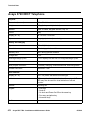
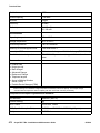
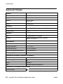
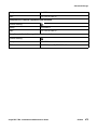
Means of Connection:
Connection of this equipment to the telephone network is shown in the
following table:
Manufacturer’s FIC Code
Port Identifier
Off premises
OL13C
station
DID trunk
02RV2.T
CO trunk
Tie trunk
Basic Rate
Interface
1.544 digital
interface
120A4 channel
service unit
02GS2
02LS2
TL31M
02IS5
SOC/ REN/A.S. Network Jacks
Code
9.0F
RJ2GX, RJ21X,
RJ11C
AS.2
RJ2GX, RJ21X,
RJ11C
0.3A
RJ21X, RJ11C
0.3A
RJ21X, RJ11C
9.0F
RJ2GX
6.0F, 6.0Y
RJ49C
04DU9.BN
04DU9.1KN
04DU9.1SN
04DU9.DN
6.0F
6.0F
6.0F
6.0Y
RJ48C, RJ48M
RJ48C, RJ48M
RJ48C, RJ48M
RJ48C
If this equipment causes harm to the telephone network, the telephone
company will notify you in advance that temporary discontinuance of
service may be required. But if advance notice is not practical, the
telephone company will notify the customer as soon as possible. Also,
you will be advised of your right to file a complaint with the FCC if you
believe it is necessary.
The telephone company may make changes in its facilities, equipment,
operations or procedures that could affect the operation of the
equipment. If this happens, the telephone company will provide advance
notice in order for you to make necessary modifications to maintain
uninterrupted service.
If trouble is experienced with this equipment, for repair or warranty
information, please contact the Technical Service Center at
1-800-242- 2121 or contact your local Avaya representative. If the
equipment is causing harm to the telephone network, the telephone
company may request that you disconnect the equipment until the
problem is resolved.
A plug and jack used to connect this equipment to the premises wiring
and telephone network must comply with the applicable FCC Part 68
rules and requirements adopted by the ACTA. A compliant telephone
cord and modular plug is provided with this product. It is designed to be
connected to a compatible modular jack that is also compliant.
Connection to party line service is subject to state tariffs. Contact the
state public utility commission, public service commission or corporation
commission for information.
Installation and Repairs
Before installing this equipment, users should ensure that it is
permissible to be connected to the facilities of the local
telecommunications company. The equipment must also be installed
using an acceptable method of connection. The customer should be
aware that compliance with the above conditions may not prevent
degradation of service in some situations.
Repairs to certified equipment should be coordinated by a representative
designated by the supplier. It is recommended that repairs be performed
by Avaya certified technicians.
FCC Part 68 Supplier’s Declarations of Conformity
Avaya Inc. in the United States of America hereby certifies that the
equipment described in this document and bearing a TIA TSB-168 label
identification number complies with the FCC’s Rules and Regulations 47
CFR Part 68, and the Administrative Council on Terminal Attachments
(ACTA) adopted technical criteria.
Avaya further asserts that Avaya handset-equipped terminal equipment
described in this document complies with Paragraph 68.316 of the FCC
Rules and Regulations defining Hearing Aid Compatibility and is deemed
compatible with hearing aids.
Copies of SDoCs signed by the Responsible Party in the U. S. can be
obtained by contacting your local sales representative and are available
on the following Web site: http://support.avaya.com/DoC.
Canadian Conformity Information
This Class A (or B) digital apparatus complies with Canadian ICES-003.
Cet appareil numérique de la classe A (ou B) est conforme à la norme
NMB-003 du Canada.
This product meets the applicable Industry Canada technical
specifications/Le présent materiel est conforme aux specifications
techniques applicables d’Industrie Canada.
European Union Declarations of Conformity
Avaya Inc. declares that the equipment specified in this document
bearing the "CE" (Conformité Europeénne) mark conforms to the
European Union Radio and Telecommunications Terminal Equipment
Directive (1999/5/EC), including the Electromagnetic Compatibility
Directive (2004/108/EC) and Low Voltage Directive (2006/95/EC).
Copies of these Declarations of Conformity (DoCs) can be obtained by
contacting your local sales representative and are available on the
following Web site: http://support.avaya.com/DoC.
European Union Battery Directive
Avaya Inc. supports European Union Battery Directive 2006/66/EC.
Certain Avaya Inc. products contain lithium batteries. These batteries are
not customer or field replaceable parts. Do not disassemble. Batteries
may pose a hazard if mishandled.
Japan
The power cord set included in the shipment or associated with the
product is meant to be used with the said product only. Do not use the
cord set for any other purpose. Any non-recommended usage could lead
to hazardous incidents like fire disaster, electric shock, and faulty
operation.
本製品に同梱または付属している電源コードセットは、本製品専用で
す。本製品以外の製品ならびに他の用途で使用しないでください。火
災、感電、故障の原因となります。
If this is a Class A device:
This is a Class A product based on the standard of the Voluntary Control
Council for Interference by Information Technology Equipment (VCCI). If
this equipment is used in a domestic environment, radio disturbance may
occur, in which case, the user may be required to take corrective actions.
この装置は,情報処理装置等電波障害自主規制協議会(VCCI)の基準
に基づくクラス A 情報技術装置です。この装置を家庭環境で使用すると電波
妨害を引き起こすことがあります。この場合には使用者が適切な対策を講ず
るよう要求されることがあります。
If this is a Class B device:
This is a Class B product based on the standard of the Voluntary Control
Council for Interference from Information Technology Equipment (VCCI).
If this is used near a radio or television receiver in a domestic
environment, it may cause radio interference. Install and use the
equipment according to the instruction manual.
この装置は,情報処理装置等電波障害自主規制協議会(VCCI)の基
準に基づくクラス B 情報技術装置です。この装置は,家庭環境で使用
することを目的としていますが,この装置がラジオやテレビジョン受信
機に近接して使用されると,受信障害を引き起こすことがあります。取
扱説明書に従って正しい取り扱いをして下さい。
Downloading documents
For the most current versions of documentation, see the Avaya Support
Web site:
http://www.avaya.com/support
Contents
System Description . . . . . . . . . . . . . . . . . . . . . . . . . . . . .
17
Introduction . . . . . . . . . . . . . . . . . . . . . . . . . . . . . . . . . . . . . .
17
Avaya IP-DECT System Overview . . . . .
Supported Standards . . . . . . . . . .
System Functions . . . . . . . . . . . .
DECT Functions . . . . . . . . . . . . .
LAN/WAN . . . . . . . . . . . . . . . . .
LDAP . . . . . . . . . . . . . . . . . . .
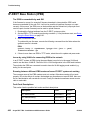
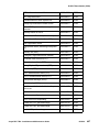
TCP/IP and UDP/IP Port Documentation
.
.
.
.
.
.
.
.
.
.
.
.
.
.
.
.
.
.
.
.
.
.
.
.
.
.
.
.
.
.
.
.
.
.
.
.
.
.
.
.
.
.
.
.
.
.
.
.
.
.
.
.
.
.
.
.
.
.
.
.
.
.
.
.
.
.
.
.
.
.
.
.
.
.
.
.
.
.
.
.
.
.
.
.
.
.
.
.
.
.
.
.
.
.
.
.
.
.
.
.
.
.
.
.
.
.
.
.
.
.
.
.
.
.
.
.
.
.
.
.
.
.
.
.
.
.
.
.
.
.
.
.
.
.
.
.
.
.
.
.
.
.
.
.
.
.
.
17
18
18
19
19
19
19
IP-DECT System . . . . . . . . . .
System layout . . . . . . . . .
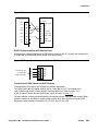
Synchronization . . . . . . . .
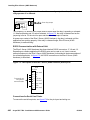
IP-DECT System Management
.
.
.
.
.
.
.
.
.
.
.
.
.
.
.
.
.
.
.
.
.
.
.
.
.
.
.
.
.
.
.
.
.
.
.
.
.
.
.
.
.
.
.
.
.
.
.
.
.
.
.
.
.
.
.
.
.
.
.
.
.
.
.
.
.
.
.
.
.
.
.
.
.
.
.
.
.
.
.
.
.
.
.
.
20
20
23
25
VoIP Signalling Protocols . . . . . . . . . . . . . . . . . . . . . . . . . . . . . . .
H.323 . . . . . . . . . . . . . . . . . . . . . . . . . . . . . . . . . . . . . . . .
26
26
IP-DECT Planning and Deployment for the IP-DECT System . . . . . . . . . . . .
27
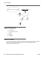
Avaya IP-DECT System Components . . . . .
DECT Cordless telephones . . . . . . . . .
IPBS. . . . . . . . . . . . . . . . . . . . . .
Communication Manager . . . . . . . . . .
Avaya In-Building Wireless Server (AIWS) .
.
.
.
.
.
27
27
27
27
28
System Capacity . . . . . . . . . . . . . . . . . . . . . . . . . . . . . . . . . . . .
28
Planning an IP- DECT System . . . . . . . . . . . . . . . . . . . . . . .
31
Introduction . . . . . . . . . . . . . . . . . . . . . . . . . . . . . . . . . . . . . .
31
Wired LAN/Backbone Requirement . . . . . . . . . . . . . . . . . . . . . . . . .
End-to-End QoS . . . . . . . . . . . . . . . . . . . . . . . . . . . . . . . . . .
32
32
Base Station Planning . . . . . . . . . . . . . . . . . . . . . . . . . . . . . . . . .
33
Client’s Requirements . . . . . . . . . . . . . . . . . . . . . . . . . . . . . . . . .
34
Base Station Coverage
Architecture . . . .
Building Elements .
Special Areas . . .
Metal Halls . . . . .
.
.
.
.
.
35
35
36
38
40
Determine the Average Cell Size . . . . . . . . . . . . . . . . . . . . . . . . . . .
43
Traffic Capacity of the System . . . . . . . . . . . . . . . . . . . . . . . . . . . .
Traffic Capacity of the Base Stations . . . . . . . . . . . . . . . . . . . . . .
45
46
Location of the Base Stations. . . . . . . . . . . . . . . . . . . . . . . . . . . . .
47
.
.
.
.
.
.
.
.
.
.
.
.
.
.
.
.
.
.
.
.
.
.
.
.
.
.
.
.
.
.
.
.
.
.
.
.
.
.
.
.
.
.
.
.
.
.
.
.
.
.
.
.
.
.
.
.
.
.
.
.
.
.
.
.
.
.
.
.
.
.
.
.
.
.
.
.
.
.
.
.
Avaya DECT R4 - Installation and Maintenance Guide
.
.
.
.
.
.
.
.
.
.
.
.
.
.
.
.
.
.
.
.
.
.
.
.
.
.
.
.
.
.
.
.
.
.
.
.
.
.
.
.
.
.
.
.
.
.
.
.
.
.
.
.
.
.
.
.
.
.
.
.
.
.
.
.
.
.
.
.
.
.
.
.
.
.
.
.
.
.
.
.
.
.
.
.
.
.
.
.
.
.
.
.
.
.
.
.
.
.
.
.
.
.
.
.
.
.
.
.
.
.
.
.
.
.
.
.
.
.
.
.
.
.
.
.
.
.
.
.
.
.
.
.
.
.
.
.
.
.
.
.
.
.
.
.
.
.
.
.
.
.
.
.
.
.
.
.
.
.
.
.
.
.
.
.
.
.
.
.
.
.
.
.
.
.
.
.
.
.
.
.
.
.
.
.
.
05/2010
5
Contents
Synchronization . . . . . .
LAN Access . . . . . . . .
Power the Base Stations .
Antennas . . . . . . . . . .
Base Station Planning Tips
.
.
.
.
.
47
47
47
48
49
Making a Base Station Plan . . . . . . . . . . . . . . . . . . . . . . . . . . . . . .
Finalizing the plan . . . . . . . . . . . . . . . . . . . . . . . . . . . . . . . . .
50
50
Installing and operating IPBS. . . . . . . . . . . . . . . . . . . . . . . .
51
Introduction . . . . . . . . . . . . . . . . . . . . . . . . . . . . . . . . . . . . . .
51
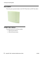
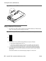
Description . . . . . . . . . . . . . . . . . . . . . . . . . . . . . . . . . . . . . . .
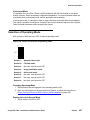
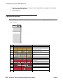
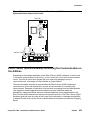
IP-DECT Base Station . . . . . . . . . . . . . . . . . . . . . . . . . . . . . . .
AC-adapter . . . . . . . . . . . . . . . . . . . . . . . . . . . . . . . . . . . . .
52
52
55
Safety Instructions. . . . . . . . . . . . . . . . . . . . . . . . . .
Safety Symbols . . . . . . . . . . . . . . . . . . . . . . . . .
Protection Against Electrostatic Discharge (ESD) . . . . . .
Safety Aspects . . . . . . . . . . . . . . . . . . . . . . . . . .
Regulatory Compliance Statements (EU/EFTA only) . . . . .
Regulatory Compliance Statements (USA and Canada only).
.
.
.
.
.
.
.
.
.
.
.
.
.
.
.
.
.
.
.
.
.
.
.
.
.
.
.
.
.
.
.
.
.
.
.
.
.
.
.
.
.
.
.
.
.
.
.
.
.
.
.
.
.
.
56
57
57
58
58
59
IP Security . . . . . . . . . . . . . . . . . .
IP Security Terminology. . . . . . . . .
Introduction to IP Security in IP-DECT .
IP-DECT Administrative functions . . .
.
.
.
.
.
.
.
.
.
.
.
.
.
.
.
.
.
.
.
.
.
.
.
.
.
.
.
.
.
.
.
.
.
.
.
.
.
.
.
.
.
.
.
.
.
.
.
.
.
.
.
.
.
.
.
.
.
.
.
.
.
.
.
.
.
.
.
.
.
.
.
.
.
.
.
.
.
.
.
.
.
.
.
.
60
60
62
63
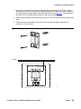
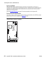
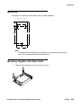
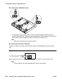
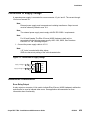
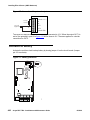
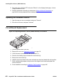
Installation of the Base Station
Base Station Cabling . . .
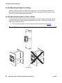
Install the Base Station . .
Power the Base Station . .
.
.
.
.
.
.
.
.
.
.
.
.
.
.
.
.
.
.
.
.
.
.
.
.
.
.
.
.
.
.
.
.
.
.
.
.
.
.
.
.
.
.
.
.
.
.
.
.
.
.
.
.
.
.
.
.
.
.
.
.
.
.
.
.
.
.
.
.
.
.
.
.
.
.
.
.
.
.
.
.
.
.
.
.
64
64
64
71
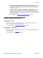
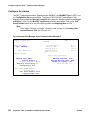
Configuration . . . . . . . . . . . . . . . . .
Requirements . . . . . . . . . . . . . . .
Access the GUI. . . . . . . . . . . . . . .
GUI Web Access . . . . . . . . . . . . . .
Configure the Master . . . . . . . . . . .
Configure the Standby Master . . . . . .
Configure the Slave/Radio . . . . . . . .
Multi Base Station Master Configuration.
Add Users . . . . . . . . . . . . . . . . .
Logout/Login Users . . . . . . . . . . . .
.
.
.
.
.
.
.
.
.
.
.
.
.
.
.
.
.
.
.
.
.
.
.
.
.
.
.
.
.
.
.
.
.
.
.
.
.
.
.
.
.
.
.
.
.
.
.
.
.
.
.
.
.
.
.
.
.
.
.
.
.
.
.
.
.
.
.
.
.
.
.
.
.
.
.
.
.
.
.
.
.
.
.
.
.
.
.
.
.
.
.
.
.
.
.
.
.
.
.
.
.
.
.
.
.
.
.
.
.
.
.
.
.
.
.
.
.
.
.
.
.
.
.
.
.
.
.
.
.
.
.
.
.
.
.
.
.
.
.
.
.
.
.
.
.
.
.
.
.
.
.
.
.
.
.
.
.
.
.
.
.
.
.
.
.
.
.
.
.
.
.
.
.
.
.
.
.
.
.
.
.
.
.
.
.
.
.
.
.
.
.
.
.
.
.
.
.
.
.
.
73
73
73
76
82
83
84
86
87
89
Operation . . . . . . . . . . . . . . . . . . . . . . . . . . . . . . . . . . . . . . . .
General . . . . . . . . . . . . . . . . . . . . . . . . . . . . . . . . . . . . . . .
LAN . . . . . . . . . . . . . . . . . . . . . . . . . . . . . . . . . . . . . . . . .
90
90
102
6
.
.
.
.
.
.
.
.
.
.
.
.
.
.
.
.
.
.
.
.
.
.
.
.
.
.
.
.
.
.
.
.
.
.
.
.
.
.
.
.
.
.
.
.
.
.
.
.
.
.
.
.
.
.
.
.
.
.
.
.
.
.
.
.
.
.
.
.
.
.
.
.
.
.
.
.
.
.
Avaya DECT R4 - Installation and Maintenance Guide
.
.
.
.
.
.
.
.
.
.
.
.
.
.
.
.
.
.
.
.
.
.
.
.
.
.
.
.
.
.
.
.
.
.
.
.
.
.
.
.
.
.
.
.
.
.
.
.
.
.
.
.
.
.
.
.
.
.
.
.
.
.
.
.
.
.
.
.
.
.
.
.
.
.
.
.
.
.
.
.
.
.
.
.
.
05/2010
Contents
IP . . . . . . . . . . . . . . . .
LDAP . . . . . . . . . . . . . .
DECT . . . . . . . . . . . . . .
UNITE . . . . . . . . . . . . . .
Users . . . . . . . . . . . . . .
Device Overview . . . . . . . .
Traffic . . . . . . . . . . . . . .
Backup . . . . . . . . . . . . .
Update . . . . . . . . . . . . .
Diagnostics. . . . . . . . . . .
Reset . . . . . . . . . . . . . .
Reset Using the Reset Button
Quit Operation . . . . . . . . .
.
.
.
.
.
.
.
.
.
.
.
.
.
.
.
.
.
.
.
.
.
.
.
.
.
.
.
.
.
.
.
.
.
.
.
.
.
.
.
.
.
.
.
.
.
.
.
.
.
.
.
.
.
.
.
.
.
.
.
.
.
.
.
.
.
.
.
.
.
.
.
.
.
.
.
.
.
.
.
.
.
.
.
.
.
.
.
.
.
.
.
105
106
109
122
124
126
128
129
129
131
135
136
136
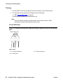
Commissioning . . . . . . . . . . . . . . . . . . . . . . . . . . . . . . . . . . . .
Radio coverage verification tests. . . . . . . . . . . . . . . . . . . . . . . . .
Cordless Extension Number Test . . . . . . . . . . . . . . . . . . . . . . . .
136
136
138
Troubleshooting . . . . . . . . . . . . . . . . . . . . . . . . . . . . . . . . . . . .
139
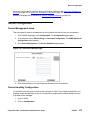
How to Use the Update Server . . . . . . . . . . . . . . . . . . . . . . . . . . . .
Summary . . . . . . . . . . . . . . . . . . . . . . . . . . . . . . . . . . . . . .
139
139
Configuring Avaya 3725/3720 telephones . . . . . . . . . . . . . . . . .
145
Introduction . . . . . . . . . . . . . . . . . . . . . . . . . . . . . . . . . . . . . .
145
Getting started with Configuration of the 3725/3720 Telephone
PDM . . . . . . . . . . . . . . . . . . . . . . . . . . . . . . .
AIWS (Avaya In-Building Wireless Server) . . . . . . . . . .
Over-the-air (OTA) via IP-DECT . . . . . . . . . . . . . . . .
.
.
.
.
.
.
.
.
.
.
.
.
.
.
.
.
.
.
.
.
.
.
.
.
.
.
.
.
.
.
.
.
.
.
.
.
.
.
.
.
145
146
146
146
Installation of Telephones . . . . . . . . . . . . . . .
Preparing PDM/AIWS for handling of 3725/3720.
Installation of a new Telephone. . . . . . . . . .
Configure a Telephone with a Template . . . . .
Synchronizing a telephone with PDM/AIWS . . .
.
.
.
.
.
.
.
.
.
.
.
.
.
.
.
.
.
.
.
.
.
.
.
.
.
.
.
.
.
.
.
.
.
.
.
.
.
.
.
.
.
.
.
.
.
.
.
.
.
.
.
.
.
.
.
.
.
.
.
.
.
.
.
.
.
.
.
.
.
.
.
.
.
.
.
.
.
.
.
.
147
147
147
149
151
Maintenance . . . . . . . . . . . . . . . . . . . .
Definitions . . . . . . . . . . . . . . . . . . .
Upgrade telephone software . . . . . . . . .
Perform a Factory reset . . . . . . . . . . . .
Replacement procedure choice guide . . . .
Easy Replacement . . . . . . . . . . . . . . .
Replacement of a telephone with the AIWS .
Replacement of the telephone with the PDM
.
.
.
.
.
.
.
.
.
.
.
.
.
.
.
.
.
.
.
.
.
.
.
.
.
.
.
.
.
.
.
.
.
.
.
.
.
.
.
.
.
.
.
.
.
.
.
.
.
.
.
.
.
.
.
.
.
.
.
.
.
.
.
.
.
.
.
.
.
.
.
.
.
.
.
.
.
.
.
.
.
.
.
.
.
.
.
.
.
.
.
.
.
.
.
.
.
.
.
.
.
.
.
.
.
.
.
.
.
.
.
.
.
.
.
.
.
.
.
.
.
.
.
.
.
.
.
.
152
152
152
152
152
153
155
157
Telephone Configuration . . . . . . . . . . . . . . . . . . . . . . . . . . . . . . .
159
Avaya DECT R4 - Installation and Maintenance Guide
.
.
.
.
.
.
.
.
.
.
.
.
.
.
.
.
.
.
.
.
.
.
.
.
.
.
.
.
.
.
.
.
.
.
.
.
.
.
.
.
.
.
.
.
.
.
.
.
.
.
.
.
.
.
.
.
.
.
.
.
.
.
.
.
.
.
.
.
.
.
.
.
.
.
.
.
.
.
.
.
.
.
.
.
.
.
.
.
.
.
.
.
.
.
.
.
.
.
.
.
.
.
.
.
.
.
.
.
.
.
.
.
.
.
.
.
.
.
.
.
.
.
.
.
.
.
.
.
.
.
.
.
.
.
.
.
.
.
.
.
.
.
.
.
.
.
.
.
.
.
.
.
.
.
.
.
.
.
.
.
.
.
.
.
.
.
.
.
.
.
.
.
.
.
.
.
.
.
.
.
.
.
.
.
.
.
.
.
.
.
.
.
.
.
.
.
.
.
.
.
.
.
.
.
.
.
.
.
.
.
.
.
.
.
.
.
.
.
.
.
.
.
.
.
.
.
.
.
.
.
.
.
.
.
.
.
.
.
.
.
.
.
.
.
.
.
.
.
.
.
.
.
.
.
.
.
.
.
.
.
.
.
.
05/2010
7
Contents
Voice Mail . . . . . . . . . . . . . . . .
Central Phonebook . . . . . . . . . . .
Company Phonebook . . . . . . . . . .
Call Services . . . . . . . . . . . . . . .
In Call Menu . . . . . . . . . . . . . . .
My Favourites . . . . . . . . . . . . . .
Own Line Settings . . . . . . . . . . . .
Uploadable Language . . . . . . . . . .
Customize the GUI . . . . . . . . . . . .
Clear Lists when inserted in Charger .
Disable Homebase GAP Registration .
Require Encrypted Base Station . . . .
Out of range beep . . . . . . . . . . . .
Handset Idle Roaming . . . . . . . . . .
Site Survey Tool . . . . . . . . . . . . .
Protect registration from user deletion
Emergency Call Number . . . . . . . .
Audio adjustment . . . . . . . . . . . .
Headset configuration . . . . . . . . . .
Owner identification in the idle display.
Profiles . . . . . . . . . . . . . . . . . .
Import Contacts . . . . . . . . . . . . .
Shortcuts . . . . . . . . . . . . . . . . .
.
.
.
.
.
.
.
.
.
.
.
.
.
.
.
.
.
.
.
.
.
.
.
.
.
.
.
.
.
.
.
.
.
.
.
.
.
.
.
.
.
.
.
.
.
.
.
.
.
.
.
.
.
.
.
.
.
.
.
.
.
.
.
.
.
.
.
.
.
.
.
.
.
.
.
.
.
.
.
.
.
.
.
.
.
.
.
.
.
.
.
.
.
.
.
.
.
.
.
.
.
.
.
.
.
.
.
.
.
.
.
.
.
.
.
.
.
.
.
.
.
.
.
.
.
.
.
.
.
.
.
.
.
.
.
.
.
.
.
.
.
.
.
.
.
.
.
.
.
.
.
.
.
.
.
.
.
.
.
.
.
.
.
.
.
.
.
.
.
.
.
.
.
.
.
.
.
.
.
.
.
.
.
.
.
.
.
.
.
.
.
.
.
.
.
.
.
.
.
.
.
.
.
.
.
.
.
.
.
.
.
.
.
.
.
.
.
.
.
.
.
.
.
.
.
.
.
.
.
.
.
.
.
.
.
.
.
.
.
.
.
.
.
.
.
.
.
.
.
.
.
.
.
.
.
.
.
.
.
.
.
.
.
.
.
.
.
.
.
.
.
.
.
.
.
.
.
.
.
.
.
.
.
.
.
.
.
.
.
.
.
.
.
.
.
.
.
.
.
.
.
.
.
.
.
.
.
.
.
.
.
.
.
.
.
.
.
.
.
.
.
.
.
.
.
.
.
.
.
.
.
.
.
.
.
.
.
.
.
.
.
.
.
.
.
.
.
.
.
.
.
.
.
.
.
.
.
.
.
.
.
.
.
.
.
.
.
.
.
.
.
.
.
.
.
.
.
.
.
.
.
.
.
.
.
.
.
.
.
.
.
.
.
.
.
.
.
.
.
.
.
.
.
.
.
.
.
.
.
.
.
.
.
.
.
.
.
.
.
.
.
.
.
.
.
.
.
.
.
.
.
.
.
.
.
.
.
.
.
.
.
.
.
.
.
.
.
.
.
.
.
.
.
.
.
.
.
.
.
.
.
.
.
.
.
.
.
.
.
.
.
.
.
.
.
.
.
.
.
.
.
.
.
159
159
159
160
161
162
163
163
164
164
165
165
166
166
166
166
166
167
167
168
168
168
169
Administration . . . . . . . . . . . . . . . . . . . . . . . . . . . . . .
Admin Menu Tree . . . . . . . . . . . . . . . . . . . . . . . . . .
Quick Access to the telephone’s Device Information/SST Menu .
LED indications . . . . . . . . . . . . . . . . . . . . . . . . . . .
Characters for SMS . . . . . . . . . . . . . . . . . . . . . . . . .
.
.
.
.
.
.
.
.
.
.
.
.
.
.
.
.
.
.
.
.
.
.
.
.
.
.
.
.
.
.
.
.
.
.
.
170
170
172
172
173
Troubleshooting . . . . . . . . . . . . . . . . . . . . . . . . . . . . . . . . . . . .
173
Configuring Avaya Aura™ Communication Manager . . . . . . . . . . .
175
General usage and Important Notes . . . . . . . . . . . . . . . . . . . . . . . . .
175
Communication Manager system administration . . . . . . . . . . . . . . . . . .
177
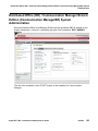
Distributed Office (DO) / Communication Manager Branch Edition (Communication
ManagerBE) System Administration . . . . . . . . . . . . . . . . . . . . . . . .
193
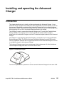
Installing and operating the Advanced Charger. . . . . . . . . . . . . .
195
Introduction . . . . . . . . . . . . . . . . . . . . . . . . . . . . . . . . . . . . . .
Safety . . . . . . . . . . . . . . . . . . . . . . . . . . . . . . . . . . . . . . . .
Technical Solution . . . . . . . . . . . . . . . . . . . . . . . . . . . . . . . . .
195
196
196
8
Avaya DECT R4 - Installation and Maintenance Guide
05/2010
Contents
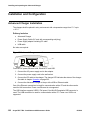
Requirements . . . . . . . . . . . . . . . . . . . . . . . . . . . . . . . . . . .
Installation and Configuration . . . .
Advanced Charger Installation . .
Advanced Charger Configuration
Security. . . . . . . . . . . . . . .
.
.
.
.
198
198
199
200
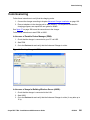
Commissioning . . . . . . . . . . . . . . . . . . . . . . . . . . . . . . . . . . . .
201
Maintenance . . . . . . . . . . . . . . . . . . . . . . . . . . . . . . . . . . . . . .
Software Update . . . . . . . . . . . . . . . . . . . . . . . . . . . . . . . . . .
202
202
Operation . . . . . . . . . . . . . . . . . . . . . . . . . . . . . . . . . . . . . . . .
Charger operation . . . . . . . . . . . . . . . . . . . . . . . . . . . . . . . . .
LED indications . . . . . . . . . . . . . . . . . . . . . . . . . . . . . . . . . .
203
203
204
Troubleshooting . . . . . . . . . . . . . . . . . . . . . . . . . . . . . . . . . . . .
205
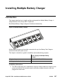
Installing Multiple Battery Charger . . . . . . . . . . . . . . . . . . . . .
207
Introduction . . . . . .
Safety . . . . . . . .
Compliance. . . . .
Technical Solution .
Avaya DECT R4 - Installation and Maintenance Guide
.
.
.
.
.
.
.
.
.
.
.
.
.
.
.
.
.
.
.
.
.
.
.
.
.
.
.
.
.
.
.
.
.
.
.
.
.
.
.
.
.
.
.
.
.
.
.
.
.
.
.
.
.
.
.
.
.
.
.
.
.
.
.
.
.
.
.
.
.
.
.
.
.
.
.
.
.
.
.
.
.
.
.
.
.
.
.
.
.
.
.
.
.
.
.
.
.
.
.
.
.
.
.
.
.
.
.
.
.
.
.
.
.
.
.
.
.
.
.
.
.
.
.
.
.
.
.
.
.
.
.
.
.
.
.
.
.
.
.
.
.
.
236
236
.
.
.
.
.
.
.
.
.
.
.
.
.
.
.
.
.
Operation . . . . . . . . . . . . . . . . . . . . . . . . . . . . . . . . . . . . . . . .
Charger Operation . . . . . . . . . . . . . . . . . . . . . . . . . . . . . . . . .
.
.
.
.
.
.
.
.
.
.
.
.
.
.
.
.
.
234
235
235
235
.
.
.
.
.
.
.
.
.
.
.
.
.
.
.
.
.
.
.
.
.
.
.
.
.
.
.
.
.
.
.
.
.
.
.
.
.
.
Commissioning . . . . . . . . . . . . .
Installation test. . . . . . . . . . . .
Charging . . . . . . . . . . . . . . .
Communication with AIWS or PDM.
.
.
.
.
.
.
.
.
.
.
.
.
.
.
.
.
.
225
225
233
.
.
.
.
.
.
.
.
.
.
.
.
.
.
.
.
.
Installation and Configuration . . . . . . . . . . . . . . . . . . . . . . . . . . . .
Rackmount Charger Installation . . . . . . . . . . . . . . . . . . . . . . . . .
Rackmount Charger Configuration . . . . . . . . . . . . . . . . . . . . . . . .
.
.
.
.
.
.
.
.
.
.
.
.
.
.
.
.
.
221
222
223
224
224
.
.
.
.
.
.
.
.
.
.
.
.
.
.
.
.
.
.
.
.
.
.
.
.
.
.
.
.
.
.
.
.
.
.
.
.
.
.
.
221
.
.
.
.
.
.
.
.
.
.
.
.
.
Installing and operating the Rackmount Charger . . . . . . . . . . . . .
.
.
.
.
.
.
.
.
.
.
.
.
.
219
.
.
.
.
.
.
.
.
.
.
.
.
.
Troubleshooting . . . . . . . . . . . . . . . . . . . . . . . . . . . . . . . . . . . .
.
.
.
.
.
.
.
.
.
.
.
.
.
219
.
.
.
.
.
.
.
.
.
.
.
.
.
Operation . . . . . . . . . . . . . . . . . . . . . . . . . . . . . . . . . . . . . . . .
.
.
.
.
.
.
.
.
.
.
.
.
.
218
.
.
.
.
.
.
.
.
.
.
.
.
.
Commissioning . . . . . . . . . . . . . . . . . . . . . . . . . . . . . . . . . . . .
.
.
.
.
.
.
.
.
.
.
.
.
.
211
211
.
.
.
.
.
.
.
.
.
.
.
.
.
Installation and Configuration . . . . . . . . . . . . . . . . . . . . . . . . . . . .
Multiple Battery Charger Installation . . . . . . . . . . . . . . . . . . . . . . .
.
.
.
.
.
.
.
.
.
.
.
.
.
207
208
209
210
.
.
.
.
.
.
.
.
.
.
.
.
.
.
.
.
.
Introduction . . . . . .
Safety . . . . . . . .
Compliance. . . . .
Technical Solution .
Requirements . . .
.
.
.
.
.
.
.
.
196
.
.
.
.
.
.
.
.
.
.
.
.
.
05/2010
9
Contents
LED indications . . . . . . . . . . . . . . . . . . . . . . . . . . . . . . . . . .
237
Maintenance . . . . . . . . . . . . . . . . . . . . . . . . . . . . . . . . . . . . . .
Software Upgrade . . . . . . . . . . . . . . . . . . . . . . . . . . . . . . . . .
238
238
Administration . . . . . . . . . . . . . . . . . . . . . . . . . . . . . . . . . . . . .
Data backup . . . . . . . . . . . . . . . . . . . . . . . . . . . . . . . . . . . .
238
238
Troubleshooting . . . . . . . . . . . . . . . . . . . . . . . . . . . . . . . . . . . .
238
Installing and operating the Portable Device Manager (PDM) . . . . . .
239
Introduction . . . . . . . . .
How to Use this Chapter
Technical Solution . . . .
Requirements . . . . . .
10
.
.
.
.
239
240
240
241
PDM description . . . . . . . . . . . . . . . . . . . . . . . . . . . . . . . . . . . .
PDM terminology . . . . . . . . . . . . . . . . . . . . . . . . . . . . . . . . .
PDM usage . . . . . . . . . . . . . . . . . . . . . . . . . . . . . . . . . . . . .
242
242
242
Installation and Configuration . . . . . . . . . . . . . . . . . . . . . . . . . . . .
Software Installation. . . . . . . . . . . . . . . . . . . . . . . . . . . . . . . .
Software Configuration . . . . . . . . . . . . . . . . . . . . . . . . . . . . . .
244
244
244
Operation . . . . . . . . . . .
The PDM GUI . . . . . . .
The New Device Wizard .
The New Number Wizard
Open the PDM . . . . . .
Site Management . . . .
Numbers . . . . . . . . .
Devices . . . . . . . . . .
File management. . . . .
Import and Export . . . .
Close the PDM . . . . . .
.
.
.
.
.
.
.
.
.
.
.
248
248
252
254
256
256
258
265
268
276
278
Administration . . . . . . . . . . . . . . . . . . . . . . . . . . . . . . . . . . . . .
Data Backup . . . . . . . . . . . . . . . . . . . . . . . . . . . . . . . . . . . .
Templates . . . . . . . . . . . . . . . . . . . . . . . . . . . . . . . . . . . . .
279
279
279
Troubleshooting . . . . . . . . . . . . . . . . . . . . . . . . . . . . . . . . . . . .
284
Uninstall the PDM . . . . . . . . . . . . . . . . . . . . . . . . . . . . . . . . . . .
285
PDM Keyboard shortcuts
General . . . . . . . .
Devices . . . . . . . .
Numbers . . . . . . .
Templates . . . . . .
286
286
286
286
287
.
.
.
.
.
.
.
.
.
.
.
.
.
.
.
.
.
.
.
.
.
.
.
.
.
.
.
.
.
.
.
.
.
.
.
.
.
.
.
.
.
.
.
.
.
.
.
.
.
.
.
.
.
.
.
.
.
.
.
.
.
.
.
.
.
.
.
.
.
.
.
.
.
.
.
.
.
.
.
.
.
.
.
.
.
.
.
.
.
.
.
.
.
.
.
.
.
.
.
.
.
.
.
.
.
.
.
.
.
.
.
.
.
.
.
.
.
.
.
.
.
.
.
.
.
.
.
.
.
.
.
.
.
.
.
.
.
.
.
.
.
.
.
.
.
.
.
.
.
.
.
.
.
.
.
.
.
.
.
.
.
.
.
.
.
.
.
.
.
.
.
.
.
.
.
.
.
.
.
.
.
.
.
.
.
.
.
.
.
.
.
.
.
.
.
.
.
.
.
.
.
.
.
.
.
.
.
.
.
.
.
.
.
.
.
.
.
.
.
.
.
.
.
.
.
.
.
.
.
.
.
.
.
.
.
.
.
.
.
.
.
.
.
.
.
.
.
.
.
.
Avaya DECT R4 - Installation and Maintenance Guide
.
.
.
.
.
.
.
.
.
.
.
.
.
.
.
.
.
.
.
.
.
.
.
.
.
.
.
.
.
.
.
.
.
.
.
.
.
.
.
.
.
.
.
.
.
.
.
.
.
.
.
.
.
.
.
.
.
.
.
.
.
.
.
.
.
.
.
.
.
.
.
.
.
.
.
.
.
.
.
.
.
.
.
.
.
.
.
.
.
.
.
.
.
.
.
.
.
.
.
.
.
.
.
.
.
.
.
.
.
.
.
.
.
.
.
.
.
.
.
.
.
.
.
.
.
.
.
.
.
.
.
.
.
.
.
.
.
.
.
.
.
.
.
.
.
.
.
.
.
.
.
.
.
.
.
.
.
.
.
.
.
.
.
.
.
.
.
.
.
.
.
.
.
.
.
.
.
.
.
.
.
.
.
.
.
.
.
.
.
.
.
.
.
.
.
.
.
.
.
.
.
.
.
.
.
.
.
.
.
.
.
.
.
.
.
.
.
.
.
.
.
.
.
.
.
.
.
.
.
.
.
.
.
.
.
.
.
.
.
.
.
.
.
.
.
.
.
.
.
.
.
.
.
.
.
.
.
.
.
.
.
.
.
.
.
.
.
.
.
.
.
.
.
.
.
.
.
.
.
.
.
.
.
.
.
.
.
.
.
.
.
.
.
.
.
.
.
.
.
.
.
.
.
.
.
.
.
.
.
.
.
.
.
.
.
.
.
.
.
.
.
.
.
.
.
05/2010
Contents
File types . . . . . . . . . . . . . . . . . . . . . . . . . . . . . . . . . . . . . . . .
288
Installing and operating AIWS . . . . . . . . . . . . . . . . . . . . . . .
289
Introduction . . . . . . . . .
Items . . . . . . . . . . .
Overview . . . . . . . . .
How to Use this Chapter
Included in the delivery .
Technical Solution . . . .
Requirements . . . . . .
.
.
.
.
.
.
.
.
.
.
.
.
.
.
.
.
.
.
.
.
.
.
.
.
.
.
.
.
.
.
.
.
.
.
.
.
.
.
.
.
.
.
.
.
.
.
.
.
.
.
.
.
.
.
.
.
.
.
.
.
.
.
.
.
.
.
.
.
.
.
.
.
.
.
.
.
.
.
.
.
.
.
.
.
.
.
.
.
.
.
.
.
.
.
.
.
.
.
.
.
.
.
.
.
.
.
.
.
.
.
.
.
.
.
.
.
.
.
.
.
.
.
.
.
.
.
.
.
.
.
.
.
.
.
.
.
.
.
.
.
289
290
290
291
293
293
293
Installation and Configuration . . . . . . . . . . . . . .
Required Information . . . . . . . . . . . . . . . . .
Hardware Installation and Configuration. . . . . . .
Software Installation. . . . . . . . . . . . . . . . . .
Configuration . . . . . . . . . . . . . . . . . . . . .
Mounting . . . . . . . . . . . . . . . . . . . . . . . .
Update of AIWS . . . . . . . . . . . . . . . . . . . .
Multiple AIWS configuration . . . . . . . . . . . . .
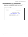
AIWS configuration for Multi Base Station Masters .
.
.
.
.
.
.
.
.
.
.
.
.
.
.
.
.
.
.
.
.
.
.
.
.
.
.
.
.
.
.
.
.
.
.
.
.
.
.
.
.
.
.
.
.
.
.
.
.
.
.
.
.
.
.
.
.
.
.
.
.
.
.
.
.
.
.
.
.
.
.
.
.
.
.
.
.
.
.
.
.
.
.
.
.
.
.
.
.
.
.
.
.
.
.
.
.
.
.
.
.
.
.
.
.
.
.
.
.
.
.
.
.
.
.
.
.
.
.
.
.
.
.
.
.
.
.
294
294
294
294
295
295
295
296
302
Administration . . . . . . . . . . . . . . . . . . . . . . . . . . . . . . . . . . . . .
Data Backup . . . . . . . . . . . . . . . . . . . . . . . . . . . . . . . . . . . .
304
304
AIWS General . . . . . . . . . . . . . . . . . . . .
Authentication Levels and Default Passwords
Functionality matrix . . . . . . . . . . . . . . .
Set passwords . . . . . . . . . . . . . . . . . .
Password policy . . . . . . . . . . . . . . . . .
Web access security settings. . . . . . . . . .
Configuration Page . . . . . . . . . . . . . . .
Icons . . . . . . . . . . . . . . . . . . . . . . .
Certificates . . . . . . . . . . . . . . . . . . . .
.
.
.
.
.
.
.
.
.
305
305
306
306
306
307
308
309
309
AIWS Setup Wizard and Configuration. . . . . . . . . . . . . . . . . . . . . . . .
Basic Configuration Steps . . . . . . . . . . . . . . . . . . . . . . . . . . . .
Optional Settings . . . . . . . . . . . . . . . . . . . . . . . . . . . . . . . . .
312
312
313
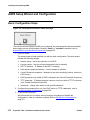
Operation - Messaging . . . . . . .
Messaging Tool . . . . . . . . .
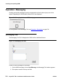
NetPage. . . . . . . . . . . . . .
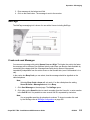
Phonebook Administration . . .
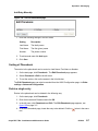
Phonebook Editing . . . . . . .
Import and Export a Phonebook
.
.
.
.
.
.
314
314
315
316
316
319
Device Manager . . . . . . . . . . . . . . . . . . . . . . . . . . . . . . . . . . . .
322
.
.
.
.
.
.
.
.
.
.
.
.
.
.
.
.
.
.
.
.
.
.
.
.
.
.
.
.
.
.
.
.
.
.
.
.
.
.
.
.
.
.
.
.
.
.
.
.
.
.
.
.
.
.
.
.
.
.
Avaya DECT R4 - Installation and Maintenance Guide
.
.
.
.
.
.
.
.
.
.
.
.
.
.
.
.
.
.
.
.
.
.
.
.
.
.
.
.
.
.
.
.
.
.
.
.
.
.
.
.
.
.
.
.
.
.
.
.
.
.
.
.
.
.
.
.
.
.
.
.
.
.
.
.
.
.
.
.
.
.
.
.
.
.
.
.
.
.
.
.
.
.
.
.
.
.
.
.
.
.
.
.
.
.
.
.
.
.
.
.
.
.
.
.
.
.
.
.
.
.
.
.
.
.
.
.
.
.
.
.
.
.
.
.
.
.
.
.
.
.
.
.
.
.
.
.
.
.
.
.
.
.
.
.
.
.
.
.
.
.
.
.
.
.
.
.
.
.
.
.
.
.
.
.
.
.
.
.
.
.
.
.
.
.
.
.
.
.
.
.
.
.
.
.
.
.
.
.
.
.
.
.
.
.
.
.
.
.
.
.
.
.
.
.
.
.
.
.
.
.
.
.
.
.
.
.
.
.
.
.
.
.
.
.
.
.
.
.
.
.
.
.
.
.
.
.
.
.
.
.
.
.
.
.
.
.
.
.
.
.
.
.
.
.
.
.
.
.
.
.
.
.
.
.
.
.
.
.
.
.
.
.
.
.
.
.
.
.
.
.
.
.
.
.
.
.
.
.
.
.
.
.
.
05/2010
11
Contents
Device Manager description .
Log In . . . . . . . . . . . . . .
Templates in Device Manager.
Numbers . . . . . . . . . . . .
Devices . . . . . . . . . . . . .
File management. . . . . . . .
Import and Export . . . . . . .
Other Settings . . . . . . . . .
Close the Device Manager . .
12
.
.
.
.
.
.
.
.
.
.
.
.
.
.
.
.
.
.
.
.
.
.
.
.
.
.
.
.
.
.
.
.
.
.
.
.
322
329
329
333
338
342
352
353
354
DECT Interface . . . . . . . . . . . . . . . . . . . . . . . . . . . . . . . . . . . . .
Cordless Telephone System . . . . . . . . . . . . . . . . . . . . . . . . . . .
DECT Interface settings . . . . . . . . . . . . . . . . . . . . . . . . . . . . . .
355
355
356
Basic Configuration . . . . . . . . . .
Central Phonebook Configuration
Status . . . . . . . . . . . . . . . .
Backup the Configuration . . . . .
Restore the Configuration. . . . .
Device Configuration . . . . . . .
Additional System Settings . . . .
.
.
.
.
.
.
.
358
358
369
373
374
375
377
Absence Handling . . . . . . . . . . . . . . . . . . . . . . . . . . . . . . . . . . .
384
Remote Management . . . . . . . . . . . . . . . . . . . . . . . . . . . . . . . . .
384
Language and User Interface . . . . . . . . . . . . . . .
Customize the Language . . . . . . . . . . . . . . .
Customize the User Interface (GUI). . . . . . . . . .
Password Protected Access to NetPage . . . . . . .
Accessing NetPage from a Cordless Unit with WAP
Test the New User Interface. . . . . . . . . . . . . .
Update the User Interface after a new AIWS Release
.
.
.
.
.
.
.
.
.
.
.
.
.
.
.
.
.
.
.
.
.
.
.
.
.
.
.
.
.
.
.
.
.
.
.
.
.
.
.
.
.
.
.
.
.
.
.
.
.
.
.
.
.
.
.
.
.
.
.
.
.
.
.
.
.
.
.
.
.
.
.
.
.
.
.
.
.
.
.
.
.
.
.
.
.
.
.
.
.
.
.
.
.
.
.
.
.
.
386
387
391
400
400
401
401
Messaging Tool Configuration . . . . . .
Messaging Tool Configuration . . . .
NetPage Configuration . . . . . . . .
Predefined Groups. . . . . . . . . . .
Predefined Messages . . . . . . . . .
Message History Status . . . . . . . .
Backup and Restore of NetPage files
.
.
.
.
.
.
.
.
.
.
.
.
.
.
.
.
.
.
.
.
.
.
.
.
.
.
.
.
.
.
.
.
.
.
.
.
.
.
.
.
.
.
.
.
.
.
.
.
.
.
.
.
.
.
.
.
.
.
.
.
.
.
.
.
.
.
.
.
.
.
.
.
.
.
.
.
.
.
.
.
.
.
.
.
.
.
.
.
.
.
.
.
.
.
.
.
.
.
402
402
402
405
406
407
408
Open Access Protocol (OAP) . . . . . . . . . . . . . . . . . . . . . . . . . . . . .
Configuration . . . . . . . . . . . . . . . . . . . . . . . . . . . . . . . . . . .
410
410
Troubleshooting . . . . . . . . . . . . . . . . . . . . . . . . . . . . . . . . . . . .
411
Getting Started . . . . . . . . . . . . . . . . . . . . . . . . . . . . . . . . . . . . .
412
.
.
.
.
.
.
.
.
.
.
.
.
.
.
.
.
.
.
.
.
.
.
.
.
.
.
.
.
.
.
.
.
.
.
.
.
.
.
.
.
.
.
.
.
.
.
.
.
.
.
.
.
.
.
.
.
.
.
.
.
.
.
.
.
.
.
.
.
.
.
.
.
.
.
.
.
.
.
.
.
.
.
.
.
.
.
.
.
.
.
.
.
.
.
.
.
.
.
.
.
.
.
.
.
.
.
.
.
.
.
.
.
.
.
.
.
.
.
.
.
.
.
.
.
.
.
.
.
.
.
.
.
.
.
.
.
.
.
Avaya DECT R4 - Installation and Maintenance Guide
.
.
.
.
.
.
.
.
.
.
.
.
.
.
.
.
.
.
.
.
.
.
.
.
.
.
.
.
.
.
.
.
.
.
.
.
.
.
.
.
.
.
.
.
.
.
.
.
.
.
.
.
.
.
.
.
.
.
.
.
.
.
.
.
.
.
.
.
.
.
.
.
.
.
.
.
.
.
.
.
.
.
.
.
.
.
.
.
.
.
.
.
.
.
.
.
.
.
.
.
.
.
.
.
.
.
.
.
.
.
.
.
.
.
.
.
.
.
.
.
.
.
.
.
.
.
.
.
.
.
.
.
.
.
.
.
.
.
.
.
.
.
.
.
.
.
.
.
.
.
.
.
.
.
.
.
.
.
.
.
.
.
.
.
.
.
.
.
.
.
.
.
.
.
.
.
.
.
.
.
.
.
.
.
.
.
.
.
.
.
.
.
.
.
.
.
.
.
.
.
.
.
.
.
.
.
.
.
.
.
.
.
.
.
.
.
.
.
.
.
.
.
.
.
.
.
.
.
.
.
.
.
.
.
.
.
.
.
.
.
.
.
.
.
.
.
.
.
.
.
.
.
.
.
.
.
.
.
.
.
.
.
.
.
.
.
.
.
.
.
.
.
.
.
.
.
.
05/2010
Contents
Device Manager Keyboard Shortcuts
General . . . . . . . . . . . . . . .
Devices . . . . . . . . . . . . . . .
Numbers . . . . . . . . . . . . . .
Templates . . . . . . . . . . . . .
.
.
.
.
.
.
.
.
.
.
.
.
.
.
.
.
.
.
.
.
.
.
.
.
.
.
.
.
.
.
.
.
.
.
.
.
.
.
.
.
.
.
.
.
.
.
.
.
.
.
.
.
.
.
.
.
.
.
.
.
.
.
.
.
.
.
.
.
.
.
.
.
.
.
.
.
.
.
.
.
.
.
.
.
.
415
415
415
415
416
Function Indicator and Error Relay Output . . . . . . . . . . . . . . . . . . . . .
417
File types . . . . . . . . . . . . . . . . . . . . . . . . . . . . . . . . . . . . . . . .
418
Installing Elise 2 Server (AIWS Hardware) . . . . . . . . . . . . . . . . .
421
Introduction . . . . . . . . . . . . . . . . . . . . . . . . . . . . . . . . . . . . . .
FCC Compliance Statements for Class A Digital Device . . . . . . . . . . . .
EU Compliance Statements for Class A Device . . . . . . . . . . . . . . . . .
421
422
422
Board Description . . . . . . . . . . . . . . . . . . . . . . . . . . . . . . . . . . .
423
General Information . . . . . . . . . . . . . . . . . . . . . . . . .
Licence . . . . . . . . . . . . . . . . . . . . . . . . . . . . . .
Power Down and Restart of Elise 2 Server (AIWS Hardware)
Operating Modes. . . . . . . . . . . . . . . . . . . . . . . . .
Selection of Operating Mode . . . . . . . . . . . . . . . . . .
Function Indicator . . . . . . . . . . . . . . . . . . . . . . . .
Administration and Authentication . . . . . . . . . . . . . . .
425
425
425
426
427
428
429
.
.
.
.
.
.
.
.
.
.
.
.
.
.
.
.
.
.
.
.
.
.
.
.
.
.
.
.
.
.
.
.
.
.
.
.
.
.
.
.
.
.
.
.
.
.
.
.
.
.
.
.
.
.
.
.
.
.
.
.
.
.
.
.
.
.
.
.
.
.
.
.
.
.
.
.
.
.
.
.
.
.
.
.
.
.
.
.
.
.
.
.
.
.
.
.
.
.
Installation . . . . . . . . . . . . . . . . . . . . . . . . . . . . . . . . . . . . . . .
430
Opening the Housing . . . . . . . . . . . . . . . . . . . . . . . . . . . . . . .
431
Wiring Runs . . . . . . . . . . . . . . . . . . . . . . . . . . . . . . . . . . . .
431
Selection of A or B-bus . . . . . . . . . . . . . . . . . . . . . . . . . . . . . .
432
Elise 2 Server (AIWS Hardware) controlling the Communication on the A/B-bus 433
Mounting . . . . . . . . . . . . . . . . . . . . . . . . . . . . . . . . . . . . . .
435
Mounting Together with Other Units . . . . . . . . . . . . . . . . . . . . . . .
435
System 900 Addressing . . . . . . . . . . . . . . . . . . . . . . . . . . . . . .
436
Connection of System Bus . . . . . . . . . . . . . . . . . . . . . . . . . . . .
437
Connection of Supply Voltage . . . . . . . . . . . . . . . . . . . . . . . . . .
439
Additional Connections . . . . . . . . . . . . . . . . . . . . . . . . . . . . . .
439
Activation of Battery . . . . . . . . . . . . . . . . . . . . . . . . . . . . . . .
442
Connection of Ethernet . . . . . . . . . . . . . . . . . . . . . . . . . . . . . .
443
Setup of Network Parameters. . . . . . . . . . . . . . . . . . . . . . . . . . .
444
Installation Test Procedure . . . . . . . . . . . . . . . . . . . . . . . . . . . .
445
Clock Synchronisation and Time Settings . . . . . . . . . . . . . . . . . . . .
446
Message Distribution . . . . . . . . . . . . . . . . . . . . . . . . . . . . . . .
447
Unite Name Server (UNS) . . . . . . . . . . . . . . . . . . . . . . . . . . . . .
449
Maintenance Information . . . . . . . . . . . . . . . . . . . . . . . . . . . . . . .
Replacement of the Compact Flash . . . . . . . . . . . . . . . . . . . . . . .
Avaya DECT R4 - Installation and Maintenance Guide
449
449
05/2010
13
Contents
Updating Application Software . . . . . . . . . .
Replacing an Image on the Compact Flash . . .
Installing an Image on an empty Compact Flash
Updating the Software Licence . . . . . . . . . .
Circuit Board Replacement . . . . . . . . . . . .
.
.
.
.
.
449
450
451
452
452
LON Piggy Back Circuit Board (LPB). . . . . . . . . . . . . . . . . . . . . . . . .
453
Technical Data . . . . . . . . . . . . . . . . . . . . . . . . . . . . . . . .
457
Introduction . . . . . . . . . . . . . . . . . . . . . . . . . . . . . . . . . . . . . .
457
IP-DECT Base Station (IPBS) . . . . . . . . . . . . . . . . . . . . . . . . . . . . .
458
Base Station RM627 (BS330) . . . . . . . . . . . . . . . . . . . . . . . . . . . . .
460
Base Station RM637 (BS340) . . . . . . . . . . . . . . . . . . . . . . . . . . . . .
462
Avaya 3725 DECT Telephone . . . . . . . . . . . . . . . . . . . . . . . . . . . . .
464
Avaya 3720 DECT Telephone . . . . . . . . . . . . . . . . . . . . . . . . . . . . .
470
Advanced Charger . . . . . . . . . . . . . . . . . . . . . . . . . . . . . . . . . . .
474
Basic Charger . . . . . . . . . . . . . . . . . . . . . . . . . . . . . . . . . . . . .
476
Multiple Battery Charger . . . . . . . . . . . . . . . . . . . . . . . . . . . . . . .
478
Rackmount Charger . . . . . . . . . . . . . . . . . . . . . . . . . . . . . . . . . .
480
Portable Device Manager (PDM) . . . . . . . . . . . . . . . . . . . . . . . . . . .
482
Avaya In-Building Wireless Server (AIWS) . . . . . . . . . . . . . . . . . . . . . .
Variants. . . . . . . . . . . . . . . . . . . . . . . . . . . . . . . . . . . . . . .
483
485
Omnidirectional single antenna . . . . . . . . . . . . . . . . . . . . . . . . . . .
487
Directional dual antenna . . . . . . . . . . . . . . . . . . . . . . . . . . . . . . .
489
Directional single antenna . . . . . . . . . . . . . . . . . . . . . . . . . . . . . .
491
Outdoor housing DECT base stations . . . . . . . . . . . . . . . . . . . . . . . .
493
Troubleshooting . . . . . . . . . . . . . . . . . . . . . . . . . . . . . . .
495
Introduction . . . . . . . . . . . . . . . . . . . . . . . . . . . . . . . . . . . . . .
495
IP-DECT Base Station (IPBS) . . . . . . . . . . . . . . . . . . . . . . . . . . . . .
496
Remote LAN sniffer traces . . . . . . . . . . . . . . . . . . . . . . . . . . . . . .
498
Avaya 3720/3725 DECT Telephones
Fault Symptoms . . . . . . . . .
Display Information . . . . . . .
LED Error Indications . . . . . .
.
.
.
.
500
500
502
504
Advanced Charger . . . . . . . . . . . . . . . . . . . . . . . . . . . . . . . . . . .
505
Multiple Battery Charger . . . . . . . . . . . . . . . . . . . . . . . . . . . . . . .
506
Rackmount Charger . . . . . . . . . . . . . . . . . . . . . . . . . . . . . . . . . .
507
14
.
.
.
.
.
.
.
.
.
.
.
.
.
.
.
.
.
.
.
.
.
.
.
.
.
.
.
.
.
.
.
.
Avaya DECT R4 - Installation and Maintenance Guide
.
.
.
.
.
.
.
.
.
.
.
.
.
.
.
.
.
.
.
.
.
.
.
.
.
.
.
.
.
.
.
.
.
.
.
.
.
.
.
.
.
.
.
.
.
.
.
.
.
.
.
.
.
.
.
.
.
.
.
.
.
.
.
.
.
.
.
.
.
.
.
.
.
.
.
.
.
.
.
.
.
.
.
.
.
.
.
.
.
.
.
.
.
.
.
.
.
.
.
.
.
.
.
.
.
.
.
.
.
.
.
.
.
.
.
.
.
.
.
.
.
.
.
.
.
.
.
.
.
.
.
.
.
.
.
.
.
.
.
05/2010
Contents
Portable Device Manager (PDM) . . . . . . . . . . . . . . . . . . . . . . . . . . .
509
Avaya In-Building Wireless Server (AIWS) . . . . . . . . . . . . .
General Troubleshooting . . . . . . . . . . . . . . . . . . . .
NetPage Troubleshooting . . . . . . . . . . . . . . . . . . . .
Reboot after image installation w/o restoring the parameters
Built-in tools in AIWS . . . . . . . . . . . . . . . . . . . . . .
Advanced Troubleshooting . . . . . . . . . . . . . . . . . . .
AIWS factory reset . . . . . . . . . . . . . . . . . . . . . . . .
What to consider when replacing a module . . . . . . . . . .
.
.
.
.
.
.
.
.
511
511
513
514
514
516
517
518
. . . . . . . . . . . . . . . . . . . . . . . . . . . . . . . . . .
519
Related Documents . . . . . . . . . . . . . . . . . . . . . . . . . . . . . . . . . .
523
Glossary
Index
.
.
.
.
.
.
.
.
.
.
.
.
.
.
.
.
.
.
.
.
.
.
.
.
.
.
.
.
.
.
.
.
.
.
.
.
.
.
.
.
.
.
.
.
.
.
.
.
.
.
.
.
.
.
.
.
.
.
.
.
.
.
.
.
. . . . . . . . . . . . . . . . . . . . . . . . . . . . . . . . . .
Avaya DECT R4 - Installation and Maintenance Guide
525
05/2010
15
Contents
16
Avaya DECT R4 - Installation and Maintenance Guide
05/2010
System Description
Introduction
This chapter gives a general description of the Avaya IP-DECT System, an IP based cordless
telephony and messaging system for connection to private telephone exchanges.
The IP-DECT system supports the DECT standard which gives a full integration of messaging
and voice functions. The DECT-system can be integrated with external applications such as
different alarm systems. This gives features such as; messages to telephone, alarm from
telephone, message acknowledgement, and absent handling.
Avaya IP-DECT System Overview
The Avaya IP-DECT System enables extended sales opportunities for on-site wireless
communication. For example, IP-DECT enables cost efficient smaller systems, with modularity
up to very large installations, feature rich distributed system installations (local office/site) and a
wide variety of modern connection possibilities.
The Avaya IP-DECT system is built up by the following components:
●
DECT Cordless Telephones
●
IP-DECT Base Station (IPBS)
●
Avaya Aura™ Communication Manager
●
Avaya In-Building Wireless Server (AIWS), optional
Avaya DECT R4 - Installation and Maintenance Guide
05/2010
17
System Description
Figure 1: IP-DECT System Overview
PSTN (Public Switched Telephone Network)
CM
LAN
AIWS
AIW
IPBS
001
IPBS
Supported Standards
●
H.323 XMobile
●
G.711 (a-law and mu-law)
●
G.723-53
●
G.726-32
●
G.729-A/AB
System Functions
The Avaya IP-DECT system is designed to enable voice traffic, messaging and alarm handling
between cordless telephones within an enterprise LAN. For details see the Function
Description, Avaya IP-DECT System.
18
Avaya DECT R4 - Installation and Maintenance Guide
05/2010
Avaya IP-DECT System Overview
DECT Functions
DECT is a digital wireless technology which originated in Europe, but is now being adopted
increasingly worldwide, for cordless telephones, wireless offices and even wireless telephone
lines to the home. DECT has been designed and specified to interwork with many other types of
network, such as the PSTN, ISDN and GSM.
Common IP-DECT functions are handled entirely within the IP-DECT system.
Roaming and Handover
The IP-DECT system supports roaming between all IPBSs in the system. It also supports
handover if there is overlapping speech coverage.
LAN/WAN
There are several vendors providing components needed to deploy a LAN/WAN. In order to
achieve optimal performance for IP-DECT the following is recommended:
●
Quality of Service (QoS)
●
The infrastructure should be connected to a switched network. (i.e hubs or repeaters
should be avoided)
●
Depending on network size, a backbone of least 100 Mbps should be used.
LDAP
The LDAP protocol is used in the IP-DECT system between two or more Master IPBS if
different network regions shall be used. It is also used for Standby Master.
TCP/IP and UDP/IP Port Documentation
For detailed information, please ask your Avaya contact for document CID 139993.
Avaya DECT R4 - Installation and Maintenance Guide
05/2010
19
System Description
IP-DECT System
The major parts of the Avaya IP-DECT system are the IP-DECT Base Station. It consists of the
software components DECT Radio (interface) and DECT Master.
There is only one DECT Master in a single site IP-DECT system. In a multi-site IP-DECT
system, each site is connected with the Communication Manager through an own DECT Master
and an XMobile trunk.
Figure 2: Software components of the IPBS
DECT Master
007
DECT Radio
IPBS
The IPBS is connected to an IP network through the LAN interface, which provides connectivity
to the Communication Manager.
System layout
All IPBS are connected to the LAN but it is only the DECT Master that have a logical connection
to the Communication Manager. It is a flat layout where all DECT Radios are logically
communicating directly to the DECT Master, see figure 3 on page 21.
Figure 1.
20
Avaya DECT R4 - Installation and Maintenance Guide
05/2010
IP-DECT System
Figure 3: Logical connections of the software components DECT Master and DECT Radio
CM
DECT
Radio
DECT
Master
DECT
Radio
DECT
Master
DECT
Radio
DECT
Master
DECT
Radio
DECT
Master
DECT
Radio
002
DECT
Master
DECT Master
The DECT Master is a software interface between the IP-DECT system and the Communication
Manager. The DECT Master is responsible for all DECT telephones in the system.
The DECT Master knows which DECT Radio the telephones are located to, that is which DECT
Radio in the system that received the latest location registration message from the telephone. A
call to a telephone is directed only to the DECT Radio where the telephone is located. Thus
limiting the H.323 XMobile and DECT load in the system.
DECT Radio
The DECT Radio is a software interface between DECT and H.323 XMobile. A DECT Radio
always communicates with one DECT Master. The DECT Radio only has information of the
DECT telephone which currently are on the same radio channel.
Single Site Installation Example Layout
The layout in figure 4 can be used for customers with a single site installation.
Figure 2.
Avaya DECT R4 - Installation and Maintenance Guide
05/2010
21
System Description
Figure 4: Single site layout with one IP-DECT Master
CM
One single site
DECT Master
DECT Radio
“many”
DECT Radio
003
DECT Radio
The lines displayed between the Communication Manager, the DECT Master and the DECT
Radios in figure 4 are used to indicate the logical connection between the software modules.
Note:
Note:
The figure shows the software components. An IPBS includes both the software
components DECT Master and DECT Radio.
One IPBS must be assigned the role as master, this IPBS can also act as a DECT Radio and
will have an active DECT Radio and an active DECT Master software component. All other
IPBS will only have the software component "DECT Radio" active. The software component
"DECT Master" will only be active in the Master, in all other it will be deactivated.
Multiple site installation
The layout as in a single site can also be used for customers with an installation on several
sites. The sites may have one DECT Master per site and one or several IPBSs at each site. The
Communication Manager is centrally located (may be one of the sites), see figure 5.
Figure 5: Multiple site layout with one IP-DECT Master per site
CM
XM
le
obi
XM
obi
Site 1
Site 2
DECT Master
DECT Radio
DECT Radio
LDAP
DECT Master
DECT Radio
DECT Radio
DECT Radio
004
DECT Radio
le
22
Avaya DECT R4 - Installation and Maintenance Guide
05/2010
IP-DECT System
The lines displayed between the Communication Manager, respective the DECT Master and
the DECT Radios in figure 5 are used to indicate the logical connection between the software
modules.
Note:
The figure shows the software components. An IPBS includes both the software
components DECT Master and DECT Radio.
Note:
External handover is only possible to do within each site, not between them.
Synchronization
Synchronization within the IP-DECT system is done by:
●
Air synchronization (IPBS)
Air Synchronization
IP-DECT base stations uses the DECT air interface to synchronize to each other. This makes it
possible to fulfil the CAP standard and to use the existing portables.
One IPBS is configured as a synchronization master. From this sync master all other IPBSs
adjust there internal crystal oscillator to have the same frequency drift as the master. This does
not mean all IPBSs need to be within coverage of the master base, a IPBS running in slave
mode can synchronize to another IPBS in slave mode.
It is not needed to configure what IPBS to synchronize to. This is handled automatically by
introducing a proprietary message sent from the IPBSs (called "air sync hop").
Avaya DECT R4 - Installation and Maintenance Guide
05/2010
23
System Description
Figure 6: Air- and speech sync radius.
-80 dBm
-68 dBm
-68 dBm
-80 dBm
Air Sync Coverage
005
Speech Coverage
Figure 3.
As a single IPBS failure may spread to other IPBSs it is needed, for critical systems, to install
the IPBSs to always be within coverage of at least two alternative IPBSs receiving sync from.
It is also possible to configure one backup sync masters in case of failure of the sync master.
Speech radius: the radius of the circle (circular radiation patterns of the IPBS antennas are
assumed), around a particular IPBS, in which portable parts can communicate with that IPBS,
see figure 6.
Note:
Note:
It is recommended to have at least -68 dBm for good speech quality. The -68 dBm
circles should overlap to ensure seemless handover between 2 base stations
(The handset should receive the next base station with -62 dBm at the -68 dBm
circle of the first base station).
Sync radius: the radius of the circle, around a particular IPBS, in which other IPBSs lose
synchronization with that IPBS with a given synchronization loss probability. This means that
the size of the sync radius depends on requested probability of losing synchronization, see
figure 6.
Note:
24
Note:
A value of -80 dBm is a recommendation to ensure good sync conditions.
Avaya DECT R4 - Installation and Maintenance Guide
05/2010
IP-DECT System
IP-DECT System Management
On Site Management
The IPBS is managed using a web GUI accessed over the LAN.
Remote Management
The IPBS has support for remote setup and configuration over the Internet using a VPN client
over IP networks.
IP Administration Security
All IP administration is based on secure IP. All access to the IPBS is password protected in
order to prevent unauthorised access.
Software Upgrade
The IPBS has support for software download and it is possible to do a software upgrade using
the web interface. It also has support for automatic firmware update from a web server or a
TFTP server.
Avaya DECT R4 - Installation and Maintenance Guide
05/2010
25
System Description
VoIP Signalling Protocols
The protocol used for VoIP signalling is H.323 XMobile which is a proprietary extension of
H.323. H.323 is in fact a set of protocols designed to enable multimedia traffic in single LANs.
H.323
H.323 was developed by the International Telecommunications Union (ITU) and was designed
from a telecommunications perspective. Ratified in 1996 it has become a defacto choice for
interoperability among VoIP equipment. It is a standard that provides specification for
computers, equipment, and services for multimedia communication over networks that do not
provide a guaranteed QoS.
H.323 equipment can carry real-time video, audio, and data, or any combination of these
elements. Included in the H.323 standard are H.225, H.245 and the IETF protocols RTP and
RTCP, with additional protocols for call signalling, data and audiovisual communications.
H.323 products and services offer the following benefits to users:
●
Products and services developed by multiple manufacturers under the H.323 standard can
interoperate without platform limitations. H.323 conferencing clients, bridges, servers, and
gateways support this interoperability.
●
H.323 provides multiple audio and video codecs that format data according to the
requirements of various networks, using different bit rates, delays, and quality options.
Users can choose the codecs that best support their computer and network selections.
H.323 XMobile
The protocol between the IP-PBX and the Master IPBS is based on H.323 with some minor
differences called XMobile, such as:
26
●
No need to register the DECT Wireless Terminal with the Gatekeeper (no RAS procedure
neccessary)
●
Shared trunk between the IP-PBX and the Master IPBS where all telephony signalling is
going
Avaya DECT R4 - Installation and Maintenance Guide
05/2010
IP-DECT Planning and Deployment for the IP-DECT System
IP-DECT Planning and Deployment for the IP-DECT
System
Each unit provides radio access within a pre-defined area called a cell. To enable seamless
handover for the mobile devices, cell planning is of most importance when deploying the
IP-DECT System. Refer to the documentation from the DECT supplier and Planning an IPDECT System on page 31.
Avaya IP-DECT System Components
The Avaya IP-DECT system is created using Avaya developed products, as well as third-party
products. This section gives a brief description of the components needed.
DECT Cordless telephones
The DECT Cordless telephones are available in a two versions: Avaya 3720 DECT Telephone
with basic functionality and Avaya 3720 DECT Telephone with advanced functionality.
The IP-DECT system has support for all Avaya DECT cordless telephones. No changes of the
telephone is needed.
IPBS
The IPBS has eight channels used for speech and messaging, it also has one channel which is
reserved for broadcast messages. For more information on the IPBS, see Installing and
operating IPBS on page 51.
Communication Manager
The Communication Manager (Avaya Communication Manager) is a private branch exchange
that switches calls between VoIP users on local lines while allowing all users to share a certain
number of external phone lines. The Communication Manager can also switch calls between a
VoIP user and a traditional telephone user.
Avaya DECT R4 - Installation and Maintenance Guide
05/2010
27
System Description
With a Communication Manager no separate networks are necessary for voice and data
communications. It employs converged data and voice networks. This means that Internet
access, as well as VoIP communications and traditional telephone communications, are all
possible using a single line to each user.
Avaya In-Building Wireless Server (AIWS)
The Avaya In-Building Wireless Server (AIWS) offers wireless services in IP-DECT such as
SMS cordless telephone-cordless telephone, sending text messages from a web browser and
access to a central phonebook. It also acts as a messaging and alarm gateway between open
messaging communication protocols and IP-DECT telephones.
The AIWS is based on Linux and runs on a highly reliable solid state appliance.
Available functionality (depending on variant, see Variants on page 485) are as follows:
●
Sending messages cordless telephone-cordless telephone
●
Access to built-in central phonebook
●
Access to external directory over LDAP
●
OAP messaging and alarm protocols
●
NTP support (master and slave)
●
AIWS configuration fully web based
System Capacity
Max No. of Devices in an Avaya IP-DECT System
Cordless telephones:
2000
IP-DECT Base Stations
(IPBSs):
1000
Traffic Capacity
28
Speech calls:
10 000/hour
SMS:
10 000/hour
Avaya DECT R4 - Installation and Maintenance Guide
05/2010
System Capacity
Speech Channels per single device
IP-DECT Base Station
(IPBS)
8 simultaneous calls
Avaya DECT R4 - Installation and Maintenance Guide
05/2010
29
System Description
30
Avaya DECT R4 - Installation and Maintenance Guide
05/2010
Planning an IP- DECT System
Introduction
This chapter gives a description on how to plan the IP-DECT system. The IP-DECT is an IP
based cordless telephony and messaging system for connection to private telephone
exchanges.
The IP-DECT system supports the DECT standard which gives a full integration of messaging
and voice functions. The DECT-system can be integrated with external applications such as
different alarm systems, networks and e-mail. This gives features such as; messages to
cordless telephones, alarm from cordless telephones, message acknowledgement, and absent
handling.
Avaya DECT R4 - Installation and Maintenance Guide
05/2010
31
Planning an IP- DECT System
Wired LAN/Backbone Requirement
It is highly recommended that a Network Assessment of the LAN is carried out before an
installation or when new applications and/or user density is added to secure the voice quality.
There are several things to consider when designing a network:
●
In order to achieve optimal performance the infrastructure should be connected to a
switched network (no hubs or repeaters).
●
When setting up a network supporting both voice and data it is recommended that voice
and data are separated on different VLANs.
●
Maximum capacity of the VoIP traffic may not exceed 25% of the capacity of the network.
●
Maximum capacity of the network may not exceed 75% of the total capacity of the network,
including the VoIP traffic.
●
No firewalls should be used in the network. If they are anyway, tunneling or application
aware firewalls should be used.
●
Depending on network size, a backbone of at least 100 Mbps should be used.
Figure 4.
In a switched network the transmission delay should not be an issue but if voice traffic is routed
a significant transmission delay could be added. If the transmission delay is too long an echo
will appear in the voice path impacting the systems voice quality. The transmission delay will
also add to the speech delay.
Jitter in voice packages will also add to the speech delay since the portable will adjust the jitter
buffer size.
Note:
Note:
There are several tools from third-party vendors that is used to provide detailed
and useful information when performing site surveys.
End-to-End QoS
To achieve QoS for a phone call, it is important that QoS is enabled or managed all the way
between the two end points. By following a speech packet as it travels along the path between
the end points, it is possible to identify all network segments and transitions where QoS needs
to be managed.
32
Avaya DECT R4 - Installation and Maintenance Guide
05/2010
Base Station Planning
Base Station Planning
The major task in installing an IP-DECT system is defining the number of base stations required
to cover an area to a satisfactory level. This chapter describes how a base station planning can
be made in order to gain full area coverage.
Small sites usually have a homogeneous layout, it is therefore easy to predict the field pattern of
the base station which makes the planning relatively easy. The larger the site, the more
complex the site survey becomes. Since a larger site often is less homogenous the base station
placing will be more difficult. Generally the client has particular requirements which have to be
considered, these requirements can be coverage in a lift, underground car park, conference
rooms, outdoors and so on.
Base station planning is not difficult, on the contrary, but size, architecture and structure of
buildings all have influence on the field pattern which cannot be foreseen. The quickest and
simplest way is therefore measuring. During a site survey, an average cell size can be
determined, with help of a site survey tool. The average cell size is the foundation of a base
station planning.
The steps in base station planning are as follows:
1. Find out the client specific requirements, see Client’s Requirements on page 34.
2. Determine the average cell size using the site survey tool, see Determine the Average Cell
Size on page 43.
3. Decide base station positions, see Location of the Base Stations on page 47.
4. Make a base station plan, see Making a Base Station Plan on page 50.
5. Perform a measurement using the site survey tool to confirm that speech and air sync
coverage is as expected.
Avaya DECT R4 - Installation and Maintenance Guide
05/2010
33
Planning an IP- DECT System
Client’s Requirements
The most important thing when planning an IP-DECT system is that the system meets the
needs and requirements of the customer. Discuss with the customer where high quality is of
absolute necessity and whether there are areas where it is sufficient for people to be available
but with lower sound quality, for example outdoors or in a production hall.
Also discuss whether special areas such as lifts, stairwells, basements, indoor car parks, toilets,
maintenance shafts, and so on should be covered.
In some areas and departments, for example: sales, purchase, technical support departments,
canteens, a higher traffic capacity is needed. Consequentially these areas requires additional
base stations, see Traffic Capacity of the System on page 45 for information how to calculate
traffic capacity. Discuss with the customer where a higher traffic capacity is needed.
34
Avaya DECT R4 - Installation and Maintenance Guide
05/2010
Base Station Coverage
Base Station Coverage
This section describes how architecture, building elements, and special areas affect the
coverage and the placing of the base stations.
The radio environment or the cell that is covered by a base station is not of a spherical shape as
often suggested in figures. If a snapshot could be taken of its form, it would become clear that
its shape is much more irregular. The momentary size and shape are dependant on the material
of which walls and floors are made, the position and material of furniture, machines,
air-conditioning and the position of the base station in such an environment. Because of these
unpredictable conditions it is not possible to give any hard rules on calculating the number of
base stations in a given situation.
●
The in-house cell size in offices can have a radius of between 10 and 30 meters, see figure
7 on page 36. The cell size in exhibition or production halls can have a radius of up to 200
metres.
●
The free space (outdoors) cell radius can be up to 300 metres.
●
Base stations may partially cover the floors immediately above and below. The useful
range through floors and ceiling varies between 0 and 8 m (2 floors) radius; see figure 7 on
page 36.
Architecture
This section describes how the architecture of the building can affect the coverage.
●
Central areas giving access to stairs and lifts may require extra base stations due to
heavier constructions.
●
Coverage in lifts may require base stations closer to or in the lift shaft.
●
Corners and irregularities in the construction such as partial renovation, extensions of
older buildings, and so on have influence.
●
Concentration of air-conditioning ducts or other technical installations may influence the
field pattern and thus the coverage.
Avaya DECT R4 - Installation and Maintenance Guide
05/2010
35
Planning an IP- DECT System
Figure 7: Example of the locations of base stations in a building.
40 metres
Base station 1
Base station 2
3.5 metres
Base station 3
Front view of a building
Conference
room
Office
16 metres
Corridor
Office
006
Pantry
Base
station 1
Top view of top floor
Building Elements
This section describes how different building elements can affect the coverage.
●
The cell size is dependant on the material of which walls, ceilings and floors are made.
●
Plain, light or reinforced concrete, wood and plaster absorb and pass radio waves in
different ways.
●
Metal walls and large metal cabinet rows reflect all signals, resulting in a greatly reduced
coverage in areas behind these objects.
●
X-ray rooms in hospitals protected by lead walls and computer rooms in banking buildings
protected against unwanted interference do not allow radio signals to enter.
●
Exhibition halls or production halls may give reflections due to large metal structures. This
causes interference which reduces the capacity and coverage range of the base station.
Walls
Walls, ceilings and floors have large impact of the coverage range, different types of walls have
different impact on the signal range. For list of the most common types and the approximate
range achieved through these materials, see the table below.
36
Avaya DECT R4 - Installation and Maintenance Guide
05/2010
Base Station Coverage
Type
Examples
Range in meters
Stud wall
Plaster
30-60
Concrete
Reinforced
concrete
10-30
Fire wall
Stone/brick
Metal
30-50
A panel on brickwork.
Wood
Note:
0-10
0-10
30-60
Wired glass
Fire protection.
0-10
Surface coated
float glass
Only of importance for coverage outside if the
base station is installed inside.
30-50
None
Open-plan office or outdoors.
150-300
Note:
The values in this table are estimated values. Furniture (cupboards etc.), and the
amount of movement in the area to be covered, for example, cranes in a
production hall (see also Metal Halls on page 40) are further factors that affect the
coverage range.
Ceilings and Floors
The difference between ceilings and floors compared to walls lies in the materials used.
Concrete and reinforced concrete are the main materials and it is important to determine the
level of coverage of a base station on the floor above and below. For ‘normal’ concrete this
coverage extends to a radius of approximately 15-20 metres which provides coverage for the
floors below and above. An open stairwell or an atrium can in some cases be used to provide
coverage to two floors at the same time, see figure 8.
Avaya DECT R4 - Installation and Maintenance Guide
05/2010
37
Planning an IP- DECT System
Figure 8: Base station covering two floors
2nd floor
Open stairwell
or atrium
007
1st floor
Fire-resistant walls/doors
The same facts applies for fire walls as for normal walls mentioned in the section above.
However, fire doors are usually open during the site survey, it is important to close the fire doors
before doing the final site survey measurement and before finalising the base station plan.
Should a fire break out and the doors then be closed, there must of course still be sufficient
coverage.
Special Areas
This section describes a number of special areas which must be considered when doing a base
station planning, and how to ensure full DECT coverage in these areas.
Outdoors/car park
Coverage outdoors is usually not a problem since there are few or no obstacles. The base
station location depends on the client and on the size of the area to be covered. If the client
wishes to have as few base stations as possible installed outside (because of the costs of the
outdoor housing), it is possible to install one or more base stations with the antennas in front of
a window.
38
Avaya DECT R4 - Installation and Maintenance Guide
05/2010
Base Station Coverage
The base station must be able to ‘see’ as much as possible of the outdoor area to be covered
(that is, there must be as few obstacles as possible between the base station and the covered
area). Ensure that a measurement is carried out in order to check how much coverage a base
station provides to the outdoor area, the intention is not to install all the base stations in front of
windows, since this is not the ideally position to provide indoor coverage (normally 1-2 base
stations are sufficient).
Type of glass
Range in meters
Normal glass
150-300
Surface coated float glass
30-50
Wired glass (fine-mesh)
0-20
Lift
If coverage in lifts are desired, locate the base station close to the lift, preferably at the front in a
way that the base station can ‘see’ the front1. This is because a lift is usually surrounded on
three sides by a reinforced lift shaft, with the only opening being at the front. Locating a base
station in front of a lift is usually not the most ideal position for the planning as a whole. It is
usually the case that one or more extra base stations will be required to provide coverage for a
lift. The base station will generally also provide coverage for the storey above and below the
floor on which it is installed.
Stairwell
The major problem with stairwells is that they are often sited in a corner of the building.
Coverage is not a problem in itself, but it must be seen in the context of the overall planning.
There are various ways of providing coverage for a stairwell. Either the base station is installed
directly in the stairwell as a dedicated base station for the stairwell, or it is installed in the close
vicinity of a stairwell. The method depends on the type and location of the stairwell (is it an open
or closed stairwell; is it sited in a corner of the building or in the centre and so on).
Toilet Rooms
Toilet rooms are generally in awkward positions for a site survey: behind or next to lifts, in or
next to stairwells or in a corner of the building. A base station installation in the toilet room itself
can be considered. If placed outside the toilet room it should be placed in the vicinity of the toilet
room in a location where the base station can ‘see’ as much as possible of the toilet room
(preferably the entrance because doors are generally made of wood and these damp the signal
less than the walls).
If the base station is placed in the vicinity of the toilet room, locate it in a way that it provides
coverage for as much of the rest of the floor as possible.
1. ‘see’: there are as few obstacles as possible such as walls etc. between the base station and the lift.
Avaya DECT R4 - Installation and Maintenance Guide
05/2010
39
Planning an IP- DECT System
Maintenance Shaft
In larger buildings there is usually the requirement that coverage also be provided in
maintenance rooms. The most common are the rooms for the lift and ventilation system. The lift
maintenance room is often on the roof or in the basement. The ventilation maintenance room is
usually on the roof. Do not omit these rooms they should be discussed with the client to avoid
the client being faced with surprises. A well-positioned base station on the top floor (20 to 30
metres at most from the room where coverage is required) usually provides sufficient coverage
for the maintenance rooms on the roof.
Basement and Indoor Car Park
It can be difficult to provide sufficient coverage in basements and indoor car parks due to the
usually heavy constructions.
Metal Halls
When providing coverage in a metal hall (for example, a production hall or storage building),
there are a number of issues which call for additional attention. The dimensions of the hall and
the material used (metal, concrete, brick etc.) are important deciding factors in the hall’s radio
reception. Every hall is different, and it is very difficult to predict the radio reception. Check
carefully, therefore, whether the walls are made of metal, what the hall’s dimensions are,
whether the roof is reflective, what is contained in the hall, and whether objects in the hall are
stationary or constantly moving.
In the case of poor speech quality in a metal hall, this can be attributed to time delay spread
and/or the actuation of the soft suppressor. Both are explained in greater detail below.
Time Delay Spread
Time delay spread can be compared with dispersion in cables and fibres. This means that the
radio signal can travel by various paths to reach the user because the signal can reach the user
directly but also via reflections. These possibilities are illustrated in the figure below.
40
Avaya DECT R4 - Installation and Maintenance Guide
05/2010
Base Station Coverage
Figure 9: Time delay spread
Reflecting wall
2
2
A
B
008
1
The base station at corner A reaches the cordless phone at corner B by means of a direct signal
(signal 1) and by means of a reflected indirect signal (signal 2). Generally there are many
reflected signals reaching the cordless phone. In general the paths travelled by these signals
are not equal which means in turn that they will arrive at the cordless phone at different times.
A DECT signal consists of frames of 420 bits transmitted every 10 ms. The bit length for DECT
is 0.868 µs. Mutes (Interruptions in your conversation) and clicks on the line will occur if the time
difference between the various received signals is of the order of 1/10 bit length. If this occurs,
the receiver has difficulty in distinguishing between the different transmitted bits. Therefore, the
base stations in a metal hall must be sited in a way that the time delay spread is minimized. This
means in turn that you must locate the base stations such that the number of reflections is
minimized.
Locations for Base Stations in Metal Halls
Apart from the time delay spread there are a number of general rules to consider when placing
a base station:
●
Install a base station in line of sight (The base station ‘sees’ the user).
●
It is possible to increase the number of base stations at those locations that are important
to the client, but the speech quality can deteriorate in other places in the hall because the
cordless phone has to carry out more handovers.
●
Place the base station at a minimum height of 3 metres as otherwise it is highly possible
that something will be placed in front of the base station, and this prevents the materials
and machines in the hall reflecting the signal.
●
Ensure that the distance between the base station antennas and a metal wall is at least 30
centimetres to avoid interference with the impedance of the antennas.
Avaya DECT R4 - Installation and Maintenance Guide
05/2010
41
Planning an IP- DECT System
All these considerations, of course, depend on the dimensions of the hall and the type of
antenna which you are using.
42
Avaya DECT R4 - Installation and Maintenance Guide
05/2010
Determine the Average Cell Size
Determine the Average Cell Size
To satisfy coverage and traffic demands, the site must be surveyed in order to determine the
number and position of base stations. To do a site survey, a site survey tool and ground plans of
the floors are required. Samples must be taken to determine an average cell size. With the
average cell size, base station positions can be indicated on the map, together with the area
covered by each base station. After this, the planned positions can be verified with the site
survey tool and with help of the traffic requirements a final plan can be made.
Note:
Note:
Since coverage for air sync and speech differs, two average cell sizes need to be
determined, one for the speech coverage and one for the air sync coverage.
For information on how to use the site survey tool, please refer to the appropriate user’s guide.
The principle of a site survey is as follows:
Observe the Building to Find a Typical Area
Modern buildings usually have standard constructions. In older buildings, due to renovations or
expansions, areas with different structures may exist. However, inside these areas a uniformity
in structure can be found again.
Find an area with a typical structure for the building and of about the expected cell size. This
area will be used to determine the typical cell size. When having a building with different
structures, do so for each of those areas, so that differences in ‘typical cell size’ can be
detected.
Figure 10: Measurement of typical cell size
40 metres
2
1
1= 40 metres
2= 20 metres
3= 20 metres
3
009
3.5 metres
= Base station of
site survey tool
Measure the horizontal cell size on the middle floor, see (1) in figure 10
The cell size can be determined as follows:
1. Install the site survey base station in the middle of the ‘typical area’.
Avaya DECT R4 - Installation and Maintenance Guide
05/2010
43
Planning an IP- DECT System
2. Walk away from the base station with the cordless phone. Also enter rooms to the left and
right.
3. Determine the edge of the cell by means of the limit warning or by looking to the Link Info
display and listening to the sound quality.
4. Do the same in the opposite direction.
5. This is the horizontal coverage on the floor of the base station.
Measure horizontal range on floor above, see (2) in figure 10
Go to the floor above, leaving the base station on its current location and measure the
horizontal coverage here.
Measure Horizontal Range on floor below, see (3) in figure 10
Go to the floor below, leaving the base station on its current location and measure the horizontal
coverage again.
Note:
Note:
If the building is transparent to radio signals, the vertical coverage can reach to
yet another floor above and below.
In this way the horizontal and vertical coverage of a single base station in a typical area is
found, see figure 10. The cell size found can be taken as an average, used to calculate the total
number of base stations. Depending on the size of the building and the type of construction, one
or two more ‘random checks’ in typical areas can be done to verify the first measurement. The
typical cell size is determined by averaging the values.
44
Avaya DECT R4 - Installation and Maintenance Guide
05/2010
Traffic Capacity of the System
Traffic Capacity of the System
The traffic capacity of the IP-DECT system is mainly determined by the number of base stations
and in exceptional cases also by the LAN bandwidth. A single base station has a capacity of 8
simultaneous calls.
The traffic capacity of the IP-DECT system is determined by:
●
Grade Of Service (GOS) accepted by the customer.
●
Number of speech circuits available - 8 per IPBS.
The grade of service is the probability that a call cannot be made because of congestion in the
system. The customer has to indicate which grade of service is acceptable. A grade of service
of 1%, or 0.01, means an average of 1 lost call in every 100 calls.
The two parameters mentioned above (GOS and number of speech circuits) and the total
amount of traffic (erlang) that is required, are related to each other. The table below shows an
except of these relations. Practically, this table is used to calculate from a given GOS and erlang
value the number of base stations needed. The erlang value is the total traffic generated by all
cordless phone users.
A base station provides for 8 speech circuits.
Figure 5. .
Number of
base
stations
Speech
circuits
Grade Of Service (GOS)
2%
1%
0.5%
0.1%
1
8
3.6
3.2
2.7
2.1
2
16
9.8
8.9
8.1
6.7
3
24
16.6
15.3
14.2
12.2
4
32
23.8
22.1
20.6
18.2
5
40
31.0
29.0
27.3
24.5
6
48
38.4
36.1
34.2
30.9
7
56
45.9
43.3
41.2
37.5
8
64
53.4
50.6
48.3
44.2
The table below shows what erlang values practically mean in call-minutes for a cordless
phone.
Avaya DECT R4 - Installation and Maintenance Guide
05/2010
45
Planning an IP- DECT System
Figure 6.
mE
Minutes per hour
mE
Minutes per hour
50
100
150
200
3
6
9
12
250
300
500
750
15
18
30
45
Example:
A customer ordering a system with 55 cordless phones, generating 200 mE each in average,
requires a system with a traffic capacity of 11 E. With an accepted GOS of 0.5% the number of
base stations is found as follows:
The total traffic is 11 E. In the column of 0.5% GOS, the next higher value of 11 E is 14.2 E,
resulting in 3 base stations. The system shall be equipped with 3 base stations, offering the
client 14.4 E instead of 11. This means that the system has an over-capacity 3.2 E, which allows
expansion of the system with 16 cordless phones without reducing the grade of service or the
need of more base stations.
Traffic Capacity of the Base Stations
The total traffic that is being generated by all cordless phones of the systems should be in
accordance with the capacity of the cordless network as well. A base station, having 8 channels
available, has an erlang value of 2.7 with a GOS of 0.5%. This value can be read from the table
above. This means that each base station can serve 18 cordless phones, assuming that
cordless phones generate 150 mE each during busy hour, (13.5 cordless phones if 200 mE
each).
Example:
Suppose that in the building of the customer in the example in Traffic Capacity of the System on
page 45, full coverage can be achieved by 4 base stations. This means that all cordless phones
generate together 55 x 0.200 = 11 E, while the base stations traffic capacity is only 4 x 2.7 =
10.8 erlang. This is too little. This discrepancy can be solved by adding another base station
nearby the busiest part of the company.
Practically, the total capacity offered by the cordless network is generally more than sufficient,
but this is from an average point of view. On certain places, traffic demands may vary such that
locally the network is often blocking, or has a lower GOS than required. For instance a purchase
department may easily generate 300 mE per cordless phone during busy hour, thus, when e.g.
with 6 persons giving a very high load on the base station close by. It may be necessary to add
a base station in this area to have enough capacity for others to call as well. Also think of e.g.
canteens during lunch time etc.
46
Avaya DECT R4 - Installation and Maintenance Guide
05/2010
Location of the Base Stations
Location of the Base Stations
Once the surroundings are analysed and the average cell size is determined an exact position
for each base station must be decided. The most important thing when deciding the location is
to ensure sufficient coverage and traffic capacity.
Deciding factors when determine the location are as follows:
●
Client’s requirements, see Client’s Requirements on page 34.
●
Coverage and traffic capacity, see Base Station Coverage on page 35.
●
Synchronization, see Synchronization on page 47.
●
LAN Access, see LAN Access on page 47.
●
Power the base stations, see Power the Base Stations on page 47.
●
Different types of antennas, see Antennas on page 48.
Synchronization
Air Sync Coverage
Each IPBS must be placed within the air sync coverage of at least one other base station. Since
the air sync cover radius is somewhat larger than the speech radius it is often enough to
consider the speech coverage when placing the base stations.
Always ensure that all IPBS are able to synchronize with, preferably two, but at least one other
base station.
LAN Access
Access to the LAN must be considered when placing the IPBSs, it should be placed as close as
possible to existing LAN ports.
The cable length limitation of the ethernet 802.3 10/100base-T is 100 meters.
Power the Base Stations
Another aspect of base station planning is powering of the base stations. The various ways of
powering and the requirements on the power supply are described in the Installing and
operating IPBS on page 51.
Avaya DECT R4 - Installation and Maintenance Guide
05/2010
47
Planning an IP- DECT System
Antennas
This section describes the behaviour of the different types of antennas.
Internal and External Antennas
In an environment with much reflections (such as most office environments) there will not be
much difference in coverage of the internal and external antennas. Some areas that are
covered by the internal antennas will not be covered by the external and vice versa.In an
environment with low reflections the somewhat directional behaviour (forward bias) of the
internal antennas will be noticeable, see figure 11. It may be worth trying to place base stations
horizontally in order to get more vertical coverage in for example stair wells.
Figure 11: Antenna pattern of the Internal and External Antennas
Front
Coverage Area Internal Antennas
Coverage Area External Antennas
Base Station
Base Station Seen from Above
010
Rear
Directional Antennas
It is possible to use directional antennas in small corridors and halls. Give careful consideration
to the type of antenna that you intend using for your application: why that antenna in particular?
The fact is that there are many different types of antenna, all with a different radiation pattern. It
is difficult to summarize the type of antenna and the application; it is often a question of
experience and empiricism. It may be, for example, that you achieve the best result by mounting
the base stations on the ceiling, allowing the antennas to radiate vertically downwards. It is
possible that you need a beam that is very directional horizontally but has a wider radiation
pattern vertically (for example, an extremely high hall), or precisely the opposite. It is advisable
to consider this before carrying out the measurement, but the fact remains that you must always
carry out a measurement to ensure the best possible operation.
48
Avaya DECT R4 - Installation and Maintenance Guide
05/2010
Location of the Base Stations
Base Station Planning Tips
All information needed to do a solid base station planning are given in section Client’s
Requirements on page 34 to Location of the Base Stations on page 47. Below is a list of the
most important issues:
●
Always involve the client in the site survey. Ensure that the client shares the responsibility
for the decision on the siting of base stations. Also always involve the client in problems
which you encounter (a difficult area to cover), and ensure that the client is not faced with
surprises afterwards.
●
Discuss with the client whether the base stations are to be installed visibly or out of sight. If
the client wants the base stations not to be visible, the possibility of installing the base
stations with antennas pointing out of the ceiling should be considered. This is done to
prevent a base station from being obstructed by ventilation ducts, metal panels on the
ceiling or other obstacles. If this is not acceptable, ensure that the base station is placed in
a way that disruption by the obstacles above the ceiling or behind walls is minimized.
●
Pay particular attention to the ‘non-standard’ areas such as toilet rooms, stairwells, lifts,
maintenance shafts etc.
●
Always mount a base station at least 30 Communication Manager away from a metal wall,
to avoid a substantial impedance change for the antennas.
●
Always try to place the base station in a way that it can "see" as much as possible of the
area to be covered.
●
Locate the base stations such that it can ‘see’ as much as possible of the area to be
covered or such that there are as few obstacles as possible between the base station and
the area to be covered.
●
Place the base station strategically: for example, do not place the base station on a large
concrete pillar in the middle of a hall since this will result in bad coverage behind the pillar.
●
To achieve outdoor coverage, mount a base station on a wall containing a window. Place
the base station with its antennas in front of the window or in a way that the base station
can see as much as possible of the outdoor area.
●
Base stations should not be placed near the outer walls of the building as this reduces the
effective covered area, except of course when outdoors coverage is desired.
●
Always keep the necessary traffic capacity in mind during the site survey. How many
people there are in a particular department, how often people call on average and how
long people call on average. A standard rule of thumb for this ratio is one base station for
27 people. If you are dealing with, for example, a purchase department, the ratio will
quickly change. Talk this over with the client.
●
If you need to place two base stations close together separate them with at least 30
Communication Manager.
Avaya DECT R4 - Installation and Maintenance Guide
05/2010
49
Planning an IP- DECT System
●
Ensure that during the installation of a base station, the base station is given an extra
length (5-10 metres) of cable because it is possible that it will have to be moved for one
reason or another.
Making a Base Station Plan
Once the average cell size is found according to Determine the Average Cell Size on page 43,
do the following:
1. Make a sketch of all base station positions on the ground plan.
2. Indicate the expected speech and air sync coverage for each base station on the map.
3. Verify with the site survey tool that the real speech coverage is as expected.
4. Verify with the site survey tool that the air sync coverage is as expected. Make sure that air
sync coverage is sufficient even considered a worst case scenario, that is with all doors,
windows etc. closed. See Installing and operating IPBS on page 51.
5. It is strongly recommended that each IPBS is able to synchronize with at least two other
base stations.
6. Especially verify coverage in difficult areas such as lifts, stair houses and discontinuity in
construction.
7. If weak areas are found, try if re-positioning base stations solves it, otherwise plan an extra
base.
8. Select which IPBS should be assigned the role as master. The master should ideally be
centrally located since it is often configured as air synchronization master. Make sure that
the bandwidth between the master and the IP-PBX is sufficient.
Finalizing the plan
When all base station positions on the map are verified and the plan is found okay, discuss with
the client whether, due to local traffic requirements extra base stations are needed in particular
areas. In that case, integrate these base stations with the plan.
Thus a final base station planning is made and tested simultaneously.
50
Avaya DECT R4 - Installation and Maintenance Guide
05/2010
Installing and operating IPBS
Introduction
This chapter describes how to install and operate the following equipment:
●
IP-DECT Base Station (IPBS)
The chapter is intended as a guide for installation, troubleshooting and maintenance purposes
and are relevant for the following personnel:
●
System administrator
●
Service technician
For information on the IP-DECT system, see System Description on page 17.
Avaya DECT R4 - Installation and Maintenance Guide
05/2010
51
Installing and operating IPBS
Description
This section gives a general description of the IP-DECT Base Station and DECT Base Station.
IP-DECT Base Station
The following versions of the IPBS are available:
52
●
IPBS with Internal antenna
●
IPBS with External antennas
Avaya DECT R4 - Installation and Maintenance Guide
05/2010
Description
IP-DECT Base Station with Internal Antenna
Figure 12: IPBS Overview
Front view
Back view
2
3
1
4
5
6
Figure notes:
1. LED 1
4. Test (RJ12)
2. LED 2
5. LAN (RJ45)
3. Reset
6. Power Supply (RJ45)
Contents of the Box
The box in which the IPBS is packed contains:
●
An IPBS with integrated antennas
●
A patch cable (approx. 1 m)
●
A mounting bracket
●
Two screws with wall plugs
Power Distribution
The IPBS can be powered using the following methods:
●
Power over Ethernet, IEEE 802.3af
●
A local AC-adapter
Avaya DECT R4 - Installation and Maintenance Guide
05/2010
53
Installing and operating IPBS
Note:
For more information about power distribution, see Power the Base Station on
page 71.
Note:
Software
The software in the IPBS can be updated by downloading new software without disconnecting
the equipment. The new software is stored in flash memory. See Update on page 129 for
information.
Connectors
●
One 8-pin RJ45 modular jack for LAN/PoE
●
One 8-pin RJ45 modular jack for to connect external power supply
●
A 6-pin RJ12 modular jack for factory testing
LEDs
54
Status of LED1 (lower LED)
Description
Steady Green
Operational
Quick flashing amber
Download of firmware in progress.
Steady Amber
TFTP mode
Alternating red/green
No Ethernet connection
Status of LED2 (upper LED)
Description
Not lit
IPBS operational and no traffic
Air synchronization OK
Steady green
IPBS operational and traffic
Air synchronization OK
Slow flashing green
Air synchronization OK and fully occupied with
traffic
Flashing amber
Air synchronization inadequate and no traffic
Slow flashing amber
Air synchronization inadequate and fully
occupied with traffic
Steady amber
Air synchronization inadequate and traffic
Flashing red
No air synchronization - searching for air sync
candidates
Avaya DECT R4 - Installation and Maintenance Guide
05/2010
Description
Quick flashing red
Download of RFP software in progress
Flashing/steady amber
(red/green)
The radio is switched off in the Master (a
common setup for the Master) because of a
missing air synchronization
Note:
All amber statuses are warnings that Air synchronization, although still adequate,
is fading and might be lost. A flashing red indicates lost Air synchronization.
Note:
IP-DECT Base Station with External Antennas
The IPBS is available with two omni-directional external antennas. Other external antennas can
be mounted as well. This section contains the differences between the IPBS with internal and
external antennas. For all other information see IP-DECT Base Station with Internal Antenna on
page 53.
Contents of the Box
The box in which the IPBS is packed contains:
Note:
●
An IPBS for external antennas
●
A patch cable (approx. 1 m)
●
Two antennas
●
A mounting bracket
●
Two screws with wall plugs
Note:
The IPBS cannot be mounted with the antennas pointing downwards as the
mounting bracket does not support it.
Insert the antennas into the IPBS before following the installation instructions in Install the Base
Station on page 64.
AC-adapter
The AC-adapter is used to power a base station locally.
Note:
Note:
The maximum length of cable from adapter must not exceed 10 meters.
Avaya DECT R4 - Installation and Maintenance Guide
05/2010
55
Installing and operating IPBS
Versions (different type of mains plug)
700466436
DECT RBS POWER SUPPLY UK
700466444
DECT RBS POWER SUPPLY EU
700466451
DECT RBS POWER SUPPLY US
700466469
DECT RBS POWER SUPPLY AU
Safety Instructions
For safe and efficient operation, observe the guidelines given in this manual and all necessary
sefety precautions. Follow the operating instructions and adhere to all warnings and safety
precautions located on the product and this manual.
●
Installation and service is to be performed by service persons only.
●
Ensure that the voltage and frequency of the mains power socket matches the voltage and
frequency inscribed on the equipment’s electrical rating label.
●
Never install telephone wiring during a thunderstorm.
Note:
Avoid touching or punching down the IPBS/RFP signal and power pairs as there
is 48Vdc or 24Vdc present on these wires at all times.
Note:
56
●
Always install the base station conforming to relevant national installation rules.
●
Disconnect all power sources before servicing the equipment.
●
Use only approved spare parts and accessories. The operation of non-approved parts
cannot be guaranteed and may cause damage or danger.
●
Only approved power supplies according to valid editions of EN/IEC/CSA/UL/AU/NZS
60950 are to be used when the IPBS/RFPs are powered by local power supplies.
Avaya DECT R4 - Installation and Maintenance Guide
05/2010
Safety Instructions
Safety Symbols
For protection and to avoid damage to the IP-DECT system you will find stickers where
applicable. The stickers have the following symbols and meaning:
Caution
Read and follow the safety rules and warning messages in this manual.
If the instructions are not followed, there is risk of damage to the equipment.
Caution ESD
Read and follow the handling instructions described in chapter ESD Handling on
page 58.
Boards which contain Electrostatic Sensitive Devices (ESD) are indicated by this
sign.
If the instructions are not followed, there is risk of damage to the equipment.
For handling these boards see Protection Against Electrostatic Discharge
(ESD) on page 57.
Warning
Read and follow the safety rules and warning messages in this manual.
Hazardous voltages are present.
If the instructions are not followed, there is risk of electrical shock and danger to
personal health.
Protection Against Electrostatic Discharge (ESD)
Integrated circuits are sensitive to ESD.To avoid damage caused by ESD, service engineers
and other people must handle equipment and boards carefully.
Electronic equipment has become more resistive to ESD, but we see an increase of situations
where static electricity can build up. This is caused by an increasing application of man–made
fibres like nylon, acrylic, etc. which are capable of generating ESD of 10,000 Volts and more.
Walking across a nylon carpet, even for a few feet, could cause a person to be charged–up to
more than 10,000 Volts.
Under these conditions, if a system board or a (C)MOS device is touched it could easily be
damaged. Although the device may not be totally defective, it is often degraded, causing it to fail
at a later date without apparent reason.
To make sure that equipment and parts are well protected during shipment, special packaging
materials are utilized. System boards will be shipped in anti–static bags and (C)MOS devices
and other sensitive parts in small shielded boxes.
Avaya DECT R4 - Installation and Maintenance Guide
05/2010
57
Installing and operating IPBS
ESD Handling
In the interest of quality and reliability, it is advisable to observe the following rules when
handling system parts:
●
Keep parts in their protective packaging until they are needed.
●
When returning system parts like EEPROMS to the factory, use the protective packaging
as described.
●
Never underestimate the damaging power ESD can have and be especially careful when
temperatures are below freezing point and during very warm weather in combination with
low humidity. Make sure that the environmental conditions remain within the limits
specified in the components’ data sheets.
!
Important:
Important:
In the interest of quality and reliability system boards and other parts returned for
exchange or credit may be refused if the proper protective packaging is omitted!
Safety Aspects
IP-DECT Base Station
The IP-DECT Base Station meets the valid editions of safety standard EN/IEC/CSA/UL/AU/NZS
60950-1. The system is a class III equipment for stationary wall mounting.
Regulatory Compliance Statements (EU/EFTA only)
Permission and Conformity
We, Avaya GmbH & Co. KG, declare that the product line Avaya IP-DECT concurs with the
basic requirements and other relevant provisions of EU Directive 1999/5/EU concerning radio
equipment and telecommunications terminal equipment and themutual recognition of their
conformity.
Intended use
This equipment is intended for connection to radio interfaces (DECT) of Avaya PABX systems.
It is compliant with the essential requirements of the EU-Directive 1999/5/EU (Radio
andTelekommunication Terminal Equipment, R&TTE).
58
Avaya DECT R4 - Installation and Maintenance Guide
05/2010
Safety Instructions
Due to the differences of the individual public networks and network operators this compliance
does not by itself give an unconditional assurance of successful operation at every network
termination point. For the time being we are not aware of any network on which the equipment
will not work due to its design.
In the event of problems, you should contact your equipment supplier or your Avaya service.
The conformity declaration can be accessed at the following Internet address:
www.avaya.de/gCommunication Manager/emea/de/includedcontent/conformity.htm
or search the index using the key term "Conformity".
.
Regulatory Compliance Statements (USA and Canada only)
FCC complience statements
The equipment have been tested and found to comply with the limits for a Class B digital device,
pursuant to part 15 of the FCC rules. These limits are designed to provide reasonable protection
against harmful interference in a residential installation. The equipment generates, uses and
can radiate radio frequency energy and, if not installed and used in accordance with the
instructions, may cause harmful interference to radio communications.
However, there is no guarantee that interference will not occur in a particular installtion. If this
equipment does cause harmful interference to radio or television reception, which can be
determined by turning the equipment off and on, the user is encouraged to try to correct the
interference by one or more of the following measures:
• Reorient or relocate the receiving antenna
• Increase the separation between the equipment and the receiver.
• Connect the equipment into an outlet on a circuit different from that to which the receiver is
connected.
• Consult the dealer or an experienced radio/tv technician for help.
Information to user
This device complies with Part 15 of the FCC Rules. Operation is subject to the following two
conditions:
(1) this device may not cause harmful interference, and
(2) this device must accept any interference recieved, including interference that may cause
undesired operation.
IC Requirements for Canada
This Class B digital apparatus complies with Canadian ICES-003.
Avaya DECT R4 - Installation and Maintenance Guide
05/2010
59
Installing and operating IPBS
Cet appareil numérique de la Classe B conforme á la norme NMB-003 du Canada.
Modifications
Any modifications not expressly approved by Avaya could void the user's authority to operate
the equipment.
Exposure to radio frequency signals
This device complies with FCC RF radiation exposure limits set forth for an uncontrolled
environment. The antenna used for this transmitter must be installed to provide a separation
distance of at least 20 Communication Manager from all persons and must not be co-located or
operating in conjunction with any other antenna or transmitter.
IP Security
IP Security Terminology
SSL/TLS
Note:
Secure Socket Layer (SSL) has been renamed Transport Layer Security (TLS).
TLS 1.0 is based on SSL 3.0/3.1. This document hereafter uses the term TLS.
Note:
TLS is a security mechanism based on cryptography (see Cryptography) and is used for
encrypting communications between users and TLS-based Websites. The encryption prevents
eavesdropping and tampering with any transmitted data.
TLS operates on the OSI Model Level 5 and uses PKI (see Public Key Infrastructure).
Public Key Infrastructure
Public Key Infrastructure (PKI) is a component of Public Key Chryptography (PKC) that uses:
60
●
Public Key Certificates, see Public Key Certificates (Digital Certificates)
●
Certificate Authorities, see Certificate Authorities
Avaya DECT R4 - Installation and Maintenance Guide
05/2010
IP Security
Public Key Certificates (Digital Certificates)
Public Key Certificates are used for key exchange and authentication. They are simply
electronic documents (files) that incorporate a digital signature to bind together a public key with
an identity (information such as the name or a person or organization, their address, and so
forth).
The signature may be signed by a trusted entity called a Certificate Authority (CA), see
Certificate Authorities.
The most common use of public key certificates is for TLS certificates (https websites).
Certificate Authorities
A Certificate Authority or Certification Authority (CA) is a trusted entity which issues public key
certificates. The certificates contain a public key and the identity of the owner. The CA asserts
that the public key belongs to the owner, so that users and relying parties can trust the
information in the certificate.
Certificate Signing Request (CSR) or Certification Request is a message that is generated
and sent to a CA in order to apply for a TLS certificate. Before the CSR is created a key pair is
generated, the private key kept secret. The CSR will contain the corresponding public key and
information identifying the applicant (such as distinguished name). The private key is not part of
the CSR but is used to digitally sign the entire request. Other credentials may accompany the
CSR.
If the request is successful, the CA will send back an identity certificate that has been digitally
signed with the CA’s private key.
A CSR is valid for the server where the certificate will be installed.
Cryptography
Cryptography is the encoding of messages to render them unreadable by anyone other than
their intended recipient(s). Modern cryptography uses complex algorithms implemented on
modern computer systems.
Cryptography tasks can be divided into the two general categories Encryption and
Authenitication.
Encryption
Encryption is the scrambling of information so that the original message cannot be determined
by unauthorized recipients by applying an encryption algoritm to the message plaintext
producing ciphertext (appearently random bits). A decryption algoritm, if given the correct key,
converts the ciphertext back into plaintext. Public key algoritms use paired keys, one for
encryption and another for decryption.
Avaya DECT R4 - Installation and Maintenance Guide
05/2010
61
Installing and operating IPBS
Authentication
Authentication is the verification of a message’s sender. This requires the message to be
protected so it cannot be altered, usually by generating a digital signature formed by a hash of
the message. Only the correct key can generate a valid signature.
Introduction to IP Security in IP-DECT
A secure system requires more planning than an unsecured system.
Secure Web Access (https)
For IP-DECT devices
●
https access should be enabled
●
http access should preferably be disabled
For more information see Configure the HTTP settings on page 95 .
TLS Certificates
Security in Web-based applications rely on cryptography. Cryptographical systems are only as
secure as their keys. This makes Key Management a critical and often neglected concern. TLS
Certificates have emerged as a clever way of managing large scale key distribution.
Certificate Handling Options
There are three certificate handling options:
1. Default Device certificate
The default certificate is supplied with the device. It is is a self-signed certificate.
Self-signed certificates provide only encryption, not authentication.
For more information see Default Device Certificate on page 99.
2. Self-signed certificates
This option is for customers not planning on having their certificates signed by public or
private CAs. Self-signed certificates provide encryption but do in most cases not provide
authentication.
For more information see Self-signed Certificates on page 99.
3. Certificates signed by a Certificate Authority (CA).
Two options are possible:
62
Avaya DECT R4 - Installation and Maintenance Guide
05/2010
IP Security
a. Certificates signed by the customer’s own CA. Customers possessing the knowledge
and intrastructure to house their own CA could build an internal enterprise CA,
enabling them to sign (approve) their own certificate requests. This would make the
customer a private CA.
b. Certificates signed by a trusted public third party entity/organization. There are
only about a dozen issuers who have the authority to sign certificates for servers
worldwide. An example is VeriSign. To use a public CA for certificate approvals the
IP-DECT system would in most cases need to be connected to the Internet and hold a
fully qualified domain name.
For more information see Certificate Signing Request (CSR) on page 101.
IP-DECT Administrative functions
Configuration - HTTP
The HTTP Tab is used to configure the type of web access that should be allowed for the
device, includes a field for configuring https access.
For more information see Configure the HTTP settings on page 95.
Configuration - Certificates
The Certificates tab lists the certificate used by web browsers to authenticate the identity of the
device (Web server).
For more information see Certificates on page 97.
Avaya DECT R4 - Installation and Maintenance Guide
05/2010
63
Installing and operating IPBS
Installation of the Base Station
This section describes how to install the IPBS. The base station can be fixed to a wall, a ceiling,
a pole or a beam, by means of the mounting bracket included. When fixing the base station to a
wall or ceiling the included plugs and screws must be used. When fixing it to a pole or beam a
strap or a flexible metal band must be used, this is not included.
Note:
Note:
Fixing the base station to metal surfaces requires special consideration and is not
recommended for several reasons. If this is unavoidable try to ensure a distance
between the base station and the metal surface of, preferably, 1 meter. If this is
not possible to achive the best option to use is a base station with internal
antennas.
Base Station Cabling
If not using the wall outlet and the patch cable included in the box the recommended base
station cable is a standard CAT5 unshielded ethernet cable with minimum 26 AWG copper
conductors, this cable is also used for powering the base station. It is assumed that installation
personnel know how to crimp RJ45 connectors to a cable.
Note:
Note:
Note:
Since the distance between the base station and the wall is limited, a RJ45
modular jack without cable retention must be used.
Note:
Ensure that during the installation of an base station, each base station is given
an extra length (5-10 metres) of cable because it is possible that it will have to be
moved for one reason or another.
Install the Base Station
The base station can be mounted vertically or horizontally. Mount the base station at places and
positions as determined in the base station plan, see Planning an IP- DECT System on
page 31. The base station must be placed in a way that it is not facing large metal objects such
as large heating pipes.
Fix the Mounting Bracket to a Wall
Fix the mounting bracket (see figure 13 on page 65) to the wall as follows:
64
Avaya DECT R4 - Installation and Maintenance Guide
05/2010
Installation of the Base Station
1. Hold the mounting bracket with its flat side against the wall with the text ‘TOP’ upwards
and mark the two holes. The minimum distance between the upper hole and the ceiling or
any object above the base station must be at least 65 mm, see figure 13. If the distance is
less than 65 mm, the base station cannot be slid onto the bracket.
2. When using wall plugs: Drill the two holes using a ∅ 6 mm drill and insert the included wall
plugs.
3. Position the mounting bracket with its flat side to the wall and fasten it with the two
included ∅ 3.5 mm screws.
Figure 13: Fixing the mounting bracket to a wall
Ceiling
Ceiling
65 mm
011
TOP
Avaya DECT R4 - Installation and Maintenance Guide
05/2010
65
Installing and operating IPBS
Fix the Mounting Bracket to a Ceiling
Fixing to a ceiling is done in the same way as the a wall, see Fix the Mounting Bracket to a
Wall. When the base station has to be positioned above a suspended ceiling, make sure that
the front of the base station points downwards.
Fix the Mounting Bracket to a Pole or Beam
The mounting bracket can be fixed to a pole (diameter ≥ 45 mm) or a beam (wider than 50 mm)
by means of a strap or flexible metal band less than 30 mm wide. The strap or flexible metal
band is not included in the box.
1. Fix the mounting bracket to a pole or beam using the metal band, see figure 14.
Figure 14: Fixing the mounting bracket to a pole or beam
Tied wrongly
66
Avaya DECT R4 - Installation and Maintenance Guide
05/2010
Installation of the Base Station
Use the Cable Ducts
When the base station is mounted to the wall, cable ducts can be used to route the wiring
through.
1. Fix the cable duct to the wall in one of the positions shown in figure 15 on page 67.
Figure 15: Minimum distances between a cable duct and the mounting bracket
65 mm
57 mm
TOP
125 mm
75 mm
70 mm
15 mm thick cable ducts
Secure the Cable
1. For safety reasons secure the base station cable to a convenient point at about 30
Communication Manager from the base station.
If for some reason the base station drops, it is secured by the cable.
Avaya DECT R4 - Installation and Maintenance Guide
05/2010
67
Installing and operating IPBS
Pinning
1. Cut the cable to the correct length and connect the cable to a RJ45 modular jack.
2. For information on the pinning of the data jack see the following:
IPBS, Pin the IPBS Cable on page 68.
●
Do not plug the connector in the base station yet!
Note:
Since the distance between the base station and the wall is limited, a RJ45
modular jack without cable retention must be used.
Note:
Pin the IPBS Cable
Figure 16: Connector pinning of the LAN/PoE connector, power feed over the spare cable
pairs.
1
2
Rx
Pwr
Pwr
Rx
Pwr
Pwr
Tx
Tx
RJ45 modular jack
3
4
5
6
7
8
Figure notes:
Tx = Transmitter data pair
Rx = Receiver data pair
Pwr = Power pairs
68
Avaya DECT R4 - Installation and Maintenance Guide
05/2010
Installation of the Base Station
Figure 17: Connector pinning of the LAN/PoE connector, power feed over the Rx/Tx data
cable pairs.
1
2
Rx/Pwr
Spare
Spare
Rx/Pwr
Spare
Spare
Tx/Pwr
Tx/Pwr
RJ45 modular jack
3
4
5
6
7
8
Figure notes:
Tx/Pwr = Transmitter & power pair
Rx = Receiver & power pair
NC = Not connected
Connect the Base Station Cables
1. If it is required that the cables enter the base station centrally from above, guide the cables
through the recess in the middle of the base station as shown in figure 18 on page 70.
Avaya DECT R4 - Installation and Maintenance Guide
05/2010
69
Installing and operating IPBS
Figure 18: Cables entering centrally from above
1
2
Figure notes:
1. Data cable
2. Power cable (if used)
2. Plug the modular jack of the data cable into one of the data/power connectors.
3. When an AC-adapter is used:
●
Plug the modular jack of the AC-adapter in one of the data/power connectors.
●
Plug the AC-adapter into a wall-outlet.
Mount the Base Station
1. Hold the base station flat against the mounting bracket and move it downwards until it
clicks, see figure 19.
70
Avaya DECT R4 - Installation and Maintenance Guide
05/2010
Installation of the Base Station
017
Figure 19: Mounting the base station
Power the Base Station
The base station is powered the following ways:
Note:
●
Power over Ethernet (only IPBS).
●
By a local power supply.
Note:
Do not power the base station using both power supplies. Parallel powering will
not harm the base station but it can disturb the signalling.
Power the IPBS over Ethernet
The IPBS supports Power over Ethernet, IEEE 802.3af, class 2. The IPBS power consumption
is maximum 5W. But according to the PoE standard for class 2 the PoE power source will
allocate 7W to the IPBS. This must be regarded when planning the powering of the IPBSs so
that the power limit of the PoE power source is not exceeded.
The PoE standard supports two ways of feeding the power:
1. Power over the Rx/Tx data pairs.
2. Power over the spare cable pairs.
Both power feed methods are supported in the IPBS, it is also insensitive to change of the
polarity.
Avaya DECT R4 - Installation and Maintenance Guide
05/2010
71
Installing and operating IPBS
Power the Base Station with a Local Power Supply
Powering the base station with a local power supply can be done using the second data/power
inlet on the base station. The base station can be powered individually by an AC-adapter. The
AC-adapter is provided with an 8-pin RJ45 plug that can be plugged into the Power Supply jack.
For specification see AC-adapter on page 55.
Note:
72
Note:
Only approved power supply according to valid editions of EN/IEC/CSA/UL/AU/
NZS 60950 is to be used when the base station is powered by a local power
supply.
Avaya DECT R4 - Installation and Maintenance Guide
05/2010
Configuration
Configuration
This section describes how to configure the IPBS using the web interface. The recommended
order to configure the equipment in the IP-DECT system is as follows:
1. Configure the Master, see Configure the Master on page 82.
2. Configure the Standby Master, see Configure the Standby Master on page 83.
3. Configure the slaves/radios, see Configure the Slave/Radio on page 84.
Requirements
The following is required in order to configure the IP-DECT system:
●
PC
●
10/100base-T Ethernet connection
Web Browser Requirements
To use the interface properly, the web browser has to meet the following requirements:
●
HTTPS (TLS1)
Note:
The IPBS is using HTTPS (TLS 1.0) as default configuration. So TLS 1.0 needs
to be selected in the menu Extras > Internet properties > Advanced of the
Internet Explorer. TLS 1.0 is disabled by default in IE 6.0.
Note:
●
HTTP 1.1 protocol
●
HTML 4.0 protocol
●
XML/XSL Version 1.0
The GUI has been tested with Internet Explorer 6.x, but can also be operated with other
browsers in compliance with the requirements above.
Access the GUI
The GUI interface is accessed through a standard web browser. It is possible to use the name,
ipbs-xx-xx-xx, where xx-xx-xx is the end of the MAC address.
It is also accessed by entering http://xxx.xxx.xxx.xxx in the browser address field. In this
address, xxx.xxx.xxx.xxx should be replaced with the IP address determined in Determine the
IP Address on page 74.
Avaya DECT R4 - Installation and Maintenance Guide
05/2010
73
Installing and operating IPBS
Access the GUI and change the default password as described in Change the Default
Password on page 76.
Determine the IP Address
The factory setting of the DHCP mode for the LAN port is automatic, at first power up it will act
as a DHCP client. If the network has a DHCP server, it will assign an IP address to the IPBS. If
there is no DHCP server in the network the IPBS can be assigned a predefined IP address.
Note:
After the first startup the DHCP mode should be changed from automatic to
either client or off, see Set DHCP Mode on page 102.
Note:
This section describes how to determine the dynamically allocated IP address. The address is
used to access the IPBS using a web browser. Two methods are described:
●
In a Network without a DHCP Server on page 74.
●
In a Network with a DHCP Server on page 74.
In a Network without a DHCP Server
If the network does not have a DHCP server, and the DHCP mode is set to automatic (factory
default), follow the steps below.
Note:
Note:
If the IPBS has been used before, it must be restored to factory default settings
by performing a long hardware reset, see Reset Using the Reset Button on
page 136.
1. Connect a ethernet cable between the IPBS and the computer. The computer Ethernet
interface need to be configured for a fixed IP address in the range of 192.168.0.2 to
192.168.0.254.
Note:
Note:
For IPBS, a power adapter must be used.
2. Perform a hardware reset by shortly pressing the reset button.
3. The IPBS will be assigned the IP address 192.168.0.1 and the netmask 255.255.255.0.
4. Enter http://192.168.0.1 in the browser address field to access the IPBS GUI.
5. After the first startup the DHCP mode should be changed from automatic to either client
or off, see Set DHCP Mode on page 102.
In a Network with a DHCP Server
If the network has a DHCP server the IP address is determined following the steps below.
The IPBS MAC address can be found on the label on the box and on the label on the backside.
The hexadecimal numbers (xx-xx-xx-xx-xx-xx) represent the MAC address.
74
Avaya DECT R4 - Installation and Maintenance Guide
05/2010
Configuration
Note:
Note:
In order to determine the IP address using this method it is necessary to have a
PC with MS Windows. It must be connected to the same LAN (broadcast domain)
as the IPBS.
Determine the IP address following the steps below:
Note:
Note:
If the IPBS has been used before, it must be restored to factory default settings
by performing a long hardware reset, see Reset Using the Reset Button on
page 136. Then remove the power supply cable and connect it again.
1. Open a command window in windows by selecting Start > Run and enter
Communication Managerd in the Open: text field.
2. Enter the following commands:
C:\ nbtstat -R
C:\ nbtstat -a ipbs-xx-xx-xx
Where xx-xx-xx should be replaced with the last 6 hexadecimal digits of the MAC-address.
3. The IP address is displayed in the command window, see the white frame in figure 20.
018
Figure 20: Determine the IP address
4. Enter http://xxx.xxx.xxx.xxx (where xxx.xxx.xxx.xxx is the determined IP address) in the
browser address field to access the GUI.
5. After the first startup of the IPBS the DHCP mode should be changed from automatic to
either client or off, see Set DHCP Mode on page 102.
Avaya DECT R4 - Installation and Maintenance Guide
05/2010
75
Installing and operating IPBS
Change the Default Password
1. Enter the IP address determined in Determine the IP Address in the web browser address
field.
2. Select General > Admin.
3. Enter user name and password in the dialogue box.
Default user name is: admin.
Default password is: changeme.
4. Enter a user name in the User Name text field.
5. Enter a password in the Password text field. Repeat the password in the second text field.
6. Click OK.
GUI Web Access
Login Page
When accessing IPBS through a web browser the initial page is the login page. This page has
two hyperlinks: System Administration and User Administration.
Note:
Logging out of the IPBS application is done by closing the Internet Explorer, to be
completely logged out.
Note:
Access Levels
Three types of web users (or Access Levels) are authorized to access IPBS:
●
Auditors
●
User Administrators
●
System Administrators
The different types of access levels are described in the following table.
Access Level
Authorization
Auditors
●
●
76
Read access to device parameter
settings
Can generate Service Reports
Avaya DECT R4 - Installation and Maintenance Guide
Login
hyperlink on
login page 1
Described in
section
System
Administration
Auditors on
page 77
05/2010
Configuration
User
Administrator
s
●
Add, update and remove users
User
Administration
User
Administrators on
page 77
System
Administrator
s
●
Write access to all device
parameter settings (for example IP
addresses, software upgrades)
Assign and modify access to other
System Administrator and User
Administrator account settings
Add, update and remove users
System
Administration
System
Administrators on
page 78
●
●
1. Different users should use the hyperlink related to their access level. The system does not allow login by a
link not related to the user’s access level.
Auditors
Auditors have read access to device parameter settings but are not authorized to update those
settings. Auditors are also allowed to generate Service Reports (Administration >
Diagnostics > Service Reports).
The login steps for an auditor follow the steps of a normal system administrator login. See
System Administrators on page 78 for more information.
User Administrators
IPBS is not supplied with preinstalled user administration accounts. Therefore, the first user
administration account must be created by a system administrator (see System
Administrators on page 78). If additional user administration accounts are needed they must
also be created by a system administrator. Refer to Managing User Administrators on page 81
for more information.
User administrators can only administer users. They can view but not create or manage other
user administrator accounts.
Login as User Administrator
To login as a user administrator:
1. Follow Access the GUI on page 73 and access the device using a web browser.
2. Click the link labelled User Administration.
A login window is opened.
3. Enter user name and password for a user administrator.
4. Click OK to login.
5. Click the show link.
Avaya DECT R4 - Installation and Maintenance Guide
05/2010
77
Installing and operating IPBS
6. The User Administration page is displayed.
See the figure below for a sample.
Figure 21: User Administration Page Sample
The right side of the page consists of two list sections:
●
User Administrators in the upper right section.
Note:
This section is read-only since a user administrator cannot manage other user
administrators. See Managing User Administrators on page 81.
Note:
●
Users in the lower right section. Refer to Add Users on page 87.
System Administrators
IPBS devices are factory delived with a default system administrator account.
Login as System Administrator
To login as a system administrator:
1. Follow Access the GUI on page 73 and access the device using a web browser.
2. Click the link labelled System Administration.
A login window is opened.
3. Enter user name and password for a system administrator.
4. Click OK to login.
5. Click on the Admin tab.
The Administration page is displayed. See the figure below for a sample
78
Avaya DECT R4 - Installation and Maintenance Guide
05/2010
Configuration
Figure 22: System Administrator Admin Page
Auditor
This page is used for the following tasks.
●
Managing the default System Administrator account, see Admin Section on page 79.
●
Managing additional System Administrator accounts, see Additional Administrator
Accounts on page 80.
Admin Section
The Admin section (the upper part of the page) displays the default System Administrator
account. This account can be modified (see the following section) but cannot be deleted.
Modify Admin Account
1. Login as system administrator (see Login as System Administrator on page 78).
2. Select Configuration > General > Admin.
3. Select/Enter the following settings:
Field name
Note:
Description
●
Device Name
Enter a description for the device.
●
User Name
Enter a login user name.
●
Password
Enter a password.
●
Confirm
Password
Confirm the password.
Note:
Only changing the password will not result in the settings being saved. For the
settings to be saved, both user name and password must be updated at the same
time!
Avaya DECT R4 - Installation and Maintenance Guide
05/2010
79
Installing and operating IPBS
4. Click OK.
Additional Administrator Accounts
The Additional Administrator Account section (the lower part of the page) displays a list of
existing additional system administrator accounts.
Create An Additional Account
To create an additional administrator account do the following:
1. Login as system administrator (see Login as System Administrator on page 78).
2. Select Configuration > General > Admin.
3. On the next free account row:
●
Enter User Name
●
Enter Password
●
Enter Password again
●
Select Administrator (for System Administrator) or Auditor in the drop-down list (See
Access Levels on page 76 for a description of access levels.)
4. Click OK.
The account row is created.
Modify An Additional Account
To modify an additional administrator account do the following:
1. Login as system administrator (see Login as System Administrator on page 78).
2. Select Configuration > General > Admin.
3. On an existing account row:
●
Enter a new user name
●
Enter a new password
●
Enter the password again
●
Select Administrator (for System Administrator) or Auditor in the drop-down list (See
Access Levels on page 76 for a description of access levels.)
4. Click OK.
The account row is updated.
Delete An Additional Account
To delete an additional administrator account do the following:
1. Login as system administrator (see Login as System Administrator on page 78).
80
Avaya DECT R4 - Installation and Maintenance Guide
05/2010
Configuration
2. Select Configuration > General > Admin.
3. On the row to be deleted, select the Delete check box.
4. Click OK.
The account row is deleted.
Managing User Administrators
Create a User Administrator
IPBS is not supplied with preinstalled user administration accounts. Therefore, the first user
administration account must be created by a system administrator. If additional user
administration accounts are needed they must also be created by a system administrator.
1. Login as System Administrator (see Login as System Administrator on page 78).
2. Select Administration > Users.
3. Click on show.
The User Administration page (see User Administration Page Sample on page 78 for a
sample) is displayed.
4. Click the new hyperlink. A window is opened.
5. Select the User Administrator radio box. The window layout transforms.
6. Enter a long name.
7. Enter a name.
Note:
Note:
This field is used for login.
8. Enter a password.
9. Confirm the password.
10. Click OK.
View and Modify a User Administrator
1. Login as System Administrator (see Login as System Administrator on page 78).
2. Select Administration > Users.
3. Click on show.
A two-part list page is displayed. At the top are the user administrator accounts and below
the user administrators are the user accounts.
4. In the User Administrators section, click on a hyperlink below the Long Name heading.
A detail window is opened.
5. Select/Edit any of the following settings:
●
Long Name
Avaya DECT R4 - Installation and Maintenance Guide
05/2010
81
Installing and operating IPBS
●
Note:
Name
Note:
This field is used for login.
●
Password
●
Confirm Password
6. Click OK.
Delete a User Administrator
1. Login as System Administrator (see Login as System Administrator on page 78).
2. Select Administration > Users.
3. Click on show.
4. In the User Administrators section, click on a hyperlink below the Long Name heading.
A detail window details for is opened.
5. Click on Delete.
The User Administrator is deleted and the windows is closed.
Configure the Master
This section describes how to configure the Master. Each configuration step is briefly described
in the step list below. For more detailed information see the corresponding subsection in
Operation on page 90.
1. Determine the address and access the GUI, see Access the GUI on page 73.
2. Change the default password, see Change the Default Password on page 76.
3. Configure LDAP user name and password, mark the Write Access check box, see
Configure LDAP Server on page 106.
4. Set a static IP address and set DHCP to off, see Set a Static IP Address on page 103.
5. Set the mode to Master, see Select Mode on page 113.
6. Perform a reset to restart the IPBS in Master mode, see Reset on page 135.
7. Select DECT > System and enter password.
8. Select system name and password, see Change System Name and Password on
page 110.
9. Set default language, see Set Default Language on page 111.
10. Select supplementary services, see Configure Supplementary Services on page 113.
11. Set frequency band, see Set Frequency Band on page 111.
82
Avaya DECT R4 - Installation and Maintenance Guide
05/2010
Configuration
12. Configure the Master ID, see Configure Master ID on page 114.
13. Select PBX, see Configure IP-PBX on page 114.
14. Set the Master IP address to 127.0.0.1, see Enter IP Address to the Pari Master on
page 117.
15. Perform a reset to restart the IPBS in Master mode, see Reset on page 135.
If problem to access the Master from a certain PC after the reset;
●
Open a command window in windows by selecting Start > Run and enter
Communication Managerd in the Open: text field.
●
Enter the following commands
●
arp -d
(Delete the arp cache)
nbtstat -R
(Empty the nbtstat cache)
Restart the WEB browser.
16. Select supplementary services, see Configure Supplementary Services on page 113.
17. Assign PARI, see PARI on page 118.
18. Enter SARI, see SARI on page 118.
19. Enter AIWS IP address, see Configure Messaging on page 122, Device Management on
page 123 and Configure the Location on page 123.
20. Configure air synchronization, see Configure Air Synchronization on page 119.
21. Enter the Time Server address, see Configure the NTP Settings on page 92.
22. Reset in order to make the configuration changes take effect, see Reset on page 135.
Configure the Standby Master
It is recommended to have a Standby Master in the IP-DECT system. This section describes
how to configure a Standby Master. Each configuration step is briefly described in the step list
below, for more detailed information see the corresponding subsection in Operation on page 90.
Note:
Note:
Make or change configuration of the Standby Master only when the Master is
running.
1. Determine the address and access the GUI, see Access the GUI on page 73.
2. Change the default password, see Change the Default Password on page 76.
3. Configure LDAP replicator, enter the IP address, user name and password to the LDAP
server. Alternative LDAP server must not be entered. Select the Enable check box, see
Configure LDAP Replicator on page 107.
4. Set a static IP address and set DHCP to off, see Set a Static IP Address on page 103.
Avaya DECT R4 - Installation and Maintenance Guide
05/2010
83
Installing and operating IPBS
5. Enter system name and password, this should be the same system name and password
as in the Master. See Change System Name and Password on page 110.
6. Enter Primary Master IP Address.
7. Set the mode to Standby Master, see Select Mode on page 113.
8. Configure the Master ID, see Configure Master ID on page 114.
9. Select PBX, see Configure IP-PBX on page 114.
10. Enter Master IP address, see Enter IP Address to the Pari Master on page 117.
11. Select supplementary services, see Configure Supplementary Services on page 113.
12. Assign PARI, see PARI on page 118.
13. Configure air synchronization, see Configure Air Synchronization on page 119.
14. Enter AIWS IP address, see Configure Messaging on page 122, Device Management on
page 123 and Configure the Location on page 123.
15. Enter the Time Server address, see Configure the NTP Settings on page 92.
16. Configure the LDAP replicator, enter the IP address, user name and password to the
LDAP server. Write access is required for the Standby Master replication. New users in the
IP-DECT system need to be created on the IPBS Master holding the database even if the
LDAP write is configured for the Standby Master. Alternative LDAP server must not be
entered. Check the Enable check box, see Configure LDAP Replicator on page 107.
17. Enter AIWS IP address, see Configure Messaging on page 122, Device Management on
page 123 and Configure the Location on page 123.
18. Reset in order to make the configuration changes take effect, see Reset on page 135.
If problem to access the Standby Master from a certain PC after the reset;
●
Open a command window in windows by selecting Start > Run and enter
Communication Managerd in the Open: text field.
●
Enter the following commands
●
arp -d
(Delete the arp cache)
nbtstat -R
(Empty the nbtstat cache)
Restart the WEB browser.
Configure the Slave/Radio
This section describes how to configure the Slave. Each configuration step is briefly described
in the step list below, for more detailed information see the corresponding subsection in
Operation on page 90.
84
Avaya DECT R4 - Installation and Maintenance Guide
05/2010
Configuration
Note:
Note:
When one slave is configured, the configuration can be saved and uploaded to
the other slaves in the system.
1. Determine the address and access the GUI, see Access the GUI on page 73.
2. Change the default password, see Change the Default Password on page 76.
3. Set DHCP mode to Client, see Dynamic IP address via DHCP on page 103.
If the radio acts as a Standby Master, perform the following: Configure LDAP replicator,
enter the IP address, user name and password to the LDAP server and the alternative
LDAP server is not required. Read only access is sufficient for the Standby Master. Check
the Enable check box, see Configure LDAP Replicator on page 107. For normal radios
LDAP replication is not recommended.
4. Set the mode to Slave, see Select Mode on page 113.
5. Enter the system name, the password and the Master and Standby Master IP addresses in
the DECT > Radio tab, see Enter Enter IP Address to the Pari Master on page 117. This
must be the same system name and password as set in the Master, see Change System
Name and Password on page 110.
6. Configure air synchronization, see Configure Air Synchronization on page 119.
7. Enter the Time Server address, see Configure the NTP Settings on page 92.
8. Reset in order to make the configuration changes take effect, see Reset on page 135.
9. Save the configuration of the Slave, see Backup on page 129.
Configure the rest of the IPBS following the steps below:
Note:
Note:
Uploading the same configuration to all slaves can only be done if the DHCP is
set to client.
10. Determine the address.
11. Select Update > Config and browse to the previously saved configuration. Click OK.
12. Reset in order to make the configuration changes take effect, see Reset on page 135.
13. Repeat step 10 to 12 for all Slaves.
Avaya DECT R4 - Installation and Maintenance Guide
05/2010
85
Installing and operating IPBS
Multi Base Station Master Configuration
This is a common scenario at a customer with multiple offices running one common IP-DECT
system. It is recommended to have one IPBS Master at each location (coverage area). The
coverage areas of different locations must not overlap. The IPBS Master1 in the main location
holds the DECT database including the system information data as System name, password,
SARI and user subscription data. The IPBS Master1 is the LDAP server of the IP-DECT system.
The IPBS Master2 is a LDAP Replicator of the DECT database. It is recommended to grant
write access to the LDAP database for the IPBS Master2 LDAP Replicator. Otherwise, roaming
between the locations will not be possible. The write access is also required to be able to
subscribe handsets and modify user data in the Branch office. New users can only be created
on the database server IPBS Master1 in the Main Location.
Roaming between the different locations is possible for all the handsets. Remember handover
will not be possible between the two locations if you have overlapping coverage areas.
Handover is only possible within the same IPBS Master.
Beside other basic configuration for the IPBS Master the following steps are recommended for a
Multi Base Station Master system:
On IPBS Master1:
●
86
In LDAP > Server tab, create user with write access.
Avaya DECT R4 - Installation and Maintenance Guide
05/2010
Configuration
On IPBS Master2:
●
In DECT > System, use same System name, Password, Subscription and Authentication
settings as in IPBS Master 1 to get a common system.
●
In DECT > Radio, use the same system name as in the DECT System.
●
In DECT > Master, configure an individual Master ID for each IPBS Master in the range of
0 and 250. It is recommended to use Master ID “0” for IPBS Master1, which is the LDAP
server of the IP-DECT system. All further IPBS Masters doing the LDAP replication should
use a Master ID from 1 to 250. A standby Master needs to use the same Master ID as the
corresponding IPBS Master.
●
In DECT > SARI, do not configure any value. The SARI is part of the IP-DECT database
and will be configured automatically when the LDAP replication will be enabled. The same
SARI value has to be used in each IPBS Master that is part of the common DECT system.
!
Important:
Important:
Using a different SARI value will cause invalid subscriptions for all the subscribed
devices. Changing the SARI in one of the IPBS Masters will change the SARI on
all other IPBS Masters using the same LDAP database as well.
●
In DECT > PARI, you can use the same PARI value as used in IPBS Master1 if you do not
have an overlapping Coverage area of the two locations. If you have an overlapping
coverage area of both locations, you need to use different PARI values.
●
In LDAP > Replicator, enable replication of the IPBS Master1, use the user with write
access.
Add Users
This section describes how to add users to the IP-DECT system. There are two ways to register
cordless telephones:
●
Using the telephone to automatically associate the IPEI number to a user, see Anonymous
Registration on page 88.
●
Entering the IPEI number of the telephone manually, see Individual Registration on
page 89.
The PARK to subscribe the DECT handsets can be found on the user page of the IPBS
Master web interface. To subscribe other DECT GAP/CAP devices, use the PARK for the
third party devices.
Note:
Note:
Telephones cannot be subscripted on a base station that is busy with 8 active
calls. Subscription will fail in this case due to system limitations. Change to
another base station or wait until a call has ended.
Avaya DECT R4 - Installation and Maintenance Guide
05/2010
87
Installing and operating IPBS
Anonymous Registration
The IPEI, which is the unique identification number of the telephone, can be assigned
automatically to a user. This is used to avoid having to enter the IPEI number manually.
Add users in the IP-DECT System
1. Under the Administration menu, select Users.
2. Click New.
3. Enter the following information in the corresponding text fields, leave the IPEI and the
Auth. Code text fields empty:
●
Long Name - The name of the user, need to be unique throughout the system. This is
the name presented in a called party´s display, unless this is configured in the IP-PBX.
●
Display Name - Will be showed in the telephone display when the phone is idle.
●
Number - The phone number extension, need to be unique throughout the system.
●
IPEI/IPDI - needs to be empty for anonymous registration.
●
Auth. Code - the authentication code needs to be empty for anonymous registration,
so the System Authentication code will be used for the telephone subscription.
4. Click OK.
5. Repeat step 2 to 4 for all users.
Assign Cordless Telephones to Users
1. Select DECT > System.
2. Enable anonymous registration by selecting With System AC in the Subscriptions
drop-down list.
3. Click OK.
4. Perform an "over air subscription" using the system Authentication Code. For information
on how this is done, see the reference guide of the telephone.
The telephones’ IPEI/IPDI number appears in the Anonymous list. To view the list: Select
Users > Anonymous.
5. Assign the Portable Device to any user, subscribed or unsubscribed, on any Master
defined in the system. To do it, go off hook and dial the desired Master ID, extension and
optional individual AC code and then hang up. The master ID can be found on the Users
page of the IPBS or in DECT > Master. You will need to use the Master ID of the currently
connected IPBS master in a Multi Base Station Master scenario.
Example where 0 is the Master id, 200 is the extension and 1234 is the AC code:
*0*200*1234#.
88
Avaya DECT R4 - Installation and Maintenance Guide
05/2010
Configuration
Note:
Note:
When using AC code, start with the "*" character and end with the "#" character.
Otherwise, skip the *# characters. If the user is already assigned to a Portable
Device, it will be moved to the anonymous list when logging in a new Portable
Device. It is recommended to go off hook as the first step. When dialling the login
or logoff sequence in on hook mode and pressing off hook at the end of the
sequence, the dialled digits will be added to the call list. Therefore, the individual
AC can be found in clear text as well.
6. Repeat step 4 to 6 for all telephones.
7. Under the Configuration menu, select DECT > System.
8. Disable anonymous registration by selecting Disable in the Subscription drop-down list.
9. Click OK.
Individual Registration
1. Select Users.
2. Click New.
3. Enter the following information in the corresponding text fields:
●
Long Name - The name of the user, need to be unique throughout the system. This is
the name presented in a called party’s display, unless this is configured in the IP-PBX.
●
Display Name - Will be showed in the telephone display when the phone is idle.
●
Number - The phone number extension, need to be unique throughout the system.
●
IPEI/IPDI - The unique identification number of the telephone.
●
Auth. Code - The individual authentication code for this user used for the telephone
subscription.
4. Perform an "over air subscription" using the individual authentication code. For information
on how this is done, see the reference guide of the telephone.
5. Click OK.
Logout/Login Users
This section describes how to logout and login users to the IP-DECT system. For example,
when using a shared Portable Device for shift workers.
Avaya DECT R4 - Installation and Maintenance Guide
05/2010
89
Installing and operating IPBS
Logout Users
Logout the Portable Device for any subscribed user in the system by calling the supplementary
services feature for logout (see 7.5.8 Configure Supplementary Services on page 52) & optional
individual AC code and hang up.
Example where #11*$# is the feature for logout and 1234 is the AC code: #11*1234#.
Login Users
To login a user, see Assign Cordless Telephones to Users on page 88.
Operation
This section describes the settings in the Configuration and Administration menu, each
subsection represents a sub menu to the Configuration and Administration menu.
Some changes require a reset in order to take effect. It is possible to do several changes before
resetting the IPBS.
General
This section describes how to do the following configurations and settings.
90
●
Change User Name and Password
●
Name the equipment
●
Configure automatic firmware update
●
Configure the NTP settings
●
Configure Logging
●
Configure the HTTP settings
Avaya DECT R4 - Installation and Maintenance Guide
05/2010
Operation
Figure 23: Assigning a name, username, and password.
Change User Name and Password
The user name and password is used to access the IPBS through the web GUI.
1. Select General > Admin.
2. Write a user name in the User Name text field.
3. Enter a new password in the Password text field. Repeat the password in the second text
field.
4. Click OK.
Name the IPBS
Each IPBS can be assigned a name. It is recommended to assign a descriptive name for
example IPBS location.
1. Select General > Admin.
2. Enter a name in the Device Name text field.
3. Click OK.
Configure Automatic Firmware Update
The IPBS can be configured to automatically update its firmware. A script file must be uploaded
to a suitable directory on an internal web server. For information on the script file syntax, see
How to Use the Update Server on page 139.
1. Select General > Update
2. Enter the URL of the script file in the URL text field.
3. Enter the poll interval, in minutes, in the Interval (min) text field
4. Click OK.
Avaya DECT R4 - Installation and Maintenance Guide
05/2010
91
Installing and operating IPBS
The Current Update Serials section shows the values of the variables set after the last
execution of the associated command.
Configure the NTP Settings
Since the IPBS does not have a battery-backed real-time clock, the internal time will be set to
0:00 hrs, 1.1.1970 in the case of a restart.
In order to get the correct time in the system, specify the IP address of a NTP time server. The
IPBS will synchronize its internal clock to the time server at startup and at the specified
intervals. The clock is, for example, used by the telephones and log files.
Figure 24: Configure NTP settings
1. Select General > NTP.
2. Enter the IP address to the NTP server.
3. Enter a time interval in the Interval (min) text field.
4. Select time zone in Time zone drop-down list. If the desired time zone is not in the list,
select Other and edit the String text field following the instructions in the next step.
5. Enter the timezone string if automatically updates summer/winter is desired.
<String = StdOffset [Dst[SecondOffset], Date/Time, Date/Time]>
92
●
Std = Name of time zone, can be freely defined. Allowed characters: a-z, A-Z. No
numbers, blanks or special characters allowed (for example EST for Eastern Standard
Time)
●
Offset = time difference between the timezone and the UTC (Universal Time
Coordinator).
Avaya DECT R4 - Installation and Maintenance Guide
05/2010
Operation
- Example 1: Eastern Standard Time (EST) is 5 hours behind UTC (EST=UTC-5).
You have to input the difference between your timezone and UTC, i.e. in this case
plus 5 (UTC=EST+5), but wihtout the „+“ sign: "EST5“.
- Example 2: Use format hh:mm for timezones without full hours difference to UTC
(e.g. for Indian Standard Time (IST=UTC+5:30) enter " -5:30" (UTC=IST-5:30).
●
Dst = Name of summertime zone (for example EDT for Eastern Daylight Time).
●
Second Offset = time difference between the summer time and the UTC.
●
Date/ Time, Date/ Time = beginning and end of summertime.
- date format = Mm.n.d (d day of n week in the m month)
- time format = hh:mm:ss in 24-hour format.
Note that a week always starts on a Sunday and the number for Sunday is 0.
Example 1:
North Carolina is located in the Eastern Time Zone. Eastern Standard Time (EST) is 5
hours behind UTC (StdOffset = EST5), the Eastern Daylight Time (EDT) is 4 hours behind
UTC (DstOffset = EDT4). Summertime for the year 2006 begins at two o’clock, on a
Sunday, the first week in April (M4.1.0/2). The summertime ends at two o’clock, on a
Sunday, the fifth week in October (M10.5.0/2).
<String = EST5EDT4,M4.1.0/2,M10.5.0/2>
Example 2:
Indian Standard Time (IST) is 5:30 hours ahead UTC (StdOffset = IST-5:30). India has no
daylight saving time:
<String = IST-5:30>
6. Click OK.
Note:
Note:
If this value is removed or changed, it takes up to 24 hours until this is reflected in
the cordless telephone. Switching a cordless telephone off and on the changes
will take effect immediately.
Configure Logging
There are three ways to collect logs, see the table below.
TCP
The syslog entries are transmitted using a TCP connection.
SYSLOG
The entries are reported to a "syslogd" server in the network, which is
responsible for further evaluation or storage of the entries.
HTTP
The syslog entries are transferred to a web server where they can be
further processed. Each individual syslog entry is transmitted as form
data to the web server in HTTP GET format.
Avaya DECT R4 - Installation and Maintenance Guide
05/2010
93
Installing and operating IPBS
Store the Syslog Entries using a TCP Connection
1. Select General > Logging
2. Select TCP in the Type drop-down list.
3. Enter the IP address of the logging server in the Address text field.
4. Enter the Port of the logging server in the Port text field.
5. Click OK.
Store the Syslog Entries in a Syslogd
1. Select General > Logging.
2. Select SYSLOG in the Type drop-down list.
3. Enter the IP address of the syslogd in the Address text field.
4. Enter the desired syslogd message class in the Class text field.
5. Click OK.
Store the Syslog Entries on a Web Server
1. Select General > Logging.
2. Select HTTP in the Type drop-down list.
3. Enter the IP address in the Address text field.
4. Enter the "relative URL of the form programme" on your web server in the Path text field.
5. Click OK.
Note:
Note:
The IPBS will make an HTTP GET request to the web server on the registered
URL followed by the URL-encoded log entry.
Example:
Enter the value /cdr/ cdrwrite.asp in the URL-Path field if a page is on the web server
with the name /cdr/cdrwrite.asp with a form that expects the log message in the msg
parameter. In this example, the IPBS will make a GET
/cdr/cdrwrite.asp?event=syslog&msg=logmsg request to the server.
Forward Alarms and Events
It is possible to forward alarms and events to an external server destination.
1. Select General > Logging.
2. Enter the IP Address of the IPBS where you want to have an overview of all faults in the
External HTTP Server Address text field.
Enter the HTTP server port in the External HTTP Server Port text field. The default value is 80.
94
Avaya DECT R4 - Installation and Maintenance Guide
05/2010
Operation
Configure the HTTP settings
Traditionally IPBS has been administered over the network via the http protocol (default port
80).
In a secure system (recommended; see the IP Security chapter) IPBS should be administered
via the https protocol (default port 443). If for some reason port 443 is not to be used, you can
use another port for the local https server and then access the IPBS via this port.
Http and https traffic, respectively, would be disabled if their port values were to be set to zero
(0). Therefore:
●
To disable http traffic set Port to 0 (which is recommended in a secure system). Attempts
to contact the device using the http protocol will result in an Unable to connect message.
●
To disable https traffic set HTTPS Port to 0 (not recommended).
Any other port values would enable http and https traffic, respectively, for the port specified.
Figure 25: Configure the HTTP settings
1. Select General > HTTP
●
Select the Force HTTPS check box to allow only HTTPS sessions and all HTTP
requests are redirected as HTTPS requests.
●
Select the Disable HTTP basic authentication check box to require all administrative
and programmatic clients to support HTTP digest authentication.
●
Select the Password protect all HTTP pages check box to password protect all
HTTP pages.
●
Enter Port number in the Port text field. The IPBS is by default administered over the
network via the TCP port 80 (http). If port 80 is not to be used another port can be set
Avaya DECT R4 - Installation and Maintenance Guide
05/2010
95
Installing and operating IPBS
up for access. Set this value to 0 to disable http traffic (recommended). Attempts to
contact the device using the http protocol will result in an Unable to connect message.
●
Enter HTTPS Port in the HTTPS Port text field. To access IPBS securely, use the TCP
port 443 (https). Set this value to anything except zero (0) to enable https traffic. The
default value is 443. The value zero (0) disables https traffic which is not
recommended.
●
Enter Network Base Adresss / Network Base Mask in the Allowed stations text
fields to only allow access only from matching network, for example:172.16.0.0/
255.255.0.0
●
In the Active HTTP sessions field all ongoing HTTP traffic is displayed.
2. Click OK.
Configure the HTTP Client settings
A list of URL that require authentication can be specified.
1. Select General > HTTP Client.
2. Enter the URL in the URL text field.
3. Enter User and Password in the User and Password text fields.
4. Click OK.
A new row will be shown and more URLs can be added.
SNMP
Faults can be reported in the IP-DECT system via the Simple Network Management Protocol
(SNMP). The SNMP framework has three parts:
●
An SNMP manager: the system used to control and monitor the activities of network hosts
using SNMP.
●
An SNMP agent: the software component within the managed device that maintains data
for the device and reports data, as needed, to managing systems.
●
A MIB: The Management Information Base (MIB) is a virtual information storage area for
network management information.
The agent and MIB reside on a network device (for example, router, access server, or switch).
To enable the SNMP agent on the IPBS, the relationship between the manager and the agent
must be defined.
96
Avaya DECT R4 - Installation and Maintenance Guide
05/2010
Operation
Figure 26: Configure the SNMP settings
1. Select General > SNMP
2. Enter a name in the Community field if you are not using the standard community name
(public). The community text string acts like a password to regulate access to the agent on
the Base Station.
3. Enter a device name in the Device Name field. This field is optional and serves only
informational purposes.
4. Enter the name and phone number of the contact person in the Contact field. This field is
optional and serves only informational purposes.
5. Enter a location in the Location field. This field is optional and serves only informational
purposes.
6. Select the Authentification Trap check box to enable the sending of authentification
traps. Access via SNMP is only possible if the correct Community Name is entered. If
enabled a trap will be generated in the event of access with an incorrect Community
Name.
7. Enter the IP address of the desired trap destinations in the Trap Destinations field. SNMP
traps will be sent to all destinations.
8. Enter the IP address and mask of the networks that are allowed to send SNMP requests.
All networks are allowed if the field is empty.
9. Click OK.
Certificates
The Certificates tab is part of IP Security in IP-DECT. For more information on IP Security, see
chapter IP Security on page 60.
Avaya DECT R4 - Installation and Maintenance Guide
05/2010
97
Installing and operating IPBS
Select Configuration > General > Certificates.
As described in Certificate Handling Options on page 62, there are three possible certificate
options:
1. Default device certificate, see table below.
2. Self-signed certificates, see Self-signed Certificates on page 99.
3. Certificates signed by a Certificate Authority (CA), see Certificate Signing Request
(CSR) on page 101.
98
Avaya DECT R4 - Installation and Maintenance Guide
05/2010
Operation
The following table describles the different functions.:
Field name
Description
Subject
Click the hyperlink (under the Subject header) to display certificate
details in a window.
PEM
Click the PEM hyperlink (under the Download header) to download the
certificate in PEM format.
DER
Click the DER hyperlink (under the Download header) to download the
certificate in DER format.
Create New
The Create New hyperlink is used for two purposes:
Upload
●
Self-signed Certificates on page 99
●
Certificate Signing Request (CSR) on page 101
Use the Upload function to upload a certificate file to the device.
1. Click the Browse button
2. Select a certificate file
3. Click the Upload button to upload the file to the device.
Note: The Upload function requires a previously issued CSR to exist.
Default Device Certificate
This section corresponds to option 1 in Certificate Handling Options on page 62.
If the default device certificate is missing for the device it will be generated, together with a key
pair, when the IPBS is upgraded to version R3. The default certificate contains the MAC
address of the device and will be valid for 10 years.
If the self-signed certificate is deleted and the device is restarted, a new certificate and key pair
will be generated.
HTTPS is deactivated during the generation (creation) of the certificate.
The default certificate is a self-signed certificate. This means that certificates cannot be verified
and thus the user/administrator will be prompted by the web browser to accept the certificate
before it can be used. From this point on within the browser session (as long as the certificate is
not changed) communication between the browser and the device is possible without further
accept operations from the user/administrator.
If the device certificate is replaced or regenerated the user/administrator has to manually accept
the new certificate.
Self-signed Certificates
This section corresponds to option 2 in TLS Certificates on page 62.
Avaya DECT R4 - Installation and Maintenance Guide
05/2010
99
Installing and operating IPBS
1. Select Configuration > General > Certificates.
2. Click the Create New hyperlink in the Device Certificate section. A window will open.
3. In the window, select Self-signed certificate in the Type drop-down list.
4. Select/Enter the following settings:
Field name
Description
●
Validity
Enter the default validity in years. This is a
mandatory field.
●
Key
Select either the desired key strength
(1024-bit, 2048-bit, 4096-bit).
●
Common Name
Enter the domain name or IP address for the
device. This is the same value as entered in
the web browser when accessing the device.
5. Click OK.
100
Avaya DECT R4 - Installation and Maintenance Guide
05/2010
Operation
6. A new key pair and a certificate will be created. This may take up to one hour depending
on the key strength selected. During this time the device will be fully operational with the
exception of https not working and the certificate tab pane not being visible.
Certificate Signing Request (CSR)
This section corresponds to option 3A & 3B in TLS Certificates on page 62. This will be the
most common options for IP-DECT systems. For more information on CSRs see Certificate
Authorities on page 61.
1. Select Configuration > General > Certificates.
2. Click the Create New hyperlink in the Device Certificate section. A window will open.
3. In the window, select Signing Request in the Type drop-down list.
4. Select/Enter the following settings:
Field name
Description
●
Validity
This is an read-only information field
indicating a default mandatory validity of 1
year. The time length of the validity is defined
by the CA.
●
Key
Select the desired key strength (1024-bit,
2048-bit, 4096-bit) or select to reuse the old
key pair (this is not recommended).
●
Common Name
Enter the domain name or IP address for the
device. This is the same value as entered in
the web browser when accessing the device.
Avaya DECT R4 - Installation and Maintenance Guide
05/2010
101
Installing and operating IPBS
5. Click OK. The windows closes.
A key pair and a CSR file will be created. This may take up to one hour depending on the
key strength selected. During this time the device will be fully operational with the
exception of https not working and the certificate tab pane not being visible.
When the CSR file has been generated it is visible in the Signing Request section of the
Certificates page.
6. Download the CSR file by clicking the PEM or DER link in the Signing Request section.
7. Send the CSR file to your CA.
8. If successful your CA will send back a digitally signed certificate. This file should now be
uploaded.
9. Select the certificate file.
10. Click Upload.
Note:
If the CSR file generated in step 5 is deleted before receiving the reply from the
CA (in step 8) it will not be possible to upload the signed certificate file in step 10.
The system will automatically delete the CSR file when step 10 has completed.
Note:
LAN
This section describes how to do the following configurations and settings.
●
Set DHCP mode
●
Set IP static address
●
Set dynamic IP address
●
Set link type
●
Configure VLAN
●
View LAN statistics
Set DHCP Mode
The IPBS can have different DHCP modes, see the table below.
Off
102
Used if the IPBS should have a static IP address.
Avaya DECT R4 - Installation and Maintenance Guide
05/2010
Operation
Client
The IPBS acts as a DHCP Client, if there is a DHCP server in the
network it will be assigned an IP address
Automatic
In automatic DHCP mode the IPBS will act as a DHCP client on power
up.
If the IPBS is restarted by shortly pressing the reset button it will get the
IP address 192.168.0.1 and the netmask 255.255.255.0 for the LAN
port.
Change DCHP mode following the steps below.
1. Select LAN > DHCP.
2. Select DHCP mode in the Mode drop-down list.
3. Click OK.
4. Reset in order to make the changes take effect, if Client or Automatic is set, see
Reset on page 135.
Set a Static IP Address
It is necessary for the Master and the Standby Master to have static IP addresses. The slaves
can have dynamic IP addresses retrieved from the network DHCP server.
Ask the network administrator to reserve an IP address for the Master and Standby Master.
1. Select LAN > DHCP.
2. Select Disabled in the Mode drop-down list.
3. Click OK.
4. Do NOT reset the device yet. Set a static IP address first.
5. Select LAN > IP.
6. Enter IP Address, Network Mask, Default Gateway and DNS Server addresses
provided by the network administrator in the text fields.
You can also enter an alternative DNS Server in the Alt. DNS Server text field and select
the Check ARP check box to detect and prevent ARP poisoning attacks.
7. Click OK.
8. Reset in order to make the changes take effect, see Reset on page 135.
9. Start the web-based configuration, using the static IP address.
Dynamic IP address via DHCP
The Slaves/Radios can have dynamic IP address allocation if the network has an DHCP server.
1. Select LAN > DHCP.
Avaya DECT R4 - Installation and Maintenance Guide
05/2010
103
Installing and operating IPBS
2. Select Client in the Mode drop-down list.
3. Click OK.
4. Reset in order to make the changes take effect, see Reset on page 135.
Note:
Note:
If the DHCP lease time is shorter than the time-to-live of the name/IP address
association in the Windows Internet Name Service (WINS) server, it may cause a
mismatch, and a wrong device may be reached if its WINS name is used.
Link
The link setting should be set to auto under all normal circumstances.
Configure VLAN
Identity and priority settings for VLAN are done in the LAN > VLAN sub menu.
Note:
Note:
Note:
It is necessary to have a VLAN with the same ID as configured in the IPBS
otherwise it will not be possible to access the IPBS.
Note:
If "VLAN = 0" Quality of Service (QoS) is inactive according to 802.1q.
It is also recommended to avoid "VLAN = 1" as it often is used as a default VLAN
setting.
View LAN Statistics
To view statistics of LAN events: Select LAN > Statistics
To reset the ethernet statistics counters: Click the clear button.
104
Avaya DECT R4 - Installation and Maintenance Guide
05/2010
Operation
IP
Configure IP Settings
The following settings can be done in the IP settings sub menu:
ToS priority,
RTP Data and VoIP Signalling:
Determines the priority from the ToS field in the IP
header. This function can be used if the router can use
ToS priority control.
Hexadecimal, octal or decimal values can be used;
0x10, 020 and 16 are all equivalent.
There are two fields for ToS priority, one for RTP Data
and one for VoIP Signalling1. Other types of traffic (for
example http and ldap) are not prioritized and use 0x00.
Note:
RTP ports:
Note:
Remember that the same value should
be set in the ToS field for all devices.
If the ports fields are left blank, the ports 16384 to 32767
will be used.
1. VoIP Signalling includes roaming, handover, registrations towards the IP-PBX etc.
1. Select IP > Settings.
2. Enter the ToS priority value (recommended value is 0xb8) in the ToS Priority - RTP Data
text field.
3. Enter the ToS priority value (recommended value is 0x68) in the ToS Priority - VoIP
Signalling text field.
4. Select which ports to use for RTP traffic by entering the first port in the First UDP-RTP
Port text field.
5. Enter the number of ports to use in the Number of Ports text field.
6. Click OK.
Routing
View the IP routing by Select IP > Routing.
Avaya DECT R4 - Installation and Maintenance Guide
05/2010
105
Installing and operating IPBS
LDAP
The Lightweight Directory Access Protocol (LDAP) protocol is required for systems in which the
server and a replicating client access a joint user database. All IPBSs in the system have
access to the database, one of the IPBSs can be configured to be the LDAP server.
The joint user database contains information about the users registered in the system. It also
contains the system configuration, that is the configurations made under the DECT menu.
This section describes how to do the following configurations and settings.
●
Configure LDAP Server
●
Check LDAP server Status
●
Configure LDAP Replicator
●
Check LDAP Replicator Status
Configure LDAP Server
The IP-DECT system needs an LDAP server. If the PBX is set up as an LDAP server, the IPBS
Master should be set up as an LDAP Replicator. If the IPBS Master is set up as an LDAP
Server, the Standby Master could be set up as an LDAP Replicator, see Configure LDAP
Replicator on page 107.
Setup the IPBS as an LDAP server:
Note:
Note:
The selected user name and password must be the same in both the Master and
the Standby Master.
1. Select LDAP > Server.
2. Add a user, for example ldap-user, in the User text field.
3. Enter a password in the Password text field.
4. Mark the Write Access check box.
5. Click OK.
106
Avaya DECT R4 - Installation and Maintenance Guide
05/2010
Operation
Figure 27: Setting LDAP User Name and Password
Check LDAP Server Status
1. Select LDAP > Server Status
The following information can be checked:
●
connections - Total number of active connections to the LDAP server
●
write connections - Number of write-enabled connections
●
rx search - Number of received search requests
●
rx modify - Number of received change requests
●
rx add - Number of added objects
●
rx del - Number of deleted objects
●
rx abandon - Number of lost connections
●
tx notify - Number of sent change notifications
●
tx error - Number of sent error notifications
●
tx error 49 - Number of sent error notifications due to invalid credentials
●
tx error 50 - Number of sent error notifiatiosn due to insufficient access rights
Configure LDAP Replicator
LDAP Replicators are configured in the following cases:
●
User data is replicated from the Master to the Standby Master. The replicator is configured
on the Standby Master (Full Directory Replication).
Avaya DECT R4 - Installation and Maintenance Guide
05/2010
107
Installing and operating IPBS
●
In case of one common IP-DECT system with multiple IPBS masters on multiple locations,
the user data is replicated from one specific IPBS Master holding the LDAP database
(LDAP Server) to the other IPBS Masters (LDAP replicators). The replicator is configured
on these additional IPBS Masters (Full Directory Replication).
Configure Full Directory Replication
1. Select LDAP > Replicator.
2. Mark the Enable check-box.
3. Enter the IP address to the LDAP server in the Server text field.
4. Enter the IP address to the alternative LDAP server in the Alt. Server text field.
Note:
Note:
If this IPBS is configured as a standby LDAP server, enter 0.0.0.0 in the Alt.
Server text field.
5. Select a filter method from the Filter Type drop-down list
●
Dect Gateway Name - Enter the name of the DECT gateway to limit the replication to
users of a certain group
●
LDAP Filter - Enter an LDAP filter to limit replication to certain LDAP objects
6. Enter the LDAP User name and Password in the User and Password text fields.
7. Click OK.
Note:
Note:
In the case of Master to Standby Master Full Directory Replication, do not register
new Portable Devices when the LDAP Server is down even if there is a Standby
LDAP Server in the system.
Check LDAP Replicator
1. Select LDAP > Replicator-Status.
The following information can be checked:
108
●
Server - The IP address and port of the LDAP server.
●
Remote - State of replication in the source directory. Three states are possible:
Stopped, Active, Completed
●
Notify - Number of change notifications received from the server
●
paged - Number of objects received from AD server in response to paged search
requests
●
No match - Number of objects received that are not matching the configured LDAP
filter condition
●
Discarded - Number of objects discarded because no suitable map is found
Avaya DECT R4 - Installation and Maintenance Guide
05/2010
Operation
●
Local - State of replication in the destination directory. Three states are possible:
Stopped, Active, Completed
●
Notify - Number of change notifications sent to the server
●
Add - Number of locally added objects
●
Del - Number of locally deleted objects
●
Modify - Number of locally modified objects
●
Pending - Number of local objects waiting to be sent to the server
Expert tool
The Expert function should only be used after consultation with Avaya Technical Support.
DECT
This section describes how to do the following configurations and settings.
●
Change DECT user name and password
●
Change Subscription Method
●
Configure Authentication Code
●
Set Default Language
●
Set Frequency Band
●
Enable/Disable Carriers
●
Configure Coder
●
Configure Supplementary Services
●
Select Master Mode
●
Configure Trunks
●
Enable/Disable Radio
●
Multiple Radio Configuration
●
Assign PARI
●
Enter SARI
●
Configure Air Synchronization
Avaya DECT R4 - Installation and Maintenance Guide
05/2010
109
Installing and operating IPBS
Figure 28: The DECT System configuration page
Change System Name and Password
Note:
This is only applicable for a Master IPBS, never on a Slave IPBS.
Note:
The system name and password must be the same for all IPBSs throughout the system. Reset
in order to make the changes take effect, see Reset on page 135.
1. Select DECT > System.
Note:
To access the System tab, the Master mode has to be activated, see Select
Mode on page 113.
Note:
2. Write a system name in the System Name text field.
3. Enter a new password in the Password text field. Repeat the password.
4. Click OK.
Change Subscription Method
The IP-DECT system can be set to use the following subscription methods:
110
●
With User AC: only individual registration with User AC possible.
●
With System AC: enables anonymouse subscription, individual registration with User AC
is also possible.
Avaya DECT R4 - Installation and Maintenance Guide
05/2010
Operation
●
Disable: disables subscription.
Select subscription method:
1. Select DECT > System.
Note:
To access the System tab, the Master mode has to be activated, see Select
Mode on page 113.
Note:
2. Select subscription method in the Subscriptions drop-down list.
3. Click OK.
Configure Authentication Code
If allow anonymous subscription method is selected it is needed for the IP-DECT system to
have an authentication code configured, select a code consisting of 4 to 8 numbers (0-9).
1. Select DECT > System.
Note:
To access the System tab, the Master mode has to be activated, see Select
Mode on page 113.
Note:
2. Enter an authentication code in the Authentication Code text field.
3. Click OK.
Set Default Language
If the telephone does not send language information to the system, this setting determine which
language that is displayed for some text messages (for example hung-up and disconnected).
1. Select DECT > System.
Note:
To access the System tab, the Master mode has to be activated, see Select
Mode on page 113.
Note:
2. Choose language in the Default Language drop-down list.
3. Click OK.
Set Frequency Band
The IPBS can operate in the following frequency bands:
●
1880 - 1900 MHz, Europe, Africa, Middle East, Australia, New Zeeland and Asia
●
1910 - 1930 MHz, South America
●
1920 - 1930 MHz, North America
Avaya DECT R4 - Installation and Maintenance Guide
05/2010
111
Installing and operating IPBS
1. Select DECT > System.
Note:
Note:
To access the System tab, the Master mode has to be activated, see Select
Mode on page 113.
2. Select frequency area in the Frequency drop-down list.
!
Important:
Important:
You must select the correct frequency band for your region. Otherwise you will
violate local laws!
3. Click OK.
4. Reset in order to make the changes take effect, see Reset on page 135.
Enable Carriers
The IPBS has 5 carriers for the North American frequency band and 10 carriers for the other
frequency bands. Under all normal circumstances all carriers should be enabled.
To enable or disable carriers:
1. Select DECT > System.
Note:
Note:
To access the System tab, the Master mode has to be activated, see Select
Mode on page 113.
2. Mark/unmark the Enabled Carriers check boxes.
3. Click OK.
Configure Coder
Select the preferred coder, and enter the desired frame length. If exclusive is selected for the
coder the IPBS is forced to use that coder. With Silence Compression enabled no information is
sent during pauses in the conversation, this is used to save bandwidth.
Note:
Note:
When exclusive is enabled for a coder it might be impossible to make calls
outside the IP-DECT system. G450 system only supports G.711A/ μLaw, G.729a,
Coder G723-53 is not supported.
1. Select DECT > System.
Note:
Note:
To access the System tab, the Master mode has to be activated, see Select
Mode on page 113.
2. Choose the applicable coder in the Coder drop-down list.
112
Avaya DECT R4 - Installation and Maintenance Guide
05/2010
Operation
3. Enter the sample time in milliseconds in the Frame text field.
4. Choose Exclusive enabled or disabled by checking/unchecking the Exclusive check box.
5. Choose Silence Compression enabled or disabled by checking/unchecking the SC check
box.
6. Click OK.
Configure Supplementary Services
The supplementary services determine to handle the defined dial codes locally in the IPBS
master. All other dial codes will be forwarded to the Call Manager. This needs to be configured
on Master and Standby Master.
1. Select DECT > Suppl. Serv.
Note:
Note:
To access the System tab, the Master mode has to be activated, see Select
Mode on page 113.
2. Select the Enable Supplementary Services check box to activate the supplementary
services below. The default Activate feature code is preset.
Note:
Note:
To disable a specific service, mark the Disable check box in front.
3. Enter the Message Center Number in the Fix Message Center No. field.
4. Click OK.
5. Reset in order to make the changes take effect, see Reset on page 135.
Figure 29: Supplementary services
Select Mode
The IPBS can operate in four different modes: Master, Standby Master, deployment and off.
Avaya DECT R4 - Installation and Maintenance Guide
05/2010
113
Installing and operating IPBS
1. Select DECT > Master.
2. Select in the Mode drop-down list:
●
Off, if this IPBS is radio only.
●
Active, if this IPBS is the Master.
●
Standby, if this IPBS is the Standby Master.
●
Deployment
3. If you have selected the "Standby" mode enter the primary Master IP address in its text
field.
4. Click OK.
5. Reset in order to make the changes take effect, see Reset on page 135.
Enter Admin Password
1. Select DECT > System.
2. Enter password.
Note:
Note:
It is recommended to create a backup of the IPBS configuration when the
administrator password has been changed, see Backup on page 129.
Configure Master ID
Only applicable on the Master and standby Master.
The Master ID configuration is only needed in a Multi Base Station Master scenario. If only
single IPBS Master is used, Master ID “0” is recommended.
In a Multi Base Station Master scenario, an individual Master ID for each IPBS Master in the
range of 0 and 250 needs to be configured. It is recommended to use Master ID “0” for IPBS
Master1, which is the LDAP server of the IP-DECT system. All further IPBS Masters doing the
LDAP replication should use a Master ID from 1 to 250.
A standby Master needs to use the same Master ID as the corresponding IPBS Master.
Configure IP-PBX
Only applicable on the Master.
1. Select DECT > Master.
2. Select PBX.
3. Enter ARS Prefix, for example, 00 for calling outside the building.
4. Enter International CPN Prefix, for example, 0046 for Sweden.
114
Avaya DECT R4 - Installation and Maintenance Guide
05/2010
Operation
5. Enter National CPN Prefix, for example, 031 for Göteborg.
Configure Trunks
1. Enter the IP Address of the PBX in the Communication Server (CS) IP Address field and
the port of the PBX in the Communication Server (CS) Port field.
2. Enter port address of the IPBS in the Local Port field.
Note:
Note:
If there is a mismatch in Local Port of the IPBS web page and the Far-end listen
port of the signaling group in the Communication Manager, the trunks state is
shows as active, but only one way communication is possible.
Figure 30: Trunks
There are two kinds of Trunks; Primary and Redundant. One or more Primary Trunks can be
configured. They are used in the first place. One ore more Redundant Trunks can be
configured. They are only used if not any Primary Trunk is in "Active" mode. That is, all Primary
Trunks must be in "Down" mode.
Load Balancing
There are possibilities to configure several Primary trunks (and Redundant trunks) for the
communication between the IPBS master and the Communication Manager. One trunk can
support up to 250 simultaneous IP-DECT calls. If you have more IP-DECT users it is
recommended to configure additional trunks. An IP-DECT user will automatically be assigned to
one of the "Active" trunks.
So we'll have a kind of static load balancing in the system. Nevertheless, if the number of
"Active" trunks is not sufficient for the configured amount of DECT users, it might be possible
that some users might be busy (because the assigned trunk is busy) while others are still
available.
Avaya DECT R4 - Installation and Maintenance Guide
05/2010
115
Installing and operating IPBS
Note:
It is recommended not to configure more than 10 active and 10 redundant trunks
in the IPBS Master. The group of active trunks will mostly be configured at the
same Communication Manager system or even on a Communication
Manager-Network (e.g. several Communication Manager systems with a trunk in
between working on the same numbering plan). Same is valid for the group of
redundant trunks.
Note:
Trunk modes
There are four different modes for a Primary and Redundant trunk.
Note:
A Primary Trunk can never be set to Standby.
Note:
Active
The trunk is up and accepts traffic.
Up
The trunk is up but does not accept traffic as it is not set to "Active"
mode.
Down
The trunk is down and not working.
Standby
The trunk is ready to be used for redundant purpose.
With "Up" and "Down" mode means also wether the trunk has contact with the PBX and is
correctly configured in both the PBX and IP-DECT system. A trunk that is "Active" or "Up" is
correctly configured and correctly attached. A trunk that is "Down" has a fault. Either in the
configuration or the hardware (broken cable).
Fault finding can be to check that the IP-address is correct as well as to check the PCB and the
cable.
Redundant Trunks
Commonly one or more Redundant trunk is configured as a backup. It is used if all of the
Primary Trunks are down.
If all Primary Trunks are "Down", that is , changes from "Active" mode or, the Redundant trunks
starts working. The Redundant Trunk will get the status "Acitve" or "Down" depending if it works
or not. If it gets the status "Active" the calls will go through the Redundant Trunk until the
Primary Trunks are activated again.
Activation of Primary Trunks
There are two ways of activating the Primary Trunk; Manual and Automatic:
Manual
1. Click on the Activate Primary Trunks button. (This button is only available if there is any
Primary Trunk in "Up" mode.)
116
Avaya DECT R4 - Installation and Maintenance Guide
05/2010
Operation
The Primary Trunks then enter "Active" mode and the Redundant Trunks cease to be active and
go to "Standby" mode. (New calls go through the Primary Trunks and ongoing calls go through
the Redundant Trunks until the calls are finished).
Automatic
1. Mark the check-box Primary trunks prioritized.
2. Set the Supervision Timeout to desired time. The Primary Trunks are automatically
changing from "Up" mode to "Active" mode when the timer is elapsed.
Example:
If the timeout is set to 600 seconds, it means that the system waits 600 seconds (10 minutes)
until it is automatically up and running again (on active Primary Trunks). This is the amount of
time to fix any problems.
During the Supervision Timeout, there is a continuous condition check of the trunk connection.
The timer states the time it must take until a successful connection is established in the system.
Enable the Radio
If the IPBS not shall be used as a Radio, for example only be used as a PARI Master, it can be
disabled by marking the checkbox Disable.
1. Select DECT > Radio
2. Clear the Disable box.
3. To assign a PARI Master (see Enter IP Address to the Pari Master on page 117 for
explanation of PARI Master), enter the name and password of the PARI Master to connect
to. If this is the PARI Master, the internal name and password (found under DECT >
System) and the loopback address 127.0.0.1 should be used.
Enter IP Address to the Pari Master
All IPBS need to know the IP address of the Pari Master.
1. Select DECT > Radio.
2. Write the name for the Pari Master in the Name text field.
3. Enter the password for the Pari Master in the Password text field.
4. Enter the address to the Pari Master in the Pari Master IP Address text field. If this is the
Pari Master, enter 127.0.0.1.
5. Click OK.
6. Reset in order to make the changes take effect, see Reset on page 135.
Avaya DECT R4 - Installation and Maintenance Guide
05/2010
117
Installing and operating IPBS
Multiple Radio Configuration
The PARI Master can configure the same Radio settings for all Radios in the system. All
settings configured in the Radio Config page replace the local Radio settings. This means that
all settings in the Radio Config menu will have presedence over values configured locally or
received via DHCP options.
●
Events and Alarms: See Configure Logging on page 93
●
Update: See Configure Automatic Firmware Update on page 91
●
Network Time: See Configure the NTP Settings on page 92
●
Priority/Diff/Serv: See Configure IP Settings on page 105
●
Port Ranges: See Configure IP Settings on page 105
1. Select DECT > Radio Config.
2. Configure alarm and event forwarding, seeForward Alarms and Events on page 94.
3. Configure automatic firmware update, see Configure Automatic Firmware Update on
page 91.
4. Configure NTP settings, see Configure the NTP Settings on page 92.
5. Configure IP settings, see Configure IP Settings on page 105.
6. Click OK.
PARI
The PARI is a part of the IPBS broadcast identity, which uniquely identifies an IPBS. This PARI
is automatically assigned to each IPBS in the system. But if more than one Avaya IP-DECT
system operates within the same coverage area, the systems need to have a unique system
identity in the PARI assigned in order to differentiate the systems.
To see the occupied system IDs of other Avaya IP-DECT systems within the coverage area,
perform an RFP scan, see Backup on page 129.
1. Select DECT > PARI.
2. Select a number between 1 and 35. If this is not done the IPBS will randomly select a
number.
3. Click OK.
4. Reset in order to make the changes take effect, see Reset on page 135.
SARI
The SARI is the system broadcast identity, which uniquely identifies an IP-DECT system. It is
needed to make the IP-DECT system operate. The SARI is added in the Master.
118
Avaya DECT R4 - Installation and Maintenance Guide
05/2010
Operation
Note:
Note:
When changing the SARI the subscription data of all subscribed cordless
telephones will get invalid even if they are shown as subscribed in the User tab.
So they have to be unsubscribed manually and subscribed again.
1. Select Dect > SARI.
2. Enter the licence number delivered by your supplier in the SARI text field.
3. Click OK.
4. Reset in order to make the changes take effect, see Reset on page 135.
Configure Air Synchronization
This section only applies to the IPBS.
IPBS System
The IPBSs uses the DECT interface to synchronize, one IPBS is assigned the role as "Air Sync
Master". It is not necessary to configure which IPBS to synchronize with, this is handled
automatically. For more information on air synchronization, see System Description on page 17.
Normally only one Air Sync Master is allowed in one site. If however the site contains for
example two buildings and no base station in one building is possible to synchronize to any
base station in the other building, in this situation a Air Sync Master may be used in each
building. But if there is air sync coverage between the buildings only one Master is allowed in
one of the buildings. If two Masters are configured within the same coverage area two different
sync systems will be created instead of one. This will make handover and roaming between the
systems impossible. As a consequense the air sync slaves will loose synchronization
frequently.
Configure Air Sync mode:
1. Select DECT > Air Sync.
2. Select in the Sync mode drop-down list:
●
Master, if this IPBS is the Air Sync Master.
●
Backup Master, if this IPBS is the Air Sync Backup Master.
●
Slave, if this IPBS is an Air Sync Slave.
3. Click OK.
Enable LED Indication of Air Sync
LED indication of air sync quality is enabled by marking the LED Indication check box. This
indication is used to indicate the air sync quality when planning or troubleshooting the system.
Avaya DECT R4 - Installation and Maintenance Guide
05/2010
119
Installing and operating IPBS
Select Synchronization Source for IPBS in Slave Mode
An automatic selection mode is available allowing the IP-DECT base station to automatically
select another IP-DECT base station as a host base. The IPBS automatically creates and
updates a list of IPBSs, within the coverage area.
A general criterion in the automatic selection mode is that an evaluation must be done on the
bearer. The numbers of incorrect A-fields are accumulated during 100 frames. This value is
called the Frame Error Rate (FER). If the FER value is above 90 the bearer cannot be used to
start retrieve sync information from. However due to the nature of radio environment the FER
value may later increase above 90.
FER value
Description
< 90
In this case the active sync bearer is only replaced if:
Alternative sync bearer with lower HOP value is found. Even if an alternative
bearer with better FER and RSSI is found this is only selected if the HOP value
is lower.
> 90
In this case the active sync bearer is only replaced if:
Another bearer with lower HOP value is found.
OR
Another bearer with same HOP value is found and with BER < 90.
= 100
Assume the slave has locked to a RFP with hop value n. When the RFP have
had FER = 100 on the active sync bearer for 80 seconds it is allowed to sync to
a RFP with hop value n+1. After another 40 seconds it is allowed to sync to a
RFP with hop value n+2, etc.
After 9 minutes with FER = 100 the "Sync lost counter" is increased and a
restart of the air sync procedure is done. ("Sync lost counter" may increase for a
number of other reasons also)
Startup of Master IPBS
When a Master starts up it searches for other IPBSs within the same system during 30 seconds.
If any IPBS is found the values for slot, frame, multiframe and PSCN is received and applied to
the Master. After receiving all these values or after the timeout of 30 seconds the Master enters
the Master state.
In Master state the values are updated locally during all further operation of the Master IPBS
and no synchronization to other IPBSs in the same system is done.
With this method it will be possible to restart only the Master in the system. The remaining
slaves will be able to maintain synchronization for a few minutes during restart of the Master.
The Master will adjust itself to the other base stations at startup. The slaves will notice the
Master is back and the sync will be received from the Master.
If no IPBS within the same system is detected during the first 30 seconds at startup initial values
will be selected and the IPBS will enter Master state with these values.
120
Avaya DECT R4 - Installation and Maintenance Guide
05/2010
Operation
Sync Backup Master
Only one Sync Master base station needs to be configured for a system. But if this single base
station fails the entire system will fail. It is therefore possible to configure a sync Backup Master
base station in the system.
If a Backup Master base station is configured this base station must be positioned next to the
ordinary Sync Master. A good value for RSSI is between -30 and -50 dBm.
A sync Backup Master base station will start to search for an active Sync Master within the
coverage for 1 minute. If a Sync Master is found during this first minute it will start up in slave
mode. In slave mode it will continuously search for the Master base station and if the Master is
not found it will enter the Master mode. If no Master is found during the first minute of search it
will immediately start up in Master mode.
Configure Synchronization to Another DECT System
An IPBS that is configured as a Sync Master can be configured to synchronize to another DECT
system. If the site contains multiple DECT systems disturbance between the systems can be
avoided if the systems are synchronized. Synchronization between the systems is done by
configure an alien RFPI in the Sync Master.
The synchronization using alien RFPI is done on a "best effort" basis. If the alien system is
powered down during operation of the IP-DECT system the IP-DECT system will still continue
to operate. Also if the alien system is not found during startup of the Sync Master it will start to
operate anyway. When configure an alien RFPI at least all carriers that are enabled in the alien
RFPI must be enabled in the IP-DECT system.
When configure an alien RFPI and an alternative alien RFPI this must be different RFPIs on the
same alien system, not different RFPIs on different alien DECT systems.
Note:
Note:
If an alien RFPI is configured on an existing IP-DECT system it may take several
hours before the system is synchronized to the alien system.
Configure an alien RFPI in the Air Sync Master:
1. In the Air Sync Master IPBS, select DECT > Air Sync.
2. Enter the alien RFPI in the Alien RFPI text field.
3. Enter an alternative alien RFPI in the Alt. Alien RFPI text field (optional).
4. Click OK.
Configure Air Sync Backup Master
An backup Air Sync Master may be configured to take over the Air Sync Master role in case of
failure or power down of the original Air Sync Master. The Backup Master must be placed close
to the original Sync Master. The Backup Master will start to operate as a Sync Master in case
the Sync Master has not been heard within 5 minutes. As soon as the Sync Master is heard
again the Backup Master will start to operate as a sync slave.
Avaya DECT R4 - Installation and Maintenance Guide
05/2010
121
Installing and operating IPBS
Note:
If the IP-DECT system is configured to synchronize to another DECT system this
synchronization will be lost during the time the original Air Sync Master is not
operating.
Note:
A Backup Master is normally not needed for short interruptions on the Sync Master (restart,
software upload, etc.).
Normally no RFPI needs to be configured when using an Backup Master but if it is configured
this must be the RFPI of the Sync Master.
Configure Air Sync Slave
Normally no configuration is needed for the air sync slaves.The air sync slaves can be
configured to synchronize to a specific IPBS (a specific sync RFPI) in the IP-DECT system. This
is normally not needed, but if a sync RFPI is configured care must be taken not to create sync
loops.
Configure RFPI in the air sync slaves (optional):
1. In the air sync slave, select DECT > Air Sync.
2. Enter the sync RFPI in the Sync RFPI text field.
3. Enter an alternative sync RFPI in the Alt. Sync RFPI text field (optional).
4. Click OK.
Example:
The following example is a description of a not allowed air sync ring:
- Base station A configured to listen to B
- Base station B configured to listen to C
- Base station C configured to listen to A
UNITE
Configure Messaging
If an AIWS is to be used in the IP-DECT system, enter the IP address following the steps below.
1. Select UNITE > SMS.
Note:
Note:
To access the SMS tab, the Master mode has to be activated, see Select
Mode on page 113.
2. Enter the address to the AIWS in the IP Address text field.
122
Avaya DECT R4 - Installation and Maintenance Guide
05/2010
Operation
3. Click OK.
Device Management
If a specific Device Manager (e.g. AIWS) is to be used in the Avaya IP-DECT system, enter the
IP address to the Device Manager following the steps below. To set the Master to search for an
existing Device Manager on the network, go to Service Discovery on page 124.
1. Select UNITE > Device Management.
Note:
Note:
To access the Device Management tab, the Master mode has to be activated,
see Select Mode on page 113.
2. Enter the address to the Device Manager in the Unite IP Address text field.
The IP address for the Device Manager that the Master is currently connected to is shown
under Active Settings.
3. Click OK.
4. Reset in order to make the changes take effect, see Reset on page 135.
Note:
Note:
However if device management is used the IP-Address of the AIWS needs to be
configured in the UNITE -> SMS tab as well, see Configure Messaging on
page 122.
Configure the Location
In a bigger IP-DECT system with offices on several locations it is possible to configure one
Master Base Station on each office.
The location ID defined in the AIWS describes the digit handling for centralized phonebook
search depending on the location of each Master Base Station. For each Master Base Station
and Standby Master Base Station the Location ID needs to be defined to select the appropriate
digit treatment for your location. The AIWS is supporting 100 Locations. The location ID need to
be between 1 and 250.
Each Master Base Station and standby is identified towards the AIWS by a unique number. The
AIWS is supporting 100 Network Regions. It is recommended to set a number between 1 and
100.
1. Select UNITE > SMS.
Note:
Note:
To access the SMS tab, the Master mode has to be activated, see Select
Mode on page 113.
Avaya DECT R4 - Installation and Maintenance Guide
05/2010
123
Installing and operating IPBS
2. Enter a number identifying the Location in the Location ID field.
The region ID set in the IPBS Master or Standby Master needs to correspond to one of the
configured Region IDs in the AIWS. The digit treatment for a central phonebook query in
the cordless telephones will be done according to the defined rules for the region ID of the
IPBS Master or Standby Master the telephone is connected to. IPBS Masters and Standby
Masters can use the same IP-Region ID, so they will use the same digit treatment rules.
3. Click OK.
Service Discovery
If no Device Manager (e.g. AIWS) has been selected to be used in the Avaya IP-DECT system,
see Device Management on page 123, then the Master will automatically search for an existing
Device Manager on the network. To set the Master to search in a specific domain on the
network or to stop the search, follow the steps below.
1. Select UNITE > Service Discovery.
Note:
Note:
To access the Service Discovery tab, the Master mode has to be activated, see
Select Mode on page 113.
2. Do one of the following:
- To stop the Master to search for a Device Manager, select the Disable check box.
- To set the Master to search for a Device Manager in a specific domain on the network,
enter the domain id in the Domain ID text field. The domain id must be the same as
the one entered in the Device Manager.
3. Click OK.
Send Status Log
It is possible to send alarm and event reports to the Unite system. For example directly to the
ESS fault handler or to the UNA (Unite Node Assistant) which in turn forwards the alarm event
according to distribution lists.
1. Select UNITE > Status Log.
2. Enter the address to the server where the Status Log should be sent in the Unite IP
Address text field.
3. Enter the Resource Identity/Service in the Unite Resource Identity text field. If this field is
left emply then the default will be UNA (Unite Node Assistant).
Users
This section describes the Users sub menu and how to do the following:
124
Avaya DECT R4 - Installation and Maintenance Guide
05/2010
Operation
●
Add a user.
●
Search for user information.
●
Show all registered users in the IP-DECT system.
Add a User
For information on how to add users to the IP-DECT system, see Add Users on page 87.
Search for User Information
It is possible to search for users registered in the system by name or extension number. Search
for a user following the steps below:
1. Select Users > Users.
2. Enter the name or number to search for in the text field. It is possible to enter only the
beginning of the name or number.
3. Click show.
Show all Registered Users in the IP-DECT System
1. Select Users > Users.
2. Click show.
Note:
Note:
Only the first 12 digits of IPEI/IPDI of the cordless telephone will be shown in the
IPBS users tab even if all 13 digits needed to be entered when cordless
telephone is subscribed (13th digit is the checksum).
Show Anonymous
The IPEI number is displayed on anonymous registrated telephones.
1. Select Users > Anonymous.
Unsubscribe Users
1. Select Users > Users.
2. Click show.
3. Click on User to unsubscibe.
4. Click Unsubs..
The user is now shown as Not Subscribed.
Avaya DECT R4 - Installation and Maintenance Guide
05/2010
125
Installing and operating IPBS
When a user has been unsubscribed in the IPBS the subscription will automatically be deleted
in the telephone when the telephone is currently connected to this system.
Device Overview
Radios
Information about the devices in the IP-DECT system.
1. Select Device Overview > Radios.
Figure 31: Device Overview in the Master IPBS
Add Radios
In the Uninitalized Registrations section newly added Radios are shown.
1. Select Device Overview > Radios
2. Click Add to add the Radio to the Master.
3. In the Add Radio window enter a name for the device. You can also add a Standby Master
IP Address.
4. Click OK.
The Radio restarts and it establishes a connection to the PARI Master only.
126
Name
The unique identification name. The name syntax is ipbs-xx-xx-xx,
where xx-xx-xx should be replaced with the last 6 hexadecimal digits of
the MAC address.
RFPI
Radio Fixed Part Identity.
IP Address
The IP address, click on the IP address to access the configuration GUI
of that IPBS.
Sync
The current synchronization status.
Should be Master OK or Slave OK if synchronized.
Avaya DECT R4 - Installation and Maintenance Guide
05/2010
Operation
LDAP
The LDAP status, can be " " (blank), "server", "-", "up" or "down"
Device Name
The name entered in the general menu.
Version
The current software version.
Connected Time
The elapsed time since connected to the Master.
Delete Radios
In the Static Registrations section, initialized Radios no longer registered to the PARI Master are
shown.
1. Select Device Overview > Radios
2. In the Static Registrations section, click Delete to delete the Radio.
The Radio’s RFPI is now released and can be reused. All other RFPIs in use are not
affected.
Move RFPIs
In the Static Registrations section, initialized Radios no longer registered to the PARI Master are
shown. If it’s vital that the new device keeps the RFPI for the broken device e.g. alarm
localization purposes, move the RFPI for the broken device to the new device registered to the
PARI Master.
1. Connect the replacing device.
2. Add the Radio to the PARI Master, see Add Radios on page 126.
3. Select Device Overview > Radios
4. In the Static Registrations section, click Move for the Radio that is broken.
5. In the Move RFPI window, select in the Destination section the new Radio that you want to
move the broken Radio’s RFPI to.
6. Click the Move button.
Existing RFPI on the new Radio is replaced by the broken Radio’s RFPI. The new Radio’s RFPI
is now released and can be reused. All other RFPIs in use are not affected. The broken Radio
will be deleted from the Static Registrations section.
Air Sync
This section only applies to the IPBS.
Air Sync status is displayed in the Device Overview > Air Sync menu. For explanation on the
information shown for the active and the alternative sync bearers, see the table below.
RFPI
Radio Fixed Part Identity is the Id number of the sync bearer.
Carrier
The carrier used for air synchronization
Avaya DECT R4 - Installation and Maintenance Guide
05/2010
127
Installing and operating IPBS
Slot
The slot used for air synchronization
Hop
The number of hops from the Sync Master to the sync bearer
RSSI
Received Signal Strength Indication
FER
Frame Error Rate, a value between 0 and 100%. Should be below 80%
to be able to keep the synchronization.
Traffic
Traffic information is displayed in the Traffic sub menu. For the Master the traffic information for
the IP-DECT system is displayed as well as traffic information for the Radio itself (if this Radio is
enabled).
Display All Ongoing Calls in the System
All ongoing calls in the IP-DECT system can be displayed by selecting Traffic > Master Calls in
the Master. See the table below for information about the different statistics fields.
Master
Calls In
The number of incoming calls to the Master.
Calls In Delivered
The number of connected incoming calls in the Master.
Calls Out
The number of outgoing calls in the Master.
Handover
The number of handovers in the Master.
Handover Canceled
The number of failed handovers in the Master.
Abnormal Call Release
The number of abnormal call terminations.
Display Calls
All ongoing calls on an IPBS can be displayed by selecting Traffic > Radio Calls. See the table
below for information about the different statistics fields.
Radio
128
Calls In
The number of incoming calls to the Radio.
Calls Out
The number of outgoing calls from the Radio.
Avaya DECT R4 - Installation and Maintenance Guide
05/2010
Operation
Handover
The number of handovers in the Radio.
Handover Canceled
The number of failed handovers in the Radio.
Note: There can be several reasons for uncompleted
handovers occuring. This will in most cases not cause
dropped or disconnected calls.
Handover
During call, all ongoing handovers in the IP-DECT system can be displayed by selecting Traffic
> Handover in the Master. Cordless telephones are shown by their IPEI/IDSI number.
Backup
The IPBS configuration can be downloaded and saved on a disc or a server. This is useful when
identical configuration should be applied to several IPBSs, for example when configure the
slaves in a system. For information on how to load a saved configuration on the IPBS, see
Update on page 129.
1. Select Backup > Config
2. Click download or
Click download with standard password to save the configuration with the default
system password.
3. Click Save in the dialogue window and browse to the place where the configuration should
be saved.
4. Click Save.
Note:
It is recommended to create a backup of the IPBS configuration when the
administrator password has been changed.
Note:
Update
This section describes how to do the following configurations and settings.
●
Update Configuration
●
Update Firmware
●
Update the Boot File
Avaya DECT R4 - Installation and Maintenance Guide
05/2010
129
Installing and operating IPBS
Update Configuration
A previously saved configuration can be loaded and activated on the IPBS. See Backup on
page 129 for information on how to save a configuration.
1. Select Update > Config
2. Click Browse... and browse to the saved configuration.
3. Click Upload
4. Reset in order to make the changes take effect, see Reset on page 135.
Update Firmware
The software can be updated. Follow the steps below to update IPBS with the firmware.
Download firmware from the IP-DECT system provider.
Note:
Note:
If this operation is interrupted, the firmware in the device will be defect. If a
firmware upload is for any reason interrupted, the firmware must be uploaded
again. Do not execute a reset before the firmware upload is complete. For
information on how to load new firmware if the IPBS is unreachable through the
web GUI, see Troubleshooting IP-DECT Base Station (IPBS) on page 496.
1. Select Update > Firmware.
2. Click Browse... and browse to the firmware file.
3. Click Upload
4. Reset in order to make the changes take effect, see Reset on page 135.
Update the Boot File
1. Select Update > Boot.
2. Click Browse... and browse to the boot file.
3. Click Upload
4. Reset in order to make the changes take effect, see Reset on page 135.
130
Avaya DECT R4 - Installation and Maintenance Guide
05/2010
Operation
Diagnostics
Logging
The IPBS can generate a number of logs which can be useful when supervising and
troubleshooting the IP-DECT system. For information on how to collect the log files, see
Configure Logging on page 93. For a description of each log, see the table below.
Setting
Description
TCP
Logs generated upon TCP connection set-ups in the
H.225 / H.245 protocol.
DECT Master
Logs generated by the DECT Master software
component in the IPBS.
DECT Radio
Logs generated by the DECT Radio software component
in the IPBS.
H.323 Registrations
Logs generated upon RAS registration.
Config Changes
Logs generated upon configuration changes in the IPBS
or the IP-DECT system.
DECT Stack
A low level DECT log, intended for support departments.
1. Select Diagnostics > Logging.
2. Select which logs to generate by marking the check box next to the log name.
3. Click OK.
4. View the logs by clicking the syslog link. The logs are updated in real-time.
Tracing
The information gathered from the trace functionality is mainly used for troubleshooting in case
of failure in the system. The trace information is intended for the support departments.
It is possible to trace traffic information on the LAN for troubleshooting purposes.
1. Select the Enable check box in the Remote PCAP section to enable the use of a network
protocol analyzer program, for example Wireshark.
The Trace check box in the Remote PCAP section is mainly used by the R&D department
to follow the desired network attributes.
2. Select the TCP/UDP Traffic check box in the IP section to capture traffic information.
3. Click OK.
Avaya DECT R4 - Installation and Maintenance Guide
05/2010
131
Installing and operating IPBS
Alarms
All active alarms are displayed here. An alarm is a fault that affects the normal service of the
IP-DECT system and may require action from personnel to correct it. An IP-DECT Master can
collect alarms from Radios and it can display all active alarms in the system. If an object is
removed from the system, object-related alarms are automatically cleared after a timeout period
of 30 minutes. Active alarms are also cleared if the related object is restarted.
For a description of the attributes, see the table below.
Attribute
Description
Time
The date and time when the alarm is issued.
Code
A unique number that identifies the alarm. Click the code
to get more detailed information about the alarm.
For a list of possible codes and their descriptions, see
Fault Code Descriptions on page 496.
Severity
It has three possible states:
●
Critical - Immediate action is required. It is
displayed, for example, if a managed object goes
out of service.
●
Major - Urgent action is required. It is displayed,
for example, if the capability of the managed
object is severely degraded.
●
Indeterminate - Level of severity cannot be
determined
Remote
The IP Address of the object that reported the alarm.
Click the IP address to access the object.
Source
The software module that reported the alarm. Together
with the code it uniquely identifies an alarm.
Description
A textual description of the alarm.
Events
A history of alarms and errors is displayed here including active alarms. Click Clear in the
top-right corner to clear the list of alarms and errors.
For a description of the attributes, see the table below.
132
Attribute
Description
Time
The date and time when the alarm, error is issued or
cleared.
Avaya DECT R4 - Installation and Maintenance Guide
05/2010
Operation
Type
The status of the fault. It has four possible states:
●
Alarm - Alarms displayed in red are active alarms
●
Alarm cleared - The alarm is already cleared
●
Alarm timeout - The alarm exceeded the timeout
period
●
Error - Refers to faults that are not active for a
specific time.
Code
A unique number that identifies the alarm. Click the code
to get more detailed information about the alarm.
Severity
It has three possible states:
●
Critical - Immediate action is required. It is
displayed, for example, if a managed object goes
out of service.
●
Major - Urgent action is required. It is displayed,
for example, if the capability of the managed
object is severely degraded.
●
Indeterminate - Level of severity cannot be
determined
Remote
The IP Address of the object that reported the alarm.
Click the IP address to access the object.
Source
The software modul that reported the alarm. Together
with the oode it uniquely identifies an alarm.
Description
A textual description of the alarm.
Performance
It is possible to check different performance parameters. For a description of the parameters,
see the table below.
Parameter
Description
CPU
Shows CPU utilization
CPU-R
Shows utilization of CPU resources allocated by different
tasks
MEM
Shows memory utilization
Concurrent calls
Shows the number of ongoing calls
1. Select Diagnostics > Performance
Avaya DECT R4 - Installation and Maintenance Guide
05/2010
133
Installing and operating IPBS
2. Select the checkbox(es) for the desired performance statistics.
3. Click OK.
One window shows statistics for the last 24 hours. The maximum possible value is displayed in
the top-left corner. Click the left or right arrow buttons to see different time frames.
Config Show
Config Show displays the configuration as a text output.
Ping
The ping function is used to determine the response time from the IPBS to a certain IP address.
It can be used to analyse the connection between the IP-DECT system components.
1. Select Diagnostics > Ping.
2. Enter an IP address in the IP Address text field.
3. Press Enter on the keyboard.
Traceroute
The traceroute function displays how packets travel from the IPBS to a certain IP address. The
result is an ordered list of IP addresses with the measured round trip time.
1. Select Diagnostics > Traceroute.
2. Enter an IP address in the IP Address text field.
3. Press Enter on the keyboard.
RFP Scan
This section only applies to the IPBS.
To scan for occupied system IDs of other Avaya IP-DECT systems within the coverage area,
perform an RFP scan following the steps below.
Note:
Note:
Executing an RFP scan will terminate all calls on the IPBS.
1. Select Diagostics > RFP Scan
2. Click Start Scanning
Service Report
To download a service report do the following:
134
Avaya DECT R4 - Installation and Maintenance Guide
05/2010
Operation
1. Select Diagnostics > Service Report.
2. Click download.
3. Click Save and browse where to save the service report.
Reset
Some configuration changes requires a reset in order to take effect. A reset reboots the
software. There are two ways to perform a reset:
●
Idle reset - waits until there are no active calls in the IPBS.
●
Immediate reset - clears all calls and resets the IPBS.
Idle Reset
1. Select Reset > Idle Reset.
2. Click OK.
3. The IPBS will reset when there are no active calls.
Immediate Reset
1. Select Reset > Reset.
2. Click OK.
3. The IPBS will terminate all active calls and reset.
TFTP Mode
Note:
Note:
When the IPBS is in TFTP mode it can only be reached using the gwload utility.
This mode should not be used during normal operation.
Boot
When the IPBS is in Boot mode it uses a small version of the firmware (minifirmware) which
contains only the IP stack and the web interface.
1. Select Reset > Boot.
2. Click OK.
Avaya DECT R4 - Installation and Maintenance Guide
05/2010
135
Installing and operating IPBS
Reset Using the Reset Button
It is possible to do a hardware reset of the IPBS by pressing the reset button. The button is
accessed through a hole in the back of the IPBS (figure 12 on page 53).
Note:
Use a pointed object in an non conducting material to perform a reset.
Note:
Short press < 1 sec
Restart
Medium press ~ 3 sec
Restart in TFTP mode. In TFTP mode the IPBS can be accessed
only through the gwload application. This mode is intended for
support and development departments.
Long press ~ 10 sec
Wait afterwards until
the LED (LED 1 for
IPBS) is steady amber.
Factory reset - all configuration parameters will be set to default
values.
Quit Operation
To end operating the IPBS web interface simply close the web browser. There is no logout or
change account option in the web application.
Commissioning
This section describes the visual inspection and tests that must be executed after completing
the installation and initialization of the IP-DECT system. The purpose of the visual inspection
and tests is to verify that all installation activities have resulted in a correctly functioning system.
If it appears that a part is malfunctioning while the system is installed correctly (i.e.: no cabling
faults, no configuration faults), the technician must consult the maintenance section included in
this manual for fault finding.
Radio coverage verification tests
The Radio coverage verification consists of two tests:
136
●
Base station operation test
●
Coverage area test
Avaya DECT R4 - Installation and Maintenance Guide
05/2010
Commissioning
Note:
Note:
Be sure that the battery in the cordless phones are charged before executing the
tests.
Base Station Operation Test
The purpose of this test is to check if all base stations are operational.
1. Use the base station plan (see Planning an IP- DECT System on page 31) to localize the
installed radio base stations.
2. Open the Master IPBS web interface Device Overview > Radios to get a list of all IPBS
radios connected to the IP-DECT system. The RFPI of each radio base station is the
unique identifier.
3. On a DECT phone enter the Admin menu (see Admin Menu Tree on page 170). go to Dect
Info > Link. In the first line you can find the signal strength SS -xx dBm of the connected
base station. The PARI is a unique identifier of the connected base station.
4. Move close to each base station. Verifiy lower led is steady green and upper led is either
steady green or off.
5. Check if the DECT phone is connected to it. The PARI in the link display needs to match
with the RFPI of the device overview radio list.
After having checked that all base stations are operational proceed with the coverage area test.
Coverage Area Test
The purpose of this test is to verify that there is satisfactory field strength to enable good speech
quality everywhere within the covered area (rooms, lift shafts, staircases). This test is executed
with two cordless phones and requires two persons.
1. Open the adminstrator menu in the DECT telephone. (see Admin Menu Tree on page 170)
2. Go back to idle and make a call to the 2nd telephone.
3. Select softkey More > DECT Info > Link. In the first line you can find the signal strength
SS -xx dBm of the connected base station. The PARI is a unique identifier of the
connected base station.
4. One user of the cordless telephone should now start moving around the covered area.
Both users must check that a good speech quality is maintained everywhere. Special
attention should be paid to areas such as edges of the building and areas behind metal
structures where there is a possibility of reduced speech quality.
5. Check signal strength should be better than -68 dBm, speech will get affected at about
-75dBm.
6. Mark areas where cracking sounds or mutes are heard.
Avaya DECT R4 - Installation and Maintenance Guide
05/2010
137
Installing and operating IPBS
Evaluation
After having performed the coverage area test, the results should be evaluated. If the coverage
is not sufficient you should review the planning and move or add equipment.
Cordless Extension Number Test
This test checks for each cordless phone the complete connection from the IP-DECT system to
the PBX. Furthermore it checks that the cordless phones’ numbers have been correctly
programmed. The test is performed by calling all cordless phone from one specific cordless
phone.
1. Put all cordless phone together in order of extension number on a table.
2. Go off-hook with each cordless phone and check that the dial tone is heard.
3. Call with a cordless phone (cordless phone A) all other cordless phones sequentially and
check that the cordless phone with the corresponding number on its display rings when
called.
4. Call cordless phone A and check if it rings.
138
Avaya DECT R4 - Installation and Maintenance Guide
05/2010
Troubleshooting
Troubleshooting
See Troubleshooting on page 495.
How to Use the Update Server
Summary
Automatic update is based on configuration and firmware information stored on a standard web
server and retrieved by the devices on a regular basis.
There are 2 modules in the device which work in tandem. The first is known as "UP0" and
actually executes the upload and download of configuration information as well as the download
of updated firmware. UP0 is controlled by commands as described below.
The second module is known as "UP1". It serves to poll a given website for changed
configuration information. If certain conditions are met, UP1 will issue commands to UP1 to
perform the requested updates.
UP0 can also receive commands from the Update clients page of the PBX Administration user
interface.
System Requirements
One or more regular Web Server that can be accessed by all devices are required. This has
been tested with Microsoft IIS and Apache, but any regular Web Server should do.
For best results, the Web Server should be able to maintain a large number of HTTP sessions
simultaneously, since potentially all devices may attempt a configuration update at the same
time. For example, Microsoft's Personal Web Server is not adequate, since it only support 10
simultaneous sessions.
Installation
To be able to upload (save) device configuration information on the web server, it must allow
HTTP PUT requests. All other functions require HTTP GET permissions only.
Since all HTTP requests are performed unauthenticated, the website used must allow
anonymous read (and potentially write) access. You may want to restrict access to that site to
certain network address ranges.
Avaya DECT R4 - Installation and Maintenance Guide
05/2010
139
Installing and operating IPBS
Configure a Microsoft IIS URL to allow PUT commands:
1. Create a directory where you want to save configurations to
2. Create a virtual directory in Microsoft's IIS manager
3. Select read and write access
No installation is needed on the IPBSs.
Configuration
See Configure Automatic Firmware Update on page 91 on how to configure the IPBSs for
automatic update.
The URL parameter must point to the site where the file containing the maintenance commands
is stored. Note that in this URL, no host names are supported. The web servers IP address
must be used.
Setting the UP1 Parameters
The applet saves the configuration in a line starting config change UP1.
The full syntax is:
config change UP1 /url <url> [/poll <slow>] [/poll-fast <fast>] [/
disc]
If the URL ends with a '/' then a default filename is used based upon the product in question. If
for example the URL is http://1.2.3.4/configs/, it is expanded to http://1.2.3.4/configs/
update-IPBS.htm.
The product type name used is the one used in the Version line on the devices Info page. Note
that the extension is irrelevant, .htm or .txt or no extension at all may be used. On some Web
servers, URLs are case sensitive.
The maintenance command file is retrieved initially after the configured poll interval (in minutes)
is expired after boot. Short poll intervals can create substantial load on a big network. A value
less than 15 minutes (which is the default) is therefore not recommended.
However, for new devices (that is, devices which have been reset to factory settings and never
had a successful download of a maintenance command file), the command file is retrieved
every minute (for up to 30 minutes). This is done so that a fresh device can quickly retrieve a
site depending standard configuration when it is installed. You can change this initial polling
interval using the /poll-fast <fast> parameter (this is not recommended).
The /disc parameter can be specified to force the device to close the http sessions used
immediately.
When the maintenance command file is retrieved, the commands found in the file are executed
in sequence. Theoretically, all commands which can be typed in to a telnet session to the device
or which appear in a config file can be used in the maintenance file. However, in most cases,
you will use config change commands and commands to the UP0/UP1 modules.
140
Avaya DECT R4 - Installation and Maintenance Guide
05/2010
How to Use the Update Server
The command file is executed every time it is retrieved (depending on the poll interval).
However, in most cases, you don't want it to be executed each time, but only once. For
example, if you are about to deploy a certain configuration change to all IPBSs, then you want
this change to be done once per IPBS only. This can be achieved by the check command:
mod Communication Managerd UP1 check <final-command> <serial>
The devices maintain an internal variable UPDATE/CHECK which is initially (or when the device
is reset to factory settings) empty. The check command will compare the <serial> parameter
with the UPDATE/CHECK variable. If it is equal, any further processing of the command file is
cancelled.
If it differs, the remainder of the file will be processed and, after the last command is executed,
the UPDATE/CHECK variable will be set to <serial> and the <final-command> will be executed.
The following commands are useful values for <final-command>:
ireset
resets the device as soon it is idle
reset
resets the device immediately
iresetn
resets the device as soon it is idle, only if a reset is
required
resetn
resets the device immediately, only if a reset is
required
ser
this is a no-op
Often, configuration changes shall be made only during certain times (e.g. non-working hours).
This can be achieved using the times command:
mod Communication Managerd UP1 times [/allow <hours>] [/initial
<minutes>]
The times command will check the current time against <hours>. If it does not match this
restriction, any further processing of the command file is cancelled. <hours> is a comma
separated list of hours. Only those hours listed are considered valid times for execution of the
command file.
mod Communication Managerd UP1 times /allow 12,23,1,2,3,4
The command above allows command executions only between 12:00 and 12:59 and 23:00
and 4:59 local time (on a 24h clock). Note that if the device has no time set, all command
executions will be cancelled.
If the /initial parameter is set, the no commands will be executed within the first <minutes>
minutes after the device has been booted. This is done to avoid firmware download and flashing
when installing devices.
mod Communication Managerd UP1 times /allow 12,23,1,2,3,4 /initial 6
Avaya DECT R4 - Installation and Maintenance Guide
05/2010
141
Installing and operating IPBS
The command above suppresses any command file processing within the first six minutes after
each boot of the device. If /initial is set, new devices (or those that have been reset to factory
settings), the command file will be retrieved even if it normally would be suppressed by the /
allow parameter. This allows new devices to retrieve a site specific standard configuration
quickly.
Setting the UP0 Parameters
To perform a firmware update, use the following command:
mod Communication Managerd UP0 prot <url> <final-command>
<build-serial>
The command above downloads the new firmware from <url> and flash it to the device, then
<final-command> is executed.
The IPBSs maintain an internal variable UPDATE/PROT which is initially (or when the device is
reset to factory settings) empty. The prot command will compare the <build-serial> parameter
with the UPDATE/PROT variable. If it is equal, no firmware will be loaded or flashed. If there is
no UPDATE/PROT yet (like for a new device), <build-serial> is compared against the build
number of the current firmware. After a successful download, UPDATE/PROT is set to
<build-serial>. Note that <build-serial> is not checked against the firmware version actually
loaded. It is your responsibility to keep this consistent.
If <url> ends with a slash ('/'), then a default firmware filename is added to the URL depending
on the type of the device (e.g. ipbs.bin).
mod Communication Managerd UP0 prot http://192.168.0.10/firm ireset
1.2.2
The command above determines if firmware 1.2.2 is already installed. If not, new firmware will
be downloaded from http://192.168.0.10/firm/ipbs.bin, the UPDATE/PROT variable will be set to
1.1.2 and the device will be reset as soon as it is idle.
Similar to the prot command, the boot command will update the boot code.
mod Communication Managerd UP0 boot http://192.168.0.10/firm ireset
205
The command above determines if boot code 205 is already installed. If not, new boot code will
be downloaded from http://192.168.0.10/firm/boot_ipbs.bin, the UPDATE/BOOT variable will be
set to 205 and the device will be reset as soon as it is idle.
Using UP0, device configurations can be saved to a web server.
mod Communication Managerd UP0 scfg <url>
142
Avaya DECT R4 - Installation and Maintenance Guide
05/2010
How to Use the Update Server
This will cause the device to upload its current config to url This will be done using an HTTP
PUT command. url must be writable thus. With url, some meta character strings are replaces as
follows:
Sequence
Replacement
Example
#d
Current date and time
20040319-162544
#m
Prinmary device mac address
00-90-33-03-0d-f0
#h
Device hardware ID
ipbs-03-0d-f0
Setting the RFP_UPDATE0 Parameter
To perform a RFP firmware update, use the following commands.
mod Communication Managerd RFP_UPDATE0 firmware http://192.168.0.10/
Worf4_GAP_R4H.s2
The command above specifies the url to the RFP firmware to use.
mod Communication Managerd RFP_UPDATE0 select 0x2753
Specifies which RFPs to update using a hex-encoded bit-mask. Each bit represents an RFP
port starting with port 1 at the LSB (0x0001) up to port 16 (0x8000).
0x2753 specifies RFP "1,2,5,7,9,10,11,14" to be updated.
mod Communication Managerd RFP_UPDATE0 schedule DD.MM.YYYY-HH:MM
Specifies when the update shall start. If no date is provided, the update will be immediate when
the start command is issued.
mod Communication Managerd RFP_UPDATE0 start /idle
Starts the update or activates the schedule. Normally the /idle command is selected and an
update starts only if the RFP is idle.
If multiple RFPs are selected for update, they will be updated one at a time If /sequence
command is used.
Example IPBS
This example shows an "update file" for the IPBS.
mod Communication Managerd UP0 prot http://172.20.8.128/ascom/
firmware/ ireset 1.0.0
mod Communication Managerd UP0 boot http://172.20.8.128/ascom/boot/
ireset 412
Avaya DECT R4 - Installation and Maintenance Guide
05/2010
143
Installing and operating IPBS
Configuration File Backup
To make a backup of the configuration file, use the following command:
mod Communication Managerd UP0 scfg <url> [<final-command>
<save-serial> [ /force <hours>]]
The scfg command uploads the current configuration file to the specified <url>.
Example:
mod Communication Managerd UP0 scfg http://192.168.0.10/configs/saved/
#h#b5.txt no-op WEEKLY /force 168
The command above saves the device configuration file once a week with a backlog of 5
weeks.
To load a configuration file on the IP-DECT device use the following command:
mod Communication Managerd UP0 cfg <url> <final-command> <serial>
The command loads the configuration file, and all commands in it are executed
144
Avaya DECT R4 - Installation and Maintenance Guide
05/2010
Configuring Avaya 3725/3720 telephones
Introduction
This chapter is intended as a guide when installing, configuring and maintaining functionality of
the Avaya 3725 and 3720 DECT telephones.
The 3725/3720 can be used straight away in your system but it is highly recommended to install
the Portable Device Manager (PDM) or the Avaya In-Building Wireless Server (AIWS). This
enables customization of the behavior of the telephone to suite each user profile and the
specific PBX used in the system.
The PDM is aimed for smaller sites where the telephones are within reach. The AIWS makes it
possible to administrate the telephones centrally via a web interface without the need to collect
the telephones.
It is recommended that the reader has basic knowledge of the Avaya system and basic
knowledge of subscribing telephones to the PBX.
Getting started with Configuration of the 3725/3720
Telephone
You configure the 3725/3720 Telephone by inserting it into a Advanced Charger, Rackmount
Charger or directly over the air (OTA). The charger is connected via USB or ethernet to Portable
Device Manager (PDM) or Avaya In-Building Wireless Server (AIWS).
In the case of IP-DECT, it is possible to configure over the air.
Note:
Note:
Note:
It's recommended to place the handset in idle state in the advanced charger,
otherwise you might get synchronization issues between handset and device
manager.
Note:
Uploading a language file, phonebook file, or a software download is not possible
for 3720 Telephone while in a call.
Avaya DECT R4 - Installation and Maintenance Guide
05/2010
145
Configuring Avaya 3725/3720 telephones
PDM
PDM runs on a PC. The telephone is configured via PDM as follows:
●
Connect a Advanced Charger or a Rackmount Charger via USB to the computer running
PDM.
●
Start PDM.
●
Place the telephone in a charger that is connected to PDM.
For instructions on how to use PDM, see Installing and operating the Portable Device Manager
(PDM) on page 239.
AIWS (Avaya In-Building Wireless Server)
The AIWS is run on an Elise 2 Server (AIWS Hardware). For instructions on how to use AIWS,
see Installing and operating AIWS on page 289.
Via charger
●
Connect a Advanced Charger or a Rackmount Charger via the Ethernet port to your
network.
The charger is by default configured to connect to the network using DHCP. If DHCP is not
used in the network, connect each charger via USB to a PDM and configure a static IP
address.
●
Start AIWS.
●
Place the telephone in a charger that is connected to AIWS.
Over-the-air (OTA) via IP-DECT
If OTA is configured in the IPBS the cordless telephones can be administered by the Device
Manager without connecting to a charger.
There is no external equipment needed besides AIWS and IP-DECT. Please proceed with
Installation of Telephones on page 147.
146
Avaya DECT R4 - Installation and Maintenance Guide
05/2010
Installation of Telephones
Installation of Telephones
This section describes the recommended procedure for installing and configuring telephones.
There are several ways to install a telephone but the procedures described here guarantees
simple maintenance of the system.
It is recommended to use the AIWS to install and maintain telephones in a large system. The
reason is that it enables to install, upgrade and configure a large amount of telephones
simultaneously. Another benefit is that the collection of the telephones from the user is not
needed. They can be maintained while placed in network connected Advanced Chargers on the
users desks. Network connected Rackmount Chargers can also be used, or over the air in the
case of IP-DECT.
The PDM enables administration of telephones inserted in a Advanced Charger or a
Rackmount Charger connected via USB to the administrator’s computer.
For AIWS, see Installing and operating AIWS on page 289. For PDM, see Installing and
operating the Portable Device Manager (PDM) on page 239.
Preparing PDM/AIWS for handling of 3725/3720
If the parameter definition file (.def file) for the telephone is not present in the PDM or AIWS, it
can be added by following the procedure below. The parameter definition file and software files
are delivered as a package file with the extension '.pkg'. Note that template files (.tpl) may also
be included in a package file.
1. Open PDM or AIWS.
2. In the File menu, select Import > Packages.
3. Select the package and click OK.
The package will imported and the files will be created; one definition file with the extension .def
and one software file with the extension .bin. Template files may also be created.
File extensions are further explained in an appendix in Installation and Operation Manual, PDM,
see File types on page 288, and Installation and Operation Manual, AIWS, see File types on
page 418.
Installation of a new Telephone
The installation basically contains three steps:
●
Subscription towards the DECT-system – needed to be able to make calls and send
messages (Mandatory).
Avaya DECT R4 - Installation and Maintenance Guide
05/2010
147
Configuring Avaya 3725/3720 telephones
●
Create an identity for the telephone in the PDM/AIWS – needed to be able to configure the
behavior of the telephone and take backups of the telephone configuration
(Recommended).
●
Configure the telephone using PDM/AIWS – customize the behavior of the telephone to
suite each user profile and the specific PBX used in the system (Recommended).
The installation is described in two different scenarios, see below. Before starting, check which
scenario that suits best.
Scenario 1
Note:
Note:
Note:
This scenario is valid for Avaya Integral Enterprise and IP-DECT. If subscribing
towards other systems, follow Scenario 2.
Note:
The telephone to be installed must not have any previous valid registrations. If it
has a valid registration, unsubscribe the telephone or use Scenario 2.
Subscribe and create an identity
1. Subscribe the telephone towards the DECT system. The subscription procedure is
described in User Manual, Avaya 3725 telephone. During the subscription procedure, the
PDM/AIWS identity (User ID) will automatically be set to be the same as the extension
number.
Note:
Note:
The User ID can be viewed by navigating to the menu:
Settings > Device info > User ID or in the Admin menu:
Settings > Admin menu > Device info > User ID.
To find the Admin menu, see Admin Menu Tree on page 170.
Configure the telephone
1. Insert the telephone into a Advanced Charger or Rackmount Charger connected to PDM/
AIWS (not needed if an over the air connection is used). The telephone can be identified
by finding the extension number of the telephone in the Number column or IPDI of the
telephone in the Device ID column.
In Telephone Configuration on page 159 there are examples of configurations that can be
made.
2. Configure the telephone using the PDM/AIWS, see Configure a Telephone with a
Template on page 149.
148
Avaya DECT R4 - Installation and Maintenance Guide
05/2010
Installation of Telephones
Scenario 2
Create an identity
1. Insert the telephone in a desktop charger or rack charger connected to PDM/AIWS.
Note:
Note:
The telephone must not have a User ID. If a User ID exists, it can be removed by
performing a facory reset, see Perform a Factory reset on page 152. In addition,
a valid parameter definition file for the telephone has been imported to the PDM/
AIWS.
2. In PDM/AIWS navigate to the Devices tab and locate the telephone in the list of devices.
The telephone is identified by finding the IPDI of the telephone in the Device ID column.
3. Select the telephone, make a right-click, click on Assign number... and preferably enter
the extension number for the telephone.
The number that is assigned must not be present under the Numbers tab. If this is the
case, it is recommended to delete the number before Assign number... is performed.
Note:
Note:
It is possible to enter any number or name. For IP-DECT systems, it is
recommended to use the extension number of the phone.This number will now be
the User ID of the telephone. The User ID can be viewed in the telephone by
navigating to the menu:
Settings > Device info > User ID.
Configure the telephone
In Telephone Configuration on page 159 there are examples of configurations that can be
made.
1. Configure the telephone using the PDM/AIWS, see Configure a Telephone with a
Template on page 149.
Subscribe the telephone
1. 1 Subscribe the telephone towards the DECT system.
The subscription procedure is described in User Manual, Avaya 3725 telephone.
In order to easily identify the telephone, both the IPDI and the User ID are shown in the
telephone when initiating the subscription procedure.
Configure a Telephone with a Template
Note:
Note:
Ask your supplier for example templates valid for 3725/3720 and your PBX.
Avaya DECT R4 - Installation and Maintenance Guide
05/2010
149
Configuring Avaya 3725/3720 telephones
It is possible to select a telephone in PDM and directly change one or more configuration
parameters. It is recommended to use a template to apply configuration changes to telephones.
A template contains one or more parameter settings. By using a template, the same
configuration can easily be applied to many telephones simultaneously. Templates are an
efficient way to give good control over which changes that are applied to each telephone.
This enables configuration of all aspects of a telephone from sound volume to keypad shortcuts.
Your supplier can provide example templates for different PBX’s. The telephone will have full
functionality towards the PBX even without such a template. By using such a template, though,
the telephone will be customized for that PBX with menu options for PBX specific functions such
as Callback.
Create a template
To create a parameter template see chapter PDM Create a Parameter Template on page 280,
or chapter AIWS Create a Parameter Template on page 329.
Apply a template
To apply a parameter template see Run a Template to Set Parameter Values on page 261 in
chapter Installing and operating PDM, or AIWS Run a Template to Set Parameter Values on
page 335.
Save a telephone configuration as a template
You can save all settings of a telephone as template. Please note that this does not include
contacts and other personal data. The template will only contain configuration data.
This template can be used as a backup if your want to restore the configuration of the telephone
at a later stage or as a template that can be applied to a number of telephones.
Some parameters are user specific. If it is decided to apply this type of template to several
telephones, the following parameters may be excluded:
●
Owner ID - A text string specified in the standby mode. The parameter is located directly
under Settings > User ID.
●
Phone lock PIN code - The security code used to unlock the keypad. The parameter is
located under Settings > Locks.
To save a telephone configuration as a template see chapter PDM Create a Parameter
Template from a Number on page 281, or chapter AIWS Create a Parameter Template from a
Number on page 330.
150
Avaya DECT R4 - Installation and Maintenance Guide
05/2010
Installation of Telephones
Synchronizing a telephone with PDM/AIWS
After installing and saving a telephone, it will be synchronized each time it is connected to the
PDM/AIWS. The synchronization transfers parameter changes between the telephone and the
PDM/AIWS and vice versa as follows:
●
If a parameter has been changed in the telephone, it will be transferred to PDM/AIWS.
●
If a parameter has been changed in PDM/AIWS while the telephone was disconnected, it
will be transferred to the telephone.
●
If the same parameter has been changed in both PDM/AIWS and the telephone, the value
in PDM/AIWS will be transferred to the telephone.
Avaya DECT R4 - Installation and Maintenance Guide
05/2010
151
Configuring Avaya 3725/3720 telephones
Maintenance
Definitions
In the replacement descriptions, the telephones are defined as:
●
"old telephone" is the telephone to be replaced, possibly damaged but still working
●
"new telephone" is the replacement telephone that will get the settings used in the old
telephone
Upgrade telephone software
It is possible to upgrade or reinstall the software on a telephone. When upgrading the software
of the telephone, any data (for example, messages) may be deleted.
For upgrading a telephone see chapter PDM Upgrade a Device with new Software on
page 274, or chapter AIWS Upgrade a Device with new Software on page 349.
Perform a Factory reset
When you perform a Factory reset on a telephone, all configuration settings will be restored to
default values, PBX subscriptions will be removed and all data are removed. This includes
contacts, messages etc. The software will be left intact.
Factory reset is activated from the Admin menu. See Administration on page 170 to see how to
activate the Admin menu, and Admin Menu Tree on page 170 to see where in the menu to find
"Factory reset". It can also be activated from PDM.
After a Factory Reset, you should follow the steps under Installation of a new Telephone on
page 147.
Replacement procedure choice guide
Depending on situation, two different replacement procedures can be chosen; replacement via
PDM/AIWS and Easy Replacement. Use the following list as a guide to choose which
procedure to use.
●
152
If a telephone needs to be replaced due to for example a broken display, see Easy
Replacement on page 153.
Avaya DECT R4 - Installation and Maintenance Guide
05/2010
Maintenance
●
If the electrical connection is damaged, it might not be possible to follow the Easy
Replacement procedure. Depending on fault, it might work to do a replacement via PDM/
AIWS, see Replacement of a telephone with the AIWS on page 155 or Replacement of the
telephone with the PDM on page 157.
●
If two telephones and their settings shall be switched between two users, follow
Replacement of a telephone with the AIWS on page 155 or Replacement of the telephone
with the PDM on page 157.
Easy Replacement
The easy replacement procedure is done via the telephone display and does not involve a
PDM/AIWS. Instead a Advanced Charger or a Rackmount Charger is used.
The following settings are replaced during easy replacement:
●
DECT registration
●
User parameters (including User ID)
●
Contacts
The following settings are not replaced:
Note:
Note:
●
Call list
●
Messages
●
Bluetooth pairing list
Note:
Both the old telephone and the new telephone must be of the same model (3725
or 3720). The same extension number is assigned to the new telephone.
Note:
If you are using the Rack Charger, the same charging slot has to be used for both
telephones. Currently, only the left charging slot is activated for easy
replacement.
Easy Replacement procedure
During the Easy Replacement procedure, the LEDs of the telephone and the charger follow the
same LED indications. This means that if the old telephone has a broken display, the LED
indications on the charger and on the telephone can be used to follow the replacement
procedure. Before and after easy replacement, the LEDs may have different LED indications.
For more details, see also LED indications on page 172.
Note:
Note:
It is recommended to make sure that the telephone batteries are charged before
starting the easy replacement procedure.
Avaya DECT R4 - Installation and Maintenance Guide
05/2010
153
Configuring Avaya 3725/3720 telephones
!
Important:
Never remove a telephone from the charger until the instructions in the display or
the LED tells you to do so (see status on the LED if the display is broken). If there
is an error indication it may be allowed to remove the phone, see troubleshooting
Avaya 3720/3725 DECT Telephones on page 500 for further instructions.
!
Important:
After the old telephone has been in the charger, the new telephone needs to be
placed in the charger regardless if the replacement was successful or not. Failing
to do so may result in malfunction and the new telephone will need to be sent for
service.
Important:
Important:
1. Start the procedure with the new telephone. The telephone shall be switched off. Press
and hold the Off-hook key and in the mean time put the new telephone in the charger. In
charger is displayed.
Hold the key for at least 3 seconds until Start phone replacement? is displayed. The
telephone LED changes to flashing orange. Press Yes.
2. Press OK when the text Follow the instructions. Each step can take several minutes.
appears in the display.
3. When the telephone is ready, the text Please insert old phone in charger appears. The
charger LED changes to quick orange flashing.
Remove the new telephone from the charger. The text Please insert this phone in
charger when old phone is ready. appears.
4. Put the old telephone in the charger (the telephone can either be switched on or off). After
a few seconds, the text Saving settings. Do not remove phone from charger appears.
The charger LED changes to slow orange flashing.
!
Important:
Do not remove the telephone while the text Saving settings is displayed. It may
take several minutes.
!
Important:
If the old telephone can not communicate with the charger due to any destroyed,
the LED will not change to slow orange. It will remain at quick orange flashing. As
the easy handset replacement is already started with the new phone (steps 1 – 3)
it needs to be continued by placing a working phone into the charger. Otherwise
the new phone will not come back to operation and will need service, too. Any
other phone of the same type (for examle, from a customer installation) can be
used to continue step 4. At the end of the replacement procedure the
configuration of the “old” and new phone will be exchanged. Starting the easy
handset replacement again with the same both phones gives the option to
exchange the configuration again. So finally both phones will have the same
configuration as they had before.
Important:
Important:
154
Avaya DECT R4 - Installation and Maintenance Guide
05/2010
Maintenance
5. Remove the old telephone from the charger when the text Please insert new phone in
charger. appears in the display and the charger LED changes to quick orange flashing.
(The old telephone is reset to factory settings and automatically restarted.)
6. Put the new telephone in the charger. The text Restoring settings appears in the display.
The charger LED changes to orange slow flashing.
!
Important:
Important:
Do not remove the telephone while the text Restoring settings is displayed. It
may take several minutes.
7. Remove the new telephone from the charger when the text Phone successfully
replaced. Please remove phone to restart. appears in the display. The LED changes to
orange quick flashing. The new telephone is automatically restarted.
Error cases
If there is a battery failure (low battery) for the old telephone during Easy Replacement and the
charger flashes orange, the procedure can be continued. Charge the battery and put the
telephone back into the charger. The easy replacement procedure should be continued. If the
LED is red, the procedure cannot be continued.
Replacement of a telephone with the AIWS
Both the old telephone and the new telephone must be of the same device type (3725 or 3720).
The same extension number is assigned to the new telephone.
Make sure that the old telephone is saved in the AIWS. Start the Device Manager in the AIWS
and navigate to the Numbers tab. There shall be a tick in the Saved column for the old
telephone.
If the telephone is not saved, insert it into a Advanced Charger or Rackmount Charger
connected to AIWS and perform a save, see Installing and operating AIWS on page 289.
If it would be impossible to save the old telephone settings, stop this replacement procedure.
Instead unsubscribe the old telephone from the PBX, register the new telephone and follow the
instructions for installing a telephone, see Installation of a new Telephone on page 147.
When the telephone is saved, unsubscribe the old telephone from the PBX.
The following steps are described in two different scenarios, check which one suits the best
before proceeding.
Data included in a replacement transfer
The following data is replaced during a replacement with AIWS:
●
User parameters (including User ID)
Avaya DECT R4 - Installation and Maintenance Guide
05/2010
155
Configuring Avaya 3725/3720 telephones
●
Contacts (entered by the user)
Note that the following data is not replaced:
●
DECT registration
●
Call list
●
Messages
●
Bluetooth pairing list
●
Company phonebook
●
Downloaded Language
Telephone replacement with AIWS, Scenario 1
Note:
Note:
Note:
This scenario is valid for Avaya Integral Enterprise and IP-DECT. If subscribing
towards other systems, follow Scenario 2.
Note:
The telephone to be installed must not have any previous valid registrations. If it
has a valid registration, unsubscribe the telephone or use Scenario 2.
1. Subscribe the new telephone with the same extension number as the old telephone.
During the subscription procedure, the AIWS identity (User ID) will automatically be set to
be the same as the extension number.
Note:
Note:
The User ID can be viewed in the telephone by navigating to the menu
Admin menu > Device info > User ID
2. Insert the telephone into a desktop charger or rack charger connected to AIWS (not
needed if an over the air connection is used). Navigate to the Numbers tab in AIWS Device
Manager.
The new telephone now has the same User ID as the old telephone. It will automatically be
synchronized and data and parameter settings from the old telephone will be transferred to
the new telephone.
The synchronization will take a while if the Contacts in the original telephone contains a
large number of contacts.
Telephone replacement with AIWS, Scenario 2
1. Make a note of the IPDI of the new telephone. It is found by pressing *#06# on the
telephone.
156
Avaya DECT R4 - Installation and Maintenance Guide
05/2010
Maintenance
2. Insert the new telephone into a desktop charger or rack charger connected to the AIWS
and navigate to the Numbers tab in the Device Manager in AIWS.
3. Select the old telephone in the list and make a right-click. Click Associate with device....
Select the device with an IPDI that matches your new telephone from the list that appears.
The new telephone is automatically synchronized and all data and parameter settings will
be transferred to the new telephone.
The synchronization will take a while if the Contacts in the original telephone contains a
large number of contacts.
4. Subscribe the new telephone.
Replacement of the telephone with the PDM
To see which data that is replaced during this process, see Data included in a replacement
transfer on page 155.
Both the old telephone and the new telephone must be of the same device type (3725 or 3720).
The same extension number is assigned to the new telephone.
The new telephone should not be subscribed towards the PBX yet.
1. Perform a factory reset, see Perform a Factory reset on page 152, if the new telephone
has been previously used.
2. Make sure that the old telephone is saved in the PDM by starting PDM and navigating to
the Numbers tab. There shall be a tick in the Saved column for the old telephone.
If the telephone is not saved, insert it into an Advanced Charger or Rackmount Charger
connected to the PDM and perform a save.
Note:
Note:
If it would be impossible to save the old telephone settings, stop this replacement
procedure. Instead register the new telephone and follow the instructions for
installing a telephone, see Installation of a new Telephone on page 147.
The following steps are described in two different scenarios, check which one suits the best
before proceeding.
Telephone replacement with PDM, Scenario 1
Subscribe the new telephone with the same extension number as the old telephone. During the
subscription procedure the PDM identity (User ID) will automatically be set to be the same as
the extension number.
Note:
Note:
The User ID can be viewed by navigating to the menu Admin menu > Device
info > User ID.
Avaya DECT R4 - Installation and Maintenance Guide
05/2010
157
Configuring Avaya 3725/3720 telephones
1. Insert the new telephone into a desktop charger or rack charger connected to the PDM.
2. A pop-up dialogue appears, asking the user to decide whether to use the Number settings
in PDM or the Number settings in the device. Select PDM.
The telephone will automatically be synchronized and all data and parameter settings will
be transferred to the new telephone. The synchronization will take a while if the Contacts
in the original telephone contains a large number of contacts.
Note:
Note:
Note:
This scenario is valid for Avaya Integral Enterprise and IP-DECT. If subscribing
towards other systems, follow Scenario 2.
Note:
The telephone to be installed must not have any previous valid registrations.
Unsubscribe telephone or use Scenario 2.
Telephone replacement with PDM, Scenario 2
1. Insert the new telephone into an Advanced Charger or Rackmount Charger connected to
the PDM.
2. A pop-up will be displayed. Select the option Associate with number. Follow the
instructions and select the number of the old telephone, see Associate a Number with a
Device on page 262.
3. The telephone will automatically be synchronized and all data and parameter settings will
be transferred to the new telephone. The synchronization will take a while if the Contacts
in the original telephone contains large number of contacts.
4. Subscribe the new telephone.
158
Avaya DECT R4 - Installation and Maintenance Guide
05/2010
Telephone Configuration
Telephone Configuration
Note:
Note:
This chapter describes settings in parameter definition files (.def). These files are
regularly updated and settings may change slightly. For example "On" to "Enable"
or a parameter can be moved to another directory.
Voice Mail
In some systems it is needed to assign the telephone number of the Voice Mail service. The
parameter can be set specifically for each PBX subscription on the telephone and is accessed
from Systems > System x > PBX Settings > Numbers. "System x" is replaced with the
subscription (System A - System H) that is configured.
Central Phonebook
If the system is equipped with a messaging server with a phonebook service, the Central
Phonebook on that server can accessed from the telephone. The number to be used is set to
default 999999. It can be changed by editing parameters in a Number or a template.
If the system is not equipped with a Central Phonebook, this menu option can be removed from
the telephone by entering an empty value for the corresponding parameter.
The parameter can be set specifically for each PBX subscription on the telephone and is
accessed from Systems > System x > PBX Settings > Numbers. "System x" is replaced with
the subscription (System A - System H) that you are configuring.
Company Phonebook
It is possible to create a phonebook that is administered centrally and uploaded to the telephone
from PDM/AIWS. If this feature is used, entries from Contacts and Company Phonebook are
merged. The Company Phonebook entries are locked and cannot be edited in the telephone.
Create a company phonebook file
The company phonebook file (.cpb) is normally created from an Excel file using a script to
extract the information and create the company phonebook file (.cpb). The Excel file,
Company Phonebook.xls is delivered from your supplier.
Avaya DECT R4 - Installation and Maintenance Guide
05/2010
159
Configuring Avaya 3725/3720 telephones
The format of the rows in the phonebook file is:
<Name><tab><phone number>
followed by additional rows for each entry.
The telephone supports a maximum length of 24 characters in each field, additional characters
are truncated when the phonebook file is created. The following characters are accepted in the
telephone number field in the phonebook file, but are ignored when the phonebook file is
created: ( ) - and " "(space).
Upload a company phonebook file
In PDM or the Device Manager in the AIWS, go to the devices tab and select device(s). In the
Device menu, select Upload phonebook.
Note:
Note:
Uploading a new company phonebook will delete the existing company
phonebook in the phone. The local contacts will not be affected.
See also Upload a Phonebook on page 273, or Installing and operating AIWS on page 289.
Call Services
Call services is a configurable menu in the telephone. The purpose of the Call services menu is
to provide a user friendly access to system dependent functionality such as Absence handling
and Call Diversion. The settings for the Call services menu are system dependent.
The menu is described in User Manual, Avaya 3725 telephone.
Besides the default Call services functions, it is possible to define 10 extra system-specific call
services by codes. The codes can be programmed with pause (P) and auto disconnection (H =
Hook). Both Name and Data must be defined for the option to be displayed. Possible values:
Digits 0-9, #, *, 'P' – pause, H – hook.
The programming of the menu is done with PDM or AIWS. For instructions on how to edit
parameters with PDM, see Edit Parameters on page 259, or with AIWS see Edit Parameters on
page 334.
Using the PDM and the "Edit template" feature, the parameter can be found at Systems >
Common > Call Services > General Service X.
160
Avaya DECT R4 - Installation and Maintenance Guide
05/2010
Telephone Configuration
Figure 32: Examples for Call services settings
Note:
Changing the language on the telephone will not affect the Call services menu
entries. The text entered in PDM/AIWS will not be changed.
Note:
In Call Menu
In Call Menu is a configurable menu in the telephone. The setting for the incall menu entries are
system dependent! The purpose of the In Call Menu is to provide a user friendly access to
system dependent functionality during a call such as:
●
Start a New Call during Conversation
●
Switch between Calls
●
End a Call
●
Transfer a Call
●
Transfer to new Call
●
Make Conference Call
●
Activate Call Back
●
Sending Call Waiting
Avaya DECT R4 - Installation and Maintenance Guide
05/2010
161
Configuring Avaya 3725/3720 telephones
Note:
Note:
The “Transfer to a new call” option will be visible in the telephone when the
parameters "Transfer call" and "New call" are set.
The menu is described in User Manual, Avaya 3725 telephone.
The programming of the menu is done with PDM or AIWS. For instructions on how to edit
parameter with PDM, see Edit Parameters on page 259, or with AIWS see Edit Parameters on
page 334.
Ask your supplier for example templates that will configure In Call Menu for your PBX.
Figure 33: Examples for In Call Menu settings
My Favourites
Entries in the My Favorites can be used similar as the Call Service menu. They can be
configured by the user itself. Additionally it is possible to configure a short cut to open the My
Favorites menu or to assign a My Favorites entry directly to a short cut. The settings in the My
Favorites are system dependent.
162
Avaya DECT R4 - Installation and Maintenance Guide
05/2010
Telephone Configuration
Figure 34: Examples for My Favourites
Own Line Settings
Use the Own Line Settings when you want to use the same phonebook in different systems and
in different countries.
The own line settings enables:
●
Calling numbers stored with a "+" sign for the international access code. The same
phonebook can be used in different countries.
●
Recognizing incoming internal or external calls as numbers stored on international format
in the phonebook. The same phonebook can be used in different systems.
In order for this feature to work, numbers must be stored in the phonebook in international
format with a "+" sign for the international access code. Also, the Own Line parameters must be
configured with the PDM/AIWS.
For instructions, see Installing and operating the Portable Device Manager (PDM) on page 239,
or Installing and operating AIWS on page 289.
Uploadable Language
It is possible to upload one additional language to the telephone. The language file is generated
via an Excel file. The Excel file used to generate language files is delivered from your supplier.
Note:
Note:
If another language file is uploaded, the first additional language is overwritten.
Avaya DECT R4 - Installation and Maintenance Guide
05/2010
163
Configuring Avaya 3725/3720 telephones
Certain special characters are allowed when generating the language file, see information in the
Excel file.
To upload an additional language, the PDM or the Device Manager in the AIWS is used, go to
the devices tab and select device(s). In the Device menu, select Upload language.
A parameter can be altered to match the uploaded language. The parameter controls:
●
The characters available for text input.
●
The sort order in the phonebook.
See also on the PDM, Upload a Language on page 272, or the AIWS, Installing and operating
AIWS on page 289.
Customize the GUI
This feature is included in 3725, not in 3720.
It is possible to customize the telephone Graphical User Interface (GUI) by turning certain
menus On or Off. This is done in the PDM/AIWS by editing a template (or a Number setting) for
the corresponding portable (or Number).
The path to these settings in the template depends on the version of the parameter definition file
(.def). In the current version the path is:
Customization > Visibility > X
where "X" can be Messaging, Favourites, etc.
The parameters are found under "X".
The settings for the parameters may have three alternatives, such as:
●
Show
●
Hide all
●
Hide admin (All settings can be viewed but not modified by the telephone user)
Clear Lists when inserted in Charger
The telephone can be configured to clear lists when placed in a charger. The following lists will
then be cleared:
164
●
Inbox (only 3725)
●
Unsent (only 3725)
●
Sent (only 3725)
●
Call list
●
Missed calls
Avaya DECT R4 - Installation and Maintenance Guide
05/2010
Telephone Configuration
Note:
Note:
Both call lists and message lists will be cleared.
Using the PDM/AIWS and the Edit template feature, the parameter can be found at
Connections > In_Charger > Clear_Lists_In_Charger in a template or parameter definition
file (.def).
The default setting for Clear list in charger is Off. The feature is activated by changing the
parameter value to On. When the feature is enabled, the lists are cleared when the telephone is
placed in the charger.
Disable Homebase GAP Registration
This shall not be activated if the telephone is used in an Integral 5 system.
When the feature is enabled, it is not possible to register to a home base.
Using the Edit template feature in the PDM/AIWS, the parameter can be found at Systems >
Home_Base_Subscription.
The parameter shall be set to Enable for registration of a new base station. The default value is
Disable.
Require Encrypted Base Station
The telephone can be configured to establish calls via encrypted base stations only. So the
handset will prevent unencrypted calls. This setting can be used to avoid snooping in the
telephony network. If the setting is active, the encryption needs to be enabled in the base
station. See corresponding manual for the base station.
Using the "Edit template" feature in the PDM, the parameter can be found at Systems >
Encryption required. When the parameter is set to Yes, it is only possible to establish calls via
encrypted base stations. The default value is No.
Note:
Note:
In the IP-DECT R4 system, the air interface of all base stations is encrypted. For
ISDN DECT, only RM627/RM637 supports encryption that needs to be enabled
via the ISM/ISA tool. Do not set this parameter in installations with RM588,
RM603, and RM617.
Avaya DECT R4 - Installation and Maintenance Guide
05/2010
165
Configuring Avaya 3725/3720 telephones
Out of range beep
The behaviour of the handset when moving out of coverage area of the connected DECT
system can be configured at Settings > Sound and Alerts > Out of range alert. The handset
can either be silent when loosing the system or do a single beep or beep every minute for the
next 30 minutes to alert the user that the system is out of range.
Handset Idle Roaming
It is recommended to set the new parameter Location > Base station positioning to Off.
Otherwise there will be a strange roaming behaviour in the handset that could cause some
undefined side effects. Additionally, the battery standby time will be reduced if the parameter is
set to On.
This parameter was introduced for the hotfix Version 2.8.30 in the 3725 Handset only to improve
the idle roaming behaviour in this load as a short-term fix. The handset will search every few
seconds for the IPBS with the best signal strength. In later handset releases, a more optimized
idle roaming behaviour was introduced, which is always active (for 3720 as well) and has much
less impact on the battery standby time. The parameter has to be kept in the parameter
definition to be able to set it to Off in case of updating the handset from the hotfix release 2.8.30
to a later release where this parameter is not needed anymore.
Site Survey Tool
This feature is included in 3725, not in 3720.
Protect registration from user deletion
It is possible to protect or unprotect a registration from deletion via the telephone menu by
altering the parameter “Protected flag”. In a template/Number in PDM/AIWS, the parameter is
found at Systems > System X > Registration data.
Emergency Call Number
This is a phone number for emergency calls. It is always possible to call this number, regardless
of whether phone-lock or key-lock are active or not. The Parameter is found in a template/
Number in PDM/AIWS in the Settings folder.
166
Avaya DECT R4 - Installation and Maintenance Guide
05/2010
Telephone Configuration
Audio adjustment
It is possible to adjust the side tone level, i.e. how much of the speakers voice that is fed back to
the speaker. The side tone level is set via PDM by adjusting the parameter:
Audio > Normal > Normal side tone adjustment
The parameter affects the “normal” mode, i.e. not wired headset, not Bluetooth headset and not
the handsfree/loudspeaking mode.
For configuration of headset audio see, Headset configuration on page 167.
Note:
Changing this parameter may result in lower sound quality and high sound level.
Evaluate carefully before applying.
Note:
Headset configuration
A headset is recommended if you frequently use the telephone and/or want to have both hands
free. The headset comes in two versions; microphone integrated in the cable, and microphone
on a boom.
In order to achieve optimal audio quality with the different headset types, it is recommended to
set the corresponding headset profile.
The default setting is "microphone on a boom," which means that the audio is optimized for
using a headset with microphone on a boom. The headset profile can be changed in the
telephone menu or in a template/Number via PDM/AIWS in:
Connections > Headset > Headset type
If the preconfigured headset profiles does not match the headset or the audio performance is
bad, it is possible to configure a headset profile. In PDM/AIWS, this is done under:
Connections > Headset > Headset type > User headset profile
When a name has been configured for the profile it will be visible and selectable in the
telephone menu.
The following parameters can be set:
Note:
●
microphone gain
●
speaker gain
Note:
Changing these parameters may result in a very high sound level which can
cause hearing damage.
Avaya DECT R4 - Installation and Maintenance Guide
05/2010
167
Configuring Avaya 3725/3720 telephones
Note:
Note:
Changing these parameters may result in lower sound quality such as noise and
echo. If audio problems occur, it is noticeable for the person listening on the
conversation. Evaluate carefully before applying.
Owner identification in the idle display.
It is possible to add owner identification in standby mode of the telephone. In a template or
Number in PDM/AIWS, the parameter is found at:
Settings > Owner ID
Note:
Note:
It is also possible to configure the Owner ID via the telephone menu. See User
Manual, Avaya 3725 telephone.
Profiles
This feature is included in 3725, not in 3720.
It is possible to set up an own profile for incoming calls, message alerts, vibrating alerts, key
sound etc. This can be useful when there are many users on the same telephone, and they
want different sound profiles. It can also be used for temporarily settings, for example while in a
meeting, incoming calls should be silent.
Profiles are configured via parameters in the Profiles folder.
Note:
Note:
It is also possible to configure profiles via the telephone menu. See User Manual,
Avaya 3725 telephone.
Import Contacts
It is possible to import a phonebook file (that is, local phonebook) to a telephone. The
phonebook file is a tab-separated .txt file, and contains two items per row, number and name.
The PDM is used to import the phonebook file to the handset.
For more information, see Import Contacts on page 264.
See also Central Phonebook on page 159 and Company Phonebook on page 159.
168
Avaya DECT R4 - Installation and Maintenance Guide
05/2010
Telephone Configuration
Shortcuts
This feature is included in 3725, not in 3720.
One click access to predefined functions can be configured for the Soft keys, Hot keys,
Navigation keys, and the Multi-function button. It is for example possible to define the soft key to
make a call.
Shortcuts are configured via parameters in the Shortcuts folder.
Note:
Note:
Note:
When programming Soft keys both name and function must be set.
Note:
It is also possible to configure shortcuts via the telephone menu. See User
Manual, Avaya 3725 telephone.
Avaya DECT R4 - Installation and Maintenance Guide
05/2010
169
Configuring Avaya 3725/3720 telephones
Administration
Admin Menu Tree
The telephone has a hidden menu for system administrators. The Admin menu contains:
●
Software and hardware information, IPDI and IPEI
●
DECT link and system information
●
Centralized Management status
●
Site survey tool (not included in 3720)
●
Fault logging
●
Enhanced system menu with ability to alter protection
●
Factory reset option
To activate the Admin menu, enter Settings > Device info > Software and press the buttons
containing CRAFT#, that is 27238#.
n
Note:
Note:
Note:
Once the Admin menu was activated by "CRAFT" a new menu entry Admin
menu will appear in the Settings menu. So you can easily enter the admin menu
again without typing "CRAFT". The new menu entry can be deleted by a restart of
the telephone.
Note:
Never enter Craft# in the Settings >Admin menu > Device info >Software
menu to activate the admin menu again, even it is already active. The telephone
can get stuck.
The following table shows the menu tree for the Admin menu in 3725. Other menus are
described in User Manual, Avaya 3725 telephone, and User Manual, Ayava 3720 telephone.
Admin Menu in 3725
Device info
>
Software
Hardware
IPEI/IPDI
User ID
DECT info
170
Link
Avaya DECT R4 - Installation and Maintenance Guide
05/2010
Administration
Admin Menu in 3725 (continued)
System
Centr. Management1
Site survey tool
Link
>
HO & roam beep
>
On/Off
Range beep
>
On/Off
Error rate beep
>
On/Off
Set range (-dbm)
>
<Value>
Set error rate (f/s)
>
<Value>
Show RFPs
>
All RFPs
Selected RFPs
All except selected
Residential RFPs
Logging
>
No. of events
Restart reason
System
>
Change system
>
Automatically
<System>
...
Frequency band
(see important note)
>
Next
Subscribe
>
●
Unsubscribe
>
<System>
Rename system
>
<System>
Priority
>
<System>
Protection
>
<System>
Default EU US China
(autodetect)
LA (Latin America)
Brazil
Factory Reset
Avaya DECT R4 - Installation and Maintenance Guide
05/2010
171
Configuring Avaya 3725/3720 telephones
1. Centr. Management shows the status of the handset for the maintenance:
DECT: over the air status
Eth/USB: DC4/RC3 status
Firmware download status
!
Important:
Important:
The Frequency Band selection is only available in a factory fresh handset or after
a factory reset. This setting can never be changed if it was done once. A
wrong configuration will result that the handset will not operational
anymore and needs to be sent back to the Avaya repair center. The default
setting is "EU US China" what will result in a auto detect mode for the different
frequency bands. This setting needs only to be changed for users in Latin
America and Brazil.
Quick Access to the telephone’s Device Information/SST Menu
For quick access to device information, short codes can be used in the idle menu. To display
this information, enter the following codes in the telephone.
Information
Code
Software version
*#34#
Hardware version
*#34#
IPEI
*#34# or *#06#
IPDI
*#34# or *#06#
User ID
*#34#
Open Site Survey tool menu
*#77#
LED indications
The following table shows the LED indications that are used for 3725/3720.
172
LED indication
Description
None
Switched off.
Green, fixed
Telephone fully charged and in charger.
Green, flashing
Switched on, but not in charger.
Orange, fixed
Charging.
Avaya DECT R4 - Installation and Maintenance Guide
05/2010
Troubleshooting
Orange, flashing (1000 ms on, 1000 ms
off)
Software download.
Orange, flashing (100 ms on, 800 ms
off)
“Change phone” indication during Easy
Replacement.
Red, fixed
Software error. Service needed.
Red, flashing (100 ms on, 800 ms off)
Error indication during Easy Replacement. Put
back old portable in charger.
Red, flashing (800 ms on, 100 ms off)
Error during Easy Replacement. Service needed
for both portables.
See also LED indications in Easy Replacement on page 153.
Characters for SMS
For SMS from handset to handset only the following characters will be supported by the SMS
protocol:
Figure 35: SMS Characters
Troubleshooting
See Avaya 3720/3725 DECT Telephones on page 500.
Avaya DECT R4 - Installation and Maintenance Guide
05/2010
173
Configuring Avaya 3725/3720 telephones
174
Avaya DECT R4 - Installation and Maintenance Guide
05/2010
Configuring Avaya Aura™ Communication
Manager
General usage and Important Notes
For releases before Avaya Aura™ Communication Manager (Communication Manager) 6.0 the
special application SA8567- PHS X-Station Mobility over IP is mandatory to be installed to
enable the IP-DECT capability on Communication Manager. Since Communication Manager
6.0 IP DECT is part of the general Communication Manager features, hence SA8567 is not
available any more.
The communication between the Communication Manager and the IP-DECT system is done via
IP-Trunks using the H.323/X-Mobile protocol. One or more fixed IP trunk connections are
required between an IPBS Master and Communication Manager. The Radio IPBS are
controlled by the IPBS Master, they do not register to the Communication Manager system.
Several Master IPBS can be connected to the Communication Manager building one common
IP-DECT system while one main Master IPBS holds the DECT user database. Users can roam
between these IP-DECT masters using one single subscription with the system.
A separate IPBS Master needs to be configured for a site which has survivability for the
Communication Manager system. The primary trunks of this IPBS master will be configured to
the Communication Manager in the main location. Redundant trunks will be configured to the
local LSP that will take over if the connection to the main location fails. This LSP can only take
over if the main location uses PE (processor ethernet) for the trunk connection to the Master
IPBS (This requires Communication Manager 5.2 or higher).
For DECT R4 users the same features are available as for DECT R2 and previous IP DECT
users. The available features and feature operation is the same as for analog station users, but
interactions with Multiple Locations feature set is limited. Roaming users have to follow the
actual location rules for dialing and for feature activation/deactivation.
Avaya DECT R4 - Installation and Maintenance Guide
05/2010
175
Configuring Avaya Aura™ Communication Manager
Since Communication Manager 4.0.3 and Communication Manager 5.1 the optional feature
Location Based Routing for IP-Trunks was introduced which is important for Multi-Location
configuration. For Communication Manager versions below Communication Manager 6.0 the
SA field SA9004 - Location Based Routing for IP-Trunks on page 7 of the system-parameters
special-applications form needs to be enabled. Since Communication Manager 6.0 Location
Based Routing for IP-Trunks is part of the general Communication Manager features, hence
SA9004 is not available any more.
The Avaya 3720/3725 user should use FACs (feature access codes), programmed via PDM for
in-call menu and/or call services menu in the phone for activating/deactivating Communication
Manager features if the station's COS has the Console Permission turned off (set to ’n’).
176
Avaya DECT R4 - Installation and Maintenance Guide
05/2010
Communication Manager system administration
Communication Manager system administration
The configuration and administration for IP-DECT on Communication Manager 6.0 is now part
of the Communication Manager documentation. So please refer the following documents:
●
Avaya Aura™ Communication Manager Feature Description and Implementation
●
Administering Avaya Aura™ Communication Manager
●
Avaya Aura™ Communication Manager Screen Reference
For previous versions of Avaya Communication Manager as Communication Manager 3.1,
Communication Manager 4 and Communication Manager 5 you can find the system
administration described below.
The required settings for DECT R4 are highlighted in the screenshots. All other settings in the
screenshots are only exemplary and dependent on the customer demands. Changing all of
them to the screenshot values could cause some trouble.
The special application SA8567 and optional SA9004 needs to be enabled in the license file:
For Communication Manager 4 and Communication Manager 5
display system-parameters special-applications
SPECIAL APPLICATIONS
(SA8481) - Replace Calling Party Number with ASAI ANI?
(SA8500) - Expanded UUI Display Information?
(SA8506) - Altura Interoperability (FIPN)?
(SA8507) - H245 Support With Other Vendors?
(SA8508) - Multiple Emergency Access Codes?
(SA8510) - NTT Mapping of ISDN Called-Party Subaddress IE?
(SA8517) - Authorization Code By COR?
(SA8518) - Automatic Callback with Called Party Queuing?
(SA8520) - Hoteling Application for IP Terminals?
(SA8558) - Increase Automatic MWI & VuStats (S8700 only)?
Page
4 of
7
n
n
n
n
n
n
n
n
n
n
(SA8567) - PHS X-Station Mobility over IP? y
(SA8569) - No Service Observing Tone Heard by Agent?
(SA8573) - Call xfer via ASAI on CAS Main?
(SA8582) - PSA Location and Display Enhancements?
(SA8587) - Networked PSA via QSIG Diversion?
(SA8589) - Background BSR Polling?
(SA8608) - Increase Crisis Alert Buttons (S8700 only)?
(SA8621) - SCH Feature Enhancements?
Avaya DECT R4 - Installation and Maintenance Guide
n
n
n
n
n
n
n
05/2010
177
Configuring Avaya Aura™ Communication Manager
Since Communication Manager 4.0.3 and Communication Manager 5.1
Change system-parameters special-applications
SPECIAL APPLICATIONS
(SA8896) - IP Softphone Lamp Control?
(SA8911) - Expanded Public Unknown Table?
(SA8917) - LSP Redirect using special coverage point?
(SA8928) - Display Names on Bridged Appearance Labels?
(SA8931) - Send IE with EC500 Extension Number?
(SA8944) - Multiple Logins for Single IP Address?
Page 7 of 7
n
n
n
n
n
n
(SA9004) - Multi-Location Call Routing for IP-Trunk? n
178
Avaya DECT R4 - Installation and Maintenance Guide
05/2010
Communication Manager system administration
Configure maximum number of DECT R4 X-Mobile stations
It's not possible to configure X-Mobile DECT stations if the max number is set to 0. If the special
application SA8567 is not available the number of XMOBILE stations will remain 0.
For Communication Manager 4
display system-parameters customer-options
OPTIONAL FEATURES
G3 Version: V14
Location: 2
Platform: 7
Page
1 of
11
RFA System ID (SID): 1
RFA Module ID (MID): 1
Platform Maximum Ports: 900
Maximum Stations: 450
Maximum XMOBILE Stations: 100
Maximum
Maximum
Maximum
Maximum
Maximum
Off-PBX
Off-PBX
Off-PBX
Off-PBX
Off-PBX
Telephones
Telephones
Telephones
Telephones
Telephones
-
EC500:
OPS:
PBFMC:
PVFMC:
SCCAN:
0
0
0
0
0
USED
69
7
18
0
0
0
0
0
(NOTE: You must logoff & login to effect the permission changes.)
Avaya DECT R4 - Installation and Maintenance Guide
05/2010
179
Configuring Avaya Aura™ Communication Manager
Configure the node name and IP-Address for the IP-DECT system
This is the name and IP-Address of the DECT R4 system (Master IPBS).
For Communication Manager 4 and Communication Manager 5
display node-names ip
IP NODE NAMES
Name
IP Address
ACommunication Manager2
Master IPBS
192.168.0.104
default
0.0.0.0
procr
192.168.0.200
192.168.0.1
( 4 of 4 administered node-names were displayed )
Use 'list node-names' command to see all the administered node-names
Use 'change node-names ip xxx' to change a node-name 'xxx' or add a node-name
180
Avaya DECT R4 - Installation and Maintenance Guide
05/2010
Communication Manager system administration
Configure the codec used for the selected network region
A codec-set supported by IPBS and Media Encryption none is required, the "Far-end Network
Region" that has to be configured in the signaling-group will be linked to this codec.
IPBS codec support:
●
G.711 A-law (64kbps) – 20 and 30 ms packets
●
G.711 µ-law (64kbps) – 20 and 30 ms packets
●
G.723.1 (5.3 kbps) – 30 and 60 ms (Not supported with Avaya G450 Gateway)
●
G.729A (16 kbps) - 20, 30, 40, 50, and 60 ms
For Communication Manager 4 and Communication Manager 5
display ip-codec-set 1
Page
1 of
2
IP Codec Set
Codec Set: 1
Audio
Codec
1: G.711MU
Silence
Suppression
n
Frames
Per Pkt
2
Packet
Size(ms)
20
2:
3:
4:
5:
6:
7:
Media Encryption
1: none
2:
3:
Avaya DECT R4 - Installation and Maintenance Guide
05/2010
181
Configuring Avaya Aura™ Communication Manager
display ip-network-region 1
Page
1 of
19
IP NETWORK REGION
Region: 1
Location:
Name:
MEDIA PARAMETERS
Authoritative Domain:
Codec Set: 1
Intra-region IP-IP Direct Audio: yes
Inter-region IP-IP Direct Audio: yes
IP Audio Hairpinning? n
UDP Port Min: 2048
UDP Port Max: 3329
DIFFSERV/TOS PARAMETERS
RTCP Reporting Enabled? y
Call Control PHB Value: 46
RTCP MONITOR SERVER PARAMETERS
Audio PHB Value: 46
Use Default Server Parameters? y
Video PHB Value: 26
802.1P/Q PARAMETERS
Call Control 802.1p Priority: 6
Audio 802.1p Priority: 6
Video 802.1p Priority: 5
AUDIO RESOURCE RESERVATION PARAMETERS
H.323 IP ENDPOINTS
RSVP Enabled? n
H.323 Link Bounce Recovery? y
Idle Traffic Interval (sec): 20
Keep-Alive Interval (sec): 5
Keep-Alive Count: 5
display ip-network-region 1
Page
3 of
19
Inter Network Region Connection Management
src
rgn
1
1
1
1
1
1
1
1
1
1
1
1
1
1
1
182
dst codec direct
WAN-BW-limits
Video
rgn set
WAN Units
Total Norm Prio Shr Intervening-regions
1
1
2
1
y
NoLimit
3
4
5
6
7
8
9
10
11
12
13
14
15
Avaya DECT R4 - Installation and Maintenance Guide
Dyn
CAC IGAR
n
05/2010
Communication Manager system administration
Configuring the dial plan
The TAC you enter on the Trunk Group screen must match the format you have administered
for a DAC on the Dial Plan Analysis Table.
For Communication Manager 4 and Communication Manager 5
display dialplan analysis
Page
1 of
12
DIAL PLAN ANALYSIS TABLE
Percent Full:
Dialed
String
0
1
2
3
4
5
Total
Length
1
3
4
4
4
4
9
3
*
#
3
3
Call
Type
fac
ext
ext
ext
ext
ext
Dialed
String
Total Call
Length Type
Dialed
String
0
Total Call
Length Type
dac
fac
fac
Avaya DECT R4 - Installation and Maintenance Guide
05/2010
183
Configuring Avaya Aura™ Communication Manager
Configuring the signaling group
The IP trunk's signaling group needs to have the node name of the Master IPBS as Far-end
Node Name.
There is a strong linkage between the signaling group and the related trunk group. When
creating the signaling group before the trunk group is available, the fields Trunk Group for
NCA TSC, Trunk Group for Channel Selection, and X-Mobility/Wireless Type have to be left
blank. After the trunk group is created change the Trunk Group for NCA TSC, Trunk Group
for Channel Selection to the number of the new trunk group and X-Mobility/Wireless Type
should be DECT.
The Near-end Listen Port needs to match the Master IPBS IP Trunk setting "CS Port". The
Far-end Listen Port needs to match the Master IPBS Trunk setting "Local Port".
Max number of NCA TSC and Max number of CA TSC should be set to 1 or higher. The
Enable Layer 3 Test should be set to "y" for IP trunk supervision.
For Communication Manager 4
display signaling-group 9
Page
1 of
5
SIGNALING GROUP
Group Type: h.323
Group Number: 9
Max number of NCA TSC: 1
Max number of CA TSC: 1
Trunk Group for NCA TSC: 9
X-Mobility/Wireless Type: DECT
Remote Office? n
SBS? n
IP Video? n
Trunk Group for Channel Selection: 9
TSC Supplementary Service Protocol: a
T303 Timer(sec): 10
Near-end Node Name: procr
Near-end Listen Port: 6000
LRQ Required? n
RRQ Required? n
Media Encryption? n
DTMF over IP: out-of-band
Link Loss Delay Timer(sec): 90
Network Call Transfer? 1
Far-end Node Name: Master IPBS_110
Far-end Listen Port: 6000
Far-end Network Region: 1
Calls Share IP Signaling Connection? n
Bypass If IP Threshold Exceeded?
H.235 Annex H Required?
Direct IP-IP Audio Connections?
IP Audio Hairpinning?
Enable Layer 3 Test? y
n
n
y
n
Interworking Message: PROGress
DCP/Analog Bearer Capability: 3.1kHz
184
Avaya DECT R4 - Installation and Maintenance Guide
05/2010
Communication Manager system administration
Since Communication Manager 4.0.3 and Communication Manager 5.1
The Location for Routing Incoming Calls parameter is only visible when SA9004 field is ON
and group type is H323. The setting for Location Routing Inc Calls provides the location from
where the call is being initiated over the Signaling Group. If "Location Routing Inc Calls" field of
Signaling Group is blank (default value), the location of CLAN's cabinet or the location of the
Processor Ethernet (PE) is is taken for routing the call, depending on whether CLAN or PE is
being used to carry that H.323 signaling channel.
.
Page
1 of
5
SIGNALING GROUP
Group Number: 110
Group Type: h.323
Remote Office? n
SBS? n
IP Video? n
Trunk Group for Channel Selection: 110
Max number of NCA TSC: 5
Max number of CA TSC: 5
Trunk Group for NCA TSC: 110
X-Mobility/Wireless Type: DECT
TSC Supplementary Service Protocol: a
Location Routing Inc Calls? xxx
T303 Timer(sec): 10
H.245 DTMF Signal Tone Duration(msec):
Far-end Node Name: Master IPBS
Near-end Node Name: aled-S85_CLAN_1
Near-end Listen Port: 5210
Far-end Listen Port: 5210
Far-end Network Region: 1
Calls Share IP Signaling Connection? n
LRQ Required? n
RRQ Required? n
Media Encryption? n
DTMF over IP: out-of-band
Link Loss Delay Timer(sec): 90
Enable Layer 3 Test? y
Bypass If IP Threshold Exceeded?
H.235 Annex H Required?
Direct IP-IP Audio Connections?
IP Audio Hairpinning?
n
n
y
n
Interworking Message: PROGress
DCP/Analog Bearer Capability: 3.1kHz
Avaya DECT R4 - Installation and Maintenance Guide
05/2010
185
Configuring Avaya Aura™ Communication Manager
Configuring the signaling group for LSP setup
After adding first page of the signaling group on the main server (as mentioned in the heading
Configuring the signaling group), now go to the page-2 of the signaling group and configure
the page as below.
Note:
Note:
Note: Below page will display only with Communication Manager 5.2 or later
version and with PE configuration only.
change signaling-group 2
Page
2 of 6
LIMIT SIGNALING GROUP USAGE
Enable on the main Processor(s)? y
Enable on Survivable Processors (ESS and LSP): all
186
Avaya DECT R4 - Installation and Maintenance Guide
05/2010
Communication Manager system administration
Configuring the trunk group
Set for the Signaling Group the related signaling group number used for DECT R4 trunk or if
the Member Assignment Method is manual, the related Signaling Group has to be set for each
trunk group member.
Set the TAC (Trunk Access Code) according to the dialplan analysis table for a DAC (Dial
Access Code), same first digits (dialed string) and same total length.
The Incoming Digit Handling for the IP trunk should support overlap:
For Communication Manager 4 and Communication Manager 5
display trunk-group 9
Page
1 of
21
TRUNK GROUP
Group Type: isdn
CDR Reports: y
Group Name: IP_DECT_Trunk
COR: 1
TN: 1
TAC: 909
Direction: two-way
Outgoing Display? n
Carrier Medium: H.323
Dial Access? y
Busy Threshold: 255 Night Service:
Group Number: 9
Queue Length: 0
Service Type: tie
Auth Code? n
Member Assignment Method: auto
Signaling Group: 9
Number of Members: 10
display trunk-group 9
Group Type: isdn
Page
2 of
21
TRUNK PARAMETERS
Codeset to Send Display: 0
Codeset to Send National IEs: 6
Charge Advice: none
Supplementary Service Protocol: a Digit Handling (in/out): overlap/enbloc
Digit Treatment:
Digits:
Incoming Calling Number - Delete:
Insert:
Disconnect Supervision - In? y
Digital Loss Group: 18
Format:
Out? v
Answer Supervision Timeout: 0
CONNECT Reliable When Call Leaves ISDN? n
Avaya DECT R4 - Installation and Maintenance Guide
05/2010
187
Configuring Avaya Aura™ Communication Manager
display trunk-group 9
TRUNK FEATURES
ACA Assignment? n
Used for DCS? n
Suppress # Outpulsing? y
Page
Measured:
Internal Alert?
Data Restriction?
Send Name:
Format: unk-pvt
3 of
21
none
n
Maintenance Tests? y
NCA-TSC Trunk Member: 1
n
n Send Calling Number: y
Send EMU Visitor CPN? n
UUI IE Treatment: service-provider
Replace Restricted Numbers? n
Replace Unavailable Numbers? n
Send Connected Number: y
Network Call Redirection:
Send UUI IE?
Send UCID?
Send Codeset 6/7 LAI IE?
none
y
n
y
display trunk-group 9
Hold/Unhold Notifications? n
Modify Tandem Calling Number? n
Page
4 of
21
QSIG TRUNK GROUP OPTIONS
SBS? n
QSIG Value-Added? n
188
Avaya DECT R4 - Installation and Maintenance Guide
05/2010
Communication Manager system administration
display trunk-group 9
GROUP MEMBER ASSIGNMENTS
1:
2:
3:
4:
5:
6:
7:
8:
9:
10:
11:
12:
13:
14:
15:
Port
T00051
T00052
T00053
T00054
T00055
T00056
T00057
T00058
T00059
T00060
Page
TRUNK GROUP
Administered Members (min/max):
Total Administered Members:
Name
IP_DECT_Tr
IP_DECT_Tr
IP_DECT_Tr
IP_DECT_Tr
IP_DECT_Tr
IP_DECT_Tr
IP_DECT_Tr
IP_DECT_Tr
IP_DECT_Tr
IP_DECT_Tr
5 of
21
1/10
10
Night
Avaya DECT R4 - Installation and Maintenance Guide
05/2010
189
Configuring Avaya Aura™ Communication Manager
Configure the station
The DECT station administration Type should be XMOBILE, the XMOBILE Type is DECT and
the Configuration Set should be blank. The Avaya 3720/3725 DECT sets support ICON
Message Waiting therefore Message Lamp Ext has to be set to the station number and Length
of Display is 16x2. For the Mobility Trunk Group select the appropriate Trunk group. Cell
Phone Number needs to be set to the station number and Mapping Mode to both.
Note:
Note:
If the feature "Redirect in charger" should be used, in Page 3 of 4 No Reply For
Internal/External Calls has to be set to Y.
For Communication Manager 4 and Communication Manager 5
display station 5012
Page
1 of
4
STATION
Extension: 5012
Type: XMOBILE
Name: IPDECT 5012
Lock Messages? n
Security Code:
Coverage Path 1:
Coverage Path 2:
Hunt-to Station:
BCC: 0
TN: 1
COR: 1
COS: 1
STATION OPTIONS
Time of Day Lock Table:
XMOBILE Type: DECT
Display Module? y
Display Language: english
Mobility Trunk Group: 9
Configuration Set:
Message Lamp Ext: 5012
Message Waiting Type: ICON
Length of Display: 16x2
Calls Allowed: all
CELL PHONE NUMBER MAPPING
Dial Prefix:
Cell Phone Number: 5012
Mapping Mode: both
190
Avaya DECT R4 - Installation and Maintenance Guide
05/2010
Communication Manager system administration
display station 5012
Page
2 of
4
STATION
FEATURE OPTIONS
LWC Reception:
LWC Activation?
LWC Log External Calls?
CDR Privacy?
spe
y
n
n
Data Restriction?
Call Waiting Indication:
Att. Call Waiting Indication:
Distinctive Audible Alert?
Bridged Call Alerting? y
Switchhook Flash? y
n
y
y
y
Per Station CPN - Send Calling Number?
Service Link
Multimedia
MWI Served User
AUDIX
Mode: as-needed
Mode: basic
Type:
Name:
Audible Message Waiting? y
Coverage After Forwarding? s
Multimedia Early Answer? n
Emergency Location Ext: 5012
display station 5012
Page
3 of
4
STATION
Bridged Appearance Origination Restriction? n
Unconditional For Internal
External
Busy For Internal
External
No Reply For Internal
External
ENHANCED CALL FORWARDING
Forwarded Destination
Calls To:
Calls To:
Calls To:
Calls To:
Calls To:
Calls To:
Avaya DECT R4 - Installation and Maintenance Guide
Active
n
n
n
n
n
n
05/2010
191
Configuring Avaya Aura™ Communication Manager
display station 5012
Page
4 of
4
STATION
Headset?
Speaker?
Mounting:
Cord Length:
Set Color:
Floor:
Building:
ABBREVIATED DIALING
List1:
List2:
n
n
d
0
List3:
HOT LINE DESTINATION
Abbreviated Dialing List Number (From above 1, 2 or 3):
Dial Code:
Line Appearance: call-appr
192
Avaya DECT R4 - Installation and Maintenance Guide
05/2010
Distributed Office (DO) / Communication Manager Branch Edition (Communication ManagerBE) System
Administration
Distributed Office (DO) / Communication Manager Branch
Edition (Communication ManagerBE) System
Administration
Start the Distributed Office Local Manager (DOLM) and set the Master IPBS IP address on the
System Parameters > General > Localization tab under 'Site Parameters' DECT ADMM IP
Address.
The rest of the installation of the IP DECT system is like installation for Communication
Manager.
Avaya DECT R4 - Installation and Maintenance Guide
05/2010
193
Configuring Avaya Aura™ Communication Manager
194
Avaya DECT R4 - Installation and Maintenance Guide
05/2010
Installing and operating the Advanced
Charger
Introduction
This chapter describes how to install, configure and operate the Advanced Charger. It is an
advanced charger equipped with a USB port, making it possible to connect it directly to a PC for
the purpose of upgrading or configuring the Advanced Charger itself or a cordless telephone
placed in the charger. The Advanced Charger also has two Ethernet ports, enabling upgrading
and configuring over a LAN of a cordless telephone placed in the charger.
The USB port is used to connect the Advanced Charger to a PC running the Portable Device
Manager (PDM). This program can be used to upgrade the software and to configure
parameters in the Advanced Charger as well as in a cordless telephone placed in the Advanced
Charger.
The USB port is used when the Advanced Charger is connected to a PC running thePortable
Device Manager (PDM). The PDM or the Avaya In-Building Wireless Server (AIWS) can be
used to upgrade the software and to configure parameters in the Advanced Charger as well as
in a telephone placed in the Advanced Charger.
The Advanced Charger supports easy replacement, that is replacement of a faulty telephone
via the telephone display and does not involve PDM or AIWS.
001
Figure 36: Advanced Charger
The Ethernet ports makes it possible to connect several Advanced Chargers to the same LAN.
Avaya DECT R4 - Installation and Maintenance Guide
05/2010
195
Installing and operating the Advanced Charger
This chapter is intended as a guide for installation, maintenance, operation and troubleshooting
purposes.
Advanced Charger
Advanced Charger Adapter
Supply voltage
5 V DC
100 - 240 V AC, (50-60Hz)
Max current consumption
when charging
2.0 A
0.4 A
Safety
The desktop charger adapter shall be connected to 100 - 240 V AC, 50 - 60 Hz. Therefore extra
caution shall be taken during operation. The Advanced Charger itself is supplied with 5 V DC
from the adapter.
!
Important:
Important:
Use only the power supply adapter delivered with the charger. Replacing with
other power supply units means risk of battery explosion caused by too high input
voltage or switched polarity. Supplying the charger with 5 V on opposite poles
than intended is strongly forbidden.
Technical Solution
The following functionality is provided by the Advanced Charger:
●
Provide a means for software and parameter update of cordless telephones.
●
Charging of the battery of the telephone.
●
Easy replacement
The Advanced Charger has one USB connection and two Ethernet connections. When using
Ethernet connection it is possible to connect several Advanced Charger serially to the LAN.
If the Advanced Charger is connected towards PDM via both USB and Ethernet, the USB
connection overrides the Ethernet connection.
Each Advanced Charger needs an IP address.
See label for MAC address.
Requirements
Computer:
196
Avaya DECT R4 - Installation and Maintenance Guide
05/2010
Introduction
●
USB port. USB 1.1 required, USB 2.0 supported.
●
Ethernet port 10/100 Mbit/s.
●
Microsoft Windows XP or Microsoft Windows Vista.
Avaya DECT R4 - Installation and Maintenance Guide
05/2010
197
Installing and operating the Advanced Charger
Installation and Configuration
Advanced Charger Installation
The chargers shall be placed in a dry environment with a temperature range from 5° C up to
+ 40° C.
Delivery includes:
●
Advanced Charger
●
Power Supply Cable (AC cord with corresponding wall plug)
●
Power Supply adapter including DC cable
●
USB cable
No tools are required.
Figure 37: Advanced Charger connections
003
USB
From left: DC power, Ethernet LAN, Ethernet PC and USB.
1. Connect the AC power supply cord to the adapter.
2. Connect the power supply cord to the wall socket.
3. Connect the DC cable to the charger. The charger LED indicates the status of the charger.
See table in chapter Operation on page 203.
4. Connect the Advanced Charger to the pc with a USB or Ethernet cable.
One of the Ethernet connections is used for communication with a PC and the other can be
used for LAN connection. Power over Ethernet is not supported.
The USB Interface supports USB 2.0 Full speed. One Mini-B Receptacle USB connector is
used. The USB connection is used for communication with a PC. Power over USB is not
supported.
198
Avaya DECT R4 - Installation and Maintenance Guide
05/2010
Installation and Configuration
Figure 38: Connection to PDM
PDM
Software installation
The charger is delivered with pre-installed software and it is possible to upgrade the charger
software. Please see Software Update on page 202.
Advanced Charger Configuration
Each Advanced Charger need access to DHCP to receive an IP address automatically. If no
DHCP is accessible it is possible to configure the IP address with PDM or AIWS.
If the Advanced Charger is configured to run DHCP, connect the network cable and the charger
will automatically receive an IP address. If the charger is not configured to run DHCP the
charger will use the setup IP addresses.
The following parameters exist for Advanced Charger and can be changed via PDM or AIWS:
Parameter
Description
Ethernet Bit rate1
auto (default)
Ethernet connector1
auto (default)
Ethernet duplex1
auto (default)
DHCP Enabled
Yes (default), No
Charger IP address2
192.168.0.101 (default)
Subnet mask
255.255.255.0 (default)
Default gateway IP address
192.168.0.1 (default)
DNS IP address
192.168.0.2 (default)
Charger IP port
12346 (default)
Service Discovery Enabled
Yes (default), No
Service Discovery Domain
Name of domain
Avaya DECT R4 - Installation and Maintenance Guide
05/2010
199
Installing and operating the Advanced Charger
DH IP address (one DH only)
192.168.0.3 (default)
DH IP port
10147 (default)
1. Currently only “auto” setting is available
2. The IP address is only valid if DHCP Enabled is set to "No".
Follow this instruction to set Advanced Charger parameters (it may be necessary to import a
new parameter definitions file):
1. Check that the Advanced Charger is connected to PDM/AIWS.
2. In PDM or the device manager in AIWS, click on the Numbers tab.
3. Select the Advanced Charger device that you want to change parameters for.
4. In the Number menu, click Edit....
5. Edit the parameters you want to edit.
6. Click OK.
Advanced Charger does not appear in AIWS
If the Advanced Charger does not appear in the AIWS Device Manager, the Service Discovery
might not be working in the customers network setup.
In this case connect the Advanced Charger to PDM and edit the following parameters:
●
Service Discovery Enabled: No
●
DH IP address (one DH only): Enter AIWS IP-Address
Note:
Note:
Service Discovery might not work if the Advanced Charger is not in the same
subnet as the AIWS.
Security
(information regarding software security)
N/A
200
Avaya DECT R4 - Installation and Maintenance Guide
05/2010
Commissioning
Commissioning
Follow these instructions to verify that the charging works.
1. Connect the charger according to chapter Advanced Charger Installation on page 198.
2. Place a telephone in the charging slot to start charging. The telephone indicates the
charging progress, see respective user guide for details.
See figure 37 on page 198 to see the connections to the charger.
Follow these instructions to start PDM or AIWS.
In the case of Portable Device Manager (PDM):
1. Check that the charger is connected to your PC via USB.
2. Start PDM.
3. Go to the Devices tab and verify that the Advanced Charger is online.
Figure 39: Desktop Charger in PDM.
In the case of Avaya In-Building Wireless Server (AIWS):
1. Check that the charger is connected to the LAN.
2. Start AIWS.
3. Go to the Devices tab and verify that the Advanced Charger is online (it may take up to
15 s).
Avaya DECT R4 - Installation and Maintenance Guide
05/2010
201
Installing and operating the Advanced Charger
For instructions on how to verify that the charger parameter setting works, and for further
instructions, please see Device Manager on page 322.
Maintenance
Software Update
The charger software is pre-installed. Updates can be performed by using PDM or AIWS. For
PDM details see Upgrade a Device with new Software on page 274, or for AIWS details see
Upgrade a Device with new Software on page 349.
202
Avaya DECT R4 - Installation and Maintenance Guide
05/2010
Operation
Operation
Charger operation
Operation when charger is connected to power supply
When the charger is connected to external power supply, the following normal operation can be
done:
Telephone charging
1. Connect the charger to the AC power supply.
2. Place a telephone in the charging slot to start charging.
Telephone disconnection
1. First, tilt the telephone forwards.
2. Then, lift the telephone upwards.
Note:
Do not try to lift the telephone upwards before tilting it forwards.
Note:
Easy Replacement
The Advanced Charger supports the Easy Replacement feature. Easy replacement is
performed via the telephone display and does not involve PDM or AIWS. The Advanced
Charger only needs a power connection to support easy replacement. A connection to PDM/
WSM is not needed.
See the Configuration Manual for your cordless telephone for details.
Note:
The Advanced Charger software needs to be of version 1.3.7 or higher.
Note:
Operation when charger is connected to PDM/AIWS
When the charger is connected to a PDM/AIWS, the following additional operations can be
done:
●
Software upgrade (of charger or telephone)
●
Parameter editing (of charger or telephone)
●
Phonebook upload
Avaya DECT R4 - Installation and Maintenance Guide
05/2010
203
Installing and operating the Advanced Charger
●
Language upload
See Installing and operating the Portable Device Manager (PDM) on page 239, or AIWS Device
Manager on page 322 for details.
LED indications
The charger is equipped with a status LED. The following indications are used:
LED indication
Description
Green, fixed
Logged on to PDM/AIWS.
Orange, fixed
Not logged on to PDM/AIWS.
Orange, flashing (1000 ms on, 1000 ms off)
1. Software download.
2. File transfer during Easy Replacement
Orange, flashing (100 ms on, 800 ms off)
"Change phone" indication during Easy
Replacement.
Red, fixed
Software error. Service needed.
Red flashing
Parameter error
Red, flashing (100 ms on, 800 ms off)
Error indication during Easy Replacement.
Put back old telephone in charger.
Charger returns to “Not logged in to PDM/
AIWS” mode when telephone is removed.
Red, flashing (3 long flashes, 800 ms on, 100
ms off)
Parameter error in user parameters. Charger
performs a factory reset and restarts.
Red, flashing (800 ms on, 100 ms off)
1. Parameter error in production parameters.
Service needed for charger.
2. Error during Easy Replacement. Service
needed for telephone.
LED indications are also described in troubleshooting Advanced Charger on page 505.
204
Avaya DECT R4 - Installation and Maintenance Guide
05/2010
Troubleshooting
Troubleshooting
See Troubleshooting on page 495.
Avaya DECT R4 - Installation and Maintenance Guide
05/2010
205
Installing and operating the Advanced Charger
206
Avaya DECT R4 - Installation and Maintenance Guide
05/2010
Installing Multiple Battery Charger
Introduction
This chapter describes how to install, configure and operate the Multiple Battery Charger. It
charges batteries for the Avaya DECT Telephones.
Each Multiple Battery Charger charges six batteries simultaneously.
Figure 40: Multiple Battery Charger
Multiple Battery Charger can be serially connected with up to four Battery Pack Chargers
connected to the same power source.
This chapter is intended as a guide for installation and troubleshooting purposes.
Power Supply for Multiple Battery
Charger
Supply voltage
100–240 VAC/0.7 A, 50/60 Hz
Building fuse for fixed installation
10 A
Installation alternatives
●
The CR4 as delivered can be installed as a single unit. When installed as a single unit, the
power cord with the C14 connector may be used with a suitable extension cord to be
plugged into a wall outlet.
Avaya DECT R4 - Installation and Maintenance Guide
05/2010
207
Installing Multiple Battery Charger
●
If more than one CR4 is used in a serial configuration a fixed installation must be made.
For safety reasons it is not allowed to supply more than one unit by the power cord with the
C14 connector. When units are supplied in series, the installation must be made by an
authorized electrician and the C14 connectors must be removed. Maximum five units may
be connected in serial power supply.
In Sweden, Norway and Finland a connection to protective earth (safety grounding) must be
provided.
Safety
The Battery Pack Charger CR4 shall be connected to 100-240VAC/0.7A 50/60 Hz.For safety
reasons:
●
the safety covers on top of the supply voltage terminal blocks must be mounted to prevent
hazardous situations, like electric shock.
●
when servicing the units the mains power supply cable must be disconnected.
Note the following:
for PERMANENTLY CONNECTED EQUIPMENT, a readily accessible disconnect device
shall be incorporated in the building installation wiring. The disconnect device shall
disconnect both poles.
for PLUGGABLE EQUIPMENT, the socket-outlet shall be installed near the equipment and
shall be easily accessible.
In Sweden, Norway and Finland the unit must be connected to a wall outlet with protective earth
(safety grounding). For other countries it is recommended to use a protective earth connection.
208
●
Suomi: Laite on liitettävä suojamaadoituskoskettimilla varustettuun pistorasiaan.
●
Norge: Apparatet må tillkoples jordet stikkontakt.
●
Sverige: Apparaten skall anslutas till jordat uttag.
Avaya DECT R4 - Installation and Maintenance Guide
05/2010
Introduction
Compliance
Regulatory Compliance Statements (EU/EFTA only)
Permission and Conformity
We, Avaya GmbH & Co. KG, declare that the product line Avaya Multiple Battery Charger
concurs with the basic requirements and other relevant provisions of EU Directive 1999/5/EU
concerning radio equipment and telecommunications terminal equipment and themutual
recognition of their conformity.
Intended use
This equipment is intended for connection to radio interfaces (DECT) of Avaya PABX systems.
It is compliant with the essential requirements of the EU-Directive 1999/5/EU (Radio
andTelekommunication Terminal Equipment, R&TTE).
Due to the differences of the individual public networks and network operators this compliance
does not by itself give an unconditional assurance of successful operation at every network
termination point. For the time being we are not aware of any network on which the equipment
will not work due to its design.
In the event of problems, you should contact your equipment supplier or your Avaya service.
The conformity declaration can be accessed at the following Internet address:
www.avaya.de/gCommunication Manager/emea/de/includedcontent/conformity.htm
or search the index using the key term "Conformity".
.
FCC compliance statements for USA
This equipment has been tested and found to comply with the limits for a Class B digital device,
pursuant to part 15 of the FCC Rules. These limits are designed to provide reasonable
protection against harmful interference in a residential installation. This equipment generates,
uses and can radiate radio frequency energy and, if not installed and used in accordance with
the instructions, may cause harmful interference to radio communications. However, there is no
guarantee that interference will not occur in a particular installation. If this equipment does
cause harmful interference to radio or television reception, which can be determined by turning
the equipment off and on, the user is encouraged to try to correct the interference by one or
more of the following measures:
●
Reorient or relocate the receiving antenna.
●
Increase the separation between the equipment and receiver.
IC Requirements for Canada
This Class B digital apparatus complies with Canadian ICES-003.
Avaya DECT R4 - Installation and Maintenance Guide
05/2010
209
Installing Multiple Battery Charger
Cet appareil numérique de la Classe B conforme á la norme NMB-003 du Canada.
Technical Solution
The following functionality is provided by the Multiple Battery Charger:
●
210
Charging of the Avaya DECT telephone battery.
Avaya DECT R4 - Installation and Maintenance Guide
05/2010
Installation and Configuration
Installation and Configuration
Multiple Battery Charger Installation
General
!
Important:
Important:
The unit shall be installed by authorized personnel only.
●
The units shall be placed in a dry environment with a temperature range from
+5° C up to + 40° C (41° F to 104° F).
●
The units shall be mounted on a vertical wall.
●
Avoid mounting the Multiple Battery Charger in a sunlit place. This can affect the charging
capacity.
●
The unit shall be mounted on concrete or plaster walls only.
●
If the Multiple Battery Charger is connected to a power supply via an AC wall plug, serial
power supply connection is not allowed.
●
When using a fixed connection, up to five Multiple Battery Charger or Rackmount Charger
can be serially connected to the same AC connection.
●
If the Multiple Battery Charger is connected to a power supply via an AC wall plug, the
socket-outlet shall be situated near the equipment and shall be easily accessible.
●
If the Multiple Battery Charger is connected to a power supply via a fixed connection, a
readily accessible disconnect device shall be incorporated in the building installation
wiring.
Delivery includes:
Note:
●
Battery Pack Charger
●
Power supply cord including IEC C14 connector (male)
●
Inlet accessory kit including cable support holders and screws
Note:
An extension cord IEC C13 AC connector (female IEC60320-C13) to wall socket
has to be ordered separately. It shall be connected between the pre-installed IEC
C14 AC connector (male) and the wall socket.
Avaya DECT R4 - Installation and Maintenance Guide
05/2010
211
Installing Multiple Battery Charger
Required Tools etc.
●
Screwdrivers
●
Cutting pliers
●
Multimeter
●
Screws and wall plugs for wall mounting. Make sure the screws and wall plugs have the
correct length for the type of wall used. See example below:
Wall material
Plug length
Screw diameter
Single plasterboard
Thorsman TP1
3.5 – 5 mm
Double plasterboard
Thorsman TP2
3.5 – 5 mm
Concrete
Thorsman TP2
3.5 – 5 mm
Examples of Ways to Mount the Battery Pack Chargers
The following picture shows different ways to mount Multiple Battery Charger. It is possible to
set up different combinations of Multiple Battery Charger and Rack Chargers.
Installation steps
The installation is done in two steps:
1. Wall mounting.
2. Electrical installation.
Wall mounting
First, make an outline of how the battery pack chargers are to be placed.
Tip:
Tip:
Tip:
If several Multiple Battery Charger (or Rackmount Chargers) are to be mounted
close to each other, mount them so that there is enough space between then to
be able to disconnect the batteries or the telephones (vertical distance) and to be
able to open the top cover (horizontal distance).
Tip:
When you are planning the location of the modules, start to mount them in a
height that makes it easy to reach the batteries.
Measure and mark the drill holes by using the dimensions in figure 41. Drill and fasten the
battery pack charger on the wall with four screws.
212
Avaya DECT R4 - Installation and Maintenance Guide
05/2010
Installation and Configuration
Figure 41: Mounting dimensions in mm
70.5
400
290
Multiple Battery Charger seen from the back
Electrical installation
The Multiple Battery Charger is delivered with a cord with a an IEC C14 connector (male). An
extension cord IEC C13 AC connector (female IEC60320-C13) to wall socket has to be ordered
separately. It shall be connected between the pre-installed AC connector (male) and the wall
socket.
Figure 42: Multiple Battery Charger with IEC C14 connector and an extension cord with an
IEC C13 connector
Installation test
1. Connect the mains power supply cord to the wall socket.
Avaya DECT R4 - Installation and Maintenance Guide
05/2010
213
Installing Multiple Battery Charger
2. Place a battery in the charging slot.
3. A yellow LED indicates that charging starts while a green LED indicates a fully charged
battery.
Power supply by fixed connection
Note:
Tip:
Note:
If the rack charger shall be connected with a fixed connection, the AC connection
must be done by a authorized electrician.
Tip:
It is possible to use any one of the two AC terminal blocks for AC input.
Consequently, the unused terminal block may be used to connect the next rack
charger or battery pack charger.
The Power Supply module connects to 100-240VAC/0.7A 50/60 Hz. When working with the
units the mains power supply cable bmust always be disconnected. The safety covers must be
mounted on top of the power supply terminal blocks to prevent hazardous situations, like
electric chock.
Figure 43: .Examples of how Multiple Battery Charger can be mounted and connected to a
power source
To disconnect device
009
To disconnect device
Opening the top cover
Open the top cover by first pressing on the sides of the top cover, then lifting it upwards.
214
Avaya DECT R4 - Installation and Maintenance Guide
05/2010
Installation and Configuration
005
Figure 44: Opening the top cover of the Battery Pack Charger
Fixed installation in detail
Fixed installation of the first charger or single unit with fixed electrical installation.
1. Remove the C14 connector from the power cord. Measure cut and strip the power cord to
be connected to the disconnect device.
2. Connect the mains power supply cord to the disconnect device.
The IEC colour code is used in the power cord supplied.
Colours
IEC
US
Old *
Load
Also called
Brow
n
Black
Red
Active
Line, Hot
Blue
White
Black
Neutr
al
Return, Cold, Grounded connector
Gr/Ye
**
Green
Gree
n
Earth
Ground, Safety Earth, Earth Ground,
Grounding conductor ***
Avaya DECT R4 - Installation and Maintenance Guide
05/2010
215
Installing Multiple Battery Charger
*
The "Old" standard was used in various countries (including Australia),
and some wiring may still use these colours.
**
Gr/Ye - Green with Yellow stripe - this is the standard world wide,
although it is not common in the US or Canada at present.
***
There is an important distinction between "Grounding conductor"
(safety earth) and "Grounded conductor" (Neutral). These are US
terms for the conductors and they are not interchangeable, despite the
similarity of the names !
Installation of additional units in a serial power configuration
Note:
Note:
Maximum five units may be connected in power series.
!
Important:
It is not allowed to connect additional Rack Chargers or Battery Pack chargers if
the chargers are connected to the power supply via an AC plug.
!
Important:
Disconnect the power supply connection before working on the units.
Important:
Important:
1. If the additional Rack Charger has not yet been mounted on the wall, do this according to
figure 43 on page 214.
2. Open the top cover of the rack charger closer to the AC power source.
3. Remove the cover which protects the unused AC output terminal block of the charger
closer to the AC power source.
4. Mount the cable support holder at the unused opening in the charger closer to the AC
power source. The cable support holder is provided in the parts bag. See
figure 45
216
Avaya DECT R4 - Installation and Maintenance Guide
05/2010
Installation and Configuration
010
Figure 45: The Rectangular Cover that shall be removed and exchanged with a Cable
Support Holder with a Mains power supply cord run through it
5. Remove the C14 connector from the additional charger. Cut and strip the mains power
supply cord coming from the additional charger to the length required.
6. Run the power supply cord from the additional charger through the cable support holder of
the previous charger, see figure 46
008
Figure 46: Securing the mains power supply cable
7. Connect the power supply cord from the additional charger to the unused terminal block in
the charger closer to the AC power source. Note the embossed markings L, earth symbol
and N, see figure 47.
Avaya DECT R4 - Installation and Maintenance Guide
05/2010
217
Installing Multiple Battery Charger
006
Figure 47: The mains power supply connection
8. Mount the safety cover and fasten it with one screw.
9. Secure the mains power supply cable with two screws (2), which are provided in the parts
bag, see figure 46.
10. Replace the top cover, see figure 44.
11. Fasten the power cord to the wall depending on local regulations.
12. If more rack chargers shall be connected, repeat the above steps 1-12 for the next unit.
Installation test
1. When the fixed installation is completed, apply AC power by switching on the disconnect
device.
2. Place a battery in the charging slot.
3. A yellow LED indicates that charging starts while a green LED indicates a fully charged
battery.
Commissioning
The commissioning includes the following:
●
Installation test
●
Charging
Installation test
For Installation test, see chapter Installation test on page 218 or 213.
218
Avaya DECT R4 - Installation and Maintenance Guide
05/2010
Operation
Charging
To verify that the charging works, follow these instructions .
1. Place a battery in a charging slot.
2. A yellow LED indicates that the charging has started while a green LED indicates a fully
charged battery.
Operation
When the charger is connected to external power supply, normal operation is done as follows:
charging
1. Connect the charger to the AC power supply.
2. Place a battery in the charging slot to start charging. Secure the battery by moving the lock
switch.
Battery disconnection
1. Unlock the lock switch on the battery.
2. Remove the battery by lifting it.
Troubleshooting
See Troubleshooting on page 495.
Avaya DECT R4 - Installation and Maintenance Guide
05/2010
219
Installing Multiple Battery Charger
220
Avaya DECT R4 - Installation and Maintenance Guide
05/2010
Installing and operating the Rackmount
Charger
Introduction
This chapter describes how to install, configure and operate the Rackmount Charger. The
Rackmount Charger is a rack charger equipped with a USB port and two Ethernet ports, making
it possible to connect it directly to a LAN or to a PC for the purpose of upgrading or configuring
cordless telephones placed in the Rackmount Charger or the Rackmount Charger itself.
The Rackmount Charger is part of the Avaya IP-DECT systems. It charges the Avaya 3720/
3725 DECT Telephones.
Each Rackmount Charger charges six telephones simultaneously.
The USB port is used to connect the Rackmount Charger to a PC running the Portable Device
Manager (PDM) or to the Avaya In-Building Wireless Server (AIWS). This program can be used
to upgrade the software and to configure parameters in cordless telephones placed in the
Rackmount Charger as well as the Rackmount Charger itself. The Ethernet ports makes it
possible to connect up to four Rackmount Charger to one single LAN outlet.
Figure 48: Rackmount Charger
This chapter is intended as a guide for installation, maintenance and troubleshooting purposes.
Power Supply for Rackmount Charger
Supply voltage
Avaya DECT R4 - Installation and Maintenance Guide
100–240 VAC/0.7 A, 50/60 Hz; Building fuse
for fixed installation: 10 A maximum
05/2010
221
Installing and operating the Rackmount Charger
Installation alternatives
●
The Rackmount Charger as delivered can be installed as a single unit. When installed as a
single unit, the power cord with the C14 connector may be used with a suitable extension
cord to be plugged into a wall outlet. Up to four single units may be connected to one
single LAN outlet.
●
If more than one Rackmount Charger is used in a serial configuration a fixed installation
must be made. For safety reasons it is not allowed to supply more than one unit by the
power cord with the C14 connector. When units are supplied in series, the installation must
be made by an authorized electrician and the C14 connectors must be removed.
Maximum five units may be connected in serial power supply, but LAN serial connection is
limited to four units.
In Sweden, Norway and Finland a connection to protective earth (safety grounding) must be
provided.
Safety
The Rackmount Charger is connected to 100-240VAC/0.7A 50/60 Hz. For safety reasons:
●
the safety covers on top of the supply voltage terminal blocks must be mounted to prevent
hazardous situations, like electric shock.
●
when servicing the units the mains power supply cable must be disconnected.
Note the following:
for PERMANENTLY CONNECTED EQUIPMENT, a readily accessible disconnect device
shall be incorporated in the building installation wiring. The disconnect device shall
disconnect both poles.
for PLUGGABLE EQUIPMENT, the socket-outlet shall be installed near the equipment and
shall be easily accessible.
In Sweden, Norway and Finland the unit must be connected to a wall outlet with protective earth
(safety grounding). For other countries it is recommended to use a protective earth connection.
222
●
Suomi: Laite on liitettävä suojamaadoituskoskettimilla varustettuun pistorasiaan.
●
Norge: Apparatet må tillkoples jordet stikkontakt.
●
Sverige: Apparaten skall anslutas till jordat uttag.
Avaya DECT R4 - Installation and Maintenance Guide
05/2010
Introduction
Compliance
Regulatory Compliance Statements (EU/EFTA only)
Permission and Conformity
We, Avaya GmbH & Co. KG, declare that the product line Avaya Rackmount Charger concurs
with the basic requirements and other relevant provisions of EU Directive 1999/5/EU
concerning radio equipment and telecommunications terminal equipment and themutual
recognition of their conformity.
Intended use
This equipment is intended for connection to radio interfaces (DECT) of Avaya PABX systems.
It is compliant with the essential requirements of the EU-Directive 1999/5/EU (Radio
andTelekommunication Terminal Equipment, R&TTE).
Due to the differences of the individual public networks and network operators this compliance
does not by itself give an unconditional assurance of successful operation at every network
termination point. For the time being we are not aware of any network on which the equipment
will not work due to its design.
In the event of problems, you should contact your equipment supplier or your Avaya service.
The conformity declaration can be accessed at the following Internet address:
www.avaya.de/gCommunication Manager/emea/de/includedcontent/conformity.htm
or search the index using the key term "Conformity".
.
FCC compliance statements for USA
This equipment has been tested and found to comply with the limits for a Class B digital device,
pursuant to part 15 of the FCC Rules. These limits are designed to provide reasonable
protection against harmful interference in a residential installation. This equipment generates,
uses and can radiate radio frequency energy and, if not installed and used in accordance with
the instructions, may cause harmful interference to radio communications. However, there is no
guarantee that interference will not occur in a particular installation. If this equipment does
cause harmful interference to radio or television reception, which can be determined by turning
the equipment off and on, the user is encouraged to try to correct the interference by one or
more of the following measures:
●
Reorient or relocate the receiving antenna.
●
Increase the separation between the equipment and receiver.
IC Requirements for Canada
This Class B digital apparatus complies with Canadian ICES-003.
Avaya DECT R4 - Installation and Maintenance Guide
05/2010
223
Installing and operating the Rackmount Charger
Cet appareil numérique de la Classe B conforme á la norme NMB-003 du Canada.
Technical Solution
The following functionality is provided by the Rackmount Charger:
●
Provide a means for software and parameter update of telephones.
●
Charging of the telephone battery.
The Rackmount Charger has one USB connection and two Ethernet connections. When using
Ethernet connection it is possible to connect several Rackmount Chargers serially to the LAN.
If the Rackmount Charger is connected towards PDM via both USB and Ethernet, the USB
connection has higher priority.
Note:
Each Rackmount Charger needs an IP address.
Note:
See label for MAC address.
The Rackmount Charger is equipped with a combined reset button and embedded LED on the
front.
Requirements
Computer:
●
224
Microsoft Windows XP® Professional, Service Pack 2 (SP2) or
Microsoft Windows Vista® Business.
●
Sun Java Runtime Environment (JRE) version 6 or higher.
●
USB port. USB 1.1 required, USB 2.0 supported.
●
Ethernet port 10/100 Mbit/s.
Avaya DECT R4 - Installation and Maintenance Guide
05/2010
Installation and Configuration
Installation and Configuration
Rackmount Charger Installation
General
!
Important:
Important:
The unit shall be installed by authorized personnel only.
●
The units shall be placed in a dry environment with a temperature range from
+5° C up to + 40° C (41° F to 104° F).
●
The units shall be mounted on a vertical wall.
●
Avoid mounting the Rackmount Charger in a sunlit place. This can affect the charging
capacity.
●
Avoid mounting the Rackmount Charger where radio/network coverage is not sufficient.
This can reduce the messaging capacity.
●
The unit shall be mounted on concrete or plaster walls only.
●
If the Rackmount Charger is connected to a power supply via an AC wall plug, serial power
supply connection is not allowed.
●
If the Rackmount Charger is connected to a power supply via an AC wall plug, the
socket-outlet shall be situated near the equipment and shall be easily accessible.
●
If the Rackmount Charger is connected to a power supply via a fixed connection, a readily
accessible disconnect device shall be incorporated in the building installation wiring.
Delivery includes:
●
Rackmount Charger
●
Power supply cord including IEC C14 connector (male)
●
Inlet accessory kit including cable support holders and screws
Note:
An extension cord IEC C14 AC connector (female IEC60320-C13) to wall socket
(IEC60320-C14) has to be ordered separately. It shall be connected between the
pre-installed IEC C14 AC connector (male) and the wall socket.
Note:
Required Tools etc.
●
Screwdrivers
Avaya DECT R4 - Installation and Maintenance Guide
05/2010
225
Installing and operating the Rackmount Charger
●
Cutting pliers
●
Multimeter
●
Screws and wall plugs for wall mounting. Make sure the screws and wall plugs have the
correct length for the type of wall used. See example below:
Wall material
Plug length
Screw diameter
Single plasterboard
Thorsman TP1
3.5 – 5 mm
Double plasterboard
Thorsman TP2
3.5 – 5 mm
Concrete
Thorsman TP2
3.5 – 5 mm
Examples of Ways to Mount the Rackmount Chargers
Different ways to mount CR3 Rack Chargers is shown in figure 51 on page 228. It is possible to
set up different combinations of CR3 Rack Chargers and Battery Pack Chargers. A maximum of
four CR3 Rack Chargers (or Battery Pack Chargers) can be serially connected to the same LAN
source.
Installation steps
The installation is done in three steps:
1. Wall mounting.
2. Electrical installation.
3. Communication cable connection.
Wall mounting
First, make an outline of how the Rackmount Chargers are to be placed.
Tip: If several Rackmount Chargers (or Multiple Battery Charger) are to be mounted close to
each other, mount them so that there is enough space between them to be able to disconnect
the telephones (vertical distance) and to be able to open the top cover (horizontal distance).
Tip: When you are planning the location of the modules, start to mount them in a height that
makes it easy to reach the cordless telephones and to read the cordless telephones’ display.
Measure and mark the drill holes by using the dimensions in figure 49. Drill and fasten the
Rackmount Charger on the wall with four screws.
226
Avaya DECT R4 - Installation and Maintenance Guide
05/2010
Installation and Configuration
Figure 49: Mounting dimensions in mm
70.5
400
290
Rackmount Charger seen from the back
Electrical installation
Power supply by Power cord to wall outlet
The Rackmount Charger is delivered with a cord with an IEC C14 connector (male). An
extension cord IEC C13 AC connector (female, IEC60320-C13) to wall socket has to be ordered
separately. It shall be connected between the pre-installed AC connector (male) and the wall
socket.
Figure 50: Multiple Battery Charger with pigtail connector
Proceed with the Communication cable connection when required.
Avaya DECT R4 - Installation and Maintenance Guide
05/2010
227
Installing and operating the Rackmount Charger
Installation test
1. Connect the mains power supply cord to the wall socket.
2. The LED on the front of the charger shall now light up.
Power supply by fixed connection
Note:
Note:
If the rack charger shall be connected with a fixed connection, the AC connection
must be done by a authorized electrician.
Tip: It is possible to use any one of the two AC terminal blocks for AC input. Consequently, the
unused terminal block may be used to connect the next rack charger or battery pack charger.
The Power Supply module connects to 100-240VAC/0.7A 50/60 Hz. When working with the
units the mains power supply cable must always be disconnected. The safety covers must be
mounted on top of the power supply terminal blocks to prevent hazardous situations, like
electric chock.
Figure 51: Examples of how Rackmount Chargers can be mounted and connected to a
power source
to outlet
009
to outlet
Opening the top cover
1. Open the top cover by first pressing on the sides of the top cover, then lifting it upwards.
228
Avaya DECT R4 - Installation and Maintenance Guide
05/2010
Installation and Configuration
005
Figure 52: Opening the top cover of the Rackmount Charger
Fixed installation in detail
Fixed installation of the first charger or single unit with fixed electrical installation.
1. Remove the C14 connector from the power cord. Measure cut and strip the power cord to
be connected to the disconnect device.
2. Connect the mains power supply cord to the disconnect device.
The IEC colour code is used in the power cord supplied.
Colours
IEC
US
Old *
Load
Also called
Brow
n
Black
Red
Active
Line, Hot
Blue
White
Black
Neutr
al
Return, Cold, Grounded connector
Gr/Ye
**
Green
Gree
n
Earth
Ground, Safety Earth, Earth Ground,
Grounding conductor ***
Avaya DECT R4 - Installation and Maintenance Guide
05/2010
229
Installing and operating the Rackmount Charger
*
The "Old" standard was used in various countries (including Australia),
and some wiring may still use these colours.
**
Gr/Ye - Green with Yellow stripe - this is the standard world wide,
although it is not common in the US or Canada at present.
***
There is an important distinction between "Grounding conductor"
(safety earth) and "Grounded conductor" (Neutral). These are US
terms for the conductors and they are not interchangeable, despite the
similarity of the names !
Installation of additional units in a serial power configuration
Note:
Note:
Note:
Maximum five units may be connected in power series.
Note:
Maximum four units may be connected in LAN series to one single LAN outlet.
!
Important:
It is not allowed to connect additional Rack Chargers or Battery Pack chargers if
the chargers are connected to the power supply via an AC plug.
!
Important:
Disconnect the power supply connection before working on the units.
Important:
Important:
1. If the additional Rack Charger has not yet been mounted on the wall, do this according to
figure 51 on page 228.
2. Open the top cover of the rack charger closer to the AC power source.
3. Remove the cover which protects the unused AC output terminal block of the charger
closer to the AC power source.
4. Mount the cable support holder at the unused opening in the charger closer to the AC
power source. The cable support holder is provided in the parts bag. See figure 53.
230
Avaya DECT R4 - Installation and Maintenance Guide
05/2010
Installation and Configuration
010
Figure 53: The Rectangular Cover that shall be removed and exchanged with a Cable
Support Holder with a Mains power supply cord run through it
5. Remove the C14 connector from the additional charger. Cut and strip the mains power
supply cord coming from the additional charger to the length required.
6. Run the power supply cord from the additional charger through the cable support holder of
the previous charger, see figure 54
008
Figure 54: Securing the mains power supply cable
7. Connect the power supply cord from the additional charger to the unused terminal block in
the charger closer to the AC power source. Note the embossed markings L, earth symbol
and N, see figure 55.
Avaya DECT R4 - Installation and Maintenance Guide
05/2010
231
Installing and operating the Rackmount Charger
006
Figure 55: The mains power supply connection
8. Mount the safety cover and fasten it with one screw.
9. Secure the mains power supply cable with two screws (2), which are provided in the parts
bag, see figure 54.
10. Replace the top cover, see figure 52.
11. Fasten the power cord to the wall depending on local regulations.
12. If more rack chargers shall be connected, repeat the above steps 1-12 for the next unit.
Installation test
1. When the fixed installation is completed, apply AC power by switching on the disconnect
device.
2. The LED on the front of each charger shall now light up.
Communication cable connection
The communication cable connections are situated under the top cover of the Rackmount
Charger.
003
Figure 56: Communication connections inside the Rackmount Charger
Ethernet connections
USB connection
When connecting several Rackmount Chargers over Ethernet, it is possible to connect them in
series using the two Ethernet connections. Power over Ethernet is not supported.
1. Open the top cover, see figure 52 on page 229.
232
Avaya DECT R4 - Installation and Maintenance Guide
05/2010
Installation and Configuration
2. Connect the communication cable(s) to the connections shown in figure 56.
3. Let the communication cables run on top of the cable support holders, see figure 54 on
page 231.
4. Close the top cover.
The USB Interface supports USB 2.0 Full speed. One Mini-B Receptacle USB connector is
used. The USB connection is used for communication with a PC. Power over USB is not
supported.
The USB connection is used for connecting the Rackmount Charger directly to a PC or to a LAN
for the purpose of upgrading or configuring the Rackmount Charger itself or telephones placed
in the charger.
Software installation
The charger software is pre-installed. Updates can be performed by using PDM or AIWS. For
PDM details see Installing and operating the Portable Device Manager (PDM) on page 239, or
for AIWS details see Upgrade a Device with new Software on page 349.
Rackmount Charger Configuration
Each Rackmount Charger need access to DHCP to receive an IP address automatically. If no
DHCP is accessible it is possible to configure with PDM/AIWS.
If the Rackmount Charger is configured to run DHCP, connect the network cable and the
charger will automatically receive an IP address. If the charger is not configured to run DHCP
the charger will use the setup IP addresses.
The following parameters exist for Rackmount Charger and can be changed via AIWS or PDM:
Parameter
Description
Ethernet Bit rate1
auto (default)
Ethernet connector1
auto (default)
Ethernet duplex1
auto (default)
DHCP Enabled
Yes (default), No
Charger IP address
192.168.0.101 (default)
Subnet mask
255.255.255.0 (default)
Default gateway IP address
192.168.0.1 (default)
DNS IP address
192.168.0.2 (default)
Charger IP port
12346 (default)
Avaya DECT R4 - Installation and Maintenance Guide
05/2010
233
Installing and operating the Rackmount Charger
Service Discovery Enabled
Yes (default), No
Service Discovery Domain
Name of domain
DH IP address (one DH only)
192.168.0.3 (default)
DH IP port
10147 (default)
1. Currently only “auto” setting is available
Follow this instruction to set Rackmount Charger parameters:
1. Check that the Rackmount Charger is connected to PDM/AIWS.
2. In PDM or the Device Manager in AIWS, click on the Numbers tab.
3. Select the Rackmount Charger device that you want to change parameters for.
4. In the Number menu, click Edit.... The Edit parameters window opens.
5. Edit the parameters you want to edit.
6. Click OK.
Rackmount Charger does not appear in AIWS
If the Rackmount Charger does not appear in the AIWS Device Manager, the Service Discovery
might not be working in the customers network setup.
In this case connect the Rackmount Charger to PDM and edit the following parameters:
●
Service Discovery Enabled: No
●
DH IP address (one DH only): Enter AIWS IP-Address
Note:
Service Discovery might not work if the Rackmount Charger is not in the same
subnet as the AIWS.
Note:
Commissioning
The commissioning includes the following:
234
●
Installation test
●
Charging
●
Communication with Avaya In-Building Wireless Server (AIWS) or Portable Device
Manager (PDM)
Avaya DECT R4 - Installation and Maintenance Guide
05/2010
Commissioning
Installation test
For Installation test, see chapter Installation test on page 228 or 235.
Charging
To verify that the charging works, follow these instructions:
1. Check that the LED on the front of the charger(s) is lit.
2. Place a telephone in a charging slot. Start of charging may be indicated differently
depending on telephone model.
Communication with AIWS or PDM
See figure 56 on page 232 to see the communication connections to the charger.
Follow these instructions to start PDM or AIWS:
If you are using AIWS:
1. Check that the Rackmount Charger is connected.
2. Start AIWS.
3. Go to the Devices tab and verify that the Rackmount Charger is online (it may take up to
15 sec).
If you are using PDM:
1. Check that the Rackmount Charger is connected to your PC.
2. Start PDM.
3. Go to the Devices tab and verify that the Rackmount Charger is online.
For instructions on how to verify that the charger parameter setting works, and for further
instructions, please see Installing and operating the Portable Device Manager (PDM) on
page 239, or Devices on page 338.
Avaya DECT R4 - Installation and Maintenance Guide
05/2010
235
Installing and operating the Rackmount Charger
Operation
Charger Operation
When the charger is connected to external power supply, normal operation is done as follows:
Telephone charging
1. Connect the charger to the AC power supply.
2. Place a telephone in the charging slot to start charging.
Telephone disconnection
1. First, tilt the telephone forwards.
2. Then, lift the telephone upwards.
Note:
Do not try to lift the telephone upwards before tilting it forwards.
Note:
If the charger is connected to PDM/AIWS, the following operations can be done:
●
Software upgrade of devices
●
Parameter settings for devices
See Installing and operating the Portable Device Manager (PDM) on page 239, or Devices on
page 338, for details.
●
Easy Replacement
The Rackmount Charger supports the Easy Replacement feature. See Configuring Avaya
3725/3720 telephones on page 145 for details.
Regarding updates of telephones, please see respective User Manual.
236
Avaya DECT R4 - Installation and Maintenance Guide
05/2010
Operation
LED indications
The charger is equipped with a status LED. The following indications are used:
LED indication
Description
Green, fixed
Logged on to PDM.
Orange, fixed
Not logged on to PDM.
Orange, flashing (slow: 0.5 Hz)
1. Software download.
2. File transfer during Easy Replacement
Orange, flashing (short flash 1.1 Hz)
"Change phone" indication during Easy
Replacement.
Red, fixed
Software error. Service needed.
Red, flashing (100 ms on, 800 ms off)
Error indication during Easy Replacement.
Put back old portable in charger.
Charger returns to “Not logged in to PDM/
WSM” mode when portable is removed.
Red, flashing (3 long flashes, 800 ms on, 100
ms off)
Parameter error in user parameters. Charger
performs a factory reset and restarts.
Red, flashing (800 ms on, 100 ms off)
1) Parameter error in production parameters.
Service needed for charger.
2) Error during Easy Replacement.
Service needed for both portables.
LED indications are also described in troubleshooting Rackmount Charger on page 507.
The reset button is used to reset the Rackmount Charger.
Avaya DECT R4 - Installation and Maintenance Guide
05/2010
237
Installing and operating the Rackmount Charger
Maintenance
Software Upgrade
The charger software is pre-installed. Updates can be performed by using PDM or AIWS. For
PDM details see Installing and operating the Portable Device Manager (PDM) on page 239, or
for AIWS details see Upgrade a Device with new Software on page 349.
Administration
Data backup
N/A
Troubleshooting
See Troubleshooting on page 495.
238
Avaya DECT R4 - Installation and Maintenance Guide
05/2010
Installing and operating the Portable Device
Manager (PDM)
Introduction
The Portable Device Manager (PDM) provides a generic application for managing Cordless
Telephones, Advanced Chargers and Rackmount Chargers on one or more sites.
The PDM makes it possible to edit parameters, update software in the devices and upload files.
It can save parameters and software for individual sites in a database.
This chapter is intended as a guide for installation, maintenance and troubleshooting purposes
and is relevant for:
●
Installation and parameter setup.
●
Device administration and PDM daily use.
Handles devices on own site only.
Avaya DECT R4 - Installation and Maintenance Guide
05/2010
239
Installing and operating the Portable Device Manager (PDM)
How to Use this Chapter
For a basic description on how to work with PDM, see PDM description on page 242.
Installation and Configuration
These tasks are intended for installation and configuration.
In order to simplify, for example an installation on a site, use the following steps.
1. Install the PDM on your computer, see Software Installation on page 244.
2. Open and configure the PDM, see Software Configuration on page 244.
3. Create a template with settings common for all devices of a certain device type at the site,
see Create a Parameter Template on page 280.
During system setup it is likely that the personnel doing the installation and configuration
continues with the Administration tasks below to make the system fully functioning.
Administration
These tasks are intended for administration. This is the recommended order.
1. Create new Numbers, see Create New Numbers on page 258, and run the template on the
Number(s), see Run a Template to Set Parameter Values on page 261.
2. Make individual settings for each Number. See Edit Parameters on page 259.
3. If applicable, switch on the devices.
4. Connect the devices, one after the other, and associate them with the Numbers. Different
devices have different ways of connecting. See Associate a Number with a Device on
page 262.
Note:
Note:
The very first time a device is connected to the USB port, the Found New
Hardware wizard displays (not for all computers). Do the following: Select No,
not this time and click Next (twice).
More tasks are described in this document, such as how to import different types of files.
Technical Solution
The PDM software is installed on a PC running Windows XP® Professional or Windows Vista®
Business. The charger is then connected to the PC running the PDM software via the USB port.
The COM port is also supported by PDM but currently no Avaya device.
240
Avaya DECT R4 - Installation and Maintenance Guide
05/2010
Introduction
Note:
Note:
Only one charger at a time can be connected to PDM. A Rackmount Charger can
hold one or more cordless telephones though.
Figure 57: Charger connection to the PDM
Desktop charger
USB port
Parameters can be edited for a single device and then sent to the device, but if many devices
are to be updated with new parameter settings it is also possible to create a parameter template
and run the template on each Number.
Parameters can be uploaded from a connected device, edited and sent to the device again. If
the PDM shall store parameter settings in the site database or not, is selectable.
When editing parameters there are help texts to assist in writing the correct parameter format.
Devices can be upgraded with new software. A text and a status bar indicates that the
connected device is being updated with the new software.
Requirements
See Technical Data Portable Device Manager (PDM) on page 482.
Avaya DECT R4 - Installation and Maintenance Guide
05/2010
241
Installing and operating the Portable Device Manager (PDM)
PDM description
PDM terminology
This section gives a brief description of the basic terminology in PDM.
●
Device; can be a charger or a portable device that can be connected to PDM.
●
Number; the complete settings for a single device. Also chargers have a Number.
●
Template; general settings for a specific device type. A template can be applied to several
Numbers of the same device type.
●
Tabs; in the PDM there are three different views, or tabs. In these tabs, the information for
devices, Numbers and templates are shown. Some information is shown in two tabs.
●
Parameter definition file; a file including all possible settings for a certain device type.
Templates are created from parameter definition files.
●
Software; is the software used in devices. The device software can be updated to a new
version via PDM.
●
Version; parameter definition files and device software are indicated by versions.
●
Package file; a file that can contain other files, such as parameter definition files, software
files and template files.
●
Importing; diffent types of files can be imported. Note that if a software file should be
imported, it may have been delivered in a package file.
●
Associate; before being able to synchronize parameters between PDM and devices, it is
necessary to associate a Number with the device. Association includes all parameters. If it
exists on that device type, it also includes Contacts.
●
Assign; it is possible to assign a Number to a device that has not yet been assigned a
Number in the Device Manager. Assign includes only the parameters defining the Number.
PDM usage
This section gives a short description to give a basic understanding on how to use the PDM with
devices. This description is intended to be used to get a basic understanding of the work flow
and is not intended to be followed in work.
242
●
Import a parameter definition file of the corresponding device type to PDM.
●
Create a template from the parameter definition file.
●
Add a device to PDM.
Avaya DECT R4 - Installation and Maintenance Guide
05/2010
PDM description
●
Create a new Number for the corresponding device type.
●
Associate the Number with the device.
Refer to the following chapters, mainly chapters Operation on page 248 and
Administration on page 279, for a detailed description.
Avaya DECT R4 - Installation and Maintenance Guide
05/2010
243
Installing and operating the Portable Device Manager (PDM)
Installation and Configuration
Software Installation
This section describes the installation procedure when installing from a CD.
Note:
Do not connect the hardware to the computer before installation.
Note:
1. Close all running programs.
2. Insert the PDM installation CD.
3. Follow the instructions given by the setup program.
If the setup program does not start automatically, it is possible to do one of the following:
●
Right-click on the CD-drive in a file browser and select Install.
●
Double-click on the SETUP.EXE file on the CD in a file browser.
Software Configuration
This chapter includes settings for:
●
Initial startup
●
Optional COM port settings
●
Site setup
●
Definition files
●
Language
Initial startup
In the Start menu, select All Programs > Avaya WinPDM > Avaya WinPDM.
Note:
244
Note:
Windows Firewall may alert you of MwpCSI, PMServer, UspCSI, CuspSerialCSI
and CuspCSI. You can ignore these security alerts since they will not affect the
PDM, but then the alerts will appear every time the PDM is started. A better way
to prevent the messages from showing up is to select Continue blocking or
Unblock.
Avaya DECT R4 - Installation and Maintenance Guide
05/2010
Installation and Configuration
The first time PDM is started, the Create site dialogue opens. See Create a New Site on
page 256.
Optional COM port settings
If only the USB connection will be used, the settings in this section are not needed. No device
using the COM port is supported currently by Avaya.
Site setup
1. In the File menu, select Site management. The Site management dialogue opens.
Figure 58: Site Management dialogue.
2. Click New. The Create site dialogue opens.
3. In the Create site dialogue, enter a site name and a site description (optional) in their
respective fields.
Avaya DECT R4 - Installation and Maintenance Guide
05/2010
245
Installing and operating the Portable Device Manager (PDM)
Figure 59: Create Site dialogue.
Note:
Note:
One site needs to be present for the PDM to be able to run.
4. Click OK.
5. Click Close.
Definition files
This chapter describes how to import definition files for first use. See also File management on
page 268.
1. In the File menu, select File management. The File management window opens.
2. In the File management window, click on the Parameter definition tab.
3. Click Add. The Import files window opens.
You may have to contact your supplier for the latest updates.
Note:
Note:
Definition files can also be distributed as package files including different types of
files. See chapter Import package files on page 269.
4. In the Import files window, select the files to be imported and click Open. The files are
imported to PDM.
5. Click Close.
How to import parameter definition files is described in Import Parameter Definition
files on page 269.
Language settings
Note:
Note:
There is a difference between Translation files (.xml) described in this
section and Language files (.lng) that are described in Import Language
files on page 271. Import of language files are done via the File menu.
If you want to change the language to be used in PDM and there are Translation files available,
it is possible to change the language used in PDM to another language.
246
Avaya DECT R4 - Installation and Maintenance Guide
05/2010
Installation and Configuration
1. In the Options menu, select Preferences > Select language. The Select language
dialogue opens.
Figure 60: The Select language dialogue
2. In the Available languages field, check if the preferred language is available via PDM.
3. If the preferred translation file needs to be imported, do so by clicking the Import... button.
In the Import files window, find and select the translation file to imported and click Open.
4. In the Available languages: field, select which language to use. English is default.
5. Click OK. The dialogue closes.
Avaya DECT R4 - Installation and Maintenance Guide
05/2010
247
Installing and operating the Portable Device Manager (PDM)
Operation
The PDM GUI
PDM Window
The PDM window consists of three areas: Menu, Toolbar and Work Area. The Toolbar has
three tabs: Devices, Numbers and Templates. When one of these tabs is selected the
available devices, numbers or templates will be shown in the left hand pane of the work area.
The right hand pane shows the devices, numbers or templates which have already been
configured.
In the upper part of the Work area there are search fields where different search criteria can be
selected depending on which tab that is displayed.
Figure 61: PDM window areas
Sort the List
By default the lists in Devices, Numbers, and Templates are sorted by Device ID, Number,
and Name respectively. To sort the list by any other column, click on the appropriate column
heading. To reverse the sort order, click on the column heading again. The sort order is
indicated by an up or down arrow in the column heading. Secondary sorting order can be done
by pressing Ctrl and clicking on the column heading.
Filter the List
By default the list in each tab shows all available Devices, Numbers, or Templates. It is possible
to filter the list by selecting the desired device type in the Device types: column in the left pane.
248
Avaya DECT R4 - Installation and Maintenance Guide
05/2010
Operation
Colour coding
General colour coding
This colour coding is valid for the lists under the tabs:
●
If the version number is shown in red, PDM has found no parameter definition files
supporting that device type.
●
If the version number is shown in dark red, the parameter definition file is compatible, but
does not have exactly the same version as the device.
Colour coding for parameter and template editing
In the parameter and template editing windows, the following colour coding is used:
Colour
Context
Description
Black
General
Normal
Dark blue
For templates and parameter editing
Parameter has been edited during the
current session
Purple
For templates
The parameter is included in the
template (checked)
Red
For templates and parameter editing
Value not valid
Turqoise
For templates and parameter editing
The value differs from the default value
Navigation
For keyboard shortcuts, see PDM Keyboard shortcuts on page 286.
Tabs
The information in PDM is shown in different views, or tabs:
●
Devices tab
●
Numbers tab
●
Templates tab
In each of these tabs, specific information is shown in lists about devices, Numbers, or
templates. Some of the information overlaps, for example Device ID, which is tied to both a
specific device and to a specific Number.
The operations that can be done in the Device Manager are done from these tabs and from the
menu. Different menues are accessible in the diffferent tabs.
Avaya DECT R4 - Installation and Maintenance Guide
05/2010
249
Installing and operating the Portable Device Manager (PDM)
Devices Tab
Select the Devices tab. The view shows all devices configured at the site in a detailed list. The
following information can be displayed:
●
Device ID – the unique identifier of the device.
●
Device type – the device model.
●
Software version – the version of the software in the device.
●
Parameter version – the version of the parameters in the Number
●
Upgrade status – might show the following icons:
– new software upgrade is in progress.
It is also possible to see a progress bar when the device is being upgraded.
– software upgrade Pending, Request sent, or Accepted (a green arrow).
– software upgrade is Scheduled or Retrying.
– the last software upgrade Failed or Aborted (a red broken arrow).
– device busy, operation cannot be executed because handset is not in idle
state. Please bring handset back to idle state to start the operation. Sometimes
a restart of the PDM application is needed to get the proper status update for
this handset.
●
Online – shows if the device is connected to the PC running PDM. The
indicates a connected device.
icon
●
Latest number - shows the Number ID that the device had during its last login.
Figure 62: The Devices tab showing a list of devices in a system
250
Avaya DECT R4 - Installation and Maintenance Guide
05/2010
Operation
Numbers Tab
Select the Numbers tab. The view shows all Numbers configured at the site in a detailed list.
The following information can be displayed:
●
Number – the unique identifier of the Number. The identifier is unique for that device
type.
●
Device type – the device model the Number is intended for.
●
Parameter version – shows the version of the parameters in the Number.
●
Device ID – the unique identifier of the device that the Number is associated to.
●
Online – shows if the device the Number is uploaded to is connected to the PC
running PDM. The
icon indicates a connected device.
●
Status – shows the parameter synchronization status. A Number can also be queued
for synchronization. Several different indications are used, for example Synchronizing,
Sync queued, Save queued, Synchronized, etc.
When the Number is offline, the database status is shown; Synchronized or Not
synched.
●
Saved – shows if the Number’s parameters have been stored in the database. The
icon indicates that the parameters have been stored.
●
Last run template - indicates which template that was last run for that Number.
Figure 63: The Numbers tab showing a list of Numbers in a system
Templates Tab
Select the Templates tab. The view shows all templates configured at the site in a detailed list.
The following information can be displayed:
●
Name – the name of the template.
Avaya DECT R4 - Installation and Maintenance Guide
05/2010
251
Installing and operating the Portable Device Manager (PDM)
●
Device type – the device model.
●
Parameter Version – shows the parameter version.
Figure 64: The Templates tab showing a list of templates in a system
The New Device Wizard
When a new device is received from your supplier and it is placed in the charger, the New
Device Wizard window opens.
252
Avaya DECT R4 - Installation and Maintenance Guide
05/2010
Operation
Figure 65: New Device Wizard
In the New Device Wizard there are three choices:
●
Associate with Number
The associate with device dialogue opens. Association means that all parameters are
transferred to the device. If the information There are no compatible numbers for this
device is shown, it means that no Numbers for that device type have been created in
PDM.
●
Run template
The Run template dialogue opens. The parameter values included in the template are
transferred to the device. If the information There are no compatible templates for this
device is shown, it means that no templates for that device type have been created in
PDM.
●
Do nothing
The wizard closes without any action.
Associate with Number
1. Select Associate with number.
2. Click Next.
3. The Associate device dialogue opens with a list of numbers from the database.
4. Select a number and click OK.
Avaya DECT R4 - Installation and Maintenance Guide
05/2010
253
Installing and operating the Portable Device Manager (PDM)
5. The parameters in the database are synchronized to the device.
Run template
1. In the New Device Wizard window, select Run template.
2. Click Next.
3. The Run template dialogue opens with a list of templates.
4. Select a template and click Next.
5. The template is now applied to the device.
Do nothing
1. In the New Device Wizard window, select Do nothing.
2. Click OK.
3. The New Device Wizard window closes.
The New Device Wizard window also closes if Cancel is clicked.
The New Number Wizard
When a new device that has a new Number is received, the New Number Wizard window
opens.
Figure 66: The New Number Wizard
In the New Number Wizard there are four choices:
254
Avaya DECT R4 - Installation and Maintenance Guide
05/2010
Operation
●
Store in database
The Number with its parameters is stored in the database.
●
Edit parameters
A window opens where it is possible to edit parameters for the new Number.
●
Run template
The Run template dialogue opens. The parameter values included in the template are
transferred to the device.
●
Do nothing
The wizard closes without any action.
Store in database
1. Select Store in database.
2. Click OK.
3. The Number (all parameters) is stored in the database.
Edit parameters
1. Select Edit parameters
2. Click Next
3. The Edit parameters window opens.
See Edit Parameters on page 259.
Run template
1. In the New Device Wizard window, select Run template.
2. Click Next.
3. The Run template dialogue opens with a list of templates.
4. Select a template and click Next.
5. The template is now applied to the device.
Do nothing
1. In the New Device Wizard window, select Do nothing.
2. Click OK.
3. The New Number Wizard window closes.
The New Number Wizard window also closes if Cancel is clicked.
Avaya DECT R4 - Installation and Maintenance Guide
05/2010
255
Installing and operating the Portable Device Manager (PDM)
Open the PDM
1. In the Start menu, select All Programs > Avaya WinPDM > Avaya WinPDM.
2. The view of the last used Site opens. To open another site, see Open a Site on page 257.
Site Management
By creating a Site for each customer installation, the PDM can manage Numbers, software and
devices for that site. The settings are saved in a database.
Note:
Note:
There is a subtle but important difference between loading and opening a site.
When a site is opened, the Site management dialogue closes and it is possible
to start working with the devices in the site; when a site is loaded, the Site
management dialogue stays open, making it possible to continue with site
management tasks, such as creating and deleting sites.
Figure 67: Site Management window
Create a New Site
1. In the File menu, click Site management. The Site management dialogue appears.
256
Avaya DECT R4 - Installation and Maintenance Guide
05/2010
Operation
2. Click New.... The Create site dialogue appears.
3. Type a name for the site in the Site name: field and type a site description in the
Description: field (optional).
4. Click OK. The Create site dialogue closes.
5. Click Close. The Site management dialogue closes.
Open a Site
1. In the File menu, click Site management. The Site management dialogue appears.
2. Select the site to be opened.
3. Click Open. The view in the main window changes to the newly opened site and the Site
management dialogue closes.
Load a Site
1. In the File menu, click Site management. The Site management dialogue appears.
2. Select the site to be loaded.
3. Click Load. The view in the main window changes to the newly opened site.
4. Click Close. The Site management dialogue closes.
Delete a Site
1. In the File menu, click Site management. The Site management dialogue appears.
2. Make sure that the site to be deleted is not currently active. If it is active, load another site
(see Load a Site).
If there is only one site remaining, it cannot be deleted.
3. Select the site to be deleted.
4. Click Delete. The Delete site dialogue is opened.
5. Click Yes. The site is deleted.
6. Click Close. The Site management dialogue closes.
Import a Site
When importing a site, numbers with parameters and devices are imported. Templates,
software and definition files are not imported.
1. In the File menu, click Site Management. The Site Management dialogue opens.
2. Click Import.... A File Browser window, Import site, opens.
Avaya DECT R4 - Installation and Maintenance Guide
05/2010
257
Installing and operating the Portable Device Manager (PDM)
3. Find and select the Site file (.ste) to be imported. Click Open.
4. The Input dialogue opens.
Figure 68: Input dialogue
5. Enter a name for the new site.
6. Click OK.
7. The site is imported to PDM.
8. Click Close
Export a Site
1. In the File menu, click Site Management. The Site Management dialogue opens.
2. Select the site to be exported.
3. Click Export.... A File Browser window opens.
4. Select a file name of the site (.ste) and where to save the file.
5. Click Save. The file is saved and the File Browser window closes.
6. Click Close
Numbers
Create New Numbers
1. Select the Numbers tab.
2. From the Number menu, click New.... Alternatively, right-click in the Numbers list and
select New.... The New Numbers dialogue appears.
3. Select device type in the Device type list.
4. Select the parameter version in the Parameter version list. All parameters except Number
specific parameters will be set to their default values.
258
Avaya DECT R4 - Installation and Maintenance Guide
05/2010
Operation
5. Select which template to run on the Number. This is optional and therefore None can be
selected.
6. If the Numbers need a prefix, add this in the Prefix text box.
7. If you want to create a single Number, select the Single option and enter the call number
in the Call number text box. Continue with step 9 below.
Note:
Note:
The data in this text box is only a user-id will not be used for any dialling
purposes. Though it is strongly recommended for easy identification here to enter
the telephone’s extension. But is is also possible to enter characters.
8. If you want to add a range of Numbers, select the Range option. Enter the start call
number in the Start call number text box, and the end call number in the End call
number text box.
Note:
Note:
The maximum range that can be added at a time is 100 Numbers.
9. Click OK. The dialogue closes and the new Number(s) show up in the list in the Numbers
view.
Save a Number to database
If a device is online but its Number has not been saved to the database it is possible to do this.
1. Select the Numbers tab.
2. Select the Number.
3. In the Number menu, select Save, or Right-click on the Number and select Save.
4. The Number is saved to the database.
Edit Parameters
The Edit Parameters dialogue shows the set of parameters relevant to the Number that is
being edited. The parameter groups are organized in a tree structure in the left pane, with the
parameters in the current node in the right pane. The parameter list has one column with the
parameter name, and another column gives the parameter value. This can be a numerical
value, text or a choice (boolean values and some numerical values are presented as select
boxes). Clicking in the
column will give a short description of selected parameter.
1. Select the Numbers tab. The Numbers view appears.
2. Select the Number. The selected row is highlighted.
3. In the Number menu, select Edit. Alternatively, right-click and choose Edit, or double-click
on the Number.
The Edit Parameters for <Number> window opens, where <Number> is the current
Number.
Avaya DECT R4 - Installation and Maintenance Guide
05/2010
259
Installing and operating the Portable Device Manager (PDM)
4. Select parameter in the left pane.
5. Make your changes on the Value row.
When a parameter has been edited, the name of the node to which the parameter belongs
changes to a blue colour.
(Click Cancel if you want to undo all parameters edited since your last save and return to
the main window.)
6. Click OK to save your changes.
Note:
Note:
If the Handset is used on an Integral system only the sound and alert settings for:
- Vibrating alert: on, off
- key sound: click, tone, silent
- ring type: normal short silent
will be valid. Other settings are ignored. This is also valid when configuring profiles.
Figure 69: Editing parameters in the PDM GUI
Note:
260
Note:
When you save the parameters, they are automatically sent to the device if it is
connected.
Avaya DECT R4 - Installation and Maintenance Guide
05/2010
Operation
Run a Template to Set Parameter Values
If a template has been created for a device type, it can be used to set the parameter values for
a range of devices, or a single device. The command to use is Run template.
1. Select the Numbers tab. The Numbers view appears.
2. Select the Number or Numbers you wish to run the template on.
3. In the Number menu, click Run template.... Alternatively, right-click on the Number in the
Number list and select Run template... from the menu that appears. The Run template
window appears.
Figure 70: Selected template to run on one or several Numbers
4. Select a template from the Template list.
Note:
Note:
If multiple templates are selected only one of them will be executed.
5. Click OK. The Run template window closes.
If the parameters in the database have been edited but not yet sent to the device it is
indicated with Not synched or Update queued. This is not valid for devices that have not
yet been logged in and associated for the first time.
Avaya DECT R4 - Installation and Maintenance Guide
05/2010
261
Installing and operating the Portable Device Manager (PDM)
If a Number has not been associated with the device, it is now possible to do so. Connect a
device and associate it with a Number in the database. The parameters will automatically be
sent from the PDM to the device. See Associate a Number with a Device on page 262.
Note:
Note:
If a template has been created for a device model, it can be used to set the
parameter values for a range of devices, or a single device.
Associate a Number with a Device
Before being able to to synchronize parameters between PDM and devices, it is necessary to
associate a Number with the device. It is possible to enter several Device ID’s in advance and to
associate them with a Number at a later moment. See also Assign a Number on page 267.
1. Select the Numbers tab.
2. In the Number menu, select Associate with device.... The Associate number dialogue
appears.
Figure 71: Associate number dialogue
3. Select the device you want to associate with in the list.
262
Avaya DECT R4 - Installation and Maintenance Guide
05/2010
Operation
4. Click OK.
If the selected device is online, it will immediately be updated with the selected Number. If the
selected device is not online, it will be updated the next time it is online.
It is possible to associate several Numbers with several devices simultaneously.
If a device is detected and the same Number has been used by another device in the system
there will be a parameter conflict. A pop-up dialogue appears, asking the user to decide whether
to use the Number settings in PDM or the Number settings in the device.
Note:
Note:
One situation when this parameter conflict will occur needs to be mentioned:
If a portable is damaged and the replacement portable is first registered in the
base station with the same Number as the damaged portable, and then an
attempt to register the new portable in PDM is made.
If “Device” is chosen in this situation, the phonebook belonging to the damaged
portable and located in PDM will be deleted (and replaced with the empty
phonebook in the replacement portable).
In this case, select “PDM” to transfer the phonebook of the damaged portable
(located in PDM) to the new portable.
For more information about telephone replacement, see the Configuration Manual for
respective telephone.
Figure 72: Parameter conflict dialogue
Delete a Number in the Site Database
1. Select the Numbers tab.
2. Select the Number you want to delete. The selected row is highlighted.
3. In the Number menu, select Delete or right click and select Delete.
4. In the Delete Numbers dialogue, click Yes.
The dialogue closes and the Number is deleted from the list.
Note:
Note:
If an online device is deleted it will stay in the list as online but not saved.
Avaya DECT R4 - Installation and Maintenance Guide
05/2010
263
Installing and operating the Portable Device Manager (PDM)
Rename a Number
1. Select the Numbers tab.
2. Select the Number you want to rename. The selected row is highlighted.
3. In the Number menu, select Rename... or right click and select Rename.... The Rename
number dialogue opens.
4. In the Rename number dialogue, enter a new prefix (optional) and a new Number in the
New prefix and New number text fields.
5. Click OK. The Rename number dialogue closes and the new Number appears in the list
in the Numbers tab.
Copy a Number
1. Select the Numbers tab.
2. Select the Number you want to copy. The selected row is highlighted.
3. In the Number menu, select Copy... or right click and select Copy.... The Copy Number
dialogue opens.
4. In the Copy number dialogue, enter a new prefix (optional) and a new Number in the New
prefix and New number text fields.
5. Click OK. The Copy number dialogue closes and the new Number appears in the list in
the Numbers tab.
Import Contacts
Note:
Note:
This feature is not available in all versions of PDM.
The contacts in a file containing contacts can be imported to PDM and synchronized with a
handset. This feature enables transfer of contacts from older handsets.
1. In PDM, click on the Numbers tab.
2. Select a Number.
3. In the Number menu, click on Import Contacts.... The Import Files window appears.
4. Find and select a file containing contacts (.txt). Click Open.
5. The contacts in the imported file are synchronized with the handset.
264
Avaya DECT R4 - Installation and Maintenance Guide
05/2010
Operation
Devices
A device can be a Avaya 3720/3725 DECT Telephone, a Rackmount Charger or an Advanced
Charger.
All work with devices is performed from the Devices view.
●
Devices can be added to a site by connecting the device to the PC.
●
It is possible to transfer the information for a Number from one device to a new device.
●
Devices can be reset to factory settings.
●
Devices can be updated with new software.
Add Devices to a Site
Note:
Note:
Before connecting a device to the PDM, make sure the connection is set up
according to the instructions in the device´s Configuration or Installation
Manual.
If a range of new devices are to be added to a site, the easiest way is to:
1. Create a template with all common parameter settings for the site. See Create a
Parameter Template on page 280.
2. Add a range of Numbers and run the template. See Create New Numbers on page 258
and Run a Template to Set Parameter Values on page 261.
3. Edit the parameters and change individual settings. See Edit Parameters on page 259.
4. Connect the physical devices, one after the other, and associate them with the Numbers in
the site database. See Associate a Number with a Device on page 262.
A single device can be added in the same way.
Note:
Note:
It is not possible to change model of a device already added to the site. Instead, a
new device of the desired model must be added to the site and the parameters
set to the correct values.
Synchronize a Device
When a device is connected, it is synchronized with the associated Number in the PDM.
When parameters have been changed in a device, the device can be synchronized with the
Number saved in the database. When a device is being synchronized, parameters that have
been changed in the device are uploaded to the PDM, and parameters that have been changed
in the PDM are sent to the device. If a parameter has been changed in both the device and the
PDM, the setting made in the PDM will take precedence.
Avaya DECT R4 - Installation and Maintenance Guide
05/2010
265
Installing and operating the Portable Device Manager (PDM)
1. Select the Numbers tab.
2. Connect a device to the computer running the PDM. If the Number is saved, and it has a
parameter definition, the device is automatically synchronized.
While synchronizing, a progress bar and a text is shown.
Delete a Device in the Site Database
1. Select the Devices tab.
2. Select the device you want to delete. The selected row is highlighted.
3. In the Device menu, select Delete or right-click and select Delete.
4. In the Delete Device dialogue, click Yes.
The dialogue closes and the device is deleted from the list.
Note:
Note:
You cannot delete a device that is online.
Replace a Device
If a device shall be replaced with a new device, it is possible to transfer its associated Number
to a new device. The new device must be of the same model as the old one.
1. If the device to be replaced is still working, make sure that it is synchronized.
2. Connect the new device to the PDM.
3. Associate the new device to the Number associated to the old device according to the
instructions in Associate a Number with a Device on page 262. The Number will no longer
be associated to the old device.
Create new Device
It is possible to enter several new Device ID’s in advance into PDM for later association.
In order to simplify input when handling many devices, it is possible to use a bar code reader.
The bar code reader should send a carriage return after each item, but it is not necessary. If
carriage return is not sent, it is necessary to click Create after each read item.
1. Select the Devices tab.
2. In the Device menu, select Add device. The Create devices dialogue opens.
266
Avaya DECT R4 - Installation and Maintenance Guide
05/2010
Operation
Figure 73: The Create devices dialogue
3. Select device type and parameter version.
4. Enter a Device ID for the device, manually or by using a bar code reader.
5. The Continuous registration box can be used to select whether the Create devices
dialogue shall close after clicking Create or if it shall still be open.
6. If the bar code reader does not send carriage return, click Create.
7. Repeat 4 to 6 if more devices are to be created, otherwise click Close.
Assign a Number
It is possible to assign a Number to a device that has not yet been assigned a Number in PDM.
This feature can be used if parameters have been changed on the device prior to connection to
PDM.
Assign shall not be done on a device that already has a device ID. See also Associate a
Number with a Device on page 262.
1. Select the Devices tab.
2. Select the device you want to assign a Number for.
3. In the Devices menu, select Assign number. The Assign number to device dialogue
opens.
4. Enter a new number in the New number field. New prefix is optional. Click OK.
Avaya DECT R4 - Installation and Maintenance Guide
05/2010
267
Installing and operating the Portable Device Manager (PDM)
Figure 74: The Assign number to device dialogue
5. The new Number appears in the list in the Devices tab.
Factory Reset
Factory reset means that the device parameters will be reset to factory settings. The Number in
the database that is associated with the device will not be affected.
Note:
Note:
The device must be online.
1. Select the Devices tab.
2. Select device(s) to be reset.
3. In the Device menu, click Factory reset. Alternatively, right-click on the device and select
Factory reset.A message saying Do you want to reset the selected device(s) to
factory defaults? will appear.
4. Click Yes.
File management
This chapters covers the File management for parameter definition files, software files,
phonebook files and language files. Import and export of templates and numbers is described in
Import and Export on page 276.
Import of translation files is described in Language settings on page 246.
The parameter definition file holds the definitions of all parameters for a specific version of a
Number’s parameter set. Updated software and new parameter definition files for devices and
Numbers can be added to the PDM, see Import Parameter Definition files on page 269.
If there is a naming conflict when importing, a warning message is diplayed.
268
Avaya DECT R4 - Installation and Maintenance Guide
05/2010
Operation
Definition File Version – Parameter Version
Both definition files and device software include parameters and are indicated by a version
number.
Note:
Note:
The version of the definition file matches the version of the device software.
If a Number is updated with a new parameter version it does not always demand a new
definition file. An old definition file can often be used but if new parameters have been added in
the new parameter version these parameters will not be editable. The release note will tell you if
a new definition file is needed to match the new parameters.
Example
If a parameter version for the Number is 2.5, then a parameter definition file with a version
between 2.0 and 2.5 is required.
Import package files
Updated package files including new software and parameter definition files are distributed by
your supplier. A package file can also contain template files. To import a package file please
follow the steps to import parameter definition files (see below) or Import new Software for
Devices on page 270.
Note:
Note:
Parameter definition files (.def) and software files (.bin) may be included in
package files (.pkg) or delivered as separate files.
Import Parameter Definition files
Updated parameter definition files are distributed by your supplier.
1. In the File menu, click File management. The File management window opens.
2. Click on the Parameter definition tab.
3. Click Add. The Import files window opens.
4. Select the definition files to be imported. Only files with a corresponding extension are
shown, such as .def and .pkg.
5. Click Open.
6. Check that the newly imported definition files appear in the list.
7. Click Close.
Avaya DECT R4 - Installation and Maintenance Guide
05/2010
269
Installing and operating the Portable Device Manager (PDM)
Figure 75: File management window, Parameter definition tab
Import new Software for Devices
Updated software files are distributed by your supplier.
1. In the File menu, click File management. The File management window appears.
2. Click on the Software tab.
3. Click Add. The Import files window opens.
4. Select the software files to be imported.
5. Click Open.
6. Check that the newly imported software files appear in the list.
7. Click Close.
270
Avaya DECT R4 - Installation and Maintenance Guide
05/2010
Operation
Figure 76: File managing window, Software tab
Import Language files
Note:
Note:
There is a difference between Language files (.lng) described in this section
and Translation files (.xml) that are described in Language settings on
page 246. Import of translation files are done via the Options menu.
Updated language files are distributed by your supplier.
1. In the File menu, click File management. The File management window opens.
2. Click on the Language tab.
3. Click Add. The Import files window opens.
4. Select the language files to be imported. Only files with a corresponding extension are
shown, such as .lng.
5. Click Open.
6. Check that the newly imported language files appear in the list.
7. Click Close.
Avaya DECT R4 - Installation and Maintenance Guide
05/2010
271
Installing and operating the Portable Device Manager (PDM)
Figure 77: File management window, Language tab
Upload a Language
It is possible to upload a language to portable devices that support Language Upload.
1. Select the Devices tab.
2. Select the device(s) to upload a language to. It is possible to select several devices, but
only devices of the same Device Type can be selected.
3. In the Device Menu, select Upload Language.... The Upload Language dialogue
appears.
Figure 78: The Upload language dialogue
4. Select which language to upload.
272
Avaya DECT R4 - Installation and Maintenance Guide
05/2010
Operation
5. Click OK. The language is uploaded to the device.
Import Phonebook files
It is possible to import a phonebook file for later use.
1. In the File menu, click File management. The File management window opens.
2. Click on the Phonebook tab.
3. Click Add. The import files dialogue opens.
4. Select the phonebook files to be imported.Only files with a corresponding extension are
shown, such as .cpb.
5. Click Open.
6. Check that the newly imported phonebook files appear in the list.
7. Click Close.
Figure 79: File management window, Phonebook tab
Upload a Phonebook
It is possible to upload a phonebook to portable devices that support Phonebook Upload.
1. Select the Devices tab.
Avaya DECT R4 - Installation and Maintenance Guide
05/2010
273
Installing and operating the Portable Device Manager (PDM)
2. Select the device(s) to upload a phonebook to. It is possible to select several devices, but
only devices of the same Device Type can be selected.
3. In the Device Menu, select Upload Phonebook.... The Upload Phonebook dialogue
opens.
Figure 80: The Upload phonebook dialogue
4. Select which phonebook to upload.
5. Click OK. The phonebook is uploaded to the device.
Note:
Note:
Uploading a new phonebook file will delete the old phonebook entries. Local
phonebook entries will not be affected.
Upgrade a Device with new Software
It is possible to upgrade the software in a device.
1. Select the Devices tab.
2. Connect a device to the PC.
3. Select the device. The selected row is highlighted. It is possible to select several devices,
but only devices of the same Device Type can be selected.
4. In the Device menu, click Upgrade.
Alternatively, right-click and choose Upgrade, double-click on the desired device, or click
the Upgrade button in the toolbar.
The view changes to the Upgrade dialogue.
274
Avaya DECT R4 - Installation and Maintenance Guide
05/2010
Operation
Figure 81: Upgrade dialogue
5. In the Upgrade dialogue the following fields are shown:
●
Device type – shows the model of your device.
●
Software – The Available software: box contains previously imported software files
(see Import package files on page 269); the latest used software file is selected by
default.
6. If the software to be used for software upgrade is not available, it needs to be imported. If
so, click Import.... The Import software dialogue opens. Locate the file and click Open.
The software file is imported to PDM.
7. Select software to be used in the upgrade in the Available software: text box.
8. Click OK. The Upgrade window closes.
9. The software will be downloaded to the device. A progress bar in the Status column for the
device shows the progress of the download.
To cancel the upgrade, click Device > Cancel upgrade in the menu. Alternatively,
right-click on the device in the device list and select Cancel upgrade.
The device will restart automatically after a successful download and when the handset is
idle.
Note:
Note:
The Handset will not restart if a missed call popup or a new message popup is
active on the handset. This is not considered as an idle state.
Delete Parameter Definition Files
1. In the File menu, click File management. The File management window appears.
2. Click on the Parameter definition tab.
3. Select the definition files to be deleted.
4. Click Delete. The Delete files dialogue opens.
5. Click Yes.
6. Click Close.
Avaya DECT R4 - Installation and Maintenance Guide
05/2010
275
Installing and operating the Portable Device Manager (PDM)
Delete Software
1. In the File menu, click File management. The File management window appears.
2. Click on the Software tab.
3. Select the software to be deleted.
4. Click Delete. The Delete files dialogue opens.
5. Click Yes
6. Click Close.
Delete Language
Note:
Note:
This applies to language files (.lng). Translation files (.xml) are not
deleted.
1. In the File menu, click File management. The File management window opens.
2. Click on the Language tab.
3. Select the Language to be deleted.
4. Click Delete.
5. In the Delete files dialogue, click Yes.
6. Click Close.
Delete Phonebook file
1. In the File menu, click File management. The File management window opens.
2. Click on the Phonebook tab.
3. Select the Phonebook file to be deleted.
4. Click Delete.
5. In the Delete files dialogue, click Yes.
6. Click Close.
Import and Export
Import and other file management of parameter definition files, software files
and language files is described in File management on page 268.
Import of translation files (.xml) is desrcibed in Language settings on page 246.
276
Avaya DECT R4 - Installation and Maintenance Guide
05/2010
Operation
The purpose of exporting and importing Numbers and Templates is to be able to move Numbers
and Templates to another site or to use at a later time. It is also possible to move between PDM
and AIWS.
The parameter configuration in Numbers can be exported to a file. This file can be used by the
supplier to pre-program devices before delivery to the customer.
If there is a naming conflict when importing a template, the new template is imported and the old
template is deleted. If there is a Number conflict when importing Numbers, an error message is
displayed.
Export Numbers to a File
It is possible to configure Numbers for a site and export the settings to a file. One or several
Numbers can be selected.
The exported file can then be used when producing new devices for the customer.
Only Numbers stored in database can be exported.
There is no restriction on device type when exporting.
1. Select the Numbers tab. The Numbers view appears.
2. Select the Number (or Numbers).
3. In the Number menu, click Export.
The Export Numbers dialogue appears. By default the file will be saved in the
My documents directory with the name [sitename].xcp. The application remembers
the last location used though. You can select another name and directory.
4. Click Save.
Import Numbers
Updated Number files may be distributed by your supplier.
1. In the File menu, click Import>Numbers.... A File Browser window appears.
2. Select the Number files to be imported (*.xcp).
3. Click Open.
4. The Number files will be saved.
Import Templates
Updated Template files may be distributed by your supplier.
1. In the File menu, click Import>Templates.... A File Browser window appears.
2. Select the Template files to be imported (*.tpl).
3. Click Open.
Avaya DECT R4 - Installation and Maintenance Guide
05/2010
277
Installing and operating the Portable Device Manager (PDM)
4. The Template files will be saved.
Export Templates
It is possible to export template files. One or several templates can be exported.
1. Select the Templates tab. The Templates view appears.
2. Select the template (or templates) to be exported.
3. In the Template menu, click Export....
The Export templates dialogue appears. By default the file will be saved in the
My documents directory or last used directory with the name Templates.tpl. You can
select another name and directory.
4. Click Save.
Close the PDM
In the File menu, click Exit. The PDM shuts down.
278
Avaya DECT R4 - Installation and Maintenance Guide
05/2010
Administration
Administration
Data Backup
All settings in the PDM, such as the configuration, the sites and the templates are stored as
database files. It is recommended to do backups on a regular basis. When a backup is done as
in 4.1.1, the following data is included: device software, definition files, templates, devices and
Numbers including parameters.
Backup PDM Database Files
1. Close the PDM.
2. Locate the folder you want to backup. The files are saved in folders located in
C:\Documents and Settings\<user name>\Application Data\Ascom\
WinPDM\.
3. Copy the selected folder to, for example, a CD or a network drive.
4. The PDM can now be started again.
Restore PDM Database Files
1. Close the PDM.
2. Retrieve the saved copy of the folder.
3. Copy the folder to the respective folder in C:\Documents and Settings\
<user name>\Application Data\Ascom\WinPDM\.
4. The PDM can be started again.
Templates
Templates are a collection of user defined parameter values. These templates can be used to
create common settings to be used on several devices of a certain device type.
Note:
Note:
Templates created in one site are also selectable in the other sites used in PDM.
Avaya DECT R4 - Installation and Maintenance Guide
05/2010
279
Installing and operating the Portable Device Manager (PDM)
Create a Parameter Template
It is usually desirable to create a customized parameter template that can be applied to devices
of a certain device type.
1. Select the Templates tab.
2. In the Template menu, click New. The Create Template dialogue appears.
Figure 82: Create Template dialogue
3. Select device type and parameter version, type in a name for the template, and click OK.
The view switches to the Edit Template parameter view.
Note:
280
Note:
If you cannot find your device type and/or parameter version in the list, PDM
needs to be updated with new parameter definition files, see Import Parameter
Definition files on page 269.
Avaya DECT R4 - Installation and Maintenance Guide
05/2010
Administration
Figure 83: Edit Template parameter view
4. Select the parameters you want to be saved in the template by selecting the checkbox to
the left of each parameter. Change the parameters to the desired values.
5. Click OK.
Create a Parameter Template from a Number
It is also possible to create a template from a cordless telephone in the PDM.
1. Select the Numbers tab.
2. Mark the Number you want to use.
3. Right click on the Number and select Use as template...
The Enter template name dialogue appears.
4. Enter a name for the template.
5. Click OK. The Edit template dialogue opens.
6. Continue with 4 to 5 in Create a Parameter Template on page 280.
Avaya DECT R4 - Installation and Maintenance Guide
05/2010
281
Installing and operating the Portable Device Manager (PDM)
Note:
Note:
When the Edit template window is opened from the Use as template command,
an extra drop-down list, Select is shown in the bottom left corner. This setting
decides which parameters that shall be copied from the Number. If All
parameters is selected, the synchronization time will be longer.
It is also possible to create a template from a telephone that is online but not stored in the
database. The template will contain all parameters for the telephone except for those that are
Number specific.
Rename a template
1. Select the Templates tab.
2. Select the template you want to rename. The selected row is highlighted.
3. In the Template menu, select Rename... or right click and select Rename.... The Rename
template dialogue opens.
4. In the Rename template dialogue, enter a new name in the New name text field.
5. Click OK. The Rename template dialogue closes and the new name appears in the list in
the Templates tab.
Copy a template
1. Select the Templates tab.
2. Select the template you want to copy. The selected row is highlighted.
3. In the Template menu, select Copy... or right click and select Copy.... The Copy template
dialogue opens.
4. In the Copy template dialogue, enter a new name in the New name text field.
5. Click OK. The Copy template dialogue closes and the new template appears in the list in
the Templates tab.
Edit a template
1. Select the Templates tab.
2. Select the template you want to edit. The selected row is highlighted.
3. In the Template menu, select Edit... or right click and select Edit.... The Edit template
window opens.
4. In the Edit template window, edit the parameters that shall be edited.
5. Click OK. The Edit template window closes.
282
Avaya DECT R4 - Installation and Maintenance Guide
05/2010
Administration
Delete a template
1. Select the Templates tab.
2. Select the template you want to delete. The selected row is highlighted.
3. In the Template menu, select Delete, or right click and select Delete, or press the Delete
button. The Delete template dialogue opens.
4. Click Yes. The Delete template dialogue closes and the template is deleted.
Avaya DECT R4 - Installation and Maintenance Guide
05/2010
283
Installing and operating the Portable Device Manager (PDM)
Troubleshooting
See Portable Device Manager (PDM) on page 509.
284
Avaya DECT R4 - Installation and Maintenance Guide
05/2010
Uninstall the PDM
Uninstall the PDM
1. In the Windows Start menu, select your PDM application.
2. Select Uninstall. The PDM application is uninstalled.
3. Open the Control Panel > Add or Remove Programs.
4. Mark Unite Host Router and click Add/Remove.
5. Unite Host Router may have left configuration files. If you want to remove these files you
can remove that folder.
Note:
Note:
The Unite Host Router may be used for other programs on your computer.
6. Open the installation folder for the Unite Host Router, C:\Program Files\ASAB, and
remove the Unite Host Router folder manually.
Figure 84: Selected elements in the installation folder
Avaya DECT R4 - Installation and Maintenance Guide
05/2010
285
Installing and operating the Portable Device Manager (PDM)
PDM Keyboard shortcuts
The following table shows the keyboard shortcuts that can be used in PDM.
General
Shortcut
Description
Ctrl + H
Opens the File management dialogue
Ctrl + Tab
Switch tab
Alt + F4
Close the application
Devices
Shortcut
Description
Ctrl + N
Add a new device
Enter
Upgrade the selected device(s)
Delete
Delete the selected device(s)
Ctrl + F
Find a device
Numbers
Shortcut
Description
Ctrl + N
Add a new Number
Enter
Edit the selected Number
Ctrl + C
Copy the selected Number
F2
Rename the selected Number
Ctrl + S
Save the selected Number to the database
Delete
Delete the selected Number from the database
Ctrl + F
Find a Number
286
Avaya DECT R4 - Installation and Maintenance Guide
05/2010
PDM Keyboard shortcuts
Templates
Shortcut
Description
Ctrl + N
Add a new template
Enter
Edit the selected template
Ctrl + C
Copy the selected template
F2
Rename the selected template
Delete
Delete the selected template
Ctrl + F
Find a template
Avaya DECT R4 - Installation and Maintenance Guide
05/2010
287
Installing and operating the Portable Device Manager (PDM)
File types
In this appendix, the different file extensions that are used in PDM are explained. System files
are not described.
288
File type
Extension
Description
Software file (devices)
bin
Software for devices
Phonebook file
cpb
Company Phonebook file for portable devices.
Parameter Definition file
def
Including all possible settings for a certain device
type for a certain version.
Language file
lng
Language file for cordless telephones.
Package file
pkg
Archive that can include different file types such as
parameter definition files (.def), software files (.bin)
and template files (.tpl).
Site file
ste
Storage for site specific data. These files may not
be edited manually. Used only in the PDM not in
AIWS.
Template file
tpl
Contains one or more exported templates.
Number file
xcp
Exported Numbers.
Translation file
xml
eXtensible Markup Language.
Language file for PDM.
Avaya DECT R4 - Installation and Maintenance Guide
05/2010
Installing and operating AIWS
Introduction
Avaya In-Building Wireless Server (AIWS) is a server for handling wireless services and
messaging. It is running on a solid state Elise 2 Server (AIWS Hardware) (AIWS hardware).
This chapter describes the installation and configuration of AIWS plus operation of the system.
The main functionality is:
●
On-site and remote administration of cordless telephones and chargers
●
Parameter configuration and software download to cordless telephones and chargers
●
Parameter configuration and software download to chargers
●
Supervision of chargers
●
Central phonebook application for cordless telephones
●
Text messaging between cordless telephones
Figure 85: AIWS in a system.
DECT
Telephones
Chargers
LAN
Client
AIW
AIWS
AIWS provides a generic application for managing portable devices and chargers in wireless
systems.
AIWS makes it possible to edit parameters and update software in the devices. It saves
parameters and software for all devices in a database. All devices are updated remotely from
AIWS.
Avaya DECT R4 - Installation and Maintenance Guide
05/2010
289
Installing and operating AIWS
In IP-DECT systems cordless telephones can be accessed by over the air administration that is
configured in the IPBS Master by default. In other systems for remote configuration the cordless
telephones need to be plugged into an Advanced Charger or Rackmount Charger connected to
the Ethernet.
AIWS also includes a phonebook which can be accessed from the telephones. The number of
entries in the phonebook depends on whether the internal database or an external database is
used as phonebook source.
Additionally LDAP access to an existing company phonebock server is supported.
This chapter is intended as a guide for installation, maintenance and troubleshooting purposes
and is relevant for:
●
Installation and configuration, administrator rights
●
Daily operation of the system, user rights
Items
Items for AIWS:
Note:
●
WSM-MVB, AIWS Basic, including ELISE2, power supply and licence
●
WSM-MVS, AIWS Standard, including ELISE2, power supply and licence
●
WSM-MVP, AIWS OAP, including ELISE2, power supply and licence
●
WSM-MVE, AIWS Enterprise Management, including ELISE2, power supply and licence
Note:
Not all functionality described in this document is available in all variants.
For details regarding items and technical specifications, refer to Avaya In-Building Wireless
Server (AIWS) on page 483.
Overview
From the AIWS start page it is possible to select different functionality modules.
290
Avaya DECT R4 - Installation and Maintenance Guide
05/2010
Introduction
Figure 86: AIWS start page
●
Send Message, see Operation - Messaging on page 314.
●
Phonebook, see Central Phonebook administration on page 292.
Describes how to handle phonebook entries.
●
Device Manager, see Device Manager on page 322.
Describes device management.
●
Configuration, see Configuration Page on page 308.
Setup page for the AIWS settings.
●
Setup Wizard, see AIWS Setup Wizard and Configuration on page 312.
The first time and as long as AIWS is not configured, the setup wizard will start
automatically.
How to Use this Chapter
This chapter is used for the installation and configuration of the product, as well as for the
administration and daily operation.
Note that AIWS is a complex system and that there are many alternatives when setting up a
system. Therefore the manual describes the possible settings and how to set them.
In order to simplify, for example an installation, use the following steps:
Installation and Setup
●
For installation and basic configuration, refer to chapters
- Installation and Configuration on page 294
- AIWS Setup Wizard and Configuration on page 312
Avaya DECT R4 - Installation and Maintenance Guide
05/2010
291
Installing and operating AIWS
Charger Installation
Follow the instructions in the chapter for the charger.
Recommended Work Flow for telephone installation
The recommended work flow depends on what type of telephones that are used.
●
DECT telephones when adding new telephones
●
DECT telephones when telephone is up and running
Recommended work flow when adding new DECT telephones
1. Install and configure AIWS, see Installation and Configuration on page 294.
2. Create a template with settings common for all devices at the site, see Create a Parameter
Template on page 329.
3. Add a range of Numbers to the site, see Create New Numbers on page 333. Run the
template.
4. Connect the telephone to AIWS. The telephone is shown as Online (
view.
) in the Devices
5. In the Numbers view, right click and associate the Number, see Associate a Number with a
Device on page 337.
6. Register the telephone in the PBX
Recommended work flow for DECT telephones that are up and running
1. Install and configure AIWS, see Installation and Configuration on page 294.
2. Connect the telephones to the AIWS. When connected, the Numbers are shown as Online
( ) in the Device Manager.
3. Right click on the entries and Save.
Central Phonebook administration
●
For administration of the central phonebook, refer to chapter Phonebook Administration on
page 316.
Daily operation
●
292
For the daily operation i.e. creating and sending messages, refer to chapter Operation Messaging on page 314.
Avaya DECT R4 - Installation and Maintenance Guide
05/2010
Introduction
Included in the delivery
●
Elise 2 Server (AIWS Hardware)
●
"Getting started" instructions leaflet
●
Ordinary RJ45 (straight through pinouts) network cable for connection to the LAN
●
Licence certificate
Technical Solution
AIWS consists of a server and a client part. The server runs on the Elise 2 Server (AIWS
Hardware) and is configured from a web interface. The Java based client is run on a PC
connected to the Local Area Network (LAN) and is loaded from the server (Device Manager).
Requirements
Refer to Avaya In-Building Wireless Server (AIWS) on page 483.
Avaya DECT R4 - Installation and Maintenance Guide
05/2010
293
Installing and operating AIWS
Installation and Configuration
After installing the AIWS, the basic configuration is easily done with the help of a setup wizard.
The wizard includes all basic settings needed to get the AIWS up and running.
Required Information
Make sure the following information is available:
Information required for the Installation
●
MAC address – found on the licence certificate enclosed in delivery
●
An IP address is needed, see leaflet or Getting Started on page 412
Information required for the Configuration
●
Licence number – found on the licence certificate enclosed in delivery
●
Network parameters – ask your network administrator
●
Type of connected wireless phone system
●
IP address to connected system (if connected via IP)
●
Other messaging systems to send messages to (optional)
●
LDAP properties if an LDAP server is used for Central Phonebook requests (optional)
Hardware Installation and Configuration
For information on installation and configuration Elise 2 Server (AIWS Hardware), see Installing
Elise 2 Server (AIWS Hardware) on page 421.
Note:
Note:
Attach the ferrite bead on the power supply cable. Follow the enclosed assembly
card for EMC protection, M0271500.
Software Installation
For information on the software installation see Maintenance Information on page 449. Also see
Getting Started on page 412.
294
Avaya DECT R4 - Installation and Maintenance Guide
05/2010
Installation and Configuration
Configuration
AIWS Setup
When accessing AIWS the first time, follow the instructions in Getting Started on page 412.
Note:
Note:
The IP address must not change during operation because renew of IP address
via DHCP is not handled. Other equipment connected to this product also
expects a fixed IP address in some cases. If the IP plan is changed, this product
must be restarted to update the IP address. Otherwise there is a risk for IP
address collision.
For information about Power Down and Restart, see Power Down and Restart of Elise 2 Server
(AIWS Hardware) on page 425.
Software Configuration
1. Log in to AIWS (http://xxx.xxx.xxx.xxx) and click on Device Manager.
2. Upload definition files. The definition files are usually included in a package file. See
Import new Packages on page 343 for more information. A package file contains a
definition file (.def). It may also contain software for the devices (.bin) and a template (.tpl).
You may have to contact your supplier for the latest updates.
If the definition file shall be imported as a separate file, see Import Parameter Definition
Files on page 343for more information.You may have to contact your supplier for the latest
updates.
How to work with Numbers is described in chapter Numbers on page 333.
Mounting
For mounting, see Installation on page 430.
Update of AIWS
Update of software is done via the web interface.
There are two choices, Install software and Install image.
If new software is installed by doing an update of AIWS, using an .eas file, information stored in
the database will not be overwritten.
Avaya DECT R4 - Installation and Maintenance Guide
05/2010
295
Installing and operating AIWS
If a new image file is installed, using an .img file, the database information is deleted, and
software and definition files are removed.
For instructions on how to upgrade, both .eas and .img files, see Updating Application
Software on page 449. It is recommended to do a backup before upgrading.
Make sure no Device Manager client is open during an update of the AIWS. It is also important
that no ftp client is logged in to the AIWS. If the Microsoft Internet Explorer is used as ftp client,
close it before upgrade.
Note:
Note:
Customized NetPage GUI will be overwritten when upgrading. See also
Update the User Interface after a new AIWS Release on page 401
Multiple AIWS configuration
For some situations, there is a need to configure more than one AIWS in a system. This chapter
presents examples for multiple AIWS configuration. Examples of functionality distributed on
different AIWS’s are Device Management, Central Phonebook and Netpage Messaging.
For detailed instructions on how to do these settings, refer to the corresponding chapters in this
manual.
Functionality distributed on two AIWS modules
A system configuration with two AIWS’s is required when there are more than 120 cordless
telephones simultaneously in the system, and Central Phonebook with LDAP/TFTP or Netpage
Advanced is used.
Figure 87: Example of a multiple AIWS solution with Device Handling on one AIWS and
DECT interface on another AIWS
WSM1
WSM2
Device
Manager
DECT
DECT
System
Netpage
Central
Phonebook
WSM Enterprise
LDAP
Server
WSM Standard
Basic configuration for the setup
The basic configuration for this setup is described below.
296
Avaya DECT R4 - Installation and Maintenance Guide
05/2010
Installation and Configuration
●
AIWS1 (Enterprise)
This setting is done in the Configuration page, not in the Setup Wizard.
- In Configuration > Other Settings > Advanced Configuration > Device
Management:
Replace the address 127.0.0.1/DECT with <IP address of AIWS2>/DECT, that
is, if AIWS2 has the IP address 192.168.0.2, change to 192.168.0.2/DECT.
- Set forwarding for Netpage:
In Configuration > Other Settings > Advanced Configuration > Other > UNS >
Operating mode:
Operating Mode shall be set to Forwarding. IP address of forward destination UNS
shall be set to the IP address of the AIWS with the DECT connection (here AIWS2:
192.168.0.2). Click Activate
- Disable the DECT interface on the AIWS1 because it's not used. If the DECT interface
is disabled the AIWS will not show any error logs, because of an non connected DECT
interface. Select advanced configuration > general settings > view advanced
parameters. Set DECT interface to disable.
Figure 88: Setting the IP address
●
AIWS2 (Standard)
- DECT and Central Phonebook connection are configured in the AIWS Setup Wizard.
- In Configuration > Other Settings > Advanced Configuration > Device
Management:
Remove all IP addresses.
Avaya DECT R4 - Installation and Maintenance Guide
05/2010
297
Installing and operating AIWS
Migration to a double AIWS solution
This example assumes that the original system uses one AIWS Enterprise and this single AIWS
handles both Device Management and the connection to DECT. An additional module, AIWS
Standard shall now be added to the system.
One reason for this migration is to configure the more business critical applications such as
Netpage and Central Phonebook on one AIWS and the less critical application Device
Management on another.
Change the following settings in the original AIWS:
●
AIWS Enterprise (AIWS1, original AIWS)
- In Configuration > Other Settings > Advanced Configuration > Device
Management:
Replace the address 127.0.0.1/DECT with the IP address of AIWS2 plus /DECT,
that is, if AIWS2 has the IP address 192.168.0.2, change to 192.168.0.2/DECT.
Click Activate.
- In Configuration > Other Settings > Advanced Configuration > DECT Interface >
IP-DECT:
Click "Factory" to remove IP addresses. Click Activate.
Figure 89: Removing DECT IP addresses.
For settings in the added AIWS, see above.
Functionality distributed on three AIWS modules
A system configuration with three AIWS’s is required when the following three conditions exist:
●
there are more than 120 cordless telephones simultaneously in the system
●
an external application is connected, for example using OAP
●
Central Phonebook with LDAP/TFTP or Netpage Advanced is used
An example presenting a distributed solution is shown in figure 90.
298
Avaya DECT R4 - Installation and Maintenance Guide
05/2010
Installation and Configuration
Figure 90: Example of a multiple AIWS solution with functionality distributed on three
AIWS’s
WSM1
WSM3
Device
Manager
DECT
DECT
OAP
Server
OAP
WSM2
Central
Phonebook
WSM Enterprise
Netpage
WSM OAP
WSM Standard
Basic configuration for the setup
The basic configuration for this setup is described below.
●
AIWS1 (Enterprise)
- In Configuration > Other Settings > Advanced Configuration > Device
Management:
Replace the address of AIWS2 192.168.0.2/DECT with the IP address of AIWS3
plus /DECT, that is, if AIWS3 has the address 192.168.0.3, change to
192.168.0.3/DECT.
- Set UNS Default Category for messaging to function:
In Configuration > Other Settings > Advanced Configuration > Other > UNS >
Default category:
Enter the IP address and name of the messaging handler, here "192.168.0.3" and
"DECT".
Click Activate.
- Disable the DECT interface on the AIWS1 because it's not used. If the DECT interface
is disabled the AIWS will not show any error logs, because of an non connected DECT
interface. Select advanced configuration - general settings -view advanced
parameters. Set DECT interface to disable.
●
AIWS2 (Standard)
- In Configuration > Other Settings > Advanced Configuration > Device
Management:
Remove all IP addresses.
Avaya DECT R4 - Installation and Maintenance Guide
05/2010
299
Installing and operating AIWS
- Set UNS Default Category for messaging to function:
In Configuration > Other Settings > Advanced Configuration > Other > UNS >
Default category:
Enter the IP address and name of the messaging handler, here "192.168.0.3" and
"DECT".
Click Activate.
- Disable the DECT interface on the AIWS1 because it's not used. If the DECT interface
is disabled the AIWS will not show any error logs, because of an non connected DECT
interface. Select advanced configuration - general settings -view advanced
parameters. Set DECT interface to disable.
Figure 91: Setting UNS
●
AIWS3 (OAP)
- The DECT connection is configured in the AIWS Setup Wizard.
- In Configuration > Other Settings > Advanced Configuration > Device
Management:
Remove all IP addresses.
- In Configuration > Other Settings > Advanced Configuration > Other > UNS >
Alias / Call ID > 999999:
In the UNITE Address field, set to the IP address of AIWS2 plus /Phonebook, that is,
if AIWS2 has the address 192.168.0.2, set to 192.168.0.2/Phonebook.
Figure 92: Setting Unite IP address
300
Avaya DECT R4 - Installation and Maintenance Guide
05/2010
Installation and Configuration
Migration to a triple AIWS solution
This example assumes that the original system uses one AIWS Enterprise and one AIWS
Standard as in Functionality distributed on two AIWS modules on page 296. The AIWS
Enterprise (AIWS1) handles Device Management. The AIWS Standard (AIWS2) handles
Netpage and the connection to DECT. An additional module, AIWS OAP shall now be added to
the system.
One reason for this migration is to configure the external application which here is considered to
be the most business critical application on one AIWS and the less critical applications
Netpage, Phonebook and Device Management on the another two AIWSs.
Change the following settings in the original AIWSs:
●
AIWS Enterprise (AIWS1):
- In Configuration > Other Settings > Advanced Configuration > DECT Interface >
IP-DECT:
Click Factory to remove IP addresses. Click Activate.
●
AIWS Standard (AIWS2):
- In Configuration > Other Settings > Advanced Configuration > DECT Interface >
IP-DECT:
Set the IP addresses for DECT IP Address and Secondary DECT IP Address to
0.0.0.0
- In Configuration > Other Settings > Advanced Configuration > Other > UNS >
Default category:
Enter the IP address and name of the messaging handler, here 192.168.0.3 and
DECT. Click "Activate"
- In Configuration > Other Settings > Advanced Configuration > Device
Management:
Remove all IP addresses.
For settings in the added AIWS, see above.
Avaya DECT R4 - Installation and Maintenance Guide
05/2010
301
Installing and operating AIWS
AIWS configuration for Multi Base Station Masters
The AIWS is able to support multiple Base Station Masters. This configuration offers
●
Messaging from AIWS web page to handsets independently from the connected Base
Station Masters
●
Messaging from handset to handsets independently from the connected Base Station
Masters
●
A central phonebook can be used in all offices. Digit manipulation for Phonebook queries
will be supported according to the location of the connected master (in first step this will
only be supported for the LDAP phonebook).
●
Centralized device management for all connected devices on different Master Base
stations
Beside other basic configuration of the AIWS and IPBS Master and Standby Master the
following steps are recommended to support a multiple Base Station Masters configuration.
On the AIWS:
(If a multi AIWS configuration is used this needs to be done on the device running the IP-DECT
interface):
●
302
Open the advanced configuration page: On the AIWS start page, select Configuration.
The AIWS Configuration page opens. Select Other Settings > Advanced
Configuration. The AIWS Advanced Configuration page opens.
Avaya DECT R4 - Installation and Maintenance Guide
05/2010
Installation and Configuration
●
In IP -DECT under DECT Interface remove the entries (or just configure to 0.0.0.0) for
IP-DECT IP address and Secondary IP-DECT IP Address. Set multiple Locations
(former IP-Regions) to Yes
●
In Phonebook select Location settings (former IP-Region settings). Set Digit Treatment
to enable. Now configure the digit treatment settings. For each Location with different digit
treatment rules an own entry using the appropriate Location ID (former IP-Region ID)
needs to be created. Each IPBS Master needs to refer to one of these Location IDs. IPBS
Masters and Standby Masters in the same Location area can refer to the same Location
ID. It’s recommended to use the same Location IDs as used on the Communication
Manager side (IP Region page).
●
In UNS under Other select Default Category. Make sure the Messaging handler service
name is set to DGH (Device Group Handler).
On AIWS device manager:
●
Make sure that the following two entries are identically:
- The entry in the Number field of a handset device configured in the Numbers tab and
- the Number (extension number) of the handset assigned in the IPBS Master Users
tab.
Otherwise the messaging and centralized phonebook access won't work. This restriction
only exists in systems using multi IPBS Masters on one AIWS.
On each Base Station Master and Standby master:
●
Note:
In UNITE > SMS, you will need to configure the Location ID (former IP-Region ID)
according to the digit treatment rules for the corresponding Location configured on the
AIWS.
Note:
Note: In the Standby Master it’s recommended to use the same Location ID as its
Master Base Station is configured.
Avaya DECT R4 - Installation and Maintenance Guide
05/2010
303
Installing and operating AIWS
Administration
Data Backup
All settings in AIWS are stored as database files. It is strongly recommended to backup these
files on a regular basis, see Backup the Configuration on page 373.
304
Avaya DECT R4 - Installation and Maintenance Guide
05/2010
AIWS General
AIWS General
Authentication Levels and Default Passwords
Figure 93: AIWS start page
AIWS has different authentication levels:
●
Using the Send Message function, i.e. creating and sending messages can be done
default be done by any user in the system and requires no password. However, NetPage
can be password protected.
●
User rights is required for the administration of the phonebook. Default user name and
password are “user” and “password”.
●
Administrator rights is required for the setup, the configuration and administration of AIWS,
simple troubleshooting and changing passwords (except for the sysadmin password).
Default user name and password are “admin” and “changeme”.
●
System Administrator rights is used for advanced troubleshooting, gives access to all
administration pages and the permission to change all passwords. Default user name and
password are “sysadmin” and “setmeup”.
●
Auditor rights gives basically the same access as Administrator rights, but without
permission to alter values. There is no access to the Setup Wizard or the Device Manager.
Default user name and password is "auditor" and "readonly".
For information about password protection of Netpage, see Password Protected Access to
NetPage on page 400.
Different levels of password policy can be set in AIWS, see Password policy on page 306.
Avaya DECT R4 - Installation and Maintenance Guide
05/2010
305
Installing and operating AIWS
Functionality matrix
The following matrix shows which functionality that can be used by the different authentication
levels.
Send messages
Phonebook administration
View configuration settings
AIWS configuration
Access to the Setup Wizard
and the Device Manager.
Change passwords
anonymous user
admin
sysadmin auditor
Yes
No
No
No
Yes
Yes
No
No
Yes
Yes
Yes
Yes
Yes
Yes
Yes
Yes
No
No
Yes
Yes
Note:
admin
cannot set
password
for
syadmin
Yes
No
Yes
No
No
Set passwords
It is possible to set passwords for the different users via the Advanced Configuration page.
1. Click Configuration on the start page. The Configuration page appears.
2. Select Other Settings > Advanced Configuration in the left menu in the AIWS
Configuration page. The Advanced Configuration page appears.
3. Under Security, click Change Passwords. The Change Passwords page appears.
4. Select user. The Change password page appears.
5. Change password. Click Ch. Passwd.
Password policy
The required password complexity can be set in AIWS, follow this instruction:
1. Login to AIWS.
2. Click on Configuration.
3. In the left pane, select Other Settings > Advanced Configuration.
4. Under Security, select Password policy. The Password Policy page opens
306
Avaya DECT R4 - Installation and Maintenance Guide
05/2010
AIWS General
Figure 94: The Password Policy page
5. Select password policy.
6. Click Activate.
It is also possible to select previous or factory settings.
Web access security settings
When secure mode is enabled (recommended), only secure access via HTTPS and FTPES is
allowed. HTTP is automatically redirected to HTTPS and FTP access is not allowed.
The web access security level can be set as follows:
1. Login to AIWS.
2. Click on Configuration.
3. In the left pane, select Other Settings > Advanced Configuration.
4. Under Security, select Web access. The Web Access Security page opens
Figure 95: The Web Access Security page
5. Select if Secure Mode shall be enabled or not.
6. Click on Activate
It is also possible to select previous or factory settings.
Avaya DECT R4 - Installation and Maintenance Guide
05/2010
307
Installing and operating AIWS
Configuration Page
Figure 96: AIWS Configuration from AIWS start page.
In order to reach the AIWS Configuration page, click on Configuration on the AIWS start page.
Figure 97: AIWS Configuration page.
With system administrator or administrator rights you will be able to access the complete AIWS
configuration page from the Configuration, and Phonebook buttons on the start page.
On the Configuration page, system information is shown, for example:
308
●
Host Name
●
IP Address
●
MAC Address
●
Module Key
●
Licence Number
●
Software Version
●
OS Version
●
Number of Active Faults
Avaya DECT R4 - Installation and Maintenance Guide
05/2010
AIWS General
Icons
On the AIWS pages the following icons might be shown:
Click on this icon to return to the AIWS start page.
Click on this icon to return to the AIWS Configuration top
page.
Click on this icon to create a shortcut in your Internet
Browser.
Certificates
Certificates are used to increase security by encryption. A self-signed digital certificate is
created during the first start-up of AIWS. This certificate is issued to the MAC address of the
module. Except for the certificate created during start-up, it is possible to import a certificate or
to create one in the AIWS.
Import certificates
It is possible to import certificates to AIWS. These certificates may be created by a system
administrator with IT security responsibility. AIWS uses PKCS#12 files, which include keys and
certificates.
For instructions on how to import a PKCS#12 file, follow this instruction:
1. On the AIWS start page, click on Configuration. The AIWS Configuration page opens.
2. In the left pane, click Other settings > Advanced configuration. The AIWS Advanced
Configuration page opens.
3. In the left pane, under Certificates, click on Import. The Certificates Import page opens.
Avaya DECT R4 - Installation and Maintenance Guide
05/2010
309
Installing and operating AIWS
Figure 98: The Certificates Import page.
4. On the Certificates Import page, you can locate a certificate file. Enter file name and a
valid password. The certificate is tied to a specific password which should be delivered
with the file.
5. Click Import file. The file is imported to AIWS.
6. Click Close.
You may have to ask the network administrator for PKCS#12 files.
When starting, there may be a warning about the security certificate. This warning can be
ignored.
Create certificate
It is possible to create certificates in AIWS. For instructions on how to create a PKCS#12 file,
follow this instruction:
1. On the AIWS start page, click on Configuration. The AIWS Configuration page opens.
2. In the left pane, click Other settings > Advanced configuration. The AIWS Advanced
Configuration page opens.
3. In the left pane, under Certificates, click on Create. The Create Self Signed Certificate
page opens.
310
Avaya DECT R4 - Installation and Maintenance Guide
05/2010
AIWS General
Figure 99: The Create Self Signed Certificate page.
4. On the Create Self Signed Certificate page, enter valid parameters for your certificate
file. Validity and Common name are mandatory.
Due to security reasons, some characters in the ASCII-table are not allowed to use
in the fields Common Name, Organization Unit, Organization, Locality, State or
Province and Country when creating a certificate.
Among these are: [, ], (, ), {, }, $, &, \, |, *, ", `, ', ?, ~, >, <, ^, \n, \r.
5. Click on Create Certificate. A certificate file is saved and the web server is restarted.
Avaya DECT R4 - Installation and Maintenance Guide
05/2010
311
Installing and operating AIWS
AIWS Setup Wizard and Configuration
Basic Configuration Steps
Figure 100: Setup Wizard button on AIWS start page
The first time and as long as the AIWS is not configured, the setup wizard will start automatically
when logging on from a web browser. Requires "admin" or "sysadmin" password, refer to
Authentication Levels and Default Passwords on page 305.
1. Log on to AIWS.
The setup wizard will open and help you with the basic configuration. The setup wizard
includes the following settings:
●
Network setup – can be set manually or via DHCP
●
Licence number – the type of licence determines the functionality
●
DECT IP address – IP address to the DECT exchange
●
Date and time properties/settings – for time stamps on activities
●
Central Phonebook properties – database to use when searching (internal, external or
LDAP server)
●
LDAP properties (only visible if LDAP is selected in the Central Phonebook Properties)
●
TFTP properties – IP address and port number to use (only visible if TFTP is selected
in the Central Phonebook Properties)
●
Passwords – change from default to site specific passwords
2. Configure the phonebook (but only if an LDAP server or TFTP is not used), refer to
Central Phonebook Configuration on page 358.
3. Create a security backup.
We recommend you to create a security backup of all settings (to facilitate the
configuration in case of a software upgrade). Refer to Backup the Configuration on
page 373.
312
Avaya DECT R4 - Installation and Maintenance Guide
05/2010
AIWS Setup Wizard and Configuration
Optional Settings
Some of the optional settings in AIWS are included in the basic licence, other require an
additional optional licence. Refer to How to Use this Chapter on page 291.
●
Set Language – it is possible to translate the user interface language, refer to chapter
Customize the Language on page 387.
●
Customize the Start page and NetPage GUI – the Start page and the NetPage user
interface can be customized to suit the individual customer requirements concerning
functionality. Refer to chapter Customize the User Interface (GUI) on page 391.
●
Open Access Protocol (OAP) – makes it possible to communicate with other systems that
is connected to the AIWS. Refer to chapter Open Access Protocol (OAP) on page 410.
●
Digit Treatment – makes it possible to set the way telephone numbers are converted in
telephone number lists. Refer to Digit Treatment in Central Phonebook on page 364.
Avaya DECT R4 - Installation and Maintenance Guide
05/2010
313
Installing and operating AIWS
Operation - Messaging
Creating and sending messages requires no password and can be done by any user in the
system. Depending on AIWS bundle, different GUI’s are displayed.
Figure 101: Messaging button on AIWS start page
For configuration of the Messaging Tool, see Operation - Messaging on page 314.
Messaging Tool
The Messaging Tool GUI is displayed on AIWSs without additional licence.
Figure 102: Messaging Tool GUI
In order to send a message, do as follows:
1. On the AIWS start page, click on Send Message, the Messaging Tool window appears.
2. Enter phone number in the top text field.
314
Avaya DECT R4 - Installation and Maintenance Guide
05/2010
Operation - Messaging
3. Enter message in the bottom text field.
4. Click on the send button. The message is sent to the receiver.
NetPage
The NetPage messaging tool is shown for user with a licence including NetPage.
Create and send Messages
You can sent a message with priority Normal, Low and High. The higher the priority the faster
the message will be delivered. An additional priority code Alarm can also be made available by
customizing the netpage html files. Messages send with priority Alarm will be opened
immediately independent from the active screen on the handset site (even if the handset is in a
call).
In the combo box Beep Code you can select, how the message should be signalled on the
called telephone.
Note:
Note:
Selecting Beep Code x beeps will only work, if on the called phone the setting
Sound & Alerts > Message alerts is set to Beep.
1. Click Send Message on the start page. The NetPage opens.
2. Click either on the Search button to search a number from the Users list, or enter number
in the Call ID field. It is possible to enter several Call ID’s separated by semicolon.
Note:
Note:
It is not possible searching for phonebook numbers. To import a number list used
by the NetPage refer to NetPage Configuration on page 402.
Avaya DECT R4 - Installation and Maintenance Guide
05/2010
315
Installing and operating AIWS
3. Enter message text in the Message text field. All possible characters are shown in
Characters for SMS on page 173.
4. Enter Beep code and Prio.
5. Click Send.
Phonebook Administration
The phonebook administration in this chapter requires authentication on user level. For further
configuration, see Central Phonebook Configuration on page 358.
Figure 103: Phonebook button on AIWS start page
The phonebook makes it possible for users to search and find phonebook entries from a
telephone in the system.
If a local phonebook is used the entries must be added, either by creating them manually, refer
to Add Entries to the Phonebook on page 316, or importing them from a CSV file, see Import
Entries to the Phonebook from a CSV File on page 319.
Phonebook Editing
Add Entries to the Phonebook
The entries in the phonebook can be filled in manually.
1. Click Phonebook on the start page.
2. Enter User name and Password and click OK
3. Select Phonebook > Edit in the left menu.
4. Click Add button and enter the information needed in the text fields as described in Add
Entry Manually below,
316
Avaya DECT R4 - Installation and Maintenance Guide
05/2010
Operation - Messaging
Add Entry Manually
Figure 104: The Edit Phonebook page
1. Enter the following settings in the text fields:
Setting
Description
Last Name:
The family name
First Name:
The first (given) name
Number:
The phone number
2. To add several rows click Add again.
3. Click Save.
Sorting of Phonebook
The entries in the phonebook can be sorted on Last Name, First Name or Number.
1. On the start page, click Phonebook.. The Edit Phonebook page appears.
2. Select Phonebook > Edit in the left menu.
3. To sort the entries, click on the arrows in the list’s title bar.
The Edit Phonebook page can also be reached from the AIWS Configuration page, via Other
settings > Advanced Configuration.
Delete a single entry
Entries in the phonebook can be deleted in the following way:
1. On the start page, click Phonebook.
2. Enter User name and Password and click OK.
3. In the left pane, click Phonebook and Edit. The Edit Phonebook page appears, see
figure 104 on page 317.
4. In the Edit Phonebook page, locate the entry to be deleted. Click the
row.
Avaya DECT R4 - Installation and Maintenance Guide
button in the same
05/2010
317
Installing and operating AIWS
5. Click Save. The entry is deleted.
Delete All
All entries in the phonebook can be deleted by clicking the Delete All button.
1. On the start page, click Phonebook. The Edit Phonebook page appears.
2. In the left pane, click Phonebook and Edit. See figure 104 on page 317.
3. In the Edit Phonebook page, click Delete All. It is now possible to mark entries not to be
deleted by clicking on the blue arrow, ( ). If the blue arrow icon is clicked, it disappears
and a red
is displayed.
4. Click Save. All entries marked with a blue arrow are deleted. The entries that are marked
are kept.
Operation
The user accesses the phonebook by sending a message from the telephone. The message
includes a search query containing part of the first name and/or the family name, or phone
number, see below.
You want to search for:
Text to be entered:
First name or Family name
<Part of name>
First and Family name
<Part of first name><space><Part of family name>
First name only
<Part of first name><space>
Family name only
<space><Part of family name>
Telephone number
<Part of number>
Some telephones have separate fields for these entries and some don’t.
By part of name means the first characters of the name and by part of number means the last
digits of the number. If no message text is entered the AIWS will return a failure.
1. Enter the text and send it to the phonebook with the specified address (number).
The search result is sent back to the telephone as an message. If more than one number
that matches the query is found, the result is displayed as a list of names.
Note:
Note:
A central phonebook search will only show the first 25 entries (if more matches
available) in the cordless telephone. User needs to narrow down the search string
to get not displayed entries.
2. Select a name and press the Call key to dial the number. See also the documentation for
the telephone that is used.
318
Avaya DECT R4 - Installation and Maintenance Guide
05/2010
Operation - Messaging
You want to search for:
Text to be entered:
Search result:
First name or Family name
S
All names that start with Sm,
both first names and family
names.
First and Family name
L
[
First name only
A
N
[
Family name only
[
Search examples
A
N
All family names that start with
An.
Telephone number
2
0
0
All telephone numbers that end
with 200.
M
B
All entries where the first name
starts with L and the family
name starts with B.
All first names that starts with
An.
Import and Export a Phonebook
Import Entries to the Phonebook from a CSV File
The CSV file to be imported to the phonebook should have the following format using a
semicolon, a comma or a TAB as a delimiter, i.e.:
First name 1;Last name 1;Phone number 1
First name 2;Last name 2;Phone number 2
Warning: When importing a phonebook file in CSV format, existing entries are deleted.
1. Click Phonebook on the start page.
2. Enter User name and Password and click OK.
Avaya DECT R4 - Installation and Maintenance Guide
05/2010
319
Installing and operating AIWS
3. Select Phonebook > Import/Export in the left menu.
4. Click Browse to locate the CSV file in the system.
5. 5 select the delimiter (TAB, comma or semicolon) used in the CSV file.
6. Click Import.
Export the Phonebook to a CSV File
The complete phonebook can be exported to a CSV file for example for editing or backup
reasons.
1. Click Phonebook on the start page.
2. Enter User name and Password and click OK.
320
Avaya DECT R4 - Installation and Maintenance Guide
05/2010
Operation - Messaging
3. Select Phonebook > Import/Export in the left menu.
4. Click Export.
5. Click Save in the dialogue window that appears.
6. Enter a name of the file and select in which folder the file should be saved.
7. Click Save.
Avaya DECT R4 - Installation and Maintenance Guide
05/2010
321
Installing and operating AIWS
Device Manager
Figure 105: Device Manager button on AIWS start page
Device Management is the general term of managing devices. Centralized Management implies
that devices are managed from a central application. The Centralized Management concept
gives several advantages when administrating devices.
Centralized Management makes it possible to handle parameters and software for devices
on-site on a central workstation or remotely.
The Device Manager can manage large sets of devices and contains a solution for:
●
Centralized software upgrade on a set of devices
●
Centralized configuration of devices
●
Central database storage for all device settings
●
No need to collect all devices when upgrading software or changing settings
This section gives a description of the Device Manager in AIWS and how it is intended to be
used.
In the Device Manager much of the work is done with Devices, Numbers and Templates. A
Device can be a telephone, a charger etc. A Number consists of the parameters belonging to a
certain device. A Template can be used to set parameters that are common for several devices
of a certain device type. The template can later be applied to a certain Number.
!
Important:
Important:
The AIWS server shall always be switched on.
Device Manager description
Device Manager terminology
This section gives a brief description of the core terminology in the Device Manager.
●
322
Device; can be a charger or a portable device that can be connected to AIWS.
Avaya DECT R4 - Installation and Maintenance Guide
05/2010
Device Manager
●
Number; the complete settings for a single device. Also chargers have a Number.
●
Template; general settings for a specific device type. A template can be applied to several
Numbers of the same device type.
●
Tabs; in the Device Manager there are three different views, or tabs. In these tabs, the
information for devices, Numbers and templates are shown. Some information is shown in
two tabs.
●
Parameter definition file; a file including all possible settings for a certain device type.
Templates are created from parameter definition files.
●
Software; is the software used in devices. The device software can be updated via AIWS.
●
Version; parameter definition files and device software are indicated by versions.
●
Package file; a file that can contain other files, such as parameter definition files, software
files and template files.
●
Importing; diffent types of files can be imported. Note that if a software file should be
imported, it may have been delivered in a package file.
●
Associate; before being able to synchronize parameters between AIWS and devices, it is
necessary to associate a Number with the device. Association includes all parameters. If it
exists on that device type, it also includes Contacts.
●
Assign; it is possible to assign a Number to a device that has not yet been assigned a
Number in the Device Manager. Assign includes only the parameters defining the Number.
Device Manager usage
This section gives a short description to give a basic understanding on how to use the Device
Manager with devices.
This description is intended to be used to get a basic understanding of the work flow and is not
intended to be followed in work.
●
Import a parameter definition file of the corresponding device type to AIWS.
●
Create a template from the parameter definition file.
●
Add a device to AIWS.
●
Create a new Number for the corresponding device type.
●
Associate the Number with the device.
Refer to the following chapters for a description.
The Device Manager
AIWS is opened in a web browser by typing the IP address of AIWS in the address bar. Then
click Device Manager to reach the Device Manager GUI.
Avaya DECT R4 - Installation and Maintenance Guide
05/2010
323
Installing and operating AIWS
The Device Manager window consists of three areas: Menu, Toolbar and Work Area. The
Toolbar has three tabs: Devices, Numbers and Templates. When one of these tabs is selected
the available devices types will be shown in the left hand pane of the work area. The right hand
pane shows the devices, numbers or templates which have already been configured.
In the upper part of the Work area there are search fields where different search criteria can be
selected depending on which tab that is displayed.
Figure 106: Device Manager window areas
Menu
Toolbar
Work area
Sort the List
By default the lists in Devices, Numbers, and Templates are sorted by Device ID, Number ID,
and Name respectively. To sort the list by any other column, click on the appropriate column
heading. To reverse the sort order, click on the column heading again. The sorting order is
indicated by an up or down arrow in the column heading. Secondary sorting order can be done
by pressing Ctrl and clicking on the column heading.
Filter the List
By default the list in each tab shows all available Devices, Numbers, or Templates. It is possible
to filter the list by selecting the desired device type in the Device types: column in the left pane.
Colour coding
General colour coding
This colour coding is valid for the lists under the tabs:
324
●
If the version number is shown in red, the Device Manager has found no parameter
definition files supporting that device type.
●
If the version number is shown in dark red, the parameter definition file is compatible, but
does not have exactly the same version as the device.
Avaya DECT R4 - Installation and Maintenance Guide
05/2010
Device Manager
Colour coding for parameter and template editing
In the parameter and template editing windows, the following colour coding is used:
Colour
Context
Description
Black
General
Normal
Dark blue
For templates and parameter editing
Parameter has been edited during the
current session
Purple
For templates
The parameter is included in the
template (checked)
Red
For templates and parameter editing
Value not valid
Turqoise
For templates and parameter editing
The value differs from the default value
Navigation
For keyboard shortcuts, see Device Manager Keyboard Shortcuts on page 415.
Tabs
The information in AIWS is shown in different views, or tabs:
●
Devices tab
●
Numbers tab
●
Templates tab
In each of these tabs, specific information is shown in lists about devices, Numbers, or
templates. Some of the information overlaps, for example Device ID, which is tied to both a
specific device and to a specific Number.
The operations that can be done in the Device Manager are done from these tabs and from the
menu. Different menues are accessible in the diffferent tabs.
Devices Tab
Select the Devices tab. The view shows all devices configured at the site in a detailed list. The
following columns are displayed on each row:
●
Device ID – the unique identifier of the device
●
Device type – the device model
●
Software version – shows the version of the software in the device
●
Parameter version – shows the version of the parameters in the device
Avaya DECT R4 - Installation and Maintenance Guide
05/2010
325
Installing and operating AIWS
●
Upgrade status – show one of the following icons
software upgrade in progress.
It is also possible to see a progress bar when the device is
being upgraded.
software upgrade Pending, Request sent, or Accepted (a
green arrow).
software upgrade Scheduled or Retrying.
- the last upgrade Failed or Aborted (a red broken arrow).
- device busy, operation cannot be executed because handset
is not in idle state. Please bring handset back to idle state to
start the operation. Sometimes a restart of the PDM
application is needed to get the proper status update for this
handset.
"Completed", no icon is shown
Note:
Note:
Note:
A software upgrade from AIWS should be done on one device to start with. If
successful, the remaining devices can be updated in one operation.
●
Online – shows if the device is connected to the Device Manager. The
indicates a connected device.
icon
●
Latest Number - shows the Number ID that the device had during its last login.
Note:
A handset can be online when connected over the air or plugged into an
advanced charger.
Advanced Chargers and Rackmount Chargers will be online when connected to the
Ethernet
There is a certain time out of a view hours, so it's not mandatory that the device is still
online.
326
Avaya DECT R4 - Installation and Maintenance Guide
05/2010
Device Manager
Figure 107: The Devices tab showing a list of devices in a system
Numbers Tab
Select the Numbers tab. The view shows all Numbers configured at the site in a detailed list.
The following columns are displayed on each row:
●
Number – the unique identifier of the Number. The identifier is unique for that device
type.
●
Device type – the device model the Number is intended for
●
Parameter version – shows the version of the parameters in the Number
●
Device ID – the unique identifier of the device that the Number is associated to
●
Online – shows if the device the Number is associated to is online. The
indicates an online device
●
Status – shows the parameter synchronization status. A Number can also be queued
for synchronization. Several different indications are used, for example Synchronizing,
Sync queued, Save queued, Synchronized, etc.
When the Number is offline, the database status is shown; Synchronized or Not
synched.
●
Saved – shows if the Number’s parameters have been stored in the database. The
icon indicates that the parameters have been stored.
●
Last run template - indicates which template that was last run for that Number
Avaya DECT R4 - Installation and Maintenance Guide
icon
05/2010
327
Installing and operating AIWS
Figure 108: The Numbers tab showing a list of Numbers in a system
Templates Tab
Select the Templates tab. The view shows all templates in a detailed list. The following columns
are displayed on each row:
●
Name – the name of the template
●
Device type – the device model the template is intended for
●
Parameter Version – shows the parameter version
Figure 109: The Templates tab in the Device Manager
328
Avaya DECT R4 - Installation and Maintenance Guide
05/2010
Device Manager
Log In
Note:
Note:
Note:
When an attempt is made to start AIWS Device Manager, a popup window is
displayed with a warning that the program’s digital signature that cannot be
verified. The text is displayed in the language used in the computer’s operating
system. Click Run (or the equivalent term in the operating system language).
Note:
Three clients can be logged in at the same time, but to avoid conflicts make sure
that only one at a time is updating Numbers.
1. Start a Web Browser. Type the IP address for AIWS.
2. Click on Device Manager.
3. Select User ID and enter password, see Authentication Levels and Default Passwords on
page 305.
4. Click OK. The Device Manager starts.
Templates in Device Manager
Create a Parameter Template
It is usually desirable to create a customized parameter template that can be applied to all
devices of a certain device type.
1. Select the Templates tab.
2. In the Template menu, click New. The Create Template dialogue appears.
Figure 110: Create Template dialogue
3. Select device type and parameter version, type in a name for the template, and click
OK. The view switches to the Edit Template parameter view.
Avaya DECT R4 - Installation and Maintenance Guide
05/2010
329
Installing and operating AIWS
Note:
Note:
If you cannot find your device type and/or parameter version in the list, the Device
Manager needs to be updated with new parameter definition files, see Import
Parameter Definition Files on page 343
Figure 111: Edit Template parameter view
4. Select the parameters you want to be saved in the template by selecting the checkbox to
the left of each parameter.
5. Change the parameters to the desired values.
6. Click OK.
Create a Parameter Template from a Number
It is also possible to create a template from a Number in the Device Manager.
1. Select the Numbers tab.
2. Mark the Number you want to use.
3. Right click on the Number and select Use as template...
The Enter template name dialogue opens.
4. Enter a name for the template.
5. Click OK.
330
Avaya DECT R4 - Installation and Maintenance Guide
05/2010
Device Manager
6. The Edit template dialogue opens. Continue with 4 to 6 in Create a Parameter
Template on page 329.
Note:
Note:
When the Edit template window is opened from the Use as template command,
an extra drop-down list, Select is shown in the bottom left corner. This setting
decides which parameters that shall be copied from the Number. If All
parameters is selected, the synchronization time will be longer.
It is also possible to create a template from a portable that is online but not stored in the
database. The template will contain all parameters for the device except for those that are
Number specific.
Rename a template
1. Select the Templates tab.
2. Select the template you want to rename. The selected row is highlighted.
3. In the Template menu, select Rename... or right click and select Rename.... The Rename
template dialogue opens.
4. In the Rename template dialogue, enter a new name in the New name text field.
5. Click OK. The Rename template dialogue closes and the new name appears in the list in
the Templates tab.
Copy a template
1. Select the Templates tab.
2. Select the template you want to copy. The selected row is highlighted.
3. In the Template menu, select Copy... or right click and select Copy.... The Copy template
dialogue opens.
4. In the Copy template dialogue, enter a new name in the New name text field.
5. Click OK. The Copy template dialogue closes and the new template appears in the list in
the Templates tab.
Edit a template
1. Select the Templates tab.
2. Select the template you want to edit. The selected row is highlighted.
3. In the Template menu, select Edit... or right click and select Edit.... The Edit template
window opens.
4. In the Edit template window, edit the parameters that shall be edited.
5. Click OK. The Edit template window closes.
Avaya DECT R4 - Installation and Maintenance Guide
05/2010
331
Installing and operating AIWS
Delete a template
1. Select the Templates tab.
2. Select the template you want to delete. The selected row is highlighted.
3. In the Template menu, select Delete, or right click and select Delete, or press the Delete
button. The Delete template dialogue opens.
4. Click Yes. The Delete template dialogue closes and the template is deleted.
Upgrade a template
1. Select the Templates tab.
2. Select the template you want to upgrade. The selected row is highlighted.
3. In the Template menu, select Upgrade... or right-click and select Upgrade.... The
Upgrade template dialogue appears.
Figure 112: The Upgrade template dialogue.
4. Select the parameter version to upgrade to.
5. Click OK. The template is upgraded and the dialogue closes.
Apply a template
1. Select the Templates tab.
2. Select the template you want to use. The selected row is highlighted.
3. In the Template menu, select Apply to... or right-click and select Apply to.... The Apply
template window appears.
332
Avaya DECT R4 - Installation and Maintenance Guide
05/2010
Device Manager
Figure 113: The Apply template window.
4. If needed, select search parameters or click Show all.
5. Select Number(s) to apply the template on.
6. Click OK .The template is applied and the window closes.
Numbers
Create New Numbers
1. Select the Numbers tab.
2. From the Number menu, click New.... Alternatively, right-click in the Numbers list and
select New.... The New Numbers dialogue opens.
3. Select device type in the Device type list.
4. Select the parameter version in the Parameter version list. All parameters except Number
specific parameters will be set to their default values.
5. Select which template to run on the Number. This is optional at this stage and therefore
None can be selected.
Avaya DECT R4 - Installation and Maintenance Guide
05/2010
333
Installing and operating AIWS
6. If you want to create a single Number, select the Single option and enter the call number
in the Call number text box. It is recommended to use the telephone extension of the
handset as the number in the AIWS.
Note:
Note:
The prefix is not used in an Avaya system.
7. If you want to add a range of Numbers, select the Range option. Enter the start call
number in the Start call no. text box, and the end call number in the End call no. text box.
Note: The maximum range that can be added at a time, is 100 Numbers.
8. Click OK. The dialogue closes and the new Numbers show up the list in the Numbers view.
Parameter Transfer between a Device and the Device Manager
When a device is connected, it is synchronized with the associated Number in the Device
Manager, see Synchronize a Device on page 339.
Note:
Note:
When parameters have been edited and the device is synchronized, only the
edited parameters will be sent to the device.
Edit Parameters
The Edit Parameters popup window shows the set of parameters relevant to the Number that
is being edited. The parameter groups are organized in a tree structure in the left pane, with the
parameters in the current node in the right pane. The parameter list has one column with the
parameter name, and another column gives the parameter value. This can be for example a
numerical value, a boolean value, or text. Clicking in the
column will give a short description
of the selected parameter.
1. Select the Numbers tab. The Number view appears.
2. Select the Number. The selected row is highlighted.
3. Click Edit in the Number menu. Alternatively, right-click and choose Edit, or double-click
on the Number.
The Edit Parameters for <Number> window opens, where <Number> is the ID of the
current Number.
4. Select parameter in the left pane.
5. Make your changes on the Value row.
When a parameter has been edited, the name of the node to which the parameter belongs
changes to a blue colour.
(Click Cancel if you want to undo all parameters edited since your last save and return to
the main window.)
6. Click OK to save your changes.
334
Avaya DECT R4 - Installation and Maintenance Guide
05/2010
Device Manager
Note:
Note:
If the Handset is used on an Integral system only the sound and alert settings for:
- - Vibrating alert: on, off
- - key sound: click, tone, silent
- - ring type: normal short silent
will be valid. Other settings are ignored. This is also valid when configuring profiles.
Figure 114: Editing parameters in AIWS GUI
Note:
Note:
When you save the parameters, they are automatically sent to the device if it is
online.
Run a Template to Set Parameter Values
If a template has been created for a device type, it can be used to set the parameter values for
a range of devices, or a single device. The command to use is Run template.
1. Select the Numbers tab. The Number view opens.
2. Select the Number(s) you wish to run the template on.
Avaya DECT R4 - Installation and Maintenance Guide
05/2010
335
Installing and operating AIWS
3. In the Number menu, click Run template.... Alternatively, right-click on the Number in the
Number list and select Run template... from the menu that appears. The Run template
window appears.
Figure 115: Selected template to run on one or several Numbers
4. Select a template from the Template list.
Note:
Note:
If multiple templates are selected only one of them will be executed.
5. Click OK.
If the parameters in the database have been edited but not yet sent to the device it is
indicated with Not synched or Updated queued.
If the Number has not been associated with a device, it is now possible to do so. Connect a
device and associate it with a Number in the database. The parameters will automatically be
sent from the Device Manager to the device. See Associate a Number with a Device on
page 337.
336
Avaya DECT R4 - Installation and Maintenance Guide
05/2010
Device Manager
Associate a Number with a Device
Before being able to synchronize parameters between AIWS and devices, it is necessary to
associate a Number with the device. It is possible to enter several Device ID’s in advance and to
associate them with a Number at a later moment.
See also Assign a Number to a device on page 341 and Create new Device on page 340.
1. Select the Numbers tab.
2. In the Number menu, select Associate with device.... The Associate Number dialogue
opens.
Figure 116: Associate number dialogue
3. Select the device you want to associate with in the list and click OK.
4. Click OK.
If the selected device is online, it will immediately be updated with the selected Number. If the
selected device is not online, it will be updated the next time it is online.
It is possible to associate several Numbers with several devices simultaneously.
Avaya DECT R4 - Installation and Maintenance Guide
05/2010
337
Installing and operating AIWS
Delete a Number in the Site Database
1. Select the Numbers tab.
2. Select the Number you want to delete. The selected row is highlighted.
3. In the Number menu, select Delete or right click and select Delete.
4. Click Yes in the Delete Number dialogue.
The dialogue closes and the Number is deleted from the list.
Rename a Number
1. Select the Numbers tab.
2. Select the Number you want to rename. The selected row is highlighted.
3. In the Number menu, select Rename... or right click and select Rename.... The Rename
number dialogue opens.
4. In the Rename number dialogue, enter a new Number in the New number text field.
5. Click OK. The Rename number dialogue closes and the new Number appears in the list
in the Numbers tab.
Copy a Number
1. Select the Numbers tab.
2. Select the Number you want to copy. The selected row is highlighted.
3. In the Number menu, select Copy... or right click and select Copy.... The Copy Number
dialogue opens.
4. In the Copy number dialogue, enter a new Number in the New number text field.
5. Click OK. The Copy number dialogue closes and the new Number appears in the list in
the Numbers tab.
Devices
A device can be a DECT telephone, a Rackmount Charger or an Advanced Charger developed
to work together with the Device Manager. See the user manual for respective portable.
All work with devices is performed from the Devices view.
338
●
Devices can be added by connecting the device to the system. or use the Add device
function.
●
It is possible to transfer the information for a Number from one device to a new device.
Avaya DECT R4 - Installation and Maintenance Guide
05/2010
Device Manager
●
Devices can be reset to factory settings.
●
Devices can be updated with new software.
Add Devices
Note:
Note:
Before connecting a device to the Device Manager, make sure the connection is
set up according to the instructions in the device´s User Manual.
If a range of new devices are to be added, the easiest way is to:
1. Create a template with all common parameter settings. See Create a Parameter
Template on page 329.
2. Add a range of Numbers and run the template. See Create New Numbers on page 333
and Run a Template to Set Parameter Values.
3. Edit the parameters and change individual settings. See Edit Parameters on page 334.
4. Connect the devices and associate them with the Numbers in the database. See Associate
a Number with a Device on page 337.
A single device can be added in the same way.
Note:
Note:
It is not possible to change model of a device already added to the site. Instead, a
new device of the desired model must be added to the site and the parameters
set to the correct values.
Synchronize a Device
When parameters have been changed in a device, the device is synchronized with the Number
saved in the database. When a device is being synchronized, parameters that have been
changed in the device are uploaded to the Device Manager, and parameters that have been
changed in the Device Manager are sent to the device. If a parameter has been changed in both
the device and the Device Manager, the setting made in the Device Manager will take
precedence.
1. When a device is connected to the system running the Device Manager, and if the Number
is saved, and it has a parameter definition, the device is automatically synchronized.
While synchronizing, a progress bar and a text is shown in the Numbers view.
Note:
Note:
Due to hardware limitations in the 3720 telephone the device might be busy for
parameter synchronisation, e.g. during a call.
Avaya DECT R4 - Installation and Maintenance Guide
05/2010
339
Installing and operating AIWS
Delete a Device
1. Select the Devices tab.
2. Select the device you want to delete. The selected row is highlighted.
3. In the Devices menu, select Delete or right click and select Delete.
4. Click Yes in the Delete Device dialogue.
The dialogue closes and the device is deleted from the list.
Note:
Note:
You cannot delete a device that is online.
Replace a Device
If a device shall be replaced with a new device, it is possible to transfer its associated Number
including settings to a new device. The new device must be of the same device type as the old
one.
1. If the device to be replaced is still working, make sure that it is synchronized.
2. Shut off the old device or make a factory reset.
3. Connect the new device to the Device Manager.
4. Associate the new device to the Number associated to the old device according to the
instructions in Associate a Number with a Device on page 337. The Number will no longer
be associated with the old device.
Note:
Note:
The subscription data will not be copied by this mechanism, so a handset needs
to be subscribed to the IP-DECT system additionally.
Create new Device
It is possible to enter several new Device ID’s in advance into Device Manager for later
association.
In order to simplify input when handling many devices, it is possible to use a bar code reader.
The bar code reader should send a carriage return after each item, but it is not necessary. If
carriage return is not sent, it is necessary to click Create after each read item.
1. Select the Devices tab.
2. In the Device menu, select Add device. The Create devices dialogue opens.
340
Avaya DECT R4 - Installation and Maintenance Guide
05/2010
Device Manager
Figure 117: The Create devices dialogue
3. Select device type and parameter version.
4. Enter a Device ID for the device, manually or by using a bar code reader.
5. The Continuous registration box can be used to select whether the Create devices
dialogue shall close after clicking Create or if it shall still be open.
6. If the bar code reader does not send carriage return, click Create.
7. Repeat 4 to 6 if more devices are to be created, otherwise click Close.
Assign a Number to a device
It is possible to assign a Number to a device that has not yet been assigned a Number in AIWS.
This feature can be used if parameters have been changed on the device prior to connection to
AIWS.
Assign a Number to a device shall not be done on a device that already has a number.
1. Select the Devices tab.
2. Select the device you want to assign a Number for.
3. In the Devices menu, select Assign number. The Assign number to device dialogue
opens.
4. Enter a new number in the New number field. Click OK.
Note:
Note:
The prefix is not used in Avaya systems.
Avaya DECT R4 - Installation and Maintenance Guide
05/2010
341
Installing and operating AIWS
Figure 118: The Assign number to device dialogue
5. The new Number appears in the list in the Numbers tab.
Note:
Note:
Some devices need to be restarted for the new numbers to be shown.
Factory Reset
Factory reset means that the device parameters will be reset to factory settings. The Number in
the database that is associated with the device will not be affected.
Note:
Note:
The device must be online.
1. Select the Devices tab.
2. Select the device(s) to be reset.
3. Click Factory reset in the Device menu. Alternatively, right-click on the device and select
Factory reset.
4. A message saying Do you want to reset the selected device(s) to factory defaults?
will appear.
5. Click Yes.
File management
This chapters covers the File management for parameter definition files, software files,
language files and phonebook file. Import and export of templates and numbers is described in
Import and Export on page 352.
Import of translation files is described in Import Translation files on page 390.
342
Avaya DECT R4 - Installation and Maintenance Guide
05/2010
Device Manager
The parameter definition file holds the definitions of all parameters for a specific version of a
Number’s parameter set. Updated software and new parameter definition files for devices and
Numbers can be added to the Device Manager, see Import Parameter Definition Files on
page 343 and Import new Software for Devices on page 345.
If there is a naming conflict when importing, a warning message is displayed.
Definition File Version – Parameter Version
Both definition files and device software include parameters and are indicated by a version
number.
Note:
Note:
The version of the definition file matches the version of the device software.
If a device is updated with a new parameter version it does not always demand a new definition
file. An old definition file can often be used but if new parameters have been added in the new
parameter version, these parameters will not be editable. The release note will tell you if a new
definition file is needed to match the new parameters.
There are different parameter versions for different device types.
Example
If a parameter version for a Number is 2.5, then a parameter definition file with a version
between 2.0 and 2.5 is required.
Import new Packages
Updated package files including new software and parameter definition files are distributed by
your supplier. A package file can also contain template files. To import a package file please
follow the steps to import parameter definition files (see below) or Import new Software for
Devices on page 345.
Note:
Note:
Parameter definition files (.def) and software files (.bin) may be included in
package files (.pkg) or delivered as separate files.
Import Parameter Definition Files
Updated parameter definition files are distributed by your supplier.
Note:
Note:
Parameter definition files (.def) may be included in package files (.pkg).
1. In the File menu, click File management. The File management window opens.
2. Select the Parameter definition tab.
3. Click Add.... The Import files dialogue opens.
Avaya DECT R4 - Installation and Maintenance Guide
05/2010
343
Installing and operating AIWS
4. Select the definition files to be imported.
Only files with a corresponding extension are shown, such as .def and .pkg.
5. Click Open.
6. Check that the newly imported definition files appear in the list.
7. Click Close.
If a definition file for a certain device type already exists in the database and an attempt is made
to import a definition file with the same parameter version and with a lower revision, the file will
not be imported.
If a definition file for a certain device type already exists in the database and a new definition file
with the same parameter version and with a higher revision is imported, the old file will be
replaced with the imported file.
For each update of a parameter definition file, the revision is increased. An update does not
necessarily affect the parameter version.
The following columns are displayed:
344
●
Device type – the device model.
●
Revision – the revision number of the definition file. Used to determine which definition file
is the most recent.
●
Parameter version – shows the version of the parameters in the definition file. Used to
determine compatibility with device software.
●
File – the name of the imported definition file
Avaya DECT R4 - Installation and Maintenance Guide
05/2010
Device Manager
Figure 119: File management window, Parameter definitions tab
Import new Software for Devices
Updated software files are distributed by your supplier.
Note:
Note:
Software files (.bin) may be included in package files (.pkg).
1. In the File menu, click File management. The File management window appears.
2. Click on the Software tab.
3. Click Add. The Import files dialogue opens.
4. Select the software files to be imported.
Only files with a corresponding extension are shown, such as .bin and .pkg.
5. Click Open.
6. Check that the newly imported software files appear in the list.
7. Click Close.
Avaya DECT R4 - Installation and Maintenance Guide
05/2010
345
Installing and operating AIWS
Figure 120: File management window, Software tab
Import Language files
Note:
Note:
There is a difference between Language files (.lng) for devices described in this
section and Translation files (.xml) for the AIWS interface that are described in
Customize the Language on page 387. Import of translation files are done via the
AIWS Configuration page.
Updated language files are distributed by your supplier.
1. In the File menu, click File management. The File management window appears.
2. Click on the Language tab.
3. Click Add. The Import files dialogue opens.
4. Select the language files to be imported.
5. Click Open.
6. Check that the newly imported language files appear in the list.
346
Avaya DECT R4 - Installation and Maintenance Guide
05/2010
Device Manager
7. Click Close.
Import Phonebook files
It is possible to import a phonebook file for later use (see Company Phonebook on page 159).
1. In the File menu, click File management. The File management window opens.
2. Click on the Phonebook tab.
3. Click Add. The Import files dialogue opens.
4. Select the phonebook files to be imported.
5. Click Open.
6. Check that the newly imported phonebook files appear in the list.
7. Click Close.
Avaya DECT R4 - Installation and Maintenance Guide
05/2010
347
Installing and operating AIWS
Figure 121: File management window, Phonebook tab
Upload a Language
It is possible to upload a language to portable devices that support Language Upload.
Upload of languages is not available in unlicensed mode.
This feature requires a licence valid for file upload.
1. Select the Devices tab.
2. Select the device(s) to upload a language to. It is possible to select several devices, but
only devices of the same Device Type can be selected.
3. In the Device Menu, select Upload Language.... The Upload Language dialogue opens.
4. Select which language to upload.
5. Click OK. The language is uploaded to the device.
Upload Phonebook
It is possible to upload a phonebook to portable devices that support this feature.
Upload of Company Phonebook is not available in unlicensed mode.
This feature requires a licence valid for file upload.
348
Avaya DECT R4 - Installation and Maintenance Guide
05/2010
Device Manager
1. Select the Devices tab.
2. Select the device(s) to upload a company phonebook to. It is possible to select several
devices, but only devices of the same Device Type can be selected.
3. In the Device Menu, select Upload Company Phonebook.... The Upload Phonebook
dialogue opens.
4. Select which phonebook to upload.
5. Click OK. The phonebook is uploaded to the device.
Upgrade a Device with new Software
It is possible to upgrade the software in a device.
Upgrade of device software is not available in unlicensed mode.
This feature requires a licence valid for file upload.
1. Connect a device to the system.
2. Select the Devices tab.
3. Select from the list the device(s) that are to be upgraded. The selected row is highlighted.
It is possible to select several devices, but only devices of the same Device Type can be
selected.
Note:
Tip:
Note:
A software upgrade from AIWS should be done on one device to start with. If
successful, the remaining devices can be updated in one operation.
Tip:
By using Ctrl and/or Shift it is possible to select several devices simultaneously.
4. Click Upgrade in the Device menu.
Alternatively, right-click and choose Upgrade, double-click on the desired device, or click
the Upgrade button in the toolbar.
5. The view changes to the Upgrade software dialogue.
Avaya DECT R4 - Installation and Maintenance Guide
05/2010
349
Installing and operating AIWS
Figure 122: The Upgrade software dialogue
In the Upgrade software dialogue the following fields are shown:
●
Device type – shows the model of your device.
●
Imported
– The Available files: box contains previously imported software files (see Import new
Software for Devices on page 345); the latest used software file is selected by default.
– The Enter URL: box gives a possibility to enter a path to a URL.
– Import... is used to import new software.
●
Upgrade
– Immediately is used to start upgrade immediately
– Later: enter a date and time for a scheduled upgrade. Upgrades can be scheduled
about 4 month ahead.
●
Activate new software – mark Immediately, When idle, When idle in charger or
After manual restart. depending on when new software shall be activated.
6. If the software to be used for software upgrade is not available, it needs to be imported. If
so, click Import.... The Import software dialogue opens. Locate the file and click Open.
The software file is imported to the Device Manager.
It is recommended to use Enter URL: if the software is stored on an external server and
should not be imported to the Device Manager.
Note:
350
Note:
It is recommended to open a web browser and enter the URL (for example http://
myserver/kathy_v1.5.7.bin). Make sure that the web browser asks you to save or
open the correct file. Copy the URL and paste it in the Upgrade software dialogue
Avaya DECT R4 - Installation and Maintenance Guide
05/2010
Device Manager
7. Select software to be used in the upgrade in the Available software: text box.
8. Click OK. The Upgrade software window closes.
9. The software will be downloaded to the device. For some device types, a progress bar in
the Status column for the device shows the progress of the download.
To cancel the upgrade, click Cancel upgrade in the Device menu. Alternatively, right-click
on the device in the device list and select Cancel upgrade.
The device will restart automatically after a successful download and when the handset is
idle.
Note:
Note:
The Handset will not restart if a missed call popup or a new message popup is
active on the handset. This is not considered as an idle state.
A switched off device is upgraded when restarted.
Telephones that are not in the coverage area will be upgraded when they come online.
It is not possible to upload phonebook, language file and software to 3720 telephone
while it is on a call.
Delete Parameter Definition Files
1. In the File menu, click File management. The File management window opens.
2. Click on the Parameter definition tab.
3. Select the definition file(s) to be deleted.
4. Click Delete.
5. In the Delete files dialogue, click Yes.
6. Click Close.
Delete Software
1. In the File menu, click File management. The File management window opens.
2. Click on the Software tab.
3. Select the software to be deleted.
4. Click Delete.
5. In the Delete files dialogue, click Yes.
6. Click Close.
Avaya DECT R4 - Installation and Maintenance Guide
05/2010
351
Installing and operating AIWS
Delete Language
Note:
Note:
This applies to language files (.lng). Translation files (.xml) are not deleted.
1. In the File menu, click File management. The File management window opens.
2. Click on the Language tab.
3. Select the Language to be deleted.
4. Click Delete.
5. In the Delete files dialogue, click Yes.
6. Click Close.
Import and Export
Import and other file handling of parameter definition files, software files and language files is
described in File management on page 342.
Import of translation files (.xml) is desrcibed in Import Translation files on page 390.
The purpose of exporting and importing Numbers and Templates is to be able to move Numbers
and Templates to another site or to use at a later time. It is also possible to move between PDM
Windows Version and AIWS.
The parameter configuration in Numbers can be exported to a file. This file can be used by the
supplier to pre-program devices before delivery to the customer.
If there is a naming conflict when importing a template, the new template is imported and the old
template is deleted. If there is a Number conflict when importing Numbers, an error message is
displayed.
Export Numbers to a File
It is possible to configure Numbers for a site and export the settings to a file. One or several
Numbers can be selected.
The exported file can then be used when producing new devices for the customer.
1. Select the Numbers tab. The Numbers view appears.
2. Select the Number (or Numbers).
3. In the Number menu, click Export.
The Export Numbers dialog appears. By default the file will be saved in the
My documents directory with the name [EliseSite].xcp. You can select another name
and directory.
4. Click Save.
352
Avaya DECT R4 - Installation and Maintenance Guide
05/2010
Device Manager
Export Templates to a File
It is possible to export templates to a file. One or several templates can be selected.
1. Select the Templates tab. The Templates view appears.
2. Select the template (or templates).
3. In the Template menu, click Export.
The Export Templates dialog appears. By default the file will be saved in the
My documents directory with the name Templates.tpl. You can select another name and
directory.
4. Click Save.
Import Numbers
1. In the File menu, click Import > Numbers.... A File Browser window appears.
2. Select the Number files to be imported (*.xcp).
3. Click Open.
4. The Number(s) will be imported.
Import Templates
A template may be imported from another system. Updated Template files may be distributed by
your supplier.
1. In the File menu, click Import>Templates.... A File Browser window appears.
2. Select the Template files to be imported (*.tpl).
3. Click Open.
4. The Template(s) will be imported.
Other Settings
Autosave settings
Normally, when a device logs in, it is automatically saved in the AIWS database and this is the
default setting.
When a single AIWS for the device management is used, the autosave function should normally
be enabled if the number of devices is not higher than the maximum number of supported
devices according to the license used.
Avaya DECT R4 - Installation and Maintenance Guide
05/2010
353
Installing and operating AIWS
When multiple AIWS for the device management are used in a system, the autosave function
should normally be disabled. If multiple device managers are used, and the autosave function is
enabled, devices will be saved on all AIWSs running device management. This will cause
synchronization problems and the logged in devices will consume licence positions on each
AIWS. See also Multiple AIWS configuration on page 296.
To disable automatic saving of new numbers:
1. In the Options menu, click “Preferences”. The Preferences window appears.
Figure 123: The Preferences window.
2. In the Preferences window, disable Automatically save new numbers.
3. Click OK.
Close the Device Manager
In the File menu, click Exit. The Device Manager shuts down.
354
Avaya DECT R4 - Installation and Maintenance Guide
05/2010
DECT Interface
DECT Interface
Cordless Telephone System
IP-DECT Single Master
Figure 124: Redundancy achieved by connecting AIWS to two IP-DECT base stations
DECT IP Address
Secondary DECT IP Address
IP-DECT Master
319
IP-DECT Master
WSM
AIWS can communicate with the IP-DECT system over a LAN. For configuration of the
IP-DECT system, see Installing and operating IPBS on page 51.
It is possible to set an address to a secondary IP-DECT Standby Master which is used as a
redundancy backup. The secondary IP Address is used if the connection to the primary IP
Address is lost. If the secondary IP Address is lost, AIWS will try to use the primary IP Address.
To enter IP-DECT IP address settings, do as follows:
1. On the AIWS Start page, click on Setup Wizard. The Setup Wizard opens.
2. Click Next until you reach DECT IP Address.
3. Enter settings in the fields for DECT IP Address and Secondary DECT IP Address.
4. Set multiple Locations (former IP regions) to no.
IP-DECT multi Master Base Station configuration
For an IP-DECT system with multiple Master Base Stations connected to a single AIWS the
IP-DECT interface settings needs to be changed. In this configuration one IP-DECT interface on
the AIWS is communication with multiple Master Base Stations on the same or different
locations:
1. On the AIWS Start page, click Setup Wizard. The Setup Wizard opens.
2. Click Next until you reach DECT IP Address.
3. Set multiple Locations (former IP regions) to yes.
4. Do not enter any IP address or remove the entries for the DECT IP-Address and for the
secondary DECT IP-Address
Avaya DECT R4 - Installation and Maintenance Guide
05/2010
355
Installing and operating AIWS
Note:
Of course a multi AIWS configuration with splitting services of the AIWS to
several Elise hardware units is supported in the same manner, see Multiple AIWS
configuration on page 296.
Note:
DECT Interface settings
The DECT Interface controls the messaging flow between the Cordless Telephone System and
the AIWS services.
General Settings
To find DECT General Settings, do as follows:
1. On the AIWS start page, select Configuration. The AIWS Configuration page opens.
2. Select Other Settings > Advanced Configuration. The AIWS Advanced Configuration
page opens.
3. On the AIWS Advanced Configuration page, select General Settings under DECT
Interface.
●
Call Diversion Display Text
When this parameter is enabled, the text specified is added to the display message when
a call diversion takes place. The original Call ID can be included in the parameter text by
writing a % character where the Call ID shall be inserted.
Advanced parameters include:
356
●
Extended Activity Log
N/A
●
Broadcast
Specifies whether broadcast messaging is allowed or not. Only IP-DECT systems can
handle broadcast, all other systems will ignore the parameter.
●
Set time in DECT
N/A
●
Priority conversion
Used to convert messaging priorities; Alarm, High, Normal and Low. This conversion is
normally only used for compatibility with some PWT telephones and should never be
enabled unless you are absolutely sure.
Avaya DECT R4 - Installation and Maintenance Guide
05/2010
DECT Interface
●
DECT Interface
This parameter makes it possible to disable the DECT Interface on AIWS. When the DECT
interface is disabled, messaging is not supported and lost link to DECT system will not be
indicated.
In multiple AIWS configurations the DECT interface should be disabled on the the AIWS
devices. The DECT interface is not used to connect to the Master Base Stations.
●
IM update status handling
●
No of included 9dLD locations
Only valid in combination with Ascom messaging system.
System Dependent Settings
Which parameters that can be changed is dependent on the Cordless Telephone System that
AIWS is connected to.
To find IP-DECT settings, do as follows:
1. On the AIWS start page, select Configuration. The AIWS Configuration page opens.
2. Select Other Settings > Advanced Configuration. The AIWS Advanced Configuration
page opens.
3. On the AIWS Advanced Configuration page, select IP-DECT under DECT Interface.
IP-DECT for single Base Station Master/Standby Master configuration
●
DECT IP address
Since the IP-DECT Master is connected over the LAN, the IP address of the IP-DECT
Master has to be entered.
●
Secondary DECT IP address
If a Standby Master is configured in the IP-DECT system, the IP address of the Standby
Master needs to be entered.
●
Set multiple Locations (former IP regions) to No.
IP DECT for a multi Base Station Master/Standby Master configuration
1. Remove the DECT IP address since there are several Master Base Station in the same
system now.
2. Remove the secondary DECT IP address.
3. Set multiple Locations (former IP regions) to yes.
Message Distribution
The DECT Interface has distribution lists that define where incoming data from telephones, for
example alarms and user data, should be sent. The following information is supported:
Avaya DECT R4 - Installation and Maintenance Guide
05/2010
357
Installing and operating AIWS
To find settings for DECT Message Distribution, do as follows:
1. On the AIWS start page, select Configuration. The AIWS Configuration page opens.
2. Select Other Settings > Advanced Configuration. The AIWS Advanced Configuration
page opens.
3. On the AIWS Advanced Configuration page, select Messaging Distribution under DECT
Interface.
●
Alarm
Personal alarms with location information from telephones in the Cordless Telephone
System.
●
Mobile Data
User data sent from telephones in the Cordless Telephone System.
●
Location
Special Location information from telephones in the Cordless Telephone System. This
information can be used to track the route of a telephone in a building.
Note:
The Special Location can be sent every time a cordless telephone gets a new
location code from a location device in the system. This requires configuration
both in the telephone and in the location device. Also called "Immediate Alarm
Transmission"
Note:
●
Availability
Includes absence information, i.e. if a telephone is placed in Charger.
The addressing of the receivers is described in Installing Elise 2 Server (AIWS Hardware) on
page 421.
Basic Configuration
The basic configuration requires system administrator or administrator rights. With user rights
you will only be able to access and configure the Phonebook. Refer to Authentication Levels
and Default Passwords on page 305.
Central Phonebook Configuration
This chapter describes the configuration of the AIWS Central Phonebook.
358
Avaya DECT R4 - Installation and Maintenance Guide
05/2010
Basic Configuration
The AIWS Central Phonebook gives the possibility to search for phone numbers in a local
database or in an LDAP server.
If the search is to be forwarded to an LDAP server, the LDAP parameters need to be configured
as described in LDAP Parameter Setup on page 361.
For information on phonebook administration, see Phonebook Administration on page 316.
Note:
If an LDAP connection to a central phonebook is used, all settings needed is
done in the setup wizard.
Note:
Technical Specification
The local database has defined limitations while most of the limitations for the LDAP server
depends on the LDAP server used, see table below. 1
Local Database
LDAP Server
Max. No. of phonebook entries:
500/2000
Server dependent
Max. No. of characters in family name:
20
Server dependent
Max. No. of characters in first name:
20
Server dependent
Max. No. of digits in phone number:
20
Server dependent
Max. No. of returned entries / request:
25
25
telephones that can access the phonebook1
Depends on telephone type
1. See also documentation for the telephone
Phonebook address
The default Call ID is 999999 for phonebook access. Do as follows to change the address:
1. On the AIWS start page, click on Configuration. The AIWS Configuration page opens.
2. In the left pane, click Other settings > Advanced configuration. The AIWS Advanced
Configuration page opens.
3. In the left pane, under Other, click UNS
4. Click on Alias / Call ID.
5. Click 999999 in the list.
6. Enter the new Call ID for the phonebook, i.e. the Call ID the telephones are using to
access the phonebook. Check that the Call ID does not conflict with any of the telephones
in the system.
1.
Avaya DECT R4 - Installation and Maintenance Guide
05/2010
359
Installing and operating AIWS
Phonebook Setup
Figure 125: AIWS Phonebook Setup
Enter Search result texts
When a request is sent to the phonebook, a text is included in the response that is sent to the
telephone. These texts can be customized, for example translated.
1. On the AIWS start page, click on Configuration. The AIWS Configuration page appears.
2. In the left pane, click Other settings > Advanced Configuration. The AIWS Advanced
Configuration page appears.
3. In the left pane, click Phonebook.The Phonebook page appears.
Figure 126: Central Phonebook Setup
Search direction Right to left means that the Central Phonebook returns entries that ends
with the entered search criteria.
Note:
360
Note:
If the LDAP phone book is selected, the search direction will always be left to
right. So the direction setting will not be valid in this case.
Avaya DECT R4 - Installation and Maintenance Guide
05/2010
Basic Configuration
4. Enter the texts that should be included in the search result, see table below for more
information about the different texts and when they are used.
Default text
Description
Search result
Included in a successful request before the
entries that matched the request
Sorry, no match
Sent when there were no match for the sent
request.
Note:
This setting does not affect all handset types.
Note:
5. Click Activate.
Select Phonebook Database for Central Phonebook
Select which database to use for phone numbers; Local - 500 Editable, Local - 2000 View
only, TFTP or LDAP.
●
If the default local database is selected, continue below in chapter Import Entries to the
Phonebook from a CSV File on page 319, Export the Phonebook to a CSV File on
page 320 and Add Entries to the Phonebook on page 316.
●
If LDAP server is selected, continue in chapter LDAP Parameter Setup on page 361.
●
If TFTP is selected, continue in chapter 10.1.8 TFTP Parameter Setup on page 84.
Select database to use for the Central Phonebook.
1. On the AIWS start page, click Configuration. The AIWS Configuration window opens.
2. In the left pane, click Other settings > Advanced Configuration. The AIWS Advanced
Configuration page opens.
3. In the left pane, click Phonebook. In the Database for lookups field, choose between
Local - 500 Editable, Local - 2000 View only, LDAP and TFTP.
If Local - 2000 View only is chosen, the Add and Delete all buttons are not visible in the Edit
Phonebook pages.
LDAP Parameter Setup
The Lightweight Directory Access Protocol (LDAP) is an application protocol for querying and
modifying directory services running over TCP/IP. The AIWS starts an LDAP session by
connecting to an LDAP server. The AIWS then sends operation requests to the server, and the
server sends responses in return.
An LDAP directory is a tree of directory entries and follows the structure below:
●
An entry consists of a set of attributes.
Avaya DECT R4 - Installation and Maintenance Guide
05/2010
361
Installing and operating AIWS
●
An attribute has a name and one or more values.
Figure 7. Each entry has a unique name; the distinguished name (DN). DN consists of its relative distinguished name (RDN) constructed from some attribute(s) in the entry, followed by the parent entry's DN. Think of the DN as a full filename and the RDN as a relative filename in a folder.
An entry can look like this:
dn: cn=John Ericson,dc=company,dc=com
cn: John Ericson
givenName: John
sn: Ericson
telephoneNumber: +1 888 555 6789
Figure 8. mail: [email protected]
dn is the name of the entry; it is not an attribute nor part of the entry. "cn=John Ericson" is
the entry's RDN, and "dc=company, dc=com" is the DN of the parent entry. The other lines
show the attributes in the entry. Attribute names are typically mnemonic strings, like cn for
common name, dc for domain component, mail for e-mail address and sn for surname.
See Examples of Settings on page 363.
Figure 9.
1. On the AIWS start page, click on Configuration. The AIWS Configuration page opens.
2. Click on Other settings > Advanced Configuration. The AIWS Advanced
Configuration page appears.
3. In the left pane, click on Phonebook. The Phonebook page appears.
4. Click the LDAP Settings link.
5. Enter the IP or DNS address to the LDAP server in the LDAP Server Address field.
6. Enter the port number used by the LDAP server in the Port Number field.
7. Select how to aVuthenticate to the LDAP server in the Authentication Method drop down
list.
Note:
Note:
If the authentication method "SASL/DIGEST-MD5" is selected, the IP address for
primary DNS server must be entered in the DNS server field on the Network
setup page. Otherwise it is not possible to authenticate with the LDAP directory
Microsoft Active Directory 2003.
8. Enter the user name used for logging on to the LDAP server in the User name field. It is a
good idea to create a new user in the domain with access for the LDAP server.
9. Enter the password used for logging on to the LDAP server in the Password field.
10. Enter the user entries' parent DN in the Search Base DN field.
(The distinguished name for all users common entry.)
11. Enter the name of the attribute that holds the phone numbers in the Number attribute
field.
362
Avaya DECT R4 - Installation and Maintenance Guide
05/2010
Basic Configuration
12. Select the appropriate option in the Type of Name Attribute(s) drop down list.
The option depends on if the name is stored in a single attribute or if it is splitted into two
different attributes.
13. Enter name(s) of the attribute(s) containing first name and family name in the Name
Attribute(s) field. If two attributes are used, enter the first name on the first line and the
family name on the second line.
14. Enter an error message to be sent as an answer to a phonebook query that was
unsuccessful, due to no answer from the server, in the Error message field.
Examples of Settings
●
Active directory 2003
Figure 127: Settings for Active directory 2003
Avaya DECT R4 - Installation and Maintenance Guide
05/2010
363
Installing and operating AIWS
TFTP Parameter Setup
If TFTP is selected, it means that phonebook searches will return entries from the Avaya PBX
via TFTP.
To do settings for TFTP, do as follows:
1. On the AIWS start page, click on Configuration. The AIWS Configuration page opens.
2. Click on Other settings > Advanced Configuration. The AIWS Advanced
Configuration page appears.
3. In the left pane, click on Phonebook. The Phonebook page appears.
4. Click the TFTP settings link.
5. Enter the IP address to the TFTP server in the TFTP server IP address field.
6. Enter the port number used by the TFTP server in the TFTP server port field.
7. Enter the external directory file path in the TFTP external directory file field.
8. Enter the internal directory file path in the TFTP internal directory file field.
9. Enter the TFTP synchronization interval in minutes in the TFTP synch. interval field.
10. Click on Activate.
Figure 128: Example of TFTP settings
Digit Treatment in Central Phonebook
When importing telephone numbers it is sometimes necessary to automatically change the way
a number is written according to preset conditions.
364
Avaya DECT R4 - Installation and Maintenance Guide
05/2010
Basic Configuration
Depending on where a number is situated, the AIWS can alter the number that is returned in a
phonebook query. If, for example, the queried number is situated within the same local
exchange, the telephone number is considered to be an internal number and the number is
stripped from superfluous international prefixes, etc.
This feature is only used if LDAP is selected as database.
Telephone number standards
There are several standardized ways of writing telephone numbers.
The following formats are currently supported:
Format
Comment
+4631559300
(031)-559300
+46(031)559300
E.164 international standard, and E.123
E.123 local number
National prefix + national destination code in
parentheses
National prefix in parentheses
Canonical address format
Digits only. Conversion is controlled by setting
maximum lengths of internal and global numbers.
+46(0)31559300
+46(31)559300
4631551234
Examples
The following figure shows the elements of a telephone number, +46(31)551234 (in canonical
format), used in the parameter descriptions below.
Figure 129: Example of how a telephone number is built up from different prefixes and
extensions.
Avaya DECT R4 - Installation and Maintenance Guide
05/2010
365
Installing and operating AIWS
Figure 130: Example of a digit treatment setting for Location (former IP region)
The following examples illustrates how digit treatment works in different queries. The queries
are considered to be done from within +463155xxxx (local exchange), see also figure 130
above.
●
Example 1: The query is within the same local exchange.
Queried number: 551234
Digit treatment identifies 55 as the local exchange prefix and strips 55 from the number.
Resulting number: 1234
●
Example 2: The query is within the same city (area code), but outside the local exchange.
Queried number: 031612500
Digit treatment identifies 0 as National Prefix and 31 as National Destination Code, strips
031from the number and adds 00 for external line.
Resulting number: 00612500
●
Example 3: The query is within the same country, but not in the same city.
Queried number: 035158115
Digit treatment identifies 0 as National Prefix and 35 as National Destination Code and
adds 00 for external line.
Resulting number: 00035158115
366
Avaya DECT R4 - Installation and Maintenance Guide
05/2010
Basic Configuration
●
Example 4: The query is within another country.
Queried number: +4781530555
Digit treatment identifies "+47" as an international call, skips the "+", and adds 00 for
external line prefix and 00 for international prefix.
Resulting number: 00004781530555
●
Example 5: Size of internal number.
Queried number: 1234
Digit treatment identifies that the number of digits in the telephone number is equal to the
number of digits entered as "maximum size of internal phone numbers".
Resulting number: 1234
●
Example 6: Size of global number.
Queried number: 47815305555
Digit treatment identifies that the number of digits in the telephone number is equal to the
number of digits entered as "minimum size of global phone numbers", then adds 00 for
external line prefix and 00 for international prefix.
Resulting number: 000047815305555
Digit treatment settings
The parameters for digit treatment is set via the AIWS Configuration page:
Digit treatment can be enabled and disabled. When enabled, digit treatment is defined per
Location (former IP region).
1. On AIWS Start Page, select Configuration.
2. In the left pane, select Other Settings > Advanced Configuration. The AIWS Advanced
Configuration page appears.
3. Select Phonebook. The Phonebook page appears.
4. Click IP Regions Settings.
5. Select Digit Treatment to be Enabled or Disabled.
6. Click Activate.
7. For each Location (former IP region) to be used, enter the Location (former IP region)
page.
8. Enter settings for Location (former IP region) and digit treatment.
9. Click Activate.
The following parameters can be configured for digit treatment:
Avaya DECT R4 - Installation and Maintenance Guide
05/2010
367
Installing and operating AIWS
●
Digit Treatment (Enabled or Disabled)
The digit treatment function can be enabled and disabled. If the function is enabled, the
parameters below apply, otherwise they do not apply.
●
Name
A textual description of the current Location (former IP region).
●
ID
An identifier for the Location (former IP region) represented by a numerical value between
1-250. The Location ID (former region ID) set in the IPBS Master or Standby Master needs
to correspond to one of the configured Location ID (former Region IDs) in the AIWS. The
digit treatment for a central phonebook query in the handsets will be done according to the
defined rules for the Location (former IP region) of the IPBS Master and Standby Master
the handset is connected to. Multiple IPBS Masters and Standby Masters in an IP DECT
system can use the same Location ID (former Region ID), so they will use the same digit
treatment rules.
●
Country Code
The Country Code is the prefix to be used when dialling to a particular country from
another country. The country code is what follows after the + in a telephone number.
The value is used to identify the country code in the number and remove it when it is not
needed.
●
National Destination Code
The National Destination Code (NDC) is what follows after the country code in a telephone
number.
The value is used to identify the NDC in the telephone number and remove it when it is not
needed.
●
International Prefix
The International Prefix is used to dial a call from a particular country to another country.
This is followed by the country code for the destination country.
This value is used to replace the + character when an international call is made.
●
National Prefix
National Prefix is used to make a call within a country from one city to another. The
national prefix is followed by the national destination code for the destination of the call.
This value is used for two purposes:
- To identify the national prefix in the number and remove it when it is not needed.
- To change a number when the destination is another city.
●
External Line Prefix
External Line Prefix is what needs to be dialled before the number to reach the public
network.
The value is used to change the telephone number if it is identified as an external number.
368
Avaya DECT R4 - Installation and Maintenance Guide
05/2010
Basic Configuration
●
PBX First Prefix
PBX First Prefix is what precedes an internal number to create an external number.
This value is used to compare with the phonebook number to decide whether the number
is internal or external.
●
PBX Second Prefix
Points out an additional prefix to be handled in the same way as “PBX First prefix”.
●
Maximum size of internal telephone numbers
Used for numbers that starts with a digit instead of “+” or “(“. If the number is longer than
this value, it is considered to be an external number.
●
Minimum size of global telephone numbers
Used for numbers that starts with a digit instead of “+” or “(“. If the number is equal to or
longer than this value, it is considered to be a global number.
Status
On these pages, information on active faults or stored faults can be shown.
Active Faults
Active Faults page is where all persistent fault logs are listed. For more information about the
fault log, refer to Fault Log on page 371.
1. Click Configuration on the start page.
2. Select Status > Active Faults in the left menu on the AIWS Configuration page to open
the page.
The following information is shown for each fault:
●
Time when the fault occurred
●
Level of the fault:
- Critical error
- Error
- Warning
●
Description of the fault, as defined in the module
●
Type of module
●
IP address and host name of the module that generated the fault
By expanding the fault in the list, additional information about the fault is shown containing:
Avaya DECT R4 - Installation and Maintenance Guide
05/2010
369
Installing and operating AIWS
●
Fault ID
This is used to reference a persistent fault when it later is reset
●
Fault code
●
Description of the fault code
●
Extended address information showing the system, bus type and module address
In the figure below the system is 00, the bus type is 1 and the module address is 0A.
Figure 131: The Active Faults page
Persistent faults will remain in the list until the module sends a status message confirming that
the module is working properly again. It is also possible to delete the fault in the list by clicking
the delete symbol.
Note:
Note:
If the IP address or licence is changed in AIWS, the faults reported for the
previous IP address/licence will remain since no confirmation can be received.
These faults must be manually deleted.
The active faults list page has to be manually updated by clicking the Update Page link
uppermost on the page.
On this page, the error relay can be reset. See also Function Indicator and Error Relay
Output on page 417 and Installing Elise 2 Server (AIWS Hardware) on page 421.
Module Fault List
There is a list of all possible module faults, which shows codes and statuses etc. for AIWS.
1. Click Configuration on the start page.
2. Select Other Settings > Advanced Configuration in the left menu on the AIWS
Configuration page.
3. Click the Troubleshoot button and select Module Fault List in the left menu to open the
list.
In the Module Fault list page it is possible to change settings on which level to use.
370
Avaya DECT R4 - Installation and Maintenance Guide
05/2010
Basic Configuration
Figure 132: Part of the Module Fault list page.
Fault Log
The AIWS fault log is a centralised log file and shows a complete log of the faults in the system.
Every time a fault message is generated in the system, information about the fault is written to
the log file. The maximum number of entries in the log file is 1050. When the log file is full, the
50 oldest entries are removed.
1. Select Status > Fault log in the left menu on the AIWS Configuration page to open the
page.
The first 25 log entries are shown. To get the following 25 log entries, click the Next link.
The following fault levels exist in the log:
●
Information
●
Individual reset
●
All OK
●
Critical error
●
Error
●
Warning
Avaya DECT R4 - Installation and Maintenance Guide
05/2010
371
Installing and operating AIWS
Figure 133: Example of AIWS fault log.
Symbols used in the Fault Log
Symbol
Description
Active persistent fault
Persistent fault that has been handled
Reset message, no fault exists
To get more detailed information about the events, it is possible to expand the log entries by
clicking the Expand all entries link. Single log entries can be expanded by clicking the
individual plus symbol.
Note:
Note:
When the persistent fault is recovered, it takes a while before the persistent fault
is cleared.
Administer Fault Log
In the Administer Fault Log page, it is possible to export the log file to CSV (Comma
Separated Values) file format, and to clear the status log file from non-active faults.
1. Click Configuration on the start page.
2. Select Other Settings > Administer Fault Log in the left menu on the AIWS
Configuration page to open the page.
372
Avaya DECT R4 - Installation and Maintenance Guide
05/2010
Basic Configuration
Export Fault Log
Click to export the fault log. The log will be exported in csv format.
1. Click Export.
2. Click Save in the dialogue window and enter the file name (default name statuslog.csv)
and the file path.
Clear Fault Log
This functionality removes all non-active faults from the fault log.
1. Click Clear.
2. Click Yes in the dialogue window to remove all non-active faults from the status log file.
Timeout
Repeated faults can be blocked, i.e. the fault will be discarded and no actions will be taken. The
incoming fault will be handled when first received and blocked during the set timeout.
1. Enter the timeout in minutes (0-1000 minutes), the default value is 10 minutes.
If no Status Logs should be blocked, set the timeout to 0.
2. Click Set timeout to save the setting.
Backup the Configuration
This instruction is used to backup the Device Manager database and ELISE2 configuration. The
backup file is saved in a proprietary file format and cannot be edited. Save it in a place where
you can easily find it for a restore.
1. On the AIWS Start page, click on Configuration and log in.
2. Click on Other Settings in the left menu.
3. Click on Backup/Restore. The Backup / Restore view appears.
Avaya DECT R4 - Installation and Maintenance Guide
05/2010
373
Installing and operating AIWS
Figure 134: Parameter Backup / Restore
4. To make a backup file of the current configuration, click Backup in the Backup/Restore
window. The File Download popup appears.
5. Click Save. The Save As popup appears.
6. Select a location and enter a file name, then save the file.
Note:
Note:
The backup does not include customized GUI’s (including Netpage files),
software files (.bin files) and certificates.
Restore the Configuration
Note:
Note:
When the AIWS is restored, all changes that have been made since the last
backup will be discarded.
1. Click Configuration on the start page.
2. Select Other Settings > Backup/Restore. The Backup / Restore view appears.
3. Click Browse... and select the backup file.
4. Click the Restore button. An information window will open and inform you when the
restore is ready.
5. If the IP address or exchange has changed, click OK to reboot, else click Cancel.
374
Avaya DECT R4 - Installation and Maintenance Guide
05/2010
Basic Configuration
Since the .bin files are not restored, this has to be done manually. See Import new Software for
Devices on page 345 or Import new Software for Devices on page 345.
Restore of Netpage files is described in Files for Translation/Editing on page 391.
Device Configuration
Device Management setup
This setup page is used to set addresses to the interfaces that the devices are connected to.
1. On the AIWS Start page, click Configuration. The Configuration page opens.
2. In the left pane, select Other Settings > Advanced Configuration. The AIWS Advanced
Configuration page appears.
3. Click Device Management. The Device Handlers page appears.
Figure 135: The Device Handlers page.
4. Enter Unite address to the interfaces that the devices are connected to.
Device Handling Configuration
It is possible to set the types of devices that can login to AIWS. This enables a possibility to for
example enable portable devices log in to one device manager and to enable chargers to log in
to another device manager.
1. Login to AIWS.
2. Click on Configuration.
Avaya DECT R4 - Installation and Maintenance Guide
05/2010
375
Installing and operating AIWS
3. In the left pane, select Other Settings > Advanced Configuration.
4. Under DECT Interface, select Device Handling.
5. Select the device type to enable/disable login from
6. Change Status to desired value
7. Click Activate
On-line Status Report Time for chargers
It is possible to set how often a device type must "log in" in order to be considered on-line. This
is called "On-line Status Report Time". To enable moving a charger without being logged out, it
is possible to set a "Status Log Delay Time".
If the device has not logged in again within the On-line Status Report Time, the Status Log
Delay Time starts ticking. If the device does not log in again within that time a Status Report is
sent to the Fault Log.
1. Login to AIWS
2. Click Configuration.
3. In the left pane, select Other Settings > Advanced Configuration.
4. In the left pane, select Device Handling.
5. Click on the device type to change settings for.
6. Enter On-line Status Report Time in minutes.
7. To set the margin, enter Status Log Delay Time in minutes.
8. Click Activate.
On-line Status Report Time for portable devices in a charging unit
It is possible to set how often a portable device type placed in a charging unit must "log in" in
order to be considered on-line. This is called "On-line Status Report Time".
If the device has not logged in again within the On-line Status Report Time, it will be considered
off-line.
1. Login to AIWS
2. Click Configuration.
3. In the left pane, select Other Settings > Advanced Configuration.
4. In the left pane, select Device Handling.
5. Click on the device type to change settings for.
6. Enter On-line Status Report Time in minutes.
7. Click Activate.
376
Avaya DECT R4 - Installation and Maintenance Guide
05/2010
Basic Configuration
Additional System Settings
Unite Name Server (UNS)
The UNS is used to resolve addresses into complete destinations. The AIWS can be configured
to send all requests to the local UNS (stand-alone mode) or to forward all requests to a
centralized UNS (forwarding mode). In forwarding mode, the local UNS will only be used if the
centralized UNS cannot resolve the address.
1. Click Configuration on the start page. The Configuration page appears.
2. Select Other Settings > Advanced Configuration in the left menu in the AIWS
Configuration page. The Advanced Configuration page appears.
3. Under Other, click UNS. The UNS page appears.
Figure 136: The UNS page.
Operating Mode
Operating mode is changed in systems with an ESS only.
1. To set Operating mode, click Operating mode. The UNS Operating Mode page appears.
Figure 137: The UNS Operating Mode page.
2. In a system with an ESS, set operating mode to Forwarding and enter the ESS IP address.
Avaya DECT R4 - Installation and Maintenance Guide
05/2010
377
Installing and operating AIWS
3. Click Activate.
Default Category
The UNS Default Category is used to decide where messages from the AIWS shall be sent.
This parameter is changed when the IP-DECT system is connected to another module.
1. To set Default Category, click Default Category. The UNS Default Category page
appears.
Figure 138: The UNS Default Category page.
2. Enter the IP address of the module with the IP-DECT system connected. Set messaging
handler to DGH.
3. Click Activate.
Alias / Call ID
Alias can be used when there are numbers that do not belong to the default category.
1. To set Alias / Call ID, click Alias / Call ID. The UNS Alias / Call ID page appears.
Figure 139: The UNS Alias / Call ID page.
999999 is a preset alias used for phonebook queies. It shall normally not be changed.
2. Click one of the links. The UNS Alias / Call ID configuration page appears.
378
Avaya DECT R4 - Installation and Maintenance Guide
05/2010
Basic Configuration
Figure 140: The UNS Alias / Call ID configuration page.
3. Enter settings for UNS Alias / Call ID.
In this example, a message that is addressed to MyAlias will be sent to the handset with
telephone number 1234 in the IP-DECT system that is connected to the AIWS with the
address 192.168.0.1.
4. Click Activate.
Logging
Status information can be stored locally, but can also be sent to a central log. The System
Activity Log can store activities such as messages, alarms, faults, input/output activities, etc.
Activity logging is useful for troubleshooting. An ESS is needed for Activity Logging.
1. Click Configuration on the start page. The Configuration page appears.
2. Select Other Settings > Advanced Configuration in the left menu in the AIWS
Configuration page. The Advanced Configuration page appears.
3. Under Other, click Logging The Log settings page appears.
Figure 141: The Log settings page.
4. Click Status Log, System Activity Log or View Advanced parameters.
5. In the selected log page, enter settings. Click Activate.
Avaya DECT R4 - Installation and Maintenance Guide
05/2010
379
Installing and operating AIWS
Time Settings
It is possible to select where to fetch the time from, such as a web browser or a time server.
1. Click Configuration on the start page. The Configuration page appears.
2. Select Other Settings > Advanced Configuration in the left menu in the AIWS
Configuration page. The Advanced Configuration page appears.
3. Under Time, click Settings The Time settings page appears.
Figure 142: The Time Settings page.
4. Enter time settings.
5. Click Activate.
The following parameters can be set via the Advanced Configuration page. Some of these
parameters can also be set in the Setup wizard.
380
●
Time source
●
Time server address
●
Fault log
●
Time zone
●
Auto DST adjust
●
Date format
Avaya DECT R4 - Installation and Maintenance Guide
05/2010
Basic Configuration
●
Date separetor
●
Time Format
●
Time push time
For additional information, see also Installing Elise 2 Server (AIWS Hardware) on page 421.
Set time
If Web browser has been selected as time source, the time must be set manually. Otherwise
this setting shall not be done.
1. Under Time, click Set time The Set Date and Time page appears.
Figure 143: The Set Date and Time page.
2. Enter date and time. Click Submit time.
Date and time can also be set in the Setup wizard.
Network Settings
1. Click Configuration on the start page. The Configuration page appears.
2. Select Other Settings > Advanced Configuration in the left menu on AIWS
Configuration page. The Advanced Configuration page appears.
3. Under Common, click Network The Network page appears.
Avaya DECT R4 - Installation and Maintenance Guide
05/2010
381
Installing and operating AIWS
Figure 144: The Network page.
The following parameters can be set via the Advanced Configuration page. Some of these
parameters can also be set in the Setup wizard.
●
DHCP
●
IP address
●
Default gateway
●
Net mask
●
Host name
●
Domain name
●
DNS Server
●
WINS Server
For additional information, see also Installing Elise 2 Server (AIWS Hardware) on page 421.
Setting Licence Number
It is possible to enter the licence number via the Advanced Configuration page and the Setup
Wizard. To set via the Advanced Configuration page
1. Click Configuration on the start page. The Configuration page appears.
2. Select Other Settings > Advanced Configuration in the left menu in the AIWS
Configuration page. The Advanced Configuration page apperars.
3. Under Common, click Licence The Licence page appears.
4. Enter Licence number. Click Activate.
382
Avaya DECT R4 - Installation and Maintenance Guide
05/2010
Basic Configuration
Reboot
It is possible to reboot the AIWS via the Advanced Configuration page.
1. Click Configuration on the start page. The Configuration page appears.
2. Select Other Settings > Advanced Configuration in the left menu in the AIWS
Configuration page. The Advanced Configuration page apperars.
3. Under Common, click Reboot The Reboot page appears.
4. To reboot the AIWS, click Reboot.
Avaya DECT R4 - Installation and Maintenance Guide
05/2010
383
Installing and operating AIWS
Absence Handling
Note:
Note:
The Absence List feature are not supported by the Avaya IP-DECT system.
Remote Management
Through the AIWS, it is possible to establish a remote connection to a customer site. This
makes it possible to configure and maintain sites, independent of distance.
To be able to connect remotely, the remote management server in the AIWS has to be
configured. The helptext buttons in the GUI will give more information about each parameter
setting.
1. Click Configuration on the start page.
2. Select Other Settings > Advanced Configuration in the left menu on AIWS
Configuration page.
3. Select Remote Management in the left menu. The Remote Management Server
configuration page is opened.
384
Avaya DECT R4 - Installation and Maintenance Guide
05/2010
Remote Management
Remote connection
1. Click Edit for Remote Connection, to set up the connection parameters.
Parameter notes:
Require user identification shall be set to No.
2. Set up the connection parameters and click Activate.
Open ports
1. Click Edit for Open Ports in the Remote Management Server page to open any additional
ports that are needed for configuration tools. To be able to configure ports, section 8 on
switch number 3 has to be set to ON.
2. Set up the port parameters and click Activate.
Avaya DECT R4 - Installation and Maintenance Guide
05/2010
385
Installing and operating AIWS
Serial port channel
Not applicable.
Language and User Interface
All text shown in the user interface is by default in English but a copy of the language can be
translated and imported to AIWS. Several languages can be added. The default English
language is not possible to edit or remove. The supplied user interface can also be modified to
suit the individual customer requirements concerning functionality.
Basic changes that can be made are:
●
Translate or adapt text (refer to Translate/Edit the Language on page 387).
●
Hide unused functionality (refer to Change the NetPage User Interface Functionality on
page 395).
●
Modify the user interface to suit the customer’s image (refer to Customize the User
Interface (GUI) on page 391).
- Limit the number of characters included in the message text.
- Add company logo and/or modify the GUI to suit the customer’s image.
Note:
Note:
The AIWS user interface only supports the Latin-1 character set.
For the best screen appearance
Windows standard screen settings, using normal font size, are recommended. The
recommended screen resolution is 1024 x 768.
How to edit
The code is thoroughly commented to make it easy to understand, and can be edited with a
simple text or HTML editor. Basic HTML, Java Script, and CSS knowledge is recommended.
Note:
386
Note:
Do not use an intelligent html editor like Frontpage or Dreamweaver, as it might
corrupt the html code.
Avaya DECT R4 - Installation and Maintenance Guide
05/2010
Language and User Interface
Customize the Language
Note:
Note:
There is a difference between Translation files (.xml) described in this section and
Language files (.lng). Translation files are used to change the language to be
used in the AIWS. The Language files (.lng) are files that may be imported and
uploaded to a device, see description in Import Language files on page 346.
Export a Language for Translation/Editing
1. Click Configuration on the start page.
2. Enter User name and Password and click OK
3. Select Other Settings > Set language in the left menu on the AIWS Configuration page.
The Set language page opens.
4. Click the Import/Export Language button. The Translation page opens.
5. Click an existing language link to create or update languages. An XML file is generated
from the AIWS and a File download window opens.
6. Save the file for translation or editing purposes. The file can be saved in any name during
the translation.
Translate/Edit the Language
In the downloaded language file, there are numerous tags, but changes should only be made in
one tag attribute and two tags:
Avaya DECT R4 - Installation and Maintenance Guide
05/2010
387
Installing and operating AIWS
●
<language id=”English”>
The “id” attribute is the text that appears in the drop-down list. Change English to the
name of your translated language here.
●
<translation>
Text displayed in menus, on buttons, tabs etc. Translated text can be added inside the
tags.
●
<helptext>
On-line help text. Translated text can be added inside the tags
Below is an example of a language file (just showing two buttons with helptext, for simplicity).
<?xml version="1.0" encoding="ISO-8859-1"?>
<translations>
<language id="English" type="complete">
<app id="Alarm Manager">
<text id="ACTION_TYPE_SELECTOR">
<translation>Action Type</translation>
<helptext>Select which type of action to take.</helptext>
</text>
<text id="ACTIVATE_EHCONF_OK">
<translation>Activation of configuration OK.</translation>
</text>
<text id="ALARM_TYPE_SELECTOR">
<translation>Alarm Type</translation>
<helptext>The alarm type that should be triggered. </helptext>
</text
</app>
</language>
</translations>
079
Figure 145: Example of a translation file
Show Pages in Translation Mode
All texts, buttons, menus etc. are identified with labels (for example
TEXT_TRANSLATION_TITLE). With the translation mode function it is possible to view the
label for each button, menu etc. This can be helpful when translating the language file. For not
losing one´s bearings during the translation it is a help to open two windows and view one of
them in translation mode and the other in normal mode.
1. Select the Enable translation mode check box in the Import/Export Language page,
and click Apply.
388
Avaya DECT R4 - Installation and Maintenance Guide
05/2010
Language and User Interface
Figure 146: Translation page in normal view
All the labels on the pages are shown, see example below.
Figure 147: Translation page in translation mode
To return to standard view:
2. Clear the OPTION_DESIGN_MODE box.
3. Click BUTTON_SAVE.
Avaya DECT R4 - Installation and Maintenance Guide
05/2010
389
Installing and operating AIWS
Import Translation files
When the file is translated, it must be imported to the AIWS.
1. On the AIWS start page, click on Configuration. The AIWS Configuration page opens.
2. In the left pane select Other settings > Set language. The Set language page opens.
3. Click on the Import/Export Language button. The Translation page opens.
4. Click Browse to locate the translated file and click the Import button.
The name of the translated language (the language id attribute) will appear as a link in the
Existing Language list and can be downloaded for editing purposes.
Delete Language
On the Translation page, click the Delete symbol to the right of the language you want to
remove, see below. Note that it is not possible to remove the default language.
Select Language
Translated languages (the language id attribute) are shown together with the default language
English in the language drop-down list in the Set Language page.
1. Click Configuration on the start page.
2. Enter User name and Password and click OK
3. Select Other Settings > Set language in the left menu on the AIWS Configuration page.
4. Select language in the drop-down list and click Permanent.
To change language for this session only, i.e. for this browser window until closed, click
Temporary.
390
Avaya DECT R4 - Installation and Maintenance Guide
05/2010
Language and User Interface
Customize the User Interface (GUI)
AIWS has 5 Mb disk space on the FTP area and about 1.6 Mb is dedicated for the user
interfaces. The free space can be used for storing files and folders, for example, a customized
user interface for sending messages.
Files for Translation/Editing
1. Log on to AIWS with an FTP client. When secure mode is enabled, see Web access
security settings on page 307, only secure access via HTTPS and FTPES is allowed.
HTTP is automatically redirected to HTTPS and FTP access is not allowed. The FileZilla
Client freeware (not included) supports FTPES.
2. Log on with ftpuser. The default password is changemetoo.
The files located in the Start page and NetPage folders, including GIFs and CSS, can be
downloaded/copied to a folder on your hard disc.
Figure 148: Folders on the FTP area
When restoring Netpage files, the files shall be placed in the same folder.
When secure mode is enabled, see Web access security settings on page 307, only secure
access via HTTPS and FTPES is allowed. HTTP is automatically redirected to HTTPS and FTP
access is not allowed. The FileZilla Client freeware (not included) supports FTPES.
Avaya DECT R4 - Installation and Maintenance Guide
05/2010
391
Installing and operating AIWS
Default User Interfaces
Default Start Page GUI
Figure 149: Start page default user interface (index_template)
A copy of the default AIWS Start page, see figure 149 above, is stored in the start page folder
on the AIWS FTP area. The start page copy index_template, is an html file which can be copied
and edited. It is also possible to replace the start page with a completely new user interface.
When the edited or new html file is saved as index.html and placed in the Start page folder
on the AIWS FTP area, it will replace the default start page.
392
Avaya DECT R4 - Installation and Maintenance Guide
05/2010
Language and User Interface
Default Send Message GUI
Figure 150: NetPage default user interface (index3)
The default NetPage user interface index3.html, see figure 150 above, is opened from the
start page by clicking Send Message.
In the NetPage folder on the AIWS FTP area there are four examples of the NetPage user
interface, index1, index2, index3 and index4. Index3 is a copy of the default NetPage user
interface.
All NetPage functionality is included in the default user interface, but all parameters that can be
configured in the example user interfaces index1, index2 and index3, are not shown. The
necessary code for viewing and configuring the hidden parameters is included, but they are
marked as comments to prevent the browser from interpreting them, see figure 152 and figure
153 on page 396.
The default user interface can be exchanged with one of the example user interfaces, shown in
figure 151 on page 394, by saving the html file as index.html and replacing the existing
index.html file. index4 is shown in figure 154 on page 398.
Note:
Note:
Selecting a predefined message (when using the index4.html interface) will
replace the already typed message in the message text.
Avaya DECT R4 - Installation and Maintenance Guide
05/2010
393
Installing and operating AIWS
Figure 151: NetPage user interface examples; index1 and index2
Note:
Note:
394
Note:
The JavaScript code in the HTML files is used for interpreting and displaying
responses from the messaging system. It is recommended that this code is used
unmodified, otherwise, the Message history functionality may be lost. Also, the
Java Applets must be left unchanged to preserve the functionality.
Note:
No server side scripts are allowed in the FTP area.
Avaya DECT R4 - Installation and Maintenance Guide
05/2010
Language and User Interface
Priority and Beep Codes in the default NetPage User Interface
GUI Description
Priority Code
Low
9
Normal
7
High
3
Alarm1
1
1. Marked as hidden in the html page (index.html). To
make the alarm priority option available, remove the
comment and save the file in the ftp area. When
using index4.html, these changes need to be done in
several files, see Change the NetPage User
Interface Functionality on page 395.
Note:
GUI Description
Beep Code
Silent
0
1 beep
1
2 beeps
2
3 beeps
3
4 beeps
4
5 beeps
5
10 beeps
6
Siren
7
Note:
The system does not distinguish between the number of beep codes.
Change the NetPage User Interface Functionality
As a help for locating comments/hidden text in the html code, the comment marks " <!--" and
"-->" are used, see the example in figure 152. The comment marks are also used to hide
functionality in the user interface. Text written, or functionality, framed by the comment marks is
not interpreted by the web browser.
Avaya DECT R4 - Installation and Maintenance Guide
05/2010
395
Installing and operating AIWS
<TD valign="top" style="height:25">
<!-- This is the button that opens the NetPage phonebook.
If the phonebook is not used, remove the complete script and
the line (mark it as comments to be able to
include it again later on) -->
088
Figure 152: Example of how to mark html text as comments, i.e. hide it
For comments included in the JavaScript code, the comment mark "//" is used, see figure 153.
Text written after the comment mark (in the same line) is not interpreted by the web browser.
function sendform() {
addCallNo(document.testform.callno.value, '');
// If the user forgot to press 'add'
tmplist = document.testform.callnolist;
089
Figure 153: Example on comments in a JavaScript
Buttons, for example the To button that opens the phonebook, can also be hidden directly in the
code. To do this, insert "hidden" (double quotation marks both before and after "hidden") as
input type as follows:
document.write('<input type="button" value="...
will become
document.write('<input type="hidden" value="...
Note:
Note:
Note:
Note:
To change the user interface (index4) it is necessary to open and change one or
more of the files: send.html", receive.html" and admin.html".
Note:
If changes to the phonebook access (To button), beep codes or priority settings
are made, it is also necessary to change the files editpagtext.html and
leditpagtext.html, to get a consistent user interface.
Note:
In order to be able to restore the default GUI, make a backup before changes.
See Backup and Restore of NetPage files on page 408.
Translation of the User Interfaces
The texts presented in the user interfaces can be translated. The translation is entered
differently depending on the example user interface that is used. The HTML files
index_template and index1, index2 and index3 are translated in the HTML code. The NetPage
user interface (index4) on the other hand is translated in the language.js and
receive.html file, where receive.html includes the NetPage message history applet. See
figure 154 on page 398 for an overview of where the different files are used.
396
Avaya DECT R4 - Installation and Maintenance Guide
05/2010
Language and User Interface
Start Page
1. Download/copy the file and included image from the FTP area, refer to Files for
Translation/Editing on page 391.
2. Open the file in a text or HTML editor and translate all words.
3. Save the file.
4. Upload/paste the file to the FTP area, refer to Upload the Files to the AIWS FTP Area on
page 399.
5. Check that the user interface looks all right.
Example User Interfaces index1, index2 or index3
1. Download/copy the file and included images from the FTP area, refer to Files for
Translation/Editing on page 391.
2. Open the file in a text or HTML editor and translate all words and "immediate status" texts.
For existing "immediate status" texts, see table below.
3. Save the file.
4. Upload/paste the file to the FTP area, refer to Upload the Files to the AIWS FTP Area on
page 399.
5. Check that the user interface looks all right.
The following "immediate status" texts must be translated. Exchange the English text with your
translation. Keep the code (20, 30 etc.) unchanged.
20
Message accepted
30
Memory full in message
service
31
Message deleted due to
time-out
40
Message not sent, invalid
Call ID
nst
Message not sent
nlc
Message cancelled, no
licence
sto
Status time-out from
message service
sns
Can’t receive status
Avaya DECT R4 - Installation and Maintenance Guide
05/2010
397
Installing and operating AIWS
nan
Message cancelled, no Call
ID
oor
Call ID(s) out of number
range
Unknown returncode,
confused!
Example GUI index4
Figure 154: Files used for translation of the user interface (index4)
398
Avaya DECT R4 - Installation and Maintenance Guide
05/2010
Language and User Interface
Text which needs to be translated, is found in two different files. Translation of texts in the user
interface (including text in Administrate pages, but excluding text in the Java Applet) are found
in the language.js file. Translation of the Java Applet (Message history field) is found in the
receive.html file.
1. Download/copy the files language.js and receive.html from the FTP area, refer to
Files for Translation/Editing on page 391.
2. Open the language.js file in a text editor, for example Wordpad.
a. Add the translation inside the quotation marks after the English text, see example
below:
"Add Group", " " will become "Add Group", "Your translation".
b. Save the file.
3. Open the receive.html file in a text editor, for example Wordpad.
a. Add the translation inside the quotation marks after the English text, see example
below:
PARAM NAME="English text" VALUE="Your translation".
b. Save the file.
4. Upload/paste the files to the FTP area, refer to Upload the Files to the AIWS FTP Area on
page 399.
5. Refresh the page and check the result. All buttons except the Administration buttons will
expand/decrease when the text is translated. The width of the Administration buttons is
fixed but can be altered in the HTML file admin.html.
Upload the Files to the AIWS FTP Area
Upload/paste all updated AIWS files (including GIFs and CSS) to the AIWS FTP area.
1. Log on to AIWS with an FTP client. When secure mode is enabled, see Web access
security settings on page 307, only secure access via HTTPS and FTPES is allowed.
HTTP is automatically redirected to HTTPS and FTP access is not allowed. The FileZilla
Client freeware (not included) supports FTPES. Log on with "ftpuser". The default
password is "changemetoo".
2. Copy the files and paste them into the FTP area.
When secure mode is enabled, see Web access security settings on page 307, only
secure access via HTTPS and FTPES is allowed. HTTP is automatically redirected to
HTTPS and FTP access is not allowed. The FileZilla Client freeware (not included)
supports FTPES.
Avaya DECT R4 - Installation and Maintenance Guide
05/2010
399
Installing and operating AIWS
Inserting a Company Logotype
In the default GUI, a company logotype can be inserted, for example, in a separate table above
the NetPage application.
In the examples index1, index2 and index3, the company logotype can be inserted in any of the
empty table cells of the NetPage application.
Password Protected Access to NetPage
If access to NetPage has to be password protected, do as follows:
1. Log on to AIWS with an FTP client. When secure mode is enabled, see Web access
security settings on page 307, only secure access via HTTPS and FTPES is allowed.
HTTP is automatically redirected to HTTPS and FTP access is not allowed. The FileZilla
Client freeware (not included) supports FTPES. Log on with "ftpuser". The default
password is "changemetoo".
2. Change the name of the file htaccess to .htaccess (a point is added in front of the
name).
With this modification, one has to log on with the user name "user" to get access to NetPage.
The default password is "password".
When secure mode is enabled, see Web access security settings on page 307, only secure
access via HTTPS and FTPES is allowed. HTTP is automatically redirected to HTTPS and FTP
access is not allowed. The FileZilla Client freeware (not included) supports FTPES.
Accessing NetPage from a Cordless Unit with WAP
NetPage can be accessed from a cordless unit that supports WAP. Two WML pages for this
purpose are included in NetPage. The page that is accessed is called send.wml and the
response is shown on receive.wml.
The included WAP application enables specifying a Call ID and a message text. When the
message has been sent the receive page is opened and the send status is shown. The send
application is accessible from the receive page in case another message should be sent.
Note:
400
Note:
If the cordless unit uses WAP version earlier than 2.0 it has to be stated that the
message is UTF8 encoded. See UTF8 encoded on page 401 for more
information.
Avaya DECT R4 - Installation and Maintenance Guide
05/2010
Language and User Interface
UTF8 encoded
When NetPage is accessed from a cordless unit that uses WAP version earlier than 2.0, the
message that is sent will be UTF8 encoded. The parameter "utf8" then has to be included to
indicate this for the CGI script in NetPage. The parameter "utf8" has to be given a value but the
value has no meaning, i.e. it can be any value.
Test the New User Interface
It is recommended to test the customized user interface as follows, for example:
●
If a company logotype is added, check that it looks all right and that AIWS opens quickly. If
AIWS opens slowly, minimize the picture file size and save it as "interlaced" to decrease
wait time for the image.
●
Check that all text is correctly translated.
●
Check that the phonebook opens and that the entries are correct.
●
Send a message.
●
Check that the message history status is received and displayed.
Update the User Interface after a new AIWS Release
When a new version of the AIWS is released, there might be changes in the user interface that
need to be translated.
1. Import your old translated file to the new AIWS software version. New text and buttons in
the user interface are shown in English.
2. Click the language file link and save it.
3. Open the file. All tags that are not translated are marked with the comment:
<!-- The text identifier below couldn't be translated -->
4. Translate the new text and import the translated file again.
Avaya DECT R4 - Installation and Maintenance Guide
05/2010
401
Installing and operating AIWS
Messaging Tool Configuration
Depending on AIWS item (see Items on page 290), different tools for messaging are displayed:
●
Messaging Tool - for AIWSs without NetPage
●
NetPage - for AIWSs with NetPage
Operation of the Messaging Tool is described in Operation - Messaging on page 314.
Messaging Tool Configuration
It is possible to change the title of the Messaging Tool webpage.
1. Click “Configuration” on the start page. The AIWS Configuration page appears.
2. Select Other Settings > Advanced Configuration in the left menu on AIWS
Configuration page. The AIWS Advanced Configuration page appears.
3. In the left pane, click Messaging Tool. The Messaging Tool page appears.
Figure 155: The Messaging Tool page.
4. Enter text to be shown as the title. Click Activate.
NetPage Configuration
Configure NetPage messaging
The following settings are applicable for NetPage web messaging.
To set messaging properties:
1. Click Configuration on the start page. The AIWS Configuration page appears.
2. Select Other Settings > Advanced Configuration in the left menu on AIWS
Configuration page. The AIWS Advanced Configuration page appears.
402
Avaya DECT R4 - Installation and Maintenance Guide
05/2010
Messaging Tool Configuration
3. Select Web Messaging in the left menu. The Message page appears.
Figure 156: The Message configuration page.
4. Enter values for messaging.
5. Click Activate.
The following parameter can be set:
●
Message max length.
Sets the maximum number of characters that can be forwarded to a unit. Messages longer
than the set value are truncated.
●
Call ID range - Lower limit
Sets the lower limit of a Call ID range. Messages sent to Call IDs out of this range are
cancelled. An empty field means no lower limit.
●
Call ID range - Upper limit
Sets the upper limit of a Call ID range. Messages sent to Call IDs out of this range are
cancelled. An empty field means no upper limit.
Note:
If an upper and/or lower limit for the Call ID range is set messages using an
Alias / Call ID will not be sent anymore. The Alias value will not pass the limit
check in this case.
Note:
●
User login required (No or Yes )
Sets whether a login is required for NetPage. If an ESS module is used as "User Server",
users configured in the ESS can also log in. This parameter shall be set to no for the
default GUI (index3). If index4 is used, the Message History section must be included.
Refer to Customize the User Interface (GUI) on page 391.
Avaya DECT R4 - Installation and Maintenance Guide
05/2010
403
Installing and operating AIWS
●
Automatic logout when idle (minutes)
Sets how long a user can be idle before being logged out. To prevent automatic logout,
leave this field empty. If the parameter User login required is set to No, leave this field
empty.
●
Messaging rights. Choose between Call ID range and User rights to determine how
NetPage shall verify Call IDs.
Call ID range means that Call IDs are verified according to the Call ID range limit settings.
This setting shall always be used for systems without Ascom Enhanced System Service
(ESS) module.
User rights means that Call IDs are verified according to the settings in the ESS. This
requires that the parameter User login required is set to Yes.
●
Number list source. Choose between Local and ESS users.
This is the Number list that is used in NetPage. In systems without an ESS, this parameter
shall always be set to Local.
Creating or Updating the Number list
In the NetPage default GUI (index.html), a number list can be accessed by clicking the Search
button. Before the number list can be used, the entries have to be added.
The number list entries can be created from any CSV file, using Microsoft Excel or any leading
spreadsheet or relational database application.
The CSV file is uploaded/pasted with the Number list upload program (included in NetPage)
as described below.
Figure 157: The page for uploading a new or updated CSV file.
1. Create a CSV file with the following format:
First name 1;Surname 1;Phone number 1
First name 2;Surname 2;Phone number 2
404
Avaya DECT R4 - Installation and Maintenance Guide
05/2010
Messaging Tool Configuration
2. Open the page: http://xxx.xxx.xxx.xxx/admin/user/uploadnrlist.html.
Log on with "user". The default password is "password".
The application shown in figure 157 will appear.
3. Browse to find the CSV file. Choose the sort order. Click on Upload file.
When the CSV file is uploaded, it will be converted and saved as uploadednrlist.js.
The file is a text file with the following format:
nr_array=[[“First name 1”,”Surname 1”,”Phone number 1”],[“First name 2”,
”Surname 2”,”Phone number 2”]];
If you later want to edit the number list, the uploadednrlist.js file is accessible with
the ftp client and can also be modified manually.
4. Test that the number list works as desired.
5. Make a backup of the uploadednrlist.js file, see further in Backup and Restore of
NetPage files on page 408.
Note:
Note:
When the number list has been updated, be sure to clean the cache memory on
the web browser.
Predefined Groups
Note:
Note:
My Groups are created from the NetPage and are not to be mistaken for the
groups created from the Configuration page in AIWS. This functionality is only
accessible from index4, see figure 154 on page 398.
Common Groups
Common Groups can be used by all NetPage users. It is possible to create up to 30 predefined
Common Groups with up to 50 Call IDs in each. These groups are stored on the FTP area.
My Groups
My Groups are stored locally and can only be accessed or changed from the PC where they
are stored.
Avaya DECT R4 - Installation and Maintenance Guide
05/2010
405
Installing and operating AIWS
There is a limited storage area. This means that, for groups with approximately 20 characters
(name and Call ID), the following applies:
Amount of Groups
Group Members
10
19
15
7
20
2
Create Groups in My Groups
1. Click My groups button in NetPage.
2. Click Add group.
3. Enter a name for the group in the Name text field.
4. Click the To button and select users (from the phonebook) to be members of this group or
enter number in the Call ID text field and click Add.
5. Click Save.
6. Click Close to exit the administration.
Editing Groups
1. Click My groups button in NetPage.
2. Select the groups that should be changed and the administration field will open.
3. Make changes and click Save.
4. Click Close to exit the administration.
Predefined Messages
Note:
Note:
This feature can only be reached from index4.
The predefined messages include message text, beep characteristics, priority and message
type. There are two types of messages: “Common Messages” and “My Messages”.
Note:
406
Note:
The maximum message length differs depending on which system or telephone
the message is sent to and the amount of special characters included in the
message.
Avaya DECT R4 - Installation and Maintenance Guide
05/2010
Messaging Tool Configuration
Common Messages
Common Messages can be used by all NetPage users. Up to 30 “Common Messages” can be
created. These messages are stored on AIWS and can only be changed by authorized persons.
My Messages
Up to 30 predefined “My Messages” with 120 characters per message can be created. It is also
possible to have fewer “My Messages” containing more characters. These messages are stored
locally and can only be accessed or changed from that PC.
Create a Predefined Message
1. Click the Common Messages or My Messages button in NetPage. For Common
Messages enter the user name “user” and the password “password”.
2. Click Add message. There is always a blank line at the column end.
3. Enter the name of the message and add a message text of maximum 250 characters.
4. Set the message type, beep code and priority.
5. Click Save.
6. Click Close to exit the administration.
Edit a Predefined Message
1. Click the Common Messages or My Messages button in NetPage. For Common
Messages enter the user name “user” and the password “password”.
2. Select the messages that shall be changed and the administration field will open.
3. Make the changes and click Save.
4. Click Close to exit the administration.
Message History Status
Status on the last sent message:
Status
Description
Message
accepted
The message is accepted by NetPage and will be
transmitted.
Message
completed
The Messaging System has completed the transmission
of the message.
In the user interface (index4), other message history statuses can appear such as:
Avaya DECT R4 - Installation and Maintenance Guide
05/2010
407
Installing and operating AIWS
Note:
●
Call Diversion
●
Manual Acknowledge
●
Delivery Receipt
Note:
Deleting a message in message history will delete the received message on the
telephone as well.
Backup and Restore of NetPage files
It is recommended to make a backup of all NetPage files, the phonebook and predefined groups
and messages. This is useful, for example, when recovering a customised GUI in case of
software or hardware replacements. Even after a software update the NetPage files need to be
restored.
NetPage Files
NetPage files are the phonebook, the GUI files including image files and the Common Groups
and the Common Messages files.
Backup
Copy and save all NetPage directory files in the NetPage ftp area, see Files for Translation/
Editing on page 391.
Restore
1. Put copies of all of the backup NetPage directory files in the NetPage ftp area, see Files for
Translation/Editing on page 391.
2. Test that NetPage is functioning properly, see Test the New User Interface on page 401.
Predefined Groups and Messages
Note:
Note:
This functionality can only be reached from index4, see figure 154 on page 398.
Backup
1. Open NetPage. In the Administrate field, select the My Groups button. Click on the
Backup/ Restore button. The Backup/ Restore view is opened. Click Backup > Save.
Choose the file name and save.
2. If not already done, repeat the same process as above in point 1) but for Common
Groups. (Log on with "user" and password "password".)
408
Avaya DECT R4 - Installation and Maintenance Guide
05/2010
Messaging Tool Configuration
3. Repeat the same process as above in point 1) but for My Messages
4. If not already done, repeat the same process as above in point 1) but for Common
Messages. (Log on with "user" and password "password".)
Restore
1. Open NetPage. In the Administrate field select the My Groups button. Click on the
Backup/ Restore button. In the Backup/ Restore view click Browse... and browse to the
once backed-up file. Click Open > Restore.
2. If not already done, repeat the same process as above in point 1) but for Common
Groups. (Log on with "user" and password "password".)
3. Repeat the same process as above in point 1) but for My Messages
4. If not already done, repeat the same process as above in point 1) but for Common
Messages. (Log on with "user" and password "password".)
5. Test that NetPage is functioning properly, see Test the New User Interface on page 401.
Avaya DECT R4 - Installation and Maintenance Guide
05/2010
409
Installing and operating AIWS
Open Access Protocol (OAP)
This function makes it possible for customer applications to communicate with other connected
systems, for example the Cordless Telephone System. The protocol that is used for
communication is called Open Access Protocol (OAP).
For more information, e. g. a Function Description please contact your system administrator.
Configuration
The Message Distribution lists for the different interfaces have to be configured to send the
information to the OAP Server, in order to give the client access to the information. The address
of the OAP Server is xxx.xxx.xxx.xxx/OAP.
Configuration Example
The DECT Interface should be configured to send User Data to the OAP Server.
1. Open the AIWS Configuration pages and select Other Settings > Advanced
Configuration. Under DECT Interface, select Message Distribution.
2. Click on Alarm, see figure 158 on page 410.
Figure 158: Setting up the Message Distribution list for the DECT Interface to send
information to the OAP Server
3. Enter the address 127.0.0.1/OAP in one of the address fields. Click on the Activate
button.
410
Avaya DECT R4 - Installation and Maintenance Guide
05/2010
Troubleshooting
Troubleshooting
See Avaya In-Building Wireless Server (AIWS) on page 511.
Avaya DECT R4 - Installation and Maintenance Guide
05/2010
411
Installing and operating AIWS
Getting Started
This appendix contains a copy of the printed leaflet included in delivery.
412
Avaya DECT R4 - Installation and Maintenance Guide
05/2010
Getting Started
Figure 159: Getting Started leaflet (page 1 of 2)
Getting Started
These instructions will help you getting started and to access this product. Once logged in, a setup wizard will help you
with the basic configuration.
Supply voltage:
12 – 24 V/DC ±10%
Current consumption:
max 0.4 A at 12 V
max 0.2 A at 24 V
Note: Refer to reverse side for figures and information about connections, cables, switches, etc.
Accessing the Product
The web browser Internet Explorer 6.0™ or later is used for accessing the product´s user interface. The product can be
assigned an IP address from a DHCP server but the IP address can also be set manually.
Network with a DHCP Server
It is required that this product always gets the same IP address, to prevent it from losing contact with other equipment
after a restart. Inform the network administrator about the MAC address and ask him to reserve a fixed IP address via
DHCP for this product.
1 Set all sections on switches SW2 and SW3 to OFF, refer to Figure 4.
2 Connect this product to the LAN and to the power supply as shown in Figure 1.
Wait until the function indicator shows the status License error (refer to Figure 2).
3 Open the web browser and enter the address “elise-xxxxx”, where xxxxx is the module key number (starting zeros in
the number can be excluded). The module key number can be found on the enclosed licence certificate. The number
can also be found on the circuit board, refer to Figure 3.
Network without a DHCP Server
1 Set section one (1) on switch SW3 to ON (all other sections to OFF) and all sections on switch SW2 to OFF, refer to
Figure 4.
2 Connect the Ethernet connector (shown in Figure 1) to the PC or LAN with appropriate cable.
• Cross-over cable if connected directly to the PC
• Ordinary cable (straight through pinouts) if connected over the LAN
3 Connect the power supply to this product as shown in Figure 1.
4 When the function indicator shows the status Network Setup mode, set all sections on switch SW3 to OFF. Refer to
Figure 2 and 3.
The configuration IP address “192.5.36.229” must be added to the PC´s routing table to be able to access this product
(requires administrator rights on the PC). Follow the instructions in steps 5 and 6 below.
5 Open a command prompt.
Note: In Windows Vista, you need to run the command prompt as PC administrator to be authorized to change the
routing table.
6 Enter the following command: “route ADD 192.5.36.229 MASK 255.255.255.255 xxx.xxx.xxx.xxx”, where
xxx.xxx.xxx.xxx is the PC´s IP address.
7 Open the web browser and enter the address “192.5.36.229/config”.
Configuration
The setup wizard will start automatically when this product is accessed from the web browser.
1 Enter user name “admin” and the password “changeme”.
2 Run the wizard.
(If the IP address has not been assigned by an DHCP server, it must be set manually in the wizard).
Note: Refer to the Installation and Operation Manual for this product, for extended configuration.
M0276300 Ver. E, June 2008
Avaya DECT R4 - Installation and Maintenance Guide
05/2010
413
Installing and operating AIWS
Figure 160: Getting Started leaflet (page 2 of 2)
Connections
Figure 1 shows the placement of the connectors
used for the startup of the product.
Figure 1
J7
RS232:3
J5
Connection of supply voltage.
J8
J20 For connection of 10baseT or 100baseT
Ethernet TCP/IP network.
J12
J11
RS232:2
900
RS232:1
J13
900
J20
ETH
Cables
Ethernet cable:
• Use a cross-over cable if connected directly to a
PC
• Use an ordinary cable (straight through pinouts)
if connected to the LAN
1
4
J5
+12V
1
J6
4
1J14 2
S4 1J242
S5
S1
S2
GND
Supply voltage in
LAN or PC
Function indicator
Figure 2 shows the function indicator and different
status.
Figure 2
Function Indicator
Note: If a DECT Exchange is selected in the
wizard as wireless phone system but not yet
connected, the Starting up status will be
indicated until connected.
Colour
LED Indication
Status
Green
OK. Running
Orange
Network setup mode
Orange
Starting up1
Orange
Power up
Restart
Red
Licence error
Each segment = 100 ms
1 Starting up mode is indicated during start of applications or if an application has lost
connection to a required resource, for example DECT Exchange
J4
J22
0123
4567
Operation switches SW2 and SW3
Figure 4 shows the placement of SW2 and SW3 and
ON/OFF positions.
Figure 4
IC24
SW4
LED
LED1
2345
J1
1
ON
SW2
8
Figure 3
0123
4567
Module key number
Figure 3 shows where to find the module key
number on IC24.
1
ON
SW3
8
OFF
BAT1
OFF
M0276300 Ver. E, June 2008
414
Avaya DECT R4 - Installation and Maintenance Guide
05/2010
Device Manager Keyboard Shortcuts
Device Manager Keyboard Shortcuts
The following table shows the shortcuts that can be used in the Device Manager.
General
Shortcut
Description
Ctrl + H
Ctrl + Tab
Alt + F4
Open the File handling dialogue.
Switch tab
Close the application
Devices
Shortcut
Description
Ctrl + N
Enter
Delete
Ctrl + F
Add a new device
Upgrade the selected device(s)
Delete the selected device(s)
Find a device
Numbers
Shortcut
Description
Ctrl + N
Enter
Ctrl + C
F2
Ctrl + S
Delete
Ctrl + F
Add a new Number
Edit the selected Number
Copy the selected Number
Rename the selected Number
Save the selected Number to the database
Delete the selected Number from the database
Find a Number
Avaya DECT R4 - Installation and Maintenance Guide
05/2010
415
Installing and operating AIWS
Templates
416
Shortcut
Description
Ctrl + N
Enter
Ctrl + C
F2
Delete
Ctrl + F
Add a new template
Edit the selected template
Copy the selected template
Rename the selected template
Delete the selected template
Find a template
Avaya DECT R4 - Installation and Maintenance Guide
05/2010
Function Indicator and Error Relay Output
Function Indicator and Error Relay Output
Figure 161: The function indicator that indicates the status of the AIWS
403
Function indicator
The function indicator and the error relay indicate the status of the AIWS. The indication is
dependent of whether the AIWS is connected to the A-bus or not and also whether there is a
Central Unit connected to the A-bus. Which mode the AIWS uses is set on the AIWS
administration pages. The function indicator and error relay indications are described below.
AIWS connected to A-bus with Central Unit
Status
Function Indicator
Error Relay
Communication with the Cordless
Telephone System and the Central
Unit.
Green
Operates
Communication with the Cordless
Telephone System but not with the
Central Unit.
or
Communication with the Central Unit
but not with the Cordless Telephone
System.
Flashing orange
(100ms ON/100 ms OFF)
Released
Shut down
Flashing red
(1000ms ON/3000 ms OFF)
Released
Restart or reboot
Flashing orange
(100ms ON/800 ms OFF)
Released
Avaya DECT R4 - Installation and Maintenance Guide
05/2010
417
Installing and operating AIWS
AIWS connected to A-bus without Central Unit or A-bus not connected
Status
Function Indicator
Error Relay
Communication with the Cordless
Telephone System.
A-bus connection does not change the
indication.
Green
Operates
Shut down
Flashing red
(1000ms ON/3000 ms OFF)
Released
Restart or reboot
Flashing orange
(100ms ON/800 ms OFF)
Released
No communication with the Cordless
Telephone System.
For information about other LED indications, see Installing Elise 2 Server (AIWS Hardware) on
page 421.
File types
In this appendix, the different file extensions that are used in PDM and AIWS are explained.
System files are not described.
418
File type
Extension
Description
Software file (devices)
bin
Software for devices
Phonebook file
cpb
Company Phonebook file for portable devices.
Not used by PDM.
Parameter Definition file
def
Including all possible settings for a certain device
type for a certain version.
Software file (AIWS)
eas
Used for package upgrade of AIWS.
Not used by PDM.
Image file
img
Used for complete (image) upgrade of AIWS.
Not used by PDM.
Language file
lng
Language file for portable devices.
Package file
pkg
Archive that can include different file types such as
parameter definition files (.def), software files (.bin)
and template files (.tpl).
Avaya DECT R4 - Installation and Maintenance Guide
05/2010
File types
Site file
ste
Storage for site specific data. These files may not
be edited manually.
Used only by PDM.
Template file
tpl
Contains one or more exported templates.
Number file
xcp
Exported Numbers.
Translation file
xml
eXtensible Markup Language.
Language file for PDM and AIWS
Avaya DECT R4 - Installation and Maintenance Guide
05/2010
419
Installing and operating AIWS
420
Avaya DECT R4 - Installation and Maintenance Guide
05/2010
Installing Elise 2 Server (AIWS Hardware)
Introduction
The Elise 2 Server (AIWS Hardware) (AIW hardware) can be used as a platform for a wide
range of applications. It can be used as an interface between systems, for example a TCP/IP
network and the System 900.
The licence is application dependent and therefore described in the application documentation.
The parameter setup of Elise 2 Server (AIWS Hardware) is done with a web browser.
001
Figure 162: The Elise 2 Server (AIWS Hardware)
Supply voltage:
12 – 24 V/DC ±10%
Current consumption:
max 0.4 A at 12 V
max 0.2 A at 24 V
Delivery includes:
Elise 2 Server (AIWS Hardware)
System Bus Cabling
Ethernet cable
Tools etc. required:
Screwdriver
Cutting pliers
Screws for installation
Avaya DECT R4 - Installation and Maintenance Guide
05/2010
421
Installing Elise 2 Server (AIWS Hardware)
Multimeter
Power supply
PC with Microsoft Internet Explorer 5.5 or later
Software "Route to ELISE". (Available from the distributor)
FCC Compliance Statements for Class A Digital Device
This equipment has been tested and found to comply with the limits for a Class A digital device,
pursuant to Part 15 of the FCC Rules. These limits are designed to provide reasonable
protection against harmful interference when the equipment is operated in a commercial
environment. This equipment generates, uses, and can radiate radio frequency energy and, if
not installed and used in accordance with the instruction manual, may cause harmful
interference to radio communications. Operation of this equipment in a residential area is likely
to cause harmful interference in which case the user will be required to correct the interference
at his own expense.
EU Compliance Statements for Class A Device
This is a limit-class A device. This device can cause radio interference in residential areas, in
which case the owner may be required to undertake appropriate countermeasures.
422
Avaya DECT R4 - Installation and Maintenance Guide
05/2010
Board Description
Board Description
Figure 163: The Elise 2 Server (AIWS Hardware) circuit board.
LED
SW4
LED1
2345
BAT1
1
SW3
8
1
SW2
8
J1
IC1
CPU
IC2
J2
J4
J22
1
IC24
J9
J10
S3
6
J16
J15
LED6
LED7
1
J7
RS232:3
J8
J11
J12
J13
RS232:2
RS232:1
900
900
1
J5
4
1
J6
4
1J14 2
Avaya DECT R4 - Installation and Maintenance Guide
S4 1J242
S5
S1
S2
002
J20
ETH
05/2010
423
Installing Elise 2 Server (AIWS Hardware)
Connectors
J2
Connector for the Compact Flash
J5
Connection of supply voltage
J6
For connection of RS422 communication
J7
Modular jack (RJ45) for connection of RS232 communication. RS232:3
J8
Modular jack (RJ45) for connection of RS232 communication. RS232:2
J9, J10
LON/GP Interface Connector
J11
Modular jack (RJ45) for connection of RS232 communication. RS232:1
J12, J13
Modular jacks (RJ45) for connection of System 900 bus cabling
J14
Connector where an error relay output is available.
J16
Connects AUX Input and AUX Output
J20
For connection of 10baseT or 100baseT Ethernet TCP/IP network
J22
For internal use only
J24
For connection of A or B-bus from System 900 when modular system bus cable
is not used.
Jumper points and push buttons
J1
Jumper that activates the backup battery. (Jumper pin 2-3 to activate).
J4
For grounding and production test
J15
Jumper that determines if the Error relay output should be active when the relay
operates or is released. Normally set to 1-2 to select operating.
S1, S2
Jumper points for selection of A or B-bus
S3
For internal use only
S4, S5
Jumper points used when Elise 2 Server (AIWS Hardware) controls the
communication on the A/B-bus.
SW4
Reset button for CPU
Switches
SW2
Module address selector switch for A or B-bus. If the setting of SW2 is changed,
the Elise 2 Server (AIWS Hardware) detects this automatically and will reconnect
to the System 900 with the new address (it takes approximately 30 s).
SW3
Selector switch for operating mode
Module key and Backup battery
IC1
424
CPU
Avaya DECT R4 - Installation and Maintenance Guide
05/2010
General Information
IC2
On-board flash memory (used for software reboot)
IC24
Module key
BAT1
Backup battery
LEDs
LED1
Function indicator with green, orange and red indication
LED2LED5
Application dependent functionality. See documentation on the application for
description.
LED6
Communication on the Ethernet
LED7
Ethernet speed indicator. ON 100 MBit/s, OFF 10 MBit/s
General Information
Licence
All Elise 2 Server (AIWS Hardware) units must have a valid software licence.
The licence can be found on the administration web page, under the section System
Setup > Common > Licence.
!
Important:
Important:
Changing this field may seriously affect the functionality.
If no valid licence is present, the unit will not start and the Function Indicator (see figure 165) will
indicate licence error with a slow flashing red light. The unit can be started in unlicensed mode,
see Unlicensed Mode on page 427 and Selection of Operating Mode on page 427 for more
information. Unlicensed mode is indicated by the Function Indicator with an orange light (3000
ms ON/100 ms OFF), see also Function Indicator on page 428.
Power Down and Restart of Elise 2 Server (AIWS Hardware)
Power Down
1. Remove the cover from the Elise 2 Server (AIWS Hardware).
2. Press the push button SW4 to perform a shut down of the processor.
3. Wait until the Function Indicator is flashing orange.
Avaya DECT R4 - Installation and Maintenance Guide
05/2010
425
Installing Elise 2 Server (AIWS Hardware)
4. Remove the power cable. The power must be removed within 10 minutes or Elise 2 Server
(AIWS Hardware) will restart. If Elise 2 Server (AIWS Hardware) restarts, wait until the
Function Indicator is not indicating starting up (flashing orange) before pressing SW4
again.
Restart
There are two ways to restart an Elise 2 Server (AIWS Hardware):
●
following the power down instruction above, and then apply the power again, or
●
initiate a restart from the administration web page.
Operating Modes
There are five different operating modes; normal, network setup, fail-safe, image installation
and unlicensed.
Network Setup Mode
To be able to contact the Elise 2 Server (AIWS Hardware), a valid and unique IP address is
necessary. In this mode, the IP address is set to 192.5.36.229, which is reserved for installation
of Elise 2 Server (AIWS Hardware). Network Setup Mode should only be used when Elise 2
Server (AIWS Hardware) has not got any IP address or when the IP address has to be
changed, i.e. if Elise 2 Server (AIWS Hardware) has been moved from one network to another.
Fail-safe Mode
This mode can be used when it is impossible to contact the Elise 2 Server (AIWS Hardware).
When started in Fail-safe Mode, no applications are started. It is possible to return to factory
settings or a backup copy of parameters from the web page xxx.xxx.xxx.xxx/admin
(xxx.xxx.xxx.xxx is the IP address given to the Elise 2 Server (AIWS Hardware)). If there is a
problem accessing this page, it is possible to access xxx.xxx.xxx.xxx/system, where it is
possible to change network parameters or install new software.
Image Installation Mode
The Compact Flash includes the Elise 2 Server (AIWS Hardware) operating system and
application software. If all information (operating system and application software) needs to be
updated, then the complete Compact Flash image must to be replaced. The Elise 2 Server
(AIWS Hardware) is normally set in image installation mode from the administration pages but it
can also be set by the operating mode switch. See Replacing an Image on the Compact
Flash on page 450 or Installing an Image on an empty Compact Flash on page 451.
If the Compact Flash needs to be partly updated with new application software, the image
installation mode should not be used. For more information, see Updating Application
Software on page 449.
426
Avaya DECT R4 - Installation and Maintenance Guide
05/2010
General Information
Unlicensed Mode
It is possible to run the Elise 2 Server (AIWS Hardware), with full functionality for two hours,
without a licence. Exact functionality is application dependent. For more information about the
functionality during unlicensed mode, see the application documentation.
In unlicensed mode, it is possible to enter a licence that does not match the current hardware.
This makes it possible to configure a Compact Flash on one hardware and move the Compact
Flash to another hardware without changing the licence.
Selection of Operating Mode
All 8 sections of SW3 are set to OFF for normal operating mode.
Figure 164: Switch for selection of operating mode.
OFF ON
1
8
003
SW3
Section 1:
Network setup mode
Section 2:
Fail-safe mode
Section 3:
Not used, must be set to OFF
Section 4:
Image Installation mode
Section 5:
Unlicensed mode
Section 6:
Not used, must be set to OFF
Section 7:
Not used, must be set to OFF
Section 8:
Not used, must be set to OFF
Changing Operating Mode
1. Set the section that corresponds to the operating mode to ON.
2. Open the administration web page and press "Reboot" or follow the instructions in
Power Down and Restart of Elise 2 Server (AIWS Hardware) on page 425.
Starting the unit in Normal Mode
1. Set all sections on SW3 to OFF.
Avaya DECT R4 - Installation and Maintenance Guide
05/2010
427
Installing Elise 2 Server (AIWS Hardware)
2. Open the page System Setup > General on the administration web page and check that
the correct licence is entered.
3. Press "Reboot".
Function Indicator
Figure 165: Status is indicated by the Function Indicator according to the list below.
004
Function indicator
LED Indication
Status
Green
OK. Running
Orange
Fail-safe mode1
Network setup mode2
Orange
Image installation mode
Orange
Starting up3
Orange
Power up
Restart
Orange
Halted (auto. restart after 10 min.)
Orange
Unlicensed mode
Red
Low voltage
Red
Licence error
Red
Watch-dog reset
Red
Shut-down
Red
Memory error (3 s ON / 3 s OFF)
Red
Network error (IP interface initiation error)
Module key error (Module key not found)
Each segment = 100 ms
428
Avaya DECT R4 - Installation and Maintenance Guide
005
Colour
05/2010
General Information
1
Fail safe mode is indicated, even if SW3 pin 2 is not set to ON, if the application on Elise 2 Server (AIWS
Hardware) is not completely installed or when the application part of the Compact Flash is erased.
2
When Elise 2 Server (AIWS Hardware) is in Network setup mode, this will always be indicated and override
LED indications of other simultaneously activated modes, for example Image installation mode.
3
Starting up mode is indicated during start of applications or if an application has lost connection to a
required resource, for example A-bus or connected IPBS Master or NTP server.
Administration and Authentication
Administration on Elise 2 Server (AIWS Hardware) is done from a web browser. In order to
access the administration pages a user name and password have to be given.
!
Important:
Important:
The default passwords have to be changed, else anyone with knowledge of a
password and the IP address can access the administration web pages and make
changes.
Authentication
There are two different users in all Elise 2 Server (AIWS Hardware) products; admin and
sysadmin.
The user admin has the default password "changeme" and is used for administration and simple
troubleshooting of the product. The admin has permission to change all passwords except the
sysadmin password.
The user sysadmin has the default password "setmeup" and is used for advanced
troubleshooting. The user also has access to all administration pages. The sysadmin has
permission to change passwords for all users in the product.
In addition, there are two other users in some Elise 2 Server (AIWS Hardware) products. One is
called user and the default password is "password". This user is product dependent and what it
is used for is described in corresponding product documentation. This user does not have
access to the administration pages where passwords normally are changed. The user can
change its own password on the following page; http://xxx.xxx.xxx.xxx/admin/public/
user_chpass.shtml. The password can also be changed by the users admin and sysadmin.
The other user is called ftpuser and the default password is "changemetoo". The user is
available in products with a FTP area. The user can change its own password on the following
page; http://xxx.xxx.xxx.xxx/admin/public/ftpuser_chpass.shtml.
Administration
To access the web pages below, the user admin is used.
The web page "xxx.xxx.xxx.xxx/admin" is used in most occasions, for example:
●
System setup, for example System 900 configuration
Avaya DECT R4 - Installation and Maintenance Guide
05/2010
429
Installing Elise 2 Server (AIWS Hardware)
●
Troubleshooting information
●
Changing passwords
On the following occasions, the web page "xxx.xxx.xxx.xxx/system" must be used.
●
Current software installation has to be replaced.
●
No software is installed on Elise 2 Server (AIWS Hardware).
●
Compact Flash image update or installation
The system page can also be used when configuring network parameters.
Installation
Elise 2 Server (AIWS Hardware) should be placed in a dry environment with a temperature
range of 0 to +40°C.
The Elise 2 Server (AIWS Hardware) can be connected via system bus cabling, or via
twisted-pairs together with other units in the System 900. The Elise 2 Server (AIWS Hardware)s
can communicate with each other via the TCP/IP network.
!
Important:
The Elise 2 Server (AIWS Hardware) must be mounted in a vertical position to
ensure sufficient cooling for the electrical components.
!
Important:
Always follow the instructions in Power Down and Restart of Elise 2 Server
(AIWS Hardware) on page 425 when disconnecting the power to the Elise 2
Server (AIWS Hardware).
Important:
Important:
Note:
Note:
Only install one Elise 2 Server (AIWS Hardware) at a time, otherwise problems
might occur during IP addressing.
Installation Procedure
1. Read chapters 4.1 and 4.2 before starting the installation.
2. At delivery Elise 2 Server (AIWS Hardware) is configured for system communication on
the A-bus. If modular system bus cabling is used and the B-bus shall be used for system
communication, follow the instructions in Selection of A or B-bus on page 432.
3. At delivery, the Elise 2 Server (AIWS Hardware) is configured to be connected to a Central
Unit on the A/B-bus. If the Elise 2 Server (AIWS Hardware) should control the
communication on the A/B-bus, follow instructions in Elise 2 Server (AIWS Hardware)
controlling the Communication on the A/B-bus on page 433.
430
Avaya DECT R4 - Installation and Maintenance Guide
05/2010
Installation
4. Mount Elise 2 Server (AIWS Hardware) on the wall, follow instructions in Mounting on
page 435 and
Mounting Together with Other Units on page 435.
5. Set the system bus address, follow instructions in System 900 Addressing on page 436.
6. Connect the system bus, follow instructions in Connection of System Bus on page 437 and
Connection of Supply Voltage on page 439.
7. Optionally connect outputs and inputs described in Additional Connections on page 439.
8. Activate the battery, follow instructions in Activation of Battery on page 442.
9. Perform a network parameter setup of Elise 2 Server (AIWS Hardware), follow instructions
in Setup of Network Parameters on page 444.
10. Connect Ethernet connector to the Local Area Network, follow instructions in Connection
of Ethernet on page 443.
11. Perform a test of the installation, follow the instructions in Installation Test Procedure on
page 445.
12. Continue with additional parameter setup for the unit according to chapter
- and respective software application documentation.
13. Make a backup copy of all parameters.
Opening the Housing
Use a screwdriver or similar to release the cover by applying a light pressure to the two snap
catches (1) and remove the cover (2).
Figure 166: Opening the Elise 2 Server (AIWS Hardware) housing.
2
1
006
1
Wiring Runs
The plastic partition is scored to facilitate breaking at convenient intervals.
Avaya DECT R4 - Installation and Maintenance Guide
05/2010
431
Installing Elise 2 Server (AIWS Hardware)
009
1. Use pliers to break off a suitable section.
2. Run the wiring out through the partition. Wiring can be run three ways from the Elise 2
Server (AIWS Hardware):
1
3
3
2
1
010
2
●
Remove the rectangular covers and run the cabling out through the side (1).
●
Break off sections at short side of case and run the cabling downwards (2).
●
Run the cabling through the round holes at the bottom of the case (3).
3. Secure the wiring with cable straps.
Selection of A or B-bus
When modular bus cabling is used for connection of the System 900 bus the A-bus is used
default. To use the B-bus, remove the 0 ohm resistors R111 and R112 from the circuit board and
solder jumper points S1 and S2 (R111 and R112 are situated on the bottom side of the circuit
board). See figure 167 on page 433.
432
Avaya DECT R4 - Installation and Maintenance Guide
05/2010
Installation
Figure 167: Jumper points for adjusting the Elise 2 Server (AIWS Hardware) unit to use the
System 900 B-bus instead of the A-bus.
LED2
LED3
LED4
LED5
Top side
SW4
LED1
BAT1
1
SW3
8
1
SW2
8
J1
IC1
J2
J4
J22
1
IC24
J9
J10
R112
C115
C116
R111
J16
6
S3
J15
Bottom side
1
LED6
LED7
J7
J8
J11
J12
J13
RS232:2
RS232:1
900
900
J20
ETH
1
J5
4
1
J6
4
1J14 2
S1
S2
S4 1J242
S5
S1
S2
011
R112
C115
C116
R111
RS232:3
Elise 2 Server (AIWS Hardware) controlling the Communication on
the A/B-bus
Depending on the software application on the Elise 2 Server (AIWS Hardware), it can be used
to control the communication on the A-bus, i.e. the Central Unit is not used for communication
control. This can be useful when System 900 is not used for messaging but only to
communicate with, for example, an Alarm Module or Output Module.
The same information that can be received when the Elise 2 Server (AIWS Hardware) is
connected to an A-bus with Central Unit, can also be received when it is controlling the
communication. Examples of information is input activity and pagings from the Alarm Modules
(see respective software application documentation for more information about the
possibilities). Alarms and Mobile data from cordless telephones can be transferred from the
Elise 2 Server (AIWS Hardware) to modules connected to the A-bus. The Elise 2 Server (AIWS
Hardware) does not have any other of the Central Unit functionality, for example the possibility
to address Pocket Units over the A-bus or handle absence information received from Charging
Racks.
Avaya DECT R4 - Installation and Maintenance Guide
05/2010
433
Installing Elise 2 Server (AIWS Hardware)
System Installation
When the Elise 2 Server (AIWS Hardware) controls the communication on the A-bus, a
maximum of 15 modules can be connected to the A-bus. The Elise 2 Server (AIWS Hardware)
should have the address 00 and other modules that are connected to the A-bus must have
addresses in the range 01-0F.
See also Message Distribution on page 447 and documentation for the System 900.
Required Hardware Modifications
When Elise 2 Server (AIWS Hardware) shall control the communication on the A/B-bus, jumper
points S4 and S5 has to be soldered, see figure 168 below.
LED2
LED3
LED4
LED5
Figure 168: Jumper points for configuring the Elise 2 Server (AIWS Hardware) unit to be a
communication controller on A/B-bus.
SW4
LED1
BAT1
1
SW3
8
1
SW2
8
J1
IC1
J2
J4
J22
1
IC24
J9
J10
J15
1
LED6
LED7
J16
6
S3
J7
RS232:3
J8
J11
RS232:2
J12
RS232:1
900
J13
900
S4
S5
J20
1
J5
4
1
J6
4
1J14 2
S4 1J242
S5
S1
S2
012
ETH
434
Avaya DECT R4 - Installation and Maintenance Guide
05/2010
Installation
Mounting
Dimensions for installation of the Elise 2 Server (AIWS Hardware).
Dimensions (H x W x D)
275 x 130 x 60 mm
56,5
112
9
9
275
188,5
013
65
130
Note:
To facilitate service after the unit is installed, we recommend a free space of
about 150 mm above and 50 mm below the unit.
Note:
Mounting Together with Other Units
1. Remove the rectangular (1) and circular (2) covers.
2
014
1
Avaya DECT R4 - Installation and Maintenance Guide
05/2010
435
Installing Elise 2 Server (AIWS Hardware)
2. The rectangular covers are used to fasten units to each other (3 and 4).
4
015
3
3. Fasten the unit with three screws, see the illustration in Mounting on page 435.
System 900 Addressing
The System 900 address consists of two hexadecimal digits that are selected by the eight
sections of the address switch, SW2. Sections 5-8 of the switch select the first (most significant)
digit and section 1-4 select the second (least significant) digit. The address must not be the
same as any other System 900 unit address (see document System Installation, On-site Paging
System, TD 90227GB for more information).
436
Avaya DECT R4 - Installation and Maintenance Guide
05/2010
Installation
LED2
LED3
LED4
LED5
Figure 169: The Elise 2 Server (AIWS Hardware) addressing switch.
SW4
LED1
1
BAT1
1
SW3
SW2
8
8
1
SW2
8
J1
IC1
J2
J4
J22
1
IC24
J9
J10
J15
1
LED6
LED7
J16
6
S3
J7
RS232:3
J8
J11
J12
J13
RS232:2
RS232:1
900
900
1
J5
4
1
J6
4
1J14 2
S4 1J242
S5
S1
S2
016
J20
ETH
Connection of System Bus
The Elise 2 Server (AIWS Hardware) can be installed together with other System 900 units,
either via modular system bus cabling or via twisted-pair lines.
Avaya DECT R4 - Installation and Maintenance Guide
05/2010
437
Installing Elise 2 Server (AIWS Hardware)
Bus Connection to Modular Jacks
ELISE
J12 J13
017
Other unit
1. The illustration above shows an Elise 2 Server (AIWS Hardware) placed to the left of
another System 900 unit. Connect the bus cable as shown, from connector J12/J13 on the
Elise 2 Server (AIWS Hardware) to the bus connector on the other unit.
Note:
Note:
Make sure connectors are correctly inserted!
Bus Connection to Screw Terminals
If system bus cable is not used, connections are made with twisted pairs to screw connector
J24.
To A or B-bus in other units
within the System 900
J24
1
2
BUS 1
BUS 2
018
Figure 170: Connection of System 900 bus.
Other System 900 units are connected to A or B-bus, pin 1 and 2 at screw connector J24.
Note:
438
Note:
Observe polarity. Use only twisted pairs for two-wire connections.
Avaya DECT R4 - Installation and Maintenance Guide
05/2010
Installation
Connection of Supply Voltage
A separate power supply is connected to screw connector J5, pin1 and 2. The current through
J5 must not exceed 3A.
Note:
Note:
Note:
Note:
External power supply must incorporate an insulating transformer. Output current
must be inherently limited to max. 8 A.
Note:
The external power supply must comply with EN IEC 60950-1 requirements.
Note:
For US and Canada: The Elise 2 Server (AIWS Hardware) shall only be
connected with the following power supply: AWS 1166, SA60, Sino American
Electronic Co. Ltd. Switching Adapter.
1. Connect the power supply cable to J5:1-2.
Note:
Note:
+12 V wire is marked with white stripes
GND wire has a text printing of the cable characteristics
Figure 171: Connection of supply voltage
Supply voltage out
1
2
3
4
+12V
GND
+12V
GND
019
J5
Supply voltage in
Additional Connections
Error Relay Output
A relay output on connector J14 is used to indicate Elise 2 Server (AIWS Hardware) malfunction
and can also be used to indicate other errors. See application documentation for more
information about functionality.
Avaya DECT R4 - Installation and Maintenance Guide
05/2010
439
Installing Elise 2 Server (AIWS Hardware)
Figure 172: Jumpering that decides when the error relay output is active, either when the
relay operates or is released.
ELISE
J15
1
2
1
Error relay output
2 3
020
RE1
J14
The jumpering J15 decides if the output shall be active when the relay is operating or released.
1-2 selects operating and 2-3 selects released. In figure 172, the relay is released and as the
jumpering is set to 1-2 the circuit is open and the error relay output is inactive.
At power-up or restart of the Elise 2 Server (AIWS Hardware), the relay is released until the
applications are working properly. If the relay is released longer, Elise 2 Server (AIWS
Hardware) is malfunctioning.
RS232 Communication with External Unit
The Elise 2 Server (AIWS Hardware) has three identical RS232 connectors; J7, J8 and J11.
Depending on software application the RS232 ports can be used or not. How to connect
external equipment to the Elise 2 Server (AIWS Hardware) is described in the documentation of
the software application. In figure 173, the RS232 connectors on the Elise 2 Server (AIWS
Hardware) is described.
Figure 173: Description of the Elise 2 Server (AIWS Hardware) RS232 ports.
ELISE
J11/J7/J8
(not used)
TX
RX
CTRL IN
CTRL OUT
(not used)
GND
(not used)
021
To external unit
using RS232
communication
1
2
3
4
5
6
7
8
Connections for Serial Line Printer
To connect the serial line printer, see figure 174 for the pin-layout and wiring run.
440
Avaya DECT R4 - Installation and Maintenance Guide
05/2010
Installation
Figure 174: Connections for serial line printing.
25-pin male
D-sub connector
ELISE
J11/J7/J8
DTR 20
DSR 6
8
TXD
2
RXD
3
GND
7
RTS
4
CTS
5
(not used)
TX
RX
CTRL IN
CTRL OUT
(not used)
GND
(not used)
035
DCD
1
2
3
4
5
6
7
8
RS422 Communication with External Unit
Depending on software application the RS422 port is used or not. If it is used, the connector J6
is connected to the external unit as shown in the figure below.
Figure 175: Connection of external unit via the RS422 port.
J6
Rb
Ra
Tb
Ta
1
2
3
4
T(b)
T(a)
R(b)
R(a)
023
To external unit
using RS422
communication
Connection of AUX Inputs and AUX Outputs
The application of the inputs and outputs are software dependent.
Two digital inputs and two digital outputs can be connected via J16. The outputs are of
open-collector type and the output signals are dimensioned for 100 mA at max 12 V.
A pull-up resistor should be connected to the output as shown in figure 176.
Galvanic isolation of the inputs and outputs is provided by using a separate power supply. When
galvanic isolation is not needed, supply voltage can be taken from the Elise 2 Server (AIWS
Hardware) circuit board by connecting J16-1 to J5-3 and J16-6 to J5-4.
Avaya DECT R4 - Installation and Maintenance Guide
05/2010
441
Installing Elise 2 Server (AIWS Hardware)
Figure 176: Connection of inputs and outputs.
J16
1
2
3
4
5
6
Pull-up
resistor
External
equipment
024
A
External +12 V
IN1
IN2
OUT1
OUT2
External GND
The inputs IN1 and IN2 are active when they are connected to 12 V. When the output OUT1 is
active, the potential in point A in figure 176 will be close to 0 V. The same applies for a similar
connection for OUT2.
Activation of Battery
Activate the real-time clock backup battery by closing jumper J1 on the circuit board. (Jumper
pin 2-3 to activate).
LED2
LED3
LED4
LED5
Figure 177: Battery placement.
SW4
LED1
BAT1
1
SW3
3 2 1
J1
8
1
SW2
8
J1
IC1
J2
J4
J22
1
IC24
J9
J10
J15
1
LED6
LED7
J16
6
S3
J7
RS232:3
J8
J11
J12
J13
RS232:2
RS232:1
900
900
442
1
J5
4
1
J6
4
1J14 2
S4 1J242
S5
S1
S2
025
J20
ETH
Avaya DECT R4 - Installation and Maintenance Guide
05/2010
Installation
The backup battery is a 3V lithium battery. At any interruption in the ordinary power supply, the
real-time clock will be supplied by the battery.
Battery Data
Current consumption, real-time clock:
3V battery
Typical
Maximum
3 µA
40 µA
Battery life (battery connected):
Power not connected
Typical
Minimum
6 years
0.5 years
Power connected
10 years
Battery life (battery not connected):
Minimum 10 years.
Connection of Ethernet
If Elise 2 Server (AIWS Hardware) is connected directly to a PC, a crossover cable has to be
used. If Elise 2 Server (AIWS Hardware) is connected to a HUB, an ordinary (straight through
pinouts) cable has to be used. The cable supplied is an ordinary cable.
Connect the Ethernet cable to connector J20, see figure 178 below.
It is recommended to break off a suitable section before inserting the Ethernet cable, see Wiring
Runs on page 431.
Avaya DECT R4 - Installation and Maintenance Guide
05/2010
443
Installing Elise 2 Server (AIWS Hardware)
Figure 178: Connection of Ethernet cable
027
Ethernet
Setup of Network Parameters
1. Set section one in SW3 to ON to set Elise 2 Server (AIWS Hardware) in "Network setup
mode". The remaining sections should be set to OFF.
Figure 179: Setting the Elise 2 Server (AIWS Hardware) in Network setup mode.
OFF ON
1
8
026
SW3
2. Connect Elise 2 Server (AIWS Hardware) Ethernet connector J20 either
●
with crossover cable directly to a PC or
●
with ordinary (straight through pinouts) cable via a HUB on the LAN to the PC.
Observe that it has to be the same LAN, i.e. same Ethernet Broadcast Domain.
3. Connect the power cable and wait until the Function Indicator indicates with steadily
orange light. Elise 2 Server (AIWS Hardware) now has the network setup IP address
192.5.36.229.
If the function indicator is red, check that supply voltage is 12.5 Vdc ±10%.
444
Avaya DECT R4 - Installation and Maintenance Guide
05/2010
Installation
4. To be able to access Elise 2 Server (AIWS Hardware) from a PC, the PC has to belong to
the same network as Elise 2 Server (AIWS Hardware) or Elise 2 Server (AIWS
Hardware)’s IP address has to be found in the PC’s route table. To facilitate this, the
program "Route to ELISE" is provided.
Start the program "Route to ELISE". Press "Attach" to add the Elise 2 Server (AIWS
Hardware) network setup IP address to the route table.
5. Press "Launch config". This will open the page "192.5.36.229/system" in your browser.
The user ID is "admin" and the default password is "changeme".
6. Press "System Setup" and navigate to "Network". Set the network parameters. Use the
on-line help if any problems occur.
7. Navigate to "System 900" and select the bus operating mode for the module. The modes
are described in the on-line help.
8. Change the default passwords for all users. If the passwords are not changed, anyone
with knowledge of the default passwords can access your Elise 2 Server (AIWS Hardware)
and change any parameter.
9. Set all sections in SW3 to OFF. Reboot Elise 2 Server (AIWS Hardware) by navigating to
"Reboot".
10. Return to the program "Route to ELISE" and press "Detach" to remove the Elise 2 Server
(AIWS Hardware) network setup IP address from the route table. Close the program.
11. When Elise 2 Server (AIWS Hardware) has been restarted, enter the URL xxx.xxx.xxx.xxx/
admin in your browser (xxx.xxx.xxx.xxx is the IP address that was given to Elise 2 Server
(AIWS Hardware) during network setup) and see that it has started up correctly.
12. If an entry is added in the DNS, it will be easier to connect to Elise 2 Server (AIWS
Hardware).
Installation Test Procedure
1. If the Elise 2 Server (AIWS Hardware) is connected to a Central Unit, the indicator will light
steadily green within 90 seconds.
If the indicator continues to flash orange, check:
●
Connections on Elise 2 Server (AIWS Hardware)
●
Elise 2 Server (AIWS Hardware) has a correct System 900 address
●
Check in the AIWS advanced configuration > system information of all applications are
running.
Check if the following are connected: Time synchronizer, DECT interface, SMS center.
Check at the DECT DH (Device handler) whether the Nr. of DM (Device Managers) is
more than 0.
Avaya DECT R4 - Installation and Maintenance Guide
05/2010
445
Installing Elise 2 Server (AIWS Hardware)
Note:
Note:
Check also the application documentation for trouble-shooting information.
If the indicator starts to blink red, check:
●
IP address
●
Network connections
●
Licence
●
Module key
If everything seems to be OK but the function indicator still flashes, the fault is probably
located outside the Elise 2 Server (AIWS Hardware):
Check the other System 900 units according to document System Installation, On-site
Paging System, TD 90227GB, or contact your dealer.
2. Open the administrator page in a browser and navigate to "Troubleshoot". Use the
information log and tools given to test that Elise 2 Server (AIWS Hardware) is functioning
properly.
3. Replace the cover.
4. When all other units are installed, perform the system test described in System Installation,
On-site Paging System, TD 90227GB.
Clock Synchronisation and Time Settings
The clock in different Elise 2 Server (AIWS Hardware)s can be set from the web browser, A-bus
(i.e. Central Unit in System 900) or a time server. To be able to synchronize the clocks in
different Elise 2 Server (AIWS Hardware)s a time server has to be used. Depending on software
application and licence, an Elise 2 Server (AIWS Hardware) can be used as time server. An
external time server supporting the Network Time Protocol (NTP) can also be used. Normally
the Elise 2 Server (AIWS Hardware) that is used as time server synchronizes with an external
time server, and then all other Elise 2 Server (AIWS Hardware) use that Elise 2 Server (AIWS
Hardware) as the time server.
To select time source do as follows:
1. Open the administration pages of the Elise 2 Server (AIWS Hardware) by entering
"xxx.xxx.xxx.xxx/admin" in the address field in the web browser.
2. Click on "Settings" in the left menu.
3. Select time source; Web browser, A-bus or Time server.
Note:
Note:
Not all system’s Central Unit can provide the time.
Independent of time source the Elise 2 Server (AIWS Hardware) can handle different time
zones and adjust the clock according to daylight saving time.
446
Avaya DECT R4 - Installation and Maintenance Guide
05/2010
Installation
The date and time format controls the appearance of date and time in log views and application
specific pages. The administration pages that are common to all Elise 2 Server (AIWS
Hardware) will display date and time in the following format: YYYY-MM-DD, HH:MM:SS (for
example 2000-01-31 13:30:00). This format for date and time will also be used in exported log
files.
An Elise 2 Server (AIWS Hardware) can also set the time in connected systems, for example
System 900. In this case, the Elise 2 Server (AIWS Hardware) will send its time to the
connected system once every 24-hour period and when the time is updated.
To set the time in System 900 from the Elise 2 Server (AIWS Hardware) do as follows:
4. On the time settings page, enter when the Elise 2 Server (AIWS Hardware) should send its
time to System 900 in the "Time push time" field.
5. Click "Setup System 900 time".
6. Select "Yes" in the "Set time in System 900".
Setting time in other carrier systems is done similarly. If several carrier systems are available,
the time will be sent at the same time to all systems.
Time Synchronization
It can take a few seconds to synchronize the date and time during start up. It also takes a few
seconds if the server parameters changes to another server.
When the time is changed in the time server it takes different long time to synchronize the time,
depending on how the modules are set up and how they are connected together. If a module
does not have a time server licence, it takes about 15 minutes to update its clock. A module with
a time server licence takes about 30 minutes to update.
Message Distribution
In the administration pages, there are distribution lists that are used to distribute incoming
information to other modules. If a module is to be connected to several carrier systems, for
example both System 900 and a Cordless Telephone System, distribution of incoming data from
the different systems has to be configured independently. The distribution of "Status Logs" and
"Activity Logs" are configured separately. Advanced activity settings for activity logs are
described in the Function Description, Activity Logging in Unite,
TD 92341GB.
The addressing is described in the examples below:
Addressing a module on the System 900 A-bus
When a specific module on the A-bus is addressed, the data will be transferred directly to that
module. It is however not necessary to address a specific module on the A-bus as the Central
Unit in the System 900 can distribute the data to a module. Note that this requires configuration
of the Central Unit.
Avaya DECT R4 - Installation and Maintenance Guide
05/2010
447
Installing Elise 2 Server (AIWS Hardware)
●
No module addressing
127.0.0.1/S900
The data is sent to the System 900 interface in the Elise 2 Server (AIWS Hardware), which
sends the data on the A-bus without the module address defined. The Central Unit in the
system has to be configured to distribute the data to a module. It is also possible to
address the System 900 interface on another module by entering its IP address instead of
127.0.0.1 (localhost).
●
Module addressing
127.0.0.1/S900?03
The data is sent to the System 900 interface (127.0.0.1/S900) in the Elise 2 Server (AIWS
Hardware) and is then sent to the module with address 03 in the system. It is also possible
to address the System 900 interface on another module by entering its IP address instead
of 127.0.0.1 (localhost).
●
System and module addressing
127.0.0.1/S900?00103
The data is sent to the IMS System 900 interface (127.0.0.1/S900) and is then sent to the
module with address 03 on the A-bus (00103) within the system with address 00.
Addressing another Unite compliant module on the LAN
The addressing includes the IP address that the data should be distributed to and also which
service on that address that should take care of it. How a unit is addressed is described in each
units documentation.
●
Addressing of another Unite compliant module
xxx.xxx.xxx.xxx/Service
First the IP address of the module is defined. After the “/”, the application service that
should take care of the data is specified.
Below is an example that describes how to distribute data from an Elise 2 Server (AIWS
Hardware) software application to an Alarm Management Server.
●
Addressing of an Alarm Management Server
xxx.xxx.xxx.xxx/EventHandler
First the Alarm Management Server IP address is defined. After the “/”, the application
service EventHandler is specified.
Note:
448
Note:
For AMS version 3.00 and 3.10 the service cannot be used. Instead the correct
port on the AMS, port number 10010, has to be used for addressing, i.e.
xxx.xxx.xxx.xxx/:10010.
Avaya DECT R4 - Installation and Maintenance Guide
05/2010
Maintenance Information
Unite Name Server (UNS)
The UNS is used to resolve addresses into complete Unite destinations. The Elise 2 Server
(AIWS Hardware) can be configured to send all requests to the local UNS (stand-alone mode)
or to forward all requests to a centralised UNS (forwarding mode). In forwarding mode, the local
UNS will only be used if the centralised UNS cannot resolve the address.
Maintenance Information
Replacement of the Compact Flash
Note:
Note:
Only Compact Flashes supplied by Ascom Tateco can be used.
1. Remove the cover, see Opening the Housing on page 431.
2. Perform a power down of the unit, see Power Down and Restart of Elise 2 Server (AIWS
Hardware) on page 425.
3. Remove the circuit board, see Circuit Board Replacement on page 452.
4. Replace the Compact Flash.
5. Put the circuit board back into the cabinet.
6. If the Compact Flash is not preprogrammed with a valid IP address follow the instructions
in Setup of Network Parameters on page 444 else connect the power cable.
7. Replace the cover.
Updating Application Software
The application software on the Compact Flash can be updated, for example if new functionality
for the application has been released. The version of the application software has to be
compatible with the Elise 2 Server (AIWS Hardware) operating system version. See Replacing
an Image on the Compact Flash below for information about how to upgrade the operating
system.
The AIWS device manager needs to be closed before the software update can be started.
Otherwise, the software upgrade will not start until the AIWS device manager will be closed.
There is no additional indication or warning text that the AIWS Device manager is still open.
Avaya DECT R4 - Installation and Maintenance Guide
05/2010
449
Installing Elise 2 Server (AIWS Hardware)
!
Important:
Important:
When updating the application software, the customized configuration of the
NetPage will be overridden and needs to be restored afterwards. Therefore it's
recommended to take a backup of all NetPage files as well. Refer to Backup and
Restore of NetPage files on page 408.
1. Open the page xxx.xxx.xxx.xxx/system.
2. Press "Software". The current software versions for the application and Elise 2 Server
(AIWS Hardware) are shown.
3. Navigate to "Install software" and follow instructions.
Note:
Note:
The .eas files must be used to update the application software.
It is possible to update the software over a remote connection. However, note that it is not
possible to update software on the Elise 2 Server (AIWS Hardware) that handles the remote
connection.
Replacing an Image on the Compact Flash
The complete Compact Flash image has to be replaced if the Elise 2 Server (AIWS Hardware)
operating system has been updated.
!
Important:
Important:
When a new image is installed, all information on the Compact Flash will be
replaced (this includes all IP settings). It is strongly recommended to take a
backup of the parameters before the image is installed in order to be able to
recover the unit to original setup. Refer to Backup and Restore of NetPage
files on page 408.
1. Open the page xxx.xxx.xxx.xxx/system.
2. Press "Software". Navigate to "Install Image". Follow the instructions on the page.
3. Select parameter backup and take a backup of the current configuration incl. network
setup and license key.
4. Select start installation. The AIWS will reboot in image installation mode. If the automatic
redirect fails after the reboot press the back button in your browser. If this fails either open
the page http://xxx.xxx.xxx.xxx/install manually. Refer to Avaya In-Building Wireless Server
(AIWS) on page 511 to get further information.
5. Select the image file and press writ e to flash to start the installation. It will take some time
to install the new image. The time is dependent of the size of the image and the type of
connection to the Elise 2 Server (AIWS Hardware).
450
Avaya DECT R4 - Installation and Maintenance Guide
05/2010
Maintenance Information
Note:
Note:
The .img file must be used to update the complete image on the Compact Flash.
6. Restore the old AIWS configuration from the backup that was taken before. Without
restoring all parameters especially the network setup and license key will get lost after
reboot.
7. Press reboot to start the AIWS with the new software image
It is possible to replace the image over a remote connection. However, note that it is not
possible to replace the image on the Elise 2 Server (AIWS Hardware) that handles the remote
connection.
Installing an Image on an empty Compact Flash
An image can also be installed on an empty Compact Flash.
1. Set section one and four in SW3 to ON, to set the Elise 2 Server (AIWS Hardware) in
"Network setup mode" and "Image installation mode".
2. Perform a power down of the unit and then restart it, see Power Down and Restart of Elise
2 Server (AIWS Hardware) on page 425.
3. Use the program "Route to ELISE" to connect to the Elise 2 Server (AIWS Hardware). A
web page where a new image can be installed will open.
4. Select the image to install. Note that it will take some time to install the new image. The
time is dependent of the size of the image and the type of connection to the Elise 2 Server
(AIWS Hardware).
Note:
Note:
The .img file must be used to update the complete image on the Compact Flash.
Avaya DECT R4 - Installation and Maintenance Guide
05/2010
451
Installing Elise 2 Server (AIWS Hardware)
5. Set section four in SW3 to OFF and press "Reboot" on the displayed web page, to leave
"Image installation mode".
6. Setup the parameters according to instructions in Setup of Network Parameters on
page 444 or recover parameters from a backup file.
Updating the Software Licence
1. Open the page xxx.xxx.xxx.xxx/admin and press "General".
2. Enter the new licence, and press "Activate".
Circuit Board Replacement
Figure 180: Replacing the Elise 2 Server (AIWS Hardware) circuit board.
2
2
3
2
1
028
2
1. Perform a power down of the unit.
2. Remove the cover, see Opening the Housing on page 431.
3. Lift off the screw connectors from the circuit board. (1)
4. Press the four holding clips to release the circuit board (2).
5. Remove the circuit board (3).
6. Install the new circuit board in the case and make sure the circuit board clicks into position.
7. Set all switches and jumpers as they were on the original circuit board and replace the
screw connectors.
8. Check installation according to Installation Test Procedure on page 445.
452
Avaya DECT R4 - Installation and Maintenance Guide
05/2010
LON Piggy Back Circuit Board (LPB)
LON Piggy Back Circuit Board (LPB)
J3
J4
IC3
SW1
IC9
LED
J2
123 45 6
J1
029
IC1
Connectors and Jumper Points
J1
Connection for the teleCARE M LON (only use terminals 1
and 2)
J2
Connector for In System Programming (ISP) of the flash micro
controller
J3
Male connector to be put on J9 on Elise 2 Server (AIWS
Hardware) circuit board. Pin 12 cut off
J4
Male connector to be put on J10 on Elise 2 Server (AIWS
Hardware) circuit board
Push button
SW1
For service
Micro Controllers and others
IC1
Flash memory
IC3
Neuron micro controller
IC9
PIC flash micro controller
Avaya DECT R4 - Installation and Maintenance Guide
05/2010
453
Installing Elise 2 Server (AIWS Hardware)
LEDs
LED1
LON Rx
LED2
LON Tx
LED3
See table for LED3 in Status Indication of LPB on page 454
LED4
Rx data transfer
LED5
Tx data transfer
LED6
See table for LED6 in Status Indication of LPB on page 454
Status Indication of LPB
Sequence
1
Function
Power up (On momentarily)
2
Normal operation (Off continously)
Status 1 Indication (LED3)
3
Watch-dog reset
4
Unconfigured (Neuron uC)
5
No application (no Neuron firmware)
Each segment = 100 ms
030
LED3
LED6
Status 2 Indication (LED6)
1
2
Function
Searching for baudrate. No connection with
NSS/ISC main board
Normal operation. Connection with NSS/ISC
main board (LON Protocol running)
Each segment = 250 ms
031
Sequence
Installation of LPB
!
Important:
Important:
Always follow the instructions in Power Down and Restart of Elise 2 Server
(AIWS Hardware) on page 425 when disconnecting the power to the Elise 2
Server (AIWS Hardware).
1. Remove the cover from the Elise 2 Server (AIWS Hardware), see Opening the Housing on
page 431
2. Perform a power down of the Elise 2 Server (AIWS Hardware), see Power Down on
page 425
3. Lift off the screw connector J1 from the LPB
454
Avaya DECT R4 - Installation and Maintenance Guide
05/2010
LON Piggy Back Circuit Board (LPB)
4. Attach the LPB on the Elise 2 Server (AIWS Hardware) circuit board. Carefully line up the
male connector pins of the LPB with the female connector of the Elise 2 Server (AIWS
Hardware), then press the LPB down firmly. (To avoid misalignment, the pin 12 on the J3
connector of the LPB is cut off and the corresponding hole on the J9 connector of Elise 2
Server (AIWS Hardware) plugged). See figure 181 below.
Figure 181: Mounting of LPB on Elise 2 Server (AIWS Hardware) circuit board
J9
J3
LPB
J4
032
J10
5. Connect cables to the screw connector J1. Use max. 2 x 0.8 mm wires per connector. Strip
the outer sheath of the cables to a length of about 10 Communication Manager. Only use
pins 1 and 2 for connection of the LON bus in/out. (Pins 3 and 4 can be used for
connection of other LON devices, for example SLA). See figure 182 below.
Figure 182: Cabling of screw connector J1
J1
1 2 3 4
Max. 2 x 0.8 mm ø wire
at each connector. Strip 10 cm
teleCARE M LON
033
6. Replace all removed connectors
7. Close the cover and restart Elise 2 Server (AIWS Hardware), see Power Down and
Restart of Elise 2 Server (AIWS Hardware) on page 425.
Avaya DECT R4 - Installation and Maintenance Guide
05/2010
455
Installing Elise 2 Server (AIWS Hardware)
456
Avaya DECT R4 - Installation and Maintenance Guide
05/2010
Technical Data
Introduction
This chapter shows you technical specifications for the following IP-DECT equipment and
accessories:
●
IP-DECT Base Station (IPBS)
●
Base Station RM627 (BS330)
●
Base Station RM637 (BS340)
●
Avaya 3725 DECT Telephone
●
Avaya 3720 DECT Telephone
●
Advanced Charger
●
Basic Charger
●
Multiple Battery Charger
●
Rackmount Charger
●
Portable Device Manager (PDM)
●
Avaya In-Building Wireless Server (AIWS)
●
Omnidirectional single antenna
●
Directional dual antenna
●
Directional single antenna
●
Outdoor housing DECT base stations
Avaya DECT R4 - Installation and Maintenance Guide
05/2010
457
Technical Data
IP-DECT Base Station (IPBS)
Versions
IPBS with internal antenna
IPBS with external antenna
DECT frequencies
IPBS Standard for use with DECT in the 1880-1900 MHz frequencies
IPBS LA (Latin America) for use with DECT in the 1910-1930 MHz frequencies
IPBS Brazil for use with DECT in the 1910-1920 MHz frequencies
IPBS US (North America) for use with DECT in the 1920-1930 MHz frequencies
Physical
Dimensions (l × w × d):
165 × 200 × 56 mm (including mounting bracket)
Weight:
450g
Material:
ABS moulded plastic
Colour:
Beige
External connectors
2 × RJ45
Power
Power over Ethernet IEEE 802.3af or local power supply
Operating voltage:
21 to 56 Vdc
Power consumption:
typical 4W, maximum 5W
Network
Ethernet:
10/100baseT
Voice over IP
Voice over IP:
H.323 XMobile incl. H.450
Voice Encoding:
G.711 A-law / µ-law (64kbps)
G.723.1 (5.3 kbps)
G.729A and AB (16 kbps)
G.726 (32 kbps)
458
Avaya DECT R4 - Installation and Maintenance Guide
05/2010
IP-DECT Base Station (IPBS)
Radio
RF output power (e.r.p.), EU:
Between 23 dBm and 28 dBm (with internal antenna)
Between 20 dBm and 25 dBm (with external antenna)
RF output power (e.r.p.), US:
Between 17 dBm and 21,6 dBm (with internal antenna)
Environmental
Operating temperature:
-10°C to +55°C
Storage temperature:
-40°C to +70°C
Relative operating humidity :
15 to 90%, non condensing
Relative storage humidity :
5 to 95%, non condensing
Immunity to electromagnetic fields:
3V/m (EN61000-4-3)
Immunity to ESD:
4 kV contact discharge and 8 kV air discharge (EN61000-4-2)
Compliance to European regulations and standards
EU directives:
1999/5/EC (R&TTE)
Radio:
EN 301406, TBR22
Safety:
EN 60950-1
EMC:
EN 301 489-6
Product marking:
EC Declaration of Conformity can be found at: http://www.ascom.com/ws/products_ws.htm
Compliance to US and Canadian regulations and standards
Safety:
CSA/UL 60950-1
EMC/Radio:
FCC part 15 (Class B) and RSS-213 ans ICES-003
Product marking:
FCC ID: BXZIPBS1, IC:3724B-IPBS1
Compliance to Australian regulations and standards
Radio:
ACA TS028
Safety:
IEC 60950 3Ed
Product marking:
@
Avaya DECT R4 - Installation and Maintenance Guide
05/2010
459
Technical Data
Base Station RM627 (BS330)
Physical
Dimension:
200 (w) x 165 (d) x 56 (h) mm
Weight:
470 g
Material:
ABS moulded plastic
Colour:
light grey
Connectors:
two RJ45 connectors for Upn/power, one RJ12 connector for
factory testing purposes.
Environmental
Operating temperature:
-10°C to +55°C
Storage temperature:1
-40°C to +70°C
Relative operating humidity:
15 to 90%, non condensing
Relative storage humidity:
5 to 95%, non condensing
Enclosure protection:
IP20, IEC EN60529
Functional
Operating voltage :
21 to 56 Vdc
Power consumption :
between 1.2 W and 2.0 W (depending on the number of calls
active)
RF output power (e.r.p.) :
between 23 dBm and 28 dBm (depends on direction due to
internal antenna characteristics)
Receiver sensitivity :
at least -86 dBm at B.E.R. = 10-3
Compliance to regulations and standards
CE regulation:
Conformity marking:
DECT standard:
460
1999/5/EC, Radio & Telecommunications Terminal
Equipment (R&TTE) Directive
89/336/EC Electromagnetic Compatibility Directive (EMC)
73/23/EC Low Voltage Directive (LVD).
@
EN 301 406:2001 (DECT)
EN 300 444:2001 (TBR22 GAP)
Avaya DECT R4 - Installation and Maintenance Guide
05/2010
Base Station RM627 (BS330)
Safety standard:
EN60950-1:2001
EMC standard:
EN301489- 6:2002
Avaya DECT R4 - Installation and Maintenance Guide
05/2010
461
Technical Data
Base Station RM637 (BS340)
Physical
Dimension:
200 (w) x 165 (d) x 56 (h) mm
Weight:
496 grams (incl. Standard external antennas)
Material:
ABS moulded plastic
Colour:
light grey
Connectors:
two RJ45 connectors for Upn/power, one RJ12 connector for
factory testing purposes.
Size standard antenna:
107 (l) x 8.5 (d) mm
Antenna connectors (Base Station):
MCX SMT type female receptacle from Amphenol
(KJMCX625100-002-3GT30G-50; gold plated)
Antenna connectors (Antenna):
MCX straight crimp male plug fromAmphenol
(919-101P-51S1X; gold plated
Material:
ABS moulded plastic
Environmental
Operating temperature:
-10°C to +55°C
Storage temperature:1
-40°C to +70°C
Relative operating humidity:
15 to 90%, non condensing
Relative storage humidity:
5 to 95%, non condensing
Enclosure protection:
IP20, IEC EN60529
Functional
Operating voltage :
21 to 56 Vdc
Power consumption :
between 1.2 W and 2.0 W (depending on the number of calls
active)
RF output power (e.r.p.) :
between 20 dBm and 25 dBm (depends on direction due to
external antenna characteristics)
Receiver sensitivity :
at least -86 dBm at B.E.R. = 10-3
462
Avaya DECT R4 - Installation and Maintenance Guide
05/2010
Base Station RM637 (BS340)
Compliance to regulations and standards
CE regulation:
Conformity marking:
1999/5/EC, Radio & Telecommunications Terminal
Equipment (R&TTE) Directive
89/336/EC Electromagnetic Compatibility Directive (EMC)
73/23/EC Low Voltage Directive (LVD).
@
DECT standard:
EN 301 406:2001 (DECT)
EN 300 444:2001 (TBR22 GAP)
Safety standard:
EN60950-1:2001
EMC standard:
EN301489- 6:2002
Accessories
Directional single antenna
Directional dual antenna
Omnidirectional single antenna
Outdoor housing
Avaya DECT R4 - Installation and Maintenance Guide
05/2010
463
Technical Data
Avaya 3725 DECT Telephone
Physical
Dimensions (l × w × d):
134 × 53 × 26 mm
Weight:
130 g (battery and clip included)
Material:
Case: PC/ABS, Key pad: PC, Clip: PPA
Colour:
Grey
Display (w × h):
28 x 35 mm, CSTN display
Clip:
Hinge-type (standard) or swivel type
Battery
Type:
Li-polymer
Speech time:
20 h under optimal conditions
13 h with Bluetooth headset in use under optimal conditions
Stand-by time:
120 h1under optimal conditions
Charge time:
< 4 hours
Discharge/charge cycles:
>=80% capacity left after 400 full charge/discharge cycles.
1
The stand-by time is without activated screensaver
Connectors
Multi-purpose connector:
For battery charging, software download, and configuration
Headset connector:
Standard 2.5 mm
User interface
Display (w × h):
Multiple colours with high resolution, more than 65k individual
colours. 128 × 160 pixel LCD with white LED back-light
Indicator:
LED on top/front for visual indication of incoming call,
message. The LED may also be used for visual indication of
normal function.
Vibrator:
Incoming call/message
464
Avaya DECT R4 - Installation and Maintenance Guide
05/2010
Avaya 3725 DECT Telephone
Keypad:
●
●
●
●
●
●
●
Soft keys (3)
Hook off
On hook and Power On/Off (Symbol) on the same key
Five way navigation key (“OK” in the centre of key)
Numerical keys
Volume up/down
Multifunction button
Audio
Ring signal:
Adjustable in 8 steps
Earpiece:
Adjustable in 8 steps of 3dB each
Maximum sound ring signal level:
88 dBA @ 10 Communication Manager
Loudspeaker:
Duplex loud speaking function
Settings
Languages:
19 (Czech, Danish, Dutch, English, Finnish, French, German,
Greek, Hungarian, Italian, Norwegian, Polish, Portuguese
(Brazilian), Portuguese, Russian, Slovakian, Spanish,
Swedish, and Turkish).
Central Phonebook
Maximum name and number length:
40 characters in a name and 20 digits in a number
Company Phonebook
Maximum name and number length:
24 characters in a name and 24 digits in a number (1 number
per name).
Entries:
1000
Local Phonebook
Storage of contacts:
●
●
●
●
●
●
250 contacts
48 character name
24 digit work number
24 digit mobile phone number
24 digit other number
A selectable ring tone
Telephony
Indication:
14 ring signals, flashing LED and vibrator.
Answer call:
Button press or auto answer
Avaya DECT R4 - Installation and Maintenance Guide
05/2010
465
Technical Data
Call list storage capacity:
25 received, dialled and missed calls with time stamp
Messaging
Maximum message length:
160 characters
Storage capacity:
30 received/sent messages (> 20 000 characters)
Radio
Receiver sensitivity:
-93 dBm
Automatic DECT protocol detection:
Automatic detection and configuration for US DECT and EU
DECT at first registration.
Frequency range:
● EU:
● US:
● LA:
● BR:
1880-1900 MHz
1920-1930 MHz
1910-1930 MHz
1910-1920 MHz
Modulation:
GFSK
Channel spacing:
1.728 MHz
Antenna:
Integral
Sensitivity:
-93 dBm
Radiated power:
EU: 250 mW
US: 100 mW
Environmental
Operating temperature:
0°C to +40°C
Storage temperature:2
-20°C to +60°C
Enclosure protection:
IP44, IEC EN60529
Immunity to electromagnetic fields:
3V/m EN61000-4-3
Immunity to ESD:
4 kV contact discharge and 8 kV air discharge (EN61000-4-2)
Free fall test, standard product:
IEC 60068-2-32, procedure 1, dropped 12 times from 1
metre.
Ascom approves 12 drops from 1.5 metre.
Option
Bluetooth radio:
Radio spectrum:
466
add-on from factory
ISM 2.4000-2.4835 MHz
Avaya DECT R4 - Installation and Maintenance Guide
05/2010
Avaya 3725 DECT Telephone
Accessories
●
●
●
●
●
●
●
●
●
Leather case
Swivel type clip
Security chain
Basic charger
Advanced Charger
Multiple Battery Charger
Rackmount Charger
Avaya In-Building Wireless
Server (AIWS)
Portable Device Manager (PDM)
2
●
verified Bluetooth Headset
Jabra BT8010
Motorola H350
Motorola H670
Nokia BH-201
Nokia BH-804
Nokia BH-904
Peltor M2RX7-WS4
Plantronics Voyager510
Plantronics Voyager520
Plantronics Voyager835
Plantronics Explorer390
Plantronics Explorer665
Samsung WEP410
SonyEricsson HBH-PV702
SonyEricsson HBH-GV435
SonyEricsson HBH-PV740
SonyEricsson HBH-IV835
Note that storing Li-Ion batteries at high temperature dramatically reduces its capacity. For example storage
around maximum temperature reduces capacity with 20% in less than a month, permanently.
Compliance to European regulations and standards
EU directives:
1999/5/EC (R&TTE)
Product marking:
For models production date until March 2010:
QD ID: B014317
For models since production date April 2010:
QD ID: B016451
Radio:
EN 301 406, TBR22
Bluetooth:
EN 300 328-2, EN 301489-17
SAR (Specific Absorption Rate):
EN50360 and EN62209-1, 0.074 W/kg (10 gram)
Safety:
EN60950-1
EMC:
EN301489- 6, EN 301 489-1
Avaya DECT R4 - Installation and Maintenance Guide
05/2010
467
Technical Data
Compliance to US regulations and standards
Product marking:
FCC ID: BXZDH4
For models production date until March 2010:
QD ID: B014317
For models since production date April 2010:
QD ID: B016451
US: 9FVW4NANDH4
HAC
SAR (Specific Absorption Rate):
FCC/OET Bulletin 65 Supplement C and IEEE Std. 1528 /
ANSI/IEEE Std. C95.1
Normal operation 0.104 W/kg (1 gram)
Body worn operation 0.029 W/kg (1 gram)
Safety:
UL 60950-1
EMC/Radio:
FCC Part 15 D, and FCC Part 15 C (Bluetooth)
Hearing Aid:
47 CFR Part 68, Subpart D and TIA-968-A
Compliance to Canadian regulations and standards
Product marking:
IC:3724B-DH4
For models production date until March 2010:
QD ID: B014317
For models since production date April 2010:
QD ID: B016451
EMC/Radio:
RSS-213 and RSS-210 (Bluetooth), ICES-03
SAR (Specific Absorption Rate):
IEEE Std C95.3
Normal operation 0.104 W/kg (1 gram)
Body worn operation 0.029 W/kg (1 gram)
Safety:
CSA 60950-1
Hearing aid:
CS-03
Compliance to Australian regulations and standards
Product marking:
For models production date until March 2010:
QD ID: B014317
For models since production date April 2010:
QD ID: B016451
Radio:
EN301406
468
@
@
Avaya DECT R4 - Installation and Maintenance Guide
05/2010
Avaya 3725 DECT Telephone
Bluetooth:
EN 300 328-2, EN 301489-17, AUS/NZS-4771
SAR (Specific Absorption Rate):
EN 50360 and EN62209-1, 0.074 W/kg (10 gram)
Safety:
AUS/NZS 60950-1
EMC:
EN301489- 6, EN 301 489-1
DECT:
AS/ACIF 5004, TS028
Avaya DECT R4 - Installation and Maintenance Guide
05/2010
469
Technical Data
Avaya 3720 DECT Telephone
Physical
Dimension (l × w × d):
133 × 53 × 24 mm
Weight:
115 g (battery and clip included)
Material:
Case: PC/ABS, Key pad: Silicone, Clip: PC
Colour:
Grey
Display (w × h):
28 x 35 mm, FSTN B/W
Clip:
Hinge type (standard) or swivel type
Battery and charging
Type:
600 mAh (Li-lon)
Speech time:
16 h during optimal condition
Stand-by time:
180 h during optimal condition
Charge time:
<4h
Discharge/charge cycles:
≥ 65% capacity left after 500 full charge/discharge cycles.
Connectors
Multi-purpose connector:
For battery charging, software download, and configuration
Headset connector:
Standard 2.5 mm
User interface
Display (w × h):
112 x 115 pixels, with white LED back-light.
Indicator:
LED on top/front for visual indication of incoming call. The
LED may also be used for visual indication of normal
function.
Vibrator:
Incoming call
Keypad:
●
●
●
●
●
Soft keys
Hook off
On hook and Power On/Off on the same key
Four way navigation key
Numerical keys
Audio
470
Avaya DECT R4 - Installation and Maintenance Guide
05/2010
Avaya 3720 DECT Telephone
Ring signal:
Adjustable in 8 steps
Earpiece:
Adjustable in 8 steps of 3dB each
Maximum sound pressure level:
88 dBA @ 10 Communication Manager
Loudspeaker:
Duplex loud speaking function
Settings
Languages:
6 (English, French, German, Italian, Russian, Spanish) and
13 downloadable
Central Phonebook
Maximum name and number length:
40 characters in a name and 20 digits in a number
Company Phonebook
Maximum name and number length:
24 characters in a name and 24 digits in a number (1 number
per name).
Entries:
1000
Local Phonebook
Storage of contacts:
●
●
●
●
●
250 contacts
48 character name
24 digit work number
24 digit mobile phone number
24 digit other numbers
Telephony
Indication:
14 ring signals, flashing LED and vibrator.
Answer call options:
Button press or auto answer
Call list storage capacity:
25 received, dialled and missed calls with time stamp
Radio
Automatic DECT protocol detection:
Frequency range:
● EU:
● US:
● LA:
● BR
Automatic detection and configuration for US DECT and EU
DECT at first registration.
1880-1900 MHz
1920-1930 MHz
1910-1930 MHz
1910-1920 MHz
Avaya DECT R4 - Installation and Maintenance Guide
05/2010
471
Technical Data
Modulation:
GFSK
Channel spacing:
1.728 MHz
Antenna:
Integral
Sensitivity:
-93 dBm
Radiated power:
EU: 250 mW
US: 100 mW
Environmental
Operating temperature:
0°C to +40°C
Storage temperature:1
-20°C to +60°C
Enclosure protection:
IP40, IEC EN60529
Immunity to electromagnetic fields:
3 V/m EN61000-4-3
Immunity to ESD:
4 kV contact discharge and 8 kV air discharge (EN61000-4-2)
Free fall test, standard product:
IEC 60068-2-32, procedure 1, dropped 12 times from 1
metre.
Accessories
●
●
●
●
●
●
●
●
Leather case
Hinge type clip
Basic charger
Advanced Charger
Rackmount Charger
Telephone lanyard
Avaya In-Building Wireless
Server (AIWS)
Portable Device Manager (PDM)
1
Note that storing Li-Ion batteries at high temperature dramatically reduces its capacity. For example storage
around maximum temperature reduces capacity with 20% in less than a month, permanently.
Compliance to European regulations and standards
EU directives:
1999/5/EC (R&TTE)
Product marking:
DECT Radio:
EN 301 406, TBR22
SAR (Specific Absorption Rate):
EN50360 and EN62209-1, 0.075 W/kg (10 gram)
Safety:
EN60950-1
472
Avaya DECT R4 - Installation and Maintenance Guide
05/2010
Avaya 3720 DECT Telephone
EMC:
EN301489- 6, EN 301 489-1
Compliance to US regulations and standards
Product marking:
FCC ID: BXZDH3
US: 9FVW4NANDH3
HAC
SAR (Specific Absorption Rate):
FCC/OET Bulletin 65
Supplement C and IEEE Std. 1528 /
ANSI/IEEE Std. C95.1
Normal operation 0.043 W/kg (1 gram)
Body worn operation 0.037 W/kg (1 gram)
Safety:
UL 60950-1
EMC/Radio:
FCC Part 15 D
Hearing aid:
47 CFR Part 68, Subpart D and TIA-968-A
Compliance to Canadian regulations and standards
Product marking:
IC:3724B-DH3
SAR (Specific Absorption Rate):
IEEE Std C95.3
Normal operation 0.043 W/kg (1 gram)
Body worn operation 0.037 W/kg (1 gram)
Safety:
CSA 60950-1
EMC/Radio:
RSS 213, ICES-03
Hearing aid:
CS-03
Compliance to Australian regulations and standards
Product marking:
@
Radio:
EN301 406
SAR (Specific Absorption Rate):
EN50360 and EN62209-1, 0.075 W/kg (10 gram)
Safety:
AS/NZS 60950
EMC:
EN301 489-1 and EN301 489-6
DECT:
AS/ACIF S004
Avaya DECT R4 - Installation and Maintenance Guide
05/2010
473
Technical Data
Advanced Charger
Physical
Dimensions (l × w × h):
130 × 98 × 55 mm
Weight:
160 g (excl. power adapter)
Material:
Case: PC/ABS
Rubber feet
Colour:
Charcoal grey
Functional
Supply voltage:
100 - 240 V, 50 - 60 Hz AC (adapter), 5 V DC (charger)
Charge current:
0.65 A
Interfaces
USB:
USB specification 2.0 full speed
Ethernet:
Support data transfer rates up to 100Mbps
(IEEE802.3 standard)
Environmental
Operating temperature:
+5°C to +40°C
Storage temperature:
-20°C to +65°C
Enclosure protection:
IP30, IEC EN60529
Immunity to electromagnetic fields:
3 V/m EN61000-4-3
Immunity to ESD:
4 kV contact discharge and 8 kV air discharge (EN61000-4-2)
Compliance to European regulations and standards
EU directives:
2004/108/EC(EMC)
Product marking:
Safety:
EN60950-1
EMC:
EN 55022 (class B), EN61000-4-3
Compliance to US regulations and standards
Product marking:
474
Avaya DECT R4 - Installation and Maintenance Guide
05/2010
Advanced Charger
Safety:
UL 60950-1
EMC:
FCC CFR 47 Part 15
Compliance to Canadian regulations and standards
Product marking:
Safety:
CSA 60950-1
EMC:
FCC CFR 47 Part 15
Compliance to Australian regulations and standards
Product marking:
>
Safety:
IEC 60950-1
EMC:
EN 55022 (class B), EN61000-4-3
Avaya DECT R4 - Installation and Maintenance Guide
05/2010
475
Technical Data
Basic Charger
Physical
Dimensions (l × w × h):
95 × 95 × 55 mm
Weight:
170 g (excl. power adapter)
Material:
Case: PC/ABS
Rubber feet
Colour:
Charcoal grey
Functional
Supply voltage:
100 - 240 V, 50 - 60 Hz AC (adapter), 5 V DC (charger)
Charge current:
0.65 A
Environmental
Operating temperature:
+5°C to +40°C
Storage temperature:
-20°C to +65°C
Enclosure protection:
IP30, IEC EN60529
Immunity to electromagnetic fields:
3 V/m EN61000-4-3
Immunity to ESD:
4 kV contact discharge and 8 kV air discharge (EN61000-4-2)
Compliance to European regulations and standards
EU directives:
2004/108/EC(EMC)
Product marking:
Safety:
EN60950-1
EMC:
EN 55022 (class B), EN61000-4-3
Compliance to US regulations and standards
Product marking:
Safety:
UL 60950-1
EMC:
FCC CFR 47 Part 15
Compliance to Canadian regulations and standards
Product marking:
476
Avaya DECT R4 - Installation and Maintenance Guide
05/2010
Basic Charger
Safety:
CSA 60950-1
EMC:
FCC CFR 47 Part 15
Compliance to Australian regulations and standards
Product marking:
>
Safety:
IEC 60950-1
EMC:
EN 55022 (class B), EN61000-4-3
Avaya DECT R4 - Installation and Maintenance Guide
05/2010
477
Technical Data
Multiple Battery Charger
Physical
Dimensions (l × w × h):
453 × 156 × 98 mm
Weight:
1,4 kg
Material:
Case: PC/ABS
Colour:
Light grey
Functional
Supply voltage:
100 - 240 VAC/0,7 A, 50/60 Hz
Charge current:
0.65 A
Environmental
Operating temperature:
+5°C to +40°C
Storage temperature:
-20°C to +65°C
Enclosure protection:
IP30, IEC EN60529
Immunity to electromagnetic fields:
3 V/m EN61000-4-3
Immunity to ESD:
4 kV contact discharge and 8 kV air discharge (EN61000-4-2)
Recommended cables
(not supplied by Avaya)
Power cord with IEC C13 connector
Compliance to European regulations and standards
EU directives:
2004/108/EC(EMC)
Product marking:
Safety:
EN60950-1
EMC:
EN 55022 (class B), EN61000-4-3
Compliance to US regulations and standards
Product marking:
478
Avaya DECT R4 - Installation and Maintenance Guide
05/2010
Multiple Battery Charger
Safety:
UL 60950-1
EMC:
FCC CFR 47 Part 15
Compliance to Canadian regulations and standards
Product marking:
Safety:
CSA 60950-1
EMC:
FCC CFR 47 Part 15
Compliance to Australian regulations and standards
Product marking:
>
Safety:
IEC 60950-1
EMC:
EN 55022 (class B), EN61000-4-3
Avaya DECT R4 - Installation and Maintenance Guide
05/2010
479
Technical Data
Rackmount Charger
Physical
Dimensions (l × w × h):
453 × 156 × 98 mm
Weight:
1,6 kg
Material:
Case: PC/ABS
Colour:
Light grey
Functional
Supply voltage:
100 - 240 VAC/0,7 A, 50/60 Hz
Charge current:
0.65 A
Interfaces
Ethernet:
Support data transfer rates up to 100 Mbps
(IEEE 802.3y standard)
USB:
USB specification 2.0 full speed
Recommended cables
(not supplied by Avaya)
Power cord with IEC C13 connector
Environmental
Operating temperature:
+5°C to +40°C
Storage temperature:
-20°C to +65°C
Enclosure protection:
IP30, IEC EN60529
Immunity to electromagnetic fields:
3 V/m EN61000-4-3
Immunity to ESD:
4 kV contact discharge and 8 kV air discharge (EN61000-4-2)
Compliance to European regulations and standards
EU directives:
2004/108/EC(EMC)
Product marking:
Safety:
EN60950-1
EMC:
EN 55022 (class B), EN61000-4-3
Compliance to US regulations and standards
480
Avaya DECT R4 - Installation and Maintenance Guide
05/2010
Rackmount Charger
Product marking:
Safety:
UL 60950-1
EMC:
FCC CFR 47 Part 15
Compliance to Canadian regulations and standards
Product marking:
Safety:
CSA 60950-1
EMC:
FCC CFR 47 Part 15
Compliance to Australian regulations and standards
Product marking:
>
Safety:
IEC 60950-1
EMC:
EN 55022 (class B), EN61000-4-3
Avaya DECT R4 - Installation and Maintenance Guide
05/2010
481
Technical Data
Portable Device Manager (PDM)
PC Requirements
PDM Installation and operation:
Windows XP® Professional, Service Pack 2 (SP2) or
Windows Vista® Business operating system
Sun Java Runtime Environment (JRE) 6 or later
Acrobat Reader 5.0 or higher.
Available hard disk space:
200 MB (recommended)
Language
Operational GUI:
482
English as default.
Avaya DECT R4 - Installation and Maintenance Guide
05/2010
Avaya In-Building Wireless Server (AIWS)
Avaya In-Building Wireless Server (AIWS)
Hardware Requirements
Elise 2 Server (AIWS Hardware) / 64 MB RAM / 1 GB FLASH
Hardware
Elise 2 Server (AIWS Hardware)
For information on ELISE2 hardware,
see Installing Elise 2 Server (AIWS Hardware) on page 421
PC Requirements
Installation and administration:
Microsoft Internet Explorer 6.0™ or later
Sun Java Runtime Environment (JRE) 6 or later.
Screen resolution:
1024 x 768 pixels
Languages
Installation GUI:
English only
Operational GUI:
English as standard, translations can be added
Items
WSM-MVB
AIWS Basic, including Elise 2 Server (AIWS Hardware),
power supply and licence
WSM-MVC
AIWS Basic+, including Elise 2 Server (AIWS Hardware),
power supply and licence
WSM-MVS
AIWS Standard, including Elise 2 Server (AIWS Hardware),
power supply and licence
WSM-MVP
AIWS OAP, including Elise 2 Server (AIWS Hardware), power
supply and licence
WSM-MVE
AIWS Enterprise Management, including Elise 2 Server
(AIWS Hardware), power supply and licence
Included accessories
Power Supply
AC cord for EU, UK, US, Australia
Build-inCentral Phonebook
Number of entries:
500 (editable) or 2000 (view only), csv format import and
export
Avaya DECT R4 - Installation and Maintenance Guide
05/2010
483
Technical Data
External Central Phonebook
Supported protocols:
LDAP
Supported LDAP servers:
Active Directory® in Windows 2000 Server
Active Directory® in Windows Server 2003
Cisco Call Manager 4.2
Time Synchronisation
Time server ability:
Yes
Automatic daylight saving
adjustment:
Yes
Date and time format:
Adjustable to commonly used formats
Time sources:
NTP server (NTPv4 compatible with NTPv2 and NTPv3)
Other Unite module with time server ability
Manual setting
Messaging
IP-DECT
Max capacity: 4 000 messages / hour
Supported special characters:
Swedish, Norwegian, Danish, Finnish and German language
Supported Telephone Systems
DECT
484
IP-DECT
Avaya DECT R4 - Installation and Maintenance Guide
05/2010
Avaya In-Building Wireless Server (AIWS)
Variants
Avaya AIWS Basic
Build-in Central Phonebook
SMS Handset to Handset
Basic Web Messaging
Telephone configuration via
Advanced Charger or Rackmount
Charger or OTA 1
=> max 32 devices
This licence cannot be used in a multi
AIWS configuration.
Avaya AIWS Basic+2
Build-in Central Phonebook
SMS Handset to Handset
Basic Web Messaging
Software download via Advanced
Charger or Rackmount Charger or
OTA => max 32 devices
Telephone configuration via
Advanced Charger or Rackmount
Charger or OTA => max 32 devices
Avaya AIWS Standard3
Build-in Central Phonebook
Access to Corporate LDAP
Directories for phonebook enquiries
SMS Handset to Handset
Advanced Web Messaging
Max. No. of predefined messages:
30 common messages, max. 20 kB in total
30 local messages, max. 4 kB in total4
Software download via Advanced
Charger or Rackmount Charger or
OTA
Max. 120 devices
Avaya DECT R4 - Installation and Maintenance Guide
05/2010
485
Technical Data
Telephone configuration via
Advanced Charger or Rackmount
Charger or OTA
Max. 120 devices
Avaya AIWS OAP3
Build-in Central Phonebook
SMS Handset to Handset
Basic Web Messaging
Messaging protocols
OAP
Avaya AIWS Enterprise Management3
Build-in Central Phonebook
SMS Handset to Handset
Basic Web Messaging
Software download via Advanced
Charger or Rackmount Charger or
OTA
Max. 1 000 devices
Telephone configuration via
Advanced Charger or Rackmount
Charger or OTA
Max. 1 000 devices
1. only with AIWS SW release above 2.32
2. multi AIWS configuration supported (same as in Avaya AIWS Standard)
3. AIWS Standard, OAP and Enterprise Management can be combined in the same system
4. Cookies have to be enabled.
486
Avaya DECT R4 - Installation and Maintenance Guide
05/2010
Omnidirectional single antenna
Omnidirectional single antenna
General
Manufacturer:
MAT Equipment
Product code manufacturer:
MA430X14
Physical
Height:
375 mm (above wall mounting bracket
Weight:
≈ 0.2 kg (excl. pole mounting bracked of 70
grams)
Mounting stand-off:
71 mm (wall to back of antenna)
Weight
≈ 0.82 kg
Material/colour:
shroud: glass fiber, greyupper
cap: plastic, black
base: plastic, blackwall
bracket: glass fiber, greypole mounting
clamp: stainless steel
Environmental
Operating temperature:
-33 to +55 °C:
Functional Specs
Frequency
range 1880 to 1920 MHz
Nominal impedance:
50 ohms
VSWR:
≤ 1.7
Polarization:
linear, vertical
Gain (at connector level):
4.8 dBi ± 0.3 dBi
Radiation in horizontal plane:
omnidirectional within ± 0.3 dB
Radiation in vertical plane:
beam width (E-plane) at -3 dB: ≈ 24°
Maximum power:
10 watts
Connector:
MCX male connector at the end of a 1 m
RG316 coaxial cable (minimum bending
radius: 20 mm)
Avaya DECT R4 - Installation and Maintenance Guide
05/2010
487
Technical Data
Radiation pattern
0 dB
0 dB
-1
-1
60˚
60˚
-3
-3
30˚
-6
30˚
-6
-10
-13
-10
-13
-20
-20
0˚
0˚
30˚
30˚
60˚
60˚
Typical radiation in horizontal plane
488
Typical radiation in vertical plane
Avaya DECT R4 - Installation and Maintenance Guide
05/2010
Directional dual antenna
Directional dual antenna
General
Manufacturer:
Huber+Suhner
Product code manufacturer:
SPA 1900/85/8/0/DS
Physical
Size:
101(h) × 95(w) × 32(d) mm
Weight:
0.11 kg
Material/colour:
housing: ASA and aluminium,
light grey RAL 7035
radome: ASA, dark grey RAL7042
Environmental
Operating and storage temperature:
-40 to +80 °C
Functional Specs
Frequency range:
1850 to 1990 MHz
Nominal impedance:
50 ohms
VSWR:
1.5
Polarization:
dual linear, ± 45° slant
Gain:
8 dBi
Radiation in horizontal plane:
beam width (H-plane) at -3 dB: 85°
Radiation in vertical plane:
beam width (E-plane) at -3 dB: 75°
Down tilt:
0°
Front to back ratio:
12 dB
Isolation between ports:
30 dB
Maximum power:
75 watts (CW) at 25 °C
Connector:
MCX male connector at the end of a 1 m
ENVIROFLEX 316D coaxial cable
Avaya DECT R4 - Installation and Maintenance Guide
05/2010
489
Technical Data
Radiation pattern
0 dB
-1
0 dB
-1
+60
-3
+60
-3
+30
-6
+30
-6
-10
-13
-10
-13
-20
-20
0
0
-30
-30
-60
Typical radiation in horizontal plane
490
-60
Typical radiation in vertical plane
Avaya DECT R4 - Installation and Maintenance Guide
05/2010
Directional single antenna
Directional single antenna
General
Manufacturer:
MAT Equipment
Product code manufacturer:
MA420X44
Physical
Size (h × w × th):
270(w) × 140(h) × 35 mm (panel
thickness)
Mounting stand-off:
71 mm (wall to back of antenna)
Weight
≈ 0.82 kg
Material/colour:
shroud: UV-resistant plastic, grey RAL
7035
bracket: aluminium and zamak
Environmental
Operating temperature:
-33 to +55 °C
Functional Specs
Frequency
range 1880 to 1920 MHz
Nominal impedance:
50 ohms
VSWR:
≤ 1.6
Polarization:
linear, vertical
Gain (at connector level):
9.5 dBi ± 0.3 dBi
Radiation in horizontal plane:
beam width (H-plane) at -3 dB: ≈ 69°
Radiation in vertical plane:
beam width (E-plane) at -3 dB: ≈ 31°
Maximum power:
10 watts
Connector:
MCX male connector at the end of a 1 m
RG316 coaxial cable (minimum bending
radius: 20 mm)
Avaya DECT R4 - Installation and Maintenance Guide
05/2010
491
Technical Data
Orientation capability:
± 45° in azimuth (horizontal plane)± 15° in
elevation (vertical plane)
Radiation pattern
0 dB
-1
0 dB
-1
+60
-3
+60
-3
+30
-6
+30
-6
-10
-13
-10
-13
-20
-20
0
0
-30
-30
-60
Typical radiation in horizontal plane
492
-60
Typical radiation in vertical plane
Avaya DECT R4 - Installation and Maintenance Guide
05/2010
Outdoor housing DECT base stations
Outdoor housing DECT base stations
Physical
Dimension:
389 (w) x 170 (d) x 440 (h) mm
Weight:
5 kilogram (base station not included)
Material:
glass fibre reinforced polyester
Colour:
grey (RAL 7036)
Environmental
Check the environmental conditions of the base station to be used. Follow these conditions.
Branding
Not branded
Compliance to regulations and standards
Electrical safety:
IP66 according to IEC 529
Approvals: UL, CSA and Australian
UL, CSA and Australian
Optional Pole mounting set
(can be ordered seperately)
Dimension:
The flexible mounting strip enables mounting on a pole with a
circumference up to 750 mm.
Material:
stainless steel, aluminium and zinc plated metal
Weight:
ca. 1.5 kilogram
Avaya DECT R4 - Installation and Maintenance Guide
05/2010
493
Technical Data
494
Avaya DECT R4 - Installation and Maintenance Guide
05/2010
Troubleshooting
Introduction
This chapter provides steps to follow in the event of a failure of one of the following devices:
●
IP-DECT Base Station (IPBS)
●
Avaya 3720/3725 DECT Telephones
●
Advanced Charger
●
Multiple Battery Charger
●
Rackmount Charger
●
Portable Device Manager (PDM)
●
Avaya In-Building Wireless Server (AIWS)
Avaya DECT R4 - Installation and Maintenance Guide
05/2010
495
Troubleshooting
IP-DECT Base Station (IPBS)
The IPBS is unreachable by web GUI
If the firmware is corrupt, for example if firmware download is interrupted the IPBS could
become unreachable by the web GUI. It will not be possible to load new firmware or to start
correctly. If this occurs, the IPBS runs on the bootcode and the Gwload tool (a tftp-style client
used to repair a broken firmware) can be used to upload firmware.
1. Download the Gwload software from the IP-DECT system provider.
2. Set the IPBS in TFTP-mode by performing a medium (~3 sec) hardware reset, see Reset
Using the Reset Button on page 136.
3. Start a command window.
To update with new firmware, execute the following command from the folder where the
gwload.exe file is located:
IPBS:
gwload /setip /i <ipaddress> /gwtype 1201 /prot <..path/
firmwarefilename> /go
4. If there is more than one IPBS in TFTP mode, select the unit to update and press enter.
Issues by using VLANs for connecting IPBS to the network
In an IP-DECT system all IPBS (using the same Master) need to be in the same VLAN and
need to use the same VLAN-ID. Check for LAN > VLAN configuration in the IPBS web interface.
The switches the IPBS are connected to need to have the VLAN tagging mode enabled (e.g.
dot1q) for the used ports.
Roaming between different IPBS masters of same IP DECT system not working
The coverage areas of the IPBS masters must not overlap. Otherwise roaming will not work
properly. Due to the effects of overlap, the handset may sometimes not receive SMS. Also over
the air, administration will sometimes not work. Finally, the handset sometimes cannot receive
calls or make calls.
Fault Code Descriptions
This section lists the possible fault codes and their descriptions.
496
Description
Code
Device
RFP disconnected
0x000e0001
IPBS
RFP malfunctioning
0x000e0002
IPBS
RFP disabled
0x000e0003
IPBS
Avaya DECT R4 - Installation and Maintenance Guide
05/2010
IP-DECT Base Station (IPBS)
RFP software download failed
0x000e0004
IPBS
RFP unsynchronized
0x000e0005
IPBS
Synchronization to alien system lost
0x000e0006
IPBS
Backup synchronization master active
0x000e0007
IPBS
Other DECT system with same sysid
detected
0x000e0008
IPBS
Standby Master is active
0x00030001
IPBS
Connection to Radio lost (from Master)
0x00030204
IPBS
Connection to Master lost (from MM)
0x00030303
IPBS
User registration failure
0x00030002
IPBS
Unexpected restart (watchdog/reset/power
on)
0x000b0001
IPBS
Memory low (90%)
0x00120001
IPBS
Emergency registration down (Master)
0x00030003
IPBS
No Media Data received (RTP)
0x00050001
IPBS
Excessive loss of data (RTP)
0x00050002
IPBS
Wrong Payload Type received (RTP)
0x00050003
IPBS
Stun failed (RTP)
0x00050004
IPBS
SRTP authentication failed (RTP)
0x00050005
IPBS
SRTCP authentication failed (RTP)
0x00050006
IPBS
Unexpected Message (H323)
0x00060001
IPBS
Status Inquiry (H323)
0x00060002
IPBS
Certificate validation is disabled until system
time is set
0x000c1000
IPBS
Interface down
0x00110000
IPBS
Interface not configured
0x00110001
IPBS
DHCP server not responding
0x00110002
IPBS
Invalid UDP-RTP port base/range
0x00110019
IPBS
Invalid UDP-NAT port base/range
0x0011001a
IPBS
Invalid NAT port base/range
0x0011001b
IPBS
Avaya DECT R4 - Installation and Maintenance Guide
05/2010
497
Troubleshooting
Checksum error
0x00110040
IPBS
ARP poisoning detected
0x00110041
IPBS
Out of TCP/NAT ports
0x00110046
IPBS
Out of TCP ports
0x00110047
IPBS
TCP checksum error
0x00110048
IPBS
TCP bind error
0x00110049
IPBS
Out of UDP/RTP ports
0x00110050
IPBS
Out of UDP ports
0x00110051
IPBS
UDP checksum error
0x00110052
IPBS
UDP bind error
0x00110053
IPBS
No route to destination
0x0011005a
IPBS
No route to destination, if down
0x0011005b
IPBS
No route to destination, if unknown
0x0011005c
IPBS
No route to destination, if unconfigured
0x0011005d
IPBS
No route to destination, loop
0x0011005f
IPBS
Remote LAN sniffer traces
The IPBS offers the ability to do remote LAN sniffer traces. The IPBS offers a PCAP interface
that can be connected by LAN sniffer tools like Wireshark.
1. Go to Diagnostics > Traces.
2. In the IP section, select the TCP/UDP Traffic check box.
3. In the Remote PCAP section, select the Enable check box to enable the Remote PCAP
interface.
Now the Remote PCAP interface “rpcap://xxx.xxx.xxx.xxx/trace” can be used in your wireshark
tool to connect to the IP interface.
498
Avaya DECT R4 - Installation and Maintenance Guide
05/2010
Remote LAN sniffer traces
Figure 183: Remote LAN sniffer traces
Avaya DECT R4 - Installation and Maintenance Guide
05/2010
499
Troubleshooting
Avaya 3720/3725 DECT Telephones
This section contains information on how to solve common operational problems, and warnings
you may receive.
Go through the following lists if you encounter any problems.
Fault Symptoms
If any of the following Fault Symptoms occur, follow the instructions below.
Fault
Probable cause
Action or comment
The display stays dark
Low battery level or
faulty telephone.
Charge the battery. If the
telephone does not work after
charging it is defective.
There is no ring signal
Sound off or Ring volume
silent icon is on, or faulty
telephone.
Press and hold the Mute key,
or increase volume (Settings
> Sound & Alerts >
Volume).
The Call list entries of the
3720 are deleted.
The battery was changed.
No fault. Normal behaviour of
3720 after battery change.
Time stamp of Call log entries
is wrong
On DECT R4 systems:
Date and time info was not
sent by IPBS.
On ADMM systems:
Date and time are not
(correctly) set
Switch telephone off and on
again.
Set date/time manually in
menu Settings > Time/Date.
Some menu items are not
shown in the set language
Locally configured menu
items are made in another
language.
No fault. Locally by the
administrator configured
entries will not be translated
when the language is
changed.
While in charger the
telephone will shut down
again immediately when it is
switched on.
Switch off while in charger is
activated.
Change setting in menu
Connections > In charger.
Phone cannot make or receive calls
●
500
Check trunk configuration in IPBS master and Communication Manager (IP-Addresses
and ports need to match).
Avaya DECT R4 - Installation and Maintenance Guide
05/2010
Avaya 3720/3725 DECT Telephones
●
Check status station on Communication Manager if already in off hook state. Make a call
to the station and check status station on Communication Manager again. I this does not
work, remove station on Communication Manager and configure again.
Feature access codes do not work
It might be that feature access codes do not work even if they are sent manually or
preprogrammed in the In call menu, Call service menu or My favorites. One option is to enter
the R-key before sending the feature access code, e.g. "*05". If it is preprogrammed, you need
to add the "R" in the value field for the feature, e.g. "R*05".
Handset cannot receive SMS and Centralized Phonebook access to LDAP
directory does not work
In the IP DECT system, the user ID of the handset, Menu > Settings > device info > User ID,
needs to be the extension number of the handset. The user ID can be configured by AIWS
Device Manager or WinPDM. Navigate to the Numbers tab, select the device, and select
number - rename. Change the number to the extension number of the handset.
Some characters will not be sent via SMS
or the Send option does not work at the handset
For SMS, only the following characters will be supported by the SMS protocol:
Figure 184: SMS Characters
Handset restarts continuously when the handset moved away from the connected
system
This is currently a limitation in the software. The problem occurs if the handset is subscribed to
IP-DECT/other (GAP) and Integral Enterprise or Integral 5 systems at the same time and
Change system is set to Automatically.
Workaround: After a restart the handset will start to search for a system. Go immediately to
menu Connections > System > Change system. Select one of the systems in the list that you
currently like to use. Make sure Automatically is not selected.
Centralized phone book search fails when using LDAP
It was observed when entering a blank in between the first name or the last name input field that
there was no or faulty search results. Unfortunately a blank in the search string is internally
used as a delimiter between first name and last name. E.g. if "Klaus Dieter" is entered as the
first name and "Müller" as last name the LDAP request will search for "Klaus" as first name and
"Dieter" as last name.
Avaya DECT R4 - Installation and Maintenance Guide
05/2010
501
Troubleshooting
Handset shows “no access” but calls are possible
This issue could occur if the IPBS, with which the handset is currently connected, is
disconnected from power and the IP network. In such situation, the handset roams to another
IPBS of the same IP-DECT system, but the roaming to the new base station is incomplete from
the IP-DECT system point of view (because the "old" IPBS doesn't answer anymore). The new
IPBS will block the location registration for about 5 to10 minutes. So the handset will show “no
access” for this time period. However, calls will be possible on this handset even if the location
registration was not accepted by the new IPBS.
Display Information
The following error messages can be shown in the telephone display:
502
Display shows
Probable cause
Action or comment
No access
The telephone is in range, but
has no access rights.
Switch off the telephone and
then switch it on again. If this
does not work, the
subscription data for this
extension in the IPBS Master
might be deleted.
No System.
The telephone beeps once a
minute with a low tone
followed by a high tone
(during max 30 minutes). If
the vibrator is enabled, it
vibrates after the last beep.
The telephone is out of
coverage,
or faulty telephone.
The beeps can be stopped
with the mute button.
Note: When re-entering the
coverage area it can take a
couple of minutes before the
telephone automatically has
registered into the system.
Name and number
information of the other party
not correctly shown in the
display during a call
Wrong display format
configured in Communication
Manager.
Go to Communication
Manager station form and
check if "length of display" is
configured to "16x2".
System busy
The IPBS you are connected
to has reached its limited
number of active calls.
Change place to get
connected to the next
available IPBS.
SERVICE NEEDED
Parameters corrupt
Note: This display message
is only shown in English.
Faulty telephone.
Select the reset option on the
middle soft key if available.
Upgrade the telephone’s
software to version 3.0.0 or
greater If the problem
persists send the telephone
for service.
Avaya DECT R4 - Installation and Maintenance Guide
05/2010
Avaya 3720/3725 DECT Telephones
Display shows
Probable cause
Action or comment
PBX out of service
1. Handset can't do calls.
Trunk configuration in IPBS
Master is faulty or configured
trunk on Communication
Manager is down
1. Change trunk configuration
on IPBS Master > DECT >
trunk, use same ports on
IPBS Master and
Communication Manager
side (both directions). Make
sure that the port on the
Communication Manager
side is exclusively used by
this signaling group.
2. Busy out the configured
signaling group on the
Communication Manager
side, wait until trunk in IPBS
Master is down, release
signaling group on
Communication Manager
side, trunk on IPBS Master
comes back to active, "PBX
out of service" disappears on
handset display.
2. Handset can do calls and
trunk IPBS Master is active,
check on IPBS Master > Dect
> trunk
Enter PIN code
Phone lock is activated.
Enter the required PIN code.
If the PIN code has been lost,
enter a new PIN code via
PDM/AIWS.
Battery low, charge now
The battery level is low.
3725: Charge the telephone,
or replace or charge the
battery.
3720: Charge the battery
while the battery is inserted in
the telephone, or replace the
battery.
Central phonebook is not
available at the moment.
The Central phonebook does
not respond or is not
activated.
Verify Central phonebook
configuration in the AIWS.
Avaya DECT R4 - Installation and Maintenance Guide
05/2010
503
Troubleshooting
Display shows
Probable cause
Action or comment
Voice mail number not
defined
There is no Voice mail
number defined in the
telephone.
Define a Voice mail number
via the PDM/AIWS:
Systems >System A >
PBX Settings > Numbers.
Could not encrypt connection
The parameter "Encryption
Required" is enabled in the
telephone in combination
with:
1. Unencrypted base
station(s); and/or,
2. Unsupported base
station(s).
1. Disable the "Encryption
Required" parameter in
telephone; and/or,
2. Enable the encryption in
the base station(s); and/or,
Note: If Ascom’s base
station(s) is used, the
software version must be
3.1.x or greater.
3. Use supported base
station(s). Ask your supplier.
LED Error Indications
See chapter LED indications on page 172.
LED is flashing red, quick flash, (100 ms on, 800 ms off)
●
If a third telephone, that is an other telephone than the "old" and "new" telephone
mentioned in Definitions on page 152, is inserted into the charger during Easy
Replacement, this error indication appears. Change to the correct telephone.
●
The charger has found that Easy Replacement does not work. Change back to the "new"
telephone.
LED is flashing red, long flash (800 ms on, 100 ms off)
Error during Easy Replacement. Both telephones need to be sent for service.
504
Avaya DECT R4 - Installation and Maintenance Guide
05/2010
Advanced Charger
Advanced Charger
For general LED indications, see also LED indications on page 204.
Status LED on the charger is not lit.
Check that power is supplied.
If power is supplied and the status LED is still not lit, the probable cause is a software error.
Send charger for service.
Status LED on the charger is fixed red.
Send charger for service. Connect charger to PDM via USB and check if charger goes online. If
yes check software version of the charger.
Status LED is flashing red for 3s, then green
A factory reset has been performed. It may be necessary to set parameters from PDM/AIWS.
Status LED is flashing red (100 ms on, 800 ms off) for more than 3s
An error occurred during Easy Replacement. Remove portable from charger.
Status LED is flashing red (800 ms on, 100 ms off) for more than 3s
If the error occurred during Easy Replacement, remove the portable from the charger. The
charger should return to normal operation.
Otherwise send charger for service.
Charging does not start
Check that the telephone is properly inserted in the charger.
Advanced Charger does not appear in PDM/AIWS
Check that the communication cable (USB or Ethernet) is connected.
If charger doesn't appear in the AIWS device manager when connected via Ethernet you might
have to configure the AIWS IP-address with the PDM tool (refer to Advanced Charger does not
appear in AIWS on page 200).
Easy replacement does not start
Check that the handsets are of the same device type.
Check the handset software version. (refer to the configuration manual for details)
Check that the Advanced Charger software version is at least 1.3.7, see Software Update on
page 202.
Avaya DECT R4 - Installation and Maintenance Guide
05/2010
505
Troubleshooting
Multiple Battery Charger
Charging does not start
Check that the battery is properly inserted in the charger.
Check the AC power supply connection.
506
Avaya DECT R4 - Installation and Maintenance Guide
05/2010
Rackmount Charger
Rackmount Charger
For general LED indications, see also LED indications on page 237.
Status LED on the charger is not lit.
Check that power is supplied.
If power is supplied and the status LED is still not lit, the probable cause is a software error.
Connect charger to PDM via USB and check if charger goes online. If yes check software
version of the charger. Send charger for service.
Status LED on the charger is fixed red.
Connect charger to PDM via USB and check if charger goes online. If yes check software
version of the charger. Send charger for service.
Status LED is flashing red for 3s, then green
A factory reset has been performed. It may be necessary to set parameters from PDM/AIWS.
Status LED is flashing red (100 ms on, 800 ms off) for more than 3s
An error occurred during Easy Replacement. Remove portable from charger.
Status LED is flashing red (100 ms on, 800 ms off) for more than 3s
If the error occurred during Easy Replacement, remove the portable from the charger. The
charger should return to normal operation.
Otherwise send charger for service.
Charging does not start
Check that the telephone is properly inserted in the charger.
Rackmount Charger does not appear in PDM/AIWS.
Check that the communication cable (USB or Ethernet) is connected.
If charger doesn't appear in the AIWS device manager when connected via Ethernet you might
have to configure the AIWS IP-address with the PDM tool (refer to Advanced Charger does not
appear in AIWS on page 200).
Easy Handset Replacement doesn't start at the Rackmount Charger
Easy handset replacement is only supported in the first slot (most left) of the Rackmount
Charger.
Avaya DECT R4 - Installation and Maintenance Guide
05/2010
507
Troubleshooting
Rackmount Charger doesn't go online in the Device manager or
Easy handset repleacement doesn't start
Try a software reset.To reset the Rackmount Charger, press the embedded LED on the front of
the charger, for example with a pen or a screw driver.
508
Avaya DECT R4 - Installation and Maintenance Guide
05/2010
Portable Device Manager (PDM)
Portable Device Manager (PDM)
When troubleshooting the PDM, it is always a good idea to examine the log files, since they
provide additional information that may prove useful. When reporting an error to your supplier,
always include the appropriate log file.
Log files are stored under
C:\Documents and Settings\<user name>\Application Data\Avaya\WinPDM\
log\.
The log files are rotated every 10 MB and are time-stamped with 1 ms resolution.
The PDM does Not Start / Installation fails
To run the PDM, the computer must fulfill the requirements listed in Portable Device Manager
(PDM) on page 482. If you do not have the correct software versions installed, contact your
system administrator.
To install the PDM, you must have administrator rights on the computer. Contact your system
administrator if you are not able to install the PDM.
Firewall issues
Windows Firewall may alert you of PMServer, CuspCsi, UspCsi, CuspSerialCSI and MwpCsi.
These alerts will not affect the PDM but you can select Continue blocking or Unblock to avoid
further alerts.
No Indication of connected Device
If a device does not show up in PDM, make sure the device is properly connected, or try
disconnecting and reconnecting the device.
If a connected Advanced Charger or Rackmount Charger does not show up as connected in the
Devices view, the USB port may not be configured correctly.
Open Windows Control Panel > System. Select the Hardware tab and then select Device
Manager. If the device does not show up in the list (as a USB port), check the connection and
reinstall the drivers and/or software for the device (see Software Installation on page 244).
The USB driver can also be installed separately and can be found on the PDM installation in the
USB driver folder.
Software in Device Not Recognised/Synchronization Fails
A device might have software with a parameter set that is newer than the version recognised by
the PDM. The PDM will then be unable to send parameters to the device. The icon (a red
broken arrow) in the Parameters column for the selected device indicates that the
synchronization between the device and the PDM was not successful.
If this is the case, the PDM should be updated with new software and definition files provided by
your local supplier. See Import Parameter Definition files on page 269.
Avaya DECT R4 - Installation and Maintenance Guide
05/2010
509
Troubleshooting
Software Upgrade Fails
Verify device is still online. Handset needs to be plugged into the Advanced Charger or
Rackmount Charger. Chargers need to be connected via USB to the PC. If device is still online
try to restart the software upgrade again.
510
Avaya DECT R4 - Installation and Maintenance Guide
05/2010
Avaya In-Building Wireless Server (AIWS)
Avaya In-Building Wireless Server (AIWS)
General Troubleshooting
Log files
When troubleshooting AIWS, it is always a good idea to examine the log files, since they
provide additional information that may prove useful. When reporting an error to your supplier,
always include the appropriate log file.
To find logs,
1. On the AIWS start page, click on Configuration. The AIWS Configuration page opens.
2. In the left pane, click on Other settings > Advanced Configuration. The AIWS
Advanced Configuration page opens.
3. Click on Troubleshoot.
4. Click on View Info Log, View complete Log or View Error Log.
AIWS Device Manager does Not Start
To use the AIWS GUI, the computer must fulfill the requirements listed in Avaya In-Building
Wireless Server (AIWS) on page 483. If you do not have the correct software versions (Java
runtime environment) installed, contact your system administrator.
AIWS Device Manager does Not Start with Firefox Browser
If you are using Firefox as your default browser, you will not be able to open AIWS Device
Manager. You have to set the proxy settings in the Java Control Panel manually.
1. Open the Java Control Panel.
2. Select General tab.
3. Press Network settings... button
4. Mark radiobutton Use Proxyserver or checkbox Direct connection.
Your browser’s proxy settings will be automatically copied in the text fields Address and
Port.
5. Save the settings with OK button.
Firewall issues, or No Indication of Connected Device
If there is a firewall between AIWS and any devices, the firewall may need some configuration
to allow communication.
Avaya DECT R4 - Installation and Maintenance Guide
05/2010
511
Troubleshooting
Device Does Not Show up in AIWS Device Manager
Check if AIWS IP-Address is configured in the IPBS, see Configure Messaging on page 122.
If a connected device does not show up as connected in the Devices view, check the status of
the interface. Starting up mode is indicated during start of applications or if an application has
lost connection to a required resource.
On the AIWS start page, click on Configuration, then click on Other settings > Advanced
Configuration. On the Advanced Configuration page, click on Troubleshoot on top of the
page, and then System information in the left pane. The System Information page opens.
Check system status.
Check if handset is online:
Admin Menu > Centr. Management
DECT: online -> If handset is connected over the air
Eth/USB: Online if handset is connected to the Advanced/Rack charger
Check in AIWS advanced configuration (AIWS start page - configuration - other settings advanced configuration) in the - device management the local AIWS IP-Address 127.0.0.1/
DECT should be configured. If the IP-Address point to another AIWS in the network the devices
will appear in this AIWS Device manager.
Check if Advanced/Rack charger is online
- LED on charger needs to lit green
- ping to the IP-address of the Advanced charger(check DHCP sever for IP-Address or use
static IP-address if configured on the charger)
Software in Portable Not Recognised/Synchronization Fails
A device might have software with a parameter set that is newer than the version recognized by
the PDM. The PDM will then be unable to send parameters to the device. An unknown
parameter version will be highlighted in red letters in the Parameters column for the selected
device. It indicates that the synchronization between the device and the AIWS-DeviceManager
was not successful. If this is the case, the AIWS-DeviceManager should be updated with new
software and definition files provided by your local supplier. See Import Parameter Definition
Files on page 343.
Device Software Download Fails
Possible causes:
512
●
Portable is out of range, turned off or is not subscribed to the system.
●
The LAN is badly configured and looses packages (packet loss).
●
The LAN is overloaded and looses packages (packet loss).
●
The web server containing the image file is overloaded.
●
Erroneous image file.
●
Erroneous path to the image file.
Avaya DECT R4 - Installation and Maintenance Guide
05/2010
Avaya In-Building Wireless Server (AIWS)
●
The web server containing the image file is incompatible with the portable (Apache,
Microsoft IIS are supported by the IP-DECT system).
Get stuck while installing a new software image
After booting AIWS in image installation mode the browser is not redirected to the next page,
there is a Network Error (tcp_errror) and the page was not found because the web server is not
running. This is mostly observed once after a power on cycle when the internal battery of the
AIWS is not activated by jumper J1, please refer to Activation of Battery on page 442.
●
Press back on your browser to boot the AIWS in the image installation mode again. Now
you should get redirected to the next page even if the battery is not active.
●
Sometimes the browser try to use a secured connection to https://xxx.xxx.xxx.xxx/install
what is not supported. Connect manually to http://xxx.xxx.xx.xx/install to
continue the update.
Unable to access ftp area
Make sure the client is set in active mode.
Example for Internet Explorer:
In the menu, select Tools > Internet Options... > Advanced. Under Browsing, uncheck the
Use Passive FTP (for firewall and DSL modem compatibility) checkbox.
When secure mode is enabled, see Web access security settings on page 307, only secure
access via HTTPS and FTPES is allowed. HTTP is automatically redirected to HTTPS and FTP
access is not allowed. The FileZilla Client freeware (not included) supports FTPES.
NetPage Troubleshooting
My Groups and My Messages don’t work
Check that cookies are enabled in your web browser.
Number list, Common Groups, or Common Messages are unsatisfactorily updated
Refresh the cache memory on the web browser. If they still are unsatisfactory, refresh caching
proxy (if any). In, for example Microsoft Internet Explorer, this can be achieved by pressing
CTRL+F5.
Entire Message history including column headings doesn’t appear
The Java Virtual Machine may be missing on your PC. Contact your IT department for
assistance.
Avaya DECT R4 - Installation and Maintenance Guide
05/2010
513
Troubleshooting
Message history is not running, although messages are sent and column
headings are visible.
There might be a firewall preventing you from receiving data from the NetPage server. Contact
your IT department to open port number 5891 in the firewall, in the direction from the web client
to the NetPage server.
Reboot after image installation w/o restoring the parameters
When installing a new image file it is recommended to take a parameter backup in advanced
and restore the backup afterwards. If reboot was selected w/o restoring the parameters all
configuration including the IP-Network parameters is lost. However is a fixed IP address is used
you can connect to the AIWS web interface by using this fixed IP address. When connecting to
the AIWS the setup wizard will start automatically as usual after a factory reset. If a backup file
is available you can select cancel for the setup wizard, go to configuration - other settings backup/restore. Restore the old setting by choosing your backup file and select restore. Finally
a reboot is needed to activate the old parameter settings.
Built-in tools in AIWS
The AIWS hardware has different LEDs to indicate the status and besides that the possibility to
show active faults and logging the faults.
514
Avaya DECT R4 - Installation and Maintenance Guide
05/2010
Avaya In-Building Wireless Server (AIWS)
Figure 185: AIWS Circuit board
Status LEDs
Function indicator
LED
SW4
Shut down CPU
LED1
2345
Battery activation
1
SW2
8
J1
BAT1
1
SW3
8
900 address
Configuration
IC1
CPU
CPU
Compact Flash
IC2
J2
J4
J22
Module Key
1
IC24
J9
J10
S3
6
J16
I/O connectors
J15
Ethernet Status LEDs
LED6
LED7
RS232 connectors
1
J7
900 Bus
RS232:3
J11
J12
J13
RS232:1
900
900
J20
ETH
1
J5
4
1
J6
4
1J14 2
S4 1J242
S5
S1
S2
DECT or GSM
Error Relay connector
093
Ethernet connector
J8
RS232:2
Tools
Description
Function Indicator
Refer to the table Function Indicator on page 428 or Getting Started on
page 412.
LED6
ON: Communication on Ethernet
Avaya DECT R4 - Installation and Maintenance Guide
05/2010
515
Troubleshooting
LED7
ON: 100MBit/s
OFF: 10MBit/s
Unlicenced mode
Unlicenced mode is activated by SW3, section 5 (pin 5), refer to
Selection of Operating Mode on page 427, and a restart. AIWS will run
with full functionality for 2 hours, then it stops!
If it works in unlicenced mode and not in normal mode you probably have
a licence problem. Refer to Licence on page 425 to install the valid
license. Variants on page 485 describes which features are supported by
which kind of licenses.
Note:
Note:
Do not forget to switch back to normal mode and restart
the module.
Advanced Troubleshooting
AIWS Advanced Configuration page (requires administrator or system administrator rights)
includes pages for advanced troubleshooting.
1. Click Configuration on the start page. The AIWS Configuration page appears.
2. Select Other Settings > Advanced Configuration in the left menu. The AIWS Advanced
Configuration page appears.
3. Click the Troubleshoot button. The Troubleshoot page appears.
4. In the left menu in the Troubleshoot page there are links to pages where it is possible to
view logs and find detailed information about the system.
●
View Info Log
Information saved in a volatile memory.
●
View Error Log
Errors and notifications saved in a permanent memory.
●
View Complete Log
(requires sysadmin rights)
The Complete Log includes Info Log, Error Log and additional debug information.
Note:
This page shall only be used when information is requested by Technical Support.
Note:
●
System Information
- Information about module status.
- Debug settings can be made. Standard debug is set by default but it can be extended
to show more details.
516
Avaya DECT R4 - Installation and Maintenance Guide
05/2010
Avaya In-Building Wireless Server (AIWS)
●
Send Test Message
Possibility to send a test message to an entered Call ID.
●
IP Statistics
Information about the number of sent Unite messages and retransmissions for entered IP
destinations can be viewed.
The syntax of the listed IP addresses in the IP Statistics page is:
<IP address> (<No. of sent messages>)[ - !] where " - !" indicates that retransmissions
have been made.
●
Disk Status
Status of the partitioned Compact Flash used by AIWS.
●
Module Fault List
Level of seriousness for different kinds of log events can be set. These events can appear
in the Status Log (further described in chapter Status on page 369).
AIWS factory reset
There is no general factory reset procedure available on the AIWS. You manually need to go to
the AIWS advanced configuration (AIWS start page - configuration - other settings - advanced
configuration), check all the settings and press the "factory" button if available to reset the
setting to default.
●
Device management
●
Phone book
●
remote management (remote connection, open ports and serial port channels)
●
general settings
●
IP-Dect
●
device handling (portable devices, desktop chargers, advanced chargers)
●
message distribution(Alarm, Mobile Data, Location and Availability info)
●
UNS (operating mode)
●
User server
●
logging (status log, system activity log, advanced parameters)
●
service discovery
●
Time settings
●
Security web access
●
password policy
●
passwords needs to be changed/reset manually (sysadmin user/password needs to be
known)
Avaya DECT R4 - Installation and Maintenance Guide
05/2010
517
Troubleshooting
●
network
●
license
A work around is to install the image again on the AIWS flash card, see Replacement of the
Compact Flash on page 449. This will clear all settings to default including the license key and
network parameters. Of course you should not restore a AIWS backup file afterwards.
What to consider when replacing a module
Refer to Installing Elise2 Server, General Information on page 425 and Installation on page 430
to find information about:
●
Address
●
Jumpers
●
Switches
●
Cable connections
●
Battery
Licences are defined in the Module key. The type of information that is located on the Compact
Flash is software, configuration settings, fault logs, templates, etc.
When replacing a faulty ELISE2 hardware module, the Module Key and Compact Flash can be
moved from the faulty ELISE2 module to the new ELISE2. By doing this, the licenses and the
settings can be used directly on the new ELISE2.
See Getting Started on page 412 and Installation on page 430 for a detailed description on how
to work with the ELISE2 hardware.
518
Avaya DECT R4 - Installation and Maintenance Guide
05/2010
Glossary
A
ACommunication
Manager
Avaya Communication Manager
AIWS
Avaya In-Building Wireless Server
Module that enables wireless services to and from the portable devices.
an Avaya PBX
B
BPC
Battery Pack Charger
C
Central Phonebook
A Phonebook stored in a database in the control module or reached from the
control module.
Communication
Manager
Communication Manager
Company Phonebook
A Phonebook that is configured in and uploaded to a telephone from the Device
Manager. The entries are locked for editing.
Contacts
The name of the phonebook in a cordless telephone.
CSV
Comma Separated Value:
A file containing data separated by commas.
an Avaya PBX, synonymous for ACommunication Manager
D
DECT
Digital Enhanced Cordless Telecommunications:
global standard for cordless telecommunication.
DGH
Device Group Handler
DH
Device handler
DHCP
Dynamic Host Configuration Protocol
a protocol for automating the configuration of computers that use TCP/IP
DTMF
Dual Tone Multiple-Frequency
E
Elise 2 Server
Embedded LInux SErver:
A hardware platform used for AIW.
F
FER
Frame Error Rate
Avaya DECT R4 - Installation and Maintenance Guide
05/2010
519
FTP
FTP
File Transfer Protocol
G
GAP
Generic Access Profile:
communication protocol standard within DECT, that guarantees compatibility of
systems and components
GoS
GUI
Grade of Service
Graphical User Interface
I
IP
Internet Protocol:
IPBS
IP-DECT Base Station
IPDI
The unique global GAP identity number for the DECT registration.
IPDI is exchanged between handsets during the Easy replacement procedure.
IPEI
International Portable part Equipment Identity:
The unique global GAP identity number for the handset. This code is needed
for the system administrator to enable network subscription.
IPO
IP Office
an Avaya PBX
ISDN
Integrated Services Digital Network
J
JRE
Sun Java Runtime Environment
L
LAN
Local Area Network:
a group of computers and associated devices that share a common
communication line.
LDAP
Lightweight Directory Access Protocol
N
Number
PDM, AIS: Settings for the complete set of parameters of a single device, tied to
a specific identity.
NTP
Network Time Protocol
a standard for synchronization of clocks via packet-based communication
networks.
O
OAP
520
Open Access Protocol:
Avaya DECT R4 - Installation and Maintenance Guide
05/2010
SST
XML based protocol used to create customized applications for Unite access.
OTA
Over The Air
P
PBX
Private Branch Exchange:
telephone system within an enterprise that switches calls between local lines
and allows all users to share a certain number of external lines.
PDM
Portable Device Manager
PKCS#12
A chryptography standard, defining a file format used to store keys and
certificates.
PoE
Power over Ethernet
Portable,
Portable device
In this document a portable device or portable means cordless telephone.
PSTN
Public Switched Telephone Network
PSCN
Primary receiver Scan Carrier Number:
defines the RF carrier on which one receiver will be listening on the next frame.
Q
QoS
Quality of Service
QSIG
Q-signalling:
a set of standards defined by ECommunication ManagerA, ESTI and ISO for
connection PBX to PBX in networks.
R
RFP
Radio Fixed Part. DECT base-station part of the DECT Infrastructure.
RFPI
Radio Fixed Part Identity.
RSSI
Radio Signal Strength Information
RS232
Industry standard serial communication protocol
RTP
Real-Time Transport Protocol
S
SIP
Session Initiation Protocol
Site
Contains information of devices and Numbers
SMS
Short Message Service:
global protocol for sending messages between cordless telephones.
SST
Site Survey Tool
Avaya DECT R4 - Installation and Maintenance Guide
05/2010
521
ToS
T
ToS
Type of Service
U
UNS
Unite Name Server
USB
User ID
Universal Serial Bus
a serial bus standard to interface devices, for example connect computer
peripherals such as mice, keyboards, scanners etc.
User ID identifies the set of user parameters possible to save and administrate
via PDM. It can be moved together with user parameters between telephones.
It is normally set automatically at DECT subscription to be equal to call number.
V
VoIP
Voice over IP
VoWiFi
Voice over Wireless Fidelity:
is a wireless version of VoIP and refers to IEEE 802.11a,
802.11b or 802.11g network.
W
WiFi
WiFi stands for Wireless Fidelity and is a term developed by the Wi-Fi Alliance®
to describe wireless local area network (WLAN) products that are based on the
Institute of Electrical and Electronics Engineers' (IEEE) 802.11 standards.
Today, most people use WiFi as a reference to wireless connectivity.
WSM
see AIWS
522
Avaya DECT R4 - Installation and Maintenance Guide
05/2010
WSM
Related Documents
User Manual, Avaya 3725 DECT Telephone
21-603358
User Manual, Avaya 3720 DECT Telephone
21-603360
Function Description, IP-DECT System for Avaya
21-603368
Avaya DECT R4 - Installation and Maintenance Guide
05/2010
523
WSM
524
Avaya DECT R4 - Installation and Maintenance Guide
05/2010
Index
Index
Function Indicator . . . . . . . . . . . . . . . .
417
A
Absence Handling . .
Assign a Number . .
Associate a Number .
Audio adjustment . .
Authentication Levels
.
.
.
.
.
.
.
.
.
.
.
.
.
.
.
.
.
.
.
.
.
.
.
.
.
.
.
.
.
.
.
.
.
.
.
.
.
.
.
.
.
.
.
.
.
.
.
.
.
.
.
.
.
.
.
. . . 384
. 267, 341
. . . 337
. . . 167
. . . 305
Glossary . . . . . . . . . . . . . . . . . . . . .
Characters for SMS . . . . . . .
Charging . . . . . . . . . . . .
Clear lists . . . . . . . . . . . .
Communication cable connection .
Company Phonebook . . . . . .
Compliance . . . . . . . . . . .
Configuration . . . . . . . . . .
Customize GUI . . . . . . . . .
.
.
.
.
.
.
.
.
.
.
.
.
.
.
.
.
.
.
.
.
.
.
.
.
.
.
.
.
.
.
.
.
.
.
.
.
.
.
.
.
. . . 173
. . . 219
. . . 164
. . . 232
. . . 159
. 209, 223
. . . 295
. . . 164
.
.
.
.
.
.
.
.
.
.
.
.
.
.
.
.
.
.
.
.
.
.
.
.
.
.
.
.
.
.
.
.
.
.
.
.
.
.
.
.
. 239, 289
. . . 378
. 259, 334
. . . 322
. . . 325
. . . 233
. . . 364
. . . 517
D
database . . . . . . . . . . . .
Default Category . . . . . . . . .
description of selected parameter .
Device Manager . . . . . . . . .
Devices . . . . . . . . . . . . .
DHCP . . . . . . . . . . . . . .
Digit manipulation . . . . . . . .
Disk Status . . . . . . . . . . .
E
.
.
.
.
.
.
.
.
.
.
.
.
.
.
.
.
.
.
.
.
.
.
.
.
.
.
.
.
.
.
.
.
.
.
.
.
.
.
.
.
.
.
. 153, 203
. . . 195
. . . 166
. . . 509
. . . 417
. . . 422
Factory reset . . . . . . . . .
FCC Compliance,Elise 2 Server
File handling . . . . . . . . . .
File types . . . . . . . . . . .
Firewall . . . . . . . . . . . .
firewall . . . . . . . . . . . .
.
.
.
.
.
.
.
.
.
.
.
.
.
.
.
.
.
.
.
.
.
.
.
.
.
.
.
.
.
.
.
.
.
.
.
.
. . . 152
. . . 422
. . . 268
. . . 418
. . . 511
. 244, 509
F
Avaya DECT R4 - Installation and Maintenance Guide
519
H
Headset configuration. . . . . . . . . . . . . . .
C
Easy Replacement . . . . . .
Easy replacement . . . . . .
Emergency Call Number . . .
error . . . . . . . . . . . .
Error Relay . . . . . . . . .
EU Compliance,Elise 2 Server
G
167
I
.
.
.
.
.
.
.
.
.
.
.
.
.
.
.
.
.
.
.
.
.
.
.
.
.
.
.
.
.
.
.
.
.
.
.
.
.
.
.
.
.
.
.
.
.
.
.
.
.
.
.
.
.
.
.
.
.
.
.
.
.
.
.
.
.
.
.
.
.
.
.
.
.
.
.
.
.
. . . 250
. . . 276
. . . 264
211, 225
. . . 517
. . . 172
. . . 172
Language
Call services . . . .
LDAP Parameter Setup .
LED . . . . . . . . . .
LED indications. . . . .
Licence . . . . . . . .
Log . . . . . . . . . .
Logging . . . . . . . .
.
.
.
.
.
.
.
.
.
.
.
.
.
.
.
.
.
.
.
.
.
.
.
.
.
.
.
.
.
.
.
.
.
.
.
.
.
.
.
.
.
.
.
.
.
.
.
.
.
.
.
.
.
.
.
.
.
.
.
.
.
.
.
.
.
.
.
.
.
.
. . . 161
. . . 361
204, 237
. . . 172
308, 382
. . . 516
. . . 379
icons . . . . . .
Import and Export
Import Contacts .
Installation . . . .
IP Statistics . . .
IPDI . . . . . . .
IPEI . . . . . . .
.
.
.
.
.
.
.
.
.
.
.
.
.
.
L
M
MAC Address . .
Module Fault List .
Module Key . . .
Mounting . . . . .
Multiple WSM . .
My Groups . . . .
.
.
.
.
.
.
.
.
.
.
.
.
.
.
.
.
.
.
.
.
.
.
.
.
.
.
.
.
.
.
.
.
.
.
.
.
.
.
.
.
.
.
.
.
.
.
.
.
.
.
.
.
.
.
.
.
.
.
.
.
. . . . . . 308
. . . . . . 517
. . . . . . 308
212, 226, 295
. . . . . . 296
. . . . . . 405
.
.
.
.
.
.
.
.
.
.
.
.
.
.
.
.
.
.
.
.
.
.
.
.
.
.
.
.
.
.
.
.
.
.
.
.
.
.
.
.
.
.
.
.
N
Netpage . . . .
Network Settings
Number list . . .
Numbers . . . .
.
.
.
.
.
.
.
.
.
.
.
.
.
.
.
.
.
.
.
.
.
.
.
.
05/2010
402
381
404
327
525
Index
O
U
Open Access Protocol
Operating mode . . .
Own Line Settings . .
Owner identification .
.
.
.
.
.
.
.
.
.
.
.
.
.
.
.
.
.
.
.
.
.
.
.
.
.
.
.
.
.
.
.
.
.
.
.
.
.
.
.
.
.
.
.
.
.
.
.
.
.
.
.
.
.
.
.
.
410
377
163
168
P
UNS . . . . . . . .
Upgrade a telephone
USB port . . . . . .
User ID . . . . . .
.
.
.
.
.
.
.
.
.
.
.
.
.
.
.
.
.
.
.
.
.
.
.
.
.
.
.
.
.
.
.
.
.
.
.
.
.
.
.
.
.
.
.
.
.
.
.
.
. . . 377
. . . 152
240, 509
. . . 172
W
parameter conflict . . . .
parameter definition file .
parameters . . . . . . .
Phonebook . . . . . . .
Phonebook Administration
physical portable . . . . .
Power . . . . . . . . . .
Power Down . . . . . . .
Profiles . . . . . . . . .
Protect registration . . . .
.
.
.
.
.
.
.
.
.
.
.
.
.
.
.
.
.
.
.
.
.
.
.
.
.
.
.
.
.
.
.
.
.
.
.
.
.
.
.
.
.
.
.
.
.
.
.
.
.
.
.
.
.
.
.
.
.
.
.
.
.
.
.
.
.
.
.
.
.
.
.
.
.
.
.
.
.
.
.
.
.
.
.
.
.
.
.
.
.
.
. . . 263
. . . 268
. 233, 241
. . . 273
. . . 316
. . . 265
. . . . 71
. . . 295
. . . 168
. . . 166
.
.
.
.
.
.
.
.
.
.
.
.
.
.
.
.
.
.
.
.
.
.
.
.
.
.
.
.
.
.
.
.
.
.
.
.
.
.
.
.
.
.
.
.
.
.
.
.
.
.
.
.
.
.
.
.
.
.
.
.
.
.
.
. . . 383
. . . 384
. . . 266
. . . 340
. 237, 508
. . . 295
. 261, 335
web messaging. . . . . . . . . . . . . . . . . .
402
R
Reboot . . . . . . .
Remote Management
replace . . . . . . .
replace a device . . .
reset . . . . . . . .
Restart . . . . . . .
Run template . . . .
.
.
.
.
.
.
.
.
.
.
.
.
.
.
S
security alert . . . . .
Send Test Message .
Set time . . . . . . .
Shortcuts . . . . . .
site database . . . .
Site Survay tool menu
software . . . . 250,
Software Version . .
System Information .
. . . . . . . . . . . . 244
. . . . . . . . . . . . 517
. . . . . . . . . . . . 381
. . . . . . . . . . . . 169
. . . . 241, 256, 265, 279
. . . . . . . . . . . . 172
251, 274, 325, 327, 349, 510
. . . . . . . . . . . . . . 308
. . . . . . . . . . . . . . 516
.
.
.
.
.
.
.
.
.
.
.
.
T
Tabs . . . . . . . . . .
Telephone charging . . .
Telephone disconnection .
Templates . . . . . . . .
Time Settings . . . . . .
Tools . . . . . . . . . .
Troubleshooting . . . . .
526
.
.
.
.
.
.
.
.
.
.
.
.
.
.
.
.
.
.
.
.
.
.
.
.
.
.
.
.
.
.
.
.
.
.
.
.
.
.
.
.
.
.
.
.
.
.
.
.
.
.
.
.
.
.
.
.
.
.
.
.
.
.
.
. . . 325
. . . 236
. . . 236
. . . 328
. . . 380
. 212, 225
. . . 219
Avaya DECT R4 - Installation and Maintenance Guide
05/2010