1
Avaya Voice Priority Processor
Avaya 3641/3645 Wireless IP Telephones
Handset Administration Tool
Installation, Configuration, and Administration
21-601637
Issue 4
November 2009
About this Document
© 2007-2009 Avaya Inc.
All Rights Reserved.
Notice
While reasonable efforts were made to
ensure that the information in this document
was complete and accurate at the time of
printing, Avaya Inc. can assume no liability
for any errors. Changes and corrections to
the information in this document may be
incorporated in future releases.
For full support information, please see
the complete document, Avaya Support
Notices for Hardware Documentation,
document number
03-600759.
To locate this document on our Web site,
simply go to http://support.avaya.com and
search for the document number in the
search box.
Documentation disclaimer
Avaya Inc. is not responsible for any
modifications, additions, or deletions to the
original published version of this
documentation unless such modifications,
additions, or deletions were performed by
Avaya. Customer and/or End User agree to
indemnify and hold harmless Avaya,
Avaya's agents, servants and employees
against all claims, lawsuits, demands and
judgments arising out of, or in connection
with, subsequent modifications, additions or
deletions to this documentation to the extent
made by the Customer or End User.
Link disclaimer
referenced elsewhere within this
documentation, and Avaya does not
necessarily endorse the products, services,
or information described or offered within
them. We cannot guarantee that these links
will work all of the time and we have no
control over the availability of the linked
pages.
Warranty
Avaya Inc. provides a limited warranty on
this product. Refer to your sales agreement
to establish the terms of the limited
warranty. In addition, Avaya’s standard
warranty language, as well as information
regarding support for this product, while
under warranty, is available through the
following Web site:
http://support.avaya.com.
Copyright
Except where expressly stated otherwise,
the Product is protected by copyright and
other laws respecting proprietary rights.
Unauthorized reproduction, transfer, and or
use can be a criminal, as well as a civil,
offense under the applicable law.
Avaya support
Avaya provides a telephone number for you
to use to report problems or to ask questions
about your product. The support telephone
number is 1-800-242-2121 in the United
States. In Germany it is 08002661000. The
support telephone number in the EU is
+496975052833. For additional support
telephone numbers, see the Avaya Web
site: http://support.avaya.com.
Avaya Inc. is not responsible for the
contents or reliability of any linked Web sites
2
Avaya Voice Priority Processor, Avaya 3641/3645 Wireless IP Telephone, Handset Administration Tool
About this Document
About This Document
Part A explains how to configure and maintain one or more Avaya Voice Priority Processors
(AVPP) (models AVPP, AVPP 20, AVPP 10) within IP telephony environments.
Part B explains how to configure and maintain the Avaya 3641/3645 Wireless IP Telephone with
an Avaya Communication Manager.
Part C explains how to install and use the Handset Administration Tool, a software utility that
automates the configuration of multiple Avaya 3641/3645 Wireless IP Telephones.
Part D contains Appendices for regulatory domain information, troubleshooting information and
lists status messages that may appear on the handset display.
Part E is the Index.
Hotline
If you have questions please contact Avaya Technical Support
In USA: 1-800-242-2121
In Germany: 08002661000.
In the EU: +496975052833
or your local authorized Avaya dealer.
Icons and Conventions
This manual uses the following icons and conventions:
Caution! Follow these instructions carefully to avoid danger.
Note these instructions carefully.
NORM
This typeface indicates a key, label, or button on the AVPP, Wireless IP
Telephone or Handset Administration Tool.
Issue 4, November 2009
3
Contents
A.
Avaya Voice Priority Processor............................................... 7
1.
Avaya Voice Priority Processor Overview ...............................................................8
1.1
1.2
1.3
1.4
1.5
1.6
1.7
2.
Installing the Avaya Voice Priority Processor ........................................................13
2.1
2.2
2.3
3.
Avaya Voice Priority Processor (AVPP), QoS and Security.................................... 8
Avaya Voice Priority Processor Models ................................................................. 8
The Timing Function ............................................................................................. 8
Multiple Avaya Voice Priority Processors............................................................... 8
Multiple Avaya Voice Priority Processor Capacities ............................................... 9
Notes on System Configuration ........................................................................... 11
The Front Panel of the Avaya Voice Priority Processor ........................................ 12
Required Materials .............................................................................................. 13
Locate the Avaya Voice Priority Processor .......................................................... 13
Install the Avaya Voice Priority Processor............................................................ 13
Configuring the Avaya Voice Priority Processor ....................................................16
3.1
3.2
3.3
3.4
3.5
Connecting to the Avaya Voice Priority Processor ............................................... 16
The NetLink SVP-II System Menu ....................................................................... 17
Network Configuration ......................................................................................... 18
AVPP Configuration ............................................................................................ 21
Change Password............................................................................................... 25
4.
Swapping/Adding/Deleting AVPPs........................................................................26
5.
Software Maintenance ..........................................................................................27
6.
Troubleshooting via System Status Menu .............................................................28
6.1
6.2
6.3
Error Status......................................................................................................... 29
Network Status.................................................................................................... 30
Software Version................................................................................................. 32
B.
Avaya 3641/3645 Wireless IP Telephones ............................ 33
1.
Avaya 3641/3645 Wireless IP Telephone Overview..............................................34
1.1
1.2
1.3
1.4
2.
The Avaya 3641/3645 Wireless IP Telephones.....................................................39
2.1
2.2
2.3
2.4
3.
Specifications...................................................................................................... 40
Handset Display .................................................................................................. 42
Startup Sequence ............................................................................................... 43
Wireless IP Telephone Modes............................................................................. 45
Avaya Communication Manager Configuration .....................................................46
3.1
3.2
4.
WLAN Quality of Service (QoS)........................................................................... 34
Security............................................................................................................... 35
System Diagram ................................................................................................. 36
System Components ........................................................................................... 37
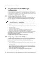
Configuring a Standalone Station ........................................................................ 46
Configuring an Associated Station....................................................................... 46
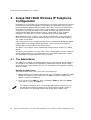
Avaya 3641/3645 Wireless IP Telephone Configuration .......................................48
4.1
4.2
4.3
The Admin Menu................................................................................................. 48
WPA2 Enterprise PEAP Certificate Enrollment and EAP-FAST Manual PAC
Provisioning ........................................................................................................ 65
Admin Menu Default Table .................................................................................. 68
Issue 4, November 2009
5
Contents
4.4
5.
Configuration (Config) Menu ................................................................................70
Software License and Protocol Management ....................................................... 74
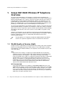
5.1
5.2
Minimum System Requirements ..........................................................................74
Minimum Configuration Process ..........................................................................75
6.
Avaya Communication Manager Integration Factors ............................................ 77
7.
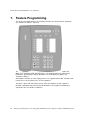
Feature Programming .......................................................................................... 80
7.1
7.2
Softkey Assignment .............................................................................................81
Function Assignment ...........................................................................................81
8.
Testing a Wireless IP Telephone.......................................................................... 83
9.
Diagnostic Tools................................................................................................... 84
9.1
9.2
9.3
10.
Certifying the Wireless IP Telephones.................................................................. 93
10.1
11.
Run Site Survey...................................................................................................84
Diagnostics Enabled ............................................................................................86
Syslog Mode........................................................................................................90
Conducting a Site Survey ....................................................................................93
Software Maintenance.......................................................................................... 95
11.1
Upgrading Wireless IP Telephones ......................................................................95
C.
Handset Administration Tool.................................................97
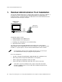
1.
Handset Administration Tool Installation............................................................... 98
1.1
1.2
2.
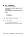
Using the Admin Tabs ........................................................................................ 104
2.1
2.2
2.3
2.4
2.5
2.6
2.7
2.8
2.9
3.
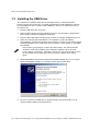
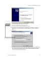
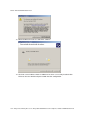
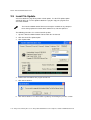
Installing the Handset Administration Tool............................................................99
Installing the USB Driver....................................................................................100
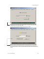
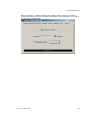
Connecting the Handset ....................................................................................104
Password Configuration.....................................................................................108
Character Table.................................................................................................108
Error Information................................................................................................109
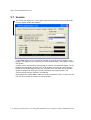
Software Updates ..............................................................................................110
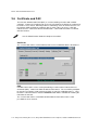
Certificate and PAC ...........................................................................................112
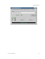
Version ..............................................................................................................114
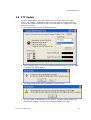
FTP Update .......................................................................................................115
Local File Update...............................................................................................116
Using the Settings Editor .................................................................................... 119
3.1
3.2
3.3
3.4
3.5
3.6
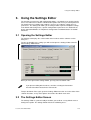
Opening the Settings Editor ...............................................................................119
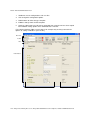
The Settings Editor Screen ................................................................................119
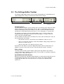
The Settings Editor Toolbar ...............................................................................121
Tab Options.......................................................................................................122
Creating Your Configuration Plan.......................................................................124
Regulatory Domain Mismatch ............................................................................128
D.
Appendices ........................................................................... 129
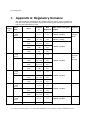
1.
Appendix A: Regulatory Domains....................................................................... 130
2.
Appendix B: Troubleshooting.............................................................................. 132
3.
Appendix C: Wireless IP Telephone Status Messages ....................................... 133
E.
Index...................................................................................... 149
6
Avaya Voice Priority Processor, Avaya 3641/3645 Wireless IP Telephone, Handset Administration Tool
A. Avaya Voice Priority Processor
AVPP
AVPP 20
AVPP 10
Installation, Configuration, and Administration
Issue 4, November 2009
7
Part A: Avaya Voice Priority Processor
1. Avaya Voice Priority Processor Overview
The Avaya Voice Priority Processor is an Ethernet LAN device that works with access
points (APs) to provide QoS on the wireless LAN. Voice packets to and from the Avaya
Wireless IP Telephones are intercepted by the Avaya Voice Priority Processor and
encapsulated for prioritization as they are routed to and from an IP telephony server.
1.1 Avaya Voice Priority Processor (AVPP), QoS and
Security
The Avaya Voice Priority Processor (AVPP) is an Ethernet LAN device that works with
the AP to provide quality of service QoS on the wireless LAN. Voice packets to and from
the Avaya 3641/3645 Wireless IP Telephones are intercepted by the Avaya Voice Priority
Processor and encapsulated for prioritization as they are routed to and from an IP
telephony server or gateway. This mechanism is fully compatible with the IEEE
802.11a/b/g standards.
The latest software versions are required to support the features described in
this document.
1.2 Avaya Voice Priority Processor Models
The AVPP is available in three models. Which model is selected for your facility depends
on current and expected capacity. All AVPPs within a subnet must be the same model
type.
•
AVPP 100 – Serves 80 calls simultaneously.
•
AVPP 20 – Serves 20 powered-on handsets.
•
AVPP 10 – Serves 10 powered-on handsets.
See the following capacity tables for multiple AVPP system capacities.
All AVPP models are installed, configured and administered according to the instructions
in this document. The model information is available on the Software Version screen. See
section 7.3 Software Version.
1.3 The Timing Function
Avaya Voice Priority Processors provide the connection or "gateway" to the IP PBX for
the Wireless IP Telephones and the "timing" function for active calls. This "gateway"
function is distributed across the AVPPs.
The number of active AVPPs is determined dynamically. Whenever AVPPs are added to
or removed from the system, the distribution of the "timing" function for active calls is
affected.
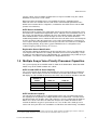
1.4 Multiple Avaya Voice Priority Processors
Multiple AVPP environments are those which have more than one Avaya Voice Priority
Processor. Up to four AVPP 10 models or up to two AVPP 20 models may be installed in
8
Avaya Voice Priority Processor, Avaya 3641/3645 Wireless IP Telephone, Handset Administration Tool
AVPP Overview
any one subnet. Up to 16 models of AVPP Servers may be installed in any one subnet.
All AVPPs must be in the same subnet.
When more than one AVPP Servers are installed, the wireless telephone load is
balanced across the available Servers, both for the communication path between the
AVPP Server and the wireless telephones, and between the AVPP Server and the PBX
(or other far-end device).
AVPP Server Availability
An Avaya handset registers to a single AVPP Server the first time it is powered on. Once
the handset has contacted this Registration Server, it obtains a list of all AVPP Servers in
the system. The handset then maintains this list in non-volatile memory and updates only
when rebooted. When a handset later attempts to check in and cannot contact the
ordained Registration Server, it will then fall back to its list of other Servers and attempt to
check in elsewhere. After the handset has successfully checked into the system once, it
never requires that the Registration Server be present unless the handset is reconfigured
back to factory defaults, or the entire system of AVPP Servers is changed out. See
section Swapping/Adding/Deleting SVP Servers.
Registration Server Identification
The handsets identify the AVPP Server in three possible ways. These are outlined in the
next chapter of this document. Essentially, the AVPP Server can be identified by a static
IP address in the Admin menu, by a DHCP option 151 specification, or by a DNS query of
“SLNKSVP2”. The address found identifies the Registration Server.
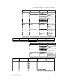
1.5 Multiple Avaya Voice Priority Processor Capacities
The system capacity of each AVPP model is shown in the below tables. Note that AVPP
models may not be combined within one subnet.
AVPP 10 and AVPP 20 Server Capacity
The system capacity of the AVPP 10 and AVPP 20 is measured by number of poweredon handsets. If this number exceeds the maximum, the handset that cannot be served
will display an error and will not connect to the AVPP. Other handsets will not be affected.
Number of handsets
Number of
AVPPs
AVPP 10
AVPP 20
1
2
3
4
10
20
30
40
20
40
NA
NA
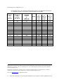
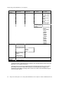
AVPP 100 Server Capacity
The capacity of the AVPP Server is determined by active calls. The table below shows
the capacity of an IP gateway in a multiple-AVPP Server environment. The table shows
the total possible calls at 100% active calls. However, since it is unlikely that all handsets
will be in use at the same time, the table then analyzes the number of handsets that
could be installed in any given system where 10%, 15% or 20% of the handsets are in
1
active calls at any one time. The calculations are not linear due to the Erlang calculation
1
An Erlang is a unit of telecommunications traffic measurement. Strictly speaking, an Erlang represents the continuous
use of one voice path. In practice, it is used to describe the total traffic volume of one hour.
Issue 4, November 2009
9
Part A: Avaya Voice Priority Processor
for telephony traffic. The possible installed handsets figures are approximate and meant
as a guideline and not as an absolute recommendation for any facility.
Number
of
AVPP
Servers
Number of
calls
possible
per Server
Total possible
installed
handsets
@
100% in
active calls
Possible installed handsets
Erlang
1
80
80
2
64
3
@
10% in
active
calls
@
15% in
active
calls
@
20% in
active
calls
65
500
433
325
128
111
1000
740
555
60
180
160
1500
1067
800
4
58
232
211
2000
1407
1055
5
57
285
262
2500
1747
1310
6
56
336
312
3000
2080
1560
7
56
392
367
3500
2447
1835
8
55
440
415
4000
2767
2075
9
55
495
469
4500
3127
2345
10
55
550
524
5000
3493
2620
11
55
605
578
5500
3853
2890
12
54
648
621
6000
4140
3105
13
54
702
674
6500
4493
3370
14
54
756
728
7000
4853
3640
15
54
810
782
7500
5213
3910
16
54
864
836
8000
5573
4180
Erlang traffic measurements are made in order to help telecommunications network designers understand traffic patterns
within their voice networks. This is essential if they are to successfully design their network topology and establish the
necessary trunk group sizes.
Erlang traffic measurements or estimates can be used to work out how many lines are required between a telephone
system and a central office (PSTN exchange lines), or between multiple network locations.
Please visit www.erlang.com for additional information.
10
Avaya Voice Priority Processor, Avaya 3641/3645 Wireless IP Telephone, Handset Administration Tool
AVPP Overview
1.6 Notes on System Configuration
In an IP system using subnets to differentiate telephony areas, each subnet must
have its own access points. Each subnet may require an AVPP to maintain voice
quality, but this depends on traffic volume and router capacity.
Multiple AVPP environments are those which have more than one AVPP.
AVPP models may not be combined within one subnet. More than one AVPP
model type may be used within a facility if installed on different subnets.
Wireless IP Telephones cannot roam with uninterrupted service between
subnets unless specific LAN components are present. Certain AP/Ethernet
switch combinations establish a layer-2 tunnel across subnets that enables the
handsets to roam. Without this capability, any call in progress will be dropped
when the user moves out of range and the handset must be power-cycled in
order to resume functionality in the new subnet area.
Please contact your service representative for detailed configuration information
when installing multiple AVPP models across several different subnets.
IP multicast addresses are used when the Avaya 3645 Wireless IP Telephone is
installed and PTT is enabled. PTT requires that multicasting be enabled on the
subnet used for the Avaya Wireless IP Telephones, AVPP, and Avaya
Communication Manager.
The Avaya Voice Priority Processor requires a Cat. 5 cable connection between
its network port and the Ethernet switch. The Avaya Voice Priority Processor
auto-negotiates to the type of port on the Ethernet switch and supports 10BaseT, 100Base-T, full-duplex and half-duplex port types.
Issue 4, November 2009
11
Part A: Avaya Voice Priority Processor
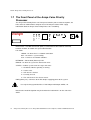
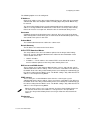
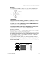
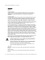
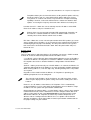
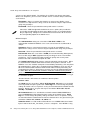
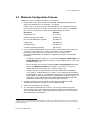
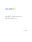
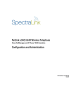
1.7 The Front Panel of the Avaya Voice Priority
Processor
The Avaya Voice Priority Processor’s front panel contains ports to connect to power, the
LAN, and to an administrative computer via an RS-232 port. Status LEDs supply
information about the Avaya Voice Priority Processor’s functioning.
1
L
N
K
O
K
A
C
T
C
O
L
NETWORK
E
R
R
O
R
2
3
4
5
Status
RS-232
RS-232 Port – male DB-9 connector (DTE) used for RS-232 connection to a terminal,
terminal emulator, or modem for system administration.
Link LEDs:
LNKOK – Lit when there is a network connection.
ACT – Lit if there is system activity.
COL – Lit if there are network collisions.
NETWORK – Port to wired (Ethernet) LAN.
ERROR – Lit when the system has detected an error.
STATUS – Indicate system error messages and status.
1 – Heartbeat, indicates gateway is running.
2 – If active calls.
3 – SVP Server is locked.
4 – Currently unused.
5 – This SVP Server is the cluster master.
PWR (power jack) – Connects to the AC adapter supplying power to the system.
Use only the Avaya-provided Class II AC Adapter with output 24VDC, 1A.
Note that the model designation may be found on the label which is on the side of the
AVPP.
12
Avaya Voice Priority Processor, Avaya 3641/3645 Wireless IP Telephone, Handset Administration Tool
PWR
Installing the AVPP
2. Installing the Avaya Voice Priority
Processor
As shown in the system diagram the Avaya Voice Priority Processor is connected to the
Ethernet switch. The specifications covered here allow for great flexibility in physical
placement of the components within stated guidelines.
See the Configuration and Administration for Avaya 3641/3645 Wireless IP Telephones
for information on IP addressing.
This unit must be installed by a service person familiar with the installation of electronic
equipment.
Do not power up the unit before it has been properly grounded to a protective earth. See
Grounding instructions below.
2.1 Required Materials
The following equipment must be provided by the customer.
1. Power Outlet – Must accept Avaya-provided AC adapter.
2. Backboard space – The Avaya Voice Priority Processor is designed to be wall
mounted to ¾" plywood securely screwed to the wall.
3. Screws – Required to mount the Avaya Voice Priority Processor to the wall. Four #8 ¾" panhead wood screws (or similar device) are required.
4. Cat. 5 Cable – RJ-45 connector at the Avaya Voice Priority Processor. Connection to
Ethernet switch.
2.2 Locate the Avaya Voice Priority Processor
The Avaya Voice Priority Processor measures approximately 4 x 12.5 x 7", and weighs
about five pounds. The unit can be wall mounted, vertically or horizontally, over ¾"
plywood. The AVPP can also be rack-mounted using a rack-mount kit (sold separately).
Locate the Avaya Voice Priority Processor in a space with:
1. Sufficient backboard mounting space (for wall mount) and proximity to the LAN
access device (switched Ethernet hub) and power source.
2. Easy access to the front panel, which is used for cabling.
3. A maximum distance of 325 feet (100 meters) from the Ethernet switch.
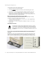
2.3 Install the Avaya Voice Priority Processor
The Avaya Voice Priority Processor may be mounted on a rack or to a wall.
Mount the AVPP on a rack
The rack-mount kit is designed for mounting equipment in a standard 19" rack and should
contain the following equipment:
1. Mounting plates – Two for each AVPP to be mounted.
2. Screws – Four rack-mount screws for each AVPP to be mounted.
Issue 4, November 2009
13
Part A: Avaya Voice Priority Processor
To rack-mount the Avaya Voice Priority Processor:
1. Remove the corner screws from the AVPP.
2. Screw the U-shaped end (round screw holes) of the two mounting plates to the
AVPP.
3. Screw the other end of the two mounting plates (oblong screw holes) to the rack.
4. Repeat steps 1-3 for each additional AVPP. The mounting plate is designed to
provide the correct minimum spacing between units. When mounting multiple units,
stack the units in the rack as closely as possible.
Mount the Avaya Voice Priority Processor to a wall
The Avaya Voice Priority Processor can be mounted either horizontally or vertically.
To mount the Avaya Voice Priority Processor to a wall:
1.
Using a 1/8" drill bit, drill four pilot holes, on 1.84" by 12.1" centers (approximately
equivalent to 1-13/16" by 12-1/8").
2. Insert the #8 x 3/4" screws in the pilot holes and tighten, leaving a 1/8" to 1/4" gap
from the wall.
Grounding Instructions
Safety
Warning
The metal chassis of this unit may contain leakage currents (i.e., "touch"
current) which is cumulative when multiple units are connected together to
form a system. To prevent the summation of leakage currents from being
present on exposed metal surfaces, the following installation procedure must
be followed.
All system units must be grounded to a protective earth by means of the grounding stud
located on the rear panel. Refer to the illustration below for recommended continuity
connection.
No more than 15 units may be grounded through one connection to the protective earth
ground. Systems involving more than 15 units must be broken up into groups of 15 or
fewer units with each group provided with an independent protective earthing conductor.
14
Avaya Voice Priority Processor, Avaya 3641/3645 Wireless IP Telephone, Handset Administration Tool
Installing the AVPP
Connect Avaya Voice Priority Processor to LAN
Using a Cat. 5 cable, connect the NETWORK port on the Avaya Voice Priority Processor
to the connecting port on the Ethernet switch.
Connect Power
1. Once the units have been properly grounded, connect the power plug from the AC
adapter to the jack labeled PWR on the AVPP Server.
Use only the Avaya-provided Class II AC Adapter with output 24VDC, 1A.
2. Plug the AC adapter into a wall outlet to apply power to the Avaya Voice Priority
Processor.
3. Verify that leakage current ("touch" current) is below 250 µA rms on exposed metal
surfaces.
4. If leakage is excessive, power off the system and re-verify ground path continuity.
5. The system will cycle through diagnostic testing and the LEDs will blink for about one
minute. When the system is ready for use:
•
The ERROR LED should be off.
•
Status 1 should be blinking.
Issue 4, November 2009
15
Part A: Avaya Voice Priority Processor
3. Configuring the Avaya Voice Priority
Processor
During initial setup of the Avaya Voice Priority Processor the IP address is established
and the maximum number of active calls per access point is set. Optionally, you may
enter a hostname and a location for software updates via TFTP.
3.1 Connecting to the Avaya Voice Priority Processor
The initial connection to the Avaya Voice Priority Processor must be made via a serial
connection to establish the Avaya Voice Priority Processor’s IP address. After the IP
address is established, connection to the Avaya Voice Priority Processor may be done
via the network using telnet. It is recommended that the basic setup actions occur while
the serial connection is made.
Connect via the Serial Port
1. Using a DB-9 female, null-modem cable, connect the Avaya Voice Priority Processor
to the serial port of a terminal or PC.
2. Run a terminal emulation program (such as HyperTerminal™) or use a VT-100
terminal with the following configuration –
Bits per second – 9600
Data bits – 8
Parity – None
Stop bits – 1
Flow control – None
3. Press Enter to display the Avaya Voice Priority Processor login screen.
4. Enter the default login – admin and default password – admin. These are case
sensitive.
5. The NetLink SVP-II System menu will display.
Connecting Via Telnet
Telnet can only be used after the Avaya Voice Priority Processor’s IP address is
configured.
The telnet method of connection is used for routine maintenance of the NetLink Server
for both local and remote administration, depending on your network.
To connect via telnet, run a telnet session to the IP address of the Avaya Voice Priority
Processor. Once you connect and log in, the NetLink SVP-II System menu displays.
16
Avaya Voice Priority Processor, Avaya 3641/3645 Wireless IP Telephone, Handset Administration Tool
Configuring the AVPP
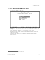
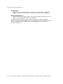
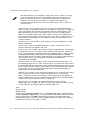
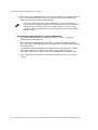
3.2 The NetLink SVP-II System Menu
The main menu displays as shown here:
System Status – Menu for viewing error messages, status of operation and software code
version.
2
SVP-II Configuration – Allows you to set the mode and reset the system.
Network Configuration – Allows you to set network configuration options, including IP
address and hostname.
Change Password – Allows you to change the password for Avaya Voice Priority
Processor access.
2
SVP-II is a designation used internally by Avaya Engineering.
Issue 4, November 2009
17
Part A: Avaya Voice Priority Processor
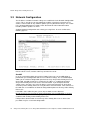
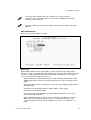
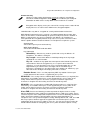
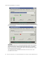
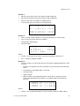
3.3 Network Configuration
The IP address and other network settings are-established via the Network Configuration
screen. This is also where you may optionally establish a hostname and enter the IP
address of the location of any software updates you may obtain from Avaya. See section
6, the Software Maintenance section, of this document for more information about
installing software updates via TFTP.
Scroll to Network Configuration and select by pressing Enter. A screen similar to the
following appears:
Note the navigation options at the bottom of the screen. Press Enter to change a value,
ESC to exit the screen, and the arrow keys to move the cursor.
SendAll
In an IP system with multiple Avaya Voice Priority Processors, the SendAll option is
provided to speed configuration and to ensure identical settings. The S–SendAll option
allows you to send that configuration parameter to every Avaya Voice Priority Processor
on the LAN. SendAll can only be used after the IP address is established on EACH
Avaya Voice Priority Processor via the serial connection. If you anticipate identical
settings across the LAN, set just the IP address and custom hostname (if desired) for
each Avaya Voice Priority Processor using the initial serial connection. Then connect via
the LAN and use SendAll to set identical configuration options for all Avaya Voice Priority
Processors.
If SendAll is to be utilized in your system, all passwords must be identical.
Do not change the password at the initial configuration if the SendAll option is desired.
Use the default password and change it globally if desired after a LAN connection is
established for all Avaya Voice Priority Processors.
If independent administration of each Avaya Voice Priority Processor is desired, the
passwords may be set at initial configuration.
18
Avaya Voice Priority Processor, Avaya 3641/3645 Wireless IP Telephone, Handset Administration Tool
Configuring the AVPP
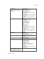
The following options must be configured:
IP Address
Enter the IP address of the Avaya Voice Priority Processor, defined by your network
administrator. Enter the complete address including digits and periods. DHCP may
be entered.
The Avaya Voice Priority Processor will automatically lock for maintenance if the IP
address is changed. When this Maintenance Lock occurs, the Avaya Voice Priority
Processor must be reset upon exit. All active calls are terminated during a reset.
Hostname
(Optional) change the default host name, if desired. This is the name of the Avaya
Voice Priority Processor to which you are connected, for identification purposes only.
You cannot enter spaces in this field.
Subnet Mask
The network administrator must define the subnet mask.
Default Gateway
The IP address of a router on the local subnet.
SVP-II TFTP Download Master
This entry indicates the source of software updates for the Avaya Voice Priority
Processor. See the Software Maintenance section for more information. Valid
source location entries are:
•
NONE – disables.
•
IP Address – The IP address of a network TFTP server that will be used to
transfer software updates to the Avaya Voice Priority Processor.
DNS server and DNS domain
These settings are used to configure Domain Name services. Consult your system
administrator for the correct settings. These can also be set to DHCP. This will cause
the DHCP client in the Avaya Voice Priority Processor to attempt to automatically get
the correct setting from the DHCP server. The DHCP setting is only valid when the IP
address is also acquired using DHCP.
WINS servers
These setting are used for Windows Name Services. Consult your system
administrator for the correct settings. These can also be set to DHCP. This will cause
the DHCP client in the Avaya Voice Priority Processor to attempt to automatically get
the correct setting from the DHCP server. The DHCP setting is only valid when the IP
address is also acquired using DHCP.
When the name services are set up correctly, the Avaya Voice Priority Processor
can translate hostnames to IP addresses. Using telnet, it is also possible to
access the Avaya Voice Priority Processor using its hostname instead of the IP
address.
Workgroup
As set in WINS.
Issue 4, November 2009
19
Part A: Avaya Voice Priority Processor
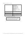
Syslog Server
Logging may be set to either DHCP (see DNS above), an [IP address] or NONE. If
Syslog is set, a message is sent to the syslog server when an alarm is triggered.
Disable Telnet Service
Prevents Telnet access into the AVPP. Reset the AVPP for the change to take effect.
Upon reset the Telnet protocol server is not started.
The Avaya Voice Priority Processor must be reset in order to set the configuration
options. If the Avaya Voice Priority Processor is in Maintenance Lock, you must manually
reset it by selecting the Reset option in the SVP-II Configuration screen and then
pressing Y upon exit.
20
Avaya Voice Priority Processor, Avaya 3641/3645 Wireless IP Telephone, Handset Administration Tool
Configuring the AVPP
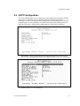
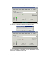
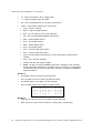
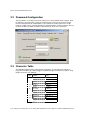
3.4 AVPP Configuration
The SVP-II Configuration screen is where you set the mode of the Avaya Voice Priority
Processor. It is also where you can lock the Avaya Voice Priority Processor for
maintenance and reset the Avaya Voice Priority Processor after maintenance. The type
of gateway you are using determines the mode of the Avaya Voice Priority Processor.
From the main menu, scroll to SVP-II Configuration and select by pressing Enter.
SVP-II Mode – Defaults to NetLink IP for an IP environment. Press enter to select
and the screen is immediately redrawn with additional options for the IP environment.
The following options must be configured:
Issue 4, November 2009
21
Part A: Avaya Voice Priority Processor
Phones per Access Point – Access point specifications are detailed in the
Configuration Notes for each brand and type. Refer to these notes when entering
the number of simultaneous calls supported for your type.
802.11 Rate – Select 1MB/2MB to limit the transmission rate between the Wireless IP
Telephones and access points. Select Automatic to allow the Wireless IP Telephone
to determine its rate.
First Alias IP Address/Last Alias IP Address – Alias IP Addresses are not necessary
in Avaya systems.
Enable H.323 Gatekeeper – In certain H.323 protocol systems, the AVPP may
function as a gatekeeper. Enter Y to have the AVPP function as the gatekeeper in the
H.323 protocol environment.
Ethernet link – The AVPP will auto-negotiate unless there is a need to specify a link
speed.
Check-in throttling – The check-in throttling option regulates the number of handsets
that can check-in simultaneously. The error Maximum payloads reached is caused by
a massive check-in that has overwhelmed the server. If persisting, throttling may be
raised. However, a setting that is too high may slow check-in performance. The
option allows for a setting from 0 to 4, with 0 being the least amount of throttling and
4 being the most. Consult with Customer Support for help in determining if throttling
is advised for your system.
Missed ding limit– The Missed ding limit defaults to 3 and should be left at this setting
unless advised by Customer Service to raise or lower it. The DING message is a
proprietary method of communication between system elements. This setting is
designed to assist service engineers in fine-tuning system performance and should
not be changed without their consultation.
Load balancing enables a locked SVP Server to distribute idle handsets to other
SVP Servers in the cluster. Existing calls will not be interrupted and the SVP
Server will become idle once all calls are ended and idle phones are transferred
to another SVP Server.
System Locked – This option is used to take the system down for maintenance. The
default entry is N (No). Set it at Y (Yes) to prevent any new calls from starting. Return
to N to restore normal operation.
Maintenance Lock – The system automatically sets this option to Y (Yes) after certain
maintenance activities that require reset, such as changing the IP address.
Maintenance Lock prevents any new calls from starting. Note that the administrator
cannot change this option. It is automatically set by the system. Reset the system at
exit to clear Maintenance Lock.
Inactivity Timeout (min) – Set the number of minutes the administrative module can
be left unattended before the system closes it. This number can be from 1 to 100. If it
is set to zero (0), the administrative module will not close due to inactivity.
QoS Configuration – Select this option to set the DSCP tags. See QoS
Configuration section below.
Reset System – If this option is selected, you will be prompted to reset the Avaya
Voice Priority Processor upon exiting this screen.
Reset All SVP Servers – If this option is selected, you will be prompted to reset all
AVPPs upon exiting this screen. This is necessary if you have changed
configurations on other AVPPs by using the SendAll option.
22
Avaya Voice Priority Processor, Avaya 3641/3645 Wireless IP Telephone, Handset Administration Tool
Configuring the AVPP
The Avaya Voice Priority Processor should be reset at the end of any
maintenance procedure that requires a reset either via Maintenance Lock or
manually via Reset System.
Note that resetting the Avaya Voice Priority Processor will terminate any calls in
progress.
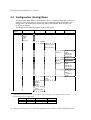
QoS Configuration
DSCP tags set packet priorities for QoS.
DSCP Tag
DSCP (Differentiated Services Code Point) is a QoS mechanism for setting relative
priorities. Packets are tagged with a DSCP field in the IP header. The decimal value may
be set as a number from 0-63 and may be different for each traffic class listed on the
screen. The default for all traffic classes is 4.
Administration tags set the priority for telnet, TFTP, and other administrative traffic.
Administrative traffic can have the lowest priority because it does not require voice
quality.
WT (In call) traffic requires voice quality and may be set to a higher priority than WT
(Standby) traffic.
RTP traffic is the audio traffic to the IP PBX. It requires voice quality.
PBX traffic is not audio to the PBX.
Inter-SVP2 traffic is the information-passing protocol that AVPP Servers use to
communicate with each other.
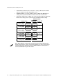
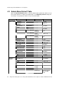
When forwarding packets, the AVPP Server shall always overwrite the received
DSCP value. The final DSCP tag for packets in each of the traffic classes are
assigned a DSCP value based on the following rules. (Please see table on next
page.)
Issue 4, November 2009
23
Part A: Avaya Voice Priority Processor
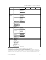
•
If both Administration and the Traffic Class setting is Default, the Default
value as shown in the table below will be used.
•
If Administration is set at any number (Value X) other than Default, that
setting (Value X) it will override the Default value of the Traffic Class.
•
If any of the Traffic Class settings are set at any value (Value Y) other than
Default, that setting (Value Y) will override the Administration setting.
Administration
Traffic Class
WT (In call)
Priority High
WT (Standby)
Priority Med
RTP
Priority High
PBX
Priority Med
Inter-SVP2
Priority Med
Administration
Priority Low
24
Default
Value X
Default
4
X
Value Y
Y
Y
Default
0
X
Value Y
Y
Y
Default
4
X
Value Y
Y
Y
Default
0
X
Value Y
Y
Y
Default
0
X
Value Y
Y
Y
Default
0
X
Value Y
Y
Y
Note: Default DSCP settings will mark traffic for Best Effort handling under
normal circumstances. Please consider changing these values based on the
recommended QoS settings from your network hardware manufacturer to
achieve prioritization for your voice traffic.
Avaya Voice Priority Processor, Avaya 3641/3645 Wireless IP Telephone, Handset Administration Tool
Configuring the AVPP
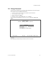
3.5 Change Password
If desired, the password to access the Avaya Voice Priority Processor may be changed.
A password must meet the following requirements:
1. It must be more than four characters, but cannot exceed 16 characters.
2. The first character must be a letter.
3. Numbers or letters are allowed.
4. No dashes, spaces, or punctuation marks, etc. are allowed.
Select Change Password from the main menu. A screen similar to the following will
appear:
Enter the information and either select Set Password or press the S key to set the new
password.
If you forget a password, call Avaya Customer Service for assistance.
Issue 4, November 2009
25
Part A: Avaya Voice Priority Processor
4. Swapping/Adding/Deleting AVPPs
Whenever an AVPP is removed from the system, Wireless IP Telephones that are using
the AVPP will be affected and calls may be lost. If the removal of the AVPP is intentional,
the administrator should lock and idle the system prior to removing an AVPP.
Load balancing enables a locked AVPP Server to distribute idle handsets to
other AVPP Servers in the cluster. Existing calls will not be interrupted and the
AVPP Server will become idle once all calls are ended and idle phones are
transferred to another AVPP Server.
Adding an AVPP
A new AVPP is detected within two seconds of being added to the system
(booted/configured/connected). When detected, any Wireless IP Telephone not active in
a call will eventually be forced to reboot and check in again. Any Wireless IP Telephone
in a call will immediately switch to the AVPP that should provide its "timing" function. This
switch should not be noticeable to the user since it is similar to a normal handoff between
access points. When the Wireless IP Telephone ends the call, it will eventually be forced
to reboot and check in again. Only a few handsets at a time are rebooted to prevent
excessive check in traffic on the network. Handsets scheduled to be rebooted can still
make calls and will be rescheduled for reboot when the call is ended.
Removing an AVPP
The preferred method for removing an AVPP Server from an active system is to first lock
the AVPP Server. When an AVPP Server is locked for removal from the system, load
balancing enables the locked AVPP Server to distribute idle handsets to other AVPP
Servers in the cluster. Active calls will not be interrupted. The locked AVPP Server will
become idle once all calls are ended and idle handsets are registered to other AVPP
Servers. Once all handsets have been moved---as evidenced by the number of
Telephones in Use on the Network Status screen---the idle AVPP Server may be
unplugged and removed from the system.
During this process, there is a short period where a handset registered on a locked AVPP
Server may attempt to initiate a call before it is re-registered to another AVPP Serveron a
locked AVPP Server. In this case, if there is an unlocked AVPP Server in the cluster, the
AVPP Server will tell the handset to reboot. As it reboots, the handset will check-in with
an available AVPP Server and the user may then start a call. Handsets registered on
unlocked AVPP Servers are not affected.
Of course if a system only has one AVPP Server, no calls will be possible until the
removed AVPP Server is replaced.
AVPP Server failure
If an AVPP Server becomes unable to manage calls or fails, any handset in an active call
using registered to that AVPP Server loses service (and any calls) and will reboot within
30 seconds. will lose the call. However, upon initiating a new call, the handset will locate
another Server and will be able to make new calls. After rebooting, the handset will
register with another AVPP (if there is one available) and be able to make new calls.
Handsets not registered on the failed AVPP may experience a few seconds of disruption
in audio but are otherwise unaffected.
26
Avaya Voice Priority Processor, Avaya 3641/3645 Wireless IP Telephone, Handset Administration Tool
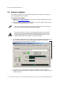
Software Maintenance
5. Software Maintenance
The Avaya Voice Priority Processor uses proprietary software programs written and
maintained by Avaya Corporation. The software versions that are running on the system
components can be displayed via the System Status screen.
You may obtain information about software updates from Avaya or its authorized dealer.
At startup the Avaya Voice Priority Processor uses TFTP to check the software version it
is running against the version in the TFTP location. If there is a discrepancy, the Avaya
Voice Priority Processor will download the version in the TFTP location.
Software Updates
Lock the Avaya Voice Priority Processor in the SVP-II Configuration screen prior to
updating the software. In multiple AVPP Server systems, all AVPP Servers must be
locked and upgraded at the same time.
Downloads for the Avaya Voice Priority Processor are available from your service
representative.
After software updates are obtained from Avaya, they must be transferred to the TFTP
location in the LAN to update the code used by the Avaya Voice Priority Processor(s).
Note that locking the Avaya Voice Priority Processor will prevent new calls from
starting. All calls in progress will be terminated when the Avaya Voice Priority
Processor is reset.
Issue 4, November 2009
27
Part A: Avaya Voice Priority Processor
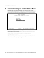
6. Troubleshooting via System Status Menu
Information about system alarms, and network status displays on various screens
accessed through the System Status Menu screen, which is opened from the main menu
of the Avaya Voice Priority Processor. See the previous sections for directions on how to
connect to the Avaya Voice Priority Processor and navigate to the System Status Menu.
Error Status – Displays alarm and error message information.
Network Status – Displays information about the Ethernet network to which the Avaya
Voice Priority Processor is connected.
Software Versions – Lists the software version for each Avaya component.
Gatekeeper Database – not used.
Options on the System Status menu provide a window into the real time operation of the
components of the system. Use this data to determine system function and to
troubleshoot areas that may be experiencing trouble.
28
Avaya Voice Priority Processor, Avaya 3641/3645 Wireless IP Telephone, Handset Administration Tool
Troubleshooting via System Status Menu
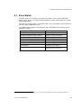
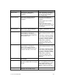
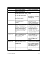
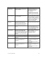
6.1 Error Status
The Error Status screen displays any alarms that indicate some system malfunction.
Some of these alarms are easily remedied and others require a call to Avaya’s Customer
Support Department.
From the System Status Menu, select Error Status. The screen displays active alarms on
the Avaya Voice Priority Processor.
The following table displays the list of alarms and a description of the action to take to
eliminate the alarm.
Alarm Text
Action
Maximum payload usage reached
Reduce usage, clear alarm
Maximum telephone usage reached
Reduce usage, clear alarm
3
Maximum access point usage reached
Reduce usage, clear alarm
Maximum call usage reached
Reduce usage, clear alarm
SRP audio delayed
Reduce usage, clear alarm
SRP audio lost
Reduce usage, clear alarm
No IP address
Configure an IP address
AVPP Server(s) lost
Reduce usage or replace lost
AVPP Server. Clear alarm
Press C to clear all clearable alarms.
3
If capacity problems persist, additional AVPP servers may need to be added to the system to improve performance.
Issue 4, November 2009
29
Part A: Avaya Voice Priority Processor
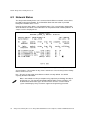
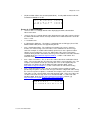
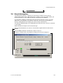
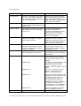
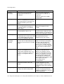
6.2 Network Status
The Avaya Voice Priority Processor is connected to the Ethernet network, referred to as
the LAN or Local Area Network. The information about that connection is provided
through the Network Status screen.
From the System Status Menu, select Network Status. The screen displays information
about the Ethernet network. This information can help troubleshoot network problems. A
sample screen is displayed here.
Ethernet Address – MAC address of the Avaya Voice Priority Processor (hexadecimal).
System Uptime – The number of days, hours and minutes since the Avaya Voice Priority
Processor was last reset.
Net – The type of connection to the Ethernet switch currently utilized. See AVPP
Capacity for more information.
30
Data is transmitted over Avaya components by proprietary technology developed
by Polycom, Inc. The SpectraLink Radio Protocol (SRP) packets and bytes can
be differentiated from other types of transmissions and are used to evaluate
system functioning by Avaya customer support and engineering personnel.
Avaya Voice Priority Processor, Avaya 3641/3645 Wireless IP Telephone, Handset Administration Tool
Troubleshooting via System Status Menu
RX – Ethernet statistics concerning the received packets during System Uptime.
bytes – bytes received
packets – packets received
errors – Sum of all receive errors (long packet, short packet, CRC, overrun,
alignment)
drop – packets dropped due to insufficient memory
fifo – overrun occurred during reception
alignment – nonoctet-aligned packets (number of bits NOT divisible by eight)
multicast – packets received with a broadcast or multicast destination address
TX – Ethernet statistics concerning the transmitted packets during System Uptime.
bytes – bytes transmitted
packets – packets transmitted
errors – Sum of all transmit errors (heartbeat, late collision, repeated collision,
underrun, carrier)
drop – packets dropped due to insufficient memory
fifo – underrun occurred during transmission
carrier – carrier lost during transmission
collisions – packets deferred (delayed) due to collision
SVP-II Access Points in Use – Access points in use by Wireless IP Telephones, either in
standby or in a call. ‘Last’ is current, ‘Max’ is the maximum number in use at one time.
SVP-II Access Points in Calls – Access points with Wireless IP Telephones in a call.
SVP-II Telephones in Use – Wireless IP Telephones in standby or in a call.
SVP-II Telephones in Calls – Wireless IP Telephones in a call.
SVP-II SRP Audio (Delay) – SRP audio packets whose transmission was momentarily
delayed.
SVP-II SRP Audio (Lost) – SRP audio packets dropped due to insufficient memory
resources.
Issue 4, November 2009
31
Part A: Avaya Voice Priority Processor
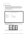
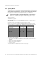
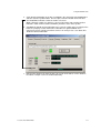
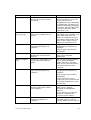
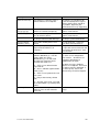
6.3 Software Version
The Avaya Voice Priority Processor and Wireless IP Telephones utilize Avaya’s
proprietary software that is controlled and maintained through versioning. The Software
Version screen provides information about the version currently running on the Avaya
Voice Priority Processor. This information will help you determine if you are running the
most recent version and will assist Avaya engineering and/or customer support in
troubleshooting software problems.
This screen also displays the model type.
From the System Status Menu, select Software Version. A sample screen is displayed
here.
Note that the software versions on your system may be different from the versions
displayed in the above sample screen.
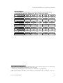
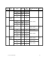
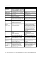
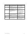
The table below shows the description, major version numbers, and filenames of the files
that are provided when downloading updates.
Name
Major
version
number
Filenam
e
Table of
contents
173
svp100.t
oc
Functional
code
174
zvmlinu
x
File system
175
flashfs
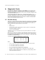
The minor version numbers for these three files must all match, as they do in the screen
example (17x.024).
32
Avaya Voice Priority Processor, Avaya 3641/3645 Wireless IP Telephone, Handset Administration Tool
B. Avaya 3641/3645 Wireless IP Telephones
Configuration and Administration
Issue 4, November 2009
33
Part B: Avaya 3641/3645 Wireless IP Telephone
1. Avaya 3641/3645 Wireless IP Telephone
Overview
The Avaya 3641/3645 Wireless IP Telephone is a Wi-Fi handset for workplace IP
telephone systems. The Wireless IP Telephone operates over an 802.11a/b/g/n wireless
Ethernet LAN providing users a wireless voice over IP (VoIP) extension. By seamlessly
integrating with an Avaya Communication Manager, Wireless IP Telephone users are
provided with high-quality mobile voice communications throughout the workplace. The
Wireless IP Telephone gives users the freedom to roam throughout the workplace while
providing users with all the features and functionality of an IP desk phone.
The Avaya 3641/3645 Wireless IP Telephone provides a wireless extension to the Avaya
Communication Manager. The Wireless IP Telephones reside on the wireless LAN with
other wireless devices using direct-sequence spread spectrum (DSSS) radio technology.
The handset radio transmits and receives packets at up to 54Mb/s using 802.11a/b/g
technology.
A Wireless IP Telephone must be administered on the Avaya Communication Manager
for the specific features and lines to be accessed by the Wireless IP Telephone. After the
handset is registered, it receives its configuration information from the Avaya
Communication Manager.
The latest Wireless IP Telephone and Handset Administration Tool software
versions are required to support the features described in this document.
1.1 WLAN Quality of Service (QoS)
Quality of Service is provided by using SpectraLink Voice Priority (SVP), Wi-Fi Standard
QoS or Cisco Compatible Extensions (CCX) version 4. These QoS modes can not be
mixed within the same WLAN; all Wireless IP Telephones on the network must have the
same QoS setting.
SVP
SpectraLink Voice Priority is a proprietary method of WLAN QoS, developed by
Polycom, to ensure enterprise-grade voice quality, battery life and call capacity for
SpectraLink Wireless IP Telephones. SVP requires the Avaya Voice Priority
Processor (AVPP) Server, which is an Ethernet LAN device that works in conjunction
with Wi-Fi APs to ensure QoS over the WLAN. Voice packets to and from the
Wireless IP Telephones are forwarded through the AVPP Server to ensure voice
prioritization as they are routed between the handset and an IP telephony server.
See the SpectraLink SVP Server: Administration Guide within IP Environments
document for detailed information about this device.
Wi-Fi Standard QoS
Avaya 3641/3645 Wireless IP Telephone support WMM, WMM Power Save and
WMM Admission Control - all QoS standards from the Wi-Fi Alliance based on IEEE
802.11e. The combination of these three standards provides enterprise-class QoS in
terms of voice quality, battery life and call capacity. The WLAN must also support
and enable each of these QoS mechanisms in order to ensure they are utilized. This
option does not require the AVPP Server.
34
Avaya Voice Priority Processor, Avaya 3641/3645 Wireless IP Telephone, Handset Administration Tool
Avaya 3641/3645 Wireless IP Telephone Overview
CCXv4
The CCX program allows WLAN client devices operating on Cisco APs to take
advantage of Cisco-specific features. When the CCXv4 operating mode is selected
on the handset, it operates using the required set of Cisco-specific and industry
standard QoS mechanisms. This option does not require the AVPP Server.
1.2 Security
The following security methods are supported by the handset.
WPA2 Enterprise
The handset supports WPA2 Enterprise, as defined by the Wi-Fi Alliance. WPA2,
which is based on the 802.11i standard, provides government-grade security by
implementing the Advanced Encryption Standard (AES) algorithm. The Enterprise
version of WPA2 uses 802.1X authentication, which is a port-based network access
control mechanism using dynamic encryption keys to protect data privacy. Two
802.1X authentication methods are supported on the Wireless IP Telephone, EAPFAST and PEAPv0/MSCHAPv2. Both of these methods require a RADIUS
authentication server to be available on the network and accessible to the phone.
Additional details are provided in Section 3.1.
Normal 802.1X authentication requires the client to renegotiate its key with the
authentication server on every AP handoff, which is a time-consuming process that
negatively affects time-sensitive applications such as voice. Fast AP handoff
methods allow for the part of the key derived from the server to be cached in the
wireless network, thereby shortening the time to renegotiate a secure handoff. The
Wireless IP Telephone supports two fast AP handoff techniques: Cisco Client Key
Management (CCKM) (only available on Cisco APs) and Opportunistic Key Caching
(OKC). One of these methods must be configured for support on the WLAN to
ensure proper performance of the handset.
WPA and WPA2 Personal
The handset supports WPA and WPA2 Personal, as defined by the Wi-Fi Alliance.
WPA2, which is based on the 802.11i standard, provides government-grade security
by implementing the Advanced Encryption Standard (AES) algorithm. WPA, which is
based on a draft version of the 802.11i standard before it was ratified, uses Temporal
Key Integrity Protocol (TKIP) encryption. The Personal version uses an
authentication technique called Pre-Shared Key (PSK) that allows the use of
manually entered keys to initiate security.
Cisco Fast Secure Roaming
Cisco’s Fast Secure Roaming (FSR) mechanism uses a combination of standardsbased and proprietary security components including Cisco Client Key Management
(CCKM), LEAP authentication, Michael message integrity check (MIC) and Temporal
Key Integrity Protocol (TKIP). FSR provides strong security measures for
authentication, privacy and data integrity on Cisco APs.
WEP
The handset supports Wired Equivalent Privacy (WEP) with both 40-bit and 128-bit
encryption.
Issue 4, November 2009
35
Part B: Avaya 3641/3645 Wireless IP Telephone
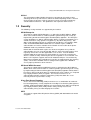
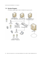
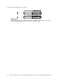
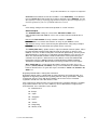
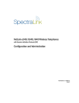
1.3 System Diagram
The following simplified diagram shows the components of a typical system.
36
Avaya Voice Priority Processor, Avaya 3641/3645 Wireless IP Telephone, Handset Administration Tool
Avaya 3641/3645 Wireless IP Telephone Overview
1.4 System Components
Avaya 3641/3645 Wireless IP Telephone
The Avaya 3641 Wireless IP Telephone is a lightweight, durable handset specifically
designed for mobile workplace use. The Avaya 3645 Wireless IP Telephone has the
same features and function, but in a more durable design and includes push-to-talk or
emergency call capability.
Handset telephony features are provided by emulating the Avaya 4612 IP Telephone.
Like a wired desk phone, the handset can receive calls directly, receive transferred calls,
transfer calls to other extensions, and make outside and long distance calls. The
Wireless IP Telephones can only be used on-premises within the WLAN coverage area.
AVPP Server (used with SpectraLink Voice Priority QoS method)
As described in Section 1.1, the AVPP Server is a wired LAN device that is required
when using SpectraLink Voice Priority for QoS.
Wi-Fi Access Points (APs)
Enterprise-grade Wi-Fi access points provide the connection between the wired LAN and
the wireless client device. 802.11a/b/g/n APs must be positioned in all areas where
Wireless IP Telephones will be used to ensure seamless radio coverage. The number,
type and placement of access points will affect the coverage area and capacity of the
wireless system. Careful planning of the WLAN is necessary to ensure good voice
quality. See the Best Practices Guide for Deploying SpectraLink 8020/8030 Wireless
Telephones for additional guidance.
Access points may use SpectraLink Voice Priority (SVP) in conjunction with an AVPP
Server, CCXv4 (Cisco APs only) or Wi-Fi Standard QoS (including WMM, WMM Power
Save and WMM Admission Control). APs must be properly configured to support the
corresponding QoS and security methods selected for the handset.
Ethernet Switch
One or more Ethernet switches interconnect multiple wired devices, including the AVPP
Server (if used for QoS), the Avaya IP telephony system, Avaya IP phones, TFTP Server,
RADIUS authentication server and WLAN access points. Enterprise Ethernet switches
provide the highest performance networks, which can handle combined voice and data
traffic, and are required when using the Wireless IP Telephones.
Although a single Ethernet switch network is recommended, the Wireless IP Telephones
and the AVPP Server can operate in larger, more complex networks, including networks
with multiple Ethernet switches, routers, VLANs, and/or multiple subnets, as long as the
AVPP Server and handsets are on the same subnet. However, in such networks, it is
possible for the quality of service (QoS) features of the AVPP Server to be compromised,
and consequently voice quality may suffer. Any network that consists of more than a
single Ethernet switch should be thoroughly tested to ensure any quality issues are
addressed. See the Best Practices Guide for Deploying SpectraLink 8020/8030 Wireless
Telephones for additional guidance.
Ensure that all your APs are attached to the same subnet for proper operation. The
handset can change subnets if DHCP is enabled and the handset is powered off then
back on when within range of APs on the new subnet. Note that the wireless telephones
cannot “roam” across subnets, since they cannot change IP addresses while operational.
Issue 4, November 2009
37
Part B: Avaya 3641/3645 Wireless IP Telephone
TFTP (Trivial File Transfer Protocol) Server
A TFTP server is required in the system to distribute software to the Wireless IP
Telephones and AVPP Server. It may be on a different subnet than the supported Avaya
IP telephony device(s) and APs.
NTP (Network Time Protocol) Server
An NTP server is optional except when using WPA2 Enterprise.
If WPA2 Enterprise security with PEAP authentication is used, the handset will validate
the PEAP certificate has a valid date and time. If the ACM call server specifies the
current time to be used by the handset, that time will be used for PEAP certificate
validation. If an NTP server is also present in the system, the handset will use the NTP
time for validation until handset time is overwritten by the ACM. If an NTP Server is not
available, the certificate will be deemed valid and operate accordingly.
Authentication Server (if using WPA2 Enterprise)
A RADIUS authentication server must be used to provide username/password based
authentication using RSA certificates for PEAPv0/MSCHAPv2 or PAC files for EAPFAST.
38
Avaya Voice Priority Processor, Avaya 3641/3645 Wireless IP Telephone, Handset Administration Tool
The Avaya 3641/3645 Wireless IP Telephone Specifications
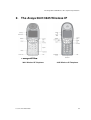
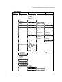
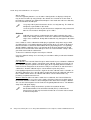
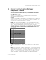
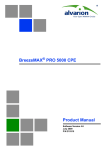
2. The Avaya 3641/3645 Wireless IP
Telephones
3641 Wireless IP Telephone
Issue 4, November 2009
3645 Wireless IP Telephone
39
Part B: Avaya 3641/3645 Wireless IP Telephone
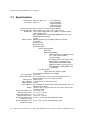
2.1 Specifications
Radio mode
(selectable)
Transmission type
Transmit data rate
WLAN QoS
WLAN security
FCC certification
Other certifications
Management
Voice encoding
VoIP Protocols
Transmit power
Display
Avaya 3641 Wireless IP
Telephone dimensions
Avaya 3645 Wireless IP
Telephone dimensions
Avaya 3641 Wireless IP
Telephone weight
Avaya 3645 Wireless IP
Telephone weight
40
(802.11b, 802.11g)
(802.11a)
2.4–2.4835 GHz
5.150–5.250 GHz
5.250–5.350 GHz
5.470–5.725 GHz
5.725–5.825 GHz
Direct-sequence spread spectrum (DSSS)
up to 54 Mb/s (802.11a/g), up to 11 Mb/s (802.11b)
Avaya Voice Priority Processor (AVPP) using SpectraLink
Voice Priority (SVP)
Wi-Fi Standard QoS (using WMM, WMM-Power Save and
WMM-Admission Control)
CCXv4
Wired Equivalent Privacy (WEP), 40-bit and 128-bit;
Cisco FSR
WPA Personal
WPA2 Personal
WPA2 Enterprise:
802.1X Authentication
EAP-FAST
PEAPv0/MSCHAPv2
PEAP certificate sizes in DER format:
512*, 1024*, 2048, 4096 bit
(*recommended)
Encryption Ciphers: AES, RSA, RC4
Data Integrity: Hashed Message
Authentication Code MD5 (HMACMD5) (RFC 2403, 2104) and Secure
Hash Algorithm-1 SHA (HMAC-SHA1) (RFC2404)
Fast AP Handoff
Opportunistic Key Caching (OKC)
Cisco Client Key Management (CCKM)
Part 15.247
IP 53 certified for resistance to dust and liquid resistance
MIL 810F Proc IV 516.5 for shock resistance
DHCP, TFTP
G.711µ-law, G.711a-law and G.729
CCMS
Up to 100mW Transmit Power Control (formerly 802.11h), see
Appendix A for details.
Up to five lines of text plus two icon status rows and one row
for softkey labels.
5.4" x 2.0" x 0.9"
(13.7 x 5.1 x 2.3 cm)
5.7" x 2.0" x 0.9"
(14.5 x 5.1 x 2.3 cm)
3.9 oz. ( 110.6 g) with Standard Battery Pack
4.2 oz. (119.1 g) with Standard Battery Pack
Avaya Voice Priority Processor, Avaya 3641/3645 Wireless IP Telephone, Handset Administration Tool
The Avaya 3641/3645 Wireless IP Telephone Specifications
Standard Battery Pack capacity
Extended Battery Pack capacity
Ultra-Extended Battery Pack
capacity
Issue 4, November 2009
4 hours talk, 80 hours standby
6 hours talk, 120 hours standby
8 hours talk, 160 hours standby
41
Part B: Avaya 3641/3645 Wireless IP Telephone
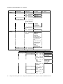
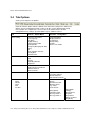
2.2 Handset Display
Display information provided by the Avaya Communication Manager when the Wireless
IP Telephone is off-hook will be passed directly to the Wireless IP Telephone display in
an emulation of the Avaya 4612 IP Telephone display handling. Certain characters may
be used by the Avaya Communication Manager that are not implemented in the Wireless
IP Telephone such as definable and special characters.
There are 12 programmable keys that may be allocated to line appearances or features
in any combination. Pressing the LINE key from the active mode displays the list of line
appearances extracted from the programmable keys list. The line appearances are also
mapped to corresponding line icons across the top of the Wireless IP Telephone display.
Press the FCN key while off-hook to scroll through system features. In this mode, the
display has four lines and up to 18 characters. OAI features, if assigned, will be displayed
with their shortcuts. The programmable key items that appear on this list each have a
state indicator in the second column of the display that shows a plus sign if the
associated feature is active. This second column is blank if the associated feature is not
active. The plus sign emulates a lit or blinking LED on an Avaya 4612 IP Telephone,
indicating an active feature. Press the shortcut key to activate the feature. Softkeys are
programmed to the fixed feature keys of the Avaya 4612 IP Telephone.
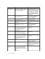
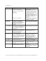
Indicator
Function
The signal-strength icon indicates the strength of the signal and can assist
the user in determining if the handset is moving out of range.
The voicemail icon is activated when a new voicemail message is received
if the feature is supported by the phone emulation.
The battery icon indicates the amount of charge remaining in the Battery
Pack. When only one level remains, the Battery Pack needs to be charged.
The speakerphone icon displays when the speakerphone is active.
1▪▪▪▪▪▪▪
The line indicators are associated with telephone line status and access.
Up and down arrows are displayed when the menu has additional options
above or below.
Left or right arrows are displayed during editing when the cursor may be
moved left or right.
PBX ring icon. A regular telephone call is coming in.
OAI ring icon. A call is coming in from the OAI application.
The push-to-talk (PTT) ring icon. A PTT call is coming in.
The priority PTT ring icon. A call is coming in on the priority PTT channel.
This call will override any other.
Location Service (RTLS) is enabled.
Muted
Locked
The muted indicator displays after the Mute softkey has been pressed. It
indicates that the microphone is not transmitting sound. Press the Mute
softkey again to unmute the microphone.
Locked indicates that the keypad is locked to prevent accidental activation.
Use the Unlk softkey plus the # key to unlock it.
Avaya 3645 only: If Emergency Dial is enabled by the system administrator
an emergency call can be made while the keypad is locked.
[No Service
message]
42
If warning tones are not disabled, an alarm will sound and a descriptive
message displays when the handset cannot receive or place calls. You may
Avaya Voice Priority Processor, Avaya 3641/3645 Wireless IP Telephone, Handset Administration Tool
The Avaya 3641/3645 Wireless IP Telephone Specifications
Indicator
Function
be outside of the covered area. Walk back into the covered area. The inservice tone indicates that service is reestablished.
The download icon indicates that the handset is downloading code. This
icon only appears while the handset is running the over-the-air downloader.
It appears to the right of the signal strength icon in the same location as the
voicemail icon.
The download failure icon indicates that the handset has failed to download
code because the code is incompatible with the handset hardware. The
system will also create a system log with the message: “Download aborted,
code incompatible”. When this icon appears, the handset code in the TFTP
server should be updated.
2.3 Startup Sequence
The Wireless IP Telephone goes through an initialization sequence at startup. The line
icons 1-9 display and count down as the Wireless IP Telephone steps through this
sequence. If there is difficulty at any step that prevents initialization from continuing, an
error message will display and the related icon(s) will stay on. Please see the error table
at the back of this document for instructions on how to handle error messages that occur
during initialization.
Icon
The icon(s) shown in bold turns off when:
123 56789
The Wireless IP Telephone has located and authenticated and associated
with at least one AP, and is proceeding to bring up higher-layer networking
functions.
Note: 4 is not used for the CCMS protocol
Note: 6 is not used when QoS is set to Wi-Fi Standard
123 5678
The Wireless IP Telephone is either configured for Static IP, or if configured
for DHCP the DHCP discovery process has started.
123 567
If DHCP is configured, a DHCP response was received which contains a
good DNS server configuration.
123 56
Note: Used for SVP QoS only and not present when using Wi-Fi Standard
or CCX QoS. Indicates one of the following possibilities:
1. Static IP configuration, or
2. AVPP address found in DHCP response, or
3. AVPP address found via DNS lookup.
123 5
All networking functions are complete (notably, DHCP) and the Wireless IP
Telephone is proceeding with establishing the link to the AVPP.
123
The CCMS application has started.
12
At least one IP address for a PBX has been identified.
1
The Wireless IP Telephone has successfully registered with the PBX.
(no icons)
EXT. –XXXXX
# – OK New –
Password –
********
The Wireless IP Telephone requires verification of the extension number.
See section 7.*
The Wireless IP Telephone requires verification of the password.
See section 7.*
# – OK
Ext. XXXXX
Initialization is complete. The Wireless IP Telephone is in standby mode
Issue 4, November 2009
43
Part B: Avaya 3641/3645 Wireless IP Telephone
ready to receive and place calls.
* These prompts do not appear at every startup. They appear at first initialization and
when certain conditions require them.
44
Avaya Voice Priority Processor, Avaya 3641/3645 Wireless IP Telephone, Handset Administration Tool
The Avaya 3641/3645 Wireless IP Telephone Specifications
2.4 Wireless IP Telephone Modes
Standby
(on-hook)
In the standby mode the Wireless IP Telephone is waiting for an incoming call
or for the user to place an outgoing call. The extension number is shown on the
display and there is no dial tone. In this mode, the Wireless IP Telephone is
conserving battery power and wireless LAN bandwidth.
When an incoming call occurs the handset will ring loudly until the call is
4
answered by pressing the START key, or the END key is pressed to silence
the ringing.
Predial
Active
(off-hook)
To place a call using predialing (cell phone dialing), dial the number while in
standby mode and then press START. This action transitions the Wireless IP
Telephone to active off-hook mode and the number is immediately called.
To place a call, press the START key. This transitions the Wireless IP
Telephone to active off-hook mode. There is a dial tone, the Wireless IP
Telephone is in communication with the PBX, and the display shows information
as it is received from the PBX. The user may place a call or press the FCN or
LINE key to access additional operations.
The Wireless IP Telephone is also in the active mode when a call is received.
When an incoming call occurs the handset will ring until the call is answered by
pressing the START key, or the END key is pressed to silence the ringing. If
END is pressed, the first call is terminated and the handset reverts to a full ring.
The active modes utilize the most bandwidth and battery power. To conserve
these resources and allow the handset to receive new calls, return the Wireless
IP Telephone to the standby mode when a call is completed by pressing the
END key.
Configuration
Menu Mode
Push-to-talk
(PTT) Mode
Messaging
Mode
4
When user preferences are being configured in the Config menu, the handset is
on but is not active. It cannot receive calls while in the Config menu.
The Avaya 3645 Wireless IP Telephone utilizes channels for incoming and
outgoing radio communication. While PTT is active, the handset is in PTT
mode. It can receive regular phone calls in this mode. When a regular phone
call is answered, the handset enters active mode.
If text messaging functions have been programmed as in a nurse call system,
the handset is able to receive text messages. While these messages are being
accessed, the handset is in Messaging mode. Incoming calls will ring with the
second call ringing sound.
The speakerphone softkey (Spkr) may be pressed instead of START to initiate the calling process.
Issue 4, November 2009
45
Part B: Avaya 3641/3645 Wireless IP Telephone
3. Avaya Communication Manager
Configuration
You can configure the Avaya 3641/3645 Wireless IP Telephone as a stand-alone station
or associate it with a desk station. When the Avaya 3641/3645 Wireless IP Telephone is
associated with a desk station, the user can make and handle calls from either the Avaya
3641/3645 Wireless IP Telephone or the desk station.
3.1 Configuring a Standalone Station
To configure an Avaya 3641/3645 Wireless IP Telephone as a stand-alone station, you
must add a station on the Avaya Communication Manager for the Avaya 3641/3645
Wireless IP Telephone.
The language settings will be used to decide the time format on the handset. Do
not use language = “user-defined”, as the texts sent from the CM will be
displayed on the handset as “XXXXXXXXXX”.
To administer a stand-alone station on the Avaya Communication Manager for a Wireless
IP Telephone:
1. From the Avaya Communication Manager administration software, add a new station.
2. Set “Type” to “4612.” *
3. Administer a station security code.
4. Complete the remainder of the station form as you would for a desk station.
5. Repeat Steps 1 through 5 for each stand-alone Wireless IP Telephone.
* If the phones will be registered to an ACM with version 5.2.1 or higher, then the station
type “4612CL” must be used instead of “4612”, in order to have a fully functional
Answered Call Log and Missed Call Log.
On any older ACM version station type “4612” is used, as usual.
3.2 Configuring an Associated Station
To configure an Avaya 3641/3645 Wireless IP Telephone as an associated station, you
must add a station on the Avaya Communication Manager for the Avaya 3641/3645
Wireless IP Telephone and then associate that station with a desk station.
To administer an associated station on the Avaya Communication Manager for a
Wireless IP Telephone:
1. From the Avaya Communication Manager administration software, add a new station.
2. Set “Type” to “4612.”
3. Set “Security Code” to the same security code used for the extension to which this
Wireless IP Telephone will be associated (that is, the desk station). You can use a
different security code, but to make it easier for the user it is recommended that you
use the same security code as the desk station.
4. Set “Message Lamp Ext” to the extension of the associated desk station.
5. Set “Bridged Call Alerting” to “y.”
46
Avaya Voice Priority Processor, Avaya 3641/3645 Wireless IP Telephone, Handset Administration Tool
Avaya Communication Manager Configuration
6. Set “Auto Select Any Idle Appearance” to “y.”
7. For Button Assignments, create bridged appearances to the line appearances on the
desk station.
8. Add additional feature buttons to unassigned buttons, if desired.
9. Repeat Steps 1 through 8 for each Wireless IP Telephone.
When making changes to feature buttons, the phone must be power-cycled.
Issue 4, November 2009
47
Part B: Avaya 3641/3645 Wireless IP Telephone
4. Avaya 3641/3645 Wireless IP Telephone
Configuration
Each Wireless IP Telephone may be configured for site-specific requirements by opening
the Admin menu and selecting options or entering specific information or by using the
PC-based Handset Administration Tool (HAT). Any settings entered in the Admin menu
or the HAT must conform to system settings. Only the Wireless IP Telephone being
configured is affected by the Admin menu settings; therefore each handset must be
configured individually with the identical settings. Configuration is vastly simplified
through the use of the HAT. See Part C in this document for more information.
When WPA2 Enterprise security is used, PAC files for EAP-FAST can be provisioned
wirelessly or by using the HAT. For PEAP, the HAT must be used to enroll certificates.
See section 4.3 for details.
Other settings that must be configured include, but are not limited to, WLAN QoS, DSCP
tagging, DHCP and regulatory domain information. If these are not selected by the
administrator the handset will use the default settings.
The Wireless IP Telephone can be automatically configured for IP address by enabling
DHCP.
The Wireless IP Telephone user may select several usability options from the standby or
Config (configuration) menu, described below in the User-defined Preferences section.
This information is also provided in the end user manual.
4.1 The Admin Menu
The Admin menu contains configuration options that are stored locally (on each Wireless
IP Telephone). Every Wireless IP Telephone is independent and if the default settings
are not desired, the admin options must be set in each Wireless IP Telephone requiring
different settings.
Opening the Admin menu
The handset Admin menu can be accessed in one of two ways:
1. With the Wireless IP Telephone powered OFF, press and hold the START key. While
holding the START key, press and release the END key. When the Admin menu
appears, release the START key.
2. Press and release the END key. Press and hold the START key. When the Admin
menu appears, release the START key.
48
If an admin password has been set, the display will require the user to enter the
password before opening the Admin menu. The default password is 123456. If
no password is set, the display will proceed directly into the Admin menu.
Avaya Voice Priority Processor, Avaya 3641/3645 Wireless IP Telephone, Handset Administration Tool
Avaya 3641/3645 Wireless IP Telephone Configuration
Navigation
The navigation keys just below the softkeys are used to navigate through and select
menu options. These are referred to as Nav▲, Nav▼, Nav◄, Nav►, and NavOK.
Toggle Options
Some menu items have only two options, which operate on a toggle basis. The current
setting is shown below the menu heading on the info line. The other available setting is
highlighted in the menu list. Press NavOK to activate the highlighted setting.
For example, when predial is disabled, the info line displays Predial Disabled and the
highlighted menu item is the Enable Predial option. Press NavOK to enable predial. The
info line will change to display Predial Enabled.
In another example, when the info line displays Ring in Speaker, the highlighted menu
option is Ring in Headset. Press NavOK to select Ring in Headset, The ring will now
sound in the headset and the info line will change to Ring in Headset.
Data Entry and Editing
An asterisk (*) next to an option on the display indicates that it is selected. Use the Nav
keys and the softkeys to navigate and select desired options.
Enter numbers by pressing the buttons on the keypad. The blinking underscore identifies
the current cursor position. When entering alphanumeric strings, the CAPS/caps softkey
will appear and may be pressed to toggle the case. Enter letters by repeatedly pressing
the corresponding key until the desired letter displays on the screen. Use the CAPS
softkey to change the case as needed.
To edit during entry, delete the character to the left of the cursor by pressing the Del
softkey. To replace an entry, delete it by pressing the Clr softkey and then enter the new
data. To edit an existing entry, use Nav◄ and Nav► to move the cursor position, and
then press the Del softkey to delete the character to the left. Insert new data by pressing
the buttons on the keypad.
Alphanumeric entries:
Issue 4, November 2009
Key
CAPS
caps
1
1
1
2
2abc
2ABC
3
3def
3DEF
4
4ghI
4GHI
5
5jkl
5JKL
6
6mno
6MNO
7
7pqrs
7PQRS
49
Part B: Avaya 3641/3645 Wireless IP Telephone
8
8tuv
8TUV
9
9wxyz
9WXYZ
0
0
0
*
*.-_!$%&’()+,:;/\–@~
#
<space>
Admin menu
The following table lists the Admin menu items. The default settings have an * prior to the
option. Detailed descriptions of each item appear below the table.
50
Avaya Voice Priority Processor, Avaya 3641/3645 Wireless IP Telephone, Handset Administration Tool
Avaya 3641/3645 Wireless IP Telephone Configuration
Admin menu
Admin Menu
Options
Phone
Config
2nd Level
3rd Level
Language
*English
Français
Deutsch
Español
Italiano
Type 33
Telephony
Protocol
PTT/Emerg.
button
Emergency Dial
PTT
4th Level
Emergency #
[Enable/*Disabl
e]
Emergency
Number
PTT
[Enable/*Disabl
e]
Allowed
Channels
Name
Channels
Priority
Channel
Time Zone
Daylight Savings
Protected
Speed-dial
Password
[Disable/*Enable]
[If Password is
enabled]
Change
Password
Speakerphone
[Disable/*Enable]
Clear Extension
Call Log Dial
[Enable/Disable]
Dial Plan Rules
[Enable/*Disable]
Issue 4, November 2009
[list]
*GMT
*DST No Adjust
DST Auto<USA>
DST Auto
<AUS>
DST Auto
<EUR>
Enter Number
Enter Name
[menu if
enabled]
Dial Plan
Country Code
Internal Ext Len
Enter Code
Enter Len
5th Level
[Enter Number]
[Enter Name]
*Channel 1
*Channel 2
….
*Channel 24
[list]
Priority
Channel
On/*Off
Name Channel
Assign Speeddial
51
Part B: Avaya 3641/3645 Wireless IP Telephone
Admin Menu
Options
2nd Level
OAI
[Disable/Enable]
Location Service
Network
Config
IP Addresses
4 Level
Intl Access Code
LD Access Code
Natl Num Len
Outside Line Acc
Enter Code
Enter Code
Enter Len
Enter Code
RTLS
[Enable/*Disable
]
Transmit Interval
Location Server
IP
ELP Port
*Use DHCP
Static IP
SS ID
WLAN Settings
th
4 level
Security
th
3rd Level
th
5 Level
1 minute
5 minutes
*10 minutes
*8552
Phone IP
Default
Gateway
Subnet Mask
TFTP Server IP
Syslog Server
IP
Time Server IP
Call Server IP
Call Server
Port
AVPP IP
OAI Server IP
[enter]
*Custom
th
5 level
*None
WEP
th
7 level
Authentication
*Open System
Shared Key
WEP
[Enable/*Disab
le]
Key
Information
WPA2-PSK
WPA-PSK
52
th
6 level
Default Key
Key Length
Key 1-4
Rotation
Secret
*Passphrase
Pre-Shared
Key
*Passphrase
Pre-Shared
Key
Avaya Voice Priority Processor, Avaya 3641/3645 Wireless IP Telephone, Handset Administration Tool
Avaya 3641/3645 Wireless IP Telephone Configuration
th
th
4 level
th
5 level
Cisco FSR
th
6 level
Username
Password
Authentication
WPA2-Enterprise
7 level
*EAP-FAST
PEAP
*CCKM
OKC
Fast Handoff
QoS
*SVP
Username
Password
Delete
[Cert./PAC]
DSCP tags
Wi-Fi Standard
DSCP tags
WT in call (*46)
WT standby
(*46)
Other (*0)
Voice (*46)
Control (*46)
Other (*0)
*Mandatory
Admission
Cntrl
Optional
Admin Menu
Options
2nd Level
3rd Level
WLAN Settings
CCX
th
4 Level
th
Admin Menu
Options
th
4 level
WPA2-Enterprise
5 level
Authentication
QoS
Fast Handoff
Username
Password
Delete
[Cert./PAC]
DSCP tags
th
2nd Level
3rd Level
4 Level
Reg. Domain
01
02
03
04
05
06
07
08
[802.11 Config]
Issue 4, November 2009
th
5 Level
th
6 level
*EAP-FAST
PEAP
*CCKM
[Yes/No]
Voice (*46)
Control (*46)
Other (*0)
th
5 Level
53
Part B: Avaya 3641/3645 Wireless IP Telephone
Admin Menu
Options
2nd Level
3rd Level
th
th
4 Level
5 Level
a
[if 802.11a] †
5.150–5.250
5.250–5.350
DFS
5.470-5.650
DFS
5.470–5.725
DFS
5.725–5.825
5.725-5.850
‡b & b/g mixed
g only
Diagnostics
Run Site Survey
Diagnostics
[*Disable/Enable]
Syslog Mode
[Transmit
Power]
5mW (7dBm)
10mW
(10dBm)
20mW
(13dBm)
*30mW
(15dBm)
40mW
(16dBm)
50mW
(17dBm)
100mW
(20dBm)
*Disabled
Errors
Events
Full
[Error Handling
Mode]
Halt on Error/
*Restart on Error
Restore
Defaults
Demos
Graphics Demo
* default setting
† Only those 802.11a bands that are available in the selected domain will be listed. See
Appendix A for complete information.
‡ Sub-bands have not been established for the b and b/g mixed or the g-only mode at
this writing. Provision is made in the software to accommodate these ranges once
established. Until added, selecting either of these two modes will immediately bring up
Transmit Power options.
54
Avaya Voice Priority Processor, Avaya 3641/3645 Wireless IP Telephone, Handset Administration Tool
Avaya 3641/3645 Wireless IP Telephone Configuration
Some of the options for WLAN Settings>CCX are identical to some of the
options for WLAN Settings>Custom. Modification of these settings under
WLAN Settings>CCX may not be reflected in the corresponding settings in
WLAN Settings>Custom and vice versa. Therefore, if the WLAN Settings
configuration is changed from one to the other, double-check all settings.
Issue 4, November 2009
55
Part B: Avaya 3641/3645 Wireless IP Telephone
Phone Config
Language
Per list.
Telephony Protocol
Telephony Protocol lets you select the VoIP protocol that your site is licensed to
download and run. The CCMS Protocol to use for the Avaya 3641/3645 Wireless IP
Telephones is 33. Any other protocol will cause the Wireless IP Telephone to
malfunction.
PTT/Emerg. Button
This option appears only on the Avaya 3645. The Push-to-talk button on the left side of
the handset may be configured to either standard PTT functionality or to dial a single
emergency call number specified within this option when pressed twice within two
seconds. These are mutually exclusive options. Both options are disabled by default.
When using the Handset Administration Tool to configure these options, disable or
enable the PTT option in the PTT Admin tab under Handset type. When PTT is disabled,
you may enable the Emergency Dial option in the Phone Config tab. When PTT is
enabled, the Emergency Dial-option will be grayed out.
Push-to-talk [Disable/Enable] – If enabled, the PTT options will appear on the Config
menu for the end user to subscribe to allowed channels, etc. If disabled, the PTT options
will not appear on the Config menu and the Emergency Dial feature may be enabled.
Allowed Channels – All 24 PTT channels are allowed by default. To toggle the allowed
status of any channel, scroll to the channel to be disallowed and press NavOK. Allowed
channels are displayed with an asterisk (*) in the left column. Only those channels
allowed in the Admin menu will appear on the config menu where they can be subscribed
to by the end user. Name Channel – Allowed channels may be named. The name will
appear instead of channel number when channel information is displayed on the handset.
Priority Channel – The priority channel, labeled by default as channel 25, may be set and
will be available to all PTT handsets. When a PTT broadcast is made on the priority
channel, it will override any active PTT transmission on all other channels. The priority
channel may be named.
Emergency Dial – the Emergency Dial option allows you to enable or disable the feature.
When enabled, the handset will dial the number programmed into the Emergency
Number option when the panic button is pressed twice within two seconds.
Caution! Emergency dial just sets up a telephone call and will be inoperable if
the wireless system or the call server fails for any reason. Do not rely on it as
your sole method of emergency notification.
Follow your dial plan rules when entering the emergency number to be dialed.
E.g. if an outside number is to be dialed and a prefix is required to obtain an
outside line, enter the prefix as part of the emergency number.
Once an Emergency Number has been entered, it can be modified, but can
only be cleared by restoring the phone to defaults.
Time Zone
Not used. The handset receives date and time information from the Communication
Manager.
Daylight Savings
Not used. The handset receives date and time information from the Communication
Manager.
56
Avaya Voice Priority Processor, Avaya 3641/3645 Wireless IP Telephone, Handset Administration Tool
Avaya 3641/3645 Wireless IP Telephone Configuration
Protected Speed-dial
The protected speed-dial number is designed to be programmed to a number that should
be called in emergency situations. It appears as the first item on the speed-dial list and is
specially marked with a greater-than symbol (>) as the first character in its name. Only
one such number can be programmed Enter the number to be dialed, the name (e.g.
Security), and scroll to assign to one key press. The choices for this key press are 1-9, 0,
*, #, or ^. The carat represents the volume up and down buttons. This number must be
programmed in every handset. This setting cannot be modified by the user. This feature
is not available in a handset where the user has disabled Pre-dial in the Config menu.
Password [Disable/Enable]
The password option controls access to the Admin menu. To modify the password
requirement, the default or previously set password must be entered to verify the change.
The password must be set in each handset for which controlled access is desired. The
Password option operates as a toggle between Enabled and Disabled. The info line will
display the current state. Press NavOK to change the password protection state. Change
Password will appear only if the password is enabled. The password is disabled by
default. All alphanumeric characters as described above are permitted. A space may be
entered in the password by pressing the # key twice.
Speakerphone
The speakerphone may be disabled when quiet handset operation is required. Disabling
the speakerphone will remove the speakerphone softkey from the active mode display.
The current speakerphone setting is shown on the info line. Press NavOK to toggle to the
alternate setting.
Clear Extension
When the extension stored in the handset is cleared, the handset must redo the
Extension and Password entry steps prior to registering with the PBX. This option is
guarded with an Are you sure? query before being executed. Be aware that Call Logs are
not cleared when the extension is cleared and the handset is registered with a new
extension. To clear Call Logs press the Logs softkey from standby mode and select Clear
Logs.
Call Log Dial
In the event that users should not be allowed to directly call back numbers from the call
logs stored in the handset, disable the Call Log Dial option.
Local 10-digit dialing support may not work correctly, depending on the
provider network. The decision to enable or disable the call back feature
needs to be made on a site specific basis.
The phone will activate missed call logs and answered call logs only when it
is registered to an ACM with version 5.2.1 and higher. In this case the
station type “4612CL” must be configured manually, see chapter 3.1
Dial Plan Rules
Dial plan rules enable the handset to dial in conformance with system requirements when
placing calls to numbers that have been captured from the Call Server in the missed and
answered call logs.
Issue 4, November 2009
57
Part B: Avaya 3641/3645 Wireless IP Telephone
The International Access Code needs to be added in the CM.
On CM use command "change system-parameters features", page no: 8,
set International CPN Prefix to the right value.
Dial plan rules according to system requirements are set in the Call Server.
Any rules established in this menu must exactly replicate those already
stored in the Call Server.
If Dial Plan Rules are disabled and Call Log Dial is enabled, the handset will dial the
number just as it has been stored in the call log.
If Call Log Dial is disabled, calls cannot be made from the logs and the dial plan rules will
not be used for dialing.
OAI [Disable/Enable]
The Open Application Interface (OAI) enables third-party computer applications to display
alphanumeric messages on the Wireless IP Telephone display and take input from the
Wireless IP Telephone keypad. Refer to the Open Application Interface (OAI)
Specification (Version 1.2) documentation for information about administering the OAI
Gateway and the services it can provide.
If you have an OAI Gateway installed in your system, OAI may be optionally enabled in
each Wireless IP Telephone. You may select whether the Wireless IP Telephone should
attempt to connect to the Avaya OAI Gateway by pressing NavOK to toggle to the
alternate setting.
If OAI is enabled, and an OAI IP Address is available to the telephone (either via DHCP
or Static IP configuration), the telephone will communicate with the OAI Server at
START, and periodically while it is powered on. If you don’t have an Avaya OAI Gateway
installed at your site, you should disable the OAI feature to preserve network bandwidth
and battery life.
Location Service
Location service may be used to enable or disable the Ekahau Real-Time Location
System (RTLS), select a transmit interval, or enter a static IP address for the Ekahau
Positioning Engine (EPE). Location service capability is provided by the EPE 4.0 using
Ekahau Location Protocol (ELP). See Ekahau user documentation for more information.
RTLS [Enable/Disable] – the RTLS is disabled by default. Press NavOK to toggle to
the alternate setting. When RTLS is enabled, the handset will display the RTLS icon
in the ring indicator icon location.
The ring indicator icon will take precedence over the RTLS icon, i.e. the new icon will
not be visible while the handset is ringing. When ringing has ceased and the ring
indicator becomes inactive, the RTLS icon will again appear (regardless of hook
state).
Transmit Interval – allows selection of 1 minute, 5 minutes, or 10 minutes for
maximum time between transmit intervals. Default transmit interval is 10 minutes.
Press NavOK to select the desired transmit interval.
58
Avaya Voice Priority Processor, Avaya 3641/3645 Wireless IP Telephone, Handset Administration Tool
Avaya 3641/3645 Wireless IP Telephone Configuration
To optimize battery life, the interval between sending out ELP updates will vary
based on handset state. It is expected that ELP updates will occur at most
every two to six seconds and at least every few minutes. If improved tracking
capability is desired, set the transmit interval for a shorter time between ELP
updates. Increasing the frequency of transmissions will decrease battery life.
Location Server IP – allows the user to statically enter the IP address of the EPE.
Enter the IP address and press NavOK to save.
Ekahau clients are not expected to find the EPE automatically. Regardless of
the handset’s selection of DHCP or static IP, the EPE IP address must be
statically entered in the Ekahau admin menus or HAT.
ELP Port -- Allows the user to select the port number which ELP updates get sent to
at the Location Server IP address. It must match the value configured in the Ekahau
Positioning Engine for proper functionality. The ELP port number must be greater
than zero and less than 65536. Default is 8552. Enter the port number and press
NavOK to save.
Network Config
IP Address
There are two modes in which the Wireless IP Telephone can operate – DHCP enabled
or Static IP. Select the mode for operation from the IP Address menu:
* Use DHCP – will use Dynamic Host Configuration Protocol to assign an IP Address
each time the Wireless IP Telephone is turned on. If DHCP is enabled, the Wireless
IP Telephone also receives all other IP Address configurations from the DHCP
server.
Static IP – allows you to manually set a fixed IP Address. If selected, the Wireless IP
Telephone will prompt for the IP Addresses of each configurable network component.
When entering addresses, enter the digits only, including leading zeroes. No periods
are required.
Regardless of the mode in which the Wireless IP Telephone is operating, the
following components must be configured:
The currently-used IP address of the Call Server, the Call Server Port, and the
AVPP may be displayed in the phone settings menu of the standby menu in the
handset.
Phone IP – the IP Address of the Wireless IP Telephone. This is automatically
assigned if DHCP is used. If using Static IP configuration, you must obtain a unique
IP Address for each phone from your network administrator.
Default Gateway and Subnet Mask – used to identify subnets, when using a complex
network which includes routers. Both of these must be configured either with an IP
address under Static IP (not set to 000.000.000.000 or 255.255.255.255) or with
DHCP for the Wireless IP Telephone to contact any network components on a
different subnet. If configured on the DHCP server, use option 3 for the Default
Gateway and option 1 for the Subnet Mask. Contact your network administrator for
the proper settings for your network.
Issue 4, November 2009
59
Part B: Avaya 3641/3645 Wireless IP Telephone
Note that the Wireless IP Telephones cannot “roam” across subnets, since they
cannot change their IP address while operational. Ensure that all your access
points are attached to the same subnet for proper operation. The Wireless IP
Telephone can change subnets if DHCP is enabled and the Wireless IP
Telephone is powered off then back on when within range of access points on
the new subnet.
TFTP Server IP – The IP address of a TFTP server on your network which holds
software images for updating the Wireless IP Telephones. If this feature is configured
(not set to 0.0.0.0 or 255.255.255.255) with either Static IP configuration or using
DHCP option 66 (TFTP server), or the Boot server/next server (siaddr) field, the
Wireless IP Telephone will check for newer software each time it is powered on or
comes back into range of your network. This check takes only a second and ensures
that all Wireless IP Telephones in your network are kept up-to-date with the same
version of software.
Syslog Server IP – the IP address of the syslog server. See the Diagnostics section
for more information.
Time Server IP – When using WPA2 Enterprise security, a time server must be
identified. Otherwise, this option is not used.
Call Server IP – the IP address of the Avaya Communication Manager. If using Static
IP configuration, this is the IP address of the Communication Manager. If DHCP is
being used, the Wireless IP Telephone will try the following, in order – DHCP Option
43 (Keyword MCIPADD), DHCP Option 176 (Keyword MCIPADD), and if DHCP
Option 6 (DNS Server) and Option 15 (Domain Name) are configured, DNS lookup of
server names found in the above options, and finally the DNS lookup of
“AvayaCallServer.DOMAIN”.
Call Server Port – the IP port address of the Avaya Communication Manager. This
port normally defaults to 1719, and is rarely changed. The port number entered must
be coordinated with the administration of the Communication Manager, otherwise the
wireless phone will not be able to register with the Communication Manager. If DHCP
is being used, this can be changed via DHCP Option 43 (Keywork MCPORT) or
DHCP Option 176 (Keyword MCPORT).
AVPP IP – the IP address of the Avaya Voice Priority Processor. Note that the Avaya
Voice Priority Processor must be statically configured to have a permanent IP
address. If DHCP is being used, the Wireless IP Telephone will try the following, in
order: the DHCP option 151, then a DNS lookup of “SLNKSVP2” if the DHCP options
6 (DNS Server) and 15 (Domain Name) are configured.
OAI Server IP – the IP address of the NL OAI Gateway. If using static IP
configuration, this is simply the IP address of the NL OAI Gateway. If DHCP is being
used, the Wireless IP Telephone will try the DHCP option 152.
SSID
Enter the SSID.
WLAN Settings
Select between Custom and CCX modes. The Custom mode allows explicit control of
all of the Security and QoS settings. Using CCX mode automatically enables the CCXv4
features and functions, The CCX setting defaults the phone’s operating mode to be
compatible with Cisco’s CCX V4 (Cisco Compatible Extensions) requirements, with only
the 802.1X mechanism needing to be selected.
60
Avaya Voice Priority Processor, Avaya 3641/3645 Wireless IP Telephone, Handset Administration Tool
Avaya 3641/3645 Wireless IP Telephone Configuration
Custom-Security
Handset security setting should match exactly the settings in your WLAN.
Consult the VIEW Configuration Guide for the APs installed in your facility for
information on which of the security WPA versions methods are certified.
Encryption codes display as they are entered. For security reasons codes will not
display when a user returns to the Admin menu, Encryption options.
*NONE disables any 802.11 encryption or security authentication mechanisms.
WEP (Wired Equivalent Privacy) is a wireless encryption protocol that encrypts data
frames on the wireless medium allowing for greater security in the wireless network. If
WEP is required at this site, you must configure each Wireless IP Telephone to
correspond with the encryption protocol set up in the access points. Select the entries
from the options below to enable the Wireless IP Telephone to acquire the system.
Authentication
Select either Open System or Shared Key.
WEP [Enable/Disable]
Select either Enable WEP or Disable WEP.
Key Information
Default Key – Enter the key number specified for use by the Wireless IP
Telephones. This will be 1 through 4.
Key Length – Select either 40-bit or 128-bit depending on the key length
specified for use at this location.
Key 1-4 – Scroll to the key option that corresponds to the Default Key that was
entered above. Enter the encryption key as a sequence of hexadecimal
characters. (Use the 2 and 3 keys to access hexadecimal digits A-F, use the
Right Arrow key to advance to the next digit, and the Left Arrow key to
backspace.) For 40-bit keys you will need to enter 10 digits; for 128-bit keys you
will need to enter 26 digits. The display will scroll as needed.
Rotation Secret – This is used for proprietary WEP key rotation. Refer to your
custom document if this feature is supported in your system.
WPA2-PSK – The security features of WPA2 (Wi-Fi Protected Access) using PSK (PreShared Key) are available and may be used if supported by the access points in the
facility. Select either Passphrase and enter a passphrase between eight and 63
characters in length or Pre-Shared Key and enter the 256-bit key code.
WPA-PSK – The security features of WPA (Wi-Fi Protected Access) using PSK (PreShared Key) are available and may be used if supported by the access points in the
facility. Select either Passphrase and enter a passphrase between eight and 63
characters in length or Pre-Shared Key and enter the 256-bit key code.
Cisco FSR (Fast Secure Roaming) In order to provide the highest level of security
without compromising voice quality on Cisco Aironet wireless LAN access points, Avaya
and Cisco Systems have cooperated to implement the Fast Secure Roaming mechanism.
FSR is designed to minimize call interruptions for Avaya 3641/3645 Wireless IP
Telephone users as they roam throughout a facility. Existing Aironet 350, 1100, and 1200
APs may require a firmware upgrade to support FSR. Cisco FSR requires specific
configuration of the Cisco access points in your site. See your Cisco representative for
detailed documentation on configuring your access points and other required security
Issue 4, November 2009
61
Part B: Avaya 3641/3645 Wireless IP Telephone
services on your wired network. To configure Cisco FSR in your Avaya 3641/3645
Wireless IP Telephone, you must enter a Radius Server username and password into
each handset.
Username – Enter a username that matches an entry on your Radius server.
Usernames are alphanumeric strings, and can be entered using the alphanumeric
string entry technique.
Password – Enter the password that corresponds to this Username.
Consult the VIEW Configuration Guide for the access points (APs) installed in
your facility for information on which of the WPA versions are recommended by
Avaya engineering. Configure the recommended version on the AP and select
the corresponding option on the Admin menu.
WPA2-Enterprise
The Authentication setting can select either *EAP-FAST or PEAP as the
authentication method for RADIUS server such as those from Cisco, Microsoft or
Juniper.
Username – Enter a username that matches an entry on your RADIUS server.
Alphanumeric strings can be entered using the alphanumeric string entry technique.
Password – Enter the password that corresponds to this username.
Fast Handoff allows the use of either *CCKM (Cisco Centralized Key Management,
for Cisco APs only) or OKC (Opportunistic Key Caching) to select a fast handoff
mechanism. These mechanisms allow a phone to quickly and securely roam
between APs with a minimum disruption of audio.
The Delete [PAC/Cert.] option removes expired credentials from the phone. When
the authentication method is EAP-FAST the PAC on the phone is deleted. If the
RADIUS server has enabled “anonymous in-band PAC provisioning”, then the phone
will automatically re-acquire these credentials from the RADIUS server over the air.
When the authentication method is PEAP or EAP-FAST manual provisioning, the
credential on the phone is deleted and a new one needs to be downloaded through
the HAT. When the authentication method is PEAP the certificate on the phone is
deleted and a new certificate needs to be downloaded through the HAT. See WPA2
Enterprise PEAP Certificate Enrollment and EAP-FAST Manual PAC Provisioning at
the end of this chapter.
“Restore Defaults” will remove the certificates from the phone.
Custom – QoS
The Mode may be set to either *SVP or Wi-Fi Standard. SVP mode uses the AVPP
Server to provide enterprise-grade QoS. DSCP tags are used to change the priority
settings for various classes of packets as they are transmitted to the network from the
handset. Default values are given but may be overwritten: WT in call = 46, WT
standby = 46, Other = 0.
Wi-Fi Standard mode uses standards-based traffic controls WMM, WMM Power
Save and WMM Admission Control for QoS, in place of the AVPP Server. DSCP
tags are used to change the priority settings for various classes of packets as they
are transmitted to the network from the handset. Default values are given but may be
overwritten: Voice = 46, Control = 46, Other = 0.
Admission Cntrl is used to enable and disable the use of WMM Admission Control
by the handset for the AC_VO and AC_VI access categories. If the WLAN is using
62
Avaya Voice Priority Processor, Avaya 3641/3645 Wireless IP Telephone, Handset Administration Tool
Avaya 3641/3645 Wireless IP Telephone Configuration
WMM Admission Control, the handset should be set to *Mandatory. If the WLAN is
not using WMM Admission Control, the handset should be set to *Optional. See the
Best Practices Guide for Deploying SpectraLink 8020/8030 Wireless Telephones for a
detailed explanation of the use of WMM Admission Control.
CCX
CCX settings configure the handset for operation as a CCX V4 client.
WPA2-Enterprise
The Authentication setting can select either *EAP-FAST or PEAP as the
authentication method for RADIUS server such as those from Cisco, Microsoft, or
Juniper.
Note that for Fast Handoff, the only selection available is *CCKM.
Username: Enter a username that matches an entry on your RADIUS server.
Alphanumeric strings can be entered using the alphanumeric string entry technique.
Password: Enter the password that corresponds to this username.
The Delete [PAC/Cert.]: Option removes expired credentials from the phone. When
the authentication method is EAP-FAST the PAC on the phone is deleted. If the
RADIUS server has enabled “anonymous in-band PAC provisioning”, then the phone
will automatically re-acquire these credentials from the RADIUS server over the air.
When the authentication method is PEAP or EAP-FAST manual provisioning, the
certificate on the phone is deleted and a new certificate needs to be downloaded
through the HAT. See additional details in WPA2 Enterprise PEAP Certificate
Enrollment and EAP-FAST Manual PAC Provisioning section later in this chapter.
QoS – DSCP tags are used to change the priority settings for various classes of
packets (Voice, Control, and Other) as they are transmitted to the network from the
handset. Default values are given but may be overwritten. Voice = 46, Control = 46,
Other = 0.
Regulatory Domain/802.11 Config/Transmit Power
Regulatory domain, 802.11 configuration and transmit power are interdependent. See
Appendix A: Regulatory Domains for regulatory domain setting specifications. Polycom
recommends that you check with local authorities for the latest status of national
regulations for both 2.4 and 5 GHz wireless LANs.
FCC requirements dictate that the menu for changing the regulatory domain be available
by password, which in our case is the LINE key. Press LINE and then navigate to the
desired domain. Press NavOK to set the domain.
01 - North America
02 - Europe
03 – Japan
04 – Singapore
05 – Korea
06 – Taiwan
07 – Hong Kong
08 – Mexico, India
Issue 4, November 2009
63
Part B: Avaya 3641/3645 Wireless IP Telephone
802.11 config
Once the regulatory domain is set, the 802.11 Config modes are displayed. Only one
may be chosen. 802.11(b & b/g mixed) is the default. Press NavOK to set the mode. If
the mode has subbands, the Subband list will open. If the mode does not have subbands,
the Transmit Power list will open.
Use g only if all of your infrastructure devices use only 802.11g. The handsets
will operate up to 54 Mb/s in this mode.
Use b & b/g mixed if some of your infrastructure components only understand
802.11b. The handsets will operate up to 11 Mb/s.
Subband
Subbands have not been established for the b and b/g mixed or the g only
mode at this writing. Provision is made in the software to accommodate these
ranges once established. Newly added subbands may not appear in the above
table.
Once a mode is set the subband list will display, if applicable. Only those ranges which
are allowed in the set regulatory domain and that pertain to the set mode are displayed.
Note that for 802.11a the bands labeled DFS will vary depending on the set regulatory
domain. Multiple subbands may be set. Navigate to the desired subband and set with
NavOK. The Transmit Power menu will open. Once the Transmit Power setting is done,
you will be returned to the subband list.
To deselect a subband, navigate to it and press NavOK.
Once the subband settings are as desired, press the Done softkey to exit to the Network
Setup menu.
Transmit power
For subbands: The Transmit Power list opens when NavOK is pressed from the Subband
menu. A transmit power setting is required for each subband. Only one level may be set
per subband. Only those power levels which apply to the regulatory domain and 802.11
mode are listed. Navigate to the desired level and press NavOK to set and return to the
subband list. Another subband may be selected which repeats the process.
If the highlighted power transmit level is legal on all of the subbands for the set mode, an
All softkey will appear. Press the All softkey to apply that level to all subbands and return
to the subband menu where all subbands will now be selected. All overrides any
previously set power transmit levels.
Without subbands: When the 802.11 mode has no subbands, the Transmit Power list
opens when NavOK is pressed to set the mode. Only those power levels which apply to
the domain and 802.11 mode are listed. Navigate to the desired level and press NavOK.
This sets the transmit power level and exits the Regulatory Domain menus. The Network
Setup menu will again display.
64
The power setting selected here specifies the maximum for that
band/subband. When Transmit Power Control (TPC) is enabled in the
infrastructure, the AP may instruct the handset to use a lower value to match
its own transmit power.
Avaya Voice Priority Processor, Avaya 3641/3645 Wireless IP Telephone, Handset Administration Tool
Avaya 3641/3645 Wireless IP Telephone Configuration
Diagnostics
Run Site Survey
The Site Survey mode is activated by selecting this option. Site survey starts running
immediately upon selecting this option. See the Diagnostic Tools section for more
information about site survey.
Diagnostics [Disable/Enable]
See the Diagnostic Tools section for a detailed explanation of the Diagnostics option.
Syslog Mode
See the Diagnostic Tools section for a detailed explanation of the syslog mode options.
Error Handling Mode
The error handling mode determines how the handset will behave when an error occurs.
The Halt on Error option will cause the handset to stop operating if an error message is
received. Unless the error is a fatal one, normal operation may be resumed by powercycling the handset. The Restart on Error option will cause the handset to make every
effort to reboot quietly and quickly to standby mode. In either scenario, a call in progress
will be lost.
Error detail may be shown on the display, captured by the syslog server, and may also be
available for downloading with the Handset Administration Tool.
Restore Defaults
The Restore Defaults option will set all user and administrative parameters to their factory
defaults except Telephony Protocol. “Restore Defaults” will also remove the WPA2Enterprise certificates from the phone.
Demos
The Graphics Demo option starts a demonstration of the handset’s OAI graphical
capabilities immediately upon selection.
4.2 WPA2 Enterprise PEAP Certificate Enrollment and
EAP-FAST Manual PAC Provisioning
The Handset Administration Tool (HAT) is used for enrolling a handset with a PEAP
certificate or manually provisioning PAC files.
PEAP
The Handset Administration Tool (HAT) is used for enrolling a handset with a PEAP
certificate in DER format. Only the DER certification format is supported. All other
certificate formats need to be converted into the DER format prior to enrolling the
handset. Choose the Certificate tab and use the file browser to identify the certificate to
be loaded. Once chosen, HAT will perform a rudimentary check on the file to make sure
the format is DER and that the certificate date is valid. If these tests pass, HAT will
indicate that it is valid and enable the Enroll button. Click Enroll to install the certificate
onto the handset.
The screen below shows a valid certificate that has been identified with the file browser.
Issue 4, November 2009
65
Part B: Avaya 3641/3645 Wireless IP Telephone
The screen below shows a certificate chosen with the file browser, but found to be invalid
because it has expired.
EAP-FAST
For EAP-FAST, HAT must be used for manual provisioning a handset with a Protected
Access Credential (PAC). Choose the PAC file with the file browser. The user will be
prompted to enter the password used to generate the PAC as part of its validation
process. Once the PAC is considered to be valid, the Provision button will be available
for installing the PAC onto the handset.
The screen below shows a valid PAC identified with the file browser after a valid
password has been entered.
66
Avaya Voice Priority Processor, Avaya 3641/3645 Wireless IP Telephone, Handset Administration Tool
Avaya 3641/3645 Wireless IP Telephone Configuration
The two screens below show the result of entering the wrong password.
If anonymous in-band PAC provisioning is enabled on the RADIUS server, then it is not
necessary to download PAC files through HAT. The phone will automatically re-acquire
credentials from the RADIUS server over the air.
Issue 4, November 2009
67
Part B: Avaya 3641/3645 Wireless IP Telephone
4.3 Admin Menu Default Table
When the Restore Defaults option is selected, administrative parameters will be reset to
their factory defaults as shown in the table below. The Telephony Protocol setting will
not change. User parameters will be reset per the table below.
Menu option
Setting
Phone Config
Language
English
Telephony
Protocol
Type 33
PTT/Emerg.
Button
Network
Config
Sub-option
Default
Emergency
Dial
Disabled
PTT
Disabled
Allowed
Channels
[all]
Name
Channels
[none set]
Priority
Channel
Off
Time Zone
GMT
Daylight Saving
DST No Adjust
Protected Spd Dial
[none set]
Password
Enabled
Change Password
[n/a]
Clear Extension
[n/a]
Speakerphone
Enabled
Call Log Dial
Enabled
Dial Plan Rules
Disabled
OAI
Disabled
Location Services
Disabled
IP Addresses
Use DHCP
SSID*
[None set]
WLAN Settings
Custom/Securi
ty
Custom/QoS
68
Sub-sub-option
None
WEP Key
Length
40-bit
Mode
SVP
DSCP tags
WT in call =46
WT standby
=46
Avaya Voice Priority Processor, Avaya 3641/3645 Wireless IP Telephone, Handset Administration Tool
Avaya 3641/3645 Wireless IP Telephone Configuration
Menu option
Setting
Sub-option
Sub-sub-option
Default
Other=0
Reg. Domain*
Diagnostics
[none set]
[if set]
b & b/g mixed
Transmit
Power
30mW
(15dBm)
Run Site Survey
[n/a]
Diagnostics
Disabled
Syslog Mode
Disabled
[Error Handling
Mode]
Restart on
Error
Restore
Defaults
*Minimum requirements to restore functionality after Restore Defaults:
Set SSID to an available AP, set Regulatory Domain to 01.
Issue 4, November 2009
69
Part B: Avaya 3641/3645 Wireless IP Telephone
4.4 Configuration (Config) Menu
The Avaya 3641/3645 Wireless IP Telephone features a Config (configuration) menu that
allows the end user to configure user preferences and display handset information. The
Config menu is opened by pressing the Cfg softkey from standby mode. See the end
user guide 21-601633.
The diagram below shows the options on the Config menu.
Config Menu
Options
Lock Keys
User Profiles
2
nd
Level
rd
th
3 Level
4 Level
th
th
5 Level
6 Level
Ring
Cadence
Off
PBX
Continuous
Short Pulse
Long Pulse
Tones 1-10
Volume
Off
PBX
Continuous
Short Pulse
Long Pulse
No Delay
5 Second
Delay
10 Second
Delay
Silent
Vibrate
Loud
Soft
Custom
Set as Active
Ring Settings
Telephone
Message Alert
1
Message Alert
2
Ring Tone
Ring
Volume
Vibrate
Cadence
Ring Delay
5
Noise Mode
Normal
High
Severe
Ring in
Headset
Ring in
Speaker
Warning
Tones
Disable/Enabl
5
High and Severe noise modes increase microphone, speaker, and ring volume settings above Normal mode
baseline. All measures are approximate.
High
Severe
70
Microphone
+12dB
+18dB
In-ear speaker
+6dB
+12dB
Ring volume
+3dB
+6dB
Avaya Voice Priority Processor, Avaya 3641/3645 Wireless IP Telephone, Handset Administration Tool
Avaya 3641/3645 Wireless IP Telephone Configuration
Config Menu
Options
Phone
Settings
2
nd
Level
Keypad Autolock
Language
7
Push to talk
Display Contrast
Use Hearing Aid
Use No Hearing
Aid
Startup Song
Play/Inhibit
Predial
Disable/Enable
Default Channel
Subscribed
Channels
User Name
System Info
6
PTT Audio
Volume
PTT Tone
Volume
PTT Vibrate
Disable/Enable
Enter Name
Phone IP
Address
AVPP IP
Address [only if
QoS = SVP]
OAI IP Address
Call Server IP
Call Server Port
Firmware
Version
8
Emergency Dial
rd
3 Level
th
4 Level
th
5 Level
th
6 Level
e
Key Tones
Disable/Enabl
e
6
PTT
Disable/Enabl
e
Disable
5 seconds
10 seconds
20 seconds
*English
Français
Deutsch
Español
Italiano
Set Contrast
Channel 1
….
Channel 24
Channel 1
Channel 2
Channel 3
Channel 4
….
Channel 24
Audio Volume
Tone Volume
Emergency
PTT will not appear on the Config menu if it has been disabled by the system administrator.
7 7
Avaya 3645 wireless IP Telephone only. Push-to-talk must be enabled by the system administrator before it can be
activated by the user. If it is not enabled, then it will not appear on the Config menu
8
Avaya 3645 wireless IP Telephone only. Emergency Dial will appear if it has been enabled by the system administrator.
The Emergency Number option allows you to check the number that is dialed when the Emergency Button is pressed.
Issue 4, November 2009
71
Part B: Avaya 3641/3645 Wireless IP Telephone
Config Menu
Options
2
nd
Level
rd
3 Level
th
4 Level
th
5 Level
th
6 Level
Number
Emergency
Name
72
Avaya Voice Priority Processor, Avaya 3641/3645 Wireless IP Telephone, Handset Administration Tool
Avaya 3641/3645 Wireless IP Telephone Configuration
Default Settings:
The profile options on the standby menu may be reset to their default values by the
Restore Defaults option in the Admin menu. These are the default settings:
Setting/profile
Silent
Vibrate
Soft
Loud
Custom
Ring Cadence
Off
Off
PBX
PBX
PBX
Tone 1
Tone 1
Tone 1
Tone 1
Tone 1
1
1
3
7
5
Off
PBX
Off
Off
PBX
Ring Delay
0
0
0
0
5
Noise Mode
Normal
Normal
Normal
Normal
Normal
Headset/Speaker
Ring Tone
Ring Volume
Vibrate Cadence
Speaker
Speaker
Speaker
Speaker
Speaker
Key Tones
Off
Off
On
On
On
Warning Tones
Off
Off
Off
Off
Off
Off
Off
On
On
On
Disabled
Disabled
Disabled
Disabled
Disabled
On
On
On
On
On
9
Push-to-talk
10
PTT Vibrate
11
Emergency Dial
9
Push-to-talk must be enabled by the system administrator before it can be activated by the user. If it is not enabled, then
it will not appear on the Config menu and will not be “On” for any profile.
10 10
PTT Vibrate is available only when Push-to-talk has been enabled by the system administrator.
11
Emergency Dial must be enabled by the system administrator. If enabled, it will be “On” (or available for use) in every
profile.
Issue 4, November 2009
73
Part B: Avaya 3641/3645 Wireless IP Telephone
5. Software License and Protocol
Management
The Avaya 3641/3645 Wireless IP Telephone System supports a number of different IP
protocol integrations. All Avaya 3641/3645 Wireless IP Telephones are shipped from
Avaya with the correct software. However it may be necessary to update the software.
Please see section Software Maintenance for more information.
The following details the process to properly configure Avaya 3641/3645 Wireless IP
Telephones and download software via over-the-air file transfer.
5.1 Minimum System Requirements
1. A wireless LAN must be properly configured and operational through the use of
802.11a/b/g/n wireless access points. Consult the VIEW Configuration Guide for the
appropriate make/model of WLAN .
2. The Avaya Communication Manager must also be connected to your network and
completely operational.
3. A TFTP Server must be available on the network in order to load the appropriate
software into the Wireless IP Telephones. The current handset software must be
installed in the proper TFTP download directory.
4. If SVP is used for QoS, the AVPP Server is installed and properly configured.
5. Software versions required:
Component
Version
AVPP
17x.028 or
higher
OAI Server MOG 600
54.032 or higher
OAI Server MOG 700
82.017 or higher
6. If Wi-Fi Standard QoS is used, then each AP must be configured for such features as
WMM-Power Save; WMM-Admission Control; proper EDCA parameters; DSCP
mapping for voice and control traffic; call admission control and Proxy ARP. Consult
the appropriate VIEW Configuration Guide for settings.
7. If WPA2-Enterprise is used, then all portions of the Public Key Infrastructure (PKI)
need to be installed and configured properly in order acquire the network.
8. Finally, ensure that the Battery Pack on the Wireless IP Telephone is fully charged.
74
Avaya Voice Priority Processor, Avaya 3641/3645 Wireless IP Telephone, Handset Administration Tool
License Management
5.2 Minimum Configuration Process
Follow these steps to configure the Wireless IP Telephone.
1. Contact your service representative for information about downloading the latest
Avaya 3641/3645 Wireless IP Telephone – IP software.
Load the latest version of the Avaya 3641/3645 Wireless IP Telephone code and
place it on the TFTP Server and ensure the TFTP Server is started. The following
files must have the filenames shown and are downloaded in this order:
Description
Configuration file
Filename
12
slnk_cfg.cfg
PHINTL (language translation)
pi1400cc.bin
Over-The-Air Downloader (OTADL)
pd14odcc.bin
OTADL Shim
pd14shim.bin
USB downloader
pd14udcc.bin
Functional (telephony protocol)
pd14ccc.bin
2. Use the Handset Administration Tool to set up the configuration of each handset to
meet all essential requirements. If not using the HAT, ensure the following
parameters are correctly set in the Admin menu for each handset: See
Avaya 3641/3645 Wireless IP Telephone Configuration for detailed configuration
instructions.
•
If statically assigning IP addresses, ensure that the Phone IP, Subnet Mask, and
Default Gateway information are accurate. If using a DHCP Server, ensure that
the DHCP option is set.
•
Ensure the handset has properly configured SSID and Reg Domain information.
•
Ensure the Telephony Protocol menu option is set to 33. This ensures the
handset will check for the proper files each time it powers on.
•
Configure handset security settings to match AP configuration and RADIUS
server settings. If WPA2-Enterprise security is used, credentials will need to be
installed onto the handset. For EAP-FAST, the PAC file needs to be provisioned
and for PEAP the handset will need to be enrolled with a certificate (requires use
of the HAT). See the WPA2 Enterprise PEAP Certificate Enrollment and EAPFAST Manual PAC Provisioning section in this guide for details.
3. Configure QoS mode to match the AP and site QoS plan. Follow the VIEW
Configuration Guide for the appropriate make/model of WLAN.
4. Power-cycle the Wireless IP Telephone.
5. The code will now download to the handset. The status bar will increment fully
across the display for each function that is being performed in the download process
and the filename will display. Upon completion of the update process, the handset
will re-boot with the new firmware.
12
Always use the slnk_cfg.cfg file that is provided with the current release. Although the filename does not change from
release to release, the file is release-specific and using a .cfg file that came with an earlier release may cause improper
handset functioning.
Issue 4, November 2009
75
Part B: Avaya 3641/3645 Wireless IP Telephone
6. After code has been downloaded for the first time, the Wireless IP Telephone will ask
for an extension and password. Once these have been entered, the phone will
register with the Avaya Communication Manager.
For future software upgrades, simply update the files that are stored on the
TFTP Server. Each time the Wireless IP Telephone is powered up, it will check
with the TFTP Server to ensure it has the proper software version. If a new
version of code is downloaded, the currently-entered extension and password
will be preserved.
Rules and recommendations for software downgrades:
76
•
When downgrading to a former release using TFTP, use the slnk_cfg.cfg file
provided with the older release.
•
When upgrading and downgrading with HAT, we recommend updating all of the
files, even if the version looks correct as data within a file can change while retaining
the same filename.
•
If you perform repeated downgrades and upgrades you may notice that the TFTP
server does not always send all five files. This is correct. For example, the
pd14shim.bin does not need to be deleted during downgrade to an older version.
•
After a downgrade is completed, we recommend resetting the handset to factory
defaults.
Avaya Voice Priority Processor, Avaya 3641/3645 Wireless IP Telephone, Handset Administration Tool
Avaya Communication Manager Integration Factors
6. Avaya Communication Manager
Integration Factors
This section describes the mapping between the emulated Avaya 4612 IP Telephone
(use 4612CL on CM5.2.1 and later) and the Avaya 3641/3645 Wireless IP Telephone.
Voice Messaging Access
Voicemail is accessed on the Wireless IP Telephone as FCN + a character that
corresponds to the administered button.
CODECs
The Avaya 3641/3645 Wireless IP Telephone is compatible with the G.711µ-law, G.711alaw and G.729 codecs. There is no setting required on the Wireless IP Telephone. If an
incompatible codec is specified, there will be no voice path.
DHCP
Dynamic Host Configuration Protocol (DHCP) is a standardized protocol that enables
clients to be dynamically assigned with various configuration parameters, such as an IP
address, subnet mask, default gateway, and other critical network configuration
information. DHCP servers centrally manage such configuration data, and are configured
by network administrators with settings that are appropriate for a given network
environment. The Wireless IP Telephone will use the following DHCP options if DHCP
use is enabled:
Option
Meaning
1
Subnet mask
3
Default gateway
6
DNS server
7
Syslog server logging
15
Domain name
43
Avaya-specific options
60
Vendor class ID
66
TFTP server
151
Avaya Voice Priority Processor
152
SpectraLink OAI Gateway
176
Avaya-specific options
siaddr
Boot server or next server
TFTP
The Wireless IP Telephone uses TFTP to update its software over the 802.11 wireless
LAN.
DNS
Domain Name System (DNS), an industry-standard protocol, locates computers on an IPbased network. IP networks rely on number-based addresses to move information on the
network. However, users are better at remembering friendly names than number-based
addresses, so, it is necessary to translate user-friendly names into addresses that the
network can recognize. The Wireless IP Telephone will use DNS to automatically
Issue 4, November 2009
77
Part B: Avaya 3641/3645 Wireless IP Telephone
translate names into IP addresses for these components – TFTP Server, Avaya Voice
Priority Processor, and Avaya Communication Manager.
Entering an Extension and Password
Several conditions (new phone, Restore Defaults, Extension Error, Password Error, and
Extension in use) can result in the Wireless IP Telephone asking the user for a new
extension and password. The entry process is described below. When a new extension
or password is being entered, the asterisk (*) key can be used to back up and correct an
error.
The Wireless IP Telephone will display:
Ext. –XXX
#–OK New –
At this point, a new extension can be entered, or if the # key is pressed, the Wireless IP
Telephone will retain the current extension.
After a new extension is entered, press # to continue.
The Wireless IP Telephone will then display:
Password – ********
# – OK
A new password can be entered at this time, or if the # key is pressed, the Wireless IP
Telephone will continue with its current password.
After a new password is entered, press # to continue.
Extension Error
If the Communication Manager (or all Communication Managers if there are more than
one) does not recognize the extension the phone is trying to register with, the Wireless IP
Telephone will display:
Extension Error
This will last 5 seconds, and then the Wireless IP Telephone will ask the user to enter a
new extension and password.
Password Error
If the Wireless IP Telephone has an incorrect password, the display will show:
Password Error
# to continue
Press # to continue on to enter a new extension and password.
Extension Override
The Avaya Communication Manager will detect when a Wireless IP Telephone tries to
register with the same extension as any telephone that is already registered to that
extension. If this happens, the Wireless IP Phone will display:
Extension in use
# to continue
Press # to continue.
If the user chooses to continue on with the override information, the Wireless IP
Telephone will register with the override bit set. Any telephone currently registered with
the given extension will be unregistered, and any activity on the currently-registered
telephone will be stopped. If that telephone is in a call, the call will be dropped.
78
Avaya Voice Priority Processor, Avaya 3641/3645 Wireless IP Telephone, Handset Administration Tool
Avaya Communication Manager Integration Factors
If the user does not want to override the existing extension, either enter a different
extension and password, or simply END the Wireless IP Telephone.
If two Wireless IP Telephones are assigned to the same extension, the Avaya
Communication Manager will not properly resolve the registration conflict due to
the presence of the Avaya Voice Priority Processor. Both Wireless IP
Telephones may fail to operate properly.
Retry / Restart
Some errors will result in the following display, once # is pressed to continue:
* to retry
# to restart
Press * to immediately retry registering with the Communication Manager. Press # to
restart the Wireless IP Telephone, which will take about 20 seconds.
Issue 4, November 2009
79
Part B: Avaya 3641/3645 Wireless IP Telephone
7. Feature Programming
The Avaya 3641/3645 Wireless IP Telephone emulates the Avaya 4612 IP Telephone
(use 4612CL on CM5.2.1 and later).
The 12 programmable keys for line appearances and features are emulated in the
Wireless IP Telephone LINE and FCN menus. The dedicated Transfer, Conference,
Hold, Mute, Speakerphone and Redial buttons are emulated by the Wireless IP
Telephone softkeys.
All telephone functions and messaging features are supported if possible. Functions that
require the use of the volume keys are not supported.
The Menu, ◄, ►, Exit and softkeys on the 4612 IP Telephone are not supported.
Detailed explanation of the Avaya 3615/3645 Wireless IP Telephone functionality is
explained in the User Guide (21-601633).
80
Avaya Voice Priority Processor, Avaya 3641/3645 Wireless IP Telephone, Handset Administration Tool
Feature Programming
7.1 Softkey Assignment
Active Mode
The dedicated buttons on the Avaya 4612 IP Telephone appear while in a call or during
active mode and are assigned to the softkeys in two sets:
Spkr
Tran
Conf
More
Hold
Mute
Redl
More
The More softkey toggles the screen to the other set. Pressing the softkey activates the
feature.
Standby Mode
The softkeys that appear while in standby mode and are assigned in two sets:
◄Spkr
Prof
PhBk
Logs►
◄
Cfg
Spdl►
Nav► and Nav◄ toggle the screen to the other set. Pressing the softkey activates the
feature.
See the Handset Operation section for more information on how these softkeys work.
7.2 Function Assignment
The keypad mapping for each Avaya 3641/3645 Wireless IP Telephone is administered
through the Avaya Communication Manager administration software (for example, Avaya
Site Administration). Programmable keys are accessed by pressing the LINE or FCN key
on the Wireless IP Telephone, followed by the appropriate digit key. The line
appearances assigned to any of the twelve programmable feature keys on the Avaya
4612 IP Telephone are emulated by the LINE menu on the Wireless IP Telephone. The
features are emulated by the FCN menu. Lines and features may be assigned in any
combination.
Lines and features are automatically assigned to shortcut keys which may be used to
expedite access. The Wireless IP Telephone receives line and feature information from
the Communication Manager and places it on the appropriate menu for access by the
end user.
Line Appearances
Any of the 12 programmable keys on the Avaya 4612 IP Telephone may be assigned to
lines. Typically, three line appearances are assigned. These line appearances may be
displayed on the LINE menu. While off-hook, press the LINE key to view the shortcut
keys and assigned extensions for line appearances. There are nine possible line
appearances which correspond to the nine indicators at the top of the Wireless IP
Telephone display. When a line is in use, the indicator converts to the line number. Press
the LINE key again to display the second page of the list if more than four line keys have
been programmed. To use an extension, press the corresponding shortcut key. Use the
Nav buttons to navigate and activate the line appearances on this list. Up and down
arrows on the display indicate additional items may be viewed.
Issue 4, November 2009
81
Part B: Avaya 3641/3645 Wireless IP Telephone
Feature List
Any of the 12 programmable keys on the Avaya 4612 IP Telephone may be assigned to
features. Typically, three line appearances are assigned and the remaining nine keys are
programmed to features. These features may be accessed through the FCN menu on the
Wireless IP Telephone. When FCN is pressed, the display lists the first four features.
Press Nav or FCN to display additional features. Features may be programmed to
appear in any order. In the example below, features “A” and “B” appear as the first two
options on the list. The system directory option– Directory– and the ability to place calls
to numbers in the system directory– Call Disp– are the next two options. Program these
two options as a pair if the handsets should be able to access the system directory and
place calls to numbers stored in it.
Feature A (as locally programmed)
Feature B (as locally programmed)
Directory
Call Disp
A plus sign (+) may appear to indicate that the corresponding feature is turned on.
Pressing FCN repeatedly will display the remaining items on the list. Shortcuts
programmed to OAI features will preempt programming assigned to other keys.
Activate the fixed features on the off-hook Wireless IP Telephone by pressing FCN + the
shortcut key. You may also use the Nav buttons to navigate and activate the features on
this list. Up and down arrows on the display indicate that additional items may be viewed.
Changes to feature programming in the Communication Manager will take effect
after the Wireless IP Telephone is powered off and back on again.
If an Open Application Interface (OAI) is operational, one or more function key
sequences will be assigned in the OAI configuration and they will override any
function sequence established here.
The Wireless IP Telephone relies on the PBX’s response to a Button Request
message to allocate LINE and FCN keys to the appropriate list, as well as to
supply correct labels for the keys. If the PBX fails to respond, or if the response
cannot be properly parsed, the following default behavior is applied:
Six keys labeled L/F 07 through L/F 12 are assigned under the FCN key, and
send the same key codes as P7 through P12 of the 4612 terminal.
82
Avaya Voice Priority Processor, Avaya 3641/3645 Wireless IP Telephone, Handset Administration Tool
Diagnostic Tools
8. Testing a Wireless IP Telephone
Verify proper registration and operation of each Wireless IP Telephone by performing the
following tests on each Wireless IP Telephone in an active wireless area.
1. Power on the Wireless IP Telephone by pressing the END key. You will see a series
of messages displayed as the Wireless IP Telephone acquires the system. The
Wireless IP Telephone should display the user extension. Any error messages
should clear.
2. Press the START key. The extension number should be replaced by information
from the Avaya Communication Manager and you should hear a dial tone. Place a
call and listen to the audio quality. End the call by pressing the END key.
3. Place a call to the Wireless IP Telephone and verify ring, answer, clear transmit and
clear receive audio.
4. Press the START key.
5. Use the softkeys and the FCN key to verify all programmed features on the Wireless
IP Telephone, and press END when finished.
6. Use the LINE key to verify the programmed line appearances, and press END when
finished.
7. Press the END key. Any line indicators should turn off and the extension number
display will return.
8. Diagnostic Tools
Run Site Survey, Diagnostics Enabled and Syslog Mode are three diagnostic tools
provided to assist the WLAN administrator in evaluating the functioning of the Wireless IP
Telephone and the system surrounding it. Diagnostic Tools are enabled in the Admin
menu.
Issue 4, November 2009
83
Part B: Avaya 3641/3645 Wireless IP Telephone
9. Diagnostic Tools
Run Site Survey, Diagnostics Enabled and Syslog Mode are three diagnostic tools
provided to assist the wireless LAN administrator in evaluating the functioning of the
Avaya 3641/3645 Wireless IP Telephone and the system surrounding it. Diagnostic Tools
are enabled in the Admin menu.
The Halt on Error option in the Admin menu is a diagnostic tool that will cause the
handset to stop operating if an error message is received. Error detail may be shown on
the display, captured by the syslog server, and may also be available for downloading
with the Handset Administration Tool. Unless the error is a fatal one, normal operation
may be resumed by power-cycling the handset.
9.1 Run Site Survey
Site survey is used to evaluate the facility coverage before certifying that an installation is
complete. It can also be used at any time to evaluate coverage by testing signal strength,
to gain information about an AP, and to scan an area to look for all APs regardless of
SSID. The information available through site survey includes:
•
SSID
•
Beacon Interval
•
AP information regarding support of 802.11d, 802.11g, 802.11h, and other 802.11
amendment standards as required.
•
Current security configuration
START the site survey by selecting Run Site Survey from the Admin menu. The mode
starts immediately.
When the test is started, it is by default in “single SSID” mode. When the Any soft key is
pressed (softkey A) all APs, regardless of SSID, are displayed and the softkey changes
to say MyID. Pressing the MyID soft key will revert the display to the “single SSID” mode
and change the softkey back to Any.
The display would look like the following for the single AP mode.
1
1
1
1
A
1
1
1
1
n
1
1
1
1
y
1
1
1
1
1
1
1
1
1
1
1
1
-
2
2
2
2
2
2
2
2
3
3
3
3
3
3
3
3
4
4
4
4
D
4
4
4
4
e
4
4
4
4
t l
Where:
84
•
111111 – The last three octets of the on-air MAC address for a discovered AP.
•
22 – The signal strength for the specified AP.
•
33 – The channel number of the specified AP.
•
444 – The beacon interval configured on the specified AP.
•
Any/MyID – Softkey to toggle between “single SSID” and “any SSID” mode.
•
Detl/Smry – Softkey to toggle between the multiple AP (summary) display, and the
single (detail) displays for each AP.
Avaya Voice Priority Processor, Avaya 3641/3645 Wireless IP Telephone, Handset Administration Tool
Diagnostic Tools
The following screen shows how the display would look when there are three APs
configured with an SSID that matches that of the Wireless IP Telephone. The first has a
signal strength of –28 dBm, is configured on channel 2, with a beacon interval of 100ms.
The second has a signal strength of –48 dBm, is configured on channel 6, with a beacon
interval of 200ms. The third has a signal strength of –56 dBm, is configured on channel
11 with a beacon interval of 100ms.
a b 7 b c 8
2 a e 5 7 8
2 a e 5 9 6
- 2 8
- 4 8
- 5 6
0 2
0 6
1 1
1 0 0
2 0 0
1 0 0
A n y
D e t l
When the Any SSID mode is selected, the summary display contains the first six
characters of the APs SSID instead of the beacon interval as in the example below.
a b 7 b
2 a e 5
2 a e 5
- 2 8
- 4 8
- 5 6
0 2
0 6
1 1
A L P H A
WS M T E S
v o i c e
M y I D
D e t l
In the Detl (detail) mode the display would appear as follows. The Left/Right arrow keys
will move between AP indices.
i
e
r
Q
A
:
e
r
;
n
b
e
r
x
y
b b b
s n
c
e e e e e e e e
D
r r r r r r r r r r
P
C : v c
s s s
h
b c n
G H I
+
s s s s
S m r y
Where:
•
i – Index of selected AP (value will be from 0 to 3 inclusive)
•
bbbb – The last three octets of the BSSID for a discovered AP.
•
sn – Signal strength in –dBm
•
ch – Channel
•
bcn – Beacon interval
•
eeeeeeeeeee – SSID (Up to first 11 characters)
•
DGHI – Standards supported i.e. 802.11d, 802.11g, etc. in addition to 802.11a and
802.11b.
•
rrrrrrrr – Rates supported. Basic rates will have a “b” following the rate.
•
+ – more rates are supported than those displayed
•
Q:XP
X is a Hexadecimal representation of the access categories configured with
admission control mandatory (ACM). Bit3 = voice, Bit2 = video, Bit1 = background,
Bit0 = best effort. For example, if an AP advertises voice and video as ACM then
X=c. If all the ACs are set as ACM then X=f. If AP does not have WMM support, this
character space will be blank.
P is displayed when the AP advertises WMM-PS. If the AP does not advertise WMMPS then this character space will be blank.
Issue 4, November 2009
85
Part B: Avaya 3641/3645 Wireless IP Telephone
•
C:vC
v is a decimal number indicating the CCX version advertised by the AP.
C is displayed when AP advertises CCKM. If the AP does not advertise CCKM then
this character space will be blank.
•
ssssssss – Security modes: “None”, “WEP”, “WPA-PSK”, “WPA2-PSK”, “WPA2-Ent”
•
Any/MyID – Softkey to toggle between “single SSID” and “any SSID” modes.
•
Detl/Smry – Softkey to toggle between the multiple AP display (summary), and the
single AP display (detail).
Numbers racing across the Wireless IP Telephone display indicate AP information is
being obtained. A Waiting message indicates the system is not configured properly and
the Wireless IP Telephone cannot find any APs.
Solving Coverage Issues
Coverage issues are best resolved by adding and/or relocating access points.
Overlap issues may be resolved by reassigning channels to the access points or by
relocating the access points. See the Troubleshooting section Access Point Problems for
more information.
9.2 Diagnostics Enabled
The Diagnostics option is used to evaluate the overall quality of the link between the
Wireless IP Telephone, AP, and infrastructure side equipment, such as PBX, AVPP, and
gateways. Unlike Site Survey, the Diagnostics mode is used while the functional code is
running, and during a call.
When Diagnostics is enabled in in the Admin menu, the Wireless IP Telephone can
display diagnostic screens any time it is active (in a call).
The display of information is instigated when in a call by pressing the Nav◄ or Nav►
key. Only one of the six diagnostic screens listed below can be shown at a time. Pressing
the Nav keys multiple times will cycle through the various diagnostic screens and the
normal off-hook (IP PBX) display. The numeric icon at the top of the display indicates
what screen number is being displayed. For example: the first time the Nav key is
pressed, the 1 icon is shown, and the first of six diagnostic screens are displayed. The
next time it is pressed, the 2 icon is shown, and the next of six diagnostic screens is
displayed. The counters will be cycled through in this fashion until there are no more
counters to be displayed. After all the diagnostic screens have been displayed, the
screen returns to the normal off-hook IP PBX screen.
The information provided when Diagnostics is enabled includes:
86
Avaya Voice Priority Processor, Avaya 3641/3645 Wireless IP Telephone, Handset Administration Tool
Diagnostic Tools
Screen 1
•
Missed receive packet count since power up (MissedRcvCnt)
•
Missed transmit packet count since power up (MissedXmtCnt)
•
Receive retry count since power up (RxRetryCount)
•
Transmit retry count since power up (TxRetryCount)
M i s s e d R c v C n t
n n n n n
M i s s e d X m t C n t
n n n n n
R x R e t r y C o u n t
T x R e t r y C o u n t
n n n n n
n n n n n
Screen 2
•
Jitter – average error or “wobble” in received packet timing, in microseconds
•
Last successful transmit data rate (LastRate)
•
Gateway type (GatewyType)
•
TX Power (dBm
J
L
G
T
i
a
a
X
t
s
t
P
t
t
e
o
e
R
w
w
r
a t e
y T y p e
e r ( D B M )
n
n
m
r
n
n
n
r
n
n
e
r
n
n
m
r
n
n
o
r
Where:
•
mnemo – A mnemonic that indicates what type of gateway is being used
•
rrrrr -- TX Power configured in dBm
Screen 3
•
Screen 3 contains a list of the APs that are heard and the following parameters from
each AP:
Indicator as to whether this is the current AP or an index into the list of other APs
heard
Last two octets of the MAC address of the AP
Channel number
Signal strength
Either the 802.11 Association ID from the current AP or a mnemonic for the
reason code indicating why the Wireless IP Telephone didn’t hand off to this
other AP.
m
m
m
m
m
m
m
m
m
m
m
m
m
m
m
m
c
c
c
c
h
h
h
h
-
s
s
s
s
s
s
s
s
a
m
m
m
i
n
n
n
d
e m
e m
e m
Where:
•
mmmm – This hexadecimal number is the last 2 octets of this AP’s MAC address
Issue 4, November 2009
87
Part B: Avaya 3641/3645 Wireless IP Telephone
•
ch – Channel number the AP is configured on
•
-ss – Signal strength for the AP in dBm
•
aid – The Association ID for the currently associated AP
•
mnem – A mnemonic indicating the reason code:
Unkn – Reason unknown
Weak – Signal strength too weak
Rate – One or more basic rates not supported
Full – AP can not handle bandwidth requirements
AthT – Authentication timeout
AscT – Association timeout
AthF – Authentication failure
AscF – Association failure
SecT – Security handshake timeout
SecF – Security handshake failure
Cnfg – AP not configured correctly for security, QoS mode or infrastructure
network.
CCX – AP is not CCX complaint.
CCKM – AP does not support CCKM.
WMM – AP does not meet the WMM requirements. Probable reason could be
that the admission control access categories AC_VO and AC_VI, used for voice
and control traffic respectively, might not be marked as mandatory or WMM-PS
might be disabled.
Screen 4
•
Association count since power-up (AssocCount)
•
Re-association count since power-up (ReAssocCount)
•
Association failures since power-up (AssocFailure)
•
Re-association failures since power-up (ReAssocFail)
A
R
A
R
s
e
s
e
s
A
s
A
o
s
o
s
c
s
c
s
C
o
F
o
o
c
a
c
u
C
i
F
n
o
l
a
t
u n t
u r e
i l
n
n
n
n
n
n
n
n
n
n
n
n
n
n
n
n
n
n
n
n
Screen 5
88
•
WEP only security error count since power up (Sec-ErrCount)
•
MAC sequence number of frame with last security error (LstSecErrSeq)
Avaya Voice Priority Processor, Avaya 3641/3645 Wireless IP Telephone, Handset Administration Tool
Diagnostic Tools
•
(Re)Association failures due to QoS (QoSFailCnt). Usually attributed to insufficient
available bandwidth on an AP.
S e c - E r r C o u n t
L s t S e c E r r S e q
Q o S F a i l C n t
n n n n n
n n n n n
n n n n n
Screen 6 – EAP Information
•
“xxxxx” in Line 1 is a 5-digit decimal value displaying the EAP authentication
failure/error count.
•
“xxxxx” in Line 2 is a 5-digit decimal value displaying the error code/sequence for the
last EAP authentication reason, listed just below. Line 2 will be blank if the count for
Line 1 is zero.
•
1 = Unknown error
•
2 = Mismatch in EAP type. The phone is configured with an EAP type (Cisco FSR,
PEAP or EAP-FAST) that is not supported by the AP.
•
3xxx = Certification failure. The certificate presented by the server is found as
invalid. “xxx” when having a non-zero value, is the standard TLS alert message
code. For example, if a bad/invalid certificate (on the basis of its signature and/or
content) is presented by the server “xxx” will be 042. If the exact reason for the
certificate being invalid is not known, then the generic certificate error code would be
xxx=000. [Refer http://www.ietf.org/rfc/rfc2246.txt , section 7.2 for further TLS
alert/error codes].
•
4xxx = Other TLS failures. This is due to TLS failure other than certification related
errors. The reason code (the TLS alert message code) is represented by “xxx”. For
example, if the protocol version presented by the server is not supported by the
phone then xxx will be 70, and the EAP error code would be 4070. [Refer
http://www.ietf.org/rfc/rfc2246.txt , section 7.2 for further TLS alert/error codes].
•
5xxx = Credential Failure. This is due to an invalid username and/or password
produced by the phone. xxx when non-zero, presented the 3-digit error code sent by
the server in response to phone’s credential. For example, if the server has sent the
error code as “691”, then the EAP error code would be 5691. If the server does not
send the error code message, then xxx is defaulted to 000, i.e., EAP error code
would be 5000. Refer [1]) http://www.ietf.org/rfc/rfc2759.txt section 6, [2]
http://ietfreport.isoc.org/all-ids/draft-zhou-emu-fast-gtc-02.txt
E A P E r r C n t
x x x x x
L a s t E A P E r C o d e x x x x x
Issue 4, November 2009
89
Part B: Avaya 3641/3645 Wireless IP Telephone
9.3 Syslog Mode
A syslog server must be present on the network in order for the Wireless IP Telephone to
send the log messages and have them saved. The syslog server will be found with DHCP
option 7 if the Wireless IP Telephone is using DHCP. If static addresses are configured,
the syslog server’s IP address can be configured statically in the Admin menu.
If the syslog server address is blank (000.000.000.000 or 255.255.255.255) or
the Wireless IP Telephone is using DHCP and no option 7 is received from the
DHCP server, the Wireless IP Telephone will not send any syslog messages.
Admin menu options:
*Disabled turns syslog off.
Errors causes the Wireless IP Telephone to log only events that we consider to be an
error (see below).
Events logs all errors plus some other interesting events (see below).
Full logs all the above plus a running stream of other quality information (see below).
The table below lists the syslog messages and which level of logging will produce them:
Message type
Errors
Events
Full
Failed Handoff
Yes
Yes
Yes
Successful Handoff
No
Yes
Yes
Security Error
Yes
Yes
Yes
Call START/End
No
Yes
Yes
Audio stats
No
No
Yes (every 5 secs)
Audio error threshold exceeded
Yes
Yes
Yes
Radio stats
No
No
Yes (every 5 secs)
Radio error threshold exceeded
Yes
Yes
Yes
Error Handling Mode
Yes
Yes
Yes
All syslog messages will include:
1. Date and time (to 1/100th of second) since handset START (currently set to Jan-1
00:00.00)
2. Wireless IP Telephone’s MAC address
3. Wireless IP Telephone’s IP address
4. Sequence number
The table below lists the additional items in each message type:
90
Avaya Voice Priority Processor, Avaya 3641/3645 Wireless IP Telephone, Handset Administration Tool
Diagnostic Tools
Failed Handoff
(Sent whenever the Wireless IP
Telephone attempted handoff, but
failed trying.)
Successful Handoff
Security Error
Call START
Call End
Audio stats
Audio error threshold exceeded
(Sent if payloads missed rate or
payloads late rate exceeds 2%, or if
the average jitter is over 2 msec)
Issue 4, November 2009
Failed AP MAC
Failed AP signal strength
Current AP MAC
Current AP signal strength
Failure reason
Wireless IP Telephone Transmit Power
to Old AP
Wireless IP Telephone Transmit Power
to New AP
‡
FCCKM – Failed to use CCKM for fast
handoff
‡
FOKC – Failed to use OKC for fast
handoff
New AP MAC
New AP signal strength
Old AP MAC
Old AP signal strength
Reason for handoff
Other candidate APs:
MAC
Signal strength
Reason not used
Wireless IP Telephone Transmit Power
to Old AP
Wireless IP Telephone Transmit Power
to New AP
FCCKM‡ – Failed to use CCKM for fast
handoff
‡
FOKC – Failed to use OKC for fast
handoff
AP MAC
AP signal strength
Security mode
Error details (mode-dependent)
Call type (telephony, OAI, PTT)
AP MAC
AP signal strength
AP MAC
AP signal strength
AP MAC
AP signal strength
Payload size (in msec)
Payloads sent
Payloads received
Payloads missed (not received)
Payloads missed rate (over last 5
seconds)
Payloads late
Payloads late rate (over last 5 seconds)
Average jitter
Same as audio stats
91
Part B: Avaya 3641/3645 Wireless IP Telephone
Radio stats
Radio error threshold exceeded
(Sent if TX drop rate exceeds 2% or
TX or RX retry rate exceeds 5%)
Probe Recovery
LockUpRecovery
DCA initiated radio reset
AP MAC
AP signal strength
Directed packets sent
Directed packets received
Multicast packets sent
Multicast packets received
Broadcast packets sent
Broadcast packets received
TX dropped count
TX drop rate (over last 5 seconds)
TX retry count
TX retry rate (over last 5 seconds)
RX retry count
RX retry rate (over last 5 seconds)
Same as radio stats
Probe Recovery Count
Lockup Recovery Count
Reset count when Reset occurred
Reset count at the time when the syslog
was sent
‡
Present only when the specific fast handoff method (CCKM, OKC) has been enabled.
Messages are formatted like the following example:
Jan 1 00:01:26.72 0090.7a02.2a1b (172.16.0.46)
[001a] RStat: AP 00:40:96:48:1D:0C (-56 dBm),
Sent 783523, Recvd 791342, MSnt 245, MRcd 5674,
BSnt 43, BRcd 10783, TX drop 43 (0.0%), TX
retry 578 (1.2%), RX retry 1217 (1.6%)
92
Avaya Voice Priority Processor, Avaya 3641/3645 Wireless IP Telephone, Handset Administration Tool
Certifying the Wireless IP Telephones
10. Certifying the Wireless IP Telephones
Prior to determining that an installation is complete, test the Wireless IP Telephones
following the sequence given in the previous Testing a Wireless IP Telephone section
and conduct a site survey mode test according to the directions given in the previous
Diagnostic Tools section.
The installation may need some adjustments. Note any areas where coverage is
conflicting or inadequate. Note any system difficulties and work with your wireless LAN
and/or LAN system administrator to determine the cause and possible remedy. See the
section Wireless IP Telephone Problems for clues to possible sources of difficulties. If
any adjustments are made to the system, re-test the device in the same vicinity to
determine if the difficulty is resolved.
These tests must be performed in typical operating conditions, especially if heavy loads
occur. The testing sequence and procedure is different for every installation. Generally,
you should organize the test according to area and volume, placing numerous calls to
others who can listen while you perform coverage tests. Note any areas with excessive
static or clarity problems and report it to an Avaya service engineer.
The coverage test will also require you to put the Wireless IP Telephone in Site Survey
mode and walk the entire coverage area to verify all access points.
10.1 Conducting a Site Survey
Conduct a Site Survey of the installation by walking the site looking for interfering 802.11
systems, adequate coverage and channel assignment, and correct AP configuration. The
site survey discussed here does not replace an RF site survey conducted by
professionals who specialize in WLAN design and voice optimization implementations.
Avaya and Polycom offers professional services including RF site surveys.
The handset’s site survey mode is not a replacement for a professional site
analysis and should be used only for testing, limited site validation, and
troubleshooting.
The handset’s site survey mode does not include functionality to allow for
analysis or troubleshooting of 802.11n specific WLAN features.
1. Referring to section Run Site Survey, put a Wireless IP Telephone into Site Survey in
the Any/Smry SSID mode. Walk throughout the site checking for any expected APs
or other SSIDs.
Then, walk the site again, in MyID/Smry ESSID mode, this time checking that every
location has adequate coverage and has good channel allocation.
There should be at least one AP stronger than -the minimum specified in the following
tables.
At any point, the strongest AP shown should be on a different channel than the next
best choice.
The handset configured for 802.11b requires:
•
-70dBm when all 802.11b data rates are available (with only 1Mbps set
Required)
Issue 4, November 2009
93
Part B: Avaya 3641/3645 Wireless IP Telephone
•
-65dBm when only 2Mbps is set Required and other higher rates enabled
•
-64dBm when only 5.5Mbps is set Required with 11Mbps set enabled
•
-60dBm when 11Mbps is set required and other 802.11b rates disable or enabled
802.11
Radio Standard
•
Minimum Available
Maximum
Signal Strength (RSSI)
“Mandatory” Data Rate
-70 dBm
1 Mb/s
802.11b
-60 dBm
11 Mb/s
The critical factor is the highest data rate set Required or Mandatory. Other
802.11b data rates can be set enabled or disabled. The highest data rate set
Required or Mandatory determines the RF power available to the handset for
proper operation.
The handset configured for 802.11g requires:
•
-60dBm when all 802.11g data are available (with only 6Mbps set Required)
•
-45dBm when 54Mbps is set Required and other 802.11g rates Required,
Enabled or Disable
802.11
Radio Standard
•
•
Minimum Available
Maximum
Signal Strength (RSSI)
“Mandatory” Data Rate
-60 dBm
6 Mb/s
802.11g
-45 dBm
54 Mb/s
The critical factor is the highest data rate set Required or Mandatory. Other
802.11g data rates can be set Required, Enabled or Disabled. The highest data
rate set Required or Mandatory determines the RF power available to the
handset for proper operation.
-45dBm when 54Mbps is set Required and other 802.11g rates Required,
Enabled or Disable
The handset configured for 802.11g requires:
•
-60dBm when all 802.11a data are available (with only 6Mbps set Required)
•
-45dBm when 54bps is set Required and other data rates Required, Enabled or
Disabled
802.11
Radio Standard
•
Minimum Available
Maximum
Signal Strength (RSSI)
“Mandatory” Data Rate
-60 dBm
6 Mb/s
802.11a
-45 dBm
54 Mb/s
The critical factor is the highest data rate set Required or Mandatory. Other
802.11a data rates can be set enabled or disabled. The highest data rate set
Required or Mandatory determines the RF power available to the handset for
proper operation.
2. Finally, use the single AP (MyID/Detl) display to check each AP, to ensure it is
configured for the proper data rates, beacon interval, 802.11 options enabled, QoS
method, and security method.
Make any necessary adjustments to AP locations and configurations and repeat steps 13 until the Site Survey shows adequate coverage and correct configuration at every
location.
The installation is not complete until these certification steps have been performed. Do
not hand out Wireless IP Telephones at a site that has not been certified.
94
Avaya Voice Priority Processor, Avaya 3641/3645 Wireless IP Telephone, Handset Administration Tool
Software Maintenance
11. Software Maintenance
The Avaya 3641/3645 Wireless IP Telephones use proprietary software programs
maintained by Avaya. The software versions that are running on the Wireless IP
Telephones may be displayed by selecting the Firmware Version option on the admin
menu. Firmware Version is also an option on the Config menu.
Avaya or its authorized dealer will provide information about software updates and how to
obtain the software (for example, downloading from a web site).
After software updates are obtained they must be transferred to the appropriate TFTP
server located on the LAN to update the code used by the Wireless IP Telephone.
The handset allows over-the-air transfer of software updates from the designated TFTP
server to the handsets. The download function in the Wireless IP Telephone checks its
software version every time the handset is powered on, when the TFTP server is active.
If there is a different version available, the handset immediately begins to download the
update.
11.1 Upgrading Wireless IP Telephones
After software updates are obtained from Avaya, they must be transferred to the
appropriate location in the LAN to update the code used by the Wireless IP Telephones.
Avaya 3641/3645 Wireless IP Telephones allow over-the-air transfer of software updates
from the designated TFTP server to the Wireless IP Telephones. The download function
in the Wireless IP Telephone checks its software version every time the Wireless IP
Telephone is turned on. If there is any discrepancy the Wireless IP Telephone
immediately begins to download the update.
Normal Download Messages
When the Wireless IP Telephone is powered on, it displays a series of messages
indicating that it is searching for new software, checking the versions, and downloading.
The normal message progression is:
Message
Description
Checking
Code
Wireless IP Telephone is contacting the TFTP Server to determine if it has a
newer version of software that should be downloaded.
Erasing
Memory
Wireless IP Telephone has determined that a download should occur and is
erasing the current software from memory. This message also displays a
progress bar. When the progress bar fills the display line the erase operation
is complete.
Updating
Code
Wireless IP Telephone is downloading new software into memory. The
number icons at the bottom of the display indicate which file number is
currently being downloaded. When the progress bar fills the display line the
update operation is complete on that file.
When the update is complete, the Wireless IP Telephone displays the extension number
and is ready for use.
Issue 4, November 2009
95
Part B: Avaya 3641/3645 Wireless IP Telephone
Download Failure or Recovery Messages
The following display messages indicate a failure or recovery situation during the
download process.
Message
Description
Server Busy
Wireless IP Telephone is attempting to download from a TFTP Server
that is busy downloading other phones and refusing additional
downloads. The Wireless IP Telephone will automatically retry the
download every few seconds.
TFTP
ERROR(x):yy
A failure has occurred during the TFTP download of one of the files. (x)
– The file number which was being downloaded; yy is an error code
describing the particular failure. Possible error codes are:
01 – TFTP server did not find the requested file.
02 – Access violation (reported from TFTP server).
07 – TFTP server reported "No such user" error. Check the TFTP
server configuration.
81 – File put into memory did not CRC. The Wireless IP Telephone will
attempt to download the file again.
FF – Timeout error. TFTP server did not respond within a specified
period of time.
96
Erase Failed
Download process failed to erase the memory in the Wireless IP
Telephone. This operation will retry.
Waiting
Wireless IP Telephone has attempted some operation several times
and failed, and is now waiting for a period of time before attempting that
operation again.
Avaya Voice Priority Processor, Avaya 3641/3645 Wireless IP Telephone, Handset Administration Tool
C. Handset Administration Tool
Installation
How to Use
Issue 4, November 2009
97
Part C: Handset Administration Tool
1. Handset Administration Tool Installation
The Handset Administration Tool is a software utility installed on a PC with a USB port. It
is designed as a time-saving device for rapid administration and configuration of a
number of handsets. During operation, the USB cable must be connected from the PC’s
USB port to the Dual Charger’s USB port.
Administrative
computer
Handset in
Dual Charger
USB
cable
Configuration options include:
1. Setting all options on the Admin menu,
2. Setting all options on the Config menu,
3. Recording error information to assist troubleshooting,
4. Upgrading handset software
The Setup.exe file on the CD will download and install the files for the Handset
Administration Tool and download the files for the USB driver. The USB driver must be
installed as a separate process after the Handset Administration Tool is installed.
The CD contains Setup.exe files for SRP and SIP. Please ensure that you
have downloaded the Setup.exe program for your protocol.
Necessary components:
•
PC with a USB port running Windows 2000, Windows XP, or Windows Vista,
•
Dual Charger for the Avaya 3641/3645 Wireless IP Telephone,
•
Power supply for the appropriate country or region,
•
Avaya USB cable or comparable cable (with 5-pin “mini-B” connector).
98
USB cables vary in their ability to make a proper connection to the Dual
Charger’s USB port. Please use the USB cable available through Avaya to
ensure compatibility.
Avaya Voice Priority Processor, Avaya 3641/3645 Wireless IP Telephone, Handset Administration Tool
Installing the Handset Administration Tool
1.1 Installing the Handset Administration Tool
1. Locate the Setup.exe file on the CD. You may copy this file to your local drive or
install from the CD. Click the Setup.exe file to start the installation process.
2. The Install wizard will guide you through the setup. You will be prompted to accept
the license agreement and must accept it in order to finish the setup.
3. Click Finish to Exit the wizard.
The Handset Administration Tool will appear in your Programs list under the
Start menu as HandsetAdmin and as an icon on your desktop. It may be
launched like any other program.
Issue 4, November 2009
99
Part C: Handset Administration Tool
1.2 Installing the USB Driver
The USB driver installation allows the Dual Charger to be the communication link
between the handset and the PC. The folder containing the HandsetAdmin file contains
the two USB driver files in a folder called USBDriver. The files are named slnkusb.sys
and slnkusb.inf.
1. Find the USB driver files on the PC.
2. Place the Dual Charger on a flat, horizontal surface. Plug the power supply into the
Dual Charger and into an appropriate wall outlet.
3. Plug the USB cable into the Dual Charger and into an available USB port on the PC.
4. Power off an Avaya 3641/3645 Wireless IP Telephone, remove the Battery
Pack (optional), and place the handset in the Charger. If properly seated, the handset
automatically powers up in USB mode and the handset screen displays a USB Mode
on indication.
5.
If the handset is not properly seated in the Dual Charger, the USB connection
will not be made and the Battery Pack will begin charging, and the handset
screen displays a Charging… indication. If this occurs, reseat the handset, check
the connections on the USB cable, and/or remove the Battery Pack and try
again.
Microsoft Windows will start the Found New Hardware Wizard. There is no need to
connect to Windows Update, so select No, not this time and click Next.
6. The files need to be installed from a specific location. Select Install from a list or
specific location (Advanced) and click Next.
100 Avaya Voice Priority Processor, Avaya 3641/3645 Wireless IP Telephone, Handset Administration Tool
Installing the Handset Administration Tool
7. Select Search for the best driver in these locations.
8. Clear the check box Search removable media.
9. Select the check box Include this location in the search.
10. Browse to the HandsetAdmin program folder where the USB driver files have been
downloaded. The default location is the Program directory. Select the USBdriver
folder.
11. Click Next.
12. The following warning message from the Microsoft Wizard displays. The USB driver
files are proprietary to Polycom and were not submitted to Microsoft for testing. They
were fully tested in Polycom laboratories to more exacting standards and will not
harm your system. Click Continue Anyway.
Issue 4, November 2009
101
Part C: Handset Administration Tool
13. Microsoft Wizard installs the USB driver software.
14. The final screen indicates that the USB driver has been successfully installed. Click
Finish to close the wizard and proceed with handset configuration.
102 Avaya Voice Priority Processor, Avaya 3641/3645 Wireless IP Telephone, Handset Administration Tool
Installing the Handset Administration Tool
Issue 4, November 2009
103
Part C: Handset Administration Tool
2. Using the Admin Tabs
Launch the Handset Admin program from the Start menu.
The Handset Administration Tool has two separate functional areas: the Admin Tabs and
the Handset Settings Editor.
The Admin Tabs are used to connect to the handset, set and change the password,
retrieve error messages, update handset software, and update the Handset
Administration Tool software.
The Handset Settings Editor is used to configure handsets, as well as create, save and
copy Admin menu options. See Chapter 3 The Settings Editor for detailed instructions on
using the Handset Settings Editor.
The Handset Administration Tool uses indicators to alert you to the status of the action
being performed.
•
Green – indicates ready status.
•
Yellow – indicates caution or attention.
•
Red – indicates an error
•
Gray – indicates not active status.
•
Blinking – indicates entry is needed or waiting on system response.
If closed, the Admin Tabs may be opened from the Settings Editor by selecting
the Admin or View option on the Settings Editor menu bar.
2.1 Connecting the Handset
There are six tab labels that describe each of the available functions. The tab labels are:
Connect, Password, Error info, Firmware, Settings, and Version.
The Connect tab has a prompt line which will state one of three messages: Power
handset off, then put it in the Dual Charger; Enter handset’s password; or Connected.
104 Avaya Voice Priority Processor, Avaya 3641/3645 Wireless IP Telephone, Handset Administration Tool
Using the Admin Tabs
The prompt line at the bottom of the window provides information about what action
should be taken or the status of the utility.
Insert the handset into the Dual Charger and enter the password.
When the handset is inserted for the first time, the password must be entered. If you
select the Remember password check box, the password is retained as the default
password for all handsets. Enter the password and click Submit. The default password is
123456.
Issue 4, November 2009
105
Part C: Handset Administration Tool
Unique passwords for each handset are not remembered.
106 Avaya Voice Priority Processor, Avaya 3641/3645 Wireless IP Telephone, Handset Administration Tool
Using the Admin Tabs
When connection is established between the program and the handset, the Handset
connected indicator turns green and Connected displays on the prompt line. The handset
is now ready for configuration.
Issue 4, November 2009
107
Part C: Handset Administration Tool
2.2 Password Configuration
The password is a security measure to restrict access to the Admin menu settings. Prior
to changing a password, the existing password must be entered. The new password
must be entered twice for confirmation. If a password is desired to gain access to the
handset’s Admin menu, select the Enable password checkbox. If no password is desired,
clear the Enable password checkbox. A password may be up to 18 characters.
2.3 Character Table
The following table illustrates how numbers and letters are entered on the handset’s
keypad. The CAPS/caps softkey toggles to allow both upper and lowercase letters. Only
English characters are allowed.
Key
CAPS
caps
1
1
1
2
2abc
2ABC
3
3def
3DEF
4
4ghI
4GHI
5
5jkl
5JKL
6
6mno
6MNO
7
7pqrs
7PQRS
8
8tuv
8TUV
9
9wxyz
9WXYZ
0
0
0
*
*-_.!$%&‘(
)+
,:;/\=@~
108 Avaya Voice Priority Processor, Avaya 3641/3645 Wireless IP Telephone, Handset Administration Tool
Using the Admin Tabs
#
<space>
2.4 Error Information
The Error info tab provides a utility to assist the Avaya customer service team to
troubleshoot handset errors. When directed by customer service, this utility enables you
to save any errors as a file, which can then be sent to Avaya for handling.
Use the Browse button to establish the path and enter the filename. Future saves will
point to this same location as the default, so that the same file may be overwritten if
desired. A drop-down list box displays the most recently used filenames.
The File time window displays the modification timestamp of the file in the Save error info
as file window.
Power off handset and place it in the Dual Charger.
Click the Get file button to save the file. The file will be copied from the handset to the
location.
The Read/Write indicators will reflect the action as it occurs.
A progress indicator above the prompt line displays the file transfer progress.
Issue 4, November 2009
109
Part C: Handset Administration Tool
2.5 Software Updates
The Firmware tab allows you to copy software updates to the handset’s memory after
they are downloaded from a website.
To install manual updates
1. Download Avaya 3641/3645 Wireless IP Telephone software update from the Avaya
website at http://support.avaya.com
2. Extract the bin files from the zip file to a folder set up for this purpose. Each file must
be individually downloaded into the handset.
This is not an efficient method of updating any quantity of handsets, but it works
for testing new code and in extremely small installations.
Be aware that if there is a TFTP server broadcasting a different version of the
handset code, the handsets will continue to download code over the air and
revert to the different version. Remove handset code from the TFTP server or
disable broadcasting before relying on this update procedure.
3. Use the Browse button to locate the software file. The drop-down list box displays the
most recently used filenames. The File time window displays the modification
timestamp of the file in the Firmware file window.
4. Check the file version and handset version for comparison. Once the update is
complete, the file version will have overwritten the handset version and these two file
versions will match.
110 Avaya Voice Priority Processor, Avaya 3641/3645 Wireless IP Telephone, Handset Administration Tool
Using the Admin Tabs
5. Verify that the information in the File ver window is the correct file to be downloaded
and then click the Update button. This file copies from the location to the handset.
The Read/Write indicators reflect the action as it occurs.
While a firmware update is in progress, you may open other tabs and the handset
indicators shown on those tables will inform you of the status of the update.
6. (Conditional) Should an Error indication occur, retry the update after ensuring that the
handset is properly seated and that the USB cable is in good condition and
connected securely. Contact Customer Service if an error persists. See About This
Guide for contact information.
7. Note that the firmware file path, file time, file version and handset version shown in
the above example screen are for illustration only.
Issue 4, November 2009
111
Part C: Handset Administration Tool
2.6 Certificate and PAC
The Handset Administration Tool (HAT) is used for enrolling a handset with a PEAP
certificate. Choose the Certificate tab and use the file browser to identify the certificate to
be loaded. Once chosen, HAT will perform a rudimentary check on the file to make sure
the format is DER and that the certificate date is valid. If these tests pass, HAT will
indicate that it is valid and enable the Enroll button. Click Enroll to install the certificate
onto the handset.
See the Administration Guide for complete instructions.
Certificate
The screen below shows a valid certificate that has been identified with the file browser.
PAC
For EAP-FAST, HAT is also used for provisioning a handset with a Protected Access
Credential (PAC). Choose the PAC file with the file browser. The user will be prompted
to enter the password used to generate the PAC as part of its validation process. Once
the PAC is considered to be valid, the Provision button will be available for installing the
PAC onto the handset.
The screen below shows a valid PAC identified with the file browser after a valid
password has been entered.
112 Avaya Voice Priority Processor, Avaya 3641/3645 Wireless IP Telephone, Handset Administration Tool
Using the Admin Tabs
Issue 4, November 2009
113
Part C: Handset Administration Tool
2.7 Version
The Version tab displays the serial number of the handset and the current version of the
Handset Administration Tool software.
Update Mode allows you to select where and how you want to check for updates to the
program. The program can be updated from either of two locations--FTP Update or Local
File Update.
Updates may be installed either automatically or manually. The Automatic option sets the
program to automatically check the FTP site for updates every time the HAT program is
launched. The Disable option disables the automatic check and allows you to manually
update the program by clicking the Update Now button. Any computer that is not
connected to the internet should be set to Disable.
Depending on the Update Mode setting, the Update Now button can be used to check the
FTP site for an update or to browse to a local location,
114 Avaya Voice Priority Processor, Avaya 3641/3645 Wireless IP Telephone, Handset Administration Tool
Using the Admin Tabs
2.8 FTP Update
The FTP Update option retrieves the update from an FTP site. During the update
process, the program is downloaded to the connected computer and that computer’s
version of the program is updated. In order to use this option, the computer must have
access to the internet.
1. Click Update Now to start the FTP update process.
2. If the Automatic option is selected, the following prompt will appear before the update
is installed. Click OK to continue.
3. The update will be installed by overwriting the previous version.
4. Once the update is downloaded, you can copy the .pkg file to a local location and
update other computers using the Local File Update option. See below.
Issue 4, November 2009
115
Part C: Handset Administration Tool
2.9 Local File Update
You must obtain the .pkg file to perform a local update. Use the FTP update option
explained above or a service option to obtain the .pkg file. Copy the .pkg file to an
accessible location.
The Handset Administration Tool must already be installed on any computer
that is being updated. Install the HAT software first, and then update it.
The following procedure is used for a local file update.
1. Open the Handset Administration Tool and click the Version tab.
2. Click the Local File Update option.
3. Click Update Now.
4. Browse to the location of the .pkg file and click it.
5. Click OK to continue.
6. Click OK to continue. This will install the update by overwriting the previous version.
116 Avaya Voice Priority Processor, Avaya 3641/3645 Wireless IP Telephone, Handset Administration Tool
Using the Admin Tabs
Issue 4, November 2009
117
Using the Settings Editor
3. Using the Settings Editor
The handset has two menus with configurable options – the Admin menu and the Config
menu. The Admin menu contains administrative options that can be password protected.
The Config menu has options that enable the end user to customize settings for user
preferences. The Settings tab allows you to configure both required and optional settings
in the Admin and Config menus. Specific configuration requirements are detailed in the
Avaya 3641/3645 Wireless IP Telephones Configuration and Administration for CCMS
document.
3.1 Opening the Settings Editor
The Settings tab displays the serial number of the handset and the software version
being run.
To enter and modify menu settings you will need to open the Settings Editor. Click the
Show Settings Editor button.
When you have opened the Settings Editor, you may close the Admin Tabs.
If you plan on editing other handsets, consider selecting the Remember
Password checkbox located in the Connect tab.
To open the Admin Tabs again, go to the Settings Editor menu bar and select either View
> Admin Functions, or any of the options listed under the Admin menu item.
3.2 The Settings Editor Screen
The Settings Editor is a powerful utility that allows you to edit or set any Admin menu or
Config menu option. The Settings Editor includes the following areas:
Issue 4, November 2009
119
Part C: Handset Administration Tool
1. Toolbar to execute configurations and save files
2. Tabs to organize configuration options
3. Radio buttons to define the type of option
4. Editable settings that list handset options
5. Handset settings that have either been uploaded from a handset or have been copied
from Editable settings options to be downloaded to a handset.
[The Handset Settings Editor screen below is for example only and may not match the
options or settings available in your version.]
Menu bar
Toolbar
Tabs
Radio buttons
Options that can be edited
Options to/from the handset
120 Avaya Voice Priority Processor, Avaya 3641/3645 Wireless IP Telephone, Handset Administration Tool
Using the Settings Editor
3.3 The Settings Editor Toolbar
The Settings Editor toolbar allows you to manage configuration files and download and
upload configuration settings to and from the handset in the charger.
File management
Copy settings
Upload/download and
indicators
File Management
The three filename windows, System, Group and User match the three columns of radio
buttons along the left side of the window. The Sys Grp Usr radio buttons allow you to
designate the option(s) for System, Group or User files. The three windows in the File
management section allow you to name, open, or save setting types as separate files.
For example, system types relate to network options such as security settings and
regulatory domain. Group types relate to Push-to-talk options. User types reference
name, extension and profile options.
The file indicators beside the Save As buttons have three colors to indicate the status of
the file displayed in the window:
•
Red: file does not exist. The filename in the window has not been saved.
•
Green: unsaved edits. Changes made in the Editable settings field(s) which have
not been saved to a file yet.
•
Gray: file up-to-date. The settings have been saved.
By default, the files will be saved in the Application folder under the folder where the
program is stored. Use the File menu to set up your own file structure, if desired.
Copy settings
The Copy settings arrows and checkboxes allow you to copy between the Handset
settings column and the Editable setting column. The Sys Grp Usr checkboxes allow you
to copy just the settings you require.
Upload/download and indicators
When the Read Handset and Write Handset buttons are clicked, they initiate the transfer
of configuration data from or to the handset in the charger. The handset indicators
change color to indicate the state of the transfer. See page 87 for indicator color
significance.
Issue 4, November 2009
121
Part C: Handset Administration Tool
3.4 Tab Options
A tab system organizes the options.
Each tab contains options from the Admin menu and/or the Config menu. Admin menu
options are password protected and usually set by the system administrator. Config
menu options are available to the end user but are also offered here for initial
configuration of key settings. Specific options vary by software release.
Tab
Contents - Admin Menu
Contents - Config Menu
Phone config
Call Server Password
User Language
Time Zone
Daylight Saving
Protected Speed dial
Speakerphone
Emergency Dial [only for 3645
phone]
OAI
RTLS (Location Service)
Call Log Dial
Dial Plan Rules
Keypad Autolock
Display Contrast
Hearing Aid
Startup Song
Predial
Active User Profile
Network config
IP Addresses
SSID
Security
Regulatory Domain
Diagnostics
N/a
Push-to-talk Admin
Enabled/Disabled
Priority Channel and Name
Allowed Channels
Name Channels
N/a
Push-to-talk User
N/a
PTT Audio Volume
PTT Tone Volume
Default Channel
Subscribed Channels
Profiles:
Silent
Vibrate
Loud
Soft
Custom
N/a
Noise Mode
Ring in
Speaker/Headset
Warning Tones
Key Tones
Push-to-Talk
(Ring option)
Telephone Ring
Message Alert 1
Message Alert 2
(Ring option
settings)
Ring Cadence
Ring tone
Ring volume
Vibrate Cadence
Ring Delay
122 Avaya Voice Priority Processor, Avaya 3641/3645 Wireless IP Telephone, Handset Administration Tool
Using the Settings Editor
For user convenience and efficiency, when the Write Handset button is clicked, every
option set under the Handset settings column in all nine tabs is written at the same
time. Each tab’s options are NOT written separately. Be sure that you set all options
before copying the configuration to the handset.
Your handsets may have different options than those available in the Handset
Administration Tool. When a handset is placed in the cradle, it is checked for certain
features, such as the Regulatory Domain version. The HAT will turn controls on/off
based on the information that it gathers. If your handsets have options that are not yet
programmed into the HAT, those options will require manual setting if the factory
default is not desired.
Issue 4, November 2009
123
Part C: Handset Administration Tool
3.5 Creating Your Configuration Plan
Although not necessary for using the Handset Administration Tool, a configuration plan
can maximize its efficiency and save countless hours of handset option management. An
example of a configuration plan is provided on page 107.
Organize the plan
Determine which options should be categorized as each type – system, group or user.
Generally, system options are listed on the Network tab, group options are on the PTT
tabs and user options are on the profile tabs. The Phone Config tab contains a mix of
user and system types.
Do not create a plan that saves an option in two different categories. Option
categories should be established and should not overlap. Example:
Speakerphone and Push-to-talk settings are typically tagged as Grp options and
saved as Group files.
Create the options and save the settings
Once you have established which options will be categorized as System, Group or User,
enter the configuration information into the Editable settings fields.
Start with the System options and enter all system-level field values, such as IP
addresses, security, and reg domain. Click the Sys radio button on the left side of the
window for each option. Save these settings as a System file by entering a descriptive
filename in the System filename field and clicking Save As. See the example on the next
page.
Note that when a setting is changed, the option label is highlighted in green until
it is saved.
In the same way, create each Group plan by entering the values in the fields designated
as Group types. Click the Grp radio button on the left side of the window for each option.
Save each plan under a different name in the Group filename field. You may have
several groups – possibly divided by sets of PTT users.
It is recommended that you establish one generic User file that has the default (or
desired) values for each User field. Click the Usr radio button on the left side of the
window for each option and save the generic user file.
If desired, user settings can be saved for each user, if desired, as each handset is
configured. If you determine that each handset configuration should be saved, it is
easiest to do this during the configuration process. See Downloading a configuration plan
to a handset, below.
Alternately, you can upload options from a correctly-configured handset; copy them to the
Editable settings column, categorize them and save them. See Uploading a configuration
plan from a handset below.
124 Avaya Voice Priority Processor, Avaya 3641/3645 Wireless IP Telephone, Handset Administration Tool
Using the Settings Editor
Configuration planning worksheet (sample)
Use this or a similar worksheet to design your configuration plan.
Plan category___System______ Filename___System01___________
Sys
Grp
Usr
Label
Editable Setting
X
Time Zone
-7 Mountain
X
Daylight Saving
DST Auto (USA)
X
Protected Speed Dial Number
5555
X
Protected Speed Dial Name
Security
X
Assign to
1
X
Speakerphone
Enabled
X
Predial
Enabled
Issue 4, November 2009
125
Part C: Handset Administration Tool
[The Handset Settings Editor screen shot below is for example only and may not match
the options or settings in your software release.]
126 Avaya Voice Priority Processor, Avaya 3641/3645 Wireless IP Telephone, Handset Administration Tool
Using the Settings Editor
Downloading and Uploading Configuration Plans
Once your configuration plans are-established, the settings are easily downloaded into
the handsets.
Downloading a configuration plan to a handset
1. Use the Open button located in the File management section on the toolbar to open
the System, Group and User cfg files for this handset.
2. In the Editable settings fields, enter the Extension and User name for this handset.
Note that the Extension field has a Next button that is useful when configuring a
quantity of handsets.
3. Copy the settings to the Handset settings fields using the Copy settings arrow.
4. Click Write Handset.
You may want to save the configuration, load new files or edit settings for the next
handset (steps 1 and 2) during the download.
5. (Conditional) If you wish to save the settings unique to this handset, enter the
identifying information into the filename fields, such as user name or extension
number and then click Save As.
6. When the Handset indicator turns off, the download has finished and the handset
may be removed from the charger.
Uploading a configuration plan from a handset
1. Click the Read Handset button to begin the upload.
2. You may copy these settings over to the Editable settings fields using the left Copy
settings arrow to use them to create configuration plans as described above or to
save them by user or extension.
Issue 4, November 2009
127
Part C: Handset Administration Tool
3.6 Regulatory Domain Mismatch
The options that are available on the Settings Editor may not match the options currently
enabled on the handset. This could happen if you update the software in the handset
without also updating the Handset Administration Tool. Or you could update the Handset
Administration Tool but not the handset software. In either of these situations different
options may appear on the Handset Administration Tool than are available in the
handset.
If the Regulatory Domains in the handset are not supported by the currently installed
version of the Handset Administration Tool, a warning message will appear:
Warning: A newer version of the Regulatory Domain is supported by the handset.
Upgrading this application is recommended.
This message indicates that the Handset Administration Tool software needs to be
updated. Please see the section Software Updates.
If it is necessary to down rev the handset and Handset Administration Tool code, this
message could also appear. If so, reset the handset defaults and proceed with
configuration.
128 Avaya Voice Priority Processor, Avaya 3641/3645 Wireless IP Telephone, Handset Administration Tool
D. Appendices
Appendix A: Regulatory Domains
Appendix B: Troubleshooting
Appendix C: Wireless IP Telephone Status Messages
Issue 4, November 2009
129
Part D: Appendices
1. Appendix A: Regulatory Domains
This table details the specifications for regulatory domain settings. Avaya recommends
that you check with local authorities for the latest status of their national regulations for
both 2.4 and 5 GHz wireless LANs.
Domain
Identifi
er
01
802.11
Mode
g only
b & b/g
mixed
a
02
04
05
1 – 11
n/a
Max. Power Limit (peak
power)
Countrie
s
100mW (+20dBm)
Canada
Brazil
36 – 48
No
5.2500 – 5.3500
GHz
52 – 64
Yes
5.4700 – 5.7250
GHz
100 –
140
Yes
5.7250 – 5.8250
GHz
149 –
161
No
1 – 13
n/a
50mW (+17dBm)
100mW (+20dBm)
Europe
5.1500 – 5.2500
GHz
36 – 48
No
5.2500 – 5.3500
GHz
52 – 64
Yes
5.4700 – 5.7250
GHz
100 –
140
Yes
1 – 13
n/a
5.1500 – 5.2500
GHz
36 – 48
No
5.2500 – 5.3500
GHz
52 – 64
Yes
1 – 13
n/a
5.1500 – 5.2500
GHz
36 – 48
No
5.2500 – 5.3500
GHz
52 – 64
Yes
1 – 13
n/a
36 – 48
No
Australia
100mW (+20dBm)
New
Zealand
Japan
g only
b & b/g
mixed
a
DFS
Required?
5.1500 – 5.2500
GHz
g only
b & b/g
mixed
a
Channe
ls
US
g only
b & b/g
mixed
a
03
Band
g only
b & b/g
mixed
100mW (+20dBm)
Singapor
e
100mW (+20dBm)
Korea
100mW (+20dBm)
a
5.1500 – 5.2500
130 Avaya Voice Priority Processor, Avaya 3641/3645 Wireless IP Telephone, Handset Administration Tool
Domain
Identifi
er
802.11
Mode
Channe
ls
DFS
Required?
5.2500 – 5.3500
GHz
52 – 64
Yes
5.4700 – 5.6500
GHz
100 –
124
Yes
5.7250 – 5.8250
GHz
149 –
161
No
1 – 11
n/a
5.2500 – 5.3500
GHz
52 – 64
Yes
5.4700 – 5.7250
GHz
100 –
140
Yes
5.7250 – 5.8500
GHz
149 –
165
No
1 – 13
n/a
100mW (+20dBm)
5.1500 – 5.2500
GHz
36 – 48
No
50mW (+17dBm)
5.2500 – 5.3500
GHz
52 – 64
Yes
5.4700 – 5.7250
GHz
100 –
140
Yes
5.7250 – 5.8250
GHz
149 –
161
No
1 – 11
n/a
100mW (+20dBm)
5.1500 – 5.2500
GHz
36 – 48
No
50mW (+17dBm)
5.2500 – 5.3500
GHz
52 – 64
Yes
5.7250 – 5.8500
GHz
149 –
161
No
Band
Max. Power Limit (peak
power)
Countrie
s
GHz
06
g only
b & b/g
mixed
a
07
g only
b & b/g
mixed
a
08
Taiwan
Ggonly
b & b/g
mixed
a
100mW (+20dBm)
Hong
Kong
100mW (+20dBm)
Mexico
Issue 4, November 2009
India
100mW (+20dBm)
131
Part D: Appendices
2. Appendix B: Troubleshooting
Most, but not all, Wireless IP Telephone audio problems have to do with access point
range, positioning and capacity. Performing a Site Survey as described in the Diagnostics
section can isolate the AP causing these types of problems. If the Wireless IP Telephone
itself is suspected, conduct a parallel Site Survey with a Wireless IP Telephone that is
known to be properly functioning.
•
In-range/Out-of-range – service will be disrupted if a user moves outside the area
covered by the wireless LAN access points. Service is restored if the user
moves back within range. If a call drops because a user moves out of range, the
Wireless IP Telephone will recover the call if the user moves back into range
within a few seconds.
•
Capacity – in areas of heavy use, the call capacity of a particular AP may be
filled. If this happens, the user will hear three chirps from the Wireless IP
Telephone. The user can wait until another user terminates a call, or move
within range of another AP and try the call again. If a user is on a call and moves
into an area where capacity is full, the system attempts to find another AP. Due
to range limitations, this may be the same as moving out of range.
•
Transmission Obstructions –prior to system installation, the best location for APs
for optimum transmission coverage was determined. However, small pockets of
obstruction may still be present, or obstructions may be introduced into the
facility after system installation. This loss of service can be restored by moving
out of the obstructed area, or by adding APs.
If the Avaya Communication Manager registration fails, note any error messages on the
display including which line icons are active. This information will help with problem
resolution.
132 Avaya Voice Priority Processor, Avaya 3641/3645 Wireless IP Telephone, Handset Administration Tool
3. Appendix C: Wireless IP Telephone
Status Messages
Wireless IP Telephone status messages provide information about the Avaya 3641/3645
Wireless IP Telephone's communication with the AP and host telephone system. The
following table summarizes the status messages, in alphabetical order.
Message
Description
Action
Download failure icon
Update handset code in the TFTP
server and power cycle the
handset.
3 chirps
Wireless IP Telephone is not able to
communicate with the best AP,
probably because that AP has no
bandwidth available.
None. This is only a warning, the
call will hand-off to the best AP
once it becomes available.
802.1X Failure
When WPA2-Enterprise or Cisco
FSR is selected, the handset failed
to connect because the user
credentials are restricted based on
the user account properties. In the
case of EAP-FAST, the PAC ID may
not match the username.
Verify and resolve if the user
account has any restrictions such
password expired, account
restricted/ disabled, or in case of
EAP-FAST, the handset PAC and
username matching the
authentication server.
Xxxxxxxxxxxx XXX
The second line of the error
message contains the twelve digits
of the AP MAC address and three
digits that indicate the error code as
defined in RFC2759.
Address Mismatch
Wireless IP Telephone software
download files are incorrect or
corrupted.
Download new software from the
Avaya site per Software
Maintenance.
Assoc Failed
xxxxxxxxxxxx
x…x – AP MAC address
Wireless IP Telephone association
was refused by AP; displays MAC of
failing AP.
Check Wireless IP Telephone and
AP security settings and
certificated.
Check network settings.
Ensure AP is configured per
Configuration Note.
Try another AP.
Assoc Timeout
xxxxxxxxxxxx
x…x – AP MAC address
Wireless IP Telephone did not
receive association response from
AP; displays MAC of failing AP.
Check Wireless IP Telephone and
AP security settings.
Ensure AP is configured per
Configuration Note.
Try another AP.
Auth Failed
xxxxxxxxxxxx
x…x – AP MAC address
Wireless IP Telephone
authentication was refused by AP;
displays MAC of failing AP.
Check Wireless IP Telephone and
AP security settings.
Ensure AP is configured per
Configuration Note.
Try another AP.
Auth Timeout
xxxxxxxxxxxx
x…x – AP MAC address
Wireless IP Telephone did not
receive authentication response from
Check Wireless IP Telephone and
AP security settings.
Ensure AP is configured per
Issue 4, November 2009
133
Part D: Appendices
Message
Description
Action
AP; displays MAC of failing AP.
Configuration Note.
Try another AP.
Bad Code Type xx
Expected Code
Type yy
xx, yy – software license types
Wireless IP Telephone software
does not match current handset
license selection.
Download new software from the
Avaya site per Software
Maintenance.
Bad Config
Some needed configuration
parameter has not been set.
Check all required Wireless IP
Telephone configuration
parameters for valid settings.
Bad SSID
The Wireless IP Telephone has not
had an SSID entered.
Statically configure an SSID in the
Admin menu.
Bad Phintl File
Wireless IP Telephone software
download files are incorrect or
corrupted.
Download new software from the
Avaya site per Software
Maintenance.
Bad Program File
Wireless IP Telephone software
download files are incorrect or
corrupted.
Download new software from the
Avaya site per Software
Maintenance.
Bad Term, Type
Gatekeeper rejected registration
request from the Wireless IP
Telephone.
Verify the gatekeeper or PBX’s
configuration
(battery icon),
Battery Low,
beep (audio)
Low battery.
In call: the battery icon displays
and a soft beep will be heard when
the user is on the Wireless IP
Telephone and the battery charge
is low. User has 15–30 minutes of
battery life left.
The Battery Pack can be changed
while the call is still in progress. Do
not press END. Place call on Hold
or Park. Quickly remove the
discharged battery and replace
with a charged battery, START the
Wireless IP Telephone, and press
START to resume the call in
progress.
Not in call: The battery icon
displays whenever the battery
charge is low The message Battery
Low and a beep indicate a critically
low battery charge when user is
not on the Wireless IP Telephone.
The Wireless IP Telephone will not
work until the Battery Pack is
charged.
Battery Failure
The Battery Pack is not functioning.
Replace the Battery Pack with a
new or confirmed Avaya Battery
Pack. Any non-Spectra-Link
Battery Packs will not work.
134 Avaya Voice Priority Processor, Avaya 3641/3645 Wireless IP Telephone, Handset Administration Tool
Message
Description
Action
Battery Failed
Battery Pack is damaged or
incompatible with Wireless IP
Telephone.
Replace the Battery Pack with a
new or confirmed Avaya Battery
pack. Any non-Avaya Battery
Packs will not work.
CalSig Addr Bad
Gatekeeper rejected registration
request from the Wireless IP
Telephone.
Check the H.323 gatekeeper
configuration in the Wireless IP
Telephone.
Verify the gatekeeper or PBX’s
configuration.
Verify the handset has been
assigned the correct extension and
that no other H.323 devices share
that extension.
Can’t Renew DHCP
yyy.yyy.yyy.yyy
y…y – DHCP server IP address
DHCP server is not responding to
initial renewal attempt.
Configuration problem. Check the
IP address configuration in the
DHCP server.
Cert Expired
When WPA2-Enterprise with PEAP
authentication is selected, the
handset failed to connect due to an
expired certificate on the handset or
authentication server.
Verify that the NTP server is
properly configured with the correct
time.
Verify that the certificates loaded
on the handset and authentication
server have valid start/end dates
by looking at “valid to” field from
“validity” data in certificates.
If any of the certificates have
expired replace them with new
certificates.
Cert Invalid
When WPA2-Enterprise with PEAP
authentication is selected, the
Wireless IP Telephone failed to
connect to the network because the
certificate start date is in the future.
Verify that the NTP server is
properly configured with the correct
time.
Verify that the certificates loaded
on the handset and authentication
server have valid start/end dates
by looking at “valid from” field from
“validity” data in certificates.
If any of the certificates have
expired replace them with new
certificates.
Charge Complete
The Wireless IP Telephone is now
fully charged.
No action needed.
Charger Error
The Wireless IP Telephone as
detected a problem with the charging
circuitry.
Allow the charger and battery to
cool. If the problem persists, try a
new or confirmed battery. If the
problem still persists, contact
technical support and report the
error.
Charging …
The Wireless IP Telephone is
charging in the Desktop Charger.
No action needed.
Issue 4, November 2009
135
Part D: Appendices
Message
Description
Action
Checking Code
Wireless IP Telephone is contacting
the TFTP Server to determine if it
has a newer version of software that
should be downloaded.
None, this message should only
last for approximately one second.
If message remains displayed,
END and contact customer support
for a replacement handset.
Checking DHCP IP
The Wireless IP Telephone is
retrieving DHCP information from the
DHCP server.
None. This is informational only.
CRC Code Error
The software which has been TFTP
downloaded has a bad redundancy
code check.
Try the download again; it is
possible the software was
corrupted during download. If the
error repeats, check that the
download image on the TFTP
server is not corrupted.
Code Mismatch!
The software loaded into the
Wireless IP Telephone is incorrect
for this model handset.
Verify that the License
Management value is correct.
Replace the software image on the
TFTP server with software that is
correct for the handset model.
DCA Timeout
The Wireless IP Telephone has
detected a fault for which it cannot
recover, possibly due to a failure to
acquire any network.
Turn the Wireless IP Telephone off
then on again. If error persists,
contact Avaya Technical Support
and report the error.
Dest Unreachable
Unable to establish network
connectivity with the gatekeeper
Verify gatekeeper is running and
has network connectivity to WLAN
infrastructure.
DHCP Error (1-5)
DHCP Error 1.
The Wireless IP Telephone cannot
locate a DHCP server. It will try
every 4 seconds until a server is
located.
DHCP Error 2.
The Wireless IP Telephone has not
received a response from the
server for a request to an IP
address. It will retry until a server is
found.
DHCP Error 3.
The server refuses to lease the
Wireless IP Telephone an IP
address. It will keep trying.
DHCP Error 4.
The server offered the Wireless IP
Telephone a lease that is too short.
The minimum lease time is 10
minutes but Avaya engineers
recommend at least one hour
minimum lease time. The Wireless
IP Telephone will stop trying.
Reconfigure the server and powercycle the Wireless IP Telephone.
DHCP Error 5.
Failure during WEP Key rotation
process (proprietary feature).
y…y – DHCP Server IP address.
The Wireless IP Telephone failed
DHCP Lease Exp
136 Avaya Voice Priority Processor, Avaya 3641/3645 Wireless IP Telephone, Handset Administration Tool
Message
Description
Action
yyy.yyy.yyy.yyy
DHCP is not responding to renewal
attempts (at least one renewal
succeeded).
to renew its DHCP lease, either
because the DHCP server is not
running, or because the
configuration has been changed by
the administrator. The Wireless IP
Telephone will attempt to negotiate
a new lease, which will either work
or change to one of the above
DHCP errors (1-4).
DHCP NACK error
yyy.yyy.yyy.yyy
y…y – DHCP server IP address.
DHCP server explicitly refused
renewal.
The DHCP lease currently in use
by the Wireless IP Telephone is no
longer valid, which forces the
Wireless IP Telephone to restart.
This problem should resolve itself
on the restart. If it does not, the
problem is in the DHCP server.
Discov. Required
Gatekeeper rejected registration
request from the Wireless IP
Telephone.
Check the H.323 gatekeeper
configuration in the Wireless IP
Telephone.
Verify the gatekeeper or PBX’s
configuration.
DL Not On Sector
Wireless IP Telephone software
download files are incorrect or
corrupted.
Download new software from the
Avaya site per Software
Maintenance.
DO NOT POWER
OFF
The Wireless IP Telephone is in a
critical section of the software
update.
None. Do not remove the Battery
Pack or attempt to END the
handset while this is displayed.
Doing so may require the handset
to be returned to Avaya to be
recovered.
Duplicate Addr/#
Gatekeeper rejected registration
request from the Wireless IP
Telephone.
Check the H.323 gatekeeper
configuration in the Wireless IP
Telephone.
Verify the gatekeeper or PBX’s
configuration.
Verify the handset has been
assigned the correct extension and
that no other H.323 devices share
that extension.
Duplicate IP
The Wireless IP Telephone has
detected another device with its
same IP address.
If using DHCP, check that the
DHCP server is properly
configured to avoid duplicate
addresses.
If using Static IP, check that the
Wireless IP Telephone was
assigned a unique address.
Erase Failed
Issue 4, November 2009
Download process failed to erase the
memory in the Wireless IP
Telephone.
Operation will retry but may
eventually report the error "int.
error: 0F" Power cycle the handset.
137
Part D: Appendices
Message
Description
Action
Erasing Memory
Wireless IP Telephone has
determined that a download should
occur and is erasing the current
software from memory. This
message also displays a progress
bar. When the progress bar fills the
display line the erase operation is
complete.
None. When the progress bar fills
the display line the erase operation
is complete.
Error!...
A fatal software error is detected. All
handset operation is halted and any
call is lost.
This message appears during Halt
on Error mode. An error message
displays. Note the message details
and power cycle the handset.
Extension Error
Displayed for 5 seconds when all of
the Communication Managers
contacted indicate that they do not
recognize the current extension as
valid.
The user will be asked to enter a
valid extension and password.
Extension in Use
The phone is trying to register with
an extension that is already
registered on the Communication
Manager.
See Avaya Communication
Manager Integration Factors
section.
Fatal Error
Err Code ####
The handset has detected a fault
from which it cannot recover.
Record the error code so it can be
reported. Turn the handset off
then on again. If error persists, try
registering a different handset to
this telephone port. If error still
persists, contact Polycom technical
support and report the error.
Files Too Big
Wireless IP Telephone software
download files are incorrect or
corrupted.
Download new software from the
Avaya site per Software
Maintenance.
Flash Config Error
Wireless IP Telephone internal
configuration is corrupt.
Perform "Restore Defaults"
operation via administrator menus
[or reprogram with Configuration
Cradle].
Gatekeeper REJ
Gatekeeper rejected Discovery
Request from the Wireless IP
Telephone.
Check the H.323 gatekeeper
configuration in the Wireless IP
Telephone.
Do not turn the Wireless IP
Telephone off during this
operation.
Verify the gatekeeper or PBX’s
configuration.
H225 Listen Fail
Wireless IP Telephone cannot
communicate with the AP or the
AVPP.
This message may display with
another diagnostic message.
Follow diagnostic actions for the
second message (such as No Net
Found).
H245 Listen fail
Wireless IP Telephone cannot
communicate with the AP or the
AVPP.
This message may display with
another diagnostic message.
Follow diagnostic actions for the
second message (such as No Net
Found).
138 Avaya Voice Priority Processor, Avaya 3641/3645 Wireless IP Telephone, Handset Administration Tool
Message
Description
Action
Incompatible
The switch is rejecting the software
version presented by the phone.
If this condition persists, contact
the Avaya system administrator.
Initializing …
The Wireless IP Telephone is
performing START initialization.
None. This is informational only.
Internal Err. # #
The Wireless IP Telephone has
detected a fault from which it cannot
recover.
Record the error code so it can be
reported.
Turn the Wireless IP Telephone off
then on again.
If error persists, try registering a
different Wireless IP Telephone to
this telephone port.
If error still persists, contact Avaya
Technical Support and report the
error.
OE – Error while writing the Flash
(return Wireless IP Telephone to
factory).
OF – No functional code (contact
Avaya Technical Support).
Invalid Revision
Gatekeeper rejected registration
request from the Wireless IP
Telephone.
Verify the gatekeeper or PBX’s
configuration. Ensure the
gatekeeper and PBX will support
version 2 of the H.323 protocol.
Invalid Usr/Pwd
When WPA2-Enterprise or Cisco
FSR is selected, the handset failed
to connect due to incorrect device
credentials or unavailability of
authentication server. If the error is
because of the incorrect device
credentials then the username or
password doesn’t match with those
configured on the authentication
server.
Verify that the required credentials
{username, password} are created
on the authentication server and
should match the handset. This
may also happen when the
authentication server is not
reachable while doing the EAP
authentication. Make sure the
authentication server is active and
reachable from the WLAN access
points/controller at all times.
Multiple GW Reg
yyy.yyy.yyy.yyy
y…y – Gateway IP address.
Wireless IP Telephone received
responses from multiple gateways;
displays IP address of one
responding gateway.
Check each NetLink Telephony
Gateway for the Wireless IP
Telephone’s MAC address on the
Telephone Line Configuration
screen. Delete any duplicate
entries, leaving only one entry on
the correct Telephone Gateway
and port for this Wireless IP
Telephone.
Multiple AVPP Reg
yyy.yyy.yyy.yyy
y…y – AVPP IP address.
Wireless IP Telephone received
responses from multiple AVPPs;
displays IP address of one
responding AVPP.
This can happen if the Wireless IP
Telephone has been re-configured
to use a different AVPP and then
powered-up before the previous
server has had time to determine
that the Wireless IP Telephone is
no longer connected to it. The
problem should go away after
about 30 seconds.
Must Upgrade SW!
Wireless IP Telephone software is
incompatible with hardware.
Download new software from the
Avaya site per Software
Maintenance.
Issue 4, November 2009
139
Part D: Appendices
Message
Description
Action
Net Busy
xxxxxxxxxxxx
x…x – AP MAC address.
Wireless IP Telephone cannot obtain
sufficient bandwidth to support a call;
displays MAC of failing AP.
Try the call again later.
No 802.11a Subbands Enabled
'a' radio selected but no sub-bands
are enabled
Configure 'a' radio sub-bands from
Admin menus
No 802.11 Subbands Enabled
'b/g’ radio selected but no sub-bands
are enabled
Configure 'b/g' radio sub-bands
from Admin menus
No Answer
Called party did not answer the
Wireless IP Telephone.
No action. Not an error.
No APs Heard
The handset is unable to hear
beacons/probes from any AP in the
network in site survey mode.
Verify that network is properly
configured and the handset is able
to hear beacons from the AP.
No AVPP IP
The Wireless IP Telephone is
configured for “static IP” (as opposed
to “use DHCP”) and no valid AVPP
address has been entered.
Enter a valid AVPP IP address in
the configuration setting or change
to “use DHCP.”
No AVPP
Response
yyy.yyy.yyy.yyy
y…y – AVPP IP address.
This may be caused by bad radio
reception or a problem with the
AVPP. The Wireless IP Telephone
will keep trying to fix the problem
for 20 seconds, and the message
may clear by itself. If it does not,
the Wireless IP Telephone will
restart. Report this problem to the
system administrator if it keeps
happening.
No AVPP Server
Wireless IP Telephone can’t locate
AVPP.
IP address configuration of AVPP
is wrong or missing.
AVPP is not working.
Check error status screen on
AVPP.
No LAN connection at the AVPP.
Verify AVPP connection to LAN.
No AVPP Server
No DNS Entry
Wireless IP Telephone unable to
perform DNS lookup for AVPP,
server had no entry for AVPP.
The network administrator must
verify that a proper IP address has
been entered for the AVPP DHCP
option.
No AVPP Server
No DNS IP
Wireless IP Telephone is unable to
perform DNS lookup for AVPP, no IP
address for DNS server.
The network administrator must
verify proper DHCP server
operation.
No Call Server
This indicates that while a
Communication Manager has
responded to the Gatekeeper
Request message, it is not
responding to the Registration
Request message.
Check that the Wireless IP
Telephone is contacting the correct
Communication Manager, and that
the Communication Manager is
correctly configured for the
extension in question.
(The No Call Server
message may
include an error
indication)
Wireless IP Telephone has lost
contact with the AVPP.
140 Avaya Voice Priority Processor, Avaya 3641/3645 Wireless IP Telephone, Handset Administration Tool
Message
Description
Action
No Call Server IP
The Wireless IP Telephone cannot
obtain an IP address for an Avaya
Communication Manager.
Assure that the Wireless IP
Telephone is administered properly
for its environment. Refer to the
section on Wireless IP Telephone
Configuration and Communication
Manager Integration Factors for
details on configuring the Wireless
IP Telephone.
No DHCP Server
Wireless IP Telephone is unable to
contact the DHCP server.
Check that DHCP is operational
and connected to WLAN or use
Static IP configuration in the
Wireless IP Telephone.
No Extension
All Wireless IP Telephones require
an Extension for H.323.
Enter a valid Extension in the
configuration settings.
No Func Code
Wireless IP Telephone software
download files are incorrect or
corrupted.
Reconfigure the handset to gain
access to the WLAN and download
new code.
No Gatekeeper
The Wireless IP Telephone has not
received a response from the
gatekeeper.
Verify that the gatekeeper is
running and has network
connectivity to WLAN
infrastructure.
No Gatekeeper IP
The Wireless IP Telephone is
configured for static IP addresses
and no valid unicast IP address is
assigned for gatekeeper
configuration.
Configure a valid IP address in
Admin menus.
No Gateway IP
The Wireless IP Telephone is
configured for static IP addresses
and no valid unicast IP address is
assigned for gateway configuration.
Configure a valid IP address in
Admin menus.
No Host IP (Addr)
The Wireless IP Telephone is
configured for “static IP” (as opposed
to “use DHCP”) and no valid host IP
address (the Wireless IP
Telephone’s IP address) has been
entered.
Enter a valid IP address in the
configuration settings or change to
“use DHCP”.
No IP Address
Invalid IP.
Check the IP address of the
Wireless IP Telephone and reconfigure if required.
No Net Access
Cannot authenticate / associate with
AP.
Verify the AP configuration.
No Net Found
No APs
Wireless IP Telephone cannot find
any APs and has no additional
information to display as to why.
Possible problems are enumerated
below.
No radio link.
Issue 4, November 2009
Verify that all the WEP settings in
the Wireless IP Telephone match
those in the APs.
Verify that the AP is turned on.
141
Part D: Appendices
Message
Description
Action
No SSID – Incorrect SSID.
Verify the SSID of the wireless
LAN and enter.
AP does not support appropriate
data rates.
Check the AP configuration against
configuration document for AP.
Out of range.
Try getting closer to an AP. Check
to see if other Wireless IP
Telephones are working within the
same range of an AP. If so, check
the SSID of this Wireless IP
Telephone.
Incorrect security settings
Verify that all the Security settings
in the Wireless IP Telephone
match those in the APs.
No Net Found
No CCX APs
The Wireless IP Telephone is
configured for CCX compatible
operation, but cannot find an access
point that is advertising CCX
capability.
Check the AP configuration against
VIEW Configuration Guide for AP.
No Net Found
No CCKM APs
The Wireless IP Telephone is
configured to use CCKM for fast and
secure handoffs, but cannot find an
access point that is configured
appropriately.
Check the AP configuration against
VIEW Configuration Guide for AP.
No Net Found
No WMM APs
The Wireless IP Telephone is
configured to use Wi-Fi Standard
QoS, but cannot find an AP
configured appropriately.
Check the AP configuration against
VIEW Configuration Guide.
No Net Found
xxxxxxxxxxxx yy
x…x – AP MAC address.
yy – AP signal strength.
Wireless IP Telephone cannot find a
suitable access point; displays MAC
and signal strength of “best” nonsuitable AP found.
Check AP and handset network
settings such as SSID, Security,
Reg domain and Tx power.
Ensure APs are configured per
VIEW Configuration Guide.
Try Site Survey mode to determine
more specific cause.
No Reg Domain
Regulatory Domain not set.
Configure the Regulatory Domain
of the Wireless IP Telephone.
No Server IP
In the case of static IP configuration,
the handset failed to find the call
server IP.
Verify that call server info is
properly configured on the
handset.
No SSID
Attempted to run site survey
application without an SSID set.
Let Wireless IP Telephone come
completely up.
Statically configure an SSID in the
Admin menu.
142 Avaya Voice Priority Processor, Avaya 3641/3645 Wireless IP Telephone, Handset Administration Tool
Message
Description
Action
No SW Found
A required software component has
not been identified.
Check that the Wireless IP
Telephone license type has a
corresponding entry in the
slnk_cfg.cfg file.
Check that the pd14ccc.bin and
pi1400.bin entries exist in under
this license type in the slnk.cfg.cfg
file.
No TFTP Response
The handset could not get the TFTP
server to respond.
The handset will continue to boot
without checking if its current code
is the latest available. Check that
the TFTP server is operational. If
the Wireless IP Telephone is using
DHCP, check that the DHCP
options are set correctly.
No WPA
PassPhrase
This error only appears when the
Admin Menus are exited. The
handset is configured for WPA-PSK
or WPA2-PSK and no pass phrase
or shared key has been entered.
Enter the pass phrase or preshared key and restart the handset
Not Installed!
A required software component is
missing.
Check that all required software
files are on the TFTP server, if
over-the-air downloading is being
used. If the error repeats, contact
Avaya Technical Support.
Password Error
The phone is not encrypting the
challenge string correctly. This
indicates that the password set in the
phone disagrees with the password
administered in the Communication
Manager.
Enter the correct password in the
phone. See Avaya
Communication Manager
Configuration section.
Press END
The far end of a call has hung up.
Hang up the near end.
Prom Bad Length
Wireless IP Telephone software
downloaded files that are incorrect or
corrupted.
Download new software from the
site per Software Maintenance.
RAS Addr Bad
Gatekeeper rejected registration
request from the Wireless IP
Telephone.
Check the H.323 gatekeeper
configuration in the Wireless IP
Telephone.
Verify the gatekeeper or PBX’s
configuration.
Registration REJ
Gatekeeper rejected registration
request from the Wireless IP
Telephone.
Check the H.323 gatekeeper
configuration in the Wireless IP
Telephone.
Verify the gatekeeper or PBX’s
configuration.
Issue 4, November 2009
143
Part D: Appendices
Message
Description
Action
Resource
Unavailable
Gatekeeper rejected registration
request from the Wireless IP
Telephone.
Check the H.323 gatekeeper
configuration in the Wireless IP
Telephone.
Verify the gatekeeper or PBX’s
configuration.
Retarting…
The Wireless IP Telephone is in the
process of rebooting. There will be a
20-second delay in an attempt to let
potential network/system errors
clear.
None.
Retry / Restart
The Wireless IP Telephone is waiting
for user input prior to retrying the
registration process, or restarting
after a delay.
See Avaya Communication
Manager Integration Factors
section.
Select License
The correct protocol has not been
selected from the license set.
Using the administrative menus,
select one license from the set to
allow the Wireless IP Telephone to
download the appropriate software.
Server Busy
Wireless IP Telephone is attempting
to download from a TFTP Server that
is busy downloading other devices
and refusing additional downloads.
None, the Wireless IP Telephone
will automatically retry the
download every few seconds.
Service
Unavailable.
Restarting …
An error has caused the handset to
lose the call. It is now making its best
effort to restart and return to standby
mode.
Occurs during Restart on Error
mode. The handset is attempting
to register with the PBX and
resume normal operation. Error
details may be available through
the syslog server and by download
with the Handset Administration
Tool.
SKT Open Failed
Socket open fail. Occurs when the
Wireless IP Telephone tries to
connect to the PBX but there is no
response. If resiliency is active, the
Wireless IP Telephone will keep
trying.
If the PBX is inoperative and
resiliency is not active or the
Wireless IP Telephone cannot
locate a backup PBX, turn off the
Wireless IP Telephone and repair
the primary PBX. Note that it may
be advisable to reconfigure the
backup PBX to be the primary PBX
if the repair is more timeconsuming than the
reconfiguration.
Socket Failure
Wireless IP Telephone cannot
communicate with the AP or the
AVPP.
This message may display with
another diagnostic message.
Follow diagnostic actions for the
second message (such as No Net
Found).
Storing Config
Wireless IP Telephone is storing
changes to handset configuration.
None. Informational only. The
handset may display this briefly
following a configuration change or
software download.
144 Avaya Voice Priority Processor, Avaya 3641/3645 Wireless IP Telephone, Handset Administration Tool
Message
Description
Action
AVPP Service Rej.
The AVPP has rejected a request
from the Wireless IP Telephone.
The Wireless IP Telephone will
restart and attempt to re-register
with the AVPP, which should fix
the problem. Report to your
administrator if it keeps happening.
System Busy
yyy.yyy.yyy.yyy
y…y – AVPP IP Address.
AVPP has reached call capacity.
All call paths are in use, try the call
again in a few minutes.
System Busy
Avaya Voice Priority Processor is
busy or out of resources.
All call paths are in use, try call
again in a few minutes.
System Error
An internal failure has occurred in
the Avaya Communication Manager.
If this condition persists, contact
the Avaya system administrator.
System Locked
(with Busy Tone)
Avaya Voice Priority Processor is
locked.
Try call again later, system has
been locked for maintenance
Terminal Exclude
Gatekeeper rejected registration
request from the Wireless IP
Telephone.
Verify the handset has been
assigned the correct extension and
that no other H.323 devices share
that extension.
TFTP ERROR(x):yy
A failure has occurred during a TFTP
software download. (x) = The file
number which was being
downloaded. yy = an error code
describing the particular failure.
Possible error codes are:
Error code 01, 02 or 07 – check
the TFTP server configuration.
01 – TFTP server did not find the
requested file.
02 – Access violation (reported from
TFTP server).
Error code 81 – the Wireless IP
Telephone will attempt to
download the file again.
For other messages, END the
Wireless IP Telephone, then turn it
on again to retry the download. If
the error repeats, note it and
contact Avaya Technical Support.
07 – TFTP server reported "No such
user" error.
81 – File put into memory did not
CRC.
FF – Timeout error. TFTP server did
not respond within a specified period
of time.
Too Many Errors
Issue 4, November 2009
The Wireless IP Telephone
continues to reset and cannot be
recovered.
Fatal error. Return handset to
Avaya.
145
Part D: Appendices
Message
Description
Action
Trying
xxx.xxx.xxx.xxx
The phone is attempting to register
with the Avaya Communication
Manager at IP xxx.xxx.xxx.xxx.
This display is a progress indicator,
and may not appear long enough
to recognize during a normal
check-in. If the Wireless IP
Telephone appears to hang at this
message, showing one or more IP
addresses, it indicates that the
Communication Manager(s) being
contacted is not responding. Check
that the Communication Manager
is active, that the Wireless IP
Telephone is getting the correct IP
address for the Communication
Manager(s), that the Wireless IP
Telephone is correctly configured
on the Communication Manager,
and that there is a LAN connection
between the AVPP and the
Communication Manager.
If no issues were found with the
Communication Manager, then
verify the key information in case
of security = WEP / Open System.
Undefined Error
The system is rejecting the
registration of the Wireless IP
Telephone with an unrecognized
error code.
If this condition persists, contact
the Avaya system administrator.
Unknown
xx:yy:zz
A phrase is missing from your phintl
file.
Download new software from the
Avaya site per Software
Maintenance.
Unreachable
Dialed number does not exist.
Check number and try again.
Unsupp Transport
Gatekeeper rejected registration
request from the Wireless IP
Telephone.
Verify the gatekeeper or PBX’s
configuration. Ensure the
gatekeeper and PBX will support
version 2 of the H.323 protocol.
Updating …
The Wireless IP Telephone is
internally updating its software
images.
None. The Wireless IP Telephone
may do this briefly after a
download. This is informational
only.
Updating Code…
Wireless IP Telephone is
downloading new software into
memory. The number icons at the
bottom of the display indicate which
file number is currently being
downloaded. This message also
displays a progress bar. When the
progress bar fills the display line the
update operation is complete on that
file.
None. When the progress bar fills
the display line the update
operation is complete on that file.
Do not turn the Wireless IP
Telephone off during this
operation.
146 Avaya Voice Priority Processor, Avaya 3641/3645 Wireless IP Telephone, Handset Administration Tool
Message
Description
Action
Updating Options
Appears the first time the handset is
powered on and upon restoring
default settings.
No action needed. Allow handset
to restart automatically.
Waiting…
Wireless IP Telephone has
attempted some operation several
times and failed, and is now waiting
for a period of time before attempting
that operation again.
None. The Wireless IP Telephone
is waiting for a specified period of
time before attempting that
operation again.
Wrong Code Type
The software loaded into the
Wireless IP Telephone is incorrect
for this model Wireless IP
Telephone.
Verify the license type is set
correctly.
Wrong Set Type
The set type administered on the
Communication Manager disagrees
with the set type for the Wireless IP
Telephone.
Make sure that set type 4612 is
used for the Wireless IP
Telephone.
(No message
shown)
There is no voice path.
Verify that the CODEC is G.711 or
G.729a/ab.
(No message
shown)
Messages are left at the principal
station, but the MSG icon is not lit on
the Wireless IP Telephone.
Verify that “Message Lamp Ext” on
the station form for the Wireless IP
Telephone is set to the extension
of the principal station.
Issue 4, November 2009
If the license type is correct,
replace the software image on the
TFTP server with the software that
is correct for the Wireless IP
Telephone model.
147
E. Index
A
D
Access point
802.11 rate, 24
Cisco Aironet, 60
Coverage, 84
Coverage test, 91
Each subnet has own, 13
Overlap issues, 84
Phones per, 24
Problems, 130
Access point, description, 39
Active, 45
Admin menu
Defined, 48
Avaya 3641/3645 Wireless IP Telephone
Feature programming, 78
Avaya 3641/3645 Wireless IP Telephones
Diagram, 42
Feature list, 80
Firmware Version option, 94
Line appearances, 79
Security, 60
Software updates, 94
Avaya Communication Manager
Configuration, 46
Avaya Voice Priority Processor
Administration, 18
Alarms, 31
Configuration of, 23
Connection to, 18
Defined, 10
Front panel, 14
Installing, 15
Location, 15
Mounting, 15, 16
Network configuration, 20
Software maintenance, 29
Swapping/Adding/Deleting, 28
Troubleshooting, 30
Desk station, 46
DHCP, 48
Domain Name System (DNS)
Defined, 75
Download messages
Failure or Recover, 95
Normal, 94
Dynamic Host Configuration Protocol, 75
B
Beacon Interval, 82
C
Capacity, 130
Cisco Fast Secure Roaming, 60
Codecs, 75
Configuration
Avaya Communication Manager, 46
AVPP, 13
AVPP network, 20
Coverage issues, 84
Issue 4, November 2009
E
Enable H.323 Gatekeeper, 24
Encryption protocol, 60
Ethernet link, 24
Extension, 76
F
Failure, 28
G
Gateway function, 10
Grounding, 16
I
IEEE 802.11b standards, 10
Inactivity Timeout, 24
IP addressing, 15
IP multicast, 13
L
Layer-2 tunnel, 13
M
Maintenance Lock, 24
Multiple SVP Servers, 11
N
Navigation keys, 49
Network Status, 32
O
Obstructions, 130
Open Application Interface (OAI)
Defined, 80
Out of range, 130
149
Part D: Appendices
P
Password
Avaya 3641/3645, 48, 61, 74
AVPP, 19, 20, 27
Communications Manager, 76
PBX, 43
Power, 15
Power cycle, 13
Predial, 45
Priority Channel, 55
Q
QoS Configuration, 24
R
Registration Server, 11
Regulatory Domain, 62
Reset All SVP Servers, 25
Reset System, 24
Restore Defaults, 64, 67
Stand-alone station, 46
Standby menu, 48
Standby mode, 45
Status messages, 131
Subnets, 13
SVP100 Server Capacity, 12
System Locked, 24
T
Telephony areas, 13
Telnet, 18
TFTP
Download Master, 21
Server IP, 58
Timing function, 10
Transmission obstructions, 130
Troubleshooting, 30, 34
V
Voice over IP (VoIP), 36
Voice packets, 10
S
W
Serial Connection, 18
Site Preparation, 15
Site survey, 63, 91
802.11 support, 82
Softkeys, 43, 49, 78, 79
Software updates, 20, 21, 29, 74, 94
SSID, 59, 82, 84
Wired Equivalent Privacy, 60
Wireless IP Telephone
Access point problems, 130
Status messages, 131, 138
WPA2-PSK, 60
WPA-PSK, 60
WT, description, 39
150 Avaya Voice Priority Processor, Avaya 3641/3645 Wireless IP Telephone, Handset Administration Tool