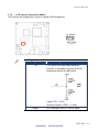
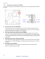
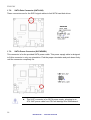
1
User Manual &/91/7 *OUFMÚ"UPN/%%/BOP*59 .PUIFSCPBSE Version March 201 Data Modul AG - www.data-modul.com ENX-PNV Contents 1.1 1.2 Before you Proceed ................................................................................................11 Motherboard Overview............................................................................................12 1.2.1 Placement Direction ....................................................................................................................... 12 1.2.2 Screw Holes ................................................................................................................................... 12 1.3 Motherboard Layout ................................................................................................13 1.3.1 1.4 Layout Content List ........................................................................................................................ 14 System Memory ......................................................................................................15 1.4.1 DIMM Sockets Location ................................................................................................................. 15 1.4.2 Memory Configurations .................................................................................................................. 15 1.4.3 Installing a DDR2 DIMM................................................................................................................. 16 1.4.4 Removing a DDR2 DIMM............................................................................................................... 17 1.5 Expansion slots .......................................................................................................18 1.5.1 MiniPCE Express Location............................................................................................................. 18 1.5.2 Installing an Expansion Card ......................................................................................................... 18 1.5.3 Configuring an Expansion Card ..................................................................................................... 18 1.5.4 MiniPCI express slot....................................................................................................................... 19 1.6 Jumpers ..................................................................................................................19 1.6.1 Clear CMOS (CLRTC).................................................................................................................... 19 1.6.2 COM1, COM2 RI/+5V/+12V Select (JCOMPWR1, JCOMPWR2) ................................................. 20 1.7 Connectors..............................................................................................................21 1.7.1 Rear Panel Connectors .................................................................................................................. 21 This 15-pin port is for a VGA monitor or other VGA-compatible devices. .............................................. 21 LAN (RJ-45) connector ........................................................................................................................... 21 This port connects a headphone or a speaker. In 4-channel, 6-channel, and 8-channel configuration, the function of this port becomes Front Speaker Out. .................................................................................. 21 This power jack is connecting for 12V AC/DC pin 2.5mm power adapter . 12V 40W above is recommended . ....................................................................................................................................... 21 1.7.2 CPU Fan Connector (FAN1) .......................................................................................................... 22 1.7.3 LVDS Connector (JLVDS).............................................................................................................. 22 1.7.4 LCD Inverter Connector (JBKL) ..................................................................................................... 23 1.7.5 System Panel Connector (F_PANEL) ............................................................................................ 24 1.7.6 Serial Port Connector (COM1 & COM2 ) ....................................................................................... 25 1.7.7 Digital I/O Connector (JDIO) .......................................................................................................... 25 1.7.8 SATA Data Connector (SATA1&2) ................................................................................................ 26 1.7.9 SATA Power Connector (SATAPWR1).......................................................................................... 26 1.7.10 Mic-In & Line-In Connector (JAUDIO1) ..................................................................................... 27 1.7.11 USB 3&4 Connector (USB2)...................................................................................................... 27 2 Data Modul AG - www.data-modul.com User’s Manual 2.1 BIOS Setup Program ..............................................................................................29 2.1.1 Legend Box .................................................................................................................................... 30 2.1.2 List Box........................................................................................................................................... 30 2.1.3 Sub-menu ....................................................................................................................................... 30 2.2 BIOS Menu Screen .................................................................................................31 2.2.1 Main................................................................................................................................................ 32 2.2.1.1 System Time.......................................................................................................................... 32 2.2.1.2 System Date .......................................................................................................................... 32 2.2.1.3 Primary IDE Master ............................................................................................................... 33 2.2.1.4 IDE Configuration .................................................................................................................. 35 2.2.1.5 AHCI Setting .......................................................................................................................... 36 2.2.1.6 System Information................................................................................................................ 37 2.2.2 Advanced ....................................................................................................................................... 38 2.2.2.1 CPU Configuration................................................................................................................. 39 2.2.2.2 Chipset................................................................................................................................... 40 2.2.2.3 Onboard Device Configuration .............................................................................................. 42 2.2.2.4 USB Configuration ................................................................................................................. 43 2.2.2.5 Trusted Computing (Optional) ............................................................................................... 44 2.2.2.6 PCI PnP ................................................................................................................................. 45 2.2.3 Power ............................................................................................................................................. 48 2.2.3.1 Suspend Mode....................................................................................................................... 48 2.2.3.2 Repost Video on S3 Resume ................................................................................................ 48 2.2.3.3 ACPI Version Features .......................................................................................................... 48 2.2.3.4 ACPI APIC support ................................................................................................................ 49 2.2.3.5 Power Management .............................................................................................................. 49 2.2.3.6 Hardware Health Configuration ............................................................................................. 51 2.2.4 Boot ................................................................................................................................................ 53 2.2.4.1 Security Settings.................................................................................................................... 54 2.2.4.2 Boot Setting Configuration..................................................................................................... 55 2.2.5 Exit.................................................................................................................................................. 56 2.2.5.1 Save Changes and Exit ......................................................................................................... 57 2.2.5.2 Discard Changes and Exit ..................................................................................................... 57 2.2.5.3 Discard Changes ................................................................................................................... 58 2.2.5.4 Load Setup Defaults .............................................................................................................. 58 ENX-PNV Data Modul AG - www.data-modul.com 3 ENX-PNV Safety Information Electrical safety To prevent electrical shock hazard, disconnect the power cable from the electrical outlet before relocating the system. When adding or removing devices to or from the system, ensure that the power cables for the devices are unplugged before the signal cables are connected. If possible, disconnect all power cables from the existing system before you add a device. Before connecting or removing signal cables from the motherboard, ensure that all power cables are unplugged. Seek professional assistance before using an adapter or extension cord. These devices could interrupt the grounding circuit. Make sure that your power supply is set to the correct voltage in your area. If you are not sure about the voltage of the electrical outlet you are using, contact your local power company. If the power supply is broken, do not try to fix it by yourself. Contact a qualified service technician or your retailer. Operation safety Before installing the motherboard and adding devices on it, carefully read all the manuals that came with the package. Before using the product, make sure all cables are correctly connected and the power cables are not damaged. If you detect any damage, contact your dealer immediately. To avoid short circuits, keep paper clips, screws, and staples away from connectors, slots, sockets and circuitry. Avoid dust, humidity, and temperature extremes. Do not place the product in any area where it may become wet. Place the product on a stable surface. If you encounter technical problems with the product, contact a qualified service technician or your retailer. The symbol of the crossed out wheeled bin indicates that the product (electrical and electronic equipment) should not be placed in municipal waste. Check local regulations for disposal of electronic products. 4 Data Modul AG - www.data-modul.com User’s Manual Safety Declaration This device complies with the requirements in Part 15 of the FCC rules. Operation is subject to the following two conditions: This device may not cause harmful interference. This device must accept any interference received, including interference that may cause undesired operation. Technical Support If a problem arises with your system and no solution can be obtained from the user’s manual, please contact your place of purchase or local distributor. Alternatively, please try the following help resources for further guidance. Visit the Avalue website: http://www.avalue.com.tw Conventions Used in This Guide To make sure that you perform certain tasks properly, take note of the following symbols used throughout this manual. DANGER/WARNING: Information to prevent injury to yourself when trying to complete a task. CAUTION: Information to prevent damage to the components when trying to complete a task. IMPORTANT: Instructions that you MUST follow to complete a task. NOTE: Tips and additional information to help you complete a task. ENX-PNV Data Modul AG - www.data-modul.com 5 ENX-PNV Packing List Before you begin installing your single board, please make sure that the following materials have been shipped: 1 x ENX-PNV Nano-ITX Motherboard 1 x CD-ROM contains the followings: • User’s Manual in PDF file • Drivers 1 x Cable Kit • • • • 2 x COM Cable w/o Bracket (9P/2.00mm) 1 x SATA CABLE 7P 2IN1 L:500mm 1 x SATA power cable (ATX 2x2P) 1 x MD6M to MD6F*2 Cable If any of the above items is damaged or missing, please contact your retailer. 6 Data Modul AG - www.data-modul.com User’s Manual Revision History Revision V 1.0 Revision History First version for PCB 1.1 Date March, 2010 ENX-PNV Data Modul AG - www.data-modul.com 7 ENX-PNV Specifications Summary Specifications System CPU Onboard Intel® Atom™ N450 SC/ D410 SC/D510 DC 1.6GHz Processor FSB DMI (2.5Gbps) x 4 Lanes BIOS AMI/Legacy 16 Mb SPI BIOS System Chipset Intel® ICH8M I/O Chipset Winbond W83627DHG-A Memory Watchdog Timer H/W Status Monitor One 200-pin SODIMM socket supports up to 2GB DDR2 800MHz(D510)/ 667MHz(D410/N450) SDRAM Reset: 1 to 255 sec/min per step Monitoring CPU temperature, voltage, and cooling fan status. Auto throttling control when CPU overheats Expansion Slots 1 x Mini PCIe , 1 x CF DIO 8-bit General Purpose I/O for 4 DI and 4 DO S3 / S4 S1, S3, S4, S5 Wake up on LAN or Ring LAN (PXE), RING (COM1/2) SmartFan Control Supports 3 modes (Silent/Optimal/Performance) TPM Infineon TPM1.2 SLB9635 (optional) Display Chipset Display Memory Max. Resolution Integrated Intel® Gen3.5+GFX Render Core 200MHz (N450/D410)/400MHz (D510) Shared Memory Max 224MB LVDS : Max 1280 x 800 or 1366 x 768 VGA : Max 2048 x 1536 @ 60Hz Dual Display LVDS+VGA VGA On board LVDS 18-bit Single Channel LVDS LVDS Backlight Power 5V and 12V Audio Audio Codec Realtek ALC888, 5.1 + 2 CH HD Audio Audio Interface Line out (jack) , Mic. In & Line in (pin header) Ethernet LAN1 Realtek RTL 8111C Gigabit LAN * Specifications are subject to change without notice. 8 Data Modul AG - www.data-modul.com User’s Manual Block Diagram ENX-PNV Data Modul AG - www.data-modul.com 9 ENX-PNV This chapter describes the main board features and the new technologies it supports. 1 Product introduction 10 Data Modul AG - www.data-modul.com User’s Manual Production Introduction 1.1 Before you Proceed Take note of the following precautions before you install motherboard components or change any motherboard settings. Unplug the power cord from the wall socket before touching any component. Use a grounded wrist strap or touch a safely grounded object or a metal object, such as the power supply case, before handling components to avoid damaging them due to static electricity Hold components by the edges to avoid touching the ICs on them. Whenever you uninstall any component, place it on a grounded antistatic pad or in the bag that came with the component. Before you install or remove any component, ensure that the ATX power supply is switched off or the power cord is detached from the power supply. Failure to do so may cause severe damage to the motherboard, peripherals, and/or components. ENX-PNV Data Modul AG - www.data-modul.com 11 ENX-PNV 1.2 Motherboard Overview Before you install the motherboard, study the configuration of your chassis to ensure that the motherboard fits into it. Refer to the chassis documentation before installing the motherboard. Make sure to unplug the power cord before installing or removing the motherboard. Failure to do so can cause you physical injury and damage motherboard components. 1.2.1 Placement Direction When installing the motherboard, make sure that you place it into the chassis in the correct orientation. The edge with external ports goes to the rear part of the chassis as indicated in the image below. 1.2.2 Screw Holes Place four (4) screws into the holes indicated by circles to secure the motherboard to the chassis. Do not over tighten the screws! Doing so can damage the motherboard. Place this side towards the rear of the chassis. 12 Data Modul AG - www.data-modul.com User’s Manual 1.3 Motherboard Layout ENX-PNV Data Modul AG - www.data-modul.com 13 ENX-PNV 1.3.1 Layout Content List Slots Label Function SO_DIMM 200-pin DDR2 SODIMM slot MINIPCIE1 Mini PCI-e Slot CF Compact Flash Card Note (Rear side) Page 15 18 (Rear side) N/A Jumpers Label Function Note Page CLRTC Clear CMOS 3 x 1 header, pitch 2.54mm 19 JCOMPWR1 COM1 RI/+5V/+12V Select 3 x 2 header, pitch 2.00mm 20 JCOMPWR2 COM1 RI/+5V/+12V Select 3 x 2 header, pitch 2.00mm 20 Note Page Rear Panel Connector Label Function KBMS1 PS/2 keyboard and mouse 6-pin Mini-Din 21 VGA1 VGA Connector D-sub 15-pin, female 21 USB1 USB 1&2 Connector 21 LAN1 RJ-45 Ethernet Connector 21 Audio2 Audio Line-out Port 21 DCIN1 12V DC-In Power Jack Pin ψ2.5mm 21 Internal Connector Label Function Note Page FAN1 CPU Fan Connector 3 x 1 wafer, pitch 2.54mm 22 JLVDS LVDS Connector Hirose DF13S-40DP-1.25V 22 JBKL LCD Inverter Connector 5 x 1 header, pitch 2.00mm 23 FPANEL1 System Panel Connector (USB 5&6) 8 x 2 header, pitch 2.00mm 24 COM1 & 2 Serial Port Connector * 2 5 x 2 header, pitch 2.00mm 25 JDIO Digital I/O Connector 5 x 2 header, pitch 2.00mm 25 SATA1 & 2 SATA Data Connector * 2 7P Male connector 26 SATAPWR1 SATA Power Connector 2 x 2 female box header 26 JAUDIO1 Mic-In & Line-In Connector 5 x 2 header, pitch 2.00mm 27 USB2 USB 3&4 Connector 5 x 2 header, pitch 2.00mm 27 14 Data Modul AG - www.data-modul.com User’s Manual 1.4 System Memory 1.4.1 DIMM Sockets Location The motherboard comes with two 200-pin Double Data Rate 2 (DDR2) SODIMM sockets. A DDR2 module has the same physical dimensions as a DDR DIMM but has a 200-pin footprint compared to the 184-pin DDR DIMM. DDR2 DIMMs are notched differently to prevent installation on a DDR DIMM socket. The following figure illustrates the location of the sockets: 1.4.2 Memory Configurations You can install 256MB, 512MB, 1GB and 2GB DDR2 SDRAM DIMMs into the SODIMM sockets using the memory configurations in this section. Installing DDR2 DIMM other than the recommended configurations may cause memory sizing error or system boot failure. Use any of the recommended configurations. Due to chipset graphic resource allocation, the system may detect less than 2 GB system memory when you installed one 2 GB DDR2 memory modules. This motherboard does not support memory modules FSB less than 667MHz.Make sure that the memory frequency matches the CPU FSB (Front Side Bus). Refer to the Memory frequency/CPU FSB synchronization table. ENX-PNV Data Modul AG - www.data-modul.com 15 ENX-PNV 1.4.3 Installing a DDR2 DIMM Make sure to unplug the power supply before adding or removing DIMMs or other system components. Failure to do so may cause severe damage to both the motherboard and the components. 1. Locate the DIMM socket on the board. 2. Hold two edges of the DIMM module carefully, and keep away of touching its connectors. 3. Align the notch key on the module with the rib on the slot. 4. Firmly press the modules into the socket which will automatically snap into the mounting notch. Do not force the DIMM module in with extra force as the DIMM module only fits in one direction. A DDR2 DIMM is keyed with a notch so that it fits in only one direction. DO NOT force a DIMM into a socket to avoid damaging the DIMM. The DDR2 DIMM sockets do not support DDR/DDR3 DIMMs. DO NOT install DDR/DDR3 DIMMs to the DDR2 DIMM socket. 16 Data Modul AG - www.data-modul.com User’s Manual 1.4.4 Removing a DDR2 DIMM 1. Press the two ejector tabs on the slot outward simultaneously, and then pull out the DIMM module. Support the DIMM lightly with your fingers when pressing the ejector tabs. The DIMM might get damaged when it flips out with extra force. ENX-PNV Data Modul AG - www.data-modul.com 17 ENX-PNV 1.5 Expansion slots 1.5.1 MiniPCE Express Location In the future, you may need to install expansion cards. The following sub-sections describe the slots and the expansion cards that they support. Make sure to unplug the power cord before adding or removing expansion cards. Failure to do so may cause you physical injury and damage motherboard components. 1.5.2 Installing an Expansion Card 1. Before installing the expansion card, read the documentation that came with it and make the necessary hardware settings for the card. 2. Remove the system unit cover (if your motherboard is already installed in a chassis). 3. Remove the bracket opposite the slot that you intend to use. Keep the screw for later use. 4. Align the card connector with the slot and press firmly until the card is completely seated on the slot. 5. Secure the card to the chassis with the screw you removed earlier. 6. Replace the system cover. 1.5.3 Configuring an Expansion Card After installing the expansion card, configure it by adjusting the software settings. 1. Turn on the system and change the necessary BIOS settings, if any. See Chapter 2 for information on BIOS setup. 2. Assign an IRQ to the card if needed. Refer to the tables on the next page. 3. Install the software drivers for the expansion card. 18 Data Modul AG - www.data-modul.com User’s Manual 1.5.4 MiniPCI express slot The miniPCI express slot supports Mini cards for WiFi , Bluetooth, SSD, COM, USB modules, and other cards that comply with the mini Card Rev. 1.2 specifications . The figure below shows the type of full size SSD card that can be installed on a miniPCI express slot. Due to different pin definitions between mini Card Rev. 1.0 to 1.1/1.2 , some Rev.1.0 mini Cards may not work normally on this MiniPCI express slot . 1.6 Jumpers 1.6.1 Clear CMOS (CLRTC) This jumper allows you to clear the Real Time Clock (RTC) RAM in CMOS. You can clear the CMOS memory of date, time, and system setup parameters by erasing the CMOS RTC RAM data. The onboard button cell battery powers the RAM data in CMOS, which include system setup information such as system passwords. To erase the RTC RAM: 1. Turn OFF the computer and unplug the power cord. 2. Remove the onboard battery. 3. Move the jumper cap from pins 1-2 (default) to pins 2-3. Keep the cap on pins 2-3 for about 5~10 seconds, then move the cap back to pins 1-2. 4. Re-install the battery. 5. Plug the power cord and turn ON the computer. 6. Hold down the <Del> key during the boot process and enter BIOS setup to re-enter data. Except when clearing the CMOS, never remove the cap on the CLRTC jumper default position. Removing the cap will cause system boot failure! ENX-PNV Data Modul AG - www.data-modul.com 19 ENX-PNV Normal (Default) 1 Clear CMOS 1 1.6.2 COM1, COM2 RI/+5V/+12V Select (JCOMPWR1, JCOMPWR2) RI (Default) 6 5 +5V 6 5 +12V 5 20 Data Modul AG - www.data-modul.com 6 User’s Manual 1.7 Connectors 1.7.1 Rear Panel Connectors 1 No 1 Label KBMS1 2 3 2 VGA11 Function PS/2 keyboard and mouse connector VGA Connector 3 USB1 USB 1&2 connector 4 LAN1 LAN (RJ-45) connector 4 5 Description The standard PS/2 mouse DIN connector is for a PS/2 mouse. This 15-pin port is for a VGA monitor or other VGA-compatible devices. These two 4-pin Universal Serial Bus (USB) ports are available for connecting USB 1.1/2.0 devices. This port allows Gigabit connection to a Local Area Network (LAN) through a network hub. Refer to the table below for the LAN port LED indications. The optional 10/100 Mbps LAN controller allows 10/100 Mbps connection to a Local Area Network (LAN) through a network hub. SPEED LED Status 6 ACT / LINK LED Description Status Description OFF 10Mbps connection OFF No link Orange 100Mbps connection Green Link Green 1Gbps connection Blinking Data activity 5 Audio2 Audio Line-out Port 6 DCIN1 12V DC-In Power Jack This port connects a headphone or a speaker. In 4-channel, 6-channel, and 8-channel configuration, the function of this port becomes Front Speaker Out. This power jack is connecting for 12V AC/DC pin 2.5mm power adapter . 12V 40W above is recommended . ENX-PNV Data Modul AG - www.data-modul.com 21 ENX-PNV CPU Fan Connector (FAN1) 1.7.2 This connector supports 12V smart fan for onboard heat-sink. Do not forget to connect the fan cable to the fan connector. Insufficient air flow inside the system may damage the motherboard components. This is not a jumper! DO NOT place a jumper cap on the fan connector. 1.7.3 LVDS Connector (JLVDS) This motherboard supports 18-bit single channel LVDS panel. 22 Data Modul AG - www.data-modul.com User’s Manual 1.7.4 LCD Inverter Connector (JBKL) This function will support the control of internal LVDS brightness. Signal Description Signal VR Signal Description For inverter with adjustable Backlight function, it is possible to control the LCD brightness through the VR signal. Vadj=0.75V ~ 4.25V (Recommended: 4.7KΩ, > 1/16W) ENBKL LCD backlight ON/OFF control signal ENX-PNV Data Modul AG - www.data-modul.com 23 ENX-PNV System Panel Connector (F_PANEL) 1.7.5 This connector supports several chassis-mounted functions, and provides additional USB 5 & 6 ports. System Power LED (2-pin PWRLED) This 2-pin connector is for the system power LED. Connect the chassis power LED cable to this connector. The system power LED lights up when you turn on the system power, and blinks when the system is in sleep mode. ATX Power Button/Soft-off Button (2-pin PWRSW) This connector is for the system power button. Pressing the power button turns the system on or puts the system in sleep or soft-off mode depending on the BIOS settings. Pressing the power switch for more than four seconds while the system is ON turns the system OFF. Hard Disk Drive Activity LED (2-pin HDLED) This 2-pin connector is for the HDD Activity LED. Connect the HDD Activity LED cable to this connector. The IDE LED lights up or flashes when data is read from or written to the HDD. Reset Button (2-pin RESET) This 2-pin connector is for the chassis-mounted reset button for a system reboot without turning off the system power. 24 Data Modul AG - www.data-modul.com User’s Manual 1.7.6 Serial Port Connector (COM1 & COM2 ) These 2 connectors are for serial (COM) port. Connect the serial port module cable to this connector, and then install the module to a slot opening at the back of the system chassis. COM 1&2 1.7.7 Digital I/O Connector (JDIO) This connector supports 8-bit General purpose I/O function. ENX-PNV Data Modul AG - www.data-modul.com 25 ENX-PNV SATA Data Connector (SATA1&2) 1.7.8 These connectors are for the SATA signal cables to link SATA hard disk drives. SATA 1&2 1.7.9 SATA Power Connector (SATAPWR1) This connector is for the provided SATA power cable. This power supply cable is designed to fit this connector in only one orientation. Find the proper orientation and push down firmly until the connector completely fits. This 2x2P connector is for SATA power supply, plugging-in an ATX 2x2P power cable from PSU will damage this motherboard . 26 Data Modul AG - www.data-modul.com User’s Manual 1.7.10 Mic-In & Line-In Connector (JAUDIO1) This connector is for the microphone-in and line-in function. 1.7.11 USB 3&4 Connector (USB2) This connector is for USB 2.0 ports. Connect the USB/GAME module cable to any of these connectors, and then install the module to a slot opening at the back of the system chassis. This USB connector complies with USB 2.0 specification that supports up to 480 Mbps connection speed. Never connect a 1394 cable to the USB connectors. Doing so will damage the motherboard! The USB module is purchased separately. ENX-PNV Data Modul AG - www.data-modul.com 27 ENX-PNV This chapter tells how to change the system settings through the BIOS setup menus. Detailed descriptions of the BIOS parameters are also provided. 2 BIOS setup 28 Data Modul AG - www.data-modul.com User’s Manual BIOS Setup 2.1 BIOS Setup Program This motherboard supports a programmable firmware chip that you can update using the provided utility. Use the BIOS Setup program when you are installing a motherboard, reconfiguring your system, or prompted to “Run Setup.” This section explains how to configure your system using this utility. Even if you are not prompted to use the Setup program, you can change the configuration of your computer in the future. For example, you can enable the security password feature or change the power management settings. This requires you to reconfigure your system using the BIOS Setup program so that the computer can recognize these changes and record them in the CMOS RAM of the firmware hub. The firmware hub on the motherboard stores the Setup utility. When you start up the computer, the system provides you with the opportunity to run this program. Press <Del> during the Power-On-Self-Test (POST) to enter the Setup utility; otherwise, POST continues with its test routines. If you wish to enter Setup after POST, restart the system by pressing <Ctrl+Alt+Delete>, or by pressing the reset button on the system chassis. You can also restart by turning the system off and then back on. Do this last option only if the first two failed. The Setup program is designed to make it as easy to use as possible. Being a menu-driven program, it lets you scroll through the various sub-menus and make your selections from the available options using the navigation keys. The default BIOS settings for this motherboard apply for most conditions to ensure optimum performance. If the system becomes unstable after changing any BIOS settings, load the default settings to ensure system compatibility and stability. Select the Load Optimized Defaults from the BIOS menu screen. The BIOS setup screens shown in this section are for reference purposes only, and may not exactly match what you see on your screen. Visit the system builder’s website to download the latest BIOS file for this motherboard ENX-PNV Data Modul AG - www.data-modul.com 29 ENX-PNV Legend Box 2.1.1 The keys in the legend bar allow you to navigate through the various setup menus Key(s) Function Description ← Select Screen ↑↓ Select Item +- Change Option / Field Enter Go to Sub Screen PGDN Next Page PGUP Previous Page HOME Go to Top of Screen END Go to Bottom of Screen F2/F3 Change Colors F7 Discard Changes F8 N/A F9 Load Optimal Defaults F10 Save and Exit ESC Exit 2.1.2 List Box This box appears only in the opening screen. The box displays an initial list of configurable items in the menu you selected. 2.1.3 Sub-menu Note that a right pointer symbol appears to the left of certain fields. This pointer indicates that you can display a sub-menu from this field. A sub-menu contains additional options for a field parameter. To display a sub-menu, move the highlight to the field and press <Enter>. The sub-menu appears. Use the legend keys to enter values and move from field to field within a sub-menu as you would within a menu. Use the <Esc> key to return to the main menu. Take some time to familiarize yourself with the legend keys and their corresponding functions. Practice navigating through the various menus and submenus. If you accidentally make unwanted changes to any of the fields, press <F9> to load the optimal default values. While moving around through the Setup program, note that explanations appear in the Item Specific Help window located to the right of each menu. This window displays the help text for the currently highlighted field. 30 Data Modul AG - www.data-modul.com User’s Manual 2.2 BIOS Menu Screen When you enter the BIOS, the following screen appears. The BIOS menu screen displays the items that allow you to make changes to the system configuration. To access the menu items, press the up/down/right/left arrow key on the keyboard until the desired item is highlighted, then press [Enter] to open the specific menu. ENX-PNV Data Modul AG - www.data-modul.com 31 ENX-PNV Main 2.2.1 Use this menu for basic system configurations, such as time, date etc. 2.2.1.1 System Time The time format is <Hour> <Minute> <Second>. 2.2.1.2 System Date The date format is <Day>, <Month> <Date> <Year>. 32 Data Modul AG - www.data-modul.com User’s Manual 2.2.1.3 Primary IDE Master While entering Setup, the BIOS automatically detects the presence of SATA devices. There is a separate sub-menu for each IDE device. Select a device item then press <Enter> to display the SATA device information. The BIOS automatically detects the values opposite the dimmed items (Device, Vendor, Size, LBA Mode, Block Mode, PIO Mode, Async DMA, Ultra DMA, and SMART monitoring). These values are not user-configurable. These items show Not Detected if no SATA device is installed in the system. Type [Auto] Select the type of SATA drive. Setting to Auto allows automatic selection of the appropriate SATA device type. Select CD/DVD if you are specifically configuring a CD-ROM/DVD-ROM drive. Select ARMD (ATAPI Removable Media Device) if your device is either a ZIP, LS-120, or MO drive. Configuration options: [Not Installed] [Auto] [CD/DVD] [ARMD] ENX-PNV Data Modul AG - www.data-modul.com 33 ENX-PNV LBA/Large Mode [Auto] Enables or disables the LBA mode. Setting to Auto enables the LBA mode if the device supports this mode, and if the device was not previously formatted with LBA mode disabled. Configuration options: [Disabled] [Auto] Block (Multi-Sector Transfer) [Auto] Enables or disables data multi-sectors transfers. When set to Auto, the data transfer from and to the device occurs multiple sectors at a time if the device supports multi-sector transfer feature. When set to [Disabled], the data transfer from and to the device occurs one sector at a time. Configuration options: [Disabled] [Auto] PIO Mode [Auto] Select the PIO mode. Configuration options: [Auto] [0] [1] [2] [3] [4] DMA Mode [Auto] Select the DMA mode. Configuration options: [Auto] [SWDMA0] [SWDMA1] [SWDMA2] [MWDMA0] [MWDMA1] [MWDMA2] [UDMA0] [UDMA1] [UDMA2] [UDMA3] [UDMA4] [UDMA5] [UDMA6]. Only [Auto] is showed if no SATA device is installed in the system. S.M.A.R.T. [Auto] Set the Smart Monitoring, Analysis, and Reporting Technology. Configuration options: [Auto] [Disabled] [Enabled] 32Bit Data Transfer [Enabled] Enables or disables 32-bit data transfer. Configuration options: [Disabled] [Enabled] 34 Data Modul AG - www.data-modul.com User’s Manual 2.2.1.4 IDE Configuration ATA/IDE Configuration [Enhanced] Allows you to set SATA Configuration function. Configuration options: [Compatible] [Enhanced] Configure SATA as [IDE] Allows you to set SATA as function[IDE] or [AHCI] ENX-PNV Data Modul AG - www.data-modul.com 35 ENX-PNV 2.2.1.5 AHCI Setting AHCI Port0 & Port1 SATA AHCI functions for setting are [Auto] [Not Detected] further function settings after SATA devices detected are: AHCI Port0 [Disabled] [Enabled] AHCI Port1 [Disabled] [Enabled] 36 Data Modul AG - www.data-modul.com User’s Manual 2.2.1.6 System Information This menu gives you an overview of the general system specifications. The BIOS automatically detects the items in this menu. AMI BIOS Display the auto-detected BIOS information. Processor Display the auto-detected CPU specification. System Memory Display the auto-detected system memory. ENX-PNV Data Modul AG - www.data-modul.com 37 ENX-PNV Advanced 2.2.2 The Advanced menu items allow you to change the settings for the CPU and other system devices. Take caution when changing the settings of the Advanced menu items. Incorrect field values can cause the system to malfunction. 38 Data Modul AG - www.data-modul.com User’s Manual 2.2.2.1 CPU Configuration The items in this menu allow you to change the CPU-related features. Select an item then press <Enter> to display the configuration options. Max CPUID Value Limit [Disabled] Setting this item to [Enabled] allows legacy operating systems to boot even without support for CPUs with extended CPUID functions. Configuration options are: [Disabled] [Enabled]. Execute Disable Bit [Enabled] Allows you to enable or disable the No-Execution Page Protection Technology. Setting this item to [Disabled] forces the XD feature flag to always return to zero (0). Configuration options: [Disabled] [Enabled]. Hyper-Threading Technology [Enabled] Allows you to enable or disable Intel Hyper-threading technology (HTT) to improve parallel intstruction execution. HTT requires only that the operating system supports multiple processors. It is recommended that you leave it at the default setting of Disabled. Only enable it if you intend to use Hyper-Threading Technology with an operating system that supports it. ENX-PNV Data Modul AG - www.data-modul.com 39 ENX-PNV 2.2.2.2 Chipset The items in this menu allow you to change the Chipset-related features. Select North Bridge Configuration and press <Enter> for further configuration options. DRAM Frequency [Auto] Allows you to set DRAM frequency , Configuration options: [Auto] [667MHz] [800MHz] It is recommended that you leave it at the default setting of Auto. Only Atom D510 CPU supports 800MHz DDR2 SO-DIMM Configure DRAM Timing by SPD [Enable] Allows you to set DRAM timing , Configuration options: [Enable] [Disable] 40 Data Modul AG - www.data-modul.com User’s Manual Video Function Configuration - DVMT Mode Select Dynamic Video Memory Technology (DVMT), for use as video memory to ensure the most efficient use of available resources for maximum 2D/3D graphics performance Configuration options: [Fixed Mode] [DVMT Mode]. - DVMT/FIXED Memory, Configuration options: [128MB] [258MB] [Maximum DTMT]. - Boot Display Device Configuration options: [VBIOS-Default] [CRT] [LVDS] [CRT+LVDS]. - Flat Panel Type , Set for panel resolution , Configuration options: Type 1 640x480 Type 2 800x600 Type 3 1024x768 Type 4 1280x768 Type 5 1280x800 Type 6 1280x600 - Spread Spectrum Clock , Set for panel resolution , Configuration options: [Disable] [Enabled] ENX-PNV Data Modul AG - www.data-modul.com 41 ENX-PNV 2.2.2.3 Onboard Device Configuration SMBUS Controller The options: [Enabled], [Disabled] HDA Controller The options: [Enabled], [Disabled] Onboard Rtl8111 LAN The options: [Enabled], [Disabled] Onboard LAN Boot The options: [Enabled], [Disabled] Mini PciE Port The options: [Enabled], [Disabled] Serial Port1 Address [3F8/IRQ4] Allow you to select the Serial Port1 base address. Configuration options: [Disabled] [3F8/IRQ4] [3E8/IRQ4] [2E8/IRQ3]. Serial Port2 Address [2F8/IRQ3] Allow you to select the Serial Port1 base address. Configuration options: [Disabled] [2F8/IRQ3] [3E8/IRQ4] [2E8/IRQ3]. 42 Data Modul AG - www.data-modul.com User’s Manual 2.2.2.4 USB Configuration The items in this menu allow you to change the USB-related features. Select an item then press <Enter> to display the configuration options. USB Devices Enabled The Module Version and USB Devices Enabled items show the auto-detected values. If no USB device is detected, the item shows None. Legacy USB Support [Enabled] Allows you to enable or disable support for USB devices on legacy operating systems (OS). Setting to Auto allows the system to detect the presence of USB devices at startup. If detected, the USB controller legacy mode is enabled. If no USB device is detected, the legacy USB support is disabled. Configuration options: [Disabled] [Enabled] [Auto] BIOS EHCI Hand-Off [Enabled] Allows you to enable support for operating systems without an EHCI hands off feature. Configuration options: [Disabled] [Enabled]. ENX-PNV Data Modul AG - www.data-modul.com 43 ENX-PNV 2.2.2.5 Trusted Computing (Optional) The items in this menu allow you to set the TPM (Trusted Platform Module) features. Select an item then press <Enter> to display the configuration options. TCG/TPM SUPPORT [YES] Allows you to enable or disable TCG/TPM 1.2 support in BIOS. Configuration options: [No] [Yes]. The following items show when you set TCG/TPM SUPPORT option to [YES]. 44 Data Modul AG - www.data-modul.com User’s Manual 2.2.2.6 PCI PnP The PCI PnP menu items allow you to change the advanced settings for PCI/PnP devices. The menu includes setting IRQ and DMA channel resources for either PCI/PnP or legacy ISA devices, and setting the memory size block for legacy ISA devices. Take caution when changing the settings of the PCI PnP menu items. Incorrect field values can cause the system to malfunction. Clear NVRAM [No] This item is to clear NVRAM during system boot. Configuration options: [No] [Yes]. Plug and Play O/S [No] When set to [No], BIOS configures all the devices in the system. When set to [Yes] and if you install a Plug and Play operating system, the operating system configures the Plug and Play devices not required for boot. Configuration options: [No] [Yes] PCI Latency Timer [64] Allow the PCI Latency Timer to be adjusted. This option sets the latency of all PCI devices on the PCI bus. Configuration options: [32] [64] [96] [128] [160] [192] [224] [248] ENX-PNV Data Modul AG - www.data-modul.com 45 ENX-PNV Allocate IRQ to PCI VGA [Yes] Set this value to allow or restrict the system from giving the VGA adapter card an interrupt address. Configuration options: [No] [Yes] Palette Snooping [Disabled] Set this value to allow or restrict the system from giving the VGA adapter card an interrupt address. Configuration options: [Disabled] [Enabled] Option Description Disabled This is the default setting and should not be changed unless the VGA card manufacturer requires Palette Snooping to be Enabled. Enabled This setting informs the PCI devices that an ISA based Graphics device is installed in the system. It does this so the ISA based Graphics card will function correctly. This does not necessarily indicate a physical ISA adapter card. The graphics chipset can be mounted on a PCI card. Always check with your adapter card’s manual first, before modifying the default settings in the BIOS. PCI IDE BusMaster [Disabled] Set this value to allow or prevent the use of PCI IDE bus-mastering. Configuration options: [Disabled] [Enabled] IRQ [Available] Set this value to allow the IRQ settings to be modified. Interrupt Option Description IRQ3 IRQ4 IRQ5 IRQ7 IRQ9 IRQ10 IRQ11 IRQ14 IRQ15 This setting allows the specified IRQ to be used by a PCI/PnP device. This is the default setting. Available Reserved This setting allows the specified IRQ to be used by a legacy ISA device. 46 Data Modul AG - www.data-modul.com User’s Manual DMA [Available] Set this value to allow the DMA setting to be modified. DMA Channel Option Description DMA Channel 0 Available This setting allows the specified DMA to be used by PCI/PnP DMA Channel 1 device. This is the default setting. DMA Channel 3 DMA Channel 5 DMA Channel 6 Reserved This setting allows the specified DMA to be used by a legacy DMA Channel 7 ISA device. Reserved Memory Size [Disabled] Configuration options: [Disabled] [16K] [32K] [64K] ENX-PNV Data Modul AG - www.data-modul.com 47 ENX-PNV Power 2.2.3 The Power menu items allows you to change the settings for the Advanced Power Management (APM). Select an item then press <Enter> to display the configuration options. 2.2.3.1 Suspend Mode Allows you to select the Advanced Configuration and Power Interface (ACPI) state to be used for system suspend. Configuration options: [S1 (POS)] [S3 (STR)] [Auto]. 2.2.3.2 Repost Video on S3 Resume Determine whether to invoke VGA BIOS post on S3/STR Resume. Configuration options: [Yes] [No] 2.2.3.3 ACPI Version Features Allows you to add more tables for advanced Advanced Configuration and Power Interface (ACPI) 2.0 specifications. Configuration options: [ACPI V1.0], [ACPI V2.0], [ACPI V3.0]. 48 Data Modul AG - www.data-modul.com User’s Manual 2.2.3.4 ACPI APIC support Allows you to enable or disable the Advanced Configuration and Power Interface (ACPI) support in the Application-Specific Integrated Circuit (ASIC). When set to Enabled, the ACPI APIC table pointer is included in the RSDT pointer list. Configuration options: [Disabled] [Enabled]. 2.2.3.5 Power Management You can use this screen to select options for the APM settings. Use the up and down <Arrow> keys to select an item. Use the <Plus> and <Minus> keys to change the value of the selected option. The settings are described on the following pages. The screen is shown below. Power Button Mode [On/Off] The option: [On/Off] [Suspend]. Resume On Ring The option: [Disabled] [Enabled]. ENX-PNV Data Modul AG - www.data-modul.com 49 ENX-PNV Resume On RTC Alarm When [Enabled], you can set the date and time at which the RTC (real-time clock) alarm awakens the system from suspend mode. PS/2 Keyboard WakeUP The option: [Disabled] [Enabled]. PS/2 Mouse WakeUP The option: [Disabled] [Enabled]. Restore on AC Power Loss [Off] When set to [Off], the system goes into off state after an AC power loss. When set to [On], the system goes on after an AC power loss. Configuration options: [Off] [On] [Previous State]. Watchdog Timer (SECOND) Allows you to set time-out of the Watchdog counter. 50 Data Modul AG - www.data-modul.com User’s Manual 2.2.3.6 Hardware Health Configuration You can use this screen for the Hardware Health status. See below. CPU Temperature [xxxºC/xxxºF] The onboard hardware monitor automatically detects and displays the CPU temperature. CHASIS Temperature [xxxºC/xxxºF] The onboard hardware monitor automatically detects and displays the Chassis temperature. CPU Fan Speed [xxxxRPM] The onboard hardware monitor automatically detects and displays the CPU fan speed in rotations per minute (RPM). If the fan is not connected to the motherboard, the field shows N/A. +12VIN / +5VIN / Vcore / VCC / VBAT [xxxx Voltage] The onboard hardware monitor automatically detects the voltage output through the onboard voltage regulators. ENX-PNV Data Modul AG - www.data-modul.com 51 ENX-PNV CPU FAN Profile Mode Allows you to select the CPU FAN profile mode. The options: [Disabled] [Optimal Mode]:Keeps a balance between CPU temperature and fan speed. [Silent Mode] :Keeps the system at a lower acoustic than Optimized mode with lower fan speed. [Performance Mode]:Keeps the CPU at a lower temperature than Optimized mode with faster fan speed. 52 Data Modul AG - www.data-modul.com User’s Manual 2.2.4 Boot The Boot menu items allow you to change the system boot options. Select an item then press <Enter> to display the sub-menu. ENX-PNV Data Modul AG - www.data-modul.com 53 ENX-PNV 2.2.4.1 Security Settings The Security menu items allow you to change the system security settings. Select an item then press <Enter> to display the configuration options. Supervisor/User Password The Supervisor/User Password item on top of the screen shows the default Not Installed. After you set a password, this item shows Installed. Change Supervisor/User Password (1) Select the Change Supervisor/User Password item and press <Enter> (2) From the password box, type a password composed of at least six letters and/or number, the press <Enter>. (3) Confirm the password when prompted. The message “Password Installed” appears after you successfully set your password. To clear the supervisor/user password, select the change Supervisor/User Password then press <Enter>. The message “Password Uninstalled” appears. After you have set a supervisor password, the other items appear to allow you to change other security settings. If you forget your BIOS password, you can clear it by erasing the CMOS Real Time Clock (RTC) RAM. 54 Data Modul AG - www.data-modul.com User’s Manual 2.2.4.2 Boot Setting Configuration Quick Boot [Enabled] Enabling this item allows the BIOS to skip some Power On Self Tests (POST) while booting to decrease the time needed to boot the system. When set to [Disabled], BIOS performs all the POST items. Configuration options: [Disabled] [Enabled] Quiet Boot Allows you to display Normal POST message or OEM logo. The options: [Disabled], [Enabled] AddOn ROM Display Mode [Force BIOS] Set the display mode for ROM option. Configuration options: [Force BIOS] [Keep Current] Bootup Num-Lock [On] Allows you to select the power-on state for the NumLock. Configuration options: [Off] [On] ENX-PNV Data Modul AG - www.data-modul.com 55 ENX-PNV Wait for ‘F1’ If Error [Enabled] When set to Enabled, the system waits for the F1 key to be pressed when error occurs. Configuration options: [Disabled] [Enabled]. 2.2.5 Exit The Exit menu items allow you to load the optimal or failsafe default values for the BIOS items, and save or discard your changes to the BIOS items. Press <ESC> does not immediately exit this menu. Select on of the options from this menu or <F10> from the legend bar to exit. 56 Data Modul AG - www.data-modul.com User’s Manual 2.2.5.1 Save Changes and Exit Once you are finished making your selections, choose this option from the Exit menu to ensure the values you selected are saved to the CMOS RAM. An onboard backup battery sustains the CMOS RAM so it stays on even when the PC is turned off. When you select this option, a confirmation window appears. Select [OK] to save change and exit. 2.2.5.2 Discard Changes and Exit Select this option only if you do not want to save the changes that you made to the setup program. If you made changes to fields other than System Date, System time, and Password, the BIOS asks for a confirmation before exiting. ENX-PNV Data Modul AG - www.data-modul.com 57 ENX-PNV 2.2.5.3 Discard Changes This option allows you to discard the selections you made and restore the previously saved values. After selecting this option, a confirmation appears. Select [OK] to discard any changes and load the previously saved values. 2.2.5.4 Load Setup Defaults This option allows you to load the setup default values for each of the parameters on the Setup menus. When you select this option or if you press <F5>, a confirmation window appears. Select [OK] to load optimal default values. Select [Save Change and Exit] or make other changes before saving the values to the non-volatile RAM. 58 Data Modul AG - www.data-modul.com Data Modul Headquarters Munich Landsberger-Str. 322 D-80687 Munich - Germany Tel.: +49-89-56017-0 Sales Office Duesseldorf Fritz-Vomfelde-Str. 8 D-40547 Duesseldorf - Germany Tel.: +49-211-52709-0 Sales Office Hamburg Borsteler Chaussee 51 D-22453 Hamburg - Germany Tel.: +49-40-42947377 - 0 Data Modul France, S.A.R.L. Bat B - Hall 204 1-3 Rue des Campanules 77185 Lognes - France Tel.: +33-1-60378100 Data Modul Italia, S.r.l. Regus Center Senigallia Via Senigallia 18/2 20161 Milano - Italy Tel.: +39-02-64672-509 Data Modul Iberia, S.L. c/ Adolfo Pérez Esquivel 3 Edificio Las Americas III Oficiana 40 28230 Parque Empresarial Madrid Las Rozas - Spain Tel.: +34-916 366 458 Data Modul Ltd. / UK 3 Brindley Place Birmingham B 12JB United Kingdom Tel.: +44-121-698-8641 Data Modul Inc. / USA 275 Marcus Blvd, Unit K Hauppauge, NY 11788 USA Tel.: (631)-951-0800 www.data-modul.com [email protected]