1
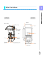
Mor
et
hanj
us
taPOS,
y
out
hi
nk
P5000
Us
er
’
sMANUAL
INDEX
Chapter 1. Caution.
Product quality guarantee
Copyright
Disclaimer
Trademark recognition
Federal Communication Commission
Declaration of conformity
Caution for safety
4
5
6
7
8
9
10
Chapter 2. Product Overview.
Check the contents
Option device
Each part of main body name
Front image
Rear image
Rear connection I/O
Customer display (VFD) installation
Second display installation
Dummy cover installation
Connect keyboard
Connecting printer
Connecting barcode scanner
Connecting cash drawer
Connecting ethernet
Connecting USB device
Connecting Spk & MIC
Connecting power cable
Turn the POS on
Turn the POS off
Support OPOS driver
12
12
13
13
13
14
15
15
16
17
18
19
20
21
22
23
24
25
26
27
Chapter 3. BIOS Setup Utility
BIOS set up utility
BIOS menu screen
Standard CMOS features
Advance BIOS features
Advance chipset features
Integrated peripherals
Power Management set up
PnP/PCI configurations
PC Health Status
Load set up defaults
Set passwords
Save & Exit setup option
Exit without saving
29
31
32
33
35
36
41
43
44
45
46
47
48
Chapter 4. Trouble shooting
General checkout guidelines
Power system checkout
Network symptom
MSR symptom
USB symptom
Cash drawer symptom
LCD screen symptom
Touch screen symptom
Power symptom
PS/2 KB symptom
Boot symptom
50
50
51
51
51
52
52
52
53
53
53
Chapter 5. Mainboard Jumper Setting
Motherboard and deeps
location description
Serial port power setting
COMS Clear
Chapter 6. Replacing Parts
Safety and Precautions
Before you Begin
Interface cover
Motherboard
MSR
Memory
Heatsink & FAN
CPU
HDD
Power supply
Roll paper
LCD monitor
Reference to upgrade
Power supply
Specifications
55
58
59
61
62
63
64
65
66
67
68
69
70
71
72
73
73
74
Chapter 1.
Caution.
>>
Product quality guarantee
POSBANK warrants our hardware POS terminal product and its par ts against defects in materials and workmanship under
normal use for a standard period of two (2) year from the date of original purchase.
During this period, POSBANK will repair or replace a defective product or part without charge for parts and labor to the
purchaser.
The 1st year is free workmanship and new or refurbished replacement parts with one-way freight cost born by POSBANK
and customer shall be responsible for send shipping charge.
2nd year is also no charge for workmanship and parts but limited warranty with round-way freight cost born by customer.
Products outside of the warranty period or scope shall be diagnosed at customer's expense.
POSBANK will require customer's repair and payment authorization to proceed with any repairs.
4
>>
Copyright
This publication, including all photographs, illustrations and software, is protected under international copyright laws, with all rights reserved.
Neither this manual, nor any of the material contained herein, may be reproduced without written consent of the author.
5
>>
Disclaimer
The information in this document is subject to change without notice.
The manufacturer makes no representations or warranties with respect to the contents hereof and specifically disclaims any implied warranties
of merchantability or fitness for any particular purpose.
The manufacturer reserves the right to revise this publication and to make changes from time to time in the content hereof without obligation of
the manufacturer to notify any person of such revision or changes.
6
>>
Trademark recognition
All product names used in this manual are the properties of their respective owners and are acknowledged.
7
>>
Federal communications commission (FCC)
This equipment has been tested and found to comply with the limits for a Class A digital device, pursuant to Part 15 of the FCC Rules.
These limits are designed to provide reasonable protection against harmful interference in a residential installation.
This equipment generates, uses, and can radiate radio frequency energy and, if not installed and used in accordance with the instructions, may
cause harmful interference to radio communications.
However, there is no guarantee that interference will not occur in a particular installation.
If this equipment does cause harmful interference to radio or television reception, which can be determined by turning the equipment off and on, the
user is encouraged to try to correct the interference by one or more of the following measures:
- Reorient or relocate the receiving antenna.
- Increase the separation between the equipment and the receiver.
- Connect the equipment onto an outlet on a circuit different from that to which the receiver is connected.
Shielded interconnect cables and a shielded AC power cable must be employed with this equipment to ensure compliance with the pertinent RF
emission limits governing this device.
Changes or modifications not expressly approved by the system's manufacturer could void the user's authority to operate the equipment.
8
>>
Declaration of conformity
This device complies with part 15 of the FCC rules. Operation is subject to the following conditions:
- This device may not cause harmful interference, and
- This device must accept any interference received, including interference that may cause undesired operation.
9
>>
Caution for safety
-
Specifications are subject to change without notice.
Avoid exposing the product to direct sunlight and do not use the product near area of high moistures.
Do not block the unit's ventilation openings.
Do not attempt to disassemble or modify this product by yourself, as doing so may expose you to an electric shock.
All servicing should be performed by qualified personnel and should confirm to all local codes.
-
If and abnormal power conditions or blackouts occur during operation, disconnect unit at the AC source immediately.
Once normal power is restored, reconnect the AC source.
To avoid unit failure or intermittent operation, check power and other I/O cables are connected correctly.
Always unplug the power cord from the AC outlet before cleaning the product. Use a soft cloth to clean the product.
Do not use solvents or abrasives and do not spray or pour any liquid directly onto product's screen or case.
10
>>
Check the contents
2
3. Optional Parts
1. Firstly, check the user manual on the shown packing
list as written contents
[ VFD ]
2. Basically, POSBAK provide POS main body, power
cord, User's guide, Driver CD, thermal receipt printer
roll paper however, we are not provided roll paper if
our POS is not integrated with printer.
Thermal receipt printer paper
User's manual,
[ 12.1" LCD Monitor ]
Driver cd
Pos Mainbody
Power cord
※ You can download user manual and driver CD from our
(www.posbank.com) home page.
Preparation before installation
1. Firstly, remove the touch protection flim on the screen.
It may cause malfunction if you do not remove the flim.
2. Installation the options first, in case you like to install
option device such as VFD or rear display device.
12
>>
Each part of main body name
2
FRONT VIEW
REAR VIEW
Display Hinge
Power, HDD, LAN LED
LCD & Touch panel display
Option Cover
MSR
(Magnetic Card Reader)
Smart Card Reader
Back Cover
MSR
Paper feed button
Power button
Paper cover
open button
Paper out LED
Receipt Printer (Thermal receipt PRT)
Rubber feet
Side I/O connector
13
>>
Each part of main body name
2
Rear Connectors I/O
1.
2.
3.
4.
AC IN Power Connector
PS/2 Keyboard Connector
PS/2 Mouse Connector
COM1, COM2, COM3 port
5.
6.
7.
8.
1.
2.
3.
4.
Exterior Monitor Connector or DVR port (option))
Cash Drawer Connector
USB Connector
LAN Connector
Multimedia display Ethernet port(option)
Multimedia display Speaker Out port(option)
USB Connector (3 port)
Parallel port (option)
Parallel port will be attachable if there is not
integrated printer of POS product
14
>>
Option parts installation
2
Customer Display(VFD) & 2nd Monitor Installation
Connecting cable to
main body
Connected VFD(second Display)
and hinge by screw
1. VFD test method: It is succeed installed O/S when display the basic picture on the screen after re-power POS product
2. 2nd monitor test method: There is no problem in installation if display initial screen is OK after re-booth
3. VFD or second displays are used by connecting interior of COM4 port
- POSBANK will be providing necessary information in order to operate VFD and POS program.
- VFD is only support English and EPSON mode is available.
※ You should set com4, bit/sec(b):9600, DataBit(D):8, parity(P): nothing, flow-control in no in application program
Environment setting and it operate properly.
Caution;
To install or withdraw VFD(2nd Monitor), power must be switch off.
15
>>
Dummy cover installation
2
Dummy cover installation
* POSBANK basically provide mostly Dummy cover
16
>>
Connects keyboard with mouse
2
Connect keyboard
Connect mouse
※ Warring : The system can be failed if you input wrong port with keyboard and mouse
17
>>
Connecting printer
2
Connecting printer
Connecting right interface with each of serial printer, Parallel, USB port.
※ If you purchased our POS model that printer is not embedded this device can connect parallel port and 24V (2.3A)
printer power to side I/O.
Warring : You should check the printer whether it uses it is does not support this specification.
You should use other adapter.
Connecting parallel printer
Power cable
Parallel cable
Side I/O
18
>>
Connecting barcode scanner
2
Connecting barcode scanner
Our barcode scanner usually uses PS2/2 USB and serial type of interface
You should adjust setting value to the system if scanner supports serial interface type.
- Adjust setting value by manually in case, scanner is set auto mode.
19
>>
Connecting cash drawer
2
Connecting cash drawer
Cash drawer connector (RJ11) is located in the rear of I/O, this connector (RJ11) supports 24V Solenoid type
Cash drawer is connected to internal printer of mother board. Our POS is not operating properly if there is no
integrated printer in the POS product. In this case, connect cash draw port to the exterior printer port
20
>>
Connecting ethernet
2
Connecting ethernet
Ethernet port is located in the rear of I/O, this Ethernet support 10/100/1000Mbps speed,
and connector type is RJ45.
LAN LED will be lighting in case line is connected properly.
21
>>
Connecting USB device
2
Connecting USB device
There are 2 USB ports in the rear I/O, and 3 USB ports in the side I/O.
There is a case that you should install other driver software in USB device.
Our USB device can be malfunctioned if connected lots of line at once. In this case, it is better to use USB hub by
exterior adapter. Some of USB device can be delay recognize according to USB device.
22
>>
Connecting Speaker and mic
2
Connecting microphone
Connecting speaker
23
>>
Connecting power cable
2
Connecting power cable
Our POS support 110V ~240V.
There is no transfer power switcher.
- It must be grounding cable when you connect A/C power cord
1. Connect power cord to the rear of I/O
2. Press ON button that is left side
positioned
24
>>
Turn the POS ON
2
Turn the POS on
Power on peripheral device first before POS switched on.
POSBANK logo will be display or self test on the screen after power on.
Check window boot whether it is operating properly.
1. Press ON button that is
2. Power LED is lighting
3. Start window p/g
left side positioned
25
>>
Turn the POS OFF
2
Turn the POS off
Firstly, turn off Windows for the safety of device.
Close application program before turning off Windows.
1. Click the computer off at
initial windows mode
2. Click button (turn off)
※ Press power switch if you
like to power off by power
switcher
26
>>
Introduction system driver
2
Support OPOS driver
O/S is support WIN XP
You can download it from our website if you like to get the latest OPOS version
Support peripheral device, Cash drawer, CDP, MSR (Magnetic Card Reader), Printer
OPOS driver installation route
Installation driver for POS terminal. (Description of folder contents)
1. CHIP SET DRV installation
2. VIDEO (VGA) DRV installation
3. TOUCH DRV installation
4. AUDIO DRV installation method
5. LAN DRV installations
6. User’s Manual
27
>>
Bios setup utility
3
This motherboard supports a programmable firmware chip that you can update using the provided utility.
Use the BIOS Setup program when you are installing a motherboard, reconfiguring your system, or prompted to "Run Setup."
This section explains how to configure your system using this utility.
Even if you are not prompted to use the Setup program, you can change the configuration of your computer in the future.
For example, you can enable the security password feature or change the power management settings.
This requires you to reconfigure your system using the BIOS Setup program so that the computer can recognize these changes
and record them in the CMOS RAM of the firmware hub.
The firmware hub on the motherboard stores the Setup utility. When you start up the computer, the system provides you with
the opportunity to run this program.
Press <Del> during the Power-On-Self-Test(POST)toenter the Setup utility; otherwise, POST continues with its test routines.
If you wish to enter Setup after POST, restart the system by pressing <Ctrl+Alt+Delete>, or by pressing the reset button on the
system chassis.
You can also restart by turning the system off and then back on. Do this last option only if the first two failed.
The Setup program is designed to make it as easy to use as possible.
Being a menu-driven program, it lets you scroll through the various sub-menus and make your selections from the available
options using the navigation keys.
■ The default BIOS settings for this motherboard apply for most conditions to ensure optimum performance.
If the system becomes unstable after changing any BIOS settings, load the default settings to ensure system
compatibility and stability.
Select the Load Optimized Defaults from the BIOS menu screen.
■ The BIOS setup screens shown in this section are for reference purposes only, and may not exactly match what you
see on your screen.
29
>>
Bios setup utility
3
You should be careful in BIOS change and it may cause malfunction or break-up in case you change it without full
comprehension.
Set-up (DEL)
After pressing [power] button, when system starts, click [DEL] key or shown screen message Press [Del] to enter
SETUP after pressing [Del] key then system set up screen changed.
Key(s )
Function Description
F1
General help, only for Status Page Setup Menu and Option Page Se tup Menu
Esc
Return to the main menu from a submenu or prompts you to quit the setup program.
←, →
Move to the item in the left or right hand
↑, ↓
Move to previous or next item
Enter
Brings up a selection menu for the highlighted field.
+ or PgUp
Moves the cursor to the first field
- or PgDn
Moves the cursor to the last field
(Shift) F2 key
F5
F6, F7
F10
Change color from total 16 colors. F2 to select color forward, ( Shift) F2 to select color backward
Loads the previous values
Loads the fail-safe / optimized defaults
Saves changes and exits Setup
30
>>
Bios setup utility
3
BIOS Menu Screen
When you enter the BIOS, the following screen appears.
The BIOS menu screen displays the items that allow you to make changes to the system configuration.
To access the menu items, press the up/down/right/left arrow key on the keyboard until the desired item is highlighted,
then press [Enter] to open the specific menu.
31
>>
Bios setup utility
3
Standard BIOS Features.
The Standard CMOS Features screen gives you an overview of the basic system
Date [Day, xx/xx/xxxx]
The date format is <week>, <month>, <day>, <year>.
Time [xx:xx:xx]
The time format is <hour><minute><second>, based on the 24-hour
clock.
IDE Channel 0/1 Master / Slave
- IDE HDD Auto-Detection : [Press Enter] to select this option for automatic device detection.
- IDE Primary Master :
[Auto]: Automatically detects IDE devices during POST
[None]: Select this when no IDE device is used.
The system will skip the auto-detection setup to make system start up faster.
[Manual]: User can manually input the correct settings.
- Access Mode: The options are CHS/LBA/Large/Auto
- Capacity: Capacity of currently installed hard disk
- Cylinder: Number of cylinders
- Head: Number of heads
- Precomp: Write precomp
- Landing Zone: Landing zone
- Sector: Number of sectors
Halt On
Set the system to halt on errors according to the system functions
specified in each option.
Configuration options: [All Errors] [No Errors] [All, But Keyboard]
Video
This category detects the type of adapter used for the primary monitor that
must match your video display card and monitor.
- EGA / VGA: Enhanced Graphics Adapter/Video Graphics Array.
For EGA, VGA, SVGA, or PGA monitor adapters.
- CGA 40: Color Graphics Adapter, power up in 40 column mode.
- CGA 80: Color Graphics Adapter, power up in 80 column mode.
- MONO: Monochrome adapter includes high resolution monochrome adapters.
32
>>
Bios setup utility
3
Advanced BIOS Features.
The "Advanced BIOS Features" screen appears when choosing the "Advanced BIOS Features" item from the "Initial Setup
Screen" menu. It allows the user to configure the motherboard according to his particular requirements.
Below are some major items that are provided in the Advanced BIOS Features screen.
A quick booting function is provided for your convenience.
Simply enable the Quick Booting item to save yourself valuable time.
CPU Features
This item allows you to setup the CPU thermal management function.
Delay Prior to Thermal
With the default value of 16 Minutes, the BIOS activates the Thermal
Monitor in automatic mode 16 minutes after the system starts booting up.
The options: [4 Min], [8 Min], [16 Min], [32 Min].
Hard Disk Boot Priority
Set hard disk boot device priority.
CPU L 1 & L2 Cache
Enabling this feature speeds up memory access.
Quick Power On Self Test
This allows the system to skip certain tests to speed up the boot-up
procedure.
First / Second / Third Boot Device
The BIOS tries to load the OS from the devices in the sequence set here.
33
>>
Bios setup utility
3
Advanced BIOS Features.
Boot Other Device
Use this to boot another device. The options are “Enabled” and “Disabled”
Boot Up NumLock Status
Set the boot up Num Lock status. The options are “On” and “Off”.
Gate A20 Option
Normal : A pin in the keyboard controller controls GateA20
Fast : Lets chipset control GateA20 (Default)
Typematic Rate Setting
The typematic rate is the rate key strokes repeat as determined by the keyboard
controller.
The commands are "Enabled" or "Disabled".
Enabling allows the typematic rate and delay to be selected.
Security Option
This category determines whether the password is required when the system boots
up or only when entering setup. The options are:
- System : The system will not boot and access to Setup will be denied if the correct
password is not entered at the prompt.
- Setup : The system will boot, but access to Setup will be denied if the correct
password is not entered at the prompt.
APIC Mode
This setting allows you to enable the APIC mode.
The choices are "Disabled" or "Enabled"
MPS Version Control for OS
This option is only valid for multiprocessor motherboards as it specifies the version of the Multiprocessor Specification (MPS) that the motherboard will use.
The MPS is a specification by which PC manufacturers design and build Intel architecture systems with two or more processors. MPS 1.1 was the original specification.
MPS version 1.4 adds extended configuration tables for improved support of multiple PCI bus configurations and greater expandability in the future.
In addition, MPS 1.4 introduces support for a secondary PCI bus without requiring a PCI bridge.
Delay for HDD (Secs)
The default is [0].
Small Logo (EPA) Show
This item allows you enabled/disabled the small EPA logo show on screen at the POST step.
34
>>
Bios setup utility
3
Advanced Chipset Features.
DRAM Timing Selectable
This item allows you to select the DRAM timing value by SPD data or Manual by
yourself. The choices: Manual, By SPD.
System BIOS Cacheable
Selecting "Enabled" allows caching of the system BIOS ROM at F0000h- FFFFFh,
resulting in better system performance.
However, if any program writes data to this memory area, a system error may occur.
The Choices are "Enabled" and "Disabled"
Video BIOS Cacheable
This feature is only valid when the video BIOS is shadowed.
It enables or disables the Caching of the video BIOS ROM at C0000h-C7FFFh via
the L2 cache.
This greatly speeds up accesses to the video BIOS.
However, this does not translate into better system Performance because the OS
bypasses the BIOS using the graphics driver to access the video card's hardware
directly. The Choice: Enabled, Disabled.
Memory Hole at 15M-16M
Enabling this feature reserves 15 MB to 16 MB memory address space for ISA expansion cards that specifically require this setting. This makes memory from 15 MB and
up unavailable to the system. Expansion cards can only access memory up to 16 MB.
The default setting is "Disabled"
On-Chip Frame Buffer Size
The On-Chip Frame Buffer Size can be set to 1 MB or 8 MB. This memory is shared with the system memory.
DVMT Mode
Use this field to select the memory to allocate for video memory. The choices are “Fixed”, “DVMT” and “BOTH”.
DVMT/FIXED Memory Size
Specify the size of DVMT/system memory to allocate for video memory. The options: [64MB], [128MB]
Boot Display
The options: [Auto], [CRT], [LFP], [CRT+LFP], [DVI]
Panel Number The options:
[640x480 18bit] [800x600 18bit] [1024x768 18bit] [1280x1024 18bit/2] [1400x1050 18bit/2] [1400x1050 18bit/2] [1600x1200 18bit/2] [1280x768 18bit] [1680x1050 18bit/2]
[1920x1200 18bit/2] [1024x768 18bit/2] [1024x768 24bit] [1024x768 18bit] [1280x800 24bit] [1280x600 18bit] [2048x1536 18bit/2]
35
>>
Bios setup utility
3
Integrated Peripherals
Use this menu to specify your settings for integrated peripherals.
36
>>
Bios setup utility
3
Integrated Peripherals
[On Chip IDE Device]
IDE HDD Block Model
If the IDE hard drive supports block mode select Enabled for automatic detection of the optimal number of block
read/writes per sector the drive can support.
IDE DMA Transfer Access
Use this field to enable or disable IDE DMA transfer access.
On-Chip Primary / Secondary PCI IDE
The chipset contains a PCI IDE interface with support for two IDE channels. Select Enabled to active the primary /
secondary IDE interface. Select Disabled to deactivate this interface.
The options: [Enabled], [Disabled]
IDE Primary/Secondary Master/Slave PIO/UDMA
The channel has both a master and a slave, making four IDE devices possible. Because two IDE devices may have
a different Mode timing (0, 1, 2, 3, 4), it is necessary for these to be independent.
The default setting "Auto" will allow auto detection to ensure optimal performance.
On-Chip Serial ATA
The chipset contains a SATA IDE interface with support for two IDE channels. Select Enabled to activate the primary IDE interface (Channel0).
Select Disabled to deactivate this interface. The options: Disabled, Auto, Combined Mode, SATA Only.
Azalia/AC97 Audio Select
This item allows you to Enabled/Disabled Azalia/AC97 chipset.
The options: Auto, AC97 Audio only, Disabled.
[Onboard Device]
37
>>
Bios setup utility
3
Integrated Peripherals
[Super I/O Device]
Power ON Function
This feature allows you to wake up the system using any of the listed options.
The options: [Mouse Left], [Mouse Right], [Any KEY], [Button Only].
Onboard Serial Port
Select an address and corresponding interrupt for the first and second serial ports.
The choice: [Disabled], [3F8/IRQ4], [2F8/IRQ3], [3E8/IRQ4], [2E8/IRQ3]
POWER After PWR-fail
The options are [off], [on].
38
>>
Bios setup utility
3
Integrated Peripherals
Onboard LAN Boot ROM
The options are [disabled], [enable].
Watch Dog Timer Select
This option will determine watchdog timer.
The choices: Disabled, 10, 20, 30, 40 Sec. 1, 2, 4 Min.
Onboard Serial Port 3
Select an address and corresponding interrupt for the serial ports.
The choice: [Disabled], [3F8], [2F8], [3E8], [2E8].
Serial Port 3 Use IRQ
Select an IRQ for the serial ports.
The options: IRQ3, IRQ4, IRQ5, IRQ7, IRQ10, IRQ11
Onboard Serial Port 4
Select an address and corresponding interrupt for the serial ports.
The choice: [Disabled], [3F8], [2F8], [3E8], [2E8].
Serial Port 4 Use IRQ
Select an IRQ for the serial ports.
The options: IRQ3, IRQ4, IRQ5, IRQ7, IRQ10, IRQ11
39
>>
Bios setup utility
3
Integrated Peripherals
[USB Device Setting]
USB 1.0 / 2.0 Controller
The choices: Disabled, Enabled.
USB Operation Mode
Allow you to configure the USB 2.0 controller in HiSpeed (480 Mbps)
or Full Speed (12 Mbps).
Configuration options: [Full/Low Speed] [HiSpeed]
USB Keyboard Function
The choices: Disabled, Enabled.
USB Mouse Function
The choices: Disabled, Enabled.
USB Storage Function
The choices: Disabled, Enabled.
40
>>
Bios setup utility
3
Power Management Setup.
The power management setup controls the single board computer's "green" features to save power.
The following screen shows the manufacturer's defaults.
ACPI Function
The choices are “Enabled” and “Disabled”.
ACPI Suspend Type
This item allows you to set ACPI suspend type to S1/POS(Power On Suspend)
or S3/STR (Suspend To RAM).
Run VGABIOS if S3 Resume
Select “Auto” to run VGA BIOS if S3 resume automatically.
The "Yes" enables running VGA BIOS if S3 resume.
The "No" disables this function.
Power Management
There are three selections for Power Management, and each of them has
fixed mode settings
Video OFF Method
Use this to select the method to turn off the video.
Video OFF In Suspend
When the system is in suspend mode, the video will turn off.
Suspend Type
Select the suspend type. The choice: Stop Grant, Pwron suspend.
MODEM Use IRQ
This determines the IRQ in which the MODEM can use. The choices: NA, 3, 4, 5, 7, 9, 10, 11.
Suspend Mode
The item allows to set the number of minutes before the system enters suspend mode.
HDD Power Down
Select “1-15 mins.” to enable HDD Power Down mode between 1 to 15 mins. Select “Disabled” to disable HDD Power Down function.
Soft-off by PWR-BTTN
If you choose “Instant-Off”, then pushing the ATX soft power switch but- ton once will switch the system to “system off” power mode.
You can choose “Delay 4 sec”. If you do, then pushing the button for more than 4 seconds will turn off the system, whereas pushing the button momentarily (for less than 4 seconds)
will switch the system to “suspend” mode.
41
>>
Bios setup utility
3
Power Management Setup.
Wake-Up by PCI Card
This will enable the system to wake up through PCI/LAN peripheral.
The choices: Enable, Disabled.
Power On by Ring
Select “Enabled” to power on the system from a soft off state by an
input signal on the serial Ring Indicator (RI) line.
The choices are “Enabled” and “Disabled”.
USB KB Wake-Up from S3
When “Enabled”, enter any key to wake up the system from S3 state.
The choices are “Enabled” and “Disabled”.
Resume by Alarm
When “Enabled”, set the date and time at which the RTC (real-time clock)
alarm awakens the system from suspend mode.
The choices are “Enabled” and “Disabled”
42
>>
Bios setup utility
3
PnP/PCI Configurations
Rest Configuration Data
The default is “Disabled”. Select Enabled to reset Extended System
Configuration Data (ESCD) if you have installed a new add-on card, and
system configuration is in such a state that the OS cannot boot.
Resource Controlled By
The commands here are “Auto(ESCD)” or “Manual”.
Choosing “Manual” requires you to choose resources from the following
sub-menu.“Auto(ESCD)” automatically configures all of the boot and
Plug and Play devices, but you must be using Windows 95 or above.
PCI/VGA Palette Snoop
This is set to “Disabled” by default.
INT Pin 1/2/3/4/5/6/7/8 Assignment
The choices: Auto, 3, 4, 5, 7, 9, 10, 11
Maximum Payload Size
This allows you to set the maximum TLP payload size for PCI Express
devices.
The options: [128 bytes], [256 bytes], [512 bytes], [1024 bytes],
[2048 bytes], [4096 bytes].
43
>>
Bios setup utility
3
PC Health Status
System Temperature
This shows you the current temperature of system.
CPU Temperature
This shows the current CPU temperature.
Chassis FAN Speed
This shows the Chassis FAN Speed (RPM).
CPU FAN Speed
This shows the CPU FAN Speed.(RPM)
VCore and Others Voltage
This shows the voltage of VCORE, +5V, +12V, VCC(V), AVCC(V),
VCC3(V), VBAT(V), and 3VSB(V).
44
>>
Bios setup utility
3
Load Setup Defaults
Use this menu to load the BIOS default values that are factory settings for optimal performance system operations.
While Award has designed the custom BIOS to maximize performance, the factory has the right to change these defaults
to meet their needs.
Press <Y> to load the default values setting for optimal performance system operations.
45
>>
Bios setup utility
3
Set Password.
You can set password. It is able to entel / change the options of setup menus.
46
>>
Bios setup utility
3
Save and Exit Setup.
If you select this and press <Enter>, the values entered in the setup utilities will be recorded in the CMOS memory of the
chipset.
The processor will check this every time you turn your system on and compare this to what it finds as it checks the
system. This record is required for the sys- tem to operate.
47
>>
Bios setup utility
3
Exit without saving
Selecting this option and pressing <Enter> lets you exit the setup program without recording any new values or changing
old ones.
48
>>
Trouble shooting
4
General checkout guidelines
Use the following procedure to troubleshoot problems:
- Identify as many symptoms as possible in detail.
- Verify symptoms by recreating them.
- Follow the corrective procedures in order.
- If you replace an FRU and the symptom remains, reinstall the original FRU before going to the next step.
Do not replace non-defective FRUs.
Power system checkout
Power system problems can result from a faulty ac adapter, or undetermined problems (such as loose connections).
Refer to the following to check the ac adapter..
50
>>
Trouble shooting
Network Symptom
Cannot access LAN
4
-
Check hub / switch is working correctly
Check the RJ45 cable
Check the RJ-45 LEDs are on
Reinstalled LAN card
Replace main board
MSR Symptom
MSR does not response
USB Symptom
USB port does not function
- Check the MSR reader cable
- Check the main board to LCD cable
- Check the MSR board cable
-
Check the ports are detected in windows device Manager
Check the USB device
Reinstalled USB driver
Replace the USB device
51
>>
Trouble shooting
4
Cash drawer Symptom
Cash drawer does not function
- Check the cash drawer cable
- Replace the cash drawer cable
LCD Symptom
LCd backlight is not working but text is still
visible on screen
-
Check the LCD cable
Check the inverter cable
Replace the inverter cable
Replace the LCD panel
Touch screen Symptom
Touch screen does not function
- Check the touch screen cable
- Check the main board to LCD cable
- Check the BIOS settings
52
>>
Trouble shooting
Power Symptom
Power shut down unexpectedly can not
turn the system
4
-
Check the A/C cable
Check the main board power connector
Check the CPU setting
Check the DRAM setting
Check the power button cable
Replace the power supply unit
PS/2 Keyboard Symptom
PS/2 Keyboard does not function
- Check the card reader cable
- Check jumper CN6 if there is not installed
card reader
Boot Symptom
system continually reboots on power up
- Check the IDE cable
- Check the memory
53
>>
Mainboard and PCB jumper setting
5
J1
DUAL_COM1
F_PANEL 1
VGA1
J1
VGA
JP5
JBKL 1
SM_BUS1
JP4
DRW1
LAN_USB1
AUDIO1
55
>>
Mainboard and PCB jumper setting method
5
Mainboard and dip switch location description
Slots
Slots
Label
CF1
DIMMA1
Function
CompactFlash
Note
socket
DDR2 SO-DIMM slot
Jumpers
Label
Function
Note
CLRRTC1
Clear CMOS
3 x 1 header, pitch 2.54mm
JCOMPWR1
COM port 1,2 RI/+5V/+12V selection
5 x 2 header, pitch 2.00mm
JCOMPWR2
COM port 3,4 RI/+5V/+12V selection
5 x 2 header, pitch 2.00mm
VCC_SEL1
CPU VCC Voltage Select
PCI1
PCI slot
3 x 1 header, pitch 2.54mm
Rear Panel
Panel Connector
Connector
Label
Function
Note
J1
PS/2 keyboard and mouse
6- pin Mini - Din
DUAL COM1
Serial port connector x 2
D- sub 9 - pin, male
VGA - D1
VGA port
LAN_USB1
RJ - 45 Ethernet connector x 1
USB connector x 2
USB2
USB connector x 2
AUDIO
Line - in port, Line - out port, Microphone port,
D- sub 15 - pin, female
6- Channel Audio I/O (3 jacks)
56
>>
Mainboard and PCB jumper setting method
5
Mainboard and dips location description
InternalConnector
Internal
Connector
Label
Function
Note
AMPJ1
Amplifier connector
4 x 1 header, pitch 2.54mm
CPU_FAN1
CPU fan connector
3 x 1 wafer, pitch 2.54mm
SYS_FAN1
System fan connector
3 x 1 wafer, pitch 2.54mm
COM3
Serial port connector 3
5 x 2 header, pitch 2.54mm
COM4
Serial port connector 4
5 x 2 header, pitch 2.54mm
F_AUDIO1
Front headphone connector
5 x 2 header, pitch 2.54mm
F_PANEL1
System panel connector
5 x 2 header, pitch 2.54mm
FRONT_USB1
USB 2.0 connector
5 x 2 header, pitch 2.54mm
FRONT_USB2
USB 2.0 connector
5 x 2 header, pitch 2.54mm
IDE1
Primary IDE connector
20 x 2 header, pitch 2.54mm
JATXPWR1
ATX power connector
JBKLT1
LCD Inverter connector
JLVDS1
LVDS connector
10 x 2 header
5 x 1 header, pitch 2.00mm
HIROSE DF13S - 40DP - 1.25V
JDIO
Digital I/O connector
10 x 2 header, pitch 2.00mm
SATA1
Serial ATA connectors [black]
7- pin header
SATA2
Serial ATA connectors [black]
7- pin header
57
>>
Jumper setting
5
Serial port power setting
Pin 9
12V output
Pin 5
5V output
Pin 9
RI (Ring Indicate)
58
>>
CMOS Clear
5
CMOS Clear
3
2
1
Protect CMOS
3
2
1
Clear CMOS
59
>>
Replacing Field Replaceable Units (FRUS)
6
THIS CHAPTER PROVIDES INSTRUCTIONS FOR REPLACING FRUS.
THE FOLLOWING TOPICS ARE DESCRIBED.
- Safety and precautions
- Before you begin
- Replacing parts
Safety and precautions
Computer components and electronic circuit boards can be damaged by discharges of static electricity.
Working on computers that are still connected to a power supply can be extremely dangerous.
Follow these guidelines to avoid damage to the computer or injury to yourself.
- Always disconnect the unit from the power outlet.
- Leave all components inside the static-proof packaging that they ship with until they are ready for installation.
- After replacing optional devices, make sure all screws, springs, or other small parts are in place and are not left loose inside the case.
- Metallic parts or metal flakes can cause electrical shorts.
△
!
CAUTION
- Only qualified personnel should perform repairs on the IMPREX.
Damage due to unauthorized servicing is not covered by the warranty.
- If the LCD breaks and fluid gets onto your hands or into your eyes, immediately wash with water and seek medical attention.
- Under no circumstances touch the inverter card while power is connected to the IMPREX.
Unplug the power cord before attempting to replace any FRU.
- To prevent static damage to components, wear a grounded wrist strap.
Alternatively, discharge any static electricity by touching the bare metal chassis of the unit case, or the bare metal body of
any other grounded appliance.
- Hold electronic circuit boards by the edges only.
Do not touch the components on the board unless it is necessary to do so. Do not flex or stress the circuitboard.
Do not hold components such as a processor by its pins; hold it by the edges.
61
>>
Replacing Field Replaceable Units
6
Before you begin
Make sure you have a stable, clean working environment. Dust and dirt can get into IMPREX components and cause a malfunction.
Adequate lighting and proper tools can prevent you from accidentally damaging the internal components.
Most of the electrical and mechanical connections can be disconnected by using your fingers. It is recommended that you do not use needle
-nosed pliers to disconnect connectors as these can damage the soft metal or plastic parts of the connectors
△
!
CAUTION
To prevent scratching the case of the IMPREX, make sure the work top surface is clean and flat.
If you need to put the display facing down, be sure to use a foam mat.
■ Replacing parts
Take note of the following when replacing parts:
- If you replace an FRU and the symptom remains, reinstall the original FRU before going to the next step. Do not replace non-defective
FRUs.
- When replacing a failing part, other parts that have to be removed before the failing part are listed at the top of the page.
- The arrows in the following procedures show the direction of movement to remove/replace a part, or to turn a screw or key to release
a device.
- To replace a part, reverse the removal procedure.
62
>>
Replacing Field Replaceable Units
6
Interface Cover
1. Holding down and lift up the
2. Remove the interface cover
interface cover.
63
>>
Replacing Field Replaceable Units
6
Motherboard
1. Loosen the 2 screws by screwdriver
as described in holes
4. Slide up and remove the
motherboard.
2. Slide down and remove
the rear cover.
3. Loosen the 4 screws by screwdriver
as described in holes
5. Remove the cable
64
>>
Replacing Field Replaceable Units
6
MSR
1. Loosen the two screws.
2. Remove the cable
3. Remove the MSR
65
>>
Replacing Field Replaceable Units
6
Memory
1. Open the release latches.
2. Remove the memory
66
>>
Replacing Field Replaceable Units
6
Heatsink & FAN
1. Remove the CPU FAN cables.
2. Remove the screws
3. Remove the heatsink & the fan
67
>>
Replacing Field Replaceable Units
6
CPU
1. Turn the locking screw 180 degrees.
2. Remove the CPU.
3. Replace the new CPU into the socket.
4. Turn the locking screw 180 degrees.
68
Replacing Field Replaceable Units
>>
6
HDD
1. Remove the front cover
2. Remove the screw
3. Remove the HDD cable
69
>>
Replacing Field Replaceable Units
6
Power supply
1. Loosen the 2 screws.
4. Slide up and remove the
power supply
2. Remove the front cover
3. Loosen the 4 screws.
5. Remove power supply bracket
70
>>
Replacing Field Replaceable Units
6
Roll paper
1. Life up front panel
2. Press "open" Button to open
paper cover
3. Place the paper
71
>>
Replacing Field Replaceable Units
6
LCD Monitor
1. Remove the 3 screws
2. Remove the hinge cover
3. Remove the 8 screws
4. Remove the cabel and monitor
72
>>
Reference to upgrade & Power supply
6
Reference to Upgrade
1. CPU: Intel C Mobile 1.5 GHz ~ 2.0 GHz
2. RAM: one DIMM up to 2GB DDR2 400/533 SO-DIMM
3. HDD: 2.5" SATA HDD 80GB above.
Power supply
Power Type
Operating
Temperature Operating Humidity
Size (L x W)
Weight
ATX
0 ~ 60°C (32 ~ 140°F)
0% ~ 90% relative humidity, non-condensing
6.69" x 6.69" (170 mm x 170 mm)
0.88 lbs (0.4 Kg)
73
>>
Specification
6
IMPREX_Specification
Processor
Storage
Main Memory
Video
Dispaly
Touch Screen
Internal I/O
Rear I/O
Side I/O
Option
O/S
Safety and EMI
Power Supply
Product color
Dimensions
Weight
Intel Celeron M 1.5 GHz (Max. 2.0 Ghz)
SATA 2.5" HDD 80G
512MB DDR up to 2GB
Intel 82915GHz GMCH integrated Graphics Media Accelerator 900 (Clone Mode Support, Dual Display Support)
15"TFT Color Display 1024×768
15" Resistive type (Korean Brand)
Parallel port×1
Reserved for Internal Thermal Printer
USB×2
Reserved for Touch Controller and EMV card
PS2 Keyboard
Reserved for MSR Controller
RS232-C
COM4 Reserved for VFD or 2nd Display
COM5 & 6 with 9pin Header Interface
RGB port
Reserved for 2nd Display
LVDS
Main Display Uses
USB x 2, PS/2 x 2 (mouse x 1, Keyboard x 1), LAN port, Audio port, Cash Drawer port, RS232-C port (COM1 ~ 3 with +5/12V power output on 9pin),
RGB connector(option), DVR port (option)
USB x 3 Port , Parallel Port (Optional for model without internal printer) , Audio Speaker Port (Optional for Multimedia Display)
LAN Port (optional for Multimedia Display) , 24V Power output port (Optional for model without printer)
Magnetic Card Reader (2 track or 3 track support)
Smart Card Reader (EMV Level)
Internal thermal printer (203dpi, 200mm/sec, 80mm thermal paper support, SII mechanism)
2 x 20 VFD Customer Display
2 x 20 LCD Customer Display
12" 2nd Display : TFT LCD (800 X 600)
2nd HDD Storage
DVR Card (4Channel Support, 35FPS Max.)
Mini PCI for Wireless LAN
Mini PCI for VGA card
Multimedia Display Board (CF type Support)
Windows 2000/XP/XPe, WEPOS, Linux
FCC, CE, MIC
AC 110~240V (Max. 230Watt)
Glossy White or Dark Grey
360(W) x 351(H) x 344(D) mm
15Kg
74