1
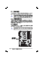
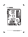
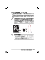
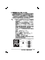
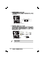
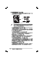
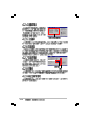
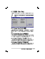
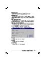
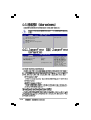
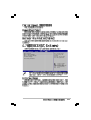
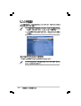
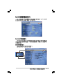
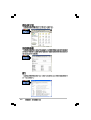
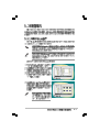
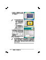
Motherboard
P5VD1-X
T2180
© 2005
2
3
4
5
•
•
•
•
•
•
•
•
•
•
•
•
6
•
•
•
•
•
7
1 2
Jumper Mode
8
2 3
Jumper Free
(Default)
P5GD1-TAYZ
6
10839 11036
0
11XX11XX11
9
®
®
10
11
12
1-1
®
1-2
®
®
®
®
1-3
1-4
SB_PWR
P5VD1-X
®
P5VD1-X Onboard LED
ON
Standby
Power
OFF
Powered
Off
2-1
P5VD1-X
®
2-2
22.9cm( 9.0in)
PS/2KBMS
T: Mouse
B: Keyboard
ATX12V
VIA
PT880Ultra
CPU_FAN
30.5cm (12.0in)
LAN_USB34
EATXPWR
USBPW12
USBPW34
DDR DIMM_B2 (64 bit,184-pin module)
USB12
DDR DIMM_B1 (64 bit,184-pin module)
COM1
DDR DIMM_A2 (64 bit,184-pin module)
DDR DIMM_A1 (64 bit,184-pin module)
LGA775
PARALLEL PORT
SPDIF_O
PRI_IDE
Top:Line In
Center:Line Out
Below:Mic In
SEC_IDE
AGP
Intel
82540EM
CR2032 3V
Lithium Cell
CMOS Power
VIA
VT8237R
P5VD1-X
PCIEX16
®
PCI1
PCI2
CD AUX
PCI3
USBPW56
USBPW78
FP_AUDIO
FLOPPY
Super
I/O
4Mb
BIOS
SB_PWR
AD1888
USB56
USB78
SATA2
SATA1
CHA_FAN
GAME
CLRTC
PANEL
2-3
•
•
•
•
P5VD1-X
®
P5VD1-X CPU Socket 775
2-4
A
B
B
A
2-5
A
B
2-6
®
®
®
•
®
®
•
®
®
•
2-7
B
A
A
A
B
B
A
B
P5VD1-X
®
P5VD1-X CPU Fan connector
2-8
CPU FAN PWM
CPU FAN IN
CPU FAN PWR
GND
CPU_FAN
DIMM_B2
DIMM_B1
DIMM_A2
DIMM_A1
80 Pins
®
104 Pins
P5VD1-X
P5VD1-X 184-pin DDR DIMM sockets
•
•
•
2-9
2-10
2-11
2
1
1
2
1
1
2-12
2-13
A
2-14
B
C
D
E
F
G
H
P5VD1-X
®
Keyed for 1.5v
P5VD1-X Accelerated Graphics Port (AGP)
2-15
2-16
2-17
CLRTC
P5VD1-X
®
1 2
P5VD1-X Clear RTC RAM
2-18
Normal
(Default)
2 3
Clear CMOS
USBPW12
USBPW34
2 3
1 2
+5V
(Default)
+5VSB
USBPW56
USBPW78
P5VD1-X
®
P5VD1-X USB device wake up
1 2
+5V
(Default)
2 3
+5VSB
2-19
1
2
3
4
5
6
11
2-20
10
9
8
7
2-21
FLOPPY
P5VD1-X
R
PIN 1
P5VD1-X
R
PIN 1
P5VD1-X IDE connectors
•
•
2-22
SEC_IDE
PRI_IDE
P5VD1-X Floppy disk drive connector
SATA1
P5VD1-X
®
GND
RSATA_TXP1
RSATA_TXN1
GND
RSATA_RXP1
RSATA_RXN1
GND
SATA2
GND
RSATA_TXP2
RSATA_TXN2
GND
RSATA_RXP2
RSATA_RXN2
GND
P5VD1-X SATA connectors
•
•
2-23
P5VD1-X USB 2.0 connectors
2-24
®
USB56
1
USB+5V
USB_P8USB_P8+
GND
NC
GND
+12V
Rotation
CPU FAN PWM
CPU FAN IN
CPU FAN PWR
GND
®
USB78
1
USB+5V
USB_P7USB_P7+
GND
P5VD1-X
USB+5V
USB_P6USB_P6+
GND
NC
P5VD1-X
USB+5V
USB_P5USB_P5+
GND
CPU_FAN CHA_FAN
P5VD1-X Fan connectors
•
•
•
•
•
•
ATXPWR
+3 Volts
+12 Volts
GND +12V DC
+12 Volts
+5V Standby
Power OK
Ground
GND +12V DC
+5 Volts
Ground
+5 Volts
Ground
+3 Volts
connectors
+3 Volts
ATX12V
P5VD1-X
®
P5VD1-X ATX power
Ground
+5 Volts
+5 Volts
+5 Volts
-5 Volts
Ground
Ground
Ground
PSON#
Ground
-12 Volts
+3 Volts
2-25
CD(Black) AUX(White)
P5VD1-X
®
Left Audio Channel
Ground
Ground
Right Audio Channel
Left Audio Channel
Ground
Ground
Right Audio Channel
+5V
J1B2
J1CY
GND
GND
J1CX
J1B1
+5V
P5VD1-X Internal audio connectors
P5VD1-X
®
P5VD1-X Game connector
2-26
MIDI_IN
J2B2
J2CY
MIDI_OUT
J2CX
J2B1
+5V
GAME
MIC2
MICPWR
Line out_R
NC
Line out_L
P5VD1-X
®
FP_AUDIO
P5VD1-X Front panel audio connector
2-27
BLINE_OUT_L
AGND
+5VA
BLINE_OUT_R
SPEAKER
+5V
Ground
Ground
Speaker
PLED-
PLED+
PLED
®
IDE_LED
Reset
Ground
P5VD1-X
PWR
Ground
IDE_LED+
IDE_LED-
PANEL
RESET
PWRSW
* Requires an ATX power supply.
P5VD1-X System Panel connector
•
•
•
•
•
2-28
3-1
3-2
4-1
EZFlash starting BIOS update
Checking for floppy...
EZFlash starting BIOS update
Checking for floppy...
Floppy found!
Reading file “P5VD1-X.ROM”. Completed.
Start erasing.......|
Start Programming...|
Flashed successfully. Rebooting.
•
•
4-2
•
•
A:\>afudos /oOLDBIOS1.ROM
A:\>afudos /oOLDBIOS1.ROM
AMI Firmware Update Utility - Version 1.10
Copyright (C) 2002 American Megatrends, Inc. All rights reserved.
Reading flash ..... done
A:\>
4-3
A:\>afudos /iP5VD1-X.ROM
A:\>afudos /iP5VD1-X.ROM
AMI Firmware Update Utility - Version 1.10
Copyright (C) 2002 American Megatrends, Inc. All rights reserved.
Reading file ..... done
Erasing flash .... done
Writing flash .... 0x0008CC00 (9%)
A:\>afudos /iP5VD1-X.ROM
AMI Firmware Update Utility - Version 1.10
Copyright (C) 2002 American Megatrends, Inc. All rights reserved.
Reading file ..... done
Erasing flash .... done
Writing flash .... 0x0008CC00 (9%)
Verifying flash .. done
A:\>
4-4
Bad BIOS checksum. Starting BIOS recovery...
Checking for floppy...
Bad BIOS checksum. Starting BIOS recovery...
Checking for floppy...
Floppy found!
Reading file “P5VD1-X.ROM”. Completed.
Start flashing...
4-5
Bad BIOS checksum. Starting BIOS recovery...
Checking for floppy...
Bad BIOS checksum. Starting BIOS recovery...
Checking for floppy...
Floppy not found!
Checking for CD-ROM...
CD-ROM found.
Reading file “P5VD1-X.ROM”. Completed.
Start flashing...
4-6
4-7
4-8
4-9
4-10
System Time
System Date
Legacy Diskette A
Language
Primary IDE Master
Primary IDE Slave
Secondary IDE Master
Secondary IDE Slave
Third IDE Master
Fourth IDE Master
IDE Configuration
System Information
[11:10:19]
[Thu 03/27/2003]
[1.44M, 3.5 in]
[English]
:[ST320413A]
:[ASUS CD-S340]
:[Not Detected]
:[Not Detected]
:[Not Detected]
:[Not Detected]
Use [ENTER], [TAB]
or [SHIFT-TAB] to
select a field.
Use [+] or [-] to
configure system time.
+Tab
F1
F10
ESC
Select Screen
Select Item
Change Field
Select Field
General Help
Save and Exit
Exit
4-11
System Time
System Date
Legacy Diskette A
Language
Primary IDE Master
Primary IDE Slave
Secondary IDE Master
Secondary IDE Slave
Third IDE Master
Fourth IDE Master
IDE Configuration
[11:10:19]
[Thu 03/27/2003]
[1.44M, 3.5 in]
[English]
:[ST320413A]
:[ASUS CD-S340]
:[Not Detected]
:[Not Detected]
:[Not Detected]
:[Not Detected]
System Information
Use [ENTER], [TAB]
or [SHIFT-TAB] to
select a field.
Use [+] or [-] to
configure system time.
+Tab
F1
F10
ESC
Select Screen
Select Item
Change Field
Select Field
General Help
Save and Exit
Exit
+F1
F10
ESC
Select Screen
Select Item
Change Option
General Help
Save and Exit
Exit
Advanced Chipset settings
WARNING: Setting wrong values in the sections below
may cause system to malfunction.
4-12
Configure DRAM Timing by SPD
Memory Acceleration Mode
DRAM Idle Timer
DRAm Refresh Rate
[Enabled]
[Auto]
[Auto]
[Auto]
Graphic Adapter Priority
Graphics Aperture Size
Spread Spectrum
[AGP/PCI]
[ 64 MB]
[Enabled]
ICH Delayed Transaction
[Enabled]
MPS Revision
[1.4]
System
System
Legacy
Legacy
Time
Date
Diskette A
Diskette B
Primary IDE Master
Primary IDE Slave
Third IDE Master
Third IDE Slave
Fourth IDE Master
Fourth IDE Slave
IDE Configuration
[11:51:19]
[Thu 05/07/2004]
[1.44M, 3.5 in]
[Disabled]
: [ST320413A]
: [Not Detected]
: [Not Detected]
: [Not Detected]
: [Not Detected]
: [Not Detected]
System Information
4-13
Primary IDE Master
Device
: Hard Disk
Vendor
: ST320413A
Size
: 20.0GB
LBA Mode
: Supported
Block Mode
: 16 Sectors
PIO Mode
: Supported
Async DMA
: MultiWord DMA-2
Ultra DMA
: Ultra DMA-5
SMART Monitoring: Supported
Type
LBA/Large Mode
Block(Multi-sector Transfer)
PIO Mode
DMA Mode
Smart Monitoring
32Bit Data Transfer
4-14
[Auto]
[Auto]
[Auto]
[Auto]
[Auto]
[Auto]
[Disabled]
AMIBIOS
Version
: 08.00.10
Build Date : 04/07/04
Processor
Type
Speed
Count
: Genuine Intel(R) CPU 3.20GHz
: 2800 MHz
: 1
System Memory
Size
: 512MB
4-15
Configure CPU.
JumperFree Configuration
USB Configuration
CPU Configuration
Chipset
Onboard Devices Configuration
PCI PnP
Configure System Frequency/Voltage
4-16
AI Overclocking Tuner
CPU Frequency
AGP/PCI Frequency
[Manual]
[200]
[Auto]
Spread Spectrum
[OverSpectrum 0.30%]
Select the target CPU
frequency, and the
relevant parameters
will be auto-adjusted.
Frequencies higher
than CPU manufacturer
recommends are not
guaranteed to be
stable. If the system
becomes unstable,
return to the default.
USB Configuration
Module Version - 2.24.0-10.4
USB Devices Enabled:
1 Mouse
USB 1.1 Ports Configuration
USB 2.0 Ports Enable
VIA USB Device Function Enable
Legacy USB Support
Port 64/60 Emulation
USB 2.0 Controller Mode
BIOS EHCI Hand-Off
[USB 8 Ports]
[Enable]
[Disabled]
[Enabled]
[Disabled]
[FullSpeed]
[Enabled]
4-17
Configure Advanced CPU settings
Manufacturer:
Brand String:
Frequency
:
FSB Speed
:
Intel
Genuine Intel(R) CPU 3.20GHz
3200 MHz
800 MHz
Cache L1
: 16 KB
Cache L2
: 1024 KB
Cache L3
: 0 KB
Ratio Status: Unlocked
Ratio Actual Value : 16
Ratio CMOS Setting:
Max CPUID Value Limit:
Hardware Prefetcher
Adjacent Cache Line Prefetch
CPU Internal Thermal Control
Hyper Threading Technology
4-18
[16]
[Disabled]
[Enabled]
[Enabled]
[Auto]
[Disabled]
Sets the ratio between
CPU Core Clock and the
FSB Frequency.
NOTE: If an invalid
ratio is set in CMOS
then actual and
setpoint values may
differ.
+F1
F10
ESC
Select Screen
Select Item
Change Option
General Help
Save and Exit
Exit
Advanced Chipset Settings
Options for VIA PT880U
WARNING: Setting wrong values in below sections may
cause system to malfunction.
NorthBridge VIA PT880Ultra Configuration
SouthBridge VIA VT8237R Configuration
+F1
F10
ESC
DRAM Clock/Timing Configuration
AGP & P2P Bridge Configuration
V-Link & PCI Bus Configuration
Select Screen
Select Item
Change Option
General Help
Save and Exit
Exit
Options for DRAM
+F1
F10
ESC
Select Screen
Select Item
Change Option
General Help
Save and Exit
Exit
4-19
DRAM Frequency
DRAM Timing
DRAM CAS Latency
Precharge to Active(Trp)
Active to Precharge(Tras)
Active to CMD(Trcd)
DRAM BUS Selection
[Auto]
[Manual]
[2.5]
[4T]
[7T]
[4T]
[Auto]
Manual DRAM Frequency
Setting or AUTO by
SPD
+F1
F10
ESC
4-20
Select Screen
Select Item
Change Option
General Help
Save and Exit
Exit
AGP 3.0 Mode
AGP Fast Write
AGP Aperture Size
Primary Graphics Adapter
[8X]
[Enabled]
[128MB]
[PCI Express]
Select Option To Set
AGP MODE
+F1
F10
ESC
V-Link mode selection
V-Link Data 2X Support
[Mode 1]
[Disabled]
Select Screen
Select Item
Change Option
General Help
Save and Exit
Exit
Select V-Link Mode
+F1
F10
ESC
Select Screen
Select Item
Change Option
General Help
Save and Exit
Exit
4-21
PCI Delay Transaction
OnBoard SATA-IDE
RAID BIOS Execute
Onboard AC’97
[Disabled]
[RAID]
[Enabled]
[Enabled]
Options for DRAM
+F1
F10
ESC
4-22
Select Screen
Select Item
Change Option
General Help
Save and Exit
Exit
Configure Win627EHF Super IO Chipset
Serial Port2 Address
Serial Port2 Mode
Parallel Port Address
Parallel Mode
ECP Mode DMA Channel
Parallel Port IRQ
OnBoard Game.MIDI Port
[2F8/IRQ3]
[Normal]
[378]
[ECP]
[DMA3]
[IRQ7]
[Disabled]
OnBoard LAN
Onboard LAN Boot ROM
[Enabled]
[Disabled]
Allow BIOS to Select
Serial Port2 Base
Addresses.
4-23
Advanced PCI/PnP Settings
WARNING: Setting wrong values in below sections
may cause system to malfunction.
4-24
Plug And Play O/S
PCI Latency Timer
Allocate IRQ to PCI VGA
Palette Snooping
[No]
[64]
[Yes]
[Disabled]
IRQ-3 assigned to
IRQ-4 assigned to
IRQ-5 assigned to
IRQ-7 assigned to
IRQ-9 assigned to
IRQ-10 assigned to
IRQ-11 assigned to
IRQ-14 assigned to
IRQ-15 assigned to
[PCI
[PCI
[PCI
[PCI
[PCI
[PCI
[PCI
[PCI
[PCI
Device]
Device]
Device]
Device]
Device]
Device]
Device]
Device]
Device]
+F1
F10
ESC
Select Screen
Select Item
Change Option
General Help
Save and Exit
Exit
Suspend Mode
ACPI 2.0 Support
ACPI APIC Support
[S1 (POS) only]
[No]
[Enabled]
Configure CPU.
APM Configuration
Hardware Monitor
4-25
4-26
Power Management
[Enabled]
Power Button Mode
Restore on AC Power Lose
[On/Off]
[Last State]
Advanced Resume Events Control
Resume on Ring
Resume on PME#
Resume on KB
Wake-Up Key
Resume on By PS/2 Mouse
Resume on RTC Alarm
[Disabled]
[Disabled]
[Disabled]
[Any Key]
[Disabled]
[Disabled]
Enabled or disable
APM.
Hardware Monitor
CPU Temperature
CPU Temperature
MB Temperature
[48ºC/118.5ºF]
[32ºC/89.5ºF]
CPU Fan Speed
CPU Q-Fan Control
CPU Target Temperature
Chassis Fan Speed
[2393 RPM]
[Disabled]
[50° C]
[N/A]
VCORE Voltage
3.3V Voltage
5V Voltage
12V Voltage
[ 1.376V]
[ 3.296V]
[ 5.208V]
[11.510V]
+F1
F10
ESC
Select Screen
Select Item
Change Option
General Help
Save and Exit
Exit
4-27
4-28
APM Configuration
Boot Device Priority
Boot Settings Configuration
Security
Enter
F1
F10
ESC
Select Screen
Select Item
Go to Sub-screen
General Help
Save and Exit
Exit
Boot Device Priority
1st Boot Device
2nd Boot Device
3rd Boot Device
[1st FLOPPY DRIVE]
[PM-ST330620A]
[PS-ASUS CD-S360]
4-29
Boot Settings Configuration
Quick Boot
Full Screen Logo
AddOn ROM Display Mode
Bootup Num-Lock
PS/2 Mouse Support
Wait For ‘F1’ If Error
Hit ‘DEL’ Message Display
Interrupt 19 Capture
4-30
[Enabled]
[Enabled]
[Force BIOS]
[On]
[Auto]
[Enabled]
[Enabled]
[Disabled]
Allows BIOS to skip
certain tests while
booting. This will
decrease the time
needed to boot the
system.
Security Settings
Supervisor Password
User Password
: Not Installed
: Not Installed
<Enter> to change
password.
<Enter> again to
disabled password.
Change Supervisor Password
Boot Sector Virus Protection
[Disabled]
4-31
Security Settings
Supervisor Password
User Password
4-32
: Not Installed
: Not Installed
Change Supervisor Password
User Access Level
Change User Password
Clear User Password
Password Check
[Setup]
Boot Sector Virus Protection
[Disabled]
[Full Access]
Select Screen
Select Item
Exit Options
Exit & Save Changes
Exit & Discard Changes
Discard Changes
Load Setup Defaults
Exit system setup
after saving the
changes.
F10 key can be used
for this operation.
Enter
F1
F10
ESC
Select Screen
Select Item
Go to Sub-screen
General Help
Save and Exit
Exit
4-33
4-34
5-1
5-2
5-3
5-4
5-5
5-6
5-7
5-8
5-9
VIA Tech. RAID BIOS Ver 1.xx
Auto Setup For Data Security
Array Mode RAID 1 (Mirroring)
Select Disk Drives
Start Create Process
Create a RAID array with
the hard disks attached to
VIA RAID controller
F1
↓
↑,↓
Enter
ESC
Channel
5-10
Drive Name
:
:
:
:
View Array/Disk Status
Move to next item
Confirm the selection
Exit
Array Name Mode
Size(GB) Status
Serial_Ch0 Master XXXXXXXXXXX
ARRAY 0
SATA
999.99
XXXXXXX
Serial_Ch1 Master XXXXXXXXXXX
ARRAY 0
SATA
999.99
XXXXXXX
RAID 0 for performance
RAID 1 for Data Protection
RAID SPAN for capacity
Auto create array will destroy all
data on disks, Continue? (Y/N)
4K
8K
16K
32K
64K
The data on the selected disks will
be destroyed. Continue? Press Y/N
5-11
RAID 0 for performance
RAID 1 for Data Protection
RAID 0/1
RAID SPAN for capacity
Auto create array will destroy all
data on disks, Continue? (Y/N)
Save the data on source disk to
mirror after creation? (Y/N)
D u p l i c a t i n g . . . . .
RAID 1 for data protection
Press Yes(Y) to Escape
The data on the selected disks will
be destroyed. Continue? (Y/N)
5-12
5-13
5-14