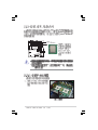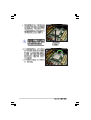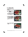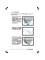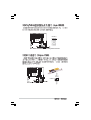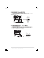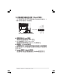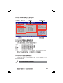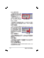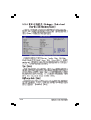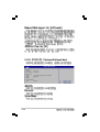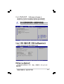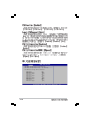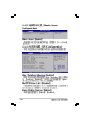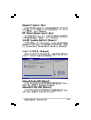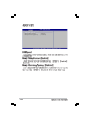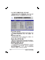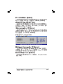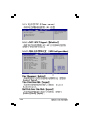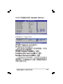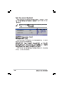
1
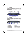
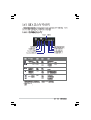
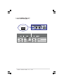
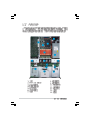
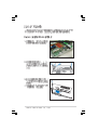
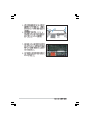
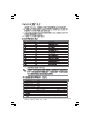
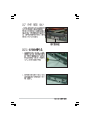
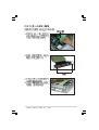
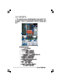
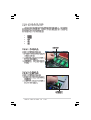
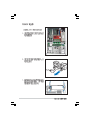
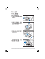
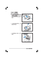
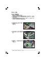
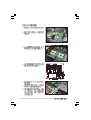
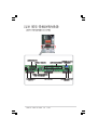
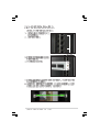
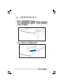
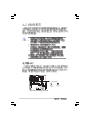
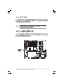
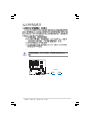
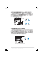
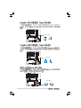
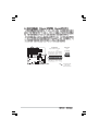
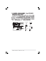
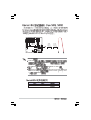
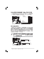
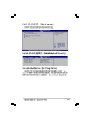
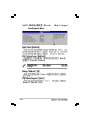
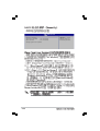
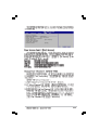
®
AP1600R-E2(CS3)
®
ASUSPRO 1600R-E2(CS3)
Intel Xeon Pentium
Windows MS-DOS
Intel
Microsoft
©2005
2
3
4
5
6
IC
7
UPS
IC
8
9
10
1-2
®
1U (R11 EVERCASE)
NCL-DS1R1
Intel® Lindenhurst
Intel® ICH5R
Intel® Xeon Nocona
L2 1M
8 184-pin
ECC non-ECC DDR
PC2700 registered
16GB
LAN
Broadcom® BCM5721 Gigabit LAN
Broadcom® BCM5721 Gigabit LAN
VGA
ATI RAGE-XL PCI-based VGA
I/O
I/O
1
64-bit/133MHz 3.3V PCI-X
3
3.5
USB 2.0
Location
Location
Reset
LAN
1 x PS/2
1x
2 x Gigabit LAN
Location
Web
Message
1 x PS/2
1 x VGA
2 x USB 2.0
ASWM
Automatic
System Restart, ASR
500W
445mm
x 670mm
x 43.6 mm
1-3
1M
AP1600R-E2(CS3) 1U
Intel® Xeon
L2
800MHz
8 PC2700 DDR
16 GB
Gigabit
8MB ATI RAGE-XL VGA
AP1600R-E2(CS3)
Microsoft Windows® Server 2003
®
Enterprise Edition Windows Server 2003 Standard Edition Windows®
2003 for Small Business Server(CHT) Windows® 2003 for Small Business
Server(ENG) Windows® 2000 Advance Server RedHat Linux® Enterprise
Server Advance Server 3.0 SuSE Linux® Enterprise Server 8.0 Novell
Netware 6.5
AP1600R-E2(CS3)
19
AP1600R-E2(CS3)
LED
1U
1-4
1-5
LED
Location
Location
OFF
*,**
OFF
LAN1
LAN2
OFF
*
**
1-6
ASWM
FPB AR14
RJ-45
ACT/LNK
SPEED
ACT/LINK LED
SPEED LED
OFF
OFF
10Mbps
100Mbps
1000Mbps
1-7
1-8
1.
2.
3.
4.
5.
2-2
2-3
2-4
®
Gold Arrow
Pin A1
NCL-DS1R1
®
Intel Xeon
NCL-DS1R1 CPU Socket 604
1.
2.
CPU
CPU
CPU
1
2-5
2-6
CPU
2-7
104 Pins
80 Pins
DIMM_B4
NCL-DS1R1
®
DIMM_A4
DIMM_B3
DIMM_A3
DIMM_B2
DIMM_A2
DIMM_B1
DIMM_A1
NCL-DS1R1 184-pin DDR DIMM sockets
1.
CL CAS-Latency
2.
2GB
3.
4.
2-8
16GB
A4 B4
DDR DIMM
2-9
3
2
1
2
3
2-10
1
2
3
4
1
2-11
4
3
2-12
2
1
PCI
IRQ
ICH5 IDE Controller
ICH5 SATA Controller
ICH5 SMBus Controller
ICH5 USB UHCI Controller #1
ICH5 USB UHCI Controller#2
ICH5 USB 2.0 EHCI Controller
AIC7902
Zero Channel RAID Socket
ATI RAGE XL
PCI
PCI-X
1
IRQ
INTA
PIRQC#
PIRQC#
PIRQB#
PIRQA#
PIRQD#
PIRQH#
PXH2_A_0
PXH2_A_2
PIRQB#
INTB
PXH2_A_1
-
INTC
-
PXH1_B_0 PXH1_B_1 PXH1_B_2
IRQ
INTD
-
REQ#
PXH2_A_0
PXH2_A_1
REQ1#
GNT#
PXH2_A_0
PXH2_A_1
GNT1#
PXH1_B_3 PXH1_B_0
PXH1_B_0
2-13
2-14
2-15
2
3
1
5
4
6
7
9
8
13
10
11
14 15 12
1.
2.
3.
4.
5.
6.
7.
8.
9.
10.
11.
12.
13.
14.
15.
2-16
PCI-X
24-pin SSI
8-pin SSI
I2C 5-pin
SCSI
IDE
(
)
(
)
(SCSI
)
(
)
(
)
(
)
(
(
4-pin
LED
SMBus
LED
USB
)
)
1.
2.
3.
4.
5.
2-17
2
1
2-18
1
22
1
1
1
2
25
14
12
2-19
5
4
2
1
1
2-20
2-21
2-22
NCL-DS1R1
®
2-23
1
1
2
2
2-24
3-2
3-3
3-4
1.
2.
3.
4.
5.
ATX
OFF
SB_PWR1
NCL-DS1R1
®
/
ON
Standby
Power
NCL-DS1R1 Standby power LED
4-2
OFF
Powered
Off
4-3
NCL-DS1R1
®
33cm (13in)
REAR_FAN2
USB1
USB2
ATX12V1
PSUSMB1
CPU_FAN1
DDR DIMM_B4 (64/72 bit, 184-pin module)
USBPW12
DDR DIMM_A4 (64/72 bit, 184-pin module)
mPGA 604
T: Mouse
B: Keyboard
ATXPWR1
KBPWR1
PS/2
FM_CPU1
COM1
DDR DIMM_B3 (64/72 bit, 184-pin module)
DDR DIMM_A3 (64/72 bit, 184-pin module)
DDR DIMM_B2 (64/72 bit, 184-pin module)
DDR DIMM_A2 (64/72 bit, 184-pin module)
®
VGA
DDR DIMM_B1 (64/72 bit, 184-pin module)
Broadcom
BCM5721
Intel E7520
MCH
RJ-45
(LAN-2)
RECPVERY1
Broadcom
BCM5721
LAN1_EN1
J2
SEC_IDE
CPU_FAN2
LAN2_EN1
AMI
8Mb
FWH
DSW1
PCIX1 (64-bit, 133MHz 3V)
FM_CPU2
PRI_IDE
Intel
PXH
Super
I/O
SATA2
SATA1
Intel
ICH5R
FRNT_FAN1
FRNT_FAN2
VGA_EN1
USBPW34
ATI
RAGE XL
VGA
Controller
CR2032 3V
Lithium Cell
CMOS Power
BPSMB1
FLOPPY1
BUZZ1
CLRTC1
AUX_PANEL1
SB_PWR1
4-4
COM2
BMCCONN1
Intel
PXH
Adaptec
AIC-7902W
SCSIB1
HDLED1
USB34
SCSI_EN1
PANEL1
34
1
68
35
SCSIA1
30.5cm (12in)
REAR_FAN1
RJ-45
(LAN-1)
NCL-DS1R1
mPGA 604
DDR DIMM_A1 (64/72 bit, 184-pin module)
®
NCL-DS1R1
CLRTC1
2 1
NCL-DS1R1 Clear RTC RAM
Normal
(Default)
3 2
Clear CMOS
4-5
USBPW12
1 2
2 3
+5VSB
NCL-DS1R1
®
+5V
(Default)
USBPW34
1
2
+5V
(Default)
NCL-DS1R1 USB device wake up
1.
USB
2
3
+5VSB
+5VSB
500mA/+5VSB
2.
+5VSB
WIndows 2000
Service Pack 4.0
S4
NCL-DS1R1
®
3.
VGA_EN1
1
2
NCL-DS1R1 VGA setting
4-6
Enable
(Default)
2
3
Disable
FM_CPU1
3
2
NCL-DS1R1
®
2
1
DC mode
(Default)
PWM
FM_CPU2
3
2
2
1
DC mode
(Default)
NCL-DS1R1 FM_CPU setting
PWM
KBPWR1
NCL-DS1R1
®
1
2
+5V
(Default)
2
3
+5VSB
NCL-DS1R1 Keyboard power setting
4-7
®
NCL-DS1R1
LAN1_EN1
2
1
Enable
(Default)
3
2
Disable
NCL-DS1R1
®
NCL-DS1R1 LAN1_EN setting
LAN2_EN1
2
1
Enable
(Default)
3
2
Disable
NCL-DS1R1
®
NCL-DS1R1 LAN2_EN setting
SCSI_EN1
1 2
Enable
(Default)
NCL-DS1R1 SCSI setting
4-8
2 3
Disable
®
NCL-DS1R1
RECOVERY1
1 2
2 3
Normal
(Default)
BIOS Recovery
NCL-DS1R1 BIOS recovery setting
1 2 3 4 5
ON
NCL-DS1R1
1 2 3 4 5
DDR 333 setting
ON
®
DSW1
DDR 266 setting
NCL-DS1R1 CPU external frequency selection
4-9
1
2
3
4
ACT/LINK LED
OFF
5
SPEED LED
OFF
6
ACT/LINK SPEED
LED
LED
10Mbps
100Mbps
1000Mbps
LAN ≥s±µ∫›§f
4-10
NCL-DS1R1
®
IDE
FLOPPY1
PIN 1
NOTE: Orient the red markings on
the floppy ribbon cable to PIN 1.
NCL-DS1R1 Floppy disk drive connector
NCL-DS1R1
®
COM2
PIN 1
NCL-DS1R1 Serial port connectors
4-11
1.
UltraDMA
UltraDMA/100/66
SEC_IDE
PIN 1
NCL-DS1R1
®
2.
IDE
PRI_IDE
PIN 1
NCL-DS1R1 IDE connectors
NOTE: Orient the red markings
(usually zigzag) on the IDE
ribbon cable to PIN 1.
UltraDMA/100/66 IDE
80
4-12
IDE
UltraDMA/100/66
80
IDE
NCL-DS1R1 SMBus connector
GND
I2C_6_DATA#
+5V
FAN_DC
I2C_6_CLK#
NCL-DS1R1
®
PSUSMB1
NCL-DS1R1 Power supply SMBus connector
BPSMB1
1
4-13
NCL-DS1R1
®
I2C_7_CLK#
I2C_7_DATA#
NC
GND
+3.3V Remote Sense
NCL-DS1R1 ATX power connectors
4-14
+3 Volts
-12 Volts
Ground
PSON#
Ground
Ground
Ground
-5 Volts
+5 Volts
+5 Volts
+5 Volts
Ground
12V
12V
12V
12V
NCL-DS1R1
®
GND
GND
GND
GND
+3 Volts
+3 Volts
Ground
+5 Volts
Ground
+5 Volts
Ground
Power OK
+5V Standby
+12 Volts
+12 Volts
+3 Volts
ATXPWR1
ATX12V1
24-pin Power Connector
8-pin
For Power Supply
with 24-pin
Power Connector
NCL-DS1R1
®
REAR_FAN1
CPU_FAN2
PWM Control
FAN Speed
FAN Power
GND
REAR_FAN2
CPU_FAN1
GND
FAN Power
FAN Speed
PWM Control
CPU_FAN1
CPU_FAN2
FRNT_FAN1
FRNT_FAN2
REAR_FAN1
GND
+12V
Rotation
FRNT_FAN1
NCL-DS1R1 Fan connectors
GND
+12V
Rotation
REAR_FAN2
Rotation
+12V
GND
FRNT_FAN2
GND
+12V
Rotation
4-15
GND
RSATA_RXP2
RSATA_RXN2
GND
RSATA_TXN2
RSATA_TXP2
GND
GND
RSATA_RXP1
RSATA_RXN1
GND
RSATA_TXN1
RSATA_TXP1
GND
®
NCL-DS1R1
SATA2
SATA1
NCL-DS1R1 SATA connectors
Serial ATA
Serial ATA
Serial ATA
Parallel ATA
RAID 0
RAID1
Serial ATA RAID
Serial ATA
Windows XP Service Pack 1
2000 Service Pack 4
1
Windows
SATA1
SATA2
4-16
Master
Slave
Serial ATA RAID
RAID 0
Windows
RAID
SCSIB1
68-Pin Ultra320/
Ultra2-Wide SCSI Connector
NCL-DS1R1
®
1 35
SCSIA1
68-Pin Ultra320/
Ultra2-Wide SCSI Connector
34
68
34 68
1
35
NCL-DS1R1 Onboard SCSI connectors
SCSI
SCSI
Ultra320 Ultra160 Ultra2
SCSI
SCSI
Ultra-Wide
68-pin Internal SCSI Cable (Twisted-Pair Ribbon)
NCL-DS1R1
®
Channel A
Internal SCSI Devices (up to 15 devices)
68-pin Female
Terminator
68-pin Internal SCSI Cable (Twisted-Pair Ribbon)
Channel B
Internal SCSI Devices (up to 15 devices)
68-pin Female
Terminator
NCL-DS1R1 SCSI connection example
4-17
NCL-DS1R1 USB connector
4-18
NC
GND
USB PortB(+)
USB PortB(-)
Power
®
GND
USB PortA(+)
USB PortA(-)
Power
NCL-DS1R1
®
SCSI_ACTLED+
SCSI_ACTLEDSCSI_ACTLEDSCSI_ACTLED+
NCL-DS1R1
HDLED1
1
NCL-DS1R1 SCSI/SATA card activity LED connector
USB34
1
POWERLED+
NC
POWERLEDMLED+
MLEDNC
+5V
GND
GND
SPKROUT
®
+5VSB
+5VSB
BMC SMBDATA
12CDATA1
FP_PWRBTN#
BMC_PRESENT#
BMC_SMI#
GND
NCL-DS1R1 BMC connector
NCL-DS1R1 System panel connector
NMIBTN#
GND
POWERBTN#
GND
NC
RESETBTN#
GND
HDLED+
HDLED-
NCL-DS1R1
NCL-DS1R1
BMCCONN1
PANEL1
4-19
®
+5VSB
+5VSB
BMC SMBCLK
12CCLK1
PSON#
BMC_RST#
PWROK
PSONEN#
4-20
NCL-DS1R1 Auxiliary panel connector
+5VSB
PIN1
CASEOPEN
GND
LOCATORLED1+
LOCATORLED1LOCATORBTN#
GND
LOCATORLED2LOCATORLED2+
AUX_PANEL1
4-21
®
GND
I2C_4_DATA#
+5VSB
LAN1_LINKACTLED+
LAN1_LINKACTLEDLAN2_LINKACTLEDLAN2_LINKACTLED+
NC
I2C_4_CLK#
NCL-DS1R1
4-22
BIOS
BIOS
BIOS
DOS
Windows XP
Windows 2000
5-2
AFUDOS
BIOS
600KB
BIOS
A:\>afudos /oOLDBIOS1.ROM
A:\>afudos /oOLDBIOS1.ROM
AMI Firmware Update Utility - Version 1.10
Copyright (C) 2002 American Megatrends, Inc. All rights
reserved.
Reading flash ..... done
A:\>
5-3
BIOS
A:\>afudos /iNCL-DS1.ROM
A:\>afudos /iNCL-DS1.ROM
AMI Firmware Update Utility - Version 1.10
Copyright (C) 2002 American Megatrends, Inc. All rights reserved.
Reading file ..... done
Erasing flash .... done
Writing flash .... 0x0008CC00 (9%)
BIOS
A:\>afudos /iNCL-DS1.ROM
AMI Firmware Update Utility - Version 1.10
Copyright (C) 2002 American Megatrends, Inc. All rights reserved.
Reading file ..... done
Erasing flash .... done
Writing flash .... 0x0008CC00 (9%)
Verifying flash .. done
A:\>
5-4
1.
BIOS
BIOS
2.
BIOS
NCLDS1R1.ROM
Bad BIOS checksum. Starting BIOS recovery...
Checking for floppy...
Bad BIOS checksum. Starting BIOS recovery...
Checking for floppy...
Floppy found!
Reading file “NCLDS1R1.ROM”. Completed.
Start flashing...
BIOS
5-5
Bad BIOS checksum. Starting BIOS recovery...
Checking for floppy...
Bad BIOS checksum. Starting BIOS recovery...
Checking for floppy...
Floppy not found!
Checking for CD-ROM...
CD-ROM found.
Reading file “NCLDS1R1.ROM”. Completed.
Start flashing...
BIOS
BIOS
http://www.asus.com.cn
5-6
BIOS
BIOS
ISP
BIOS
5-7
5-8
BIOS
5-9
1. BIOS
BIOS
2.
BIOS
BIOS
3.
Load Setup Defaults
http://www.asus.com.cn
BIOS
5-10
2.7
BIOS
System Time
System Date
Legacy Diskette A
Primary IDE Master
Primary IDE Slave
Third IDE Master
Third IDE Slave
Fourth IDE Master
Fourth IDE Slave
IDE Configuration
[11:10:19]
[Fri 08/06/2004]
[1.44M, 3.5 in]
:
:
:
:
:
:
[ST320413A]
[ASUS CD-S520/A]
[Not Detected]
[Not Detected]
[Not Detected]
[Not Detected]
Use [ENTER], [TAB] or
[SHIFT-TAB] to select
a field.
Use [+] or [-] to
configure the System
time.
System Information
5-11
System Time
[11:51:19]
System Date
[Thu 05/07/2004]
Legacy Diskette A
[1.44M, 3.5 in]
Primary IDE Master : [ST320413A]
Primary IDE Slave : [ASUS CD-S520/A
Third IDE Master : [Not Detected]
Third IDE Slave
: [Not Detected]
Fourth IDE Master : [Not Detected]
Fourth IDE Slave : [Not Detected]
IDE Configuration
System Information
Advanced PCI/PnP Settings
WARNING: Setting wrong values in
below sections may cause system to
malfunction.
Plug And Play O/S
PCI Latency Timer
Allocate IRQ to PCI VGA
Palette Snooping
PCI IDE BusMaster
5-12
[No]
[64]
[Yes]
[Disabled]
[Enabled]
Use [ENTER],
[TAB] or [SHIFTTAB] to select a
field.
Use [+] or [-] to
configure the
System time.
5.2.1 BIOS
System Time
System Date
Legacy Diskette A
Primary IDE Master
Primary IDE Slave
Third IDE Master
Third IDE Slave
Fourth IDE Master
Fourth IDE Slave
IDE Configuration
[11:10:19]
[Fri 08/06/2004]
[1.44M, 3.5 in]
:
:
:
:
:
:
[ST320413A]
[ASUS CD-S520/A]
[Not Detected]
[Not Detected]
[Not Detected]
[Not Detected]
Use [ENTER], [TAB] or
[SHIFT-TAB] to select
a field.
Use [+] or [-] to
configure the System
time.
System Information
5-13
Primary IDE Master
Device
Vendor
Size
LBA Mode
Block Mode
PIO Mode
Async DMA
Ultra DMA
SMART Monitoring
:
:
:
:
:
:
:
:
:
Hard Disk
ST320413A
20.0GB
Supported
16 Sectors
Supported
MultiWord DMA-2
Ultra DMA-5
Supported
Type
[Auto]
LBA/Large Mode
[Auto]
Block(Multi-sector Transfer)[Auto]
PIO Mode
[Auto]
DMA Mode
[Auto]
Smart Monitoring
[Auto]
32Bit Data Transfer
[Disabled]
5-14
Select the type of
device connected to
the system.
IDE Configuration
Onboard IDE Operate Mode
Enhanced Mode Support On
Configure S-ATA as RAID
IDE Detect Time Out (Sec)
[Enhanced Mode]
[S-ATA]
[No]
[35]
When in AHCI/RAID
mode SATA controller
is forced to Native
mode.
5-15
AMIBIOS
Version
: 08.00.10
Build Date : 07/23/04
Processor
Type
Speed
Count
: Intel(R) Xeon(TM) CPU 2.80GHz
: 2800 MHz
: 2
System Memory
Size
: 512MB
5-16
USB Configuration
MPS Configuration
Remote Access Configuration
Configure the USB
support.
CPU Configuration
Chipset
Onboard Devices Configuration
PCI PnP
USB Configuration
Enables USB host
controllers.
Module Version - 2.23.2-5.3
USB Devices Enabled: None
USB Function
Legacy USB Support
USB 2.0 Controller
USB 2.0 Controller Mode
[8 USB Ports]
[Auto]
[Enabled]
[HiSpeed]
USB Mass Storage Device Configuration
5-17
USB Mass Storage Device Configuration
USB Mass Storage Reset Delay
[20 Seconds]
No USB Mass Storage device detected
Device #1
Emulation
Device #2
Emulation
Device #3
Emulation
Device #4
Emulation
Device #5
Emulation
Device #6
Emulation
5-18
Type
Type
Type
Type
Type
Type
N/A
[N/A]
N/A
[N/A]
N/A
[N/A]
N/A
[N/A]
N/A
[N/A]
N/A
[N/A]
5.2.1 BIOS
MPS Configuration
MPS Revision
[1.4]
Enables USB host
controllers.
5-19
Configure Remote Access type and parameters
Remote Access
[Enabled]
Configure Advanced CPU settings
Manufacturer:
Brand String:
Frequency
:
FSB Speed
:
Intel
Intel(R) Xeon (TM) CPU 2.80GHz
2800 MHz
800 MHz
Ratio Status: Unlocked
5-20
Ratio Actual Value : 14
Hyper Threading Technology
Max CPUID Value Limit:
[Enabled]
[Disabled]
Excute Disable Function
Enhanced C1 Control
CPU Internal Thermal Control
Intel(R) Speedstep(tm) Tech
[Enabled]
[Auto]
[Auto]
[Automatic]
Enables USB host
controllers.
Sets the ratio between
CPU Core Clock and the
FSB Frequency.
NOTE: If an invalid
ratio is set in CMOS
then actual and
setpoint values may
differ.
Advanced Chipset Settings
Warning: Setting wrong values in below sections may
cause system to malfunction.
NorthBridge Configuration
Onboard LAN Boot ROM
Onboard SCSI Boot ROM
Enable or disable
DRAM timing.
[Enabled]
[Enabled]
5-21
NorthBridge Chipset Configuration
DIMM Speed: DDR 333
Memory Remap Feature
Memory Mirroring/Sparing
5-22
[Enabled]
[Disabled]
Configure Win627EHF Super IO Chipset
Serial Port1 Address
Serial Port2 Address
Serial Port2 Mode
Enable or disable
Azalia controller.
[3F8/IRQ4]
[2F8/IRQ3]
[Normal]
5-23
Advanced PCI/PnP Settings
WARNING: Setting wrong values in below sections
may cause system to malfunction.
Plug And Play O/S
[No]
PCI Latency Timer
[64]
Allocate IRQ to PCI VGA
[Yes]
Palette Snooping
[Disabled]
PCI IDE BusMaster
[Enabled]
OffBoard PCI/ISA IDE Card
[Auto]
IRQ-3 assigned to
[PCI Device]
IRQ-4 assigned to
[PCI Device]
IRQ-5 assigned to
[PCI Device]
IRQ-7 assigned to
[PCI Device]
IRQ-9 assigned to
[PCI Device]
IRQ-10 assigned to
[PCI Device]
IRQ-11 assigned to
[PCI Device]
IRQ-14 assigned to
[PCI Device]
5-24
NO: Lets the BIOS
configue all the
devices in the system.
YES: Lets the
operating system
configure Plug and
Play (PnP) devices not
required for boot if
your system has a Plug
and Play operating
system.
IRQ-15 assigned to
DMA
DMA
DMA
DMA
DMA
DMA
Channel
Channel
Channel
Channel
Channel
Channel
0
1
3
5
6
7
Reserved Memory Size
[PCI Device]
[PCI
[PCI
[PCI
[PCI
[PCI
[PCI
Device]
Device]
Device]
Device]
Device]
Device]
[Disabled]
5-25
ACPI APIC Support
[Enabled]
Select the ACPI state
used for System
Suspend.
APM Configuration
Hardware Monitor
APM Configuration
5-26
Power Management/APM
Video Power Down Mode
Hard Disk Power Down Mode
Suspend Time Out
Throttle Slow Clock Ratio
[Enabled]
[Disabled]
[Disabled]
[Disabled]
[50%]
Power Button Mode
Restore on AC Power Loss
[On/Off]
[Last State]
Power
Power
Power
Power
Power
[Disabled]
[Disabled]
[Disabled]
[Disabled]
[Disabled]
On
On
On
On
On
By PS/2 Keyboard
By PS/2 Mouse
Ring
By PME#
By RTC Alarm
<Enter> to select
whether or not to
restart the system
after AC power loss.
5-27
5-28
Hardware Monitor
CPU1 Temperature
CPU2 Temperature
MB Temperature
[55ºC/131ºF]
[N/A]
[52ºC/125.5ºF]
CPU1 Fan Speed
CPU2 Fan Speed
Front1 Fan Speed
Front2 Fan Speed
Rear1 Fan Speed
Rear2 Fan Speed
[5487 RPM]
[N/A]
[N/A]
[N/A]
[N/A]
[N/A]
Smart Fan Control
[Disabled]
VCORE1 Voltage
VCORE2 Voltage
3.3V Voltage
5V Voltage
5VSB Voltage
[ 1.320V]
[N/A]
[ 3.296V]
[ 5.070V]
[ 4.992V]
VBAT Voltage
12V Voltage
[ 3.152V]
[12.099V]
5-29
Smart Fan Control
[Enabled]
ture Front1 Temperature
5-30
Smart Fan Control
CPU1 Temperature
CPU2 Temperature
MB Temperature
[Enabled]
[055]
[055]
[050]
VCORE1 Voltage
VCORE2 Voltage
[ 1.356V]
[ 1.358V]
CPU1 Temperature CPU2 Tempera-
APM Configuration
Specifies the Boot
Device Priority
sequence
Boot Device Priority
Boot Settings Configuration
Security
Boot Device Priority
1st
2nd
3rd
4th
Boot
Boot
Boot
Boot
Device
Device
Device
Device
[1st FLOPPY DRIVE]
[PM-ST330620A]
[PS-ASUS CD-S360]
[MBA v7.5.12 Slot 0]
5-31
Boot Settings Configuration
Quick Boot
Full Screen Logo
Bootup Num-Lock
PS/2 Mouse Support
Wait For ‘F1’ If Error
Hit ‘DEL’ Message Display
Interrupt 19 Capture
[Enabled]
[Enabled]
[On]
[Auto]
[Enabled]
[Enabled]
[Enabled]
MyLogo TM
[Enabled]
5-32
Allows BIOS to skip
certain tests while
booting. This will
decrease the time
needed to boot the
system.
Full Screen Logo
5-33
Security Settings
Supervisor Password
User Password
<Enter> to change
password.
<Enter> again to
disabled password.
: Not Installed
: Not Installed
Change Supervisor Password
BIOS
3.3
5-34
CMOS
RTC
Security Settings
Supervisor Password
User Password
: Installed
: Not Installed
Change Supervisor Password
User Access Level
Change User Password
Clear User Password
Password Check
[Full Access]
[Setup]
5-35
Exit Options
Exit & Save Changes
Exit & Discard Changes
Discard Changes
Load Setup Defaults
Esc
F10
5-36
BIOS
BIOS
BIOS
now?
BIOS
[Yes]
Esc
BIOS
Discard configuration changes and exit
BIOS
[No]
5-37
5-38