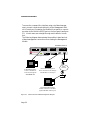
1
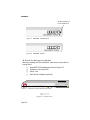
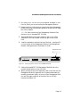
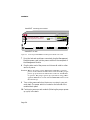
AF 100 NMM cover Page 1 Tuesday, August 20, 1996 4:01 PM
AsantéFAST 100
Management Module
Installation Guide
and User Manual
Table of Contents
Introduction ................................................................ 1-1
The AsantéFAST 100 Management Module .......................... 1-1
Features ................................................................................ 1-2
Package Contents ................................................................. 1-2
Installation .................................................................. 2-1
Installation Overview ........................................................... 2-1
Placement of the Management Module................................ 2-1
Installing the Management Module ...................................... 2-2
Command Line Interface............................................ 3-1
In-Band Management............................................................ 3-1
Out-of-Band Management ..................................................... 3-1
Using the Command Line Interface...................................... 3-3
Main Menu............................................................................ 3-3
Accessing a Submenu ........................................................... 3-3
Exiting a Submenu................................................................ 3-4
General Information Screen ................................................. 3-4
Configuration Main Menu..................................................... 3-5
Configure System Administration Information................ 3-6
Configure Out-of-Band Parameters.................................. 3-7
Configure TCP/IP Parameters.......................................... 3-7
i
Configure Bootstrap Parameters ..................................... 3-8
Configure SNMP Parameters ......................................... 3-10
Configure Port Parameters ............................................ 3-11
Node Summary Display................................................. 3-13
Set Telnet Idle Time Out ................................................ 3-14
Set Console Password ................................................... 3-15
Reset EEProm to Default ............................................... 3-16
Reset System ................................................................. 3-16
Statistics Menu.................................................................... 3-17
Display Segment Counters............................................ 3-17
Display Group Counters ............................................... 3-19
Display Port Counters ................................................... 3-21
Technical Specifications .............................................A-1
Technical Support .......................................................B-1
Index ..................................................................... Index-i
ii
1
Introduction
The AsantéFAST 100 Management Module
Thank you for purchasing the AsantéFAST 100 Management Module, an external addition to the existing unmanageable AsantéFAST
100 Hub.
The AsantéFAST 100 Management Module adds SNMP intelligence
to the AsantéFAST 100 hub or hub stack, enabling the stack to be
managed through the module’s own built-in command line interface via terminal, Telnet, AsantéView network management software, or any other SNMP-compatible network management
software.
A single module is capable of managing an entire stack of 100BASET hubs on a per-stack, per-hub, per-port basis, allowing you to get a
pulse on your network’s performance, traffic, bottlenecks, collisions and other network vital signs. Management capabilities are
extended from the managed unit to all attached hubs (up to 14 in a
stack), providing complete management for up to 168 ports.
Utilization
Low
High
100
Figure 1-1 AsantéFAST
The AsantéFAST 100
Management Module
Sharing the AsantéFAST 100 Hub’s design and expansion card technology, the Management Module fully integrates with the highspeed backplane of the hub — the interconnected hub stack can
then be managed as a single logical repeater.
Page 1-1
Introduction
Features
❏
❏
❏
❏
❏
❏
❏
❏
Monitors a Fast Ethernet network, providing current network information such as data flow, port
utilization, station information and enhanced security features
Gathers data traffic statistics on a per-stack, perhub, per-port basis, providing collision detection,
link tests, relocking, and retiming
Provides instant MAC address-to-IP address mapping — locate and isolate a faulty system instantaneously
Contains a front panel LED bargraph display for
network utilization and collision
Contains two DB-9 and RS232 ports for both console connection and modem connection
Complies with MIB I, MIB II, and RFC 1516
Repeater MIB standard specifications
Built-in SNMP and TCP/IP support — easily integrates into the existing network management environment
Supports up to 168 ports, or 14 stackable AsantéFAST 100 Fast Ethernet hubs
Package Contents
❏
❏
❏
❏
❏
❏
❏
Page 1-2
AsantéFAST 100 Management Module
README FIRST sheet
Installation Guide / User Manual
Registration Card
Power Cord
Rack Mount Hardware
Expansion Card
2
Installation
Installation Overview
Installation of the AsantéFAST 100 Management Module consists of
connecting the module to the unmanageable AsantéFAST 100 Hub
or hub stack which you want to manage. Once the module is connected, you can setup access to the module’s command line interface using either in-band or out-of-band management (see Chapter
3 for more information).
Placement of the Management Module
The AsantéFAST 100 Management Module snaps onto an AsantéFAST 100 Hub or anywhere within the stack of hubs; however, the
following guideline must be followed to ensure proper operation of
the Management Module:
❏ At least one of the AsantéFAST 100 hubs in your
stack must be a Master Hub. The Master Hub must be
installed at the bottom of the hub stack. Once the Master
Hub is installed at the bottom of the stack, the Management Module can then be installed anywhere within the
stack of hubs.
To identify a Master Hub, look for the Master Hub label
(“M” label) near the Uplink port on the front panel of any
AsantéFAST 100 Hub (see figure 2-1).
If there is no Master Hub in your hub stack, contact Asanté
technical support for a Master Hub replacement before
installing the Management Module (see Appendix B for
technical support information).
Page 2-1
Installation
“M” label signifies the
hub is a Master Hub
Figure 2-1 AsantéFAST 100 Master Hub
Figure 2-2 AsantéFAST 100 Hub
To Install the Management Module
Before proceeding with the installation, make sure you have the following items:
❏
❏
❏
❏
AsantéFAST 100 Management Module (figure 2-3)
Expansion Card (figure 2-4)
Power Cord
Rack Mount Hardware (optional)
Utilization
Low
AsantéFAST 100
Figure 2-3 AsanteFAST Network Management Module
Figure 2-4
Page 2-2
Expansion Card
High
AsantéFAST 100 Management Module User Manual
1 You must power off the entire AsantéFAST 100 Hub or hub
stack to which you are connecting the Management Module.
2 Determine where in the stack you want to place the Management
Module (following the placement guideline as described on page
one of this chapter).
Note: For these instructions, the Management Module will be
placed on top of an AsantéFAST 100 Hub.
3 Remove the label covering the expansion slot on top of the
AsantéFAST 100 Hub (located on the top right corner of the
hub).
4 Insert the expansion card into the top of the hub— see figure 2-5
(or into the top of the Management Module if the Management
Module is being placed on the bottom of a hub).
Expansion Card
1
Partition
Col
1 2 3 4
Pwr
5 6 7 8
2
3
4
5
6
7
9
8
10
11
12 or Uplink
9 10 11 12
Link/Receive
100BASE-TX Ports
AsantéFAST 100 Hub
Figure 2-5 Inserting expansion card into an AsantéFAST 100 Hub.
5 Holding the AsantéFAST 100 Management Module, lower the
module straight down on top of the hub.
6 When you have lined up the expansion card on the hub with the
Management Module’s expansion slot (located underneath the
module), press down lightly on the top of the Management Module until the edge connector at the rear of the unit is fully
inserted (see figure 2-6).
Page 2-3
Installation
AsantéFAST 100 Management Module
Utilization
Low
High
AsantéFAST 100
Management Module
PWR
Reset
Expansion Card
1
Partition
Col
1 2 3 4
Pwr
5 6 7 8
2
3
4
5
6
7
8
9
10
11
12 or Uplink
9 10 11 12
Link/Receive
100BASE-TX Ports
AsantéFAST 100 Hub
AsantéFAST 100 Hub
Figure 2-6 Connecting the AsantéFAST 100 Management Module with a Hub
7 Once the hub and module are connected, plug the Management
Module’s power cord into the power socket on the rear panel of
the Management Module.
8 Plug the other end of the power cord into a wall outlet or other
source of power.
Caution: Before powering on the Management Module, you must
power on the bottom module in the stack first! The proper
power up cycle must be followed in order for the Module
to operate. The proper power-up cycle when using a Management Module in a stack of AsantéFAST 100 hubs is from
the bottom up.
9 Turn on the power switch on the bottom module in your network stack. The power switch is located on the left side of the
module’s back panel.
10 Continue to power-on each module (following the proper powerup cycle) in the stack.
Page 2-4
3
Command Line Interface
The AsantéFAST 100 Management Module monitors a network’s performance, collisions, traffic, and other vital signs, and allows you to
manage the information using its own built-in command line interface.
This chapter contains reference information on how to connect
to the command line interface, as well as information on the Main
Menu and submenus contained within.
In-band management
In-band network management allows network managers to manage, control and monitor their networks over the Ethernet network
using TCP/IP. In-band management is usually done with a device
that is running some type of network management software and
that is connected directly to the network.
To access the command line interface via in-band management, use
a Telnet utility to connect to the Management Module (see figure 31).
Out-of-band management
Out-of-band network management allows network managers to
manage, control and monitor their networks directly from the Management Module using either a dumb terminal or a modem. Out-ofband network management is guaranteed even when the in-band
Ethernet is down.
Page 3-1
Command Line Interface
To access the command line interface using out-of-band management, connect a dumb terminal directly to the Management Module’s Console port (located on the Module’s front panel) or connect
a modem to the Module’s RS-232 port on the front panel (see figure
3-1). In both cases, use a straight-through serial cable for connection.
The following diagram demonstrates the possible in-band and outof-band management connections for accessing the Management
Module.
AsantéFAST 100 Hub
1
Partition
Col
1 2 3 4
Pwr
5 6 7 8
2
3
4
6
5
7
9
8
10
11
12 or Uplink
9 10 11 12
100BASE-TX Ports
Link/Receive
Utilization
Low
High
AsantéFAST 100 Hub
Collision
10
90+
AsantéFAST 100
Management Module
PWR
Reset
Console
RS-232
Out-of-Band
Management Module
modem
FILE: Asanté Prototype
SIZE: 1.558 x 17.10 • DATE: 8-3-95
FONT: Copperplate
COMP: SIERRA
Workstation
In-Band Management:
Telnet or AsantéView
connection through the
AsantéFAST Hub
Dumb Terminal
Out-Of-Band Management:
direct connection to the Management Module’s Console port
Phone
Network
modem
Workstation
Out-Of-Band Management:
modem connection to the Management Module’s RS-232 port
Figure 3-1
Page 3-2
In-Band and Out-Of-Band Management Diagram
AsantéFAST 100 Management Module User Manual
Using the Command Line Interface
Each module in the interconnected AsantéFAST 100 Management
Module and 100 Hub stack is assigned a Group number. The bottom module is assigned Group number 15, the next module up is
Group 14, and so on. When using the command line interface to
monitor the hub stack, each module is referred to by that group
number.
After you connect to the command line interface using either inband or out-of-band management as described above, the following
main menu will appear:
Main Menu
Figure 3-2
Management Module Main Menu
From the Main Menu, you can access three submenus — General
Information, Configuration, and Statistics. (If you are using Telnet, a
fourth option will be available — Close Connection. This option
closes your remote connection to the Management Module’s command line interface.)
Accessing a Submenu
To access a submenu, press the command letter of the corresponding menu option (e.g., type g for General Information). There is no
need to press return, the system will automatically bring you to the
next submenu.
Page 3-3
Command Line Interface General Information Screen
Exiting a Submenu
In most cases, you can press q to exit a submenu (as displayed on
certain screens). However, in some circumstances a submenu will
contain additional choices. Some of these choices are command
lines which ask you to directly enter information (for example, the
“Set Console Password” command line from the Configuration Main
Menu asks you to enter a new password). To exit these command
lines, press ctrl-c.
General Information Screen
The General Information screen displays current statistics on the
Management Module such as system administration information,
hub IP addresses, subnet mask and default router information, hub
boot information, and out-of-band parameters information.
The information displayed on this screen is for viewing purposes
only; you cannot make any changes to the network information
from this screen.
Accessing the General Information Screen
From the Main Menu, type g to access the General Information
screen. The following screen will appear:
Figure 3-3 General Information screen
Page 3-4
AsantéFAST 100 Management Module User Manual
The General Information screen displays the compilation date and
time as well as the current network settings. To change any of the
network settings, you need to access the Configuration menu (see
the section titled “Configuration Main Menu” later in this chapter
for more information).
To exit the General Information screen, press the space bar on
your keyboard. This will bring you back to the Main Menu.
Configuration Main Menu
The Configuration Main Menu allows you to view and change your
network configurations. These configurations include system
administration information,TCP/IP parameters, port parameters,
and IP mapping.
Accessing the Configuration Main Menu
1
2
From the Main Menu, type c.
At the “Enter Password” prompt, type your password,
then press return.
Note: The default password when you first access the
Configuration Menu is Asante. The password is case
sensitive. For more information on passwords, see the
section titled “Set Console Password” in this chapter.
3
The following Configuration Menu will appear:
Figure 3-4 Configuration Main Menu
Page 3-5
Command Line Interface Configuration Menu
4
From this menu you can access the following configuration submenus by typing the command letter of the
corresponding menu option (e.g., type a for the Configure System Administration Information menu):
Configure System Administration Information
This menu displays and allows you to change the hub stack’s name,
location and contact information.
To access the System Administration Information menu, type a from
the Configuration Main Menu. The following menu will appear:
Figure 3-5 System Administration Information menu
1 To set or change the hub stack’s name, location or contact
information, type the command letter of the corresponding
menu option.
2 When prompted, type a new name/location/contact name (up
to 64 characters each), then press return.
To cancel this option, and not make any changes to the hub
stack’s name, location, or contact information, press ctrl-c at
the command prompt.
3 The new information you just entered will be displayed at the
top of the screen.
4 To quit and return to the Configuration Main Menu, type q.
Page 3-6
AsantéFAST 100 Management Module User Manual
Configure Out-Of-Band Parameters
This menu displays and allows you to change the out-of-band parameters used when accessing the Management Module remotely.
To access the Out-Of-Band Parameter menu, type o from the Configuration Main Menu. The following screen will appear:
Figure 3-6 Out-Of-Band Parameter menu
Out-Of-Band Baud Rate
To change the Out-of-Band Baud Rate, type the command letter of
the corresponding baud rate menu option (e.g., type a to set the
baud rate to 1200; type b to set the baud rate to 2400).
To exit the Out-Of-Band Parameter menu, type q.
Configure TCP/IP Parameters
This menu displays and allows you to change a hub stack’s IP
address, subnet mask and default router information.
To access the Configure TCP/IP Parameter menu, type i from the
Configuration Main Menu. The following screen will appear:
Page 3-7
Command Line Interface Configuration Menu
Figure 3-7 TCP/IP Parameter menu
By default, each parameter is set to 0.0.0.0. To change a parameter,
type the command letter of the corresponding menu option. When
prompted, type the new address, then press enter. The new
address will be displayed at the top of the screen.
To exit this menu and return to the Configuration Main Menu,
type q.
Configure Bootstrap Parameters
This menu allows you to view and change the bootstrap parameters
(boot load mode, boot mode, and boot server IP address) used for
downloading a new version of runtime software for the Management Module.
To access the Bootstrap Parameters menu, type b from the Configuration Main Menu. The following screen will appear:
Page 3-8
AsantéFAST 100 Management Module User Manual
Figure 3-8
BootStrap Parameter menu
By default, the bootstrap parameter settings are configured to initiate downloading from AsantéView. In most cases, you will
never have to change the bootstrap parameters. If you do change
the bootstrap parameters, follow these guidelines:
Initiate downloading from AsantéView (default setting):
❏ On the AsantéView machine, select Configure, then
Software Upgrade. Make sure you also turn on the
BootP and TFTP application in AsantéView.
❏ On the Management Module, the boot load mode
should remain set to LOCAL. You do not have to set
the boot mode, boot server IP address or boot file
name.
Initiate downloading from the hub:
❏ On the Management Module, change the boot load
mode to REMOTE by typing r from the Bootstrap
Parameter menu.
❏
If you have an IP address already configured, choose
TFTP for the boot mode. Make sure AsantéView’s
TFTP application is enabled.
Page 3-9
Command Line Interface Configuration Menu
❏
If you do not have an IP address configured, choose
Bootp-tftp for the boot mode. Make sure AsantéView’s Bootp and TFTP applications are enabled.
❏
Power cycle the Management Module as well as the
entire hub stack (following the proper power-up cycle
procedure as described in Chapter 2).
To exit the BootStrap Parameter menu type q.
Configure SNMP Parameters
The Management Module is an SNMP (Simple Network Management Protocol) manageable device. You can change the SNMP
parameters such as read/write settings, trap authentication, and
trap receivers by accessing the Configure SNMP Parameter menu.
To access the Configure SNMP Parameter menu, type s from the
Configuration Main Menu. The following screen will appear:
Figure 3-9
Page 3-10
SNMP Parameter menu
AsantéFAST 100 Management Module User Manual
SNMP Read and Write Community
By default, the SNMP Read Community is set to PUBLIC. To change
the Read Community, type r from the SNMP Parameter menu. At
the prompt, type a new community, then press return.
By default, the SNMP Write Community is set to PRIVATE. To
change the Write Community, type w from the SNMP Parameter
menu. At the prompt, type a new community, then press return.
Trap Authentication Traps
This option indicates whether the SNMP agent process is permitted
to generate authentication-failure traps.
By default, the Trap Authentication option is DISABLED. To enable
Trap Authentication, type t. This will toggle the Trap Authentication option through ENABLE and DISABLE.
SNMP Trap Receiver
This option sets the receiving station address for SNMP traps. Normally, these addresses will be the same as your network management software systems’ IP addresses.
To add an SNMP Trap Receiver address, type a from the SNMP
Parameter menu. At the prompt, type an IP address, then press
return.
To delete an SNMP Trap Receiver address, type d from the SNMP
Parameter menu. At the prompt, type the address to be deleted,
then press return.
Configure Port Parameters
From this menu you can configure all of your port parameters on a
particular hub.
To access the Configure Port Parameter menu, type p from the Configuration Main Menu. The following screen will appear:
Page 3-11
Command Line Interface Configuration Menu
Figure 3-10 Port Parameter menu
Note: If the screen “No Port Parameters” appears, you are looking
at the Group number for the Management Module, not a hub. Follow the directions below (“Changing Hubs”) to view a hub.
The Port Parameter menu will display port information for one port
on one hub at a time. The hub you are viewing is listed as “Group
number” in the upper right corner of the screen. The port you are
viewing is listed as “Port number” in the upper right corner of the
screen.
Changing Hubs
To view port parameters for another hub (group), type + on your
keyboard (advances you to the next group) or type - (brings you to
the previous group).
Changing Ports
To view port parameters for another port on a hub, type n for the
next port, type p for previous port or type d (direct to port), then a
port number.
Toggle Port Connection
This option enables or disables the selected port connection.
Type c from the Port Parameter Menu to toggle through enabling or
disabling the port. (The status of the port connection will be displayed at the top of the screen.)
Type a (apply current settings) for the change to take effect.
Page 3-12
AsantéFAST 100 Management Module User Manual
Refresh Screen
This option allows you to reset the Port Parameter menu to the original settings (for example, if you enable a port that was originally
disabled when you opened the Port Parameter menu, type r —
refresh screen — to reset the port to disabled).
Apply Current Settings
This option must be selected after changing the toggle port connection option in order for the new port connection to take effect.
To exit the Port Parameter menu and return to the Configuration Main Menu, type q.
Node Summary Display Menu
This menu displays the last MAC addresses, last IP addresses and
link status for a group of ports on a hub.
To access the Node Summary Display menu, type n from the Configuration Menu. The following menu will appear:
Figure 3-11
Node Summary Display menu
Page 3-13
Command Line Interface Configuration Menu
The Node Summary Display menu will display information for six
ports on a hub at a time (the six port numbers displayed are listed
under the column labeled “Port”; the hub displayed is listed under
the column labeled “Group”).
To view the next six ports, type n. To view another hub, type + for
the next hub or - for the previous hub.
Last MAC Address
This displays the last known source MAC address that is associated
with a particular port. This address is directly correlated with an IP
address (shown in the Last IP Address column if IP address mapping
is enabled).
Last IP Address
This displays the last IP address associated with the last MAC
address on a port.
The IP address mapping feature must be enabled in order for the
last IP addresses to be displayed. If the mapping feature is disabled,
the IP Address column will display xxx.xxx.xxx.xxx instead of the
IP addresses. If there is no match between the last MAC address
and last IP address, 0.0.0.0. will be displayed.
To enable the IP address mapping feature, type e from the Node
Summary Display menu.
LINK
This displays the current link status of the port — ON means a
healthy connection, OFF means there is no port connection.
Set Telnet Idle Time Out
This option sets the idle time-out period when using Telnet to
access the Management Module. If a Telnet connection to the Management Module remains idle for the number of specified time-out
minutes, the remote Telnet connection to the module will automatically be disabled.
Page 3-14
AsantéFAST 100 Management Module User Manual
To access the Telnet Idle Time Out option, type t from the Configuration Main Menu. The following two lines will appear at the bottom of the Configuration Main Menu:
Figure 3-12
Set TelNet Idle Time Out command line
The current idle time will be displayed in minutes. To set a new idle
time out period, enter the number of minutes at the “Enter Idle
Time in Minutes” command line, then press return.
Note: The default and recommended time-out period is 20 minutes.
To exit this option without making any changes to the current idle
time out, press ctrl-c.
Set Console Password
The console password is the password needed to access the Configuration Main Menu. By default, the password is Asante.
1 To change the current console password, type c from the Configuration Main Menu. The following command line will appear
at the bottom of the Configuration Main Menu:
Figure 3-13
Set Console Password command line
2
Type a new password at the “Enter New Password” prompt,
then press return.
Note: The console password is case sensitive. The password
must be a minimum of one character and a maximum of 20
characters in length. The password takes any ASCII code.
3
At the confirmation password prompt, type your new password
again, then press return.
Page 3-15
Command Line Interface Configuration Menu
Reset EEProm to Default
The Reset EEProm option allows you to reset all values in the hub
stack to the default.
To reset the EEPROM to the default, type e from the Configuration
Main Menu. The following command line will appear at the bottom of the Configuration Main Menu:
Figure 3-14 Reset EEProm to Default command line
Type y to reset the EEPROM to default. Type n to keep the current
values and return to the Configuration Main Menu.
Reset System
This option allows you to reset the network by performing a
“warm” reboot of the Management Module.
To reset the system, type r from the Configuration Main Menu. The
following command line will appear at the bottom of the screen:
Figure 3-15
Reset System command line
Type y to reset the system. Type n to return to the Configuration
Main Menu.
Page 3-16
AsantéFAST 100 Management Module User Manual
Statistics Menu
The Statistics Menu monitors and displays current network information such as traffic, collisions, good frames, bad frames, and FCS
errors on a per-stack, per-hub, per-port basis.
To access the Statistics Menu, type s from the Main Menu. The following screen will appear:
Figure 3-16 Statistics Menu
The Statistics Menu consists of three subscreens — Display Segment
Counters (displays statistics for the entire hub stack), Display
Group Counters (displays statistics for individual hubs within the
stack), and Display Port Counters (displays statistics for each port
on a hub within the stack).
To access a Statistics subscreen, type the command letter of the corresponding menu option (e.g., type h for the Display Segment
Counters screen).
Display Segment Counters
This screen monitors and displays information for the entire hub
stack. The Segment Counters are monitored each second; however, the screen is updated every 10 seconds (listed as “Elapsed
Time” in the upper right corner of the screen).
To access the Display Segment Counters screen, type h from the
Statistics Menu. The following screen will appear:
Page 3-17
Command Line Interface Statistics Menu
Figure 3-17
Segment Counters screen
Counters
The Segment Counters screen displays the number of occurrences
for each counter in the hub stack. For a definition and description
of each counter name, please refer to the Standard Repeater RFC
1516 — “Definitions of Manager Objects for IEEE 802-3 Repeater
Device.”
Monitoring a Segment
Each hub stack’s counters are monitored in four columns: Current/
per second, Peak/per second, Average/per second, and Total.
The Current/per second column lists the number of counter occurrences each second.
The Peak/per second column lists the largest number of counter
occurrences since opening or resetting the screen.
The Average/per second column lists the average number of
counter occurrences since opening or resetting the screen.
The Total column lists the total number of counter occurrences
since opening or resetting the screen.
Page 3-18
AsantéFAST 100 Management Module User Manual
Time Clock
The elapsed time clock updates information on the hub stack every
10 seconds. It is located in the upper right corner of the screen and
displays the number of hours, minutes and seconds of the current
monitored time period.
Resetting the Segment Counters screen
To reset the Segment Counters screen (resets the elapsed time
clock to 00:00:00), type r. To stop the monitoring of the Segment
Counters and freeze the screen with the current totals, type s.
To exit the Display Segment Counters screen, type q.
Display Group Counters
This screen monitors and displays information on individual hubs
within the hub stack. Each hub is numbered as a Group and is monitored every second; however, the screen is updated every 10 seconds (listed as “Elapsed Time” in the upper right corner of the
screen).
To access the Display Group Counters screen, type h from the Statistics Menu. The following screen will appear:
Figure 3-18 Group Counters screen
Page 3-19
Command Line Interface Statistics Menu
Counters
The Group Counters screen displays the number of occurrences for
each counter on a hub. For a definition and description of each
counter name, please refer to the Standard Repeater RFC 1516 —
“Definitions of Manager Objects for IEEE 802-3 Repeater Device.”
Note: Because there is only one collision domain, the number of
Collisions in the Group Counters screen is the same as the number
of Collisions in the Segment Counters screen.
Monitoring a Group
Each module in the interconnected AsantéFAST 100 Management
Module and 100 hub stack is assigned a Group number. The bottom
module is assigned Group number 15, the next module up is Group
14, and so on. When using the command line interface to monitor
the hub stack, each module is referred to by that group number.
The hub that is being monitored will be listed as “Group” and a
number (displayed in the upper right corner of the screen). To
monitor another group, type n for the next group or p for the previous group. To go directly to another group, type d (direct to), then
enter the group number and press return.
Note: If the message “No Group Counters” is displayed, you are
looking at the Group number for the Management Module, not a
hub. Follow the directions above to view a hub.
Each hub’s counters are monitored in four columns: Current/per
second, Peak/per second, Average/per second, and Total.
The Current/per second column lists the number of counter occurrences each second.
The Peak/per second column lists the largest number of counter
occurrences since opening or resetting the Group Counters screen.
The Average/per second column lists the average number of
counter occurrences since opening or resetting the Group
Counters screen.
The Total column lists the total number of counter occurrences
since opening or resetting the Group Counters screen.
Page 3-20
AsantéFAST 100 Management Module User Manual
Time Clock
The elapsed time clock updates information on the hub every 10
seconds. It is located in the upper right corner of the screen and
displays the number of hours, minutes and seconds of the current
monitored time period.
Resetting the Segment Counters screen
To reset the Group Counters screen (resets the elapsed time clock
to 00:00:00), type r. To stop monitoring the Group Counters and
freeze the screen with the current totals, type s.
To exit the Display Group Counters menu, type q.
Display Port Counters
This screen monitors and displays statistics for individual ports on a
hub within the hub stack. Each port is monitored every second;
however, the screen is updated every 10 seconds (listed as “Elapsed
Time” in the upper right corner of the screen).
To access the Display Port Counters screen, type p from the Statistics Menu. The following screen will appear:
Figure 3-19 Port Counters screen
Page 3-21
Command Line Interface Statistics Menu
Counters
The Port Counters screen displays the number of occurrences for
each counter on a port. For a definition and description of each
counter name, please refer to the Standard Repeater RFC 1516 —
“Definitions of Manager Objects for IEEE 802-3 Repeater Device.”
Monitoring a Port
The Port being monitored will be displayed at the top of the screen
next to the hub (Group number). To monitor another hub’s ports,
type + for the next group or - for the previous group. To view
another port on the current hub, type n for next port or p for previous port. To go directly to another port, type d (direct to), then
enter the port number and press return.
Each port’s counters are monitored in four columns: Current/per
second, Peak/per second, Average/per second, and Total.
The Current/per second column lists the number of counter occurrences each second.
The Peak/per second column lists the largest number of counter
occurrences since opening or resetting the screen.
The Average/per second column lists the average number of
counter occurrences since opening or resetting the screen.
The Total column lists the total number of counter occurrences
since opening or resetting the screen.
Time Clock
The elapsed time clock updates information on the port every 10
seconds. It is located in the upper right corner of the screen and
displays the number of hours, minutes and seconds of the current
monitored time period.
Resetting the Port Counters screen
To reset the Port Counters screen (resets the elapsed time clock to
00:00:00), type r. To stop the monitoring of the Port Counters and
freeze the screen with the current totals, type s.
To exit the Display Port Counters menu, type q.
Page 3-22
A
Technical Specifications
CONFIGURATION
The Management Module snaps into hub stack. Maximum stack
height is 15 units including the Management Module.
NETWORK MANAGEMENT PLATFORMS SUPPORTED
Telnet, AsantéView management software, SNMP-compatible management software
LEDs
Network utilization and collision bargraphs
CONNECTOR
One RS-232 console port (DB9), one RS-232 modem/out-of-band
port (DB-9)
MIB REPEATERS SUPPORTED:
MIB I and MIB II, IETF RFC 1516 Repeater MIB
DIMENSIONS:
437x208x40 mm (17.2x8.2x1.58 in.) — 1 RU rack unit high when
mounted in a standard 19-inch rack.
WEIGHT
2.73 kg (6 lbs)
POWER SUPPLY
100 to 24o V, 50/60Hz, .5A at 115V
Page A-1
ENVIRONMENTAL OPERATING RANGE
Temperature: 0° to 50° C, Relative Humidity: 5% to 85% non-condensing.
INCLUDED ACCESSORIES
19-inch rack mount brackets, expansion card
STANDARDS COMPLIANCE
UL, CSA,TUV, FCC Class A, CE Class B
SUPPORT
Lifetime warranty ∗ Free technical support ∗ World Wide Web ∗
Commercial On-line BBS
Page A-2
B
Technical Support
Contacting Technical Support
To contact Asanté Technical Support:
Telephone
(800) 622-7464
(408) 435-0706
Fax
(408) 432-6018
Fax-Back
(800) 741-8607
(408) 954-8607
Bulletin Board Service (BBS)
(408) 432-1416
ARA BBS (guest log in)
(408) 894-0765
AppleLink mail/BBS
ASANTE
FTP Archive
ftp.asante.com
Internet Mail
[email protected]
WorldWide Web Site
http://www.asante.com
Technical Support Hours
6:00 AM to 6:00 PM Pacific Standard time USA, Monday - Friday.
Page B-1
Index
A
AsantéFAST 100 hub ...............1-1
connecting to management
module ....................2-2 to 2-4
placement in stack ............2-1
AsantéView ..............................1-1
C
command line interface....1-1, 3-1
description ........................3-1
configuration main menu
accessing ..........................3-5
description .......................3-5
configure bootstrap parameters
accessing ..........................3-8
description .......................3-8
configure out-of-band parameters
accessing ..........................3-7
configure SNMP parameters
accessing ........................3-10
description .....................3-10
configure system administration
information
accessing ..........................3-6
description .......................3-6
configure TCP/IP parameters
accessing ..........................3-7
description .......................3-7
console password .................3-15
changing ........................3-15
default ............................3-15
counters
description ... 3-18, 3-20, 3-22
D
display group counters screen
accessing ........................3-19
description .....................3-19
display port counters screen
accessing ........................3-21
description .....................3-21
display segment counters screen
Index i
Index
accessing ........................3-17
description .....................3-17
E
expansion card ......1-2, 2-2 to 2-3
inserting ....................2-3
G
general information screen......3-4
accessing ..........................3-4
description .......................3-4
group counters screen
accessing ........................3-19
description .....................3-19
H
hub stack contact name
changing ..........................3-6
viewing ............................3-6
hub stack location
changing ..........................3-6
viewing ............................3-6
hub stack name
changing ..........................3-6
viewing ............................3-6
hub stack numbering ..............3-3
I
in-band management ...............3-1
accessing ................3-1 to 3-2
installation
overview ..........................2-1
procedures .............2-2 to 2-4
L
last IP address
enabling .............3-13 to 3-14
viewing ..............3-13 to 3-14
last MAC address
viewing ..............3-13 to 3-14
link status ..................3-13 to 3-14
M
main menu
Index ii
Index
description .......................3-3
Management Module
features ............................1-2
installation...............2-1 to 2-4
introduction ......................1-1
package contents ..............1-2
placement ........................2-1
master hubs .............................2-1
monitoring groups (hubs) ....3-19
monitoring ports ...................3-21
monitoring segments ............3-17
N
node summary display ...........3-13
accessing ........................3-13
out-of-band baud rate
changing ..........................3-7
viewing ............................3-8
out-of-band management
accessing ................3-1 to 3-2
P
package contents ....................1-2
password
default ............................3-15
entering ..........................3-15
port counters screen
accessing ........................3-21
description .....................3-21
port parameter menu
apply current settings .....3-13
changing hubs ...............3-12
changing ports ...............3-12
description .....................3-11
refresh screen ................3-13
toggle port connection ..3-12
power cord ......................1-2, 2-3
power-up cycle .......................2-4
R
rack mount hardware ......1-2, 2-2
reset system ..........................3-16
DRAFT
S
segment counters screen
accessing ........................3-17
description ......................3-17
SNMP read community .........3-10
SNMP read/write settings
description .....................3-10
SNMP trap receivers .............3-11
changing ........................3-11
SNMP write community .......3-11
statistics menu
accessing ........................3-17
description .....................3-17
subscreens .....................3-17
submenus
accessing ..........................3-3
exiting ..............................3-4
T
TCP/IP parameter defaults ......3-8
technical specifications .......... A-1
technical support.................... B-1
Telnet ...............................1-1, 3-1
idle time out ......3-14 to 3-15
time clock............ 3-19, 3-21, 3-22
trap authentication traps ......3-11
Page -iv
ASANTÉ TECHNOLOGIES,
INC.,
HEADQUARTERS, 821 FOX LANE, SAN JOSE, CA 95131
Phone: 408.435.8388, 800.662.9686 * Fax: 408.432.7511, APPLELINK: ASANTE.SALES,
e-mail address: [email protected], Internet Web Site: http://www.asante.com
Asanté Technologies Asia T: 886 25162636, F: 886 25171999
Asanté Technologies Europe T: 441 81 332 1326, F: 441 81 332 1334.
©1996 Asanté Technologies, Inc., Asanté is a trademark of Asanté Technologies, Inc. All brand names and products are trademarks
or registered trademarks of their respective holders. Part Number: 06-00282-00