1
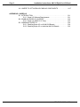
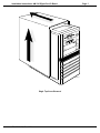
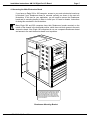
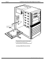
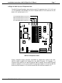
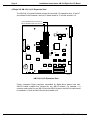
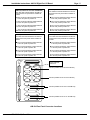
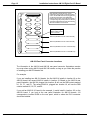
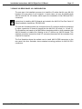
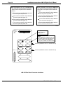
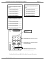
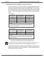
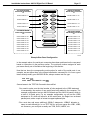
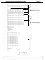
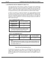
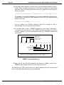
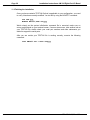
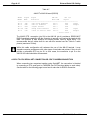
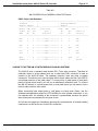
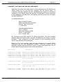
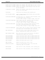
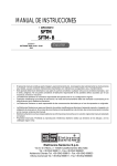
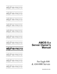
RIGHT. FROM THE START RIGHT. FROM THE START RIGHT. FROM THE START RIGHT. FROM THE START RIGHT. FROM THE START RIGHT. FROM THE START RIGHT. FROM THE START AM-318 Eight-Port Serial I/O Board Installation Instructions RIGHT. FROM THE START RIGHT. FROM THE START RIGHT. FROM THE START RIGHT. FROM THE START RIGHT. FROM THE START RIGHT. FROM THE START RIGHT. FROM THE START PDI-00318-00,Rev.A03 1995 Alpha Microsystems REVISIONS INCORPORATED REVISION 00 01 02 03 DATE May 1994 Sept. 1994 Nov. 1994 Nov. 1994 AM-318 Eight-Port Serial I/O Board Installation Instructions To re-order this document, request part number PDI-00318-00. The information contained in this manual is believed to be accurate and reliable. However, no responsibility for the accuracy, completeness or use of this information is assumed by Alpha Microsystems. This document may contain references to products covered under U.S. Patent Number 4,530,048. The following are registered trademarks of Alpha Microsystems, Santa Ana, CA 92799: AMIGOS AlphaBASIC AlphaLAN AlphaNET CASELODE AMOS AlphaCALC AlphaLEDGER AlphaPASCAL OmniBASIC Alpha Micro AlphaCOBOL AlphaMAIL AlphaRJE VER-A-TEL AlphaACCOUNTING AlphaFORTRAN 77 AlphaMATE AlphaWRITE VIDEOTRAX The following are trademarks of Alpha Microsystems, Santa Ana, CA 92799: AlphaBASIC PLUS DART inFront/am AlphaVUE ESP AM-PC MULTI AMTEC inSight/am All other copyrights and trademarks are the property of their respective holders. ALPHA MICROSYSTEMS 2722 S. Fairview Street P.O. Box 25059 Santa Ana, CA 92799 Installation Instructions: AM-318 Eight-Port I/O Board Page i TABLE OF CONTENTS 1.0 INTRODUCTION . . . . . . . . . . . . . . . . . . . . . . . . . . . . . . . . . . . . . . . . . . . . . . . . 1 2.0 PRODUCT DESCRIPTION . . . . . . . . . . . . . . . . . . . . . . . . . . . . . . . . . . . . . . . . 1 3.0 CONFIGURING YOUR AM-318 BOARD . . . . . . . . . . . . . . . . . . . . . . . . . . . . . . 1 3.1 Accessing Your Computer . . . . . . . . . . . . . . . . . . . . . . . . . . . . . . . . . . . 2 4.0 ELECTRONIC EQUIPMENT HANDLING PRECAUTIONS . . . . . . . . . . . . . . . . 4.1 Accessing the Main Electronics Board . . . . . . . . . . . . . . . . . . . . . . . . . . 4.2 Eagle 300 AM-319(-00) I/O Expansion Slots . . . . . . . . . . . . . . . . . . . . . 4.3 Eagle 200 AM-319(-10) I/O Expansion Slots . . . . . . . . . . . . . . . . . . . . . 4.4 Eagle 100 AM-137 I/O Expansion Slot . . . . . . . . . . . . . . . . . . . . . . . . . . 4 5 7 8 9 5.0 INSTALLING THE AM-318 BOARD . . . . . . . . . . . . . . . . . . . . . . . . . . . . . . . . . . 9 6.0 EAGLE 300 REAR PANEL I/O CONFIGURATION . . . . . . . . . . . . . . . . . . . . . . 10 7.0 EAGLE 200 REAR PANEL I/O CONFIGURATION . . . . . . . . . . . . . . . . . . . . . . 13 8.0 EAGLE 100 REAR PANEL I/O CONFIGURATION . . . . . . . . . . . . . . . . . . . . . . 16 9.0 INSTALLING THE AM-318’S RJ21 CONNECTOR . . . . . . . . . . . . . . . . . . . . . . 19 10.0 SYSTEM INITIALIZATION COMMAND FILE (EAGLE 200 AND 300) . . . . . . . 20 11.0 SYSTEM INITIALIZATION COMMAND FILE (EAGLE 100) . . . . . . . . . . . . . . 24 11.1 Finishing the Installation . . . . . . . . . . . . . . . . . . . . . . . . . . . . . . . . . . . . 28 APPENDIX A - EXTERNAL SERIAL I/O CABLING A.1 SIGNAL LIST AND MODULAR ADAPTERS . . . . . . . . . . . . . . . . . . . . . A.2 THE RJ21 METAL CONNECTOR . . . . . . . . . . . . . . . . . . . . . . . . . . . . . A.3 DB9 BREAKOUT BOXES AND CLUSTER CABLES. . . . . . . . . . . . . . A.4 CABLE CONFIGURATIONS TO CONNECT A TERMINAL WITH THE DB9 BREAK OUT BOX. . . . . . . . . . . . . . . . . . . . . . . . . . . . . A.5 CPU TO CPU SERIAL NET CONNECTION OR CPU TO MODEM CONNECTION . . . . . . . . . . . . . . . . . . . . . . . . . . . . . . . . . . A.6 HOW TO USE THE AM-318 WITH MODULAR CABLING SYSTEMS. . A.7 GUIDELINES FOR TERMINATING CABLE SHIELDS . . . . . . . . . . . . . PDI-00318-00, Rev. A03 A-1 A-6 A-6 A-11 A-12 A-13 A-14 Page ii Installation Instructions: AM-318 Eight-Port I/O Board A.8 WHERE TO GET MODULAR CABLING COMPONENTS. . . . . . . . . . . A-17 APPENDIX B - SUPER I/O B.1 INTRODUCTION . . . . . . . . . . . . . . . . . . . . . . . . . . . . . . . . . . . . . . . . . . B.1.1 Super I/O Software Requirements . . . . . . . . . . . . . . . . . . . . . B.2 ENABLING SUPER I/O SUPPORT . . . . . . . . . . . . . . . . . . . . . . . . . . . . B.2.1 Super I/O (AMOS 2.2C Only) . . . . . . . . . . . . . . . . . . . . . . . . . B.3 DISABLING SUPER I/O . . . . . . . . . . . . . . . . . . . . . . . . . . . . . . . . . . . . . B.3.1 Disabling Super I/O on All AM-318 Boards . . . . . . . . . . . . . . . B.3.2 Disabling Super I/O on Individual AM-318 Boards . . . . . . . . . B-1 B-1 B-2 B-3 B-4 B-4 B-5 PDI-00318-00, Rev. A03 Installation Instructions: AM-318 Eight-Port I/O Board Page 1 1.0INTRODUCTION This document describes the installation of AM-318 eight-port serial I/O boards into Eagle series computers. It is written for the experienced Alpha Micro Service Technician, so if you do not feel comfortable performing the hardware and software procedures discussed below, please contact your Alpha Micro Dealer or the Alpha Micro Technical Support Group for help. 2.0PRODUCT DESCRIPTION The AM-318 board supports eight asynchronous serial I/O ports using RS232 protocol. AM-318 boards do not support RS422. The Eagle 100 computer has a single I/O expansion slot that will support one AM-318 board; the Eagle 200 computer has two expansions slots and will support two AM-318 boards; the Eagle 300 computer has four expansion slots and will support four AM-318 boards. AM-318 boards use a modular style 50-pin RJ21 connector that mounts on the computer’s rear panel; this connector looks exactly like your computer’s external SCSI connector. AM-314 boards use standard female DB9 connectors. The rear panel of your Eagle computer has cutouts for both DB9 and RJ21 connectors. AM-318 board serial ports, as well as the Eagle 100’s eight on-board serial ports, can take advantage of a feature called Super I/O. Super I/O handles character output in a much more efficient manner than any other previously released AMOS serial port driver, which greatly reduces the load on the CPU and makes more CPU cycles available for other tasks. See Appendix B for more details. 3.0CONFIGURING YOUR AM-318 BOARD There are no jumpers on the AM-318 board. Nothing needs to be configured; the board is ready to install. An illustration of the AM-318 board is shown below: RN2 RN1 PIN-1 J1 U3 AM-318 U2 ALPHA MICROSYSTEMS MC1067 AM-318 Eight-Port Serial I/O Board PDI-00318-00, Rev. A03 Page 2 Installation Instructions: AM-318 Eight-Port I/O Board The AM-318 supports only RTS/CTS flow control signals; however, these signals are adequate for terminals, printers, some modems, PC connections, and AlphaNET serial connections. If required, the AM-314 four-port serial I/O board supports a full complement of RS232 signals, such as CD (carrier detect) and DTR (data terminal ready). 3.1Accessing Your Computer When adding an AM-318 serial I/O board to your computer, it will be necessary to remove your computer’s top cover. The top cover is held in place with four phillips-head screws located on the computer’s rear panel. To remove the top cover, remove all four screws from the locations indicated in the illustration below. Once the screws have been removed, the top cover can be slid back and removed. TOP COVER SCREWS 115 ENET MAIN ALT BOOT H1 SCSI H2 ETHERNET PARALLEL 0 PARALLEL 1 G1 G2 F1 F2 E1 E2 D1 D2 C1 C2 B1 B2 A1 A2 MC1018 Eagle Top Cover Screws PDI-00318-00, Rev. A03 Installation Instructions: AM-318 Eight-Port I/O Board Page 3 MC1010 Eagle Top Cover Removal PDI-00318-00, Rev. A03 Page 4 Installation Instructions: AM-318 Eight-Port I/O Board 4.0ELECTRONIC EQUIPMENT HANDLING PRECAUTIONS With the AC power cord unplugged and the top cover removed, the components inside your computer are vulnerable to damage caused by static discharge. Your body and clothing are capable of storing an electrical charge that can damage or destroy unprotected electronic components. Prior to handling any computer hardware, make sure your work area is properly protected against static discharge. There are a number of commercially available static protection devices, like the wrist strap shown below, designed specifically to protect your equipment from harmful static discharge. MC1012 Static Protection Wrist Strap PDI-00318-00, Rev. A03 Installation Instructions: AM-318 Eight-Port I/O Board Page 5 4.1Accessing the Main Electronics Board If you have an Eagle 200 or 300 computer, access to your main electronics board may be blocked if your Roadrunner board is mounted vertically, as shown in the next two illustrations. If this true for your application, you will need to remove the Roadrunner board and its mounting bracket in order to install your I/O board or boards. Instructions for doing this are shown in the illustrations. Many Eagle 200 and 300 computers have their Roadrunner boards mounted on the bottom of the chassis in the horizontal position, which does not block access to the main electronics board. Also, Eagle 100 computers do not use a separate Roadrunner board and access to the main electronics board is not a problem. DW F-2 075 4-0 0 MC1055 Your Roadrunner 030 or 040 board is mounted on the DWF-20754-00 bracket shown above. To access the board, you need to remove these four phillips-head screws. Once the screws are removed, the mounting bracket and board assembly can be folded down onto your work surface. Roadrunner Mounting Bracket PDI-00318-00, Rev. A03 Page 6 Installation Instructions: AM-318 Eight-Port I/O Board D OAR NB MAI ROADRUNNER 030 OR 040 BOARD MC1162 With the Roadrunner and its mounting bracket folded down out of the way, you will be able to access the main electronics board. Locating the Main Electronics Board PDI-00318-00, Rev. A03 Installation Instructions: AM-318 Eight-Port I/O Board Page 7 4.2Eagle 300 AM-319(-00) I/O Expansion Slots The AM-319 board illustration shows the four serial I/O expansion slots: J8, J9, J10, and J11. As indicated in the illustration, the first I/O board installs in J8, the second in J9, the third in J10, and the fourth in J11. 1ST I/O BOARD INSTALLS IN SLOT J8 2ND I/O BOARD INSTALLS IN SLOT J9 3RD I/O BOARD INSTALLS IN SLOT J10 4TH I/O BOARD INSTALLS IN SLOT J11 W1 W3 J13 W9 J12 W6 J14 W10 U6 J8 J9 J11 J10 J15 J3 J6 W5 J2 J1 J7 J5 BATTERY MC1062 AM-319 I/O Expansion Slots Factory integrated Eagle computers assembled by Alpha Micro always have their AM-314 boards installed first, followed by any AM-318 boards. For example, if a customer order called for two AM-318 and two AM-314 boards, the first AM-314 board would be installed in J8, the second AM-314 would be installed in J9, the first AM-318 board would be installed in J10, and the second AM-318 would be installed in J11. PDI-00318-00, Rev. A03 Page 8 Installation Instructions: AM-318 Eight-Port I/O Board 4.3Eagle 200 AM-319(-10) I/O Expansion Slots The AM-319(-10) board illustration shows the two serial I/O expansion slots: J6 and J7. As indicated in the illustration, the first I/O board installs in J7 and the second in J6. 1ST I/O BOARD INSTALLS IN SLOT J7 J10 W5 W8 2ND I/O BOARD INSTALLS IN SLOT J6 U3 W6 J1 W7 J4 U2 J6 J7 J2 W9 J9 BATTERY J5 J8 w4 w3 w2 w1 J3 MC1160 AM-319(-10) I/O Expansion Slots Factory integrated Eagle computers assembled by Alpha Micro always have their AM-314 boards installed first, followed by any AM-318 boards. For example, if a customer order called for one AM-318 and one AM-314 board, the AM-314 board would be installed in J7 and the AM-318 would be installed in J6. PDI-00318-00, Rev. A03 Installation Instructions: AM-318 Eight-Port I/O Board Page 9 4.4Eagle 100 AM-137 I/O Expansion Slot The AM-137 board illustration shows the one serial I/O expansion slot at location J6. BA TT W1 1ST (AND ONLY) I/O BOARD INSTALLS IN SLOT J6 J1 W2 SSD U14 ALPHA MICROSYSTEMS ER Y U15 J2 FOUR ON-BOARD (4-7) RS232 SERIAL PORTS FOUR ON-BOARD (0-3) RS232 SERIAL PORTS W3 J3 J4 OSCILLATOR JUMPERS DO NOT REMOVE W4 J5 W5 U28 U29 AM-137 J6 J8 J9 J7 W6 W7 W8 POWER W11 W9 RUN W10 DISK W12 J11 030 W13 W14 J10 MC1161 AM-137 I/O Expansion Slot The AM-137 board has one I/O expansion slot that will support one AM-314 or one AM318 I/O board. However, the AM-137 board has eight standard RS232 on-board serial ports, which are accessed on the rear panel of the computer via DB9 connectors. 5.0INSTALLING THE AM-318 BOARD The Eagles I/O expansion slots are very similiar to the type of slots memory SIMM modules plug into. The AM-318 board should be inserted into the appropriate slot with the component side of the AM-318 board facing your computer’s rear panel. The AM-318 must be inserted into the expansion slot at a slight angle and after you feel the board settle into the slot, you rotate it into an upright position. When the AM-318 is properly positioned, the metal retainer clips at each end of the expansion slot will click into position, locking the board in place. PDI-00318-00, Rev. A03 Page 10 Installation Instructions: AM-318 Eight-Port I/O Board Very little force is required to install an AM-318 board. If you’re having problems installing the board in the expansion slot, stop and take a moment to examine both the AM-318 and the slot. Make sure you are installing the AM-318 with the component side of the board facing your computer’s rear panel. 6.0EAGLE 300 REAR PANEL I/O CONFIGURATION The next step in the installation process is to install the I/O cables that link your AM-318 boards to the rear panel of your computer. In some cases, you may be installing both AM-318 and AM-314 I/O boards, which require the installation of both DB9 and RJ21 connectors. Instructions for installing AM-314 boards are located in the AM-314 Four-Port Serial I/O Board Installation Instructions, PDI-00314-00. The next two illustrations show how rear panel serial I/O connector positions correspond to where a particular I/O board is plugged into the AM-319 board (i.e., J8, J9, J10, and J11). The illustrations are based on the Alpha Micro standard procedure, which mandates that AM-314 boards be installed first (starting at slot J8) before any AM-318 boards. This standard procedure insures that serial I/O connector placement will be consistent from computer to computer. The first illustration shows the method used to install AM-314 DB9 connectors on the rear panel; the other illustration shows standard mounting positions for AM-318 RJ21 connectors. PDI-00318-00, Rev. A03 Installation Instructions: AM-318 Eight-Port I/O Board AM-314 (installed in slot J8 on the AM-319) The cable that extends between the AM-314 board and the rear panel will be installed as follows: Page 11 AM-314 (installed in slot J9 on the AM-319) The cable that extends between the AM-314 board and the rear panel will be installed as follows: The connector marked P0 will be attached to the rear panel as position H1. The connector marked P0 will be attached to the rear panel as position H2. The connector marked P1 will be attached to the rear panel at position G1. The connector marked P1 will be attached to the rear panel at position G2. The connector marked P2 will be attached to the rear panel at position F1. The connector marked P2 will be attached to the rear panel at position F2. The connector marked P3 will be attached to the rear panel at position E1. The connector marked P3 will be attached to the rear panel at position E2. AM-314 (installed in slot J10 on the AM-319) The cable that extends between the AM-314 board and the rear panel will be installed as follows: AM-314 (installed in slot J11 on the AM-319) The cable that extends between the AM-314 board and the rear panel will be installed as follows: The connector marked P0 will be attached to the rear panel as position D1. The connector marked P0 will be attached to the rear panel as position B1. The connector marked P1 will be attached to the rear panel at position D2. The connector marked P1 will be attached to the rear panel at position B2. The connector marked P2 will be attached to the rear panel at position C1. The connector marked P2 will be attached to the rear panel at position A1. The connector marked P3 will be attached to the rear panel at position C2. The connector marked P3 will be attached to the rear panel at position A2. MC1063 MAIN ALT BOOT H1 SCSI H2 ETHERNET PARALLEL 0 PARALLEL 1 G1 G2 F1 F2 E1 E2 D1 D2 C1 C2 B1 B2 A1 A2 Port #0 (the boot port) will be located at position H1. AM-314 (installed in slot J8 on the AM-319) AM-314 (installed in slot J9 on the AM-319) AM-314 (installed in slot J10 on the AM-319) AM-314 (installed in slot J11 on the AM-319) AM-314 Rear Panel Connector Locations PDI-00318-00, Rev. A03 Page 12 Installation Instructions: AM-318 Eight-Port I/O Board MAIN ALT BOOT H1 SCSI H2 ETHERNET PARALLEL 0 G1 G2 F1 F2 E1 E2 D1 D2 This diagram indicates the rear panel positions for 8-port RJ21 connectors based on the slot the AM-318 board is plugged into on the AM-319 board. This relationship between the I/O slot on the AM-319 and the corresponding rear panel position for the I/O connectors will remain true even when mixing AM-318 and AM-314 I/O boards. Port #0 (the boot port) will be located on this RJ21 connector. AM-318 (installed in slot J8 on the AM-319) C1 C2 AM-318 (installed in slot J9 on the AM-319) PARALLEL 1 B1 B2 AM-318 (installed in slot J10 on the AM-319) A1 A2 AM-318 (installed in slot J11 on the AM-319) MC1064 AM-318 Rear Panel Connector Locations The information in the AM-314 and AM-318 rear panel connector illustrations remains true even when mixing AM-314 and AM-318 boards, as long as you follow the practice of installing your AM-314 boards first. For example: If you are installing two AM-314 boards, the first AM-314 installs in location J8 on the AM-319 board; the second AM-314 installs in location J9. Based on the AM-314 rear panel illustration, the AM-314 plugged into location J8 will use the DB9 cutouts marked H1, G1, F1, and E1. The second AM-314, plugged into location J9, will use the DB9 cutouts marked H2, G2, F2, and E2. If you add an AM-318 I/O board to the example, it would install in location J10 on the AM-319 board. If you look at the rear panel illustration for AM-318 boards, J10 corresponds to location B1/B2 on the rear panel, which is where the RJ21 connector should be installed. PDI-00318-00, Rev. A03 Installation Instructions: AM-318 Eight-Port I/O Board Page 13 7.0EAGLE 200 REAR PANEL I/O CONFIGURATION The next step in the installation process is to install the I/O cables that link your AM-318 boards to the rear panel of your computer. In some cases, you may be installing both AM-318 and AM-314 I/O boards, which require the installation of both DB9 and RJ21 connectors. Instructions for installing AM-314 boards are located in the AM-314 Four-Port Serial I/O Board Installation Instructions, PDI-00314-00. The next two illustrations show how rear panel serial I/O connector positions correspond to where a particular I/O board is plugged into the AM-319(-10) board (i.e., J6 and J7). The illustrations are based on the Alpha Micro standard procedure, which mandates that AM-314 boards be installed first (starting at slot J7) before any AM-318 boards. This standard procedure insures that serial I/O connector placememt will be consistent from computer to computer. The first illustration shows the method used to install AM-314 DB9 connectors on the rear panel; the other illustration shows standard mounting positions for AM-318 RJ21 connectors. PDI-00318-00, Rev. A03 Page 14 Installation Instructions: AM-318 Eight-Port I/O Board AM-314 (installed in slot J7 on the AM-319-10) The cable that extends between the AM-314 board and the rear panel will be installed as follows: AM-314 (installed in slot J6 on the AM-319-10) The cable that extends between the AM-314 board and the rear panel will be installed as follows: The connector marked P0 will be attached to the rear panel as position F1. The connector marked P0 will be attached to the rear panel as position D1. The connector marked P1 will be attached to the rear panel at position F2. The connector marked P1 will be attached to the rear panel at position D2. The connector marked P2 will be attached to the rear panel at position E1. The connector marked P2 will be attached to the rear panel at position C1. The connector marked P3 will be attached to the rear panel at position E2. The connector marked P3 will be attached to the rear panel at positionC2. MC1163 MAIN ALT BOOT PARALLEL 0 Port #0 (the boot port) will be located at position F1. SCSI F1 F2 E1 E2 D1 D2 C1 C2 B1 B2 A1 A2 NOTE: Some Eagle 200 computers may not have these upper four DB9 cutouts; if this is the case for your application, simply use the lower four DB9 cutouts. AM-314 (installed in slot J7 on the AM-319-10) AM-314 (installed in slot J6 on the AM-319-10) AM-314 Rear Panel Connector Locations PDI-00318-00, Rev. A03 Installation Instructions: AM-318 Eight-Port I/O Board MAIN ALT BOOT PARALLEL 0 Page 15 This diagram indicates the rear panel positions for 8-port RJ-21 connectors based on the slot the AM-318 board is plugged into on the AM-319(-10) board. This relationship between the I/O slot on the AM-319(-10) and the corresponding rear panel position for the I/O connectors will remain true even when mixing AM-318 and AM-314 I/O boards. SCSI F1 F2 E1 E2 D1 D2 C1 C2 B1 B2 Port #0 (the boot port) will be located on this RJ-21 connector. AM-318 (installed in slot J7 on the AM-319-10) A1 A2 AM-318 (installed in slot J6 on the AM-319-10) MC1164 AM-318 Rear Panel Connector Locations The information in the AM-314 and AM-318 rear panel connector illustrations remains true even when mixing AM-314 and AM-318 boards, as long as you follow the practice of installing your AM-314 boards first. For example: If you are installing one AM-314 boards, the AM-314 installs in location J7 on the AM-319(-10) board and will use DB9 cutouts marked F1, F2, E1, and E2. If you add an AM-318 I/O board to the example, it would install in location J6 on the AM-319(-10) board. If you look at the rear panel illustration for AM-318 boards, J6 corresponds to location A1/A2 on the rear panel, which is where the RJ21 connector should be installed. PDI-00318-00, Rev. A03 Page 16 Installation Instructions: AM-318 Eight-Port I/O Board 8.0EAGLE 100 REAR PANEL I/O CONFIGURATION The Eagle 100’s AM-137 board only has one I/O expansion slot, but it also has eight on-board RS232 serial ports, which attach to the rear panel via standard DB9 connectors. Instructions for installing AM-314 boards are located in the AM-314 Four-Port Serial I/O Board Installation Instructions, PDI-00314-00. On the next two pages there are two illustration; the first illustration shows mounting locations for the eight on-board DB9 serial ports, plus the location of the four AM-314 DB9 serial ports; the other illustration also shows the eight on-board DB9 serial ports, plus the location of where the AM-318 RJ21 connector would be located. PDI-00318-00, Rev. A03 Installation Instructions: AM-318 Eight-Port I/O Board ON BOARD SERIAL PORTS 0 THROUGH 3 The cable that extends between the AM-314 board and the rear panel will be installed as follows: Page 17 ON BOARD SERIAL PORTS 4 THROUGH 7 The cable that extends between the AM-314 board and the rear panel will be installed as follows: The connector marked P0 will be attached to the rear panel as position F1. The connector marked P0 will be attached to the rear panel as position D1. The connector marked P1 will be attached to the rear panel at position F2. The connector marked P1 will be attached to the rear panel at position D2. The connector marked P2 will be attached to the rear panel at position E1. The connector marked P2 will be attached to the rear panel at position C1. The connector marked P3 will be attached to the rear panel at position E2. The connector marked P3 will be attached to the rear panel at positionC2. MC1163 AM-314 (installed in slot J6 on the AM-137 The cable that extends between the AM-314 board and the rear panel will be installed as follows: The connector marked P0 will be attached to the rear panel as position B1. The connector marked P1 will be attached to the rear panel at positionB2. The connector marked P2 will be attached to the rear panel at positionA1. The connector marked P3 will be attached to the rear panel at positionA2. MAIN ALT BOOT PARALLEL 0 Port #0 (the boot port) will be located at position F1. SCSI F1 F2 E1 E2 D1 D2 C1 C2 B1 B2 A1 A2 On-Board Serial Ports 0 - 3 (attached to connector J4 on the AM-137 Board On-Board Serial Ports 4 - 7 (attached to connector J5 on the AM-137 Board AM-314 (installed in slot J6 on the AM-137) Installing DB9 connectors in RJ21 cutouts requires a special adapter that is described in the AM-314 Installation Instructions. On-Board Serial Ports and AM-314 Rear Panel Connector I/O Locations PDI-00318-00, Rev. A03 Page 18 Installation Instructions: AM-318 Eight-Port I/O Board ON BOARD SERIAL PORTS 0 THROUGH 3 The cable that extends between the AM-314 board and the rear panel will be installed as follows: ON BOARD SERIAL PORTS 4 THROUGH 7 The cable that extends between the AM-314 board and the rear panel will be installed as follows: The connector marked P0 will be attached to the rear panel as position F1. The connector marked P0 will be attached to the rear panel as position D1. The connector marked P1 will be attached to the rear panel at position F2. The connector marked P1 will be attached to the rear panel at position D2. The connector marked P2 will be attached to the rear panel at position E1. The connector marked P2 will be attached to the rear panel at position C1. The connector marked P3 will be attached to the rear panel at position E2. The connector marked P3 will be attached to the rear panel at positionC2. MC1166 AM-318 (installed in slot J6 on the AM-137) The cable that extends between the AM-318 board and the rear panel will be installed at location B1/B2 MAIN ALT BOOT PARALLEL 0 Port #0 (the boot port) will be located at position F1. SCSI F1 F2 E1 E2 D1 D2 C1 C2 B1 B2 On-Board Serial Ports 0 - 3 (attached to connector J4 on the AM-137 Board On-Board Serial Ports 4 - 7 (attached to connector J5 on the AM-137 Board AM-318 (installed in slot J6 on the AM-137) A1 A2 On-Board Serial Ports and AM-318 Rear Panel Connector Locations PDI-00318-00, Rev. A03 Installation Instructions: AM-318 Eight-Port I/O Board Page 19 9.0INSTALLING THE AM-318’S RJ21 CONNECTOR Now that you know what connectors go where on your computer’s rear panel, you need to know how to perform the actual cable/connector installation. The AM-318 board uses a 50-pin cable with a standard 50-pin connector at one end and an RJ21 connector at the other. To install the cable: 1.Plug the end of the cable with the standard 50-pin connector into the J1 connector on the AM-318 board. Make sure the red stripe on the cable aligns with pin-1 on the AM-318 board’s 50-pin connector. Pin-1 is shown in the AM-318 board illustration, which appears at the beginning of this document. 2.Each RJ21 cutout on the rear of the Eagle chassis has a metal cover, which is held in place with two screws. You need to remove the cover plates from the RJ21 cutouts you plan to use. 3.From inside the chassis, insert the RJ21 connector through the RJ21 cutout. 4.The RJ21 connector is held in place with two bail-lock clips and two 4-40 phillips-head screws. The complete assembly is shown below: EAGLE REAR PANEL A2 A1 MC1066 AM-318 RJ21 I/O CONNECTOR BAIL-LOCK CLIP 4-40 PHILLIPS HEAD SCREW RJ21 Connector Installation PDI-00318-00, Rev. A03 Page 20 Installation Instructions: AM-318 Eight-Port I/O Board 10.0SYSTEM INITIALIZATION COMMAND FILE (EAGLE 200 AND 300) In order to use a serial port, it needs to be defined in your system initialization command file. This file, which is located in the SYS: account, is called AMOS32.INI. Within this file, serial ports are defined using an octal (base 8) numbering system. The octal number used corresponds directly to what slot on the AM-319 a particular I/O board is plugged into. The following table shows the corresponding AM-318 and AM-314 octal port numbers for each of the expansion slots on the AM-319(-00) and the AM-319(-10) boards: AM-319 BOARD AM-319 I/O EXPANSION SLOT OCTAL PORT NUMBERING FOR AM-318 BOARDS OCTAL PORT NUMBERING FOR AM-314 BOARDS J8 0-7 0 -3 J9 10 - 17 10 - 13 J10 20 - 27 20 - 23 J11 30 - 37 30 - 33 NOTE: The above port numbering scheme is true even if you are mixing AM-318 and AM-314 boards. For example, if you install an AM-318 board in slot J10 on the AM-319 board, you will use octal port numbers 20 - 27 regardless of what type of I/O boards are installed in connectors J89 and J9. AM-319(-10) BOARD AM-319(-10) I/O EXPANSION SLOT OCTAL PORT NUMBERING FOR AM-318 BOARDS OCTAL PORT NUMBERING FOR AM-314 BOARDS J7 0-7 0 -3 J6 10 - 17 10 - 13 NOTE: The above port numbering scheme is true even if you are mixing AM-318 and AM-314 boards. For example, if you install an AM-318 board in slot J6 on the AM-319(-10) board, you will use octal port numbers 10 - 17 regardless of what type of I/O board is installed in connector J7. Eagle 300 and 200 AM-318/314 Octal Port Numbering Scheme AM-318 board serial ports, as well as the Eagle 100’s eight on-board serial ports, can take advantage of a feature called Super I/O. See Appendix B for more details. To illustrate how serial ports are defined in the AMOS32.INI file, we’ll construct a sample system initialization command file based on a Eagle 300 configuration that includes two AM-314 boards and two AM-318 boards. A rear panel illustration based on this example is shown on the next page: PDI-00318-00, Rev. A03 Installation Instructions: AM-318 Eight-Port I/O Board 1ST AM-314 BOARD INSTALLED IN LOCATION J8 H1 SCSI H2 G1 G2 F1 F2 OCTAL PORT # = 11 OCTAL PORT # = 1 OCTAL PORT # = 12 OCTAL PORT # = 2 E1 E2 OCTAL PORT # = 3 OCTAL PORT # = 13 1ST AM-318 BOARD INSTALLED IN LOCATION J10 D1 D2 C1 C2 B1 B2 A1 A2 OCTAL PORT # = 20 2ND AM-318 BOARD INSTALLED IN LOCATION J11 OCTAL PORT # = 30 OCTAL PORT # = 22 OCTAL PORT # = 23 2ND AM-314 BOARD INSTALLED IN LOCATION J9 OCTAL PORT # = 10 OCTAL PORT # = 0 OCTAL PORT # = 21 Page 21 OCTAL PORT # = 31 OCTAL PORT # = 32 OCTAL PORT # = 33 OCTAL PORT # = 24 OCTAL PORT # = 34 OCTAL PORT # = 25 OCTAL PORT # = 35 OCTAL PORT # = 26 OCTAL PORT # = 36 OCTAL PORT # = 27 OCTAL PORT # = 37 MC1070 Example Rear Panel Configuration In the example above, the serial port connectors have been positioned on the rear panel based on instructions in the previous section. The octal port number assigned to each port came directly out of the table at the beginning of this section. Now that we know the corresponding octal number for each of the serial ports in our example, we can define them in the system initialization command file. It’s never a good idea to directly modify your AMOS32.INI file; always create a test file; type: LOG SYS: RETURN COPY TEST.INI=AMOS32.INI RETURN Several areas in the TEST.INI file need to be modified: 1.You need to make sure the total number of jobs assigned to the JOBS statement is increased by the number of new serial ports being added to the computer. The example configuration has two AM-318 boards and two AM-314 boards, which is a total of 24 serial ports. For our example configuration, we will set the JOBS statement to 30, which will allow for all the serial ports, the Eagle’s two on-board parallel ports, and a couple of extras to support spawned jobs. 2.You must also add some additional JOBALC statements. JOBALC allocates a name to each defined job. In our TEST.INI file, we’ll use names like JOB1, JOB2, etc. However, you could just as easily use TOM, DICK, HARRY, etc. PDI-00318-00, Rev. A03 Page 22 Installation Instructions: AM-318 Eight-Port I/O Board 3.Roadrunner based computers, like your Eagle, require a healthy quantity of queue blocks. When you add new serial ports, you have to increase your queue block allocation. Use the following queue block formula to determine how many queue blocks you require. NEW QUEUE BLOCK REQUIREMENT = OLD QUEUE BLOCKS + (13 x THE NUMBER OF JOBS) For example, if the QUEUE statement in your system initialization command file is currently set to 200 and the JOBS statement is set to 30, the resulting formula would look like this: NEW QUEUE BLOCK REQUIREMENT = 200 + (13 x 30) For our example, the QUEUE statement should be changed to 590 to accommodate our new queue block requirements. 4.You will also need to add a TRMDEF statement to your system initialization command file for each new port. The TRMDEF statement is where the octal port number is assigned. The basic elements that make up a TRMDEF statement are shown below: TRMDEF command Assigned name Serial port driver name Octal port number TRMDEF TERM7,AM318=20:19200,ALPHA,100,100,100 BAUD rate Terminal driver name In-width buffer size In-buffer size Out-buffer size NOTE: Make sure you use AM318 as the serial port driver name for AM-318 boards; use AM314 when creating a TRMDEF statement for an AM-314 board. MC1072 TRMDEF Command Statement 5.Finally, you will add SETJOB statements that attach the JOBALC name to the TRMDEF name, assign memory to the job, and log the job on. An Example of our TEST.INI file with all the support statements for the AM-314 and AM-318 boards is shown on the next page. PDI-00318-00, Rev. A03 Installation Instructions: AM-318 Eight-Port I/O Board :T JOBS 30 JOBALC JOB1,JOB2,JOB3,JOB4,JOB5,JOB6,JOB7,JOB8,JOB9,JOB10 JOBALC JOB11,JOB12,JOB13,JOB14,JOB15,JOB16,JOB17,JOB18 JOBALC JOB19,JOB20,JOB21,JOB22,JOB23,JOB24 ; QUEUE 590 ; TRMDEF TERM1,AM314=0:19200,ALPHA,100,100,100 TRMDEF TERM2,AM314=1:19200,ALPHA,100,100,100 TRMDEF TERM3,AM314=2:19200,ALPHA,100,100,100 TRMDEF TERM4,AM314=3:19200,ALPHA,100,100,100 TRMDEF TERM5,AM314=10:19200,ALPHA,100,100,100 TRMDEF TERM6,AM314=11:19200,ALPHA,100,100,100 TRMDEF TERM7,AM314=12:19200,ALPHA,100,100,100 TRMDEF TERM8,AM314=13:19200,ALPHA,100,100,100 TRMDEF TERM9,AM318=20:19200,ALPHA,100,100,100 TRMDEF TERM10,AM318=21:19200,ALPHA,100,100,100 TRMDEF TERM11,AM318=22:19200,ALPHA,100,100,100 TRMDEF TERM12,AM318=23:19200,ALPHA,100,100,100 TRMDEF TERM13,AM318=24:19200,ALPHA,100,100,100 TRMDEF TERM14,AM318=25:19200,ALPHA,100,100,100 TRMDEF TERM15,AM318=26:19200,ALPHA,100,100,100 TRMDEF TERM16,AM318=27:19200,ALPHA,100,100,100 TRMDEF TERM17,AM318=30:19200,ALPHA,100,100,100 TRMDEF TERM18,AM318=31:19200,ALPHA,100,100,100 TRMDEF TERM19,AM318=32:19200,ALPHA,100,100,100 TRMDEF TERM20,AM318=33:19200,ALPHA,100,100,100 TRMDEF TERM21,AM318=34:19200,ALPHA,100,100,100 TRMDEF TERM22,AM318=35:19200,ALPHA,100,100,100 TRMDEF TERM23,AM318=36:19200,ALPHA,100,100,100 TRMDEF TERM24,AM318=37:19200,ALPHA,100,100,100 ; DEVTBL DSK1,DSK2 DEVTBL TRM,RES,MEM DEVTBL /EPP0,/EPP1 ; BITMAP DSK SYSTEM TRM.DVR SYSTEM EPP.DVR[1,6] SYSTEM ; SETJOB JOB2,TERM2,500K,LOGIN SETJOB JOB3,TERM3,500K,LOGIN SETJOB JOB4,TERM4,500K,LOGIN SETJOB JOB5,TERM5,500K,LOGIN SETJOB JOB6,TERM6,500K,LOGIN SETJOB JOB7,TERM7,500K,LOGIN SETJOB JOB8,TERM8,500K,LOGIN SETJOB JOB9,TERM9,500K,LOGIN SETJOB JOB10,TERM10,500K,LOGIN SETJOB JOB11,TERM11,500K,LOGIN SETJOB JOB12,TERM12,500K,LOGIN SETJOB JOB13,TERM13,500K,LOGIN SETJOB JOB14,TERM14,500K,LOGIN SETJOB JOB15,TERM15,500K,LOGIN SETJOB JOB16,TERM16,500K,LOGIN SETJOB JOB17,TERM17,500K,LOGIN SETJOB JOB18,TERM18,500K,LOGIN SETJOB JOB19,TERM19,500K,LOGIN SETJOB JOB20,TERM20,500K,LOGIN SETJOB JOB21,TERM21,500K,LOGIN SETJOB JOB22,TERM22,500K,LOGIN SETJOB JOB23,TERM23,500K,LOGIN SETJOB JOB24,TERM24,500K,LOGIN ; MOUNT DSK1: MOUNT DSK2: ; MEMORY 0 Sample TEST.INI File PDI-00318-00, Rev. A03 Page 23 Update JOBS and JOBALC statements QUEUE block allocation increased TRMDEF statements for 1st AM-314 TRMDEF statements for 2nd AM-314 TRMDEF statements for 1st AM-318 TRMDEF statements for 2nd AM-318 SETJOB statements for all serial ports Page 24 Installation Instructions: AM-318 Eight-Port I/O Board 11.0SYSTEM INITIALIZATION COMMAND FILE (EAGLE 100) Unlike the Eagle 200 and 300 computers, all Eagle 100 computers come standard with eight RS232 serial ports, which are accessed on the computer’s rear panel via DB9 connectors. These eight serial ports are built into the Eagle 100’s main logic board, the AM-137. In addition to the eight on-board serial ports, the AM-137 board also has one I/O expansion slot where you can install one AM-314 or one AM-318 serial I/O board. In order to use a serial port, it needs to be defined in your system initialization command file. This file, which is located in the SYS: account, is called AMOS32.INI. Within this file, serial ports are defined using an octal (base 8) numbering system. The following table shows the corresponding AM-318 and AM-314 octal port numbers for the single I/O expansion slot (J6) on the AM-137, as well as the octal port numbers for the AM-137’s eight on board serial ports: AM-137 ON-BOARD SERIAL PORTS AM-137 BOARD'S EIGHT ON-BOARD I/O PORTS OCTAL PORT NUMBERING FOUR SERIAL PORTS CONNECTED TO J4 0-3 FOUR SERIAL PORTS CONNECTED TO J5 4-7 NOTE: The eight on-board serial ports use octal port numbers 0-7 and a driver called AM318.IDV, which is the same driver used by the eight port AM-318 I/O board. AM-137 J6 I/O EXPANSION SLOT AM-137 I/O EXPANSION SLOT OCTAL PORT NUMBERING FOR AM-318 BOARDS OCTAL PORT NUMBERING FOR AM-314 BOARDS J6 10-17 10-13 NOTE: You may wonder why octal port numbers 10-17 are used for the AM-318 board. The eight on-board serial ports use octal port numbers 0-7 and because the AM-318 and the on-board serial ports use the same driver (AM318.IDV), the AM-318 board must use octal port numbers 10-17. Eagle 100 Octal Port Numbering Scheme To illustrate how serial ports are defined in the AMOS32.INI file, we’ll construct a sample system initialization command file based on a Eagle 100 configuration that includes the eight on-board serial ports, plus one AM-318 board plugged into the AM-137’s J6 expansion slot. A rear panel illustration based on this example is shown on the next page: PDI-00318-00, Rev. A03 Installation Instructions: AM-318 Eight-Port I/O Board Page 25 MAIN ALT BOOT SCSI FOUR ON-BOARD SERIAL PORTS CONNECTED TO J4 ON THE AM-137 OCTAL PORT # = 0 FOUR ON-BOARD SERIAL PORTS CONNECTED TO J5 ON THE AM-137 F1 F2 E1 E2 OCTAL PORT # = 2 OCTAL PORT # = 3 D1 D2 C1 C2 OCTAL PORT # = 4 OCTAL PORT # = 5 OCTAL PORT # = 1 OCTAL PORT # = 6 AM-318 BOARD INSTALLED IN LOCATION J6 OCTAL PORT # = 10 OCTAL PORT # = 11 OCTAL PORT # = 7 B1 B2 OCTAL PORT # = 12 OCTAL PORT # = 13 OCTAL PORT # = 14 A1 A2 OCTAL PORT # = 15 OCTAL PORT # = 16 OCTAL PORT # = 17 MC1169 Example Rear Panel Configuration In the example above, the serial port connectors have been positioned on the rear panel based on instructions in the previous section. The octal port number assigned to each port came directly out of the table at the beginning of this section. Now that we know the corresponding octal number for each of the serial ports in our example, we can define them in the system initialization command file. It’s never a good idea to directly modify your AMOS32.INI file; always create a test file; type: LOG SYS: RETURN COPY TEST.INI=AMOS32.INI RETURN Several areas in the TEST.INI file need to be modified: 1.You need to make sure the total number of jobs assigned to the JOBS statement is increased by the number of new serial ports being added to the computer. The example configuration has one AM-318 board, plus the eight on-board serial ports, which is total of 16 serial ports. For our example configuration, we will set the JOBS statement to 30, which will allow for all the serial ports, the Eagle’s two on-board parallel ports, and a couple of extras to support spawned jobs. 2.You must also add some additional JOBALC statements. JOBALC allocates a name to each defined job. In our TEST.INI file, we’ll use names like JOB1, JOB2, etc. However, you could just as easily use TOM, DICK, HARRY, etc. PDI-00318-00, Rev. A03 Page 26 Installation Instructions: AM-318 Eight-Port I/O Board 3.Roadrunner based computers, like your Eagle, require a healthy quantity of queue blocks. When you add new serial ports, you have to increase your queue block allocation. Use the following queue block formula to determine how many queue blocks you require. NEW QUEUE BLOCK REQUIREMENT = OLD QUEUE BLOCKS + (13 x THE NUMBER OF JOBS) For example, if the QUEUE statement in your system initialization command file is currently set to 200 and the JOBS statement is set to 30, the resulting formula would look like this: NEW QUEUE BLOCK REQUIREMENT = 200 + (13 x 30) For our example, the QUEUE statement should be changed to 590 to accommodate our new queue block requirements. 4.You will also need to add a TRMDEF statement to your system initialization command file for each new port. The TRMDEF statement is where the octal port number is assigned. The basic elements that make up a TRMDEF statement are shown below: TRMDEF command Assigned name Serial port driver name Octal port number TRMDEF TERM7,AM318=20:19200,ALPHA,100,100,100 BAUD rate Terminal driver name In-width buffer size In-buffer size Out-buffer size NOTE: Make sure you use AM318 as the serial port driver name for AM-318 boards; use AM314 when creating a TRMDEF statement for an AM-314 board. MC1072 TRMDEF Command Statement 5.Finally, you will add SETJOB statements that attach the JOBALC name to the TRMDEF name, assign memory to the job, and log the job on. An Example of our TEST.INI file with all the support statements for the on-board serial ports and the AM-318 board is shown on the next page. PDI-00318-00, Rev. A03 Installation Instructions: AM-318 Eight-Port I/O Board :T JOBS 30 JOBALC JOB1,JOB2,JOB3,JOB4,JOB5,JOB6,JOB7,JOB8,JOB9,JOB10 JOBALC JOB11,JOB12,JOB13,JOB14,JOB15,JOB16,JOB17,JOB18 JOBALC JOB19,JOB20,JOB21,JOB22,JOB23,JOB24 ; QUEUE 590 ; TRMDEF TERM1,AM318=0:19200,ALPHA,100,100,100 TRMDEF TERM2,AM318=1:19200,ALPHA,100,100,100 TRMDEF TERM3,AM318=2:19200,ALPHA,100,100,100 TRMDEF TERM4,AM318=3:19200,ALPHA,100,100,100 TRMDEF TERM5,AM318=4:19200,ALPHA,100,100,100 TRMDEF TERM6,AM318=5:19200,ALPHA,100,100,100 TRMDEF TERM7,AM318=6:19200,ALPHA,100,100,100 TRMDEF TERM8,AM318=7:19200,ALPHA,100,100,100 TRMDEF TERM9,AM318=10:19200,ALPHA,100,100,100 TRMDEF TERM10,AM318=11:19200,ALPHA,100,100,100 TRMDEF TERM11,AM318=12:19200,ALPHA,100,100,100 TRMDEF TERM12,AM318=13:19200,ALPHA,100,100,100 TRMDEF TERM13,AM318=14:19200,ALPHA,100,100,100 TRMDEF TERM14,AM318=15:19200,ALPHA,100,100,100 TRMDEF TERM15,AM318=16:19200,ALPHA,100,100,100 TRMDEF TERM16,AM318=17:19200,ALPHA,100,100,100 ; DEVTBL DSK1,DSK2 DEVTBL TRM,RES,MEM DEVTBL /EGP0 ; BITMAP DSK SYSTEM TRM.DVR SYSTEM EGP.DVR[1,6] SYSTEM ; SETJOB JOB2,TERM2,500K,LOGIN SETJOB JOB3,TERM3,500K,LOGIN SETJOB JOB4,TERM4,500K,LOGIN SETJOB JOB5,TERM5,500K,LOGIN SETJOB JOB6,TERM6,500K,LOGIN SETJOB JOB7,TERM7,500K,LOGIN SETJOB JOB8,TERM8,500K,LOGIN SETJOB JOB9,TERM9,500K,LOGIN SETJOB JOB10,TERM10,500K,LOGIN SETJOB JOB11,TERM11,500K,LOGIN SETJOB JOB12,TERM12,500K,LOGIN SETJOB JOB13,TERM13,500K,LOGIN SETJOB JOB14,TERM14,500K,LOGIN SETJOB JOB15,TERM15,500K,LOGIN SETJOB JOB16,TERM16,500K,LOGIN ; MOUNT DSK1: MOUNT DSK2: ; MEMORY 0 Sample TEST.INI File PDI-00318-00, Rev. A03 Page 27 Update JOBS and JOBALC statements QUEUE block allocation increased TRMDEF statements for the four AM-137 on-board serial ports connected to J4 TRMDEF statements for the four AM-137 on-board serial ports connected to J5 TRMDEF statements for the AM-318 SETJOB statements for all serial ports Page 28 Installation Instructions: AM-318 Eight-Port I/O Board 11.1Finishing the Installation Once you have created a TEST.INI file that is applicable to your configuration, you need to verify it has been correctly modified. You do this by using the MONTST command: LOG OPR: RETURN MONTST AMOS32,TEST.INI RETURN Watch closely as the system initialization command file is executed; make sure no errors are displayed on your terminal screen. If an error does occur, take another look at your TEST.INI file; double check your octal port numbers and other statements you added to support the serial ports. After you are certain your TEST.INI file is working correctly, execute the following command: COPY AMOS32.INI = TEST.INI RETURN PDI-00318-00, Rev. A03 APPENDIX A EXTERNAL SERIAL I/O CABLING The following appendix contains cabling information for the external serial I/O (SIO) connector known as the RJ21. This Telco style connector was chosen for its compatibility with modular cabling systems that have become popular in recent years. This document describes the different components that make up a modular cabling system and contains information on the proper use and termination of cable shields. It also provides user information on how to plan an installation using modular cabling components. A.1SIGNAL LIST AND MODULAR ADAPTERS The following tables illustrate the signal-to-pin orientation for the AM-318 board’s RJ21 50-pin Telco connector. The first column identifies the port number. The second column shows the RS232 signal names assigned to the pins on the RJ21 50-pin connector, which are shown in the third column. The Telco color pair, shown in the fourth column, is the standard color code assignment for a 50-wire trunk cable. When this cable is attached to an RJ45 cluster cable or RJ45 break out box, the appropriate pin number is listed in the next column along with the associated color assignment. This standard is based on the Western Electric Color code (WECO standard) /USOC and pin assignment. The next column documents the pin assignments for the peripheral (CRT or printer) modular adapters for each port. All ports have the CTS handshake signal available. The last column documents the terminal’s modular adapter for each port configured for RS232. In this column, we show the terminal’s signal name and its pin assignment. All ports have the same pin out assignments. We have standardized on one type of modular adapter for all RS232 ports. In the CMS parts list at the end of this appendix, the modular adapters for RS232 are identified as 232-07 for all ports. PDI-00318-00, Rev. A03 Page A-2 External Serial I/O Cabling Table A-1 This table includes AM-318 I/O signal pinouts and shows the connection to modular adapters using RJ45 connectors. This table is based on the use of shielded trunk cable and un-shielded modular patch cord. USOC Standard Color Code AM-318 SERIAL I/O BOARD PORTS 0 - 3 AM-318 PORT NUMBER RS232 SIGNAL NAME 0. RxD RTS TxD nc CTS Gnd PERIPHERAL MODULAR ADAPTER CABLE AM-318 BOARD RJ21 50-PIN TELCO COLOR CONNECTOR PAIR 26 1 27 2 28 3 White Blue White Orange White Green Shield Gnd 1. RxD RTS TxD nc CTS Gnd 29 4 30 5 31 6 White Brown White Slate Red Blue Shield Gnd 2. RxD RTS TxD nc CTS Gnd 32 7 33 8 34 9 Red Orange Red Green Red Brown Shield Gnd 3. RxD RTS TxD nc CTS Gnd Shield Gnd 35 10 36 11 37 12 Red Slate Black Blue Black Orange RJ45 PIN COLOR RS232 SIGNAL NAME MDB-25 PIN NUMBER 5 4 3 6 2 7 8 1 Green Red Black Yellow Orange Brown Gray Blue TxD CTS RxD nc DTR Gnd nc Shield Gnd 2 5 3 nc 20 7 5 4 3 6 2 7 8 1 Green Red Black Yellow Orange Brown Gray Blue TxD CTS RxD nc DTR Gnd nc Shield Gnd 2 5 3 nc 20 7 5 4 3 6 2 7 8 1 Green Red Black Yellow Orange Brown Gray Blue TxD CTS RxD nc DTR Gnd nc Shield Gnd 2 5 3 nc 20 7 5 4 3 6 2 7 8 1 Green Red Black Yellow Orange Brown Gray Blue TxD CTS RxD nc DTR Gnd nc Shield Gnd 2 5 3 nc 20 7 1 1 1 1 MC1073 PDI-00318-00, Rev. A03 Installation Instructions: AM-318 Serial I/O Controller Page A-3 Table A-1 (cont.) USOC Standard Color Code AM-318 SERIAL I/O BOARD PORTS 4 - 7 AM-318 PORT NUMBER RS232 SIGNAL NAME 4. RxD RTS TxD nc CTS Gnd PERIPHERAL MODULAR ADAPTER CABLE AM-318 BOARD RJ21 50-PIN TELCO COLOR CONNECTOR PAIR 38 13 39 14 40 15 Black Green Black Brown Black Slate Shield Gnd 5. RxD RTS TxD nc CTS Gnd 41 16 42 17 43 18 Yellow Blue Yellow Orange Yellow Green Shield Gnd 6. RxD RTS TxD nc CTS Gnd 44 19 45 20 46 21 Yellow Brown Yellow Slate Violet Blue Shield Gnd 7. RxD RTS TxD nc CTS Gnd Shield Gnd 47 22 48 23 49 24 Violet Orange Violet Green Violet Brown PIN RJ45 COLOR RS232 SIGNAL NAME MDB-25 PIN NUMBER 5 4 3 6 2 7 8 1 Green Red Black Yellow Orange Brown Gray Blue TxD CTS RxD nc DTR Gnd nc Shield Gnd 2 5 3 nc 20 7 5 4 3 6 2 7 8 1 Green Red Black Yellow Orange Brown Gray Blue TxD CTS RxD nc DTR Gnd nc Shield Gnd 2 5 3 nc 20 7 5 4 3 6 2 7 8 1 Green Red Black Yellow Orange Brown Gray Blue TxD CTS RxD nc DTR Gnd nc Shield Gnd 2 5 3 nc 20 7 5 4 3 6 2 7 8 1 Green Red Black Yellow Orange Brown Gray Blue TxD CTS RxD nc DTR Gnd nc Shield Gnd 2 5 3 nc 20 7 1 1 1 1 MC1074 PDI-00318-00, Rev. A03 Page A-4 External Serial I/O Cabling Table A-2 This table includes AM-318 I/O signal pinouts and shows the connection to modular adapters using RJ12 connectors. This table is based on the use of shielded trunk cable and un-shielded modular patch cord. USOC Color Code Standard AM-318 SERIAL I/O BOARD PORTS 0 - 3 PERIPHERAL MODULAR ADAPTER CABLE AM-318 BOARD AM-318 PORT NUMBER RS232 SIGNAL NAME RJ21 50-PIN TELCO COLOR CONNECTOR PAIR 0. RxD RTS TxD nc CTS Gnd 26 1 27 2 28 3 White Blue White Orange White Green 4 3 2 5 1 6 1. RxD RTS TxD nc CTS Gnd 29 4 30 5 31 6 White Brown White Slate Red Blue 2. RxD RTS TxD nc CTS Gnd 32 7 33 8 34 9 3. RxD RTS TxD nc CTS Gnd 35 10 36 11 37 12 RJ12 COLOR RS232 SIGNAL NAME MDB-25 PIN NUMBER Green Red Black Yellow White Blue TxD CTS RxD nc DTR Gnd 2 5 3 nc 20 7 4 3 2 5 1 6 Green Red Black Yellow White Blue TxD CTS RxD nc DTR Gnd 2 5 3 nc 20 7 Red Orange Red Green Red Brown 4 3 2 5 1 6 Green Red Black Yellow White Blue TxD CTS RxD nc DTR Gnd 2 5 3 nc 20 7 Red Slate Black Blue Black Orange 4 3 2 5 1 6 Green Red Black Yellow White Blue TxD CTS RxD nc DTR Gnd 2 5 3 nc 20 7 PIN MC1075 PDI-00318-00, Rev. A03 Installation Instructions: AM-318 Serial I/O Controller Page A-5 Table A-2 (continued) USOC Color Code Standard AM-318 SERIAL I/O BOARD PORTS 4 - 7 PERIPHERAL MODULAR ADAPTER CABLE AM-318 BOARD RJ21 50-PIN TELCO COLOR CONNECTOR PAIR RS232 AM-318 PORT NUMBER RS232 SIGNAL NAME 4. RxD RTS TxD nc CTS Gnd 38 13 39 14 40 15 Black Green Black Brown Black Slate 4 3 2 5 1 6 Green Red Black Yellow White Blue TxD CTS RxD nc DTR Gnd 2 5 3 nc 20 7 5. RxD RTS TxD nc CTS Gnd 41 16 42 17 43 18 Yellow Blue Yellow Orange Yellow Green 4 3 2 5 1 6 Green Red Black Yellow White Blue TxD CTS RxD nc DTR Gnd 2 5 3 nc 20 7 6. RxD RTS TxD nc CTS Gnd 44 19 45 20 46 21 Yellow Brown Yellow Slate Violet Blue 4 3 2 5 1 6 Green Red Black Yellow White Blue TxD CTS RxD nc DTR Gnd 2 5 3 nc 20 7 7. RxD RTS TxD nc CTS Gnd 47 22 48 23 49 24 Violet Orange Violet Green Violet Brown 4 3 2 5 1 6 Green Red Black Yellow White Blue TxD CTS RxD nc DTR Gnd 2 5 3 nc 20 7 PIN RJ12 COLOR SIGNAL NAME MDB-25 PIN NUMBER MC1076 PDI-00318-00, Rev. A03 Page A-6 External Serial I/O Cabling A.2THE RJ21 METAL CONNECTOR To make an external connection to an AM-318 board, you must use a Telco style connector with a metal hood. The RJ21 cutout on the rear panel of your computer does not have enough clearance to allow the use of other types of RJ21 connectors. You should be using twisted pair, 24-26 gauge stranded low capacitance type wire that includes an overall shield and drain wire. Refer to the Installation and Planning Guide for more information on wire. We recommend that you use a metal shell connector with shielded, twisted pair wire, terminating the cable shield to the metal shell to comply with the FCC guidelines. Below are the part numbers for connectors that can be used with the AM-318 board. The first connector on the list is the bail-lock style shipped with the board. This type of connector is used with the cable components made by Cable Management Systems (CMS), described in the last section of this appendix. Alpha Micro Vendor Part No. Part No. Vendor Type --------------------------------------------------------------------------CNR-0003105 57-30500 Amphenol Solder Tail, Bail lock shell zinc plated --------------------------------------------------------------------------n/a 57-33500-1 Amphenol Solder Tail, Bail lock shell, Zinc plated. --------------------------------------------------------------------------n/a 157-32500 Amphenol Solderless, Insulation Displacement Bail lock shell, zinc plated --------------------------------------------------------------------------- A.3DB9 BREAKOUT BOXES AND CLUSTER CABLES. The next two tables show pin assignments and signal names for both an RJ45 cluster cable and a female DB9 break out box. These tables are identical in format to the preceding tables, but show in the last two columns, the pin assignment per port for a female DB9 break out box and the corresponding signal name for AM-318 I/O signals. We are providing this information so these components can be manufactured properly for use with the AM-318 board. Tables A-1 and A-2 document the male DB9 and DB25 modular adapters that attach to the connectors on the breakout box. PDI-00318-00, Rev. A03 Installation Instructions: AM-318 Serial I/O Controller Page A-7 Table A-3 MPS1-FDB9-ALPHA Female Breakout Box or RJ45 Cluster Cable USOC Color Code Standard AM-318 SERIAL I/O BOARD PORTS 0 - 3 RJ45 CLUSTER CABLE BREAKOUT BOX RS232 FDB-9 PIN NUMBER SIGNAL NAME AM-318 PORT NUMBER RS232 SIGNAL NAME RJ21 50-PIN CONNECTOR RJ45 COLOR CLUSTER CABLE PIN NUMBER 0. RxD RTS TxD nc CTS Gnd 26 1 27 2 28 3 Green Red Black Yellow Orange Brown Gray Blue 5 4 3 6 2 7 8 1 2 5 3 nc 4 7 8 1 RxD RTS TxD nc CTS Gnd nc Shield Gnd 29 4 30 5 31 6 Green Red Black Yellow Orange Brown Gray Blue 5 4 3 6 2 7 8 1 2 5 3 nc 4 7 8 1 RxD RTS TxD nc CTS Gnd nc Shield Gnd 32 7 33 8 34 9 Green Red Black Yellow Orange Brown Gray Blue 5 4 3 6 2 7 8 1 2 5 3 nc 4 7 8 1 RxD RTS TxD nc CTS Gnd nc Shield Gnd 35 10 36 11 37 12 Green Red Black Yellow Orange Brown Gray Blue 5 4 3 6 2 7 8 1 2 5 3 nc 4 7 8 1 RxD RTS TxD nc CTS Gnd nc Shield Gnd Shield Gnd 1. RxD RTS TxD nc CTS Gnd Shield Gnd 2. RxD RTS TxD nc CTS Gnd Shield Gnd 3. RxD RTS TxD nc CTS Gnd Shield Gnd MC1077 PDI-00318-00, Rev. A03 Page A-8 External Serial I/O Cabling Table A-3 (cont.) USOC Color Code Standard AM-318 SERIAL I/O BOARD PORTS 4 - 7 RJ45 CLUSTER CABLE BREAKOUT BOX RS232 FDB-9 PIN NUMBER SIGNAL NAME AM-318 PORT NUMBER RS232 SIGNAL NAME RJ21 50-PIN CONNECTOR RJ45 COLOR CLUSTER CABLE PIN NUMBER 4. RxD RTS TxD nc CTS Gnd 38 13 39 14 40 15 Green Red Black Yellow Orange Brown Gray Blue 5 4 3 6 2 7 8 1 2 5 3 nc 4 7 8 1 RxD RTS TxD nc CTS Gnd nc Shield Gnd 41 16 42 17 43 18 Green Red Black Yellow Orange Brown Gray Blue 5 4 3 6 2 7 8 1 2 5 3 nc 4 7 8 1 RxD RTS TxD nc CTS Gnd nc Shield Gnd 44 19 45 20 46 21 Green Red Black Yellow Orange Brown Gray Blue 5 4 3 6 2 7 8 1 2 5 3 nc 4 7 8 1 RxD RTS TxD nc CTS Gnd nc Shield Gnd 47 22 48 23 49 24 Green Red Black Yellow Orange Brown Gray Blue 5 4 3 6 2 7 8 1 2 5 3 nc 4 7 8 1 RxD RTS TxD nc CTS Gnd nc Shield Gnd Shield Gnd 5. RxD RTS TxD nc CTS Gnd Shield Gnd 6. RxD RTS TxD nc CTS Gnd Shield Gnd 7. RxD RTS TxD nc CTS Gnd Shield Gnd MC1078 PDI-00318-00, Rev. A03 Installation Instructions: AM-318 Serial I/O Controller Page A-9 Table A-4 MPS1-FDB9-ALPHA Breakout Box or RJ12 CLuster Cable USOC Color Code Standard AM-318 SERIAL I/O BOARD PORTS 0 - 3 RJ12 CLUSTER CABLE BREAKOUT BOX RS232 FDB-9 PIN NUMBER SIGNAL NAME AM-318 PORT NUMBER RS232 SIGNAL NAME RJ21 50-PIN CONNECTOR RJ12 COLOR CLUSTER CABLE PIN NUMBER 0. RxD RTS TxD nc CTS Gnd 26 1 27 2 28 3 Green Red Black Yellow White Blue 4 3 2 5 1 6 2 5 3 nc 4 7 8 RxD RTS TxD nc CTS Gnd nc 1. RxD RTS TxD nc CTS Gnd 29 4 30 5 31 6 Green Red Black Yellow White Blue 4 3 2 5 1 6 2 5 3 nc 4 7 8 RxD RTS TxD nc CTS Gnd nc 2. RxD RTS TxD nc CTS Gnd 32 7 33 8 34 9 Green Red Black Yellow White Blue 4 3 2 5 1 6 2 5 3 nc 4 7 8 RxD RTS TxD nc CTS Gnd nc 3. RxD RTS TxD nc CTS Gnd 35 10 36 11 37 12 Green Red Black Yellow White Blue 4 3 2 5 1 6 2 5 3 nc 4 7 8 RxD RTS TxD nc CTS Gnd nc MC1079 PDI-00318-00, Rev. A03 Page A-10 External Serial I/O Cabling Table A-4 (cont.) USOC Color Code Standard AM-318 SERIAL I/O BOARD PORTS 4 - 7 RJ12 CLUSTER CABLE BREAKOUT BOX RS232 FDB-9 PIN NUMBER SIGNAL NAME AM-318 PORT NUMBER RS232 SIGNAL NAME RJ21 50-PIN CONNECTOR RJ12 COLOR CLUSTER CABLE PIN NUMBER 4. RxD RTS TxD nc CTS Gnd 38 13 39 14 40 15 Green Red Black Yellow White Blue 4 3 2 5 1 6 2 5 3 nc 4 7 8 RxD RTS TxD nc CTS Gnd nc 5. RxD RTS TxD nc CTS Gnd 41 16 42 17 43 18 Green Red Black Yellow White Blue 4 3 2 5 1 6 2 5 3 nc 4 7 8 RxD RTS TxD nc CTS Gnd nc 6. RxD RTS TxD nc CTS Gnd 44 19 45 20 46 21 Green Red Black Yellow White Blue 4 3 2 5 1 6 2 5 3 nc 4 7 8 RxD RTS TxD nc CTS Gnd nc 7. RxD RTS TxD nc CTS Gnd 47 22 48 23 49 24 Green Red Black Yellow White Blue 4 3 2 5 1 6 2 5 3 nc 4 7 8 RxD RTS TxD nc CTS Gnd nc MC1080 PDI-00318-00, Rev. A03 Installation Instructions: AM-318 Serial I/O Controller Page A-11 For quick reference, the following chart shows the 50-pin I/O connector signal assignments. Table A-5 THE AM318 (RJ21) 50-Pin Input/Output Connector Signal Assignments +-------+------+------+------+------+------+------+------+------+ |Signal | PORT | PORT | PORT | PORT | PORT | PORT | PORT | PORT | |Name | # 0 | # 1 | # 2 | # 3 | # 4 | # 5 | # 6 | # 7 | +-------+------+------+------+------+------+------+------+------+ | RXD | 26 | 29 | 32 | 35 | 38 | 41 | 44 | 47 | +-------+------+------+------+------+------+------+------+------+ | RTS | 1 | 4 | 7 | 10 | 13 | 16 | 19 | 22 | +-------+------+------+------+------+------+------+------+------+ | TXD | 27 | 30 | 33 | 36 | 39 | 42 | 45 | 48 | +-------+------+------|------|------+------+------|------|------| | CTS | 28 | 31 | 34 | 37 | 40 | 43 | 46 | 49 | +-------+------+------+------+------+------+------+------+------+ | GND | 3 | 6 | 9 | 12 | 15 | 18 | 21 | 24 | +-------+------+------+------+------+------+------+------+------+ The following table shows which AM-318 I/O RS232 signal is on each pin of the DB9 break out box. Table A-6 DB9 Connector Break out Box Signals (MPS1-FDB9-ALPHA) DB9 Pin No. SIGNAL NAME (RS232) -------------------------------------------------1 P.Gnd (Shield Ground) 2 Input RxD (Rcv Data) 3 Output TxD (Xmt Data) 4 Input CTSx (Clr to Send) 5 Output RTSx (RTS PORTS 0 & 7) 6 nc nc 7 GND (Signal Ground) 8 nc nc 9 nc nc A.4CABLE CONFIGURATIONS TO CONNECT A TERMINAL WITH THE DB9 BREAK OUT BOX. When making a patch cord to connect between a terminal and a break out box, use a parallel patch cord terminated with RJ45s. Then use one male DB25 modular adapter to connect to the terminal and one male DB9 modular adapter to connect to the breakout box. Use the color code and pin definitions from Table A-1 to make these connections. The table below shows the signal flow and direction. PDI-00318-00, Rev. A03 Page A-12 External Serial I/O Cabling Table A-7 AM-65 To AM-318 board (RS232) AM-65 Signal Signal AM-318 CPU I/O MDB25 Name Direction Male DB9 Signal -------------------------------------------------------------------Pin 2 TxD Data from Terminal Pin 2 RxD Input Pin 3 RxD Data to Terminal Pin 3 TxD Output Pin 7 Gnd Signal Ground Pin 7 Gnd Pin 20 DTR Ready from Terminal Pin 4 CTS Input Pin 5 CTS Clear to Send to Term. Pin 5* RTS Output * Port 0 thru 7 The AM-65 DTR connection (pin 20) to the AM-318 (pin 4) provides a READY/NOT BUSY handshake capability with the computer to prevent over-running the terminal with data. This protocol is also effective for several printers used by Alpha Micro. It is recommended that all cables built for use with this terminal use the Table A-7 cable pinouts (maximum 50 feet). While this cable configuration will enhance the use of the AM-65 terminal, it may degrade computer performance with other types of terminals and printers if they do not provide a compatible DTR on pin 20. In such cases, the connection to pin 4 on the AM-318 I/O board should be disconnected. A.5CPU TO CPU SERIAL NET CONNECTION OR CPU TO MODEM CONNECTION When connecting two computers together using SerialNET, the connection is identical to connecting a CPU serial port to a MODEM (two DCE devices talking to each other). See the table on the following page to see how to make the for RS232 connection: PDI-00318-00, Rev. A03 Installation Instructions: AM-318 Serial I/O Controller Page A-13 Table A-8 AM-318 RS232 Port to MODEM or Other DCE Device USOC Color Code Standard -------------------+--------------------+------------------------------Standard | | Modified Modular Modular Adapter | | Adapter -------------------+--------------------+------------------------------AM-318 DB9 RJ45 Patch Cord RJ45 DB9 DCE Signal Pin Pin Color & Pin Pin Device or Name No. No. Direction No. No. CPU port -----------------------------------------------------------------------RxD RTS 2 5 5 4 <--------Grn----------< >--------Red----------> 5 4 3 4 TxD CTS TxD n/c 3 9 3 6 >--------Blk----------> >--------Yel----------> 3 6 2 open RxD n/c CTS Gnd 4 7 2 7 <--------Org----------< ---------Brn----------- 2 7 5 7 RTS Gnd Open Shield 1 8 1 ---------Gry-------------------Blu----------- 8 1 open 1 n/c Shield A.6HOW TO USE THE AM-318 WITH MODULAR CABLING SYSTEMS. The AM-318 uses a standard metal female RJ21 Telco style connector. Therefore all extension trunks or cluster cables must use a metal male RJ21 connector in order to connect to the AM-318 board. The standard extension trunk has male to female connectors. This allows you to connect Alpha Micro cluster cables and the Cylix DPP-25 overvoltage protector to the patch panel. To connect from a patch panel to mini-patch panels or punch down blocks, you will use a male/female extension trunk. To connect the AM-318 directly to a punch down block or mini-patch panel you will need to use a male to male extension trunk cable. When connecting base board jacks or wall plates to punch down blocks, use the shielded low-capacitance solid wire (STP4-ALPHA) for more reliable connections. If you use stranded wire, the reliability of the connection is questionable, because the punch down blocks were not designed for this type of wire. On the next two pages are illustrations showing the interconnection of modular cabling components, as well as the sex of the RJ21 connectors. PDI-00318-00, Rev. A03 Page A-14 External Serial I/O Cabling A.7GUIDELINES FOR TERMINATING CABLE SHIELDS There are two methods of terminating cable shields: 1.Terminate all trunk cables at the CPU. 2.Or, terminate all communication cables at the patch panels. The first method is used only when one or two trunk cables are being used. In this case, the cable shield can be grounded to the rear panel of the CPU chassis, providing a continuous earth ground. The second method is the preferred method of terminating cable shields. In many cases, the installation will use cluster cable connections with DB9 connectors attaching the ports of an AM-314 board to a patch panel. The trunk cable shield can then be grounded to the metal rack on the patch panel. Any trunk cables from AM-318 boards or any other I/O devices should also be terminated at the patch panel. Once all device shield grounds are attached to the patch panel, attach a half-inch braided copper wire to the nearest building earth ground, or the power conditioner if one is being used. The braided copper wire is ideal for getting rid of high frequency noise from the cable shields. Non-braided (round) wire does not work well because of its limited surface area. PDI-00318-00, Rev. A03 Installation Instructions: AM-318 Serial I/O Controller Page A-15 DATA PATCH PANEL 1 2 3 4 16 18 19 20 1 2 3 4 16 18 19 20 5 6 7 8 21 22 23 24 5 6 7 8 21 22 23 24 9 10 11 12 25 26 27 28 9 10 11 12 25 26 27 28 13 14 15 16 29 30 31 32 13 14 15 16 29 30 31 32 data patch panel alpha micro CABLE MANAGEMENT SYSTEMS The reverse side of this patch panel has eight RJ21 male connectors. MINI PATCH PANEL CMS TELCO RJ45 CONNECTOR DB9 BREAKOUT BOX 1 2 1 2 3 4 FEMALE RJ21 CONNECTOR 3 4 5 6 7 8 TELCO RJ45 CONNECTOR 5 6 FEMALE DB9 CONNECTOR 7 8 CMS CMS MC1081 Figure A-1 PDI-00318-00, Rev. A03 Page A-16 External Serial I/O Cabling RJ45 6' cluster cable for either male or female DB9 / DB25 modular adapters. AM-318 6' REAR PANEL MINI BREAKOUT BOX TRUNK CABLE AM-318 8 DB9 CONNECTORS REAR PANEL CMS CLUSTER CABLE AM-318 TRUNK CABLE 8' REAR PANEL MINI BREAKOUT BOX 20' AM-318 8 RJ45 CONNECTORS MTP-50 CMS MASS TERMINATION PROTECTION DATA PATCH PANEL AM-318 CMS AM-318 MINI PATCH PANEL AM-318 = FEMALE RJ21 CONNECTOR CLUSTER CABLE = MALE RJ21 CONNECTOR MC1082 ALL CABLE SHIELDS TO EARTH GROUND Figure A-2 PDI-00318-00, Rev. A03 Installation Instructions: AM-318 Serial I/O Controller Page A-17 A.8WHERE TO GET MODULAR CABLING COMPONENTS. Alpha Micro has chosen two cable vendors to make components for this modular type cabling system that are plug and play compatible with the AM-318 board. In cooperation with these suppliers, we have standardized part numbers for the different components in the cabling system. We have also set standards for these components for low capacitance type cable with overall shields, and shield drain wires for properly grounded installations. The cabling vendors are: Alpha Computer Solutions 4888 Loop Central Drive Suite 850 Houston, Texas 77081-2214 1-713-665-0477 Cable Management Systems 3510 S. Susan St. Santa Ana, California 92704 Phone 1-714-662-0664 FAX 1-714-662-1083 We recommend using these suppliers for cabling components. We have negotiated standard Alpha Micro dealer prices, and there are additional price breaks for volume purchases. These components have been selected for their compatibility with the AM-318, both electrically and mechanically. Below is a list of part numbers, along with their descriptions, for modular cabling components sold by Cable Management Systems. These part numbers are not applicable to Alpha Computer Solutions; however, for part number information, you can contact Alpha Computer Solutions at the number shown above. CMS Part No. Description M-DB9-232-07-45-ALPHA M-DB9-422-07-45-ALPHA M-DB25-232-09-45-ALPHA M-DB25-422-07-45-ALPHA F-DB25-XXX-07-45-ALPHA Modular Modular Modular Modular Modular pin out F-DB9-XXX-07-45-ALPHA Modular RJ45 adapter, Female DB9 Kit form, user will pin out for RS232. RJ45-CLC-8X6+2-ALPHA 8 port, 6 foot RJ45 Shielded Cluster Cable with Metal Hood, RJ21 Male conn. M-DB9-232-07-12-ALPHA M-DB9-422-07-12-ALPHA Modular RJ12 adapter, Male DB9 RS232 for port 0 thru 7 Modular RJ12 adapter, Male DB9 RS422 for ports 0 thru 7 PDI-00318-00, Rev. A03 RJ45 adapter, RJ45 adapter, RJ45 adapter, RJ45 adapter, RJ45 adapter, for RS232. Male DB9 RS232 for port 0 thru 7 Male DB9 RS422 for ports 0 thru 7 Male DB25 RS232 for port 0 thru 7 Male DB25 RS422 for port 0 thru 7 Female DB25 Kit form, user will Page A-18 External Serial I/O Cabling M-DB25-232-09-12-ALPHA M-DB25-422-07-12-ALPHA F-DB25-XXX-07-12-ALPHA Modular Modular Modular pin out F-DB9-XXX-07-12-ALPHA Modular RJ12 adapter, Female DB9 Kit form, user will pin out for either RS232. TR/TP-RG58 Transceiver Thin Ethernet with twisted pair. RJ12-CLC-8X6+2-ALPHA 8 port, 6 foot RJ12 Shielded Cluster Cable with Metal Hood, RJ21 Male conn. P-ECS25-8FT-50MF-ALPHA PVC 25pair Std. 8 ft. Extension Trunk with Metal hoods Std. Male/Female RJ21 connectors. Low Cap. Cable (12.5pf to 17.5pf) 24 AWG, solid wire. T-ECS25-8FT-50MF-ALPHA Teflon 25pair Std. 8ft. Extension Trunk with Metal hoods Std. Male/Female RJ21 connectors. Low Cap. Cable (12.5pf) 24 AWG, stranded wire. P-ECS25-XX-50MF-ALPHA PVC 25pair (XX= you specify Length) Extension Trunk with metal hoods Male/Female RJ21 connectors. Low Cap. Cable (12.5pf to 17.5pf) 24 AWG, solid wire. T-ECS25-XX-50MM-ALPHA Teflon 25pair (XX= you specify length) Extension Trunk with Metal hoods. Std Male/Male RJ21 connectors. MPS1-FDB9-ALPHA Mini Patch Panel, 8-port Female DB9, wired for the AM-318, Terminated with Female RJ21 connector. MPS1-RJ45X8+2-ALPHA Mini Patch Panel, 8-port RJ45 wired for the AM-318 Terminated with Female RJ21 connector. DPP-24-45-ALPHA DPP-48-45-ALPHA DPP-64-45-ALPHA DPP-96-45-ALPHA 24 48 64 96 MJB1-45-ALPHA Modular RJ45 Base board jack, 8 wire. MWP1-45-ALPHA Modular RJ45 Wall Plate jack, 8 wire. MCC8S-XX-45-ALPHA Parallel Shielded Modular patch cord, with RJ45 connectors, (XX= 1 to 25 Feet). MC8-XX-ALPHA Patch and line cords, RJ45/RJ45, 8 wire twisted pair MC6-XX-ALPHA Patch and line cords, RJ12/RJ12, 6 wire twisted pair port port port port RJ12 adapter, Male DB25 RS232 for port 0 thru 7 RJ12 adapter, Male DB25 RS422 for port 0 thru 7 RJ12 adapter, Female DB25 Kit form, user will for RS232. RJ45 RJ45 RJ45 RJ45 Patch Patch Patch Patch Panel Panel Panel Panel wired wired wired wired for for for for AM-318, AM-318, AM-318, AM-318, Male Male Male Male RJ21 RJ21 RJ21 RJ21 PDI-00318-00, Rev. A03 Installation Instructions: AM-318 Serial I/O Controller Page A-19 STP25-ALPHA PVC, 25-pair low cap (12.5pf to 17.5pf) solid twisted pair cable, with overall shield and drain wire. STP4 -ALPHA PVC, 4 pair, low cap (12.5pf to 17.5pf) solid twisted pair cable, with overall shield and drain wire. PTP25-ALPHA Plenum, Teflon 25 pair Low Cap. (12.5pf) twisted pair overall foil shielded with drain wire. PTP4 -ALPHA Plenum, Teflon 4 pair Low Cap (12.5pf) twisted pair overall foil shielded with drain wire. PDI-00318-00, Rev. A03 APPENDIX B SUPER I/O B.1INTRODUCTION Super I/O, which requires a PIC (Product Installation Code), is designed to significantly increase character output for all serial ports using the AM318.IDV driver. This includes all AM-318 board serial I/O ports, as well as the Eagle 100’s eight on-board serial ports. The more terminals you have on your system performing character output, the more you will benefit from Super I/O. For example: A Super I/O enabled Eagle 040 based computer with 32 AM-318 serial ports performing constant terminal output will transmit five times as many characters during a given time period, compared to the same configuration not using Super I/O. In the real world, of course, you won’t have 32 terminals performing constant terminal output, but this example should give you some idea of the Super I/O performance potential. Super I/O handles character output in a much more efficient manner than any other previously released AMOS serial port driver, which greatly reduces the load on the CPU and makes more CPU cycles available for other tasks. B.1.1Super I/O Software Requirements In order to use Super I/O, your AMOS operating system can be no earlier than AMOS 2.2C PR/8 94. Super I/O is not supported on 1.X AMOS operating systems. By late November, 1994, the Super I/O support files will be included on all factory integrated Eagle computers shipped by Alpha Micro. However, you will still need to enter the PIC code to enable Super I/O. PDI-00318-00, Rev. A03 Page B-2 Appendix B B.2ENABLING SUPER I/O SUPPORT The Super I/O product support software for AMOS 2.2C includes a number of files. For a complete list of exactly what files are included, see the release notes shipped with your product support kit software or the README file on AMTEC+. The files must be downloaded on top of your AMOS 2.2C operating system. Ideally, you will want to download the support files before you physically install your new AM-318 I/O boards. At the very least, the product support kit software must be in place before you boot from a system initialization command file that includes AM-318 TRMDEF statements. Once the files have been downloaded, you need to generate a new AMOS32.MON file that is compatible with the AM-318 board. The product support kit software includes a new monitor source file (AMOS.MON) used for creating your new monitor. This is done using the MONGEN command. You will want to create a test monitor first and then verify the monitor using the MONTST command. For example: LOG SYS: RETURN MONGEN RETURN Input monitor name: AMOS.MON RETURN New disk driver: SCZRR.DVR RETURN New language definition table name: ENGLSH RETURN New monitor name: TEST.MON RETURN SAVE TEST.MON RETURN The TEST.MON file you created must be AMOS 2.2C (452)-12 or later. Once the test monitor has been created and saved, you need to verify that it works. This is done using the MONTST command, for example: LOG OPR: RETURN MONTST TEST.MON,AMOS32.INI RETURN Watch your display screen and make sure the new monitor boots without error. Once you are satisfied the new monitor is working correctly, copy it over to your AMOS32.MON file; for example: LOG SYS: RETURN COPY AMOS32.MON=TEST.MON RETURN After creating your AM-318 compatible AMOS32.MON file, proceed to the next section, which describes how to enable Super I/O. PDI-00318-00, Rev. A03 Super I/O Page B-3 B.2.1Super I/O (AMOS 2.2C Only) Super I/O, which requires a PIC (Product Installation Code), is designed to significantly increase character output for all serial ports using the AM318.IDV driver. Super I/O handles character output in a much more efficient manner than any other previously released AMOS serial port driver, which greatly reduces the load on the CPU and makes more CPU cycles available for other tasks. In order to use Super I/O, you must download the contents of the Super I/O product support kit software on top of your AMOS 2.2C operating system. Be sure to follow any instructions included in the Super I/O Product Support Kit Release Notes. The Super I/O product support kit software will also be available on AMTEC+. Once you enter the product installation code (PIC), the product overlay file is forever modified and will not accept a new PIC. This can be a problem if you happen to enter an incorrect PIC. As a safeguard, make a copy of the Super I/O overlay file before you do the SSD encodement. Type: COPY SER000.SAV=SER000.OVR RETURN By saving an unmodified version of the overlay file, you will be able re-enter the PIC if necessary. To perform the SSD encodement, enter the following commands: LOG SYS: RETURN SERPIC RETURN You will be prompted for a Product Installation Code (PIC). If after entering the SERPIC command, the program responds by displaying a PIC, this indicates the encoding has already been completed. Nothing else needs to be done, assuming, of course, the PIC displayed matches the code given to you by Alpha Micro. This PIC is a unique identifier for your system that must be purchased and obtained from Alpha Micro. Enter the PIC, carefully verifying you have entered it correctly and press RETURN . After a brief pause, you will be returned to AMOS command level and you can proceed with the remainder of the installation. If you see the error message ?Improper SSD after you have rebooted the computer, it probably means you have entered the PIC incorrectly. PDI-00318-00, Rev. A03 Page B-4 Appendix B As mentioned above, you cannot SSD encode the same overlay twice; to re-encode the Super I/O software, do this command first: COPY SER000.OVR=SER000.SAV RETURN You will now be able to re-encode the Super I/O. If after once again rebooting the computer you still receive the same error, check with your dealer to make sure the correct PIC was supplied for your computer. After the PIC procedure is completed and the computer has been rebooted, all serial ports using the AM318.IDV driver will be able to take advantage of Super I/O. B.3DISABLING SUPER I/O For most of your AM-318 serial ports, you will want to always have Super I/O enabled. However, if you have some application program that does not run properly on a Super I/O enabled serial port, it is possible to disable Super I/O. You can disable Super I/O on one or more AM-318 boards, but you can’t disable Super I/O on an individual serial port. B.3.1Disabling Super I/O on All AM-318 Boards If the application causing problems is one you run infrequently, you can temporarily disable Super I/O on all your AM-318 ports by using the following procedure: 1.Create a copy of your system initialization command file; type: LOG 1,4 RETURN COPY TEST.INI=AMOS32.INI RETURN 2.Use AlphaVUE to modify your TEST.INI file. Locate the first AM318 TRMDEF statement. Disable Super I/O by adding /O (that’s an "O," not a zero) to the first AM-318 TRMDEF statement. For example, change: TRMDEF TERM2,AM318=0:19200,AM65,100,100,100 to TRMDEF TERM2,AM318/O=0:19200,AM65,100,100,100 3.Finish out of the AlphaVUE file by pressing Then press G and press the RETURN key. ESC to reach Command Mode. 4.The MONTST command will force your computer to boot from the TEST.INI file. The /O switch will disable Super I/O on all AM-318 I/O boards. PDI-00318-00, Rev. A03 Super I/O Page B-5 5.Once you have completed running the program that exhibits problems under Super I/O, you can reboot your computer using the standard system initialization command file, which will reactivate Super I/O. B.3.2Disabling Super I/O on Individual AM-318 Boards When your computer is processing your system initialization command file, it loads a copy of the AM318.IDV file when it encounters the first TRMDEF statement for an AM-318 board. This same copy of the AM318.IDV file is used for all subsequent AM-318 boards. This being the case, if you use the /O switch in the first AM-318 TRMDEF statement, Super I/O is disabled on all AM-318 boards in your computer. In some cases, you may want disable Super I/O on a particular AM-318 board, while leaving Super I/O enabled on your other AM-318 boards. The procedure for doing this is as follows: 1.First, make a copy of your AM318.IDV file; make sure the copy uses a name other than AM318.IDV. For example, while in the DVR: account, type: COPY AM318S.IDV=AM318.IDV RETURN 2.Create a copy of your system initialization command file; type: LOG 1,4 RETURN COPY TEST.INI=AMOS32.INI RETURN 3.Use AlphaVUE to modify the TEST.INI file. Locate the AM-318 board (or boards) for which you want to disable Super I/O. For all eight of the TRMDEF statements substitute AM318S in place of AM318. Do this only for the AM-318 boards for which you want to disable Super I/O. 4.Now, you must add the /O switch to the very first TRMDEF statement that uses the AM318S driver. For example: TRMDEF TERM17,AM318S/O=20:19200,AM65,100,100,100 ESC to reach Command 5.Finish out of the AlphaVUE file by pressing Mode. Then type G and press the RETURN key. The MONTST command will force your computer to boot from the TEST.INI file. The /O switch will disable Super I/O only for the AM-318 boards using the AM318S driver. All AM-318 boards using the AM318 driver will remain Super I/O enabled. All Super I/O and AM-318 support software described in this appendix can be downloaded from AMTEC+ or it can be ordered separately from Alpha Micro. Part number PSB-04057-44 (Super I/O PSK 2.2C) contains the AM-318 support and Super I/O software for AMOS 2.2C; the AM-318 support software for AMOS 1.4C is available on AMTEC+. PDI-00318-00, Rev. A03