1
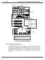
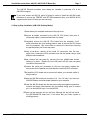
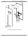
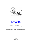
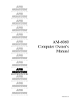
RIGHT. FROM THE START RIGHT. FROM THE START RIGHT. FROM THE START RIGHT. FROM THE START RIGHT. FROM THE START AM-338/339 RIGHT. FROM THE START RIGHT. FROM THE START RJE Board Set Installation Instructions RIGHT. FROM THE START RIGHT. FROM THE START RIGHT. FROM THE START RIGHT. FROM THE START RIGHT. FROM THE START RIGHT. FROM THE START RIGHT. FROM THE START PDI-00338-00,Rev.02 1995 Alpha Microsystems REVISIONS INCORPORATED REVISION 00 01 02 DATE July 1991 Feb. 1992 Nov. 1994 AM-338/339 RJE Board Set Installation Instructions To re-order this document, request part number PDI-00338-00. The information contained in this manual is believed to be accurate and reliable. However, no responsibility for the accuracy, completeness or use of this information is assumed by Alpha Microsystems. This document may contain references to products covered under U.S. Patent Number 4,530,048. The following are registered trademarks of Alpha Microsystems, Santa Ana, CA 92799: AMIGOS AlphaBASIC AlphaLAN AlphaNET CASELODE AMOS AlphaCALC AlphaLEDGER AlphaPASCAL OmniBASIC Alpha Micro AlphaCOBOL AlphaMAIL AlphaRJE VER-A-TEL AlphaACCOUNTING AlphaFORTRAN 77 AlphaMATE AlphaWRITE VIDEOTRAX The following are trademarks of Alpha Microsystems, Santa Ana, CA 92799: AlphaBASIC PLUS DART inFront/am AlphaVUE ESP AM-PC MULTI AMTEC inSight/am All other copyrights and trademarks are the property of their respective holders. ALPHA MICROSYSTEMS 2722 S. Fairview Street P.O. Box 25059 Santa Ana, CA 92799 Installation Instructions: AM-338 / AM-339 RJE Board Set Page i TABLE OF CONTENTS 1.0 INTRODUCTION . . . . . . . . . . . . . . . . . . . . . . . . . . . . . . . . . . . . . . . . . . . . . . . . 1 2.0 DESCRIPTION . . . . . . . . . . . . . . . . . . . . . . . . . . . . . . . . . . . . . . . . . . . . . . . . . . 1 3.0 CONFIGURING THE AM-338/339 BOARDS . . . . . . . . . . . . . . . . . . . . . . . . . . . 1 4.0 AM-1600 AM-338/339 INSTALLATION . . . . . . . . . . . . . . . . . . . . . . . . . . . . . . . 4.1 Step by Step Installation (AM-1600 Desktop Model) . . . . . . . . . . . . . . . 4.2 Step by Step Installation (AM-1600 Deskside Model) . . . . . . . . . . . . . . 4.3 Software Installation for the AM-1600 . . . . . . . . . . . . . . . . . . . . . . . . . . 4.4 Configuring RJE for the AM-1600 . . . . . . . . . . . . . . . . . . . . . . . . . . . . . . 2 3 4 4 5 5.0 EAGLE AM-338/339 INSTALLATION . . . . . . . . . . . . . . . . . . . . . . . . . . . . . . . . 5.1 Step by Step Installation for Eagle Computers . . . . . . . . . . . . . . . . . . . . 5.2 Software Installation . . . . . . . . . . . . . . . . . . . . . . . . . . . . . . . . . . . . . . . . 5.3 Configuring RJE . . . . . . . . . . . . . . . . . . . . . . . . . . . . . . . . . . . . . . . . . . . 5 6 9 9 6.0 RUNNING ALPHARJE 4.0 . . . . . . . . . . . . . . . . . . . . . . . . . . . . . . . . . . . . . . . . . 10 PDI-00338-00, Rev. A02 Installation Instructions: AM-338 / AM-339 RJE Board Set Page 1 1.0INTRODUCTION This document describes the RJE AM-338/AM-339 board set installation for Alpha Micro AM-1600 (Desktop and Deskside) and Eagle series computers. It’s written for the experienced Alpha Micro Service Technician, so if you do not feel comfortable performing the hardware procedures discussed below, please contact your Alpha Micro Dealer or the Alpha Micro Technical Support Group for help. 2.0DESCRIPTION The AM-338/AM-339 board set provides a bisync interface for your computer, allowing communication with IBM mainframes when used in conjunction with AlphaRJE software. The AM-338 board provides buffering, interrupt handling, and decoding functions required by your computer’s serial I/O interface. The AM-339 board is a single board computer, software compatible with the AM-330 board used in AMOS computers that support the 60-pin AM-355 I/O bus. Features: Z-80 8 bit processor running at 4MHz. Standard Z-80 peripherals for parallel data transfer, serial transfer, and clock/counter functions. 64K static RAM memory, 8K bootstrap PROM. Dual phantoms for initial processor reset and bootstrap PROM enable. Programmable interrupt vector, software reset function. Program download from host CPU. 3.0CONFIGURING THE AM-338/339 BOARDS Before installing the AM-338/AM-339 board set, make sure both boards are configured as shown in Figure 1; the AM-339 board must have its jumpers configured in the DTE (default) position. PDI-00338-00, Rev. A02 Page 2 Installation Instructions: AM-338 / AM-339 RJE Board Set AM-339 TO AM-338 BOARD PIN-1 J1 OSCILLATOR JUMPER DO NOT REMOVE W1 J2 J3 25-pin 9-pin SYNCHRONOUS COMMUNICATION PORT DTE JUMPER SETTING (DEFAULT) W1 DCE JUMPER SETTING W1 9-Pin Connector: 25-Pin Connector: DCE (TEST MODE) AM-338 AM-339 I/O PINOUTS DEBUG / TRACE PORT W1 PIN-1 TO AM-339 BOARD 2 - RXD 3 - TXD 4 - CTS 5 - RTS 6 - DTR 7 - GND 8 - DCD (not used) (not used) (not used) (not used) 2 - TXD (DTE mode) RXD (DCE mode) 3 - RXD (DTE mode) TXD (DCE mode) 4 - RTS (DTE mode) CTS (DCE mode) 5 - CTS (DTE mode) RTS (DCE mode) 6 - DTR (DCE mode) 7 - GND 8 - DCD 15 - TXC (transmit clock) - input 17 - RXC (receive clock) - input 20 - DTR (DTE mode) W1 J1 OSCILLATOR JUMPER DO NOT REMOVE FACTORY PRESET DO NOT RECONFIGURE MAC5 5 5 NOTE: Test Mode is used for loopback diagnostics. An internal clock is generated so no external modem is required. Test Mode cannot be used for linking two RJE boards - An external modem must be used for that purpose. Figure 1. AM-338/AM-339 RJE Board Set 4.0AM-1600 AM-338/339 INSTALLATION The AM-338 board occupies one I/O expansion connector on the AM-1600’s CPU board, the AM-135. Depending on the configuration of your computer, the AM-338 will be installed in the AM-135 board’s J14 or J15 I/O expansion connector. If you have an AM-366 Ethernet controller installed in your computer, the AM-338 board must be installed in J15. For installations without an AM-366 board, the AM-338 board will be installed in J14. PDI-00338-00, Rev. A02 Installation Instructions: AM-338 / AM-339 RJE Board Set Page 3 The AM-366 Ethernet controller must always be installed in connector J14 in the AM-1600 computer. If you must remove an AM-314 serial I/O board in order to install the AM-338 board, remember to remove the TRMDEF and SETJOB statements from your AMOSL.INI file supporting the serial I/O board you are removing. 4.1Step by Step Installation (AM-1600 Desktop Model) 1.Power down your computer and remove the top cover. 2.Remove all cables connected to the AM-135 CPU board, take note of where each cable is connected and how it is routed. 3.Completely remove the AM-135 CPU board from the computer. You’ll need to squeeze the nylon locking posts in order to remove the CPU board from the computer. Use a hex-driver to remove the hex-screws securing the parallel printer port to the rear panel. 4.Using a hex-driver, remove all the serial I/O connectors from the rear panel. Also, remove the SCSI connector from the rear panel using a small phillips-head screwdriver. 5.Now, remove the rear panel by removing the four phillips-head screws holding it in place. Replace the old rear panel with the new rear panel included in the product kit. 6.Connect the serial port connectors to the new rear panel, replace the hex-screws for the parallel port, and attach the external SCSI connector. 7.Re-install the CPU board and re-connect all cables you removed earlier in this procedure. 8.Insert the AM-338 board into connector J14. Use J15 only if you have an AM-366 Ethernet controller board installed in your computer. 9.Screw the AM-339 board into the rear panel using the supplied screws and connect the ribbon cable between the two boards; being sure to connect pin-1 on the AM-338 to pin-1 on the AM-339. 10.Power up the computer and run self test. Although self test will not check the AM-338/AM-339 board set, it will insure that your basic system is working properly. PDI-00338-00, Rev. A02 Page 4 Installation Instructions: AM-338 / AM-339 RJE Board Set A simple diagnostic to verify the operation of the AM-339 board is to use an an oscilloscope to watch the DTR line (pin 20 on the DB-25 connector). After a reset, DTR will go low for around two seconds while the AM-339 performs a memory self test. After memory self test has completed, DTR will go high. 11.Once self test has passed, power the computer down again and replace the top cover. 4.2Step by Step Installation (AM-1600 Deskside Model) 1.Power down your computer and remove the top cover. 2.Remove your computer’s top cover, following the instructions in the AM1600 Deskside Computer Service Manual. 3.Insert the AM-338 board into connector J14. Use J15 only if you have an AM-366 Ethernet controller board installed in your computer. 4.To install the AM-339 board, use the instructions in Section 5.1 "Step by Step Instructions for Eagle Computers." Perform all the instuctions in steps 1 through 7. After you have completed the AM-339 installation, continue the procedure at Section 4.3. 4.3Software Installation for the AM-1600 AlphaRJE version 4.0(122) or later is required in order to use the AM-338/AM-339 board set. Download the AlphaRJE software onto your computer’s hard disk drive; for example: LOG OPR: STRRES DSK0:[]=ALL:[] No changes are required to the AM-1600’s AMOSL.INI file in order to run AlphaRJE. Note the first time you run AlphaRJE, you will be asked to enter a Product Installation Code (or PIC). To do so, execute the RJE program from AMOS command level. This PIC is a unique indentifier for your computer that must be obtained from your dealer. Enter the PIC, carefully verifying you have entered it correctly and press RETURN . PDI-00338-00, Rev. A02 Installation Instructions: AM-338 / AM-339 RJE Board Set Page 5 After a brief pause, you should be returned to AMOS command level and you can proceed with the remainder of the installation. If you see the error message ?Improper SSD, verify you entered the correct PIC by re-installing the software and trying again. If you still receive the same error, check with your dealer to make sure the correct PIC was supplied for your computer. You must successfully complete this portion of the AlphaRJE installation for any other portion to work. 4.4Configuring RJE for the AM-1600 In order to run AlphaRJE, you need to run two other programs prior to using RJE to communicate with the IBM computer. The CONFIG program allows you to change various options and the CACOTA program generates a carriage control tape file for report formatting on IBM hosts that use carriage control. The CONFIG program is the same as in previous versions of AlphaRJE; only now the I/O address field will accept full 32 bit values. When you run CONFIG, use the following values for the I/O address field: If your AM-338 board is in J14, use FFFFFCC1. If your AM-338 board is in J15, use FFFFFC81. The interrupt level does not matter and may be any value from zero to seven. 5.0EAGLE AM-338/339 INSTALLATION In order to use the RJE AM-338/339 board set in an Eagle computer, the following items must be true: The AM-172 board used in Eagle computers must have a H00 (or later) boot PROM. The AM-174 board used in Eagle computers must have a E00 (or later) boot PROM. The AM-319(-10) board used in Eagle 200 computers must be at revision A01 or later. The AM-319(-00) board used in Eagle 300, 400, and 500 computers must be at revision C02 or later for C revision artwork and B08 or later for B revision artwork. All Eagle 100 computers are AM-338/399 compatible. The Eagle computer’s operating system can be no earlier than PR8/94 AMOS 1.4C or AMOS 2.2C. PDI-00338-00, Rev. A02 Page 6 Installation Instructions: AM-338 / AM-339 RJE Board Set 5.1Step by Step Installation for Eagle Computers Follow the instructions in your Eagle Computer Service Manual that explain how to remove your computer’s top cover. The service manual also includes configuration drawings for AM-137, AM-319-00, and AM-319-10 boards. These drawings show the location of the I/O expansion connectors. The AM-338 board must be plugged into a specific connector in Eagle computers: In the Eagle 100 computer, the AM-338 board plugs into the J6 I/O expansion connector. In the Eagle 200 computer, the AM-338 board plugs into the J6 I/O expansion connector. In the Eagle 300 computer, the AM-338 board plugs into the J11 I/O expansion connector. If you must remove an AM-314 or AM-318 serial I/O board in order to install the AM-338 board, remember to remove the TRMDEF and SETJOB statements from your AMOS32.INI file supporting the serial I/O board you are removing. The AM-338 board should be inserted into the appropriate slot with the component side of the AM-338 board facing your computer’s rear panel. The AM-338 must be inserted into the expansion slot at a slight angle and after you feel the board settle into the slot, you rotate it into an upright position. When the AM-338 is properly positioned, the metal retainer clips at each end of the expansion slot will click into position, locking the board in place. Once the AM-338 board is installed, you are ready to install the AM-339 board: 1.Before you install the AM-339 board, make sure the jumpers are configured for DTE as shown in Figure 1. 2.The AM-339 board installs in the bottom of your Eagle computer’s drive mounting bracket. The illustration on the next page shows the AM-339 board sitting in its mounting position. Before positioning the board inside your chassis, plug the cable with the DB9 and DB25 connectors (DWB-10314-00) into the AM-339 board’s J3 and J2 connectors. Once the board has been installed, the J3 and J2 connectors are difficult to access. 3.Once the cable has been attached to the AM-339 board, set the board into position inside the chassis. Make sure the board is oriented as shown in the illustration. Install the two #6-32 phillips-head screws that hold the AM-339 board in place. The screws included in the installation kit are only .18" long; if longer screws are used, they will hit the bottom of the AM-339 board and cause an electrical short. PDI-00338-00, Rev. A02 Installation Instructions: AM-338 / AM-339 RJE Board Set Page 7 4.Select the DB9 and DB25 cutouts you want to use on your Eagle computer’s rear panel. Remove the knock-out covers from the selected cutouts. Install the free end of the DWB-10314-00 cable to the rear panel using the hex-nut screws included in the installation kit. The DB9 connector has threaded PEM-nuts, which the hex-nuts thread into. The DB25 connector requires two #4 nuts that are used in conjunction with the hex-nuts. All necessary hardware is included. 5.Now, install the DWB-10154-00 cable that links the AM-338 board’s J1 connector to the AM-339 board’s J1 connector. Make sure the cable is installed pin-1 to pin-1. Figure 1 shows the pin-1 location for the AM-338 and AM-339 boards. 6.After the hardware has been installed, power up the computer and run self test. Although self test will not check the AM-338/AM-339 board set, it will insure that your basic system configuration is running properly. A simple diagnostic to verify the operation of the AM-339 board is to use an an oscilloscope to watch the DTR line (pin 20 on the DB-25 connector). After a reset, DTR will go low for around two seconds while the AM-339 performs a memory self test. After memory self test has completed, DTR will go high. 7.Once self test has passed, power the computer down again, replace the top cover, and proceed to the next section. PDI-00338-00, Rev. A02 Page 8 Installation Instructions: AM-338 / AM-339 RJE Board Set FRONT PANEL REAR PANEL DRIVE MOUNTING BRACKET AM-339 BOARD PHILLIPS-HEAD #6-32 SCREWS (.18" LONG) You can use any of these three DB9/DB25 cutout combinations to install the RJE cable on the rear panel. MC1201 Figure 2. Eagle and AM-1600 Deskside AM-339 Installation PDI-00338-00, Rev. A02 Installation Instructions: AM-338 / AM-339 RJE Board Set Page 9 5.2Software Installation AlphaRJE version 4.0(122) or later is required in order to use the AM-338/AM-339 board set. Download the AlphaRJE software onto your computer’s hard disk drive; for example: LOG OPR: STRRES DSK0:[]=ALL:[] No changes are required to the AMOS32.INI file in order to run AlphaRJE on your Eagle computer. Note the first time you run AlphaRJE, you will be asked to enter a Product Installation Code (or PIC). To do so, execute the RJE program from AMOS command level. This PIC is a unique indentifier for your computer that must be obtained from your dealer. Enter the PIC, carefully verifying you have entered it correctly and press RETURN . After a brief pause, you should be returned to AMOS command level and you can proceed with the remainder of the installation. If you see the error message ?Improper SSD, verify you entered the correct PIC by re-installing the software and trying again. If you still receive the same error, check with your dealer to make sure the correct PIC was supplied for your computer. You must successfully complete this portion of the AlphaRJE installation for any other portion to work. 5.3Configuring RJE In order to run AlphaRJE correctly, you need to run two programs prior to using RJE to communicate with the IBM computer. The CONFIG program allows you to change various options and the CACOTA program generates a carriage control tape file for report formatting on IBM hosts that use carriage control. The CONFIG program is the same as in previous versions of AlphaRJE, only now the I/O address field can accept full 32 bit values. When you run CONFIG, use the following values for the I/O address field: If your Eagle computer has an AM-319(-00) board, use address FFFFF300. If your Eagle computer has an AM-319(-10) board, use address FFFFF100. If your Eagle computer has an AM-137 board, use address FFFFF100. The interrupt level does not matter and may be any value from zero to seven. PDI-00338-00, Rev. A02 Page 10 Installation Instructions: AM-338 / AM-339 RJE Board Set 6.0RUNNING ALPHARJE 4.0 If you’re familiar with previous versions of AlphaRJE, you’ll notice a number of changes in AlphaRJE 4.0. All the screens use high/low intensity and reverse video in order to give a better impression of what is going on. In addition, you’ll now notice: 1.The AM-330 is no longer referred to; instead, you’ll now see messages saying "AlphaRJE interface" instead. 2.The "Send message via terminal" function now has a column counter, so it’s much easier to see where you are. 3.The screen is divided into two distinct areas with the lower half of the screen now completely reserved for messages received from the IBM host, consequently there is no longer any ambiguity as to where a message came from. PDI-00338-00, Rev. A02