1
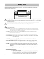
Copyright© ViewSonic Corporation, 2004. All rights reserved. ViewSonic, the three birds logo and OnView are registered trademarks of ViewSonic Corporation. Disclaimer: ViewSonic Corporation shall not be liable for technical or editorial errors or omissions contained herein; nor for incidental or consequential damages resulting from furnishing this material, or the performance or use of this material, or the performance or use of this product. In this interest of continuing product improvement, ViewSonic Corporation reserves the right to change product specifications without notice. Information in this document may change without notice. No part of this document may be copied, reproduced, or transmitted by any means, for any purpose without prior written permission from ViewSonic Corporation. FOR YOUR RECORDS This serial number of this product is on the back of the HDTV receiver. Write the serial number in the space below and keep this guide as a permanent record of your purchase to aid in identification in the event of theft or loss. Model Name: ViewSonic NEXTVISION HD12 Model Number: VS10321-1M Serial Number: Purchase Date: Electronic Warranty Registration To meet your future needs, and to receive any additional product information as it becomes available, please register your warranty on the Internet at http://www.viewsonic.com 1 Safety First Please review the following safety precautions. If this is first time to use a terrestrial TV receiver, then read this manual before installing or using the terrestrial TV receiver. If the receiver is not functioning properly, please contact ViewSonic customer support. WARNING! RISK OF ELECTRICAL SHOCK DO NOT OPEN WARNING: TO REDUCE THE RISK OF ELECTRICAL SHOCK DO NOT REMOVE THE COVER NO USER-SERVICEABLE PARTS ARE INSIDE REFER SERVICING TO QUALIFIED PERSONNEL The lightening symbol in a triangle is used to alert you to the presence of dangerous voltage inside the receiver that may be sufficient to constitute a risk of electric shock to anyone opening the case. It is also used to indicate improper installation or handling of the receiver that could damage the electrical system in the receiver or in other equipment attached to the receiver. The exclamation point in a triangle is used to alert you to important operating and maintenance instructions. Failure to follow these instructions could result in injury to you or damage to the receiver. Be careful with electricity: Power outlet: To prevent electric shock be sure the electrical plug used on the receiver’s power cord matches the electrical outlet used to supply power to the receiver. Connect the power cord only to a power source that operates at 90~260 Volts AC, 50/60 Hz. Power plug: If a three-prong power plug is provided with the receiver, be sure it is used with a properly grounded three-wire power socket. Power cord: Be sure the power cord is routed so that it will not be stepped on or pinched by heavy items. Power overloading: Avoid overloading electrical outlets or extension cords, which otherwise could result in electric shock or fire. Lightening: For protection from lightening, or when the receiver is left unattended for a long period, disconnect it from the power source. Protect other equipment: Unplug the receiver before connecting any other equipment, especially the TV antenna Connect all equipment to the receiver before plugging any power cords to the power source. Power line: Be sure your TV antenna is not located near overhead power lines, or where it might fall into any power lines. Also be careful to avoid touching any such power lines when installing the TV antenna. Antenna Grounding: Be sure that antenna is grounded to provide protection from Lightening and build-up of static electricity. Antenna Installation Instruction: 1. Outdoor Antenna Grounding: If an outside antenna or cable system is concerned to the product be sure the antenna or cable system is grounded so as to provide some protection against voltage surges and built-up static charges, Article 810 of the National Electrical Code, ANSI/NFPA 70, provides information with regard to proper grounding of the mast and supporting 2 2. 3. structure, grounding of the lead-in wire to an antenna discharge unit, connection to grounding electrodes, and requirements for the grounding electrodes. Lightning: For added protection for this product during a lightning storm, or when it is left unattended and unused for long periods of time, unplug it from the wall outlet and disconnect the antenna or cable system. This will prevent damage to the product due to lightning and power-line surges. Power Lines: An outside antenna system should not be located in the vicinity of overhead power lines or other electronic light or power circuits, or where it can fall into such power lines or circuits. When installing an outside antenna system, extreme care should be taken to keep from touching such power lines or circuits as contract with them might be fatal. Also follow these precautions: Ventilation: Do not block the ventilation slots on the receiver, or place any heavy object on top of it. Blocking the air flow could damage the receiver. Arrange components so that air can flow freely around the receiver. Ensure that there is adequate ventilation if the receiver is placed in a stand. Put the receiver in a properly ventilated area, away from direct sunlight or any source of heat. Overheating: Avoid stacking the receiver on top of a hot component such as a power amplifier. Risk of Fire: Do not place the receiver on top of any easily combustible material, such as carpet or fabric. Proper Connections: Be sure all equipment cables are connected to the receiver as described in this manual. Object Entry: To avoid electric shock, never stick anything in the slots on the case or remove the cover. Water Exposure: To reduce the risk of fire or electric shock, do not expose the receiver to rain or moisture. EMI (Electro Magnetic Interference) tested 3 Table Of Content Safety First.................................................................................................................................. 2 Table Of Content.......................................................................................................................... 4 Introduction to NextVision HD12 ................................................................................................... 6 Package Contents ........................................................................................................................ 6 Frond Panel Buttons and LEDs ...................................................................................................... 7 Rear Panel Jacks .......................................................................................................................... 8 HD12 Physical Installation............................................................................................................. 9 Connecting Antennas ................................................................................................................... 8 TV Connection - Analog TV ........................................................................................................... 9 TV Connection - HDTV TV or Monitor (YPbPr)............................................................................... 11 TV Connection - HDTV TV or Monitor (RGB) ................................................................................. 12 TV Connection - HDTV TV or Monitor (DVI with HDCP).................................................................. 13 Video Source Connection ............................................................................................................ 14 Viewing the Remote Control........................................................................................................ 15 Battery Installation..................................................................................................................... 15 MENU Map ................................................................................................................................ 16 Hotkey Map............................................................................................................................... 18 Setting Up The ZAT-500HD RECEIVER ......................................................................................... 19 Channel .................................................................................................................................... 19 Auto Scan ................................................................................................................................. 20 Memorize Channel Manually........................................................................................................ 21 Edit Channel.............................................................................................................................. 22 Caption (Closed-Caption Options)................................................................................................ 23 Setup........................................................................................................................................ 24 Format (Screen Format Setup) .................................................................................................... 24 Aspect Ratio .............................................................................................................................. 25 Sound (Digital Audio Output Setting) ........................................................................................... 26 Opacity (Changing Transparency of On-Screen-Display)................................................................. 26 I-Plate (Changing Display time of the information-Plate)................................................................ 26 Time Zone................................................................................................................................. 27 About (Receiver Information) ...................................................................................................... 27 Lock ......................................................................................................................................... 28 Rating (Lock Programs Using the USTV(FCC) or MPAA) ............................................................... 28 Important information About "Parental Rating" ............................................................................. 29 Change Password....................................................................................................................... 30 Reset Receiver's Data To Default ................................................................................................. 30 Forget the Password? ................................................................................................................. 30 INFO (Information-Plate)............................................................................................................ 31 4 Audio(Select a Multitack Language when Receiving DTV Program) ................................................. 31 MTS (Set Audio when Receiving Analog TV Program) .................................................................... 32 EPG (Electric Program Guide)...................................................................................................... 32 Channel Guide ........................................................................................................................... 32 INPUT (External Video/Audio Input) .......................................................................................... 33 PIP (To watch two channels at the same time) ........................................................................... 33 PIP Position (To Move Small Picture Position in Picture In Picture) .................................................. 34 PIP SWAP (To Swap Big and Small Picture In PIP)......................................................................... 34 POP (Picture On Picture)............................................................................................................. 35 CLOSED CAPTION...................................................................................................................... 35 FAVORITE CHANNEL LIST........................................................................................................... 36 Press Numeric Key to Select Digital Channel ................................................................................. 36 FREEZE the PICTURE ................................................................................................................. 36 APPENDIX 1 DTV Channel Table Information ............................................................................ 38 APPENDIX 2 TROUBLE SHOOTING .......................................................................................... 39 APPENDIX 3 ON SCREEN MESSAGE ......................................................................................... 40 APPENDIX 4 GLOSSARY.......................................................................................................... 41 APPENDIX 5 TECHNICAL SPECIFICATIONS............................................................................... 42 5 Introduction to NextVision HD12 Getting Started Thank you for choosing ViewSonic! Your new NextVision HD12 HDTV receiver is designed to receive free-to-air ATSC terrestrial TV channels. The receiver is operated via the remote control as indicated in the following pages. The receiver also provides a wide variety of options for attaching to your TV and other home entertainment equipment by connector of DVI, RGB, Component Video Y/Pb/Pr, Composite Video (RCA), S-Video, Audio L/R (RCA) and Coaxial SPDIF. If your service provider or system installer has already set up the TV antenna and connected it to the receiver, then you may want to skip this section. However, if you are setting up the system by yourself, please read this section through "Connecting To Audio Video Devices" on page 9 and 10, and be sure you follow all the precautions listed under “Safety First”. Note: Installation procedures for TV antenna and related equipments are not covered in this manual Package Contents Unpack the product and verify that all of the following items are included. Remember to keep the packaging in case you need to return the receiver for service. Examine all the items to ensure that nothing has been damaged during shipment. If any of the items is damaged, please contact ViewSonic before continuing with installation. NextVision HD12 HDTV receiver Remote Control (with 2 AAA batteries) Audio/Video cable with RCA jacks Component video cable (Y/Pb/Pr) Power cable This user’s manual 6 Frond Panel Buttons and LEDs POWER MENU EXIT SELECT Power Press to turn the Receiver ON or OFF. Right arrow button Move the cursor or field in the right direction with in OSD screen. It also can increase volume level if no cursor control is required. Left arrow button Move the cursor or field in the left direction with in OSD screen. It also can lower volume level if no cursor control is required. Up arrow button Move the cursor or field in the upward direction with in OSD screen. It also can select one channel higher than the present channel if no cursor control is required. Down arrow button Move the cursor or field in the downward direction. It also can select one channel lower if no cursor control is required Menu/Select Display the OSD menu on the screen and select highlighted options or values in the menus. Exit Go to the previous OSD menu or exit the main OSD menu. LED Display The display is a 4-digit 7 segments LED display. 7 Rear Panel Jacks OUTPUT SWITCH RF IN DVI (C) RGB/ DVI (V) Y Pb Pr S/PDIF OUTPUT VIDEO L AUDIO INPUT COAXIAL R VIDEO L AUDIO RS-232 AC INPUT 100 ~ 240V 50/60 Hz R 1 DVI HDCP OUT RGB OUT 2 Y Pb Pr S-VIDEO OPTICAL S-VIDEO RF In Connect it with UHF/VHF antenna for terrestrial Digital-ATSC/Analog-NTSC TV signal input Video with Audio L/R In 1 Is used to connect the first Composite Video input source. Video with Audio L/R In 2 Is used to connect with Composite Video input source two. S-Video In with Audio L/R In 1 For connecting Video Source device with S-Video output, its audio input will share with the Video In 1. Coaxial S/PDIF Out Connect it through the coaxial cable with the Dolby Digital compatible A/V Receiver (decoder/amplifier) for Dolby Digital 5.1 channel audio. Optical S/PDIF Out Connect it through the fiber cable with the Dolby Digital compatible A/V Receiver (decoder/amplifier) for Dolby Digital 5.1 channel audio. S-Video Output Connect it with TV monitor’s S-Video input Audio L/R Out Connect them with TV monitor’s Audio L / R input connector RCA jacks. YPbPr Out Connect it with HD or Wide-screen TV monitor’s YPbPr video inputs, and then the Output Switch shall switch to “YPbPr” section. Composite Video Out Connect them with TV monitor’s Video input RCA jacks Output Switch 1. 2. YPbPr: Switch when the YPbPr output is used to connect HDTV or Monitor. RGB/DVI (V): RBG or DVI output is used when connecting with the “VESA Timing” Monitor or TV. 3. DVI (C): RBG or DVI output is used when connecting with the “Component Timing” Monitor or TV. RGB Out Connect it with TV monitor’s RGB input connector, while the Output Switch shall be switched to “RGB/DVI (V)” or “DVI (C) ”position. DVI with HDCP Out Connect them with TV monitor’s DVI input connector, while the Output Switch shall be switched to “RGB/DVI (V)” or “DVI (C) ”position. Note: The Receiver DVI with HDCP output is the one that is compliant with EIA-861 and HDCP specification. Check your TV or monitor’s user manual to find out if the TV or monitor’s DVI is compliant with these specifications, or you cannot see any picture on your TV or monitor. Power Connector AC power input, 100-240V, 50-60Hz. RS-232 For service only. 8 HD12 Physical Installation There are many ways to connect the HD12 Receiver to your home entertainment system, depending on the equipment and connection types you have. However, for the best video/audio quality, use the higher quality Y/Pr/Pr or DVI connections if available. And always remember to disconnect the receiver from the power source prior to connecting or after disconnecting the cable to the UHF/VHF antenna. Before Connecting to other devices When the receiver is connected to the antenna attached with a signal amplifier which requires power supply, be sure the amplifier doesn't have power leakage before connecting the coaxial cable to the receiver. Connecting Antennas Cable or Antenna 1. Connect Antenna to the Receiver RF Input by using a coaxial RF cable. 2. You may connect Cable NTSC signal to the receiver by using a coaxial RF cable. Note: except the terrestrial ATSC signal, the Receiver also could receive the traditional NTSC signal, please note that it could not recognize the digital cable QAM signal to decode. 9 TV Connection – Analog TV Cable or Antenna TV 2 COAXIAL OPTICAL Audio Receiver RF IN S-VIDEO 1. Connect the Antenna or Cable to the Receiver RF Input by using a coaxial RF cable. 2. Connect the “VIDEO OUTPUT” and “AUDIO OUTPUT” to the “A/V IN” jack on your TV by using RCA-type cables. You also could use the S-VIDEO instead of the VIDEO. Uses the S-VIDEO cable to connect the Receiver “S-VIDEO OUT” to your TV “S-VIDEO IN”. 3. If you have the “Home Theater” audio system, connect the “Coaxial S/PDIF” or “Optical S/PDIF” to your “Dolby Digital compatible A/V Receiver” by using the fiber or RCA-type coaxial cable. 10 TV Connection – HDTV TV or Monitor (YPbPr) OUTPUT SWITCH Cable or DVI (C) RGB / DVI (V) Y Pb Pr Antenna OUTPUT SWITCH RF IN DVI (C) RGB / DVI (V) Y Pb Pr OUTPUT VIDEO L AUDIO INPUT S/PDIF COAXIAL R VIDEO L AUDIO AC INPUT 100 ~ 240V 50/60 Hz RS-232 R 1 DVI OUT RGB OUT Y Pb Pr 2 S-VIDEO OPTICAL S-VIDEO TV 1 2 COAXIAL OPTICAL Audio Receiver RF IN S-VIDEO 1. Connect the Antenna or Cable to the Receiver RF Input by using a coaxial RF cable. 2. Connect the “YPbPr OUTPUT” and “AUDIO OUTPUT” to the “YPbPr IN” and “AUDIO IN” jack on your TV by using YPbPr and Audio L/R RCA-type cables. 3. If you have the “Home Theater” audio system, connect the “Coaxial S/PDIF” or “Optical S/PDIF” to your “Dolby Digital compatible A/V Receiver” by using the fiber or RCA-type coaxial cable. Note: when you are using the YPbPr connection, the “OUTPUT SWITCH” must be set toward the “YPbPr” position. 11 TV Connection – HDTV TV or Monitor (RGB) OUTPUT SWITCH Cable or Antenna DVI (C) RGB / DVI (V) Y Pb Pr COAXIAL TV OPTICAL Audio Receiver 1. Connect the Antenna or Cable to the Receiver RF Input by using a coaxial RF cable. 2. Connect the “RGB OUT” and “AUDIO OUTPUT” to the “RGB IN” and “AUDIO IN” jack on your TV by using RGB and Audio L/R RCA-type cables. 3. Connect the “Coaxial S/PDIF” or “Optical S/PDIF” to the “Dolby Digital compatible A/V Receiver” by using the fiber or RCA-type coaxial cable if you have the “Home Theater” audio system. Note: when you are using the RGB connecting, the “ OUTPUT SWITCH” must be set toward the “RGB/DVI (V)” or “DVI (C)” position. The HDTV TV or Monitor RGB signal reception timing setting depends on the manufacture’s setup. However, you could try both of switch position till you could see the Receiver’s picture on TV screen. 12 TV Connection – HDTV TV or Monitor (DVI with HDCP) OUTPUT SWITCH Cable or Antenna DVI (C) RGB / DVI (V) Y Pb Pr COAXIAL TV OPTICAL Audio Receiver 1. Connect the Antenna or Cable to the Receiver RF Input by using a coaxial RF cable. 2. Connect the “DVI OUT” and “AUDIO OUTPUT” to the “DVI IN” and “AUDIO IN” jack on your TV by using DVI and Audio L/R RCA-type cables. 3. Connect the “Coaxial S/PDIF” or “Optical S/PDIF” to the “Dolby Digital compatible A/V Receiver” by using the fiber cable or RCA-type coaxial if you have the “Home Theater” audio system. Note: when you are using the DVI connecting, the “ OUTPUT SWITCH” must be set toward the “DVI (C)” position. The Receiver DVI with HDCP output is the one that is compliant with EIA-861 and HDCP specification. Check your TV or monitor’s user manual to find out if the TV or monitor’s DVI is compliant with these specifications, or you cannot see any picture on your TV or monitor. 13 Video Source Connection 1. You could connect Video source like DVD, VCR, LD or Cable/Satellite Receiver by using the Composite Video or S-Video cable. 2. Connect the “AUDIO OUT” jack on the video source device to the receiver’s “Audio IN” by using Audio L/R RCA-type cables. Note: when you are using the S-VIDEO for connecting the Video-Source-Device to the Receiver, please note that the Receiver’s S-VIDEO audio input is set on the first pair of Audio L/R INPUT RCA jack. 14 Viewing the Remote Control Battery Installation Use two AAA batteries (supplied) Remove battery cover by pushing the tab while lifting the cover up. Install batteries matching (+) and (-) polarity signs. Replace the battery cover. Note: incorrect installation can cause battery leakage and corrosion that will damage the Remote Control. Precautions Replace batteries in pairs. Do not mix battery types (zinc carbon with alkaline). Do not recharge, heat, and short circuit, disassemble, or burn batteries. Button Description Power Numeric Buttons MUTE Press to turn ON and OFF the device Press to enter channel number or password Press to turn off the audio output Press to call up the Closed Caption (CC) and Caption Service (CS) list. You can select one the desired Closed Caption. Press to displays I-Plate, providing information about the current channel, press twice to see the program extend information Press to select multi-lingual Audio soundtracks Press to activate or close the On-Screen Display Press to back to the previous menu page Press to display the Electric Program Guide Press to displays the “ALL”, “Digital”, “Analog” and “Favorite” program list. Press to move highlighted selection through menu or submenus Press highlight menu or submenu item Press to scroll channel up and down. Press to increase or decrease audio volume Press to change the picture resolution between 1920 X 1080i; 1280 x 720p; 720 x 480p; and 720 x 480i video format for YPbPr, RGB or DVI output. Press to adjusts the aspects ratio between 16:9 and 4:3 modes. Press to pause the Picture in Picture Press to change the auxiliary input from Tuner, Video 1, Video 2 or S-Video. Press to display the Picture on Picture Press to display or delete PIP frame Press to change PIP Frame location in PIP mode Press to swap Main picture with PIP frame in PIP mode CC/CS INFO AUDIO MENU EXIT EPG FAV Direction buttons Enter CH+/CH- VOL+/VOL- V. FORMAT A. RATIO FREEZE INPUT POP (Red) PIP (Green) PIP.POS (Yellow) PIP.SWAP (Blue) 1 2 3 4 5 6 7 8 9 0 15 MENU Map OSD Menu Tree Edit Auto Scan Channel Enter Password Manual Scan Channel Lock Setup Favorite Lists Setup (ATSC & NTSC) Scan Ch2~69 Off Air (ATSC&NTSC) Enter Ch Scan Cable STD Enter Ch Scan Cable IRC Enter Ch Scan Cable HRC Enter Ch Scan Default Font Size Small Middle Large Default Style0 Style1 Font Style Style3 Style4 Style5 Style6 Style7 Caption Default Background Red Black Green Font Color Yellow Foreground Pink Light Blue Blue Background Font Opacity Foreground 4/3(ratio) Default Solid Full Translucent Fill Transparent Fill 480i(720x480) 4:3 (Letterbox) 480p(720x480) 4:3(Zoom) 720p(1280x720) 4:3(Full) 1080i(1920x1280) Format 16/9(ratio) 480i(720x480) 16:9 (Pillar box) 480p(720x480) 16:9(Zoom) 720p(1280x720) 16:9(Full) 1080i(1920x1280) Setup Sound Opacity I-Plate Time Zone About Lock Enter Password PCM Dolby Digital 0%~100% adjustment Display Time Time Format Time Adjustment HW & SW version Rating Seconds Setting 2.4.6 sec / off 12 or 24 30min/per MPAA N/A G PG PG-13 16 R NC-17 X None TV-Y TV-Y7 FV TV-G V V TV-PG USTV S L D V TV-14 S L D V TV-MA S L Password Enter Password Reset Box Confirm Reset Confirm New New Password Password Reset 17 Hotkey Map Item 1 Name POWER Hot Key Function On OFF OFF(default) CC1 2 CC/CS (Closed Caption) CC2 CC3 CC4 3 MUTE Press to turn-off /on audio output 4 #0~#9 Numerical keypad (Channel Number) 5 AUDIO Language 1(ATSC) Language 2(ATSC) Language 3(ATSC) Displays I-Plate providing information about the current channel 6 INFO. 7 FAV. Display the favorite channel list. (MAIN+ATSC+NTSC+FAV. ) 8 EPG Press to display the Program Guide window, press again could show the Channel Guide window 9 MENU 10 CH ▲CH▼ 11 VOL +VOL - Activates or turn off the On Screen Menu Control the channel up/down Control the volume increase/decrease Format:480i 12 V. Format Format:480P Format:720P Format:1080i 4:3 (LetterBox) 4:3 (Pan&Scan) 13 A.RATIO 4:3 (Crop) 16:9 (PillarBox) 16:9 (Pan&Scan) 16:9 (Crop) 14 FREEZE Freezes the picture on the main screen PIP-OFF C-Video 1 15 PIP(Green) C-Video 2 S-Video DigitalTV1 DigitalTV2 Up 16 PIP.POS Down Left Right 17 PIP.SWAP 18 MTS (Audio Key in receiving analog TV) Swap between Main Video window and PIP1 Video window Mono 19 POP(Red) 20 Timing Switch (HW) Stereo Sap Displaying a current selected channel program surrounding by 8 sub-pictures. Component/VESA Timing on RGB & DVI output TV mode 21 INPUT C1-Video C2-Video S-Video 18 Setting Up The HD12 RECEIVER 1. Make sure the physical connection is properly connected. 2. Switch on the TV. 3. Select the appropriate external video input on your TV by using the TV remote control. 4. Select the appropriate video output on the Receiver by using the Receiver video output switch. 5. Make sure the receiver is already in power-on mode. If it is in off mode (i.e. front panel shows ----), switch on the receiver by pressing the “POWER” button on the front panel of the receiver or on the remote control. 6. If the box is moved to a different location. You should reset the box to factory default (Page 31) and do the channel scanning all over again. Press the “MENU” button to see the Menu banner. Channel Before you can use any of the channel buttons (CH ▲▼, FAV.), the available channels must first be scanned and memorized. Initial Screen – ● The first time when the receiver is powered on, you will see a message block of “Press (Menu) key and then select Channel to run Auto/Manual Scan”. Press the MENU button to display the MENU banner. ● Use the arrow keys ◄ or ► to move highlight through the menu banner, the highlight icon will lead to show those second layer function items. ● Press “EXIT” button will return to the previous menu or press “MENU” key to directly leave the menu. 19 Auto Scan The steps required to program the receiver are outlined as below: ● Press ◄ or ►keys to move highlight to the CHANNEL and enter default password “0000” to show three sub-menus, 1. Edit 2. Auto Scan 3. Manual Scan ● Press ▲ or ▼ buttons to highlight the AUTO SCAN, and then press ENTER to Launch the auto scan. An AUTO-SCAN window will show the SCAN status. ● The receiver starts Off-Air channel. It will search both NTSC analogue and ATSC digital signal from channel 2 up to channel 69. The percentage bar shows the progress being made. ● Once the digital TV signal is scanned, the channel number and program name will be shown on the “Scan List”. ● It takes a few minutes to complete the whole scanning process. ● Scanning will end up on channel 69, When it is complete (even in processing) you can press “EXIT” key to leave this window and enjoy watching DTV programs. 20 Memorize Channel Manually ● On the Channel menu page, select the third item “Manual Scan”, and then use the ◄ or ► button to select the channel plan. ● Press Enter to highlight the input column. Then press numeric buttons to input the channel number. The channel frequency will be automatically showing on right side of the input column. ● Press Enter button when the message “Add channel” and “press Enter to add channel” has shown. ● If the ATSC signal is found and locked, the Status will show message “Get No.XX 8VSB channel success”. Then you can press EXIT or Menu to leave the menu page and watch the program, or go ahead scanning the other channels. ● If the signal is not locked, the status will show “Got No Channel”. You can scan the signal again or refer to the signal level bar “Signal” for aligning the direction of the antenna to get the signal. ● When the signal is locked and the receiver is on the channel, you can enter into this page to check the signal level. Note : It’s suggested that you contact the antenna Installer when you have to troubling with locking the signal. ● Press EXIT button to back to the main menu or press MENU button to leave. 21 Edit Channel ● On the “Channel” menu, press the numeric key to input the default password “0000” or user password to show the sub-menu. Press ▲ and ▼ to highlight the Edit, and then press Enter. ● Press ▲▼ and◄ ► buttons to highlight the channel’s BLOCK or FAV control column and press ENTER to block channel or copy channel into the favorite channel list “F1”. ● After the edit setting, press the EXIT button, then it will pop up a confirmation window, 1. Press ENTER key on “NO” to cancel the change. 2. Highlight “YES” and press ENTER to save the settings. NOTE: When the blocked channel has selected, the program can not be showed, and you will get the message ”Channel is blocked” from TV screen. 22 Caption (Closed-Caption Options) Press the MENU button on the remote control. ● Press ◄ ► buttons to highlight “Caption” icon and press ENTER. Font Size: ● Press ◄ ► and ▲▼ buttons and the ENTER button to select desired Closed Caption font size. Font Style: ● Press ◄ ► and ▲▼ buttons and the ENTER button to select desired Closed Caption font style. Closed Caption Background Color: ● Press ◄ ► and ▲▼ buttons and the ENTER button to select desired Closed Caption background color. Closed Caption Foreground Color: ● Press ◄ ► and ▲▼ buttons and the ENTER button to select desired Closed Caption font color. Closed Caption Background Opacity: ● Press ◄ ► and ▲▼ buttons and the ENTER button to select desired Closed Caption background opacity. Closed Caption Foreground Opacity: ● Press ◄ ► and ▲▼ buttons and the ENTER button to select desired Closed Caption foreground opacity. ● Press EXIT button to back to the main menu or press MENU button to leave. 23 Setup Press MENU and ◄ ► buttons to highlight the “Setup” menu to show its sub-menus, 1. Format 2. Sound 3. Opacity 4. I-Plate 5. Time Zone 6. About Format (Screen Format Setup) ● From the “Screen” menu, press ▲▼ buttons to highlight the “Format” and press ENTER. ● Press ▲▼and◄ ► buttons to select your TV type, video resolution and aspect ratio. ● Press EXIT button to back to the main menu page or press MENU button to leave. Note: You can also change the picture resolution or TV Fomat by pressing the “V.Format” and “A.RATIO”button on the remote control. 24 Aspect Ratio Your options in the Screen Format menu depend on the type of TV or monitor you are using with the Receiver. ● 4:3 (Letterbox): Select this when receiving a 16:9 source signal and you want to see the original 16:9 format. Blank panels will appear at the top and bottom of the screen. ● 4:3 (Zoom): Select this wills no blank panels will be added. ● 4:3 (Full): Select this when receiving a 16:9 image and you want the wide movie format to fill the entire screen. ● 16:9 (Pillar box): Select this when receiving a 4:3 source signal and you want to see the original 4:3 format. Blank panels appear at the left and right of the screen. ● 16:9 (Zoom): Select this wills no blank panels will be added. ● 16:9 (Full): Select this when receiving a 16:9 image and you want the wide movie format to fill the entire screen. 4:3 TV or Monitor: SOURCE SIGNAL 4:3 TV FORMAT LETTER BOX FULL ZOOM 3 4 9 16 16:9 TV or Monitor: SOURCE SIGNAL 16:9 MONITOR FORMAT PILLAR BOX FULL ZOOM 3 4 9 16 25 Sound (Digital Audio Output Setting) The digital channel’s sounds can be output from the rear-panel S/PDIF connectors of your receiver. The digital sound outputs are either optical through or coaxial connectors. After connecting an optical or a coaxial digital-audio component, you must specify the transmission format (Dolby Digital or PCM). ● Press Enter on Sound to show the audio format option, you can press ◄ ► buttons to highlight the desired audio format, and then press Enter to confirm the setting. ● Press EXIT button to back to the main menu or press MENU button to leave. Opacity proper (Changing Transparency of On-Screen-Display) ● Press ▲▼ buttons to highlight the Opacity and press Enter. ● Use the ◄ ►buttons to change the percentage of the On-Screen-Display’s transparency. ● Press EXIT button to back to the main menu or press MENU button to leave. I-Plate (Changing Display time of the information-Plate) ● Select the I-Plate, you can press ◄ ► and ▲▼ buttons to change the Information-Plate display time to 2, 4, 6 seconds or off mode. ● Press EXIT button to back to the main menu or press MENU button to leave. 26 Time Zone ● Press ▲or▼ buttons to highlight TIME ZONE from the Setup menu and press ENTER. ● As you have received a digital signal, the receiver’s time will be set automatically. ● Press the ◄ or ► buttons to change time display format between 12 and 24. ● Press the Enter buttons to highlight the input column, and then press ◄ or ► buttons to change time zone (increase or decrease 30 minutes when press the arrow key every time). ● Press EXIT button to go back to the main menu or press MENU button to leave. About (Receiver Information) ● Under Setup’s sub-menu, you can select item “About” to check the hardware and software version. ● Press▲ or ▼ buttons to highlight About and press ENTER button to see the information window. ● Press EXIT button to back to the main menu or press MENU button to leave. 27 Lock Rating (Lock Programs Using the USTV(FCC) or MPAA) Press the MENU button on the remote control. ● Press ◄ ►buttons to highlight “Lock” icon and press ENTER to show the enter password column. ● Enter the password correctly. ● After the password is entered, the screen will display three sub-menu, 1. Rating 2. Password 3. Reset Box ● Press ▲▼ buttons to highlight the “Rating”, and then press Enter to into the rating control menu. This menu lists both MPAA and USTV (FCC) Parental ratings. You can independently lock the MPAA and TV ratings. The locked ratings are indicated by the lock symbol. ● Press ▲▼ and◄ ► buttons and the ENTER button to activate the appropriate restrictions for either MPAA rating system or USTV(FCC) rating system. ● Press EXIT button to back to the main menu or press MENU button to leave. NOTE: When the rating locked channel has selected, the program cannot be showed and you will get the message ”Program is rating blocked” from TV screen. 28 Important information About “Parental Rating” Explanation of the MPAA and TV (FCC) Rating Systems: USTV (FCC) Age-Based Ratings TV-MA Mature audiences only. This program may contain mature themes, profane language, graphic violence and explicit sexual content. TV-14 Parents strongly cautioned. This program may contain sophisticated themes, sexual content, strong language and more intense violence. TV-PG Parental guidance suggested. The program may contain infrequent coarse language, limited violence, some suggestive sexual dialogue and situations. TV-G General audience. It contains little or no violence, no strong language, and little or no sexual dialogue or situations. TV-Y7 Directed to older children. Themes and elements in this program may include mild physical or comedic violence, or may frighten children under the age of seven. TV-Y All children. The themes and elements in this program are specifically designed for a very young audience, including children from ages two – six. USTV (FCC) Content Category V Violence. L Offensive language. FV Fantasy or cartoon violence. S D Sexual content. Dialogue...sexual innuendo. MPAA Rating System (Movies) G General audience. No restriction. PG Children under 13 should be accompanied by an adult. PG-13 Parental guidance suggested. Children under 13 should be accompanied by an adult. R Restricted. Viewers should be 17 or older. NC-17 Not classified. Viewers should be 17 or older. X Adults only. * USTV (FCC) ratings: The particular rating that you have selected will be locked (and indicated as a green lock symbol). Also, all of the age-based ratings will be locked within the particular group. Suppose that the TV-G rating and all of its contents (V, S, L, and D) are locked. In that case, more restrictive ratings (TV-PG, TV-14, and TV-MA) and all of their contents (V, S, L, and D) are automatically locked as well. * MPAA ratings: The particular rating that you have selected will be locked. In addition, more restrictive ratings will be locked as well. * Neither USTV (FCC) ratings nor MPAA ratings apply to news programs. 29 Change Password Please be noted that the access right of “Lock”, “Channel” menu functions are all controlled by the Password. You need to input the correct password to enter these functions. ● Press the MENU button on the remote control. ● Press ◄ or ► buttons to highlight the Lock icon. Then press ▲or ▼buttons to highlight the Password and press ENTER. ● Follow the description on the pop-up window to press numeric buttons to input the new and confirm new password. ● Press EXIT button to back to the main menu or press MENU button to leave. Reset Receiver’s Data To Default The “Reset Box” function allows resetting HD12 Receiver back to factory default status. ● On the “Lock” page, press ▲or ▼ buttons to highlight the Reset Box, then press Enter, there will pop up the RESET confirmation message “Press Yes will reset box to default value”, 1. Press ENTER on “Yes” to process. 2. Use ◄ or ► keys to highlight “NO” and press ENTER to cancel. ● Press EXIT button to back to the main menu or press MENU button to leave. Forget the Password? You must reset the Receiver to back to the default status if you forget the password. Please be noted that you will lose all your setting when the Receiver has reset. ● Turn off the Receiver and press the “POWER” button on the front panel or on the remote control. When the front panel LED display “boot”, and then press the front panel button “▲”, “ ▼”, “◄” and “ MENU-SELECT” in sequence. The Receiver will be reset to default status automatically. ● Uses the default password “0000” to enter the Menu item which requires the password. ● You have to do the channel scan as you turn on the Receiver for the first time (see page.20). 30 INFO (Information-Plate) When you are watching the DTV channels and want to learn the current program name and relevant information, you can press “INFO” button to show I-Plate on screen. Current EPG ● after pressing INFO button, the I-Plate will pop up including information as follows, - TV Station Name - Current Channel Number - Current Local Time - Program Name - Program start and end time - Picture resolution - Closed Caption - Audio System (Dolby 5.1 or PCM) - Program Rating Information NEXT EPG ● you can press the ► button, the I-Plate status will change to show the NEXT program’s information. Press the ◄ button could return to the Current status. Extended Program Information ● When the Current or Next status I-Plate is still on the TV screen, press the INFO button again will call up the extended program information of the current TV channel. ● Press INFO button again to cancel the I-Plate or Extension window, or you can press EXIT button to leave. Note: Be sure the receiver leaves the main menu of On Screen Display and is tuned to a TV channel when you press “INFO”. Audio(Select a Multitack Language when Receiving DTV Program) ● Press the AUDIO button to display Multi-language window. ● Use ▼ ▲ keys to highlight the language you want and press ENTER button to change it. ● Press EXIT button to back to the main menu or press MENU button to leave. 31 MTS (Set Audio when Receiving Analog TV Program) ● Press the AUDIO button in sequence could change Receiver audio output status to “MONO”, “STEREO” or “SAP” when watch the NTSC TV channel. ● Press EXIT button to back to the main menu or press MENU button to leave. EPG (Electric Program Guide) ● Press the EPG button to display EPG window. ● The current program will be highlighted yellow color automatically. ● Press ◄ ►or ▲▼ buttons to roll program list toward right to see maximum 12 hours program guide. Channel Guide ● Press EPG buttons again when in the EPG window, you can see the channel list guide. Press ▲or ▼ buttons to roll Channel list toward up or down. 32 INPUT (External Video/Audio Input) ● When you are watching DVD programs from AUX IN (2 Composite Video In/ 1 S-Video and 2 pairs of Audio Left/Right In connectors on the receiver’s back panel), you can press INPUT button to select TV, Composite Video 1, Composite Video 2, S-Video signal input. ● Press V.FORMAT button can upscale the picture resolution to 480p, 720p or 1080i. PIP (To watch two channels at the same time) ● When you are watching the terrestrial or cable TV programs, you can press PIP button on the remote control to show the multiple programs on TV screen. ● Press “PIP” button on the remote control, you can get the PIP PROGRAM list containing all digital TV programs within the same RF channel (for instance, channel KTRK-SD) and auxiliary signal input: Composite Video and S-Video. Use ▲ and ▼ keys to highlight the desired source signal and press ENTER button , then you can watch this Digital TV program by PIP, which is in the small screen on the right bottom side of the screen. ● Press EXIT or PIP button can cancel the PIP menu window. ● Use ▲ and ▼ keys to browse through the PIP Program lists. ● Highlight the program and press ENTER key to get the Picture In Picture– two programs on the TV screen at the same time. ● You can press the EXIT button or highlight the PIP OFF and press ENTER to close the PIP function. ● To close the small screen you can press the PIP button again or press EXIT button. 33 PIP Position (To Move Small Picture Position in Picture In Picture) ● When in PIP mode, you can press the PIP.POS button to move small picture position to center, up right, downright, down-left or up-left. PIP SWAP (To Swap Big and Small Picture In PIP) ● When in PIP mode, you can press the PIP.SWAP button to swap big and small picture. ● To close the small screen you can press the PIP button again or press EXIT button. 34 POP (Picture On Picture) ● When you are watching terrestrial or cable TV channels, you can press “POP” button on the remote control to call up the POP screen. ● You can get a current selected channel program surrounding by 8 sub-pictures. The sub-pictures are all digital TV programs within the same RF channel. ● To close the POP screen, you can press the POP button again or press EXIT button. CLOSED CAPTION ● When you learn from the I-PLATE that there is Closed Caption data on the current channel, you can press CC/CS button on the remote control to display C.C. Option list it on the TV screen. ● Use ▲ and ▼ keys to highlight the desired CC signal and press ENTER button. ● After the type of Closed Caption has selected, press EXIT or CC/CS key to cancel the CC Option list , then you can watch this Digital TV program with Closed Caption. 35 FAVORITE CHANNEL LIST ● When you are watching terrestrial or cable TV channels, you can press “FAV” button on the remote control to call up the Favorite List. ● Use ◄ and ► keys to navigate “ALL”, “ATSC”, “NTSC” and “FAV” program lists. ● Use ▲ and ▼ keys to browse through the selected program lists and highlight the program you like to watch, then press ENTER button. Press Numeric Key to Select Digital Channel For the digital channel number is different with the traditional NTSC channel number. Please follow below indication to select the digital channel if you prefer to use numeric key to do the channel selection. Example: digital channel number: 10 - 2 1. press numeric key “1” and “0” 2. press “► “buttons 3. press numeric key “2” FREEZE the PICTURE ● Press the “FREEZE” button on the remote control to freeze the main window picture. A remain message “Freeze” will be shown on up-right of the display screen. ● You can press the “FREEZE” button again to release the picture. Note: If you freeze a program for purposes other than personal viewing, you may infringe on the copyrights that the program may be under. 36 APPENDIX 1 DTV Channel Table Information *Log on to the website http://www.antennaweb.org and select “Choose An Antenna”, enter your address and find the DTV stations airing the EDTV/HDTV signal you can receive. Then visit the local station’s website for program schedules. Usually the website name is the same as the station’s name. For example, DTV station WCBS (channel 56) New York’s website is http://www.wcbs.com and KCET (UHF channel 59) Los Angeles’s website is http://www.kcet.org. However, the most accurate method for locating the local station’s website is through their original network, for example, to find WCBS New York through the associated network CBS’s website. You can also contact the network services center for detailed information about their local DTV program package. Note : (a) By utilizing the website Antenna Web you can also get information on choosing the correct antenna type and its positioning to the DTV station you want to watch. (b) NAB (National Association of Broadcasters) has updates on the local DTV stations in operation at http://www.nab.org/Newsroom/Issues/digitaltv/DTVstations.asp 37 APPENDIX 2 TROUBLE SHOOTING Problem Solution (1) The receiver front panel power (a) Check the main lead and make sure the power plug is indicator (red LED) doesn't light up, well plugged into a stable power outlet and no message on the front panel (b) Press "Power" button on the front panel to see if the red light display (power indicator) is on. (2) Has message on the front panel but (a) Press button "Menu" on the remote control or front panel to no picture on your TV screen call up On Screen Display (b) Make sure the connector type between set top box and your TV set matches each other. For instance, if you use RCA or S-Video connector you may choose the same external video input RCA or S-Video mode in TV set. (c) Be sure you have done the channel scan before you watch the TV program. (3) Poor picture quality (a) Check the antenna and make sure it is aligned to the correct direction. Use receiver's "Manual Scan" page to check the signal's RF Level when aligning the antenna. (b) If you use any kind of amplifier to boost the signal level, please check whether it works well, and ask help from the antenna installer. (c) Refer to solutions in item (2) above (4) No audio service (a) Check the receiver and your TV's volume are properly set and not in "mute" mode. (b) Check the audio connectors are correctly and firmly connected (c) Make sure the receiver switch to the correct Audio mode: AC-3 or PCM (MPEG/Analog Audio). (d) Scan this channel again by using "Manual Setup" and see if the audio service will come back. (e) Check with the local TV stations. Sometimes they are just testing new services on their TV or Radio channels. (5) No video service (a) Check the receiver output and your TV's input are properly set. (b) Check the Video connectors are correctly and firmly connected (c) Scan this channel again by using "Manual Installation" and see if the video service will come back. (d) Check with the local TV stations. Sometimes they are just testing new video services on their channels the video service may stop every once in a while. (6) Does not have all the channels (a) Try "Manual Setup" to scan these missing channels. Once the available after using "Auto Scan” receiver picks up the signal, all the transmission parameters when first time installing the will be stored in receiver's memory automatically. receiver. (7) Cannot lock signal by using "Manual (a) Check the channel number is correct according to the channel Setup” table and updated channel table information on Appendix 1 (8) No Closed Caption (a) Make sure the channel you are watching carries closed caption information. (b) Press CC/CS button on the remote control to double check there’s closed caption data output. (9) Cannot receive channels after (a) Reset the Receiver, then use "Auto Installation" or "Manual moving the receiver between cities Installation" to scan through all the channels again. (For instance from New York to Los Angeles) 38 APPENDIX 3 ON SCREEN MESSAGE Message (1) Bad or No Signal (2) (3) (4) (4) (5) (6) (7) (8) (9) Solution (a) Check the antenna cable is connected correctly and firmly to the receiver. (b) Check the digital channel whether it is out of service or not. NTSC Channel not Support POP This message shows when you press the POP on watching NTSC channel. NTSC Channel not Support PIP This message shows when you press the PIP on watching NTSC channel. PIP cannot open since P.G. has been The channel could not be PIP when the parental rating has been set setup. Cancel the Rating setting in Lock menu if you like to see the PIP picture. AUX Source not Support PIP The Receiver could not do the PIP when you watching auxiliary video input as C-Video 1, C-Video 2 or S-Video. Updating Channel Database This message shows when the channel content has changed by TV station or system operator. The Receiver is updating the channel database. Program is rating locked This message shows the program is controlled by the Rating setup. The user is not allowed to see it. Please see page Rating setup. Channel is blocked This message shows when the channel is blocked in Channel Edit menu. Press (Menu) key and then select This message shows on the first time the receiver is powered on, the Channel to run Auto/Manual Scan available channels must first be scanned and memorized. TV SET/Monitor dose not support The message shows your TV or Monitor’s DVI input does not support HDCP, simultaneous RGBHV output the HDCP (Copy Protection), and it suggest you to remove the DVI is affected too, please removes DVI connection. cable connection. HOW TO CONTACT US ViewSonic Corporation Please call us at (800)688-6688 or email us at [email protected] http://www.viewsonic.com 39 APPENDIX 4 GLOSSARY * Aspect Ratio : It is the ratio of the width of the screen to the height. The two relevant digital TV formats are 16:9 (wide screen) or 4:3 (the traditional screen ratio). 16:9 is more ergonomically suitable for human's eye. * Bandwidth : Frequency range allows for carrying a certain radio signal. The speed of data transmission depends on the available bandwidth of the transmission channel. * Coaxial Cable : A type of cable used to transmit high frequency signals e.g. from the VHF/UHF antenna to the terrestrial Digital TV receiver. * Composite Video : There are three elements of the video system : First - the " active video" which means the picture to be displayed on the screen and its associated colors. Second - the " sync" decides where to place each pixel on the screen. Third - the " blanking" tells the display when to turn off the electron beam so no retrace across the screen. These three elements combined together is called " composite video" when connecting to a display through connectors. * ATSC: Abbreviation for "Advanced Television System Committee". The Advanced Television Systems Committee, Inc. (ATSC), is an international, non-profit membership organization developing voluntary standards for the entire spectrum of advanced television systems. They stipulate the standard for terrestrial Digital TV broadcast which is also called ATSC. * EPG : Abbreviation for "Electronic Program Guide". A software that enable viewers to navigate through the large number of channels offered by digital TV broadcaster and select the desired services. * Frequency : The property of a signal which is measured in cycles per second(=Hertz). * Letterbox : The picture with aspect ratio 16:9 in a 4:3 TV screen with blank lines on top and bottom. It is the means to watch a wide screen TV program on a 4:3 TV screen. * Megahertz (MHz) : Millions of cycles per second, which describes frequencies of radio wave or electric current. * OSD : Abbreviation of "On Screen Display", used in digital set top box. OSD is comprised of a main menu and many submenu with lots of options of functions inside. * NTSC : Stands for "National Television System Committee”, the U.S. video standard which includes the image format of 4: 3, 525 horizontal lines (only 480 lines active among them, 60 Hz and a total 6 MHz channel width. * PID : Stands for "Packet Identifier". It is a code used for identifying video, audio PCR and other elements that form a particular service in the transport stream. * RF Channel : Radiated Frequency Channel, one RF channel may carry 4 to 6 sub-channels 2-1,2-2,2-3.etc. * S-Video (also called Y/C) : The standard for the way a video signal is carried on the cable. Y represents brightness and C represents color. S-Video cables have separate wires for the color and brightness so it offers a better picture quality than the composite video. * VHF : Stands for "Very High Frequency", starts from 30 to 300 MHz corresponding to channels 5-12,including Bands I, II and III. * UHF : Stands for "Ultra High Frequency", starts from 300 to 3000 MHz corresponding to channels 28-69, including Bands IV and V. * YPbPr : Component Video Output. It is better than S-Video and Composite Video output in terms of picture quality. YPbPr is the standard HDTV connector. 40 APPENDIX 5 TECHNICAL SPECIFICATIONS Standards Compliance Compliant Standard ATSC Tuner Input Frequency Bandwidth Connector Demodulator 54 ~ 864 MHz 6 MHz F-Type Female 8-VSB Video Output Formats Aspect Ratio Picture Resolution Output System Socket MP @ ML & MP @ HL 4:3 , 16:9 1920 X 1080i; 1280 x 720p; 720 x 480p; 640x480i ATSC HDTV/ NTSC DVI-HDCP/ RGBHV/ YPbPr/ S-Video/ RCA Video Input Format Connector Composite Video x2 / S-Video x1 RCA jack/ Mini Hosiden Socket Audio Output Formats Sample Rate Mode Connector Dolby Digital; MPEG (I & II) 32 / 44.1 / 48 KHz Mono / Stereo / Dual Optical S/PDIF; Coaxial S/PDIF Audio Input Sample Rate Connector 32 / 44.1 / 48 KHz RCA jack Front Panel IR Receiver Function Control Channel Display Yes 7 Keys 4 Digits / 7-segment display Rear Panel I/0 ports 1 Tuner input 2 set of RCA audio port input (L/R) 1 set of RCA audio port output (L/R) 1 set of Fiber S/PDIF audio port output 1 set of Coaxial S/PDIF audio port output 2 set of RCA Video port input 1 set of RCA Video port output Power Supply Input Voltage Consumption (max.) Dimension Size (W x D x H) Weight 1 1 1 1 1 1 1 set set set set set set set of of of of of of of S-Video port input S-Video port output YPbPr Video ports output RGBHV Video ports output DVI with HDCP Video ports output RS-232 data ports power socket 90~240 VAC, 50/60 Hz 30 W 360× 282 × 79 mm 2 Kg (Unpacked) Environmental Data Operating Temperature Storage Temperature 5°~ 40℃ -40 ~ 65℃ *Specifications are subject to change without notice. 41