1
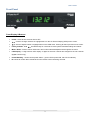
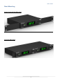
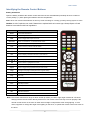
USERS GUIDE V-Tune Pro 4K User Guide Worldwide 4K ATSC/QAM/DVB/NTSC/PAL/IP Tuner i Manual Number: 150129 Firmware: DTB12B290151291 & above User Guide SAFETY INSTRUCTIONS Please review the following safety precautions. If this is the first time using this model, then read this manual before installing or using the product. If the product is not functioning properly, please contact your local dealer or Aurora for further instructions. The lightning symbol in the triangle is used to alert you to the presence of dangerous voltage inside the product that may be sufficient to constitute a risk of electric shock to anyone opening the case. It is also used to indicate improper installation or handling of the product that could damage the electrical system in the product or in other equipment attached to the product. The exclamation point in the triangle is used to alert you to important operating and maintenance instructions. Failure to follow these instructions could result in injury to you or damage to the product. Be careful with electricity: Power outlet: To prevent electric shock, be sure the electrical plug used on the product power cord matches the electrical outlet used to supply power to the Aurora product. Use only the power adapter and power connection cables designed for this unit. Power cord: Be sure the power cord is routed so that it will not be stepped on or pinched by heavy items. Lightning: For protection from lightning or when the product is left unattended for a long period, disconnect it from the power source. . Also follow these precautions: Ventilation: Do not block the ventilation slots if applicable on the product or place any heavy object on top of it. Blocking the air flow could cause damage. Arrange components so that air can flow freely. Ensure that there is adequate ventilation if the product is placed in a stand or cabinet. Put the product in a properly ventilated area, away from direct sunlight or any source of heat. Overheating: Avoid stacking the Aurora product on top of a hot component such as a power amplifier. Risk of Fire: Do not place unit on top of any easily combustible material, such as carpet or fabric. Proper Connections: Be sure all cables and equipment are connected to the unit as described in this manual. Object Entry: To avoid electric shock, never stick anything in the slots on the case or remove the cover. Water Exposure: To reduce the risk of fire or electric shock, do not expose to rain or moisture. Cleaning: Do not use liquid or aerosol cleaners to clean this unit. Always unplug the power to the device before cleaning. ESD: Handle this unit with proper ESD care. Failure to do so can result in failure. FCC This device complies with Part 15 of the FCC Rules. Operation is subject to the following two conditions: (1) This device may not cause harmful interference. (2) This device must accept any interference received, including interference that may cause undesired operation. Trademarks All trademarks in this document are the properties of their respective owners. i User Guide TABLE OF CONTENTS PACKAGE CONTENTS ............................................................................................................. 1 INTRODUCTION ....................................................................................................................... 2 About ..................................................................................................................................................... 2 Features ................................................................................................................................................ 2 Front Panel ........................................................................................................................................... 3 Rear Panel ............................................................................................................................................ 4 Rack Mounting ...................................................................................................................................... 5 Identifying the Remote Control Buttons ................................................................................................ 6 APPLICATION ........................................................................................................................... 7 OPERATION .............................................................................................................................. 8 SETTING UP THE TUNER ........................................................................................................ 8 Channel Setup ...................................................................................................................................... 8 Auto Scan .......................................................................................................................................................... 8 Manual Scan ...................................................................................................................................................... 9 IP Program Setting............................................................................................................................................. 9 Edit..................................................................................................................................................................... 9 Caption (Closed-Caption Options) ...................................................................................................... 11 Setup ................................................................................................................................................... 12 Output Resolution ............................................................................................................................................ 12 OSD Opacity .................................................................................................................................................... 12 I-Plate .............................................................................................................................................................. 12 Power Saving ................................................................................................................................................... 12 Time Zone ........................................................................................................................................................ 12 Sound .............................................................................................................................................................. 12 Network Settings .............................................................................................................................................. 13 System ............................................................................................................................................................. 13 Resetting to the factory defaults ...................................................................................................................... 13 Software Upgrade ............................................................................................................................................ 13 Parental Control Setting ...................................................................................................................... 14 Explanation of the MPAA and TV Rating Systems ........................................................................................... 14 Parental Control ............................................................................................................................................... 15 Advanced Rating.............................................................................................................................................. 15 Change Password............................................................................................................................................ 15 CONNECTOR PIN DEFINITION .............................................................................................. 16 ii User Guide HDMI ................................................................................................................................................... 16 CAT5e/6/6A ......................................................................................................................................... 16 APPENDIX 1 DTV Channel Table Information .................................................................. 17 APPENDIX 2 RF System Guidelines ................................................................................. 18 APPENDIX 3 Troubleshooting........................................................................................... 20 APPENDIX 4 RS-232/LAN Control Protocol ..................................................................... 21 APPENDIX 5 Technical Specifications ............................................................................. 24 APPENDIX 6 Glossary ....................................................................................................... 26 APPENDIX 7 Warranty ....................................................................................................... 28 iii User Guide PACKAGE CONTENTS Please make sure the following items are included within your package. Contact your dealer if any items are missing or damaged. Tuner x 1 Remote Control (with 2 AAA batteries) x 1 Power adaptor x 1 Rack Mount Bracket x 2 Screw x 4 Note: Go to www.auroramm.com for latest manual and firmware 1 User Guide INTRODUCTION About The V-Tune Pro 4K delivers a total Ultra High Definition worldwide tuning solution for any integrated system which requires IPTV, ATSC, QAM, NTSC & PAL. The tuner is capable of decoding MPEG2, MPEG4, VC-1, H.264, and H.265 with resolutions up to 4K2K @ 60Hz via RF and LAN. The V-Tune 4K is integrator-friendly with IR, RS-232 and IP-based control. The video outputs are HDMI 2.0 for the latest connectivity and composite/YPbPr video for legacy. Audio is provided with unbalanced stereo RCA connections, S/PDIF, and optical. The V-Tune Pro 4K defines versatility as it can be fit into nearly any integrated system topology. There is no other tuner on the market which can support all these features at a cost effective price. Features IPTV (UDP/RTP/RTSP Multicast and Unicast) ATSC / QAM / NTSC / PAL / DVB / ISDB-T Worldwide Digital Ultra High Definition Tuning NTSC & PAL Analog Tuning H.265, H.264, MPEG 4, MPEG2, and VC-1 up to 4K2K HDMI 2.0, Composite, and YPbPr Outputs Resolutions: 480i, 480p, 720p, 1080i, 1080p, 4K (UHD), 4K2K (4096x2160 @ 60Hz) Stereo L/R, S/PDIF, and Optical Audio Outputs Dolby Digital Surround Sound OSD Menus, Closed Captioning, V-Chip, & EPG 1RU Single/Dual Rack Mount Ears and IR Remote Included RS-232 / LAN / IR Remote Control Firmware Upgradeable and Cloning via USB port or LAN Built in Web Page Remote Control 2 User Guide Front Panel Front Display & Buttons Power - Press to turn the tuner ON or OFF. - Press to change channels or highlight items on the On-Screen Display (OSD) menu screen. - Press to adjust volume or highlight items on the OSD menu. Press to exit to previous menu screen. Factory Default - Hold simultaneously for 5 seconds to reset system to default settings and reboot. Menu / Enter - Press to launch OSD menu and confirm selected adjustments throughout the menu. LED Display – 5 digit numeric LED display: 3 digits for the main channel and 2 digits for the sub channel (digital sources only). Power/Stand by - shows current power status – green LED for power ON, red LED for stand by IR - blinks to confirm that commands from the remote control are being received. 3 User Guide Rear Panel Rear Connections DC IN - Connect the supplied 12V / 2A power adapter's output. RF IN - Connect a VHF/UHF/ATSC coaxial RF antenna cable to this port for signal input. RS-232 - Connection for remote control via external system (e.g. PC).(see Appendix 3) IR IN - Connection for external IR extender. S/PDIF OUT - Digital audio outputs (optical and RCA type) for connection to external digital audio system. YPbPr - Analog hi-res component video for connection to legacy audio/video switchers or displays. VIDEO - Analog composite video output for connection to legacy audio/video switchers or displays. AUDIO L/R – Analog stereo line level right and left outputs. HDMI 2.0 OUT - HDMI output comprised of digital video and audio signals, for connection to compatible displays or switching/routing devices. USB - Alternate method for installing firmware updates and cloning. LAN - RJ-45 Ethernet port (10/100/1000Mbps) for used for control, IPTV input and firmware updates. (see Appendix 3) Caution: DO NOT plug a telephone line into the network connector! 4 User Guide Rack Mounting Single Centered Rack Mounting Dual Rack Mounting 5 User Guide Identifying the Remote Control Buttons Battery Installation Open the battery lid behind the remote control and insert the two AAA batteries (included). Be sure to observe correct polarity (+/-) when placing the batteries into the compartment. Note: Never mix old and new batteries as this may result in leakage or cracking, possibly causing injuries to users. Caution: A risk of explosion can result if batteries are replaced with an incorrect type. Always dispose of used batteries in accordance with local regulations. Button Power Numeric Buttons Mute Description Turns tuner ON and OFF For entering channel number or password Press to toggle audio output on and off VOL+/VOL- Press + to increase or – to decrease audio volume CH Λ /CH V Press to change channels up or down Last Press to return to previous channel viewed Menu Press to view or clear the OSD (On-Screen Display) menu Source Input source selection Info Press to display information about the current channel Exit Press to return to the previous menu page or exit On-Screen Menu OK Use to highlight a desired menu item on the screen Press to select a highlighted menu item CC/CS Press to select CC (Closed Caption) and CS (Caption Service) feeds Aspect Press to toggle through predefined aspect ratio modes Page Change to next page on EPG (Electronic Program Guide) EPG Press to display Electronic Program Guide Play PVR Play Stop PVR Stop Pause PVR Pause Prev PVR Skip Previous Next PVR Skip Next Fwd PVR Scan Forward Rev PVR Scan Reverse Rec PVR Record Note: The remote control has a range of about 20 feet (6 meters) at a left to right angle of about 60° off center. Always point the remote control directly at the tuner. The remote control unit may not work properly if the remote control sensor on the tuner is under direct sunlight or subjected to other strong lighting. In such cases, suppress or change the angle of the lighting on the tuner, or operate the remote control unit closer to the tuner. 6 User Guide APPLICATION Plug power adapter into AC power outlet, then connect adapter plug into DC IN port Connect antenna or cable source to RF Input port using coaxial RF cable with F-type connector Connect to external control system (if applicable) Select output format: For analog output, connect the VIDEO output to the AV INPUT jacks on your display, switcher or router. Connect the L/R AUDIO outputs for audio. For multichannel digital audio, connect a digital audio cable (optical or RCA type) to an external digital audio system. For combined digital video/audio output, connect an HDMI cable (not included) between the tuner's HDMI output and HDMI input of your display, switcher or router. 7 User Guide OPERATION SETTING UP THE TUNER Channel Setup Press the “Power” button on the remote control to turn the tuner on. When powering on for the first time, you will be prompted to scan and memorize all available channels from your RF input signal. To start this process, press the “Menu” button on remote control to display the MENU banner. Auto Scan Depending upon the RF input signal, you will need to scan for either off air (antenna) or cable channels. Off Air Scan 1. Press the “Menu” button on the remote control to display the OSD menu. 2. Press to highlight Channel, and press the “OK” button on the remote control. There are three submenus are listed. (1) Auto Scan (2) Manual Scan (3) IP Program (4) Edit 3. Press to highlight “Auto Scan”, then press the “OK” button on the remote control. 4. Press to select the “Off Air”, then press the “OK” button on the remote control to start autoprogramming. The tuner will scan for both analog (NTSC or PAL) and digital (ATSC) off-air content from channel 2 to 69. It takes several minutes to complete the scanning process; the percentage bar displays the progress. When the scan had completed, press the “Exit” button on the remote control to leave this window. Press the “CH ” and “CH ” buttons to verify the channels found and memorized. Cable Auto Scan 1. Follow steps 1~3 listed above to activate the Auto Scan function for cable signals. 2. Press to select “Cable” and press “OK”. Use to select “STD”, “HRC” or “IRC”, then press the “OK” button on the TV or remote control. Note: STD, HRC, and IRC identify various types of cable TV systems. Contact your local cable company for the type of cable system that exists in your particular area. 8 User Guide The tuner scans for all QAM digital and NTSC analog signals from channel 2 to 125. It takes about five minutes to complete the whole scanning process; the percentage bar displays the progress. When the scan has completed, press the “Exit” button on the remote control to leave this window. Press the “CH ” and “CH ” buttons to verify the channels found and memorized. Manual Scan Manual Scan allows you to individually add new channels into memory without running Auto Scan. 1. On the Channel menu page, select “Manual Scan” and press the “OK” button on the remote control. Choose the channel map you are using, then press "OK". (1) Off Air For off-air additions, enter the new channel number (between 2 and 69) on the remote control's numeric keypad. Press to select "Scan", then "OK" to scan for and load the channel. (2) Cable When adding cable channels, verify your cable type (“STD”, “HRC” or “IRC”), then enter the new channel number (between 2 and 125) on the remote control's numeric keypad. “OK” button on the remote control for scanning. Press to select "Scan", then "OK" to scan for and load the channel. The scanned channels will appear if the desired scanning channel has been searched successfully. 2. When finished, press the “Exit” button on the remote control to leave this window. IP Program Setting 1. On the Channel menu page, select “IP Program” and press the “OK” button on the remote control. 2. Select “Add” and press “OK”, there are two sub-menus are listed. (1) Unicast (2) Multicast 3. Press to highlight “Unicast”, then press the “OK” button on the remote control, you will see the “Channel No”, “Port” to be typed, and press .to select “Add” and press “OK” to apply. 4. Press to highlight “Multicast”, then press the “OK” button on the remote control, you will see the “Channel No”, “IP Adress” and “Port” to be typed, and press .to select “Add” and press “OK” to apply. 5. Press the “Exit” button on the remote control to leave this window. Edit Channel Skip and Add setting This feature allows you to select which channels in memory are tuned when using the channel buttons. 1. On the Channel menu page, press to highlight “Edit”, then press “OK” to display the list of memorized channels. Press "OK" again to enter the channel list. 9 User Guide 2. Use to highlight each channel in the list. Pressing “OK” on a checked channel will remove it from the list (skip), while pressing "OK" on an unchecked channel will add it to memory. 3. Press the “Exit” button on the remote control to leave this window. 10 User Guide Caption (Closed-Caption Options) Press the “Menu” button on the remote control. Press buttons to highlight the Caption icon, and press “OK” button to select desired caption. 1. Style: Press buttons and the “OK” button to select the desired caption style options: Custom or Default. 2. Size: Press buttons and the “OK” button to select the desired Closed Caption font size: Small/ Medium/ Large. 3. Font: Press buttons and the “OK” button to select the desired Closed Caption font: Font1~Font7 4. Font Color: Press buttons and the “OK” button to select the desired Closed Caption font color: Red/ Green/ Blue/ Yellow/ Magenta/ Cyan/ Black/ White. 5. Background Color: Press buttons and the “OK” button to select the desired background color: Red/ Green/ Blue/ Yellow/ Magenta/ Cyan/ Black/ White. 6. Font Opacity: Press buttons and the “OK” button to select the desired background color: Solid/ Flashing/ Transparent/ Translucent. 11 User Guide Setup Press the “Menu” and buttons to highlight Setup and press the “OK” button on the remote control to show sub-menus. Output Resolution 1. Press the buttons to select “Resolution” and press “OK”. 2. Press to select the output video resolution and press the “OK” button on the remote control. 3. Press the “Exit” button on the remote control to return to the previous menu. Note: Video & S-Video outputs only support 480i mode. OSD Opacity 1. Press to highlight the “OSD Opacity” and press “OK”. 2. Press to change the percentage of the OSD background’s transparency. 3. Press the “Exit” button on the remote control to return to the previous menu. I-Plate The Information Plate displays channel, signal source, resolution and (if available) programming data on the screen upon channel changes. To see or hide I-Plate: 1. Press to change the I-Plate display to “On” or “Off” mode. 2. Press the “Exit” button on the remote control to return to the previous menu. Power Saving 1. Select the “Power Saving” you can press to turn the power saving function on or off. 2. Press the “Exit” button on the remote control to return to the previous menu. Note: Power saving off will leave the main-system operational but video and audio sub systems will be put into software standby for quick power-up. Power saving on will tell the subsystems to come out of sleep mode and start things again right away Time Zone 1. Press to highlight Time Zone” and press “OK”. Press to change time zone and D.S.T. (Daylight Saving Time) settings. 2. Press the “Exit” button on the remote control to return to the previous menu. Sound 1. Press to highlight "Sound” to show the audio format option and multi-sound option. 2. Press to highlight “Output Format” to select the desired audio format, and to select MTS mode at NTSC or to select Multi-language at ATSC, then press “OK” to confirm the setting. 3. Press the “Exit” button on the remote control to return to the previous menu. 12 User Guide Dolby Digital: Manufactured under license from Dolby Laboratories. “Dolby” and the double-D symbol are trademarks of Dolby Laboratories. Network Settings DHCP The tuner will automatically attempt to establish a network connection using DHCP when an active network cable is connected. You can also manually attempt to connect by selecting "DHCP" from the "Network" menu and highlighting "Yes" to connect. (To confirm a successful connection, select "System" to check for the presence of an IP address.) Static IP If desired, the tuner can be manually configured to use a static IP address by following the instructions below. (Contact your network administrator to acquire the correct values for each parameter before making the changes.) 1. Press to select Static IP from the Network menu and press “OK”. 2. Press the numeric buttons on the remote control to input the IP Address, Subnet mask, Gateway, and DNS parameters (). When finished, select “Done” to manually implement the network settings. System Use the "System" selection to see network settings and hardware/software version information. 1. Press to highlight the “System” icon and press the “OK” button on the remote control.The display will show the tuner's system-related information. 2. Press the “EXIT” button on the remote control to return to the previous menu. Resetting to the factory defaults 1. Press to select “Reset”, after enter, then select “Yes” and press the “OK” button on the remote control, the all setting would return to the original value. 2. Press the “EXIT” button on the remote control to return to the previous menu. Software Upgrade The tuner's software can be upgrading using either of two methods: On-line or USB flash drive. On-line upgrading is fast and convenient, making it easy to employ the latest software as soon as it's available. If a network connection is not available, a USB flash drive can be used to load the new software into the tuner. (Contact your dealer to obtain the latest version.) 1. Press to select “Software Upgrade”. For on-line updating, make sure you have a working Ethernet connection, then select "Internet” to start the upgrade process. If using the USB method, ensure that the flash drive has the uncompressed (not zipped) version loaded before starting. After plugging in the drive, select the “USB” update method followed by "OK". 2. When finished, the tuner will reboot automatically. 13 User Guide Parental Control Setting Explanation of the MPAA and TV Rating Systems TV Rating (USTV (FCC)) Age-Based Ratings TV-MA Mature audiences only. This program may contain mature themes, profane language, graphic violence and explicit sexual content. TV-14 Parents strongly cautioned. This program may contain sophisticated themes, sexual content, strong language and more intense violence. TV-PG Parental guidance suggested. The program may contain infrequent coarse language, limited violence, some suggestive sexual dialogue and situations. TV-G General audience. It contains little or no violence, no strong language, and little or no sexual dialogue or situations. TV-Y7 Directed to older children. Themes and elements in this program may include mild physical or comedic violence, or may frighten children under the age of seven. TV-Y All children. The themes and elements in this program are specifically designed for a very young audience, including children from ages two – six. USTV (FCC) Content Category V Violence. L Offensive language. FV Fantasy or cartoon violence. S D Sexual content. Dialogue...sexual innuendo. MPAA Rating System (Movies) G General Audience. No restriction. PG Children under 13 should be accompanied by an adult. PG-13 Parental guidance suggested. Children under 13 should be accompanied by an adult. R Restricted. Viewers should be 17 or older. NC-1 Not classified. Viewers should be 17 or older. X Adults only. NR Not rated * USTV (FCC) ratings: The particular rating that you have selected will be locked (and indicated as a green lock symbol). Also, all of the age-based ratings will be locked within the particular group. Suppose that the TV-G rating and all of its contents (V, S, L, and D) are locked. In that case, more restrictive ratings (TV-PG, TV-14, and TV-MA) and all of their contents (V, S, L, and D) are automatically locked as well. * MPAA ratings: 14 User Guide The particular rating that you have selected will be locked. In addition, more restrictive ratings will be locked as well. * Neither USTV (FCC) ratings nor MPAA ratings apply to news programs. Parental Control 1. Press to highlight Parental and press “OK”, and enter the default password of “0000”. Press “OK” to confirm. 2. Press buttons to highlight ”MPAA” or “US TV Ratings”, and press “OK”. You can also independently lock the MPAA and TV ratings; locked ratings are indicated by the lock symbol. 3. Press and “OK” to activate the appropriate restrictions for either the MPAA system or the TV Rating system. 4. Press the “EXIT” button to leave. Note: When a rating-locked channel has selected, the message” Channel is blocked” will appear on the TV screen. Advanced Rating 1. Press buttons to highlight Parental and press “OK”, and enter the default password of “0000”. Press “OK” to confirm. 2. Press buttons to highlight “RRT”, then press “OK” to enter, this function will provides more various ratings for selection depends on demand. Note: The “RRT” is the Region Rating Table downloadable function. Change Password 1. Press buttons to highlight Parental and press “OK”, and enter the default password of “0000”. Press “OK” to confirm. 2. Use the remote's numeric keypad to enter the new password with 4 numbers and confirm again, finally highlight the “Change” and press “OK” to finish. 3. Press the “EXIT” button to leave. 15 User Guide CONNECTOR PIN DEFINITION HDMI Pin 1 TMDS Data2+ Pin 8 TMDS Data0 Shield Pin 15 SCL Pin 2 TMDS Data2 Shield Pin 9 TMDS Data0– Pin 16 SDA Pin 3 TMDS Data2– Pin 10 TMDS Clock+ Pin 17 DDC/CEC Ground Pin 4 TMDS Data1+ Pin 11 TMDS Clock Shield Pin 18 +5 V Power Pin 5 TMDS Data1 Shield Pin 12 TMDS Clock– Pin 19 Hot Plug Detect Pin 6 TMDS Data1– Pin 13 CEC Pin 7 TMDS Data0+ Pin 14 Reserved (N.C. on device) CAT5e/6/6A 16 User Guide APPENDIX 1 DTV Channel Table Information *Log on to the website http://www.antennaweb.org and select “Choose An Antenna”. Enter your address and find the DTV stations airing the signal in your local area and then visit the local station websites for program schedules. Usually the website names are the same as the station’s name. For example, DTV station WCBS (channel 56) New York’s website is http://www.wcbs.com and KCET (UHF channel 59) Los Angeles’s website is http://www.kcet.org. However, the most accurate method for locating the local station’s website is through their parent network. For example, to find WCBS New York, check the CBS website. You can also contact the network service center for detailed information about their local DTV program package. Note: (a) Using the Antenna Web site, you can also get information about choosing the correct type of antenna and the proper aiming guidelines. (b) NAB (Association of Broadcasters) has updates on the local DTV stations in operation at http://www.nab.org/Newsroom/Issues/digitaltv/DTVstations.asp 17 User Guide APPENDIX 2 RF System Guidelines This section is a basic guideline based on the SCTE Digital Cable Network Standard. For optimal performance on a cable system following the published standards will usually lead to the best results and the least headaches. More detailed documents are available from the standards committees. Analog and Digital Channel: RF Transmission Characteristics 1. RF Channel Spacing 6 MHz 2. RF Frequency Range 54 MHz to 864 MHz IRC/HRC/Standard Channel Plans. 3. Transit delay from headend to most distant customer < 0.800 msec (typically much less) 4. Carrier-to-noise ratio, C/(N+I), in a 6-MHz band where C/(N+I) includes the simultaneous presence of all additive impairments in the 6-MHz channel bandwidth including CTB, CSO, other discrete interference. C/N (analog channels) Not less than 27 dB for 64 QAM; 33 dB for 256 QAM; 43 dB for AM-VSB analog 5. CTB Not worse than -53 dBc referenced to inband carrier levels for analog channels. 6. CSO Not worse than -53 dBc referenced to inband carrier levels for analog channels. 7. Carrier-to-any other discrete interference (ingress) Not worse than -53 dBc 8. AM Hum Modulation Not greater than 3% p-p 9. Group Delay Variation < 0.25 µsec/MHz across the 6-MHz channel 10. Chroma / Luma Delay ≤ 170 ns (AM-VSB analog) 11. Phase Noise < -88 dB/Hz @ 10 kHz offset (relative to the center of QAM signal spectrum) 12. Maximum amplitude variation across the 6-MHz channel (digital channels) Maximum amplitude variation across the 6-MHz channel (analog channels) < 5 dB p-p ≤ 4 dB p-p 13. Micro-reflections bound for dominant echo -10 dB at < 0.5 µs -15 dB at < 1.0 µs -20 dB at < 1.5 µs -30 dB at < 4.5 µs 18 User Guide Micro-reflections longer than 4.5 microseconds rarely occur in conventional cable television systems. Moreover very low-level micro-reflections (e.g., -40dB) longer than 4.5 microseconds may not be measured reliably. Therefore, microreflections longer than 4.5 microseconds shall be considered under item 4 (of this table) as a contributor to C/(N+I) 14. Burst Noise Not longer than 25 µs at 10-Hz repetition rate 15. Carrier level at the terminal input 64 QAM: -15 dBmV to + 15 dBmV 256 QAM: -12 dBmV to +15 dBmV Analog Visual Carrier (c): 0 dBmV to +15 dBmV Analog Aural Carrier: -10 dBc to –17 dBc Nominal Relative Carrier Power Levels Analog channel 0 dBc (reference level) QAM FAT -5 ± 2 dBc QPSK FDC -8 ± 5 dBc QAM FAT -10 ± 2 dBc 19 User Guide APPENDIX 3 Troubleshooting Problem Solution 1. The power indicator (green LED) on front panel of the tuner doesn't light up, and no message is displayed on the front panel a. Check that the power plug is properly inserted into a functioning power outlet. b. Press the "POWER" button on the front panel to see if the green light (power indicator) is on. a. Press the "MENU" button on the remote control or front panel to call up the On Screen Display. b. Verify that the proper cable has been selected and installed between the desired tuner output connector and your TV set c. Be sure to perform a channel scan before you watch the TV program. a. Confirm that the antenna is pointing in the correct direction. Perform an "Auto Scan" to check the signal RF Level when aligning the antenna. b. If you use any kind of amplifier to boost the signal level, check to verify that it is operating properly. c. Try the solutions noted in item (2) above a. Check whether the tuner and your TV's volume are properly set and not in "MUTE" mode. b. Check whether the audio connectors are properly connected c. Check with the local TV stations. Sometimes they are just testing new services on their TV or Radio channels. a. Check whether the tuner output and the TVs input are properly set. b. Check whether the video connectors are properly connected c. Scan this channel again by using "Auto Scan" and see if the video service is restored. d. Check with the local TV stations. Sometimes they are just testing new video services on their channels. a. Check to make certain encoder is using RTP (Real-time Transport Protocol) or UDP. b. Perform an Auto Scan to scan these missing channels. Once the tuner picks up the signal, all the transmission parameters will be stored in tuner's memory automatically. a. Make sure the channel you are watching carries closed caption information. b. Press the CC/CS button on the remote control to check for closed caption data output. a. Please consult your local dealer for how to entering the Service Mode Menu. a. Power Savings mode must be disabled for LAN control to work properly. If unit is turned off the LAN will not be able to turn the unit back on. a. Make sure batteries are inserted correctly. Or if the batteries are worn out, replace with new batteries. b. Use the remote control within a distance of about 20 feet (6 meters) and effective angle of 15° (the left-right side) from the external display. c. Check the IR extend cable is properly inserted into the IR IN jack. 2. There is a message on the front panel but no picture is displayed on your TV screen 3. Poor picture quality 4. No audio 5. No video 6. No IP Content 7. Not all channels are available after performing an Auto Scan. 8. No Closed Caption displayed 9. Cannot receive channels after moving the tuner between cities 10.LAN Control does not work 11. Remote operate. control does not 20 User Guide APPENDIX 4 RS-232/LAN Control Protocol RS232 Control LAN Control (RPC calls via HTTP Post) TRS (Tip, Ring, Sleeve) connector Tip - TX Ring - RX Sleeve - Ground Baud Rate - 9600, 8, N, 1 or 115200 based on firmware revision. Selectable via menu will be available soon. If a command in the RS-232 protocol is !KEY_CH+<CR> then the RPC will use just the KEY_CH+. ! and <cr> is not used in LAN commands. Note: Certain Characters like “+” may need encoding and sent as “%2b” due to the way post commands work. Password default is 0000 and reflects the password in parental VCHIP controls. Commands are case sensitive. Examples: Examples: Here is a sample RPC command, where the tuner IP is 192.168.1.200 URL: http://192.168.1.200/rpc RPC Command: method=Send_Command&cmd=KEY_CH%2b&password=0000 Will increase the volume on the V-Tune Pro HD !VOL024<CR> Will set the volume on the V-Tune Pro HD to 63 RPC Command: method=Send_Command&cmd= VOL024&password=0000 Will set the volume on the V-Tune Pro HD to 24 ?VOL<CR> Will query the current volume on the VTune Pro HD RPC Command: method=GetStatus&cmd= VOL024&password=0000 Will query the current volume on the V-Tune Pro HD ~VOL024<CR> Will be the response from the VTune Pro HD cmd=PWRON&status=1 Will be the response from the VTune Pro HD cmd=PWRON&status=0&error=Power%20already%20on Will be the response from the VTune Pro HD if there is an error NOTES: ! IS A COMMAND (Does not have to be case sensitive) ? IS A QUERY COMMAND (Does not have to be case sensitive) ~ IS A RESPONSE (All responses are capitals) “<CR>” Represents a carriage return (Hexadecimal character ‘0D’) Command Description !KEY_LEFT<CR> Left arrow key !KEY_RIGHT<CR> Right arrow key !KEY_UP<CR> Up arrow key !KEY_DOWN<CR> Down arrow key !KEY_OK<CR> Menu select !KEY_CH-<CR> Channel down !KEY_CH+<CR> Channel up !KEY_LAST<CR> Toggles between the current channel and last channel !KEY_ENTER<CR> Enter button for channel selection !KEY_0<CR> 0 !KEY_1<CR> 1 !KEY_2<CR> 2 !KEY_3<CR> 3 !KEY_4<CR> 4 21 User Guide !KEY_5<CR> 5 !KEY_6<CR> 6 !KEY_7<CR> 7 !KEY_8<CR> 8 !KEY_9<CR> 9 !KEY_.<CR> . !KEY_VOL+<CR> Volume up !KEY_VOL-<CR> Volume down !KEY_MUTE<CR> Volume mute !KEY_PWR<CR> Power On / Off !KEY_MENU<CR> Menu !KEY_EXIT<CR> Exit !KEY_INFO<CR> Info !KEY_CC<CR> Closed Captioning !KEY_EPG<CR> Electronic Programming Guide (For future use) !KEY_PAGE<CR> Page (For future use) !KEY_PLAY<CR> Play (For future use) !KEY_REC<CR> Record (For future use) !KEY_PAUSE<CR> Pause (For future use) !KEY_STOP<CR> Stop (For future use) !KEY_PREV<CR> Skip Previous (For future use) !KEY_REV<CR> Scan Reverse (For future use) !KEY_FWD<CR> Scan Forward (For future use) !KEY_NEXT<CR> Skip Next (For future use) !KEY_ASPECT<CR> Skip Next (For future use) !PWRON<CR> Discrete Power On !PWROFF<CR> Discrete Power Off ?PWR<CR> Query Power status responds with ~PWRON<CR>or ~PWROFF<CR> !VOLxxx<CR> Volume Level Set xxx=000 to 025 Responds with ~VOL024<CR>for volume level 24. ?VOL<CR> Query Volume Level Responds with ~VOL010<CR>for volume level 10. ?MCH<CR> Query Main Channel Responds with ~MCH002.00<CR>for channel 2. !MCHxxx.xx<CR> Main TV Channel change !MCH025.00<CR>for channel 25. xxx.xx = 001.99 to 135.99 ?MIN<CR> Main Input Query responds with ~MTV<CR>or ~MFM<CR> ?VER<CR> Version Query responds with ~VER 1.00<CR>if version 1.00 was present. !CC1<CR> Closed Caption 1 selection !CC2<CR> Closed Caption 2 selection !CCOFF<CR> Closed Caption Off selection ?CC<CR> Query Closed Caption responds with either ~CC1<CR>, ~CC2<CR> !LOCKx<CR> Lockout Selection. X=0-3 (0=none, 1=keypad, 2=IR, 3=Both) ?LOCK<CR> Lock responds with ~LOCK1<CR>for keypad. ?PVR<CR> Responds with ~PVR0<CR>for HDD playback status (0=Stop, 1=Play, 2=Pause, 3=Rec, 4=Prev, 5=Next, 6=FWD, 7=REV). (For future use) 22 User Guide !ASPECT_LETTER<CR> For a picture with an original 16:9 format, to fill the screen with bar on the top and bottom of the screen. !ASPECT_PILLAR<CR> For a picture with an original 4:3 format to keep 4:3 aspect ratio on a 16:9 screen with bars on the left and right sides of the screen. !ASPECT_CROP<CR> For a picture filling the entire screen by cropping the left and right portions of the picture. !ASPECT_FULL<CR> For a full picture filling the entire screen with no bars. !RES_480i<CR> Sets output resolution to 480i. !RES_480p<CR> Sets output resolution to 480p. !RES_720p<CR> Sets output resolution to 720p. !RES_1080i<CR> Sets output resolution to 1080i. !RES_1080p<CR> Sets output resolution to 1080p. ?RES<CR> Responds with ~RES_xxxxx<CR>, xxxxx is the current resolution !MTS_STEREO<CR> Sets MTS mode !MTS_MONO<CR> Sets MTS mode !MTS_SAP<CR> Sets MTS mode 23 User Guide APPENDIX 5 Technical Specifications General Specifications TV System Reception: ATSC/ DVB-T Terrestrial HDTV, NTSC/PAL analog TV Demodulation: 8-VSB, COFDM, Clear 64/256 QAM, NTSC/PAL RF Input Format: ATSC All 18 video format input support, NTSC. Frequency: 54- 860MHz covering 2- 69 off-air channels and 2- 135 STD, IRC, HRC cable channels Supports demodulation of all TV standards of the world - ATSC/QAM : US - DVB-T/C : Europe, Australia - ISDB-T : Japan Output Resolution Color Space 480i, 480p, 576i, 576p, 720p, 1080i, 1080p24/30/50/60, 4K (UHD)p24/25/30/50/60, and 4Kx2K (4096x2160)p24/25/30/50/60 8, 10, or 12-bit at 4:2:2 and 4:2:0, 8-bit 4:4:4 Format Decoding Video H.265/HEVC Main Profile H.264/AVC Main and High profile to level 4.2, 1080p 60 fps VC-1 Advanced Profile @ level 3 VC-1 Simple and Main profile MPEG-2 Main Profile @ Low Level, Main Level, and High Level MPEG-4 Part 2 Simple Profile and Advanced Simple Profile MPEG-1 Intra-coded still-picture decode for all supported formats MPEG still-picture decode Hardware acceleration for JPEG decode Audio AAC LC, AAC LC+SBR Level 2, AAC+Level 2, AAC+Level 4 Dolby Digital, Dolby Digital Plus MPEG I Layer 1, 2 MPEG I Layer 3 (MP3) Windows media audio (WMA) Bit Rate ATSC 19.4Mbs, QAM 38.8Mbs (MPEG2 individual stream up to 30Mbs) Protocol RTSP, RTP (Real-time Transport Protocol), UDP Interface AV Interface F Type Connector x 1 HDMI 2.0 Digital Output Type A Connector x 1 YPbPr RCA Connector x 3 Composite Video Output RCA Connector x 1 Digital Audio S/P DIF Output over TOSLINK Connector x 1 Digital Audio S/P DIF Output over Co-axial Connector x 1 Audio L/R Output RCA connector * 1 set 24 User Guide Control Signal Interface RJ-45 Ethernet Port x 1 (10/100/1000 Mbps Fast Ethernet) USB 3.0 High Speed Port x 1 (USB1.1 backwards compatible) IR Sensor Extender over 3.5 mm TRS Jack x 1 RS-232 over 3.5mm TRS Jack x 1 Power Interface LEDs 12V DC Input Connector x 1 Power LED x 1 (Two Tones: Green & Red) IR LED x 1 Seven segment LED x 5 Max Power Consumption Operating Temperature Dimension 25.7 Watts 0 ~ 40OC 8.5 x 1.75 x 7 (W x H x D) Specifications subject to change without notice. 25 User Guide APPENDIX 6 Glossary AC-3 Audio Code 3 – A Dolby digital audio encoding scheme. The audio encoding format adopted by the ATSC. ATSC Advanced Television Systems Committee BER Bit Error Rate - The number of erroneous bits divided by the total number of bits over a stipulated period of time. Usually expressed as a number and a power of 10. Bit An indivisible unit of digital data represented as 1 or 0. bps Bits per second Broadcast A service that is delivered to all subscribers. Each subscriber may select a particular broadcast channel out of many. Byte An octet of associated bits Cable Cable Television Systems Carrier An RF signal used to carry information (video, audio, data) by some modulation scheme. Coax Coaxial Cable Composite video A baseband representation of a video signal containing luminance and chrominance information. C/N Carrier to Noise Ratio dB Decibel - A logarithmic value of a ratio dBc Decibels relative to carrier amplitude dBm Decibels relative to one milliwatt dBmV Decibels relative to one millivolt across a given impedance (75 ohms in North American cable systems) DTV Digital Television – A general term for the digital coding and transmission of an Audio / Video Program. EIA Electronic Industries Alliance ES Elementary Stream – A generic term for a stream of data of one particular type. Typically these streams are of Video or Audio Types. FCC Federal Communications Commission. Headend The control center of a cable television system, where incoming signals are amplified, converted, processed, and combined into a common cable, along with any locally originated programming, for transmission to subscribers. HRC Harmonically Related Carrier IF Intermediate Frequency. A signal processing stage between RF and baseband. IP The network layer (layer 3) of the OSI Internet protocol, providing connectionless datagram service. IRC Incrementally Related Carrier kbps Kilobits per second- bits per second in thousands kHz Kilohertz - Cycles per second, in thousands Mbps Megabits per second- bits per second in Millions 26 User Guide MHz Megahertz - Cycles per second, in Millions MPEG Moving Picture Experts Group - An international standards-setting group, working to develop standards for compressed full-motion video, audio, and other associated information. MPEG-2 Refers to multiple parts of the ISO/IEC 13818 standard mV Millivolt - Thousandths of a Volt Noise An undesired or unintended element of a signal. NTSC National Television Systems Committee – Refers to the Analog Color Television Standard as used in North America Passband The part of a signal spectrum not to be attenuated by a filtering function. PAT Program Association Table PES Packetized Elementary Stream PHY Physical Layer PID Packet Identifier – A unique integer value used to identify the contents of an MPEG-2 Transport Stream packet. PMT Program Map Table PSIP Program and System Information Protocol – A method of describing Naming and Navigation data for a multi program transport stream as defined in ATSC A/65A. QAM Quadrature Amplitude Modulation – A signaling modulation scheme, defined in ITU-T J.83B that combines phase and amplitude modulation. RF Radio Frequency – Used to describe the part of the electromagnetic frequency spectrum that is used to transmit video, audio, and data over the air or via coaxial cable. RTP Real-time Transport Protocol - defines a standardized packet format for delivering audio and video over the LAN or Internet. SMPTE Society of Motion Picture and Television Engineers – A Standards Organization devoted to advancing theory and application in motion imaging, including film, television, video, computer imaging, and telecommunications. TS Transport Stream – An MPEG-2 Transport Stream as described in ISO/IEC 13818-1 TV Television 256 QAM Quadrature Amplitude Modulation with 256 constellation points 64 QAM Quadrature Amplitude Modulation with 64 constellation points 27 User Guide APPENDIX 7 Warranty Limited 3 Year Warranty Aurora Multimedia Corp. (“Manufacturer”) warrants that this product is free of defects in both materials and workmanship for a period of 3 years as defined herein for parts and labor from date of purchase. This Limited Warranty covers products purchased in the year of 2009 and after. Motorized mechanical parts (Hard Drives, DVD, etc), mechanical parts (buttons, doors, etc), remotes and cables are covered for a period of 1 year. Touch screen displays are covered for 1 year; touch screen overlay components are covered for 90 days. Supplied batteries are not covered by this warranty. During the warranty period, and upon proof of purchase, the product will be repaired or replaced (with same or similar model) at our option without charge for parts or labor for the specified product lifetime warranty period. This warranty shall not apply if any of the following: A. The product has been damaged by negligence, accident, lightning, water, act-of-God or mishandling; or, B. The product has not been operated in accordance with procedures specified in operating instructions: or, C. The product has been repaired and or altered by other than manufacturer or authorized service center; or, D. The product's original serial number has been modified or removed: or, E. External equipment other than supplied by manufacturer, in determination of manufacturer, shall have affected the performance, safety or reliability of the product. F. Part(s) are no longer available for product. In the event that the product needs repair or replacement during the specified warranty period, product should be shipped back to Manufacturer at Purchaser's expense. Repaired or replaced product shall be returned to Purchaser by standard shipping methods at Manufacturer's discretion. Express shipping will be at the expense of the Purchaser. If Purchaser resides outside the contiguous US, return shipping shall be at Purchaser's expense. No other warranty, express or implied other than Manufacturer's shall apply. Manufacturer does not assume any responsibility for consequential damages, expenses or loss of revenue or property, inconvenience or interruption in operation experienced by the customer due to a malfunction of the purchased equipment. No warranty service performed on any product shall extend the applicable warranty period. This warranty does not cover damage to the equipment during shipping and Manufacturer assumes no responsibility for such damage. 28 www.auroramm.com User Guide This product warranty extends to the original purchaser only and will be null and void upon any assignment or Aurora Multimedia Corp. 205 Commercial Court Morganville, NJ 07751 Phone: 732-591-580029 Fax: 732-591-6801