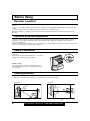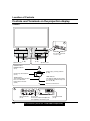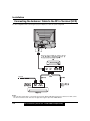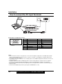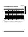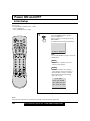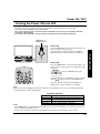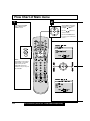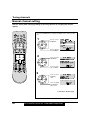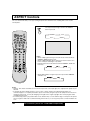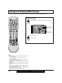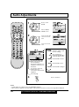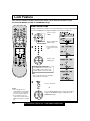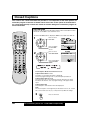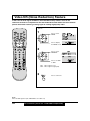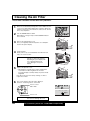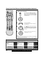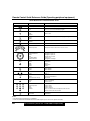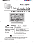
1
Multi-Media Projection Display
Operating Instructions
Models No.
For assistance, please call :
1-888-VIEW PTV(843-9788)
or send e-mail to :
[email protected]
or visit us at www.panasonic.com
(USA)
For assistance, please call :
787-750-4300
or visit us at www.panasonic.com
(Puerto Rico)
PT-40LC12/PT-45LC12
Three Important Reasons to Register Your Product Immediately!
1 Protect Your New Investment...
Register your new projection display for insurance purposes in case
your new projection display is stolen.
2 Product safety notification...
Registering your product can help us to contact you in the unlikely
event a safety notification is required under the Consumer Product
Safety Act.
3 Improved Product Development...
Help us continue to design products that meet your needs.
Register online at www.panasonic.com/register
LSQT0583A
Important Safety Instructions
CAUTION
RISK OF ELECTRIC SHOCK
DO NOT OPEN
WARNING: To reduce the risk of electric shock, do not remove cover or back. No
user-serviceable parts inside. Refer servicing to qualified service personnel.
This symbol warns the user
that uninsulated voltage within
the unit may have sufficient
magnitude to cause electric
shock.
Therefore, it is dangerous to
make any kind of contact with
any inside part of this unit.
This symbol alerts the user that
important literature concerning
the operation and maintenance
of this unit has been included.
Therefore, it should be read
carefully in order to avoid any
problems.
The pictorial representation of
a hot surface within a triangle
is intended to tell the user that
parts inside the product are a
risk of burns to persons.
Note to CATV System Installer: This reminder is provided to call the CATV system installer’s attention to Article
820–40 of the NEC that provides guidelines for proper grounding and, in particular, specifies that the cable ground shall
be connected to the grounding system of the building, as close to the point of cable entry as practical.
Important Safety Instructions For Projection display
1.
2.
3.
4.
Read and apply the operating instructions provided with your projection display.
Read all of the instructions given here and retain them for later use.
Follow all warnings and instructions marked on the projection display.
Unplug this projection display from the wall outlet before cleaning. Do not use liquid or aerosol cleaners. Use a
damp cloth for cleaning.
5. Do not use attachments / accessories not recommended by the projection display manufacturer as they may cause
hazards.
6. Do not use this projection display near water. For example: Avoid placing it near a bathtub, washbowl, kitchen sink,
or laundry tub, in a wet basement, or near a swimming pool, etc.
7. Do not place this projection display on an unstable cart, stand or table. The projection display may fall,
causing serious injury to a child or adult, and serious damage to the appliance. Use only with a cart or
stand recommended by the manufacturer, or sold with the projection display.
7A. An appliance and cart combination shall be moved with care. Quick stops, excessive force, and uneven
surfaces may cause the appliance and cart combination to overturn.
8. Slots and openings in the cabinet and the back are provided for ventilation, to ensure reliable operation of the
projection display and to protect it from overheating. These openings must not be blocked or covered. There shall
be at least 10 cm of space from these openings. The openings shall never be blocked by placing the projection
display on a bed, sofa, rug or other similar surface. This projection display shall never be placed near or over a
radiator or heat register. This projection display shall not be placed in a built-in installation such as a bookcase
unless proper ventilation is provided.
9. Operate only from the type of power source indicated on the marking label. If you are not sure of the type of power
supplied to your home consult your television dealer or local power company.
10. This projection display is equipped with a polarized alternating-current line plug
(a plug having one blade wider than the other). This plug will fit into the power
outlet only one way. This is a safety feature. If you are unable to insert the plug
fully into the outlet, try reversing the plug. If the plug should still fail to fit, contact
your electrician to replace your obsolete outlet. Do not defeat the safety purpose
of the polarized plug.
11. Do not allow anything to rest and to pinch on the power cord. Do not locate this
projection display where the power cord will walked on.
12. Do not overload wall outlets and extension cords as this can result in fire or electric shock.
13. Never push objects of any kind into this projection display through cabinet slots as they may touch dangerous
voltage points or short out parts that could result in a fire or electric shock. Never spill liquid of any kind on the
projection display.
2
For assistance, please call : 1-888-VIEW PTV(843-9788)
Important Safety Instructions
This product has a High Intensity Discharge (HID) lamp that contains a small amount of mercury. It also contains
lead in some components.
Disposal of these materials may be regulated in your community due to environmental considerations.
For disposal or recycling information please contact your local authorities, or the Electronics Industries Alliance:
<http://www.eiae.org.>
Clean the air filter regularly. Not cleaning the air filter could shorten the life of the set.
The lamp has a maximum life of about 5 000 hours.
If use exceeds this figure, the possibility of lamp damage becomes greater.
The lamp should be changed as soon as possible once the lamp warning message appears.
If the lamp is damaged, please contact your nearest dealer.
When VIEWING MODE is set to CINEMA, brightness will be reduced, but the life of the LCD panel can be
prolonged. Therefore, the CINEMA setting is recommended when possible.
3
Getting Started
14. If an outside antenna is connected to the television equipment, be sure the antenna system is grounded so as to
provide some protection against voltage surges and built up static charges. In the U.S.Selection 810 of the National
Electrical Code provides information with respect to proper grounding of the mast and supporting structure,
grounding of the lead-in wire to an antenna discharge unit, size of grounding conductors, location of antennadischarge unit, connection to grounding electrodes, and requirements for the grounding electrode. See Figure.
15. For added protection for this projection display during a lightning storm, or when it is left unattended and unused for
long periods of time, unplug it from the wall outlet and disconnect the antenna. This will prevent damage to the
receiver due to lightning and power-line surges.
16. An outside antenna system shall not be located in the vicinity of overhead power lines or other electric light or
power circuits, or where it can fall into such power lines or circuits. When installing an outside antenna system
extreme care shall be taken to keep from touching such power lines or circuits as contact with them might be fatal.
17. Unplug this projection display from the wall outlet, and refer servicing to qualified service personnel under the
following conditions:
a. When the power cord or plug is damaged or frayed.
b. If liquid has been spilled into the projection display.
c. If the projection display has been exposed to rain or water.
d. If the projection display does not operate normally by following the operating instructions. Adjust only those
controls that are covered by the operating instructions as improper adjustment of other controls may result in
damage and will often require extensive work by a qualified technician to restore the projection display to normal
operation.
e. If the projection display has been dropped or the cabinet has been damaged.
f. When the projection display exhibits a distinct change in performance - this indicates a need for service.
18. Do not attempt to service this projection display yourself as opening or removing covers may expose you to
dangerous voltage or other hazards. Refer all servicing to qualified service personnel.
19. When replacement parts are required, be sure the service technician has used replacement parts specified by the
manufacturer that have the same characteristics as the original part. Unauthorized substitutions may result in fire,
electric shock, or other hazards.
20. Upon completion of any service or repairs to this projection display, ask the service technician to perform routine
safety checks to determine that the projection display is in safe operating condition.
21. WARNING: To prevent fire or shock hazard, do not expose this appliance to rain or moisture.
22. WARNING: Because the temperature of the lamp unit is elevated immediately after its use, directly touching it
may cause burns. After the lamp has cooled enough, replace the lamp unit.
23. CAUTION: To prevent electric shock, match wide blade of plug to wide slot of AC outlet and fully insert. Do not
use this (polarized) plug with a receptacle or other outlet unless the blade can be fully inserted to
prevent blade exposure.
Dear Panasonic Customer
Welcome to the Panasonic family of customers. We hope that you will have many years of enjoyment
from your new projection television set.
To obtain maximum benefit from your set, please read these Instructions before making any adjustments, and
retain them for future reference.
Retain your purchase receipt also, and record the serial number of your set in the space provided on
the rear cover of these instructions.
Visit our Panasonic Web Site for USA : www.panasonic.com
For assistance, please call : 1-888-VIEW PTV(843-9788)
or send e-mail to : [email protected]
or visit us at www.panasonic.com
(USA)
For assistance, please call : 787-750-4300
or visit us at www.panasonic.com
(Puerto Rico)
Trademarks
• Licensed by BBE Sound, Inc. under USP4638258 and 4482866. BBE and BBE symbol are registered trademarks of BBE
Sound, Inc.
• VGA and XGA are trademarks of International Business Machines Corporation.
• Macintosh is a registered trademark of Apple Computer, USA.
• VESA and SVGA are trademarks of the Video Electronics Standard Association.
Even if no special notation has been made of company or product trademarks, these trademarks have been fully respected.
®
®
• Equipped with
-TV Noise Reduction for true MTS reproduction.
-TV Noise Reduction is required for good stereo
®
®
is a registered trademark, and is licensed by
Technology Licensing.
separation and audio fidelity.
FCC STATEMENT:
NOTE: This equipment has been tested and found to comply with the limits for a Class B digital device, pursuant to Part 15 of the
FCC Rules. These limits are designed to provide reasonable protection against harmful interference in a residential
installation. This equipment generates, uses and can radiate radio frequency energy and, if not installed and used in
accordance with the instructions, may cause harmful interference to radio communications. However, there is no guarantee
that interference will not occur in a particular installation. If this equipment does cause harmful interference to radio or
television reception, which can be determined by turning the equipment off and on, the user is encouraged to try to correct
the interference by one or more of the following measures:
• Reorient or relocate the receiving antenna.
• Increase the separation between the equipment and receiver.
• Connect the equipment into an outlet on a circuit different from that to which the receiver is connected.
• Consult the dealer or an experienced radio / TV technician for help.
FCC CAUTION:
To assure continued compliance and prevent undesirable interference, use only the provided shielded VGA cable with 2 ferrite cores
while connecting the Projection display to a computer. Any changes or modifications not expressly approved by the party
responsible for compliance could void the user’s authority to operate this equipment.
Declaration of Conformity
Model Number:
PT-40LC12/PT-45LC12
Trade Name:
Responsible party:
Matsushita Electric Corporation of America.
Address:
One Panasonic Way Secaucus New Jersey 07094
Telephone number:
1-888-VIEW PTV(843-9788)
This device complies with Part 15 of the FCC Rules. Operation is subject to the following two conditions: (1) This
device may not cause harmful interference, and (2) this device must accept any interference received, including
interference that may cause undesired operation.
4
For assistance, please call : 1-888-VIEW PTV(843-9788)
Table of Contents
40
42
44
46
50
52
53
54
55
55
56
57
57
Cleaning the Air Filter ................................................................................................................ 58
Clogged Air Filter Detection .............................................................................................. 59
Air Filter Replacement ...................................................................................................... 59
Replacing the lamp unit ............................................................................................................. 60
Remote Control Quick Reference Guide (Operating peripheral equipment) ........................ 61
Troubleshooting ......................................................................................................................... 68
Specifications ............................................................................................................................. 69
Cleaning ...................................................................................................................................... 70
Customer Services Directory .................................................................................................... 70
Limited Warranty ........................................................................................................................ 71
Index ............................................................................................................................. Back Cover
Information
Other
Information !
Adjusting screen position and size ..........................................................................................
Audio Adjustments ....................................................................................................................
Picture Adjustments ..................................................................................................................
Lock Feature ...............................................................................................................................
Closed Captions .........................................................................................................................
Channel Caption Feature ...........................................................................................................
Weak Signal Display Feature ....................................................................................................
Video NR (Noise Reduction) Feature .......................................................................................
Automatically changing screen size ........................................................................................
Setting when 480p signals (sequential scan) are
input through COMPONENT VIDEO INPUT .............................................................................
RGB Input Feature .....................................................................................................................
Switching languages for display ..............................................................................................
Information .................................................................................................................................
Advanced Operation
Enjoy
more !
20
20
21
22
24
24
26
28
29
29
29
29
29
30
32
33
34
36
38
Basic Operation
Use
Now !
Power ON / OFF ..........................................................................................................................
Initial Setup .......................................................................................................................
Turning the Power ON and OFF .......................................................................................
Flow Chart of Main menu ..........................................................................................................
Tuning channels .........................................................................................................................
Automatic channel setting .................................................................................................
Manual channel setting .....................................................................................................
Projection display operation .....................................................................................................
TV Status display ..............................................................................................................
Using the number keys .....................................................................................................
Using projection display Channel up/down buttons to select input mode .........................
Auto shut off ......................................................................................................................
Invalid operation notice feature .........................................................................................
ASPECT Controls .......................................................................................................................
Searching for the desired channel (Channel search) ..............................................................
Playing peripheral equipment ...................................................................................................
Mute / Freeze / SAP ....................................................................................................................
Split screen .................................................................................................................................
Picture in Picture (PIP) Screen .................................................................................................
Getting Started
TO
Start !
Important Safety Instructions ..................................................................................................... 2
Before Using ................................................................................................................................. 6
Receiver Location ............................................................................................................... 6
Optional External Equipment .............................................................................................. 6
Safety Precaution ............................................................................................................... 6
Viewing position .................................................................................................................. 6
Accessories ........................................................................................................................ 7
Remote Control Battery Installation .................................................................................... 7
Location of Controls .................................................................................................................... 8
Illuminated Remote Control ................................................................................................ 8
Controls and Terminals on the projection display ............................................................. 10
Installation .................................................................................................................................. 12
Connecting the Antenna/Cable to the RF In Terminal (No VCR) ...................................... 12
Connecting the Antenna/Cable to the RF In Terminal (VCR) ............................................ 14
How to connect the “1, 2, 3” Input Terminals .................................................................... 15
How to connect the COMPONENT VIDEO Input Terminals ............................................. 16
How to connect the AV Out Terminals .............................................................................. 17
How to connect the PC Input Terminals ............................................................................ 18
Analog RGB signals that can be input .............................................................................. 19
5
Before Using
Receiver Location
This unit is intended to be used with an optional stand or entertainment center. Consult your dealer for available
options.
Locate for comfortable viewing. Avoid placing where sunlight or other bright light (including reflections) will fall on the
screen.
Use of some types of fluorescent lighting can reduce remote control transmitter range.
Adequate ventilation is essential to prevent internal component failure. Keep away from areas of excessive heat or
moisture.
Optional External Equipment
The Video / Audio connection between components can be made with shielded video and audio cables. For best
performance, video cables should utilize 75 Ω coaxial shielded cables. Cables are available from your dealer or
electronic supply house.
Before you purchase any cables, be sure you know what type of output and input connectors your various components
require. Also determine the length of cable you’ll need.
Safety Precaution
Please take safety precautions to prevent the unit from
falling over.
The unit may fall over during earthquakes, or if someone
stands on or shakes the projection display.
Fixing to a wall
Use a strong rope or a chain (not included) to fasten
the projection display firmly to a strong support such as
a wall or pillar.
Viewing position
To optimize your viewing comfort, please follow the viewing guidelines shown in the diagrams below.
If viewing for an extended period of time, sit as far back from the screen as possible.
<Side view>
<Top view>
70°
30°
30°
70°
1.5 m
6
1.5 m
For assistance, please call : 1-888-VIEW PTV(843-9788)
Before Using
Accessories
Remote Control
(EUR7603Z80)
Batteries 2 “AA”
RGB Cable (2 m) (LSJA0239-1 or LSJA0443)
Accessory Air Filter (LSYC0239)
Getting Started
(1)
(2)
(3)
(4)
Remote Control Battery Installation
Requires two AA batteries (supplied).
1.Turn the Transmitter face down.
Remove top cover by pressing
down on marking and sliding cover
off in the direction indicated.
2.Install the batteries as shown in the
battery compartment.
(Polarity + or – must match the
markings in the compartment).
3.Replace the cover and slide in
reverse until the lock snaps.
Two AA size
Helpful Hint:
For frequent remote control users, replace old batteries with Alkaline batteries for longer life.
Precaution on battery use
Incorrect installation can cause battery leakage and corrosion that will damage the remote control transmitter.
Observe the following precautions:
1. Batteries should always be replaced as a pair. Always use new batteries when replacing the old set.
2. Do not mix battery types (example: “Zinc Carbon” with “Alkaline”).
3. Do not attempt to charge, short-circuit, disassemble, heat or burn used batteries.
4. Battery replacement is necessary when the remote control acts sporadically or stops operating the projection display
set.
Helpful Hint:
Whenever you remove the batteries, you may need to reset the remote control infrared codes. We recommend
that you record the code on page 62, prior to setting up the remote.
7
Location of Controls
Illuminated Remote Control
POWER button
Press to turn the projection display ON or OFF. (P. 21)
MUTE button
Press this button to mute the sound. (P. 34)
Mode Selection buttons
Selects the operation mode for the remote control. (PP. 61-67)
DVD (Digital Versatile Disc) Mode Selection for
Remote Control
Aux Mode Selection for
Remote Control
VCR Mode Selection for
Remote Control
Receiver / Amplifier Mode Selection for
Remote Control
TV Mode Selection for
Remote Control
Digital Broadcasting Satellite for
Remote Control
Digital TV Mode Selection for
Remote Control
Cable TV Mode Selection for
Remote Control
Number keys
When 6 is pressed, channel 6 is displayed in single screen. (P. 29)
R-TUNE button
Press to view previous channel or video mode.
Function buttons
PIP Move
8
PIP ON/OFF
(P. 39)
(P. 38)
SPLIT Function/
PIP SIZE
(PP. 36, 39)
FREEZE
PIP/SPLIT SWAP
(P. 34)
(PP. 37, 39)
CH Search
PIP/SPLIT
CH Down
PIP/SPLIT
CH Up
BBE sound
ON/OFF
(P. 32)
(PP. 37, 39)
(PP. 37, 39)
(P. 43)
For assistance, please call : 1-888-VIEW PTV(843-9788)
Location of Controls
ASPECT button
Changes the screen size. (P. 30)
Getting Started
TV/VIDEO button
This input mode changes each time this button is pressed. (P. 33)
SAP button
Changes the audio mode. (P. 35)
Light button
Lights all buttons. The selected mode button (TV, VCR, etc.) flashes.
Changes to the next channel up
Increase
volume
Reduces
volume
Display menu
Press the ACTION
button to display
Changes to the
Menu screen
next channel
down
The screen below
is displayed for 5
seconds.
(P. 29)
NORMA L
S T E R EO
SAP
MONO
CH 1 2
ABC
When the Menu screen is displayed, (PP. 22, 23)
Moves cursor upward
during menu mode.
Moves
cursor to the
left during
menu mode.
Moves cursor to the
right during menu
mode.
Sets the items.
Moves cursor
downward during
menu mode.
Returns to normal
viewing from the
MENU screen.
Previous before
item in MENU.
Note:
This section describes TV mode only. For other modes, see pages 61-67.
9
Location of Controls
Controls and Terminals on the projection display
< FRONT >
A
Open
Press the mark on
the center of the front
cover to open.
Lamp unit
(P. 60)
Speaker cover
Air filter
(P. 58)
Speaker cover
POWER button/
POWER indicator
(P. 21)
Channel up / down buttons
(P. 29)
TEMP indicator
This indicator lights up when
there is an abnormal
temperature in the unit.
(P. 68)
Volume up(+) / down(–) buttons
(P. 28)
LAMP indicator
This indicator lights up when there
is a malfunction with the lamp unit.
(PP. 21, 60, 68)
Remote Control Sensor
A
Input 3 terminals
(P. 15)
10
Phones jack
Connect an earphone/headphones
(not supplied) to the Phones jack.
PC Input terminal
(P. 18)
For assistance, please call : 1-888-VIEW PTV(843-9788)
Location of Controls
< REAR >
Getting Started
AV out terminals
(P. 17)
Input 2 terminals
(P. 15)
Input 1 terminals
(P. 15)
Vent
Component signal input terminals
(P. 16)
VHF/UHF terminal
(PP. 12-14)
Note:
Make sure the vent is not clogged. (This could cause damage.)
11
Installation
Notes on connections
• Turn off the power supply for all components before making any connections.
• If the cables necessary for connecting a component to the system are not included with the component or available
as an option, you may need to fashion a cable to suit the component concerned.
• Read the instruction manual for each system component carefully before connecting it.
• If there is a lot of jitter in the video signal input from the video source, the picture on the screen may flicker. In this
case, it will be necessary to connect a TBC (time base corrector).
Connecting the Antenna / Cable to the RF in Terminal (No VCR)
Antenna Connection
For proper reception of VHF / UHF channels, an external antenna is required. For best reception an outdoor
antenna is recommended.
VHF Antenna
UHF Antenna
Mixer
RF
Coaxial Cable
VHF/UHF TERMINAL
ON THE BACK OF THE
PROJECTION DISPLAY
WARNING
When using “Nut type” RF coaxial cables, tighten with fingers only. Overtightening may damage terminals.
12
For assistance, please call : 1-888-VIEW PTV(843-9788)
Installation
Cable Connection
Use this configuration when connecting the projection display to a cable TV system.
Getting Started
CABLE BOX
TERMINAL ON
INPUT
OUTPUT
THE BACK OF
THE CABLE BOX
Or
In from cable
Connect the cable from the antenna
or cable system to the VHF/UHF
terminal on the back of the
Projection display.
.
In from cable
Notes:
• Certain cable systems offset some channels to reduce interference or have Premium (scrambled) channels. A cable
converter box is required for proper reception. Check with your local Cable company for its compatibility requirements.
• For reception of cable channels (01 - 125) connect the cable supplied by your local cable company.
Antenna Mode must be set to CABLE. (P. 24)
13
Installation
Connecting the Antenna / Cable to the RF in Terminal (VCR)
Use this configuration when connecting the projection display to a cable TV system using VCR.
Connect the cable from the Output terminal on the back
o f t h e C a b l e B o x o r antenna/c a b l e s y s t e m t o t h e
Antenna input terminal on the back of the VCR.
VCR
OUTPUT INPUT
OUTPUT
S-VIDEO
VIDEO
L-AUDIO-R
Or
In from cable
TO VCR
TERMINAL ON
Incoming Cable from
THE BACK OF
THE CABLE BOX
TO VCR
Antenna or Cable TV
INPUT
OUTPUT
System
CABLE BOX
Notes:
• When the RF coaxial cable is connected to the projection display VHF/UHF terminal via a cable box or VCR, set the
TV channel to CH3 or CH4. This does not apply when signal is input from VIDEO INPUT.
14
For assistance, please call : 1-888-VIEW PTV(843-9788)
Installation
How to connect the “1, 2, 3” Input Terminals
Getting Started
Connects VCRs and other peripheral equipment
(S-VHS VCR)
Audio
R
OUT
L
Video
S-Video
OUT
OUT
S-VIDEO
AUDIO
Similar connections are available at the INPUT 1, 2, 3 input terminals.
(VHS VCR)
Audio
R
OUT
Video
L
OUT
VIDEO
AUDIO
Similar connections are available at the INPUT 1, 2, 3 input terminals.
Notes:
• Similar connections are available at the INPUT 1, 2, 3 input terminals.
• Input 3 is located on the front of the unit.
• Select the desired VIDEO input position by pressing the TV/VIDEO button. (P. 33)
• When connecting video cables, priority is given to the S-Video cable when the S-Video input terminal and the video
input terminal are connected at the same time.
15
Installation
How to connect the COMPONENT VIDEO Input Terminals
Because each Y, PB, and PR signal is input independently, the Component signal allows for more accurate color
reproduction.
The Component signal output terminal indication will differ according to the output device (Y, PB / Cb, PR / Cr). Please
read the operating instructions included with the output device.
DVD Player
Audio
R
OUT
DVD(Y/PB/PR) OUT
L
PR
PB
Y
COMPONENT VIDEO
AUDIO
Notes:
• Similar connections are available at the COMPONENT VIDEO INPUT 1, 2 Terminals.
• Select the desired COMPONENT VIDEO INPUT position by pressing the TV/VIDEO button. (P. 33)
• Component video signals that can be input are 480i, 480p, 720p, and 1080i.
16
For assistance, please call : 1-888-VIEW PTV(843-9788)
Installation
How to connect the AV Out Terminals
Recording Equipment
(VHS VCR)
Audio
R
IN
L
Video
S-Video
IN
IN
S-VIDEO
Or
VIDEO
AUDIO
Stereo System
(A Stereo Amplifier and Speakers)
AUDIO
Notes:
• Never connect the VIDEO IN and OUT terminals to the same video recorder, as this could cause incorrect operation.
• Even if TV is in Split or PIP mode, OUT terminals only output the main picture and sound signals. A sub-picture,
including channel search, etc., will not be output.
• VIDEO OUT terminals will not output Y, PB, PR, or RGB signals.
• The S-Video OUT terminal outputs the same signal that is input from the S-Video IN terminal.
17
Getting Started
The “AV Out” Terminals output the same signals as the main picture on the projection display screen and sound from
the speaker at that time, e.g. TV programs or signals from INPUT 1, 2, 3 terminals.
Installation
How to connect the PC Input Terminals
COMPUTER
PC audio cable (M3 stereo mini pin)
Connect a cable which matches
the audio output terminal on the computer.
Conversion adapter (If necessary)
RGB cable (D-SUB 15P)
Signal Names for D-SUB 15P Connector
5
10 9
4
3
8
2
7
1
6
15 14 13 12 11
Pin Layout for PC Input
Terminal
Pin No.
1
2
3
4
5
6
7
8
Signal name
R
G
B
NC
NC
Ground for R
Ground for G
Ground for B
Pin No.
9
10
11
12
13
14
15
Signal name
NC
Ground
NC
NC
HD/CSYNC
VD
NC
NC: Not connected
Notes:
• Some PC models cannot be connected to the set. A conversion adapter is required to use the RGB cable (D-SUB
15P) to connect a Macintosh computer to the set. There is no need to use an adapter for computers with PC / AT
compatible D-SUB 15P terminal.
• The computer shown in the illustration is for example purposes only. Additional equipment and cables shown are not
supplied with this set.
• The picture will become dark if an RGB signal with a vertical scanning frequency of 62 Hz is input. To obtain the
optimum picture quality with the projection display, a vertical scanning frequency of 60 Hz is recommended.
• Do not set the horizontal and vertical scanning frequencies for PC signals which are above or below the specified
frequency range.
• Select the desired RGB input position by pressing the TV/VIDEO button. (P. 33)
18
For assistance, please call : 1-888-VIEW PTV(843-9788)
Installation
Analog RGB signals that can be input
DTV Format
Signals
Personal Computer Signals
Mode type
VGA400 (70 Hz)
VGA480 (60 Hz)
Macintosh 13˝
VESA400 (85 Hz)
VESA480 (72 Hz)
VESA480 (75 Hz)
VESA480 (85 Hz)
SVGA (56 Hz)
SVGA (60 Hz)
SVGA (72 Hz)
SVGA (75 Hz)
SVGA (85 Hz)
Macintosh 16″
* XGA (60 Hz)
* XGA (70 Hz)
* XGA (75 Hz)
* Macintosh 19″
* XGA (85 Hz)
480 i
480 p
720 p
*1080 i
No. of dots
(H x V)
640 X 400
640 X 480
640 X 480
640 X 400
640 X 480
640 X 480
640 X 480
800 X 600
800 X 600
800 X 600
800 X 600
800 X 600
832 X 624
1 024 X 768
1 024 X 768
1 024 X 768
1 024 X 768
1 024 X 768
664 X 485
720 X 483
1 280 X 720
1 920 X 1 080
Signal data
Horizontal frequency
(kHz)
31.47
31.47
35.00
37.86
37.86
37.50
43.27
35.16
37.88
48.08
46.88
53.67
49.73
48.36
56.48
60.02
60.24
68.68
15.73
31.47
45.00
33.75
Vertical frequency
(Hz)
70.08
59.94
66.67
85.08
72.81
75.00
85.01
56.25
60.32
72.19
75.00
85.06
74.55
60.00
70.07
75.03
74.93
85.00
29.97
59.94
60.00
30.00
Information menu
display
VGA400 70Hz
VGA 60Hz
MAC 13
VESA 85Hz
VGA 72Hz
VGA 75Hz
VGA 85Hz
SVGA 56Hz
SVGA 60Hz
SVGA 72Hz
SVGA 75Hz
SVGA 85Hz
MAC 16
XGA 60Hz
XGA 70Hz
XGA 75Hz
MAC 19
XGA 85Hz
480 i
480 p
720 p
1080 i
Notes:
• Input signals, other than those listed with a mark, will give you a beautiful, stable picture.
• The front D-SUB15P connector can accept *
RGB(H-V sync separate) and RGB(sync on green). However, it is
not guaranteed to display stable color when using RGB(sync on green).
• When used with an external video processor/scaler, it must have RGB(H-V sync separate) output.
19
Getting Started
The table below lists the different types of analog RGB signals that can be input.
If a signal which differs greatly from any of the types listed below is input, the picture image may not be displayed
correctly, or a black background may be displayed. At this time, “signal” will flash in the on-screen display for about 5
seconds.
Power ON and OFF
Initial Setup
First, check the connection of the Plug to the Wall Outlet and the Antenna/Cable to the RF in Terminal.
(PP. 12-14.)
If using Cable Box, DSS Receiver, or VCR,
• Turn on Cable Box.
• Turn off DSS Receiver, or VCR.
1
Press the POWER button to turn the
projection display on.
(Refer to page 21 for “Turning the Power
ON and OFF”.)
Automatic Channel Setting is performed.
CH AU TO S E T PROCE ED I NG
Note:
To cancel AUTO SET in progress, press the
SWAP button.
Case 1
When setup is complete, the lowest
channel picture appears.
Case 2
If setup is incomplete, the following
screen appears. Check connection of
Antenna/Cable to the RF in Terminal,
then try Automatic Channel Setting
again. (PP. 24, 25)
NO CH FOUND
P L E A S E CH E CK AN T E NNA
CAB L E CONNEC T I ON T HEN
PRE S S AC T I ON KE Y AGA I N
Note:
When the unit is turned on for the first time, Automatic Channel Setting is performed.
20
For assistance, please call : 1-888-VIEW PTV(843-9788)
Power ON / OFF
Turning the Power ON and OFF
Always be sure to follow the procedure given below to turn the projection display power ON and OFF.
• The lamp cooling fan will continue to operate for approximately 1 minute after the power is turned off.
At the same time, the POWER indicator will blink Red.
Do not disconnect the power cord from the power outlet and do not open any circuit breakers while the
cooling fan is still operating.
Do not disconnect the power cord from the power outlet while the power indicator blinks Red.
POWER button/
POWER indicator
Power ON
Press the POWER button on the projection display or the
remote control to turn the power on.
The Power Indicator will become Green and blink for
approximately 10 seconds, and then turn solid Green.
Press the POWER button on the projection display or the
remote control to turn the power off. Confirming message
will appear.
POWER OFF
Press the POWER button again.
YES
NO
If the POWER button is accidentally pressed, select NO
with the ,
buttons, then press the ACTION button.
The Power Indicator will become Red and blink for
approximately 1 minute, and then turn solid Red.
Note:
When the AC Cord is unplugged, the internal cooling fan stops operating. In this case, the lamp will be insufficiently
cooled and will take a while to turn ON again.
The Power Indicator
LED
Red
Red blink
Green
Green blink
ACTION
Power – OFF (Standby mode)
Power – OFF (Now cooling)
Power – ON
Power – ON (Preparing to light lamp)
Notes:
• If the POWER button is accidentally turned off during use, after power is turned back on, it may take a short period
before the lamp automatically comes on.
• After the unit is turned on, maximum picture brightness will be achieved in 5-10 minutes. This is normal.
21
Basic Operation
Power OFF
Flow Chart of Main menu
2
1
Select MENU desired by
pushing Left “ ” button
or Right “ ” button.
Pressing the ACTION
button displays the
MENU screen.
Use the , buttons to
select an item.
Use the ACTION button
to set or go to next menu
screen.
AD J U S T
SE T
L
PA
IN
CG
TUA
RG
EE
UP
: E NG L I S H
AH
UA
DN
IN
OE L
C
POC
SK
I T I ON / S I Z E
L
IA
NP
FT
OR
MN
A T I ON
C
IO
V I D EO
PAGE
SELECT
END
RECALL
Note:
Depending on the signal
being input, some items
may or may not be
adjustable and some
functions may or may not
be available.
AD J U S T
SE T
L
PA
IN
CG
TUA
RG
EE
UP
: E NG L I S H
AH
UA
DN
IN
OE L
C
POC
SK
I T I ON / S I Z E
L
IA
NP
FT
OR
MN
A T I ON
C
IO
V I D EO
PAGE
22
For assistance, please call : 1-888-VIEW PTV(843-9788)
SELECT
END
RECALL
Flow Chart of Main menu
Adjust items
Returning to the previous screen
If you press the RECALL button while a
menu screen is being displayed, the display
will return to the previous screen.
Set an item
Select an item
TO PICTURE
ADJUST menu
TO AUDIO
ADJUST menu
P I C T UR E
V I EW I NG MOD E
: NORMA L
SELECT
EXIT
PP. 44, 45
TO LANGUAGE
selection screen
I NPU T S I GNA L
V POS I T I ON
S P E AK E R
: ON
H W I DTH
S URROUND
: OF F
NORMA L
SELECT
EXIT
ADJUST
RECALL
PP. 42, 43
: NARRO W
SELECT
EXIT
RECALL
RECALL
PP. 40, 41
TO CHANNEL
menu
AN T E NNA
:
AH
UA
DN
IN
OE L
C
AU T O S E T
TO LOCK
selection screen
CAB L E
L OCK
EN T ER
MANUA L
CHANN E L CA P T I ON
SE T
V I D EO
WE AK S I GNA L D I S P L A Y : OFF
EN T ER
SELECT
END
SELECT
EXIT
RECALL
P. 57
RECALL
PP. 24-27, 52, 53
TO CAPTION
menu
4 - D I G I T COD E
- - - -
POC
SK
I T I ON / S I Z E
L
IA
NP
FT
OR
MN
A T I ON
C
IO
PAGE
EXIT
P. 57
S E T U P CHANN E L
UP
: E NG L I S H
480 i
H POS I T I ON
: NORMA L
AUD I O AD J U S T
RECALL
L
PA
IN
CG
TUA
RG
EE
AUD I O ME NU
INFORMATION
screen
Basic Operation
: NORMA L
P I C T UR E AD J U S T
SE T
POS I T I ON
AUD I O
P I C T UR E ME NU
AD J U S T
TO POSITION/SIZE
ADJUST menu
:0-9
RECALL
EXIT
PP. 46-49
TO VIDEO
menu
CAP T I ON
V I D EO
CAP T I ON MODE : OF F
CC ON MU T E
: CA P C 1
V I D EO NR
: OF F
ID- 1
: OF F
4 8 0 P CO L OR MA T R I X : S D T V
RGB
SELECT
EXIT
RECALL
PP. 50, 51
: VGA
SELECT
EXIT
RECALL
P. 54-56
23
Tuning channels
Automatic channel setting
Automatically searches and adds receivable channels to memory.
Press the ACTION button to display the MENU screen and select SET
UP.
1
Press to select
CHANNEL.
AD J U S T
SE T
L
PA
IN
CG
TUA
RG
EE
UP
: E NG L I S H
AH
UA
DN
IN
OE L
C
POC
SK
I T I ON / S I Z E
L
IA
NP
FT
OR
MN
A T I ON
C
IO
V I D EO
PAGE
Press to display
the CHANNEL.
2
Press to select
ANTENNA.
SELECT
END
RECALL
S E T U P CHANN E L
AN T E NNA
:
CAB L E
AU T O S E T
MANUA L
SE T
CHANN E L CA P T I ON
WE AK S I GNA L D I S P L A Y : OFF
SELECT
EXIT
RECALL
Press to select
TV or CABLE.
3
Press to select
AUTO SET.
S E T U P CHANN E L
AN T E NNA
:
CAB L E
AU T O S E T
MANUA L
SE T
CHANN E L CA P T I ON
WE AK S I GNA L D I S P L A Y : OFF
SELECT
EXIT
RECALL
Press to run
AUTO SET.
Note:
To cancel AUTO SET in progress,
press the SWAP button.
CH AU TO S E T PROCE ED I NG
Channels will automatically advance until all channels have been
scanned. Channel numbers with a video signal present will be
stored in the channel scan memory.
Continued on the next page.
Note:
TV or Cable Tuning mode must be set according to your connections.
24
For assistance, please call : 1-888-VIEW PTV(843-9788)
Tuning channels
4
Case 1
When setup is complete, the lowest channel picture
appears.
Case 2
If setup is incomplete, the screen at right appears. Check
connection of Antenna/Cable to the RF in Terminal, then try
Automatic Channel Setting again.
5
NO CH FOUND
P L E A S E CH E CK AN T E NNA
CAB L E CONNEC T I ON T HEN
PRE S S AC T I ON KE Y AGA I N
Press to exit menu.
Basic Operation
Notes:
• After AUTO SET is finished, the lowest channel number added will be received.
• Some channels with very weak signals may be locked into memory. It desired, these channels can be deleted
manually using the MANUAL SET feature.
25
Tuning channels
Manual channel setting
Use this setting when changing setting of receiving channels or changing the channel
display.
Press the ACTION button to display the MENU screen and select SET
UP.
1
Press to select
CHANNEL.
AD J U S T
SE T
L
PA
IN
CG
TUA
RG
EE
UP
: E NG L I S H
AH
UA
DN
IN
OE L
C
POC
SK
I T I ON / S I Z E
L
IA
NP
FT
OR
MN
A T I ON
C
IO
V I D EO
PAGE
SELECT
END
RECALL
Press to display
the CHANNEL.
2
Press to select
ANTENNA.
S E T U P CHANN E L
AN T E NNA
:
CAB L E
AU T O S E T
MANUA L
SE T
CHANN E L CA P T I ON
WE AK S I GNA L D I S P L A Y : OFF
SELECT
EXIT
RECALL
Press to select
TV or CABLE.
3
Press to select
MANUAL
SET.
S E T U P CHANN E L
AN T E NNA
:
CAB L E
AU T O S E T
MANUA L
SE T
CHANN E L CA P T I ON
WE AK S I GNA L D I S P L A Y : OFF
Press to display
the MANUAL
SET screen.
SELECT
EXIT
RECALL
Continued on the next page.
26
For assistance, please call : 1-888-VIEW PTV(843-9788)
Tuning channels
4
To add channel
MANUA L
Press to select channel.
EN T ER
SE T
CHANN E L
CHOOS E
U S I NG
:
01
A
CHANN E L
CH
U P / DOWN
ADD
EXIT
RECALL
Press to add channels to memory.
Basic Operation
To delete channel
MANUA L
Press to select channel.
EN T ER
SE T
CHANN E L
CHOOS E
U S I NG
:
01
A
CHANN E L
CH
U P / DOWN
DELETE
RECALL
EXIT
Press to delete channels from memory.
5
Repeat steps 4 to continue adding or deleting channels.
6
Press to exit menu.
Note:
Some channels with very weak signals may be locked into memory. It desired, these channels can be deleted manually
using the MANUAL SET feature.
27
Projection display operation
Operation can be done from the projection
display.
POWER button/
POWER indicator
Channel up / down buttons
Volume up(+) / down(–) buttons
Remote Control Sensor
1
Press to operate the projection
display with the remote control.
2
Press to turn the projection display on.
3
CABLE TV
Press to select
the desired
channel. (or use
number keys )
125 or 69
CH01
CH02
Or
CH125
Note:
Refer to “Using
the number keys”
on the next page.
4
Press to
select the
desired
volume
level.
CH03
26
Notes:
• The channel number and volume level are stored even after the projection display is turned off.
• Power consumption can be reduced if the volume level is lowered.
28
For assistance, please call : 1-888-VIEW PTV(843-9788)
Projection display operation
TV status display
Press the RECALL button, except when the MENU screen is displayed, to display current
TV status information.
Aspect types
(P. 30)
Receivable
broadcast types
(P. 35)
NORMA L
S T E R EO
SAP
MONO
CH 1 2
ABC
Channel
Channel caption
(P. 52)
Using the number keys
Example 1: To select channel 125, first press the 1 key, then 2, then 5.
Example 2: To select channel 12, press the 1 key, then 2. Channel 12 appears momentarily.
Example 3: To select channel 8, press the 8 key. Channel 8 appears momentarily.
Using projection display Channel up/down buttons to select input mode
CABLE TV
Projection display Channel up/down
buttons can also be used to select an
outside input as shown right.
125 or 69
CH01
RGB
CH125
* No input mode is displayed for terminals with
no equipment connected.
LINE 1
*
*
COMPONENT 2
LINE 2
*
*
COMPONENT 1
LINE 3
*
Auto shut off
To extend lamp life, if there is no signal to the set’s tuner for 5 minutes, the lamp will shut off automatically.
Invalid operation notice feature
If an invalid operation is attempted, the mark shown right is
displayed.
FREEZE
29
Basic Operation
When selecting CABLE channels 100 to 125 with the number keys, first press the 1 key,
and then enter the remaining two digits.
ASPECT Controls
The color monitor will allow you to enjoy viewing the picture at its maximum size, including wide screen cinema
format picture.
The aspect mode changes each time the ASPECT
button is pressed.
NORMAL
JUST
FULL
ZOOM
FULL
Notes:
• When a 480p signal is being received, the mode switches between
NORMAL, ZOOM, and FULL only.
• When a 1080i and 720p signal is being received, the mode is set to
FULL, and aspect switching is not possible.
• During PC input, the mode switches between NORMAL, TRUE and
FULL only.
NORMAL
FULL
TRUE
• When XGA and Mac 19 signal is input, the aspect will be NORMAL
and FULL only.
NORMAL
FULL
Notes:
• However, if the mode selected does not match the aspect ratio of the input signal, the original picture quality may be
affected.
• If using this Projection display in places, such as cafes or hotels, with the aim of displaying programs for a
commercial purpose or for public presentation, please note that by using the aspect ratio (16:9) selection function to
change the aspect ratio, you may be infringing on the rights of the original copyright owner of that program under
copyright protection laws.
• If a normal (4:3) picture is projected in wide screen, distortion may occur around the edges so that part of the picture
may no longer be visible. We recommend viewing in 4:3 mode so you can enjoy the picture as it was intended to be
seen.
30
For assistance, please call : 1-888-VIEW PTV(843-9788)
ASPECT Controls
Mode
Picture
NORMAL
Explanation
4
3
NORMAL
JUST
16
JUST
ZOOM mode magnifies the central section of the
picture.
9
FULL will display the picture at its maximum
size but with sight elongation.
3
You can reduce the image and adjust it to the
original image quality. (Except XGA)
16
FULL
TRUE
9
16
ZOOM
FULL
9
JUST mode will display a 4:3 picture at maximum size but with aspect correction applied to
the center of the screen so that elongation is
only apparent at the left and right edges of the
screen. The size of the picture will depend on the
original signal.
4
TRUE
Notes:
• The screen size changes if ID-1 is detected. (P. 55)
31
Basic Operation
ZOOM
NORMAL will display a 4:3 picture at its standard
4:3 size.
Searching for the desired channel (Channel search)
Channel search displays each channel, in order, as a paused image. Channels are displayed
from the left top to the right bottom in order. When it reaches the right bottom, the next
channel is displayed at the left top, overwriting the previously displayed channel.
When the SEARCH/REC button is pressed during
single screen.
CH03
CH03
02
05
06
07
08
10
Or
RGB
02
05
06
07
08
10
(PC input)
When a channel button is pressed during
channel search.
• Number keys:
Example: When 6 is pressed, channel 6 is displayed in single
screen.
• Channel up and down buttons:
When or button is pressed, the next channel up or down is
displayed in single screen.
Ex. Select channel 6
Sound from the left screen is
output from the speakers on the
projection display set.
Notes:
• To end channel search, press SEARCH/REC.
• While using the PIP feature, Channel search is not available.
32
For assistance, please call : 1-888-VIEW PTV(843-9788)
CH06
Playing peripheral equipment
Confirming connections
A video camera uses the Input 3 terminal on the front of the projection display.
Example:
VCR
Connect Input 3
Video camera
DVD player
To S-video output
or video output
This equipment can also be
connected to the rear terminals.
See Connections for details.
To audio output
Basic Operation
Turning the power on and switching input modes
1
Turn the projection
display on.
2
The input mode
changes each time
this button is pressed.
TV
LINE 1
*
RGB
*
* No input mode is
displayed for terminals
with no equipment
connected.
LINE 2
*
COMPONENT 2
*
COMPONENT 1
LINE 3
*
LINE 1:
Signal of source connected to INPUT 1 is displayed.
LINE 2:
Signal of source connected to INPUT 2 is displayed.
LINE 3:
Signal of source connected to INPUT 3 is displayed.
COMPONENT 1:
Signal of source connected to COMPONENT VIDEO INPUT 1 is displayed.
COMPONENT 2:
Signal of source connected to COMPONENT VIDEO INPUT 2 is displayed.
RGB:
Signal of source connected to PC IN is displayed.
3
Operate the connected equipment.
33
Mute / Freeze / SAP
Sound mute
Useful when answering the phone or receiving
unexpected visitors
Press this button to mute the sound. Press again to
reactivate sound. Sound is also reactivated when power
is turned off or volume level is changed.
MU T E
Note:
The audio output from AV OUT is not muted.
Freezing pictures
Projection can be switched between a frozen (still)
picture and a moving picture each time the FREEZE
button on the remote control unit is pressed. Press
FREEZE button again to resume motion.
F RE E Z E
Note:
The video output from AV OUT is not frozen.
34
For assistance, please call : 1-888-VIEW PTV(843-9788)
Mute / Freeze / SAP
Receivable Broadcast Types
The following are possible broadcast types with their accompanying on-screen displays. The signal being
received is indicated with a “ ” mark while the selected audio mode is indicated with an arrow. To change the
audio mode for these broadcasts, follow the “Select Audio Mode for TV Viewing” section (below.)
CH 1 2
MTS Stereo and SAP broadcast
Multi-channel Television Sound Stereo (main language) and Secondary
Audio Program (sub language) broadcasts are both being received
simultaneously.
Select the STEREO or SAP audio mode.
S T E R EO
SAP
MONO
CH 1 2
MTS Stereo broadcast
Multi-channel Television Sound Stereo broadcast. Select STEREO
audio mode.
• If stereo broadcast is weak and the display flickers, select MONO
audio mode for possibly better results.
S T E R EO
SAP
MONO
Basic Operation
CH 1 2
SAP broadcast
Secondary Audio Program (sub language.)
Select SAP audio mode for the sub language.
S T E R EO
SAP
MONO
CH 1 2
MONO broadcast
Normal monaural sound broadcast.
S T E R EO
SAP
MONO
Select Audio Mode for TV Viewing
Press SAP button to select the desired audio mode as described below.
(Arrow shows selection.)
• Each press of SAP button will change the audio mode as shown below.
• “SAP” is selected with first press of SAP button.
< Example >
Press
SAP
CH 1 2
S T E R EO
SAP
MONO
CH 1 2
S T E R EO
SAP
MONO
CH 1 2
S T E R EO
SAP
MONO
Press
SAP
Press
SAP
35
Split screen
Splitting the screen
Press to split.
(The previously selected screen appears on the left.)
CH03
CH05
Left screen
(Main picture)
Right screen
(Sub picture)
• Returning to one screen.
Press to return.
Selecting the screen mode for split screen.
Press to
select
modes.
CH03
CH05
SPLIT SCREEN FULL
CH03
Notes:
• Sound from the Left screen is output from
the speakers on the projection display set.
• When the screen is split, signals of the Left
screen are output from the rear monitor
output terminal.
• The left and right screens are processed by
individual circuits and, therefore, may
slightly vary in image quality.
• Split screen returns to single screen when
the projection display is turned off.
• With the Left screen, as with a single
screen, you can change the input, change
channels, and adjust the volume.
• The right and left screens cannot display
the same picture at the same time.
• A split screen which includes an RGB signal
from a PC is fixed as SPLIT SCREEN
NORMAL (PC input).
36
CH05
SPLIT SCREEN NORMAL
RGB
SPLIT SCREEN NORMAL
(PC input)
For assistance, please call : 1-888-VIEW PTV(843-9788)
CH05
Split screen
Changing the channel of the right screen
1
Press to select the desired
channel.
Example:
During SPLIT SCREEN NORMAL.
CH03
Press to swap.
Example:
During SPLIT SCREEN NORMAL.
CH05
CH03
Swapping left and right screens
CH03
CH05
CH05
CH03
CH06
Basic Operation
Example:
During SPLIT SCREEN NORMAL
(PC input)
PIP , buttons can also be used to select an
outside input for the right side of the screen.
RGB
CABLE TV
125 or 69
CH05
CH01
RGB
CH125
* No input mode
is displayed for
terminals with
no equipment
connected.
LINE 1
LINE 2
LINE 3
*
*
COMPONENT 2
*
COMPONENT 1
*
*
Note:
When outside input is finished, the lowest registered channel number is displayed. For faster
selection, press the SWAP button to change the
screen to the left. Then, press the TV/VIDEO button
to directly change the input. Finally, press SWAP
button again to change the screen back to the right.
CH05
RGB
Note:
Picture quality may change according to the
combination of signals input to the left and right
screens.
37
Picture in Picture (PIP) Screen
You can view two pictures simultaneously using two tuners and picture in picture (PIP) display function.
Display PIP screen
Press to split
(The previously selected screen appears on the Main.)
CH03
PIP CH05
Main screen
(Main picture)
PIP screen
(Sub picture)
• Returning to one screen.
Press to return.
Notes:
• Sound from the Main screen is output from the speakers on the
projection display set.
• In PIP mode, the Main screen signal is output from the rear
monitor output terminal.
• Because Main and PIP screens are processed by individual
circuits, image quality may vary slightly.
• PIP mode returns to single screen when the projection display is
turned off.
• The Main and PIP screens cannot display the same picture at
the same time.
• An RGB signal cannot be displayed on a PIP screen or a Main
screen.
• A component signal cannot be displayed on a PIP screen. Thus,
when a component signal is displayed on the Main screen, the
SWAP button becomes invalid.
• With the Main screen, as with a single screen, you can change
the input, change channels, and adjust the volume.
38
For assistance, please call : 1-888-VIEW PTV(843-9788)
Picture in Picture (PIP) Screen
Changing the channel of the PIP screen
Swapping Main and PIP screens
Press to select the desired channel.
Press to swap.
Example:
During Main screen NORMAL.
Example:
During Main screen NORMAL.
CH03
PIP CH05
PIP CH05
CH03
CH05
PIP CH06
PIP CH03
Basic Operation
CH03
Note:
PIP , buttons can also be used to select an outside input for
the PIP screen.
Move PIP screen
You can move the PIP screen to four positions.
Selecting the screen size for PIP screen
You can choose PIP screen size of 3 magnifications.
Press repeatedly
to select PIP
position.
Press repeatedly
to select PIP
screen size.
CH03
1
2
Initial size
Note:
The last size chosen is saved and will not be erased
even if the power is turned off.
2
1
CH03
3
Initial position
Note:
The last position chosen is saved and will not be
erased even if the power is turned off.
39
Adjusting screen position and size
1
2
Press to select the screen mode.
Press the ACTION button to display the MENU screen and select
ADJUST.
Press to select
POSITION/SIZE.
AD J U S T
SE T
UP
L
PA
IN
CG
TUA
RG
EE
: E NG L I S H
AH
UA
DN
IN
OE L
C
POC
SK
I T I ON / S I Z E
L
IA
NP
FT
OR
MN
A T I ON
C
IO
V I D EO
Press to display
POSITION/SIZE.
3
Press to
select the
menu to set
each item.
PAGE
SELECT
END
RECALL
POS I T I ON
H POS I T I ON
V POS I T I ON
H W I DTH
: S HR I NK
NORMA L
Press to adjust
POSITION/SIZE.
ADJUST
JUST mode
NORMAL is displayed at default.
POS I T I ON
H POS I T I ON
V POS I T I ON
H W I DTH
: W I DEN
NORMA L
ADJUST
SELECT
EXIT
NORMAL mode
RECALL
POS I T I ON
H POS I T I ON
V POS I T I ON
NORMA L
ADJUST
SELECT
EXIT
RECALL
POS I T I ON
H POS I T I ON
V POS I T I ON
V S I ZE
NORMA L
ADJUST
40
SELECT
EXIT
ZOOM mode
RECALL
POS I T I ON
H POS I T I ON
V POS I T I ON
H S I ZE
P HA S E
NORMA L
ADJUST
FULL mode
4
SELECT
EXIT
RECALL
Press to exit menu.
For assistance, please call : 1-888-VIEW PTV(843-9788)
SELECT
EXIT
RECALL
PC input
Adjusting screen position and size
Adjustment
item
Button
Note
Adjustment Details
Press
button.
The image moves to the right.
Press
button.
The image moves to the left.
Press
button.
The image moves up.
Press
button.
The image moves down.
H Position
V Position
If noise appears on the ends of
the image in SHRINK, switch to
ENLARGE.
H WIDTH
Press ACTION
button.
If noise appears on the ends of
the image in WIDEN, switch to
NARROW.
Press
button.
Only JUST
mode
(SHRINK)
(WIDEN)
(ENLARGE)
(NARROW)
Press to enlarge image vertically
Only ZOOM
mode
V SIZE
button.
Press to shrink image vertically
Press
button.
Press to enlarge image horizontally
Advanced Operation
Press
H SIZE
PHASE
Only NORMAL
mode
(Except PC input)
PC input
Press
button.
Press to shrink image horizontally
Press
Press
button.
button.
Adjust in order to remove any picture interference or contour
blurring which may occur in computer images.
PC input
Notes:
• This projection display is equipped with various screen modes. If a screen mode with a different aspect from the
broadcast program is selected, image will appear differently. Select the proper screen mode with this in mind.
• Be careful when using this projection display for commercial purposes or for public use, such as in cafes and hotels.
• Shrinking and enlarging images by using screen mode switching function (zoom, etc.) may violate copyright laws.
• Images displayed on a wide screen TV will be cut off or distorted at the edges, when viewing normal aspect images of 4:3
in ZOOM, JUST or FULL mode. Display in NORMAL mode to view the original image intended by the producer.
• For 1080i and 720p input images, screen size cannot be adjusted.
• The adjusted setting will be kept even when the projection display is turned off.
• The signals output from the monitor output terminal on the back of the projection display is not affected when the screen
size and position is adjusted.
41
Audio Adjustments
Press the ACTION button to display the MENU screen and select ADJUST.
1
Press to select
AUDIO.
AD J U S T
SE T
UP
L
PA
IN
CG
TUA
RG
EE
: E NG L I S H
AH
UA
DN
IN
OE L
C
POC
SK
I T I ON / S I Z E
L
IA
NP
FT
OR
MN
A T I ON
C
IO
V I D EO
PAGE
Press to display
AUDIO screen.
2
SELECT
END
RECALL
AUD I O
Press to select the
menu to set each
item.
AUD I O ME NU
S P E AK E R
: ON
S URROUND
: OF F
SELECT
EXIT
RECALL
Press to set each
item.
AUD I O
AUD I O ME NU
: NORMA L
: NORMA L
AUD I O AD J U S T
NORMAL
Emits the original sound.
(Factory setting)
AUD I O AD J U S T
S P E AK E R
: ON
S URROUND
: OF F
SELECT
EXIT
You can hear deeper, 3D
audio using just the units
two front speakers.
Surround sound effect is not
available for normal (mono)
broadcasts.
The sound level is
AUTO automatically adjusted to
suit the program source.
RECALL
CINEMA Sound suited to movies.
MUSIC Sound suited to music.
SPEECH Sound suited to dialogue.
You can turn off the unit
speaker when it is
connected to external audio
equipment.
See next page
3
Press to exit menu.
Notes:
• Sound signals are output from the rear AUDIO OUT terminal.
• When volume is adjusted or the mute button is pressed from the remote control, a message will be displayed.
42
For assistance, please call : 1-888-VIEW PTV(843-9788)
Audio Adjustments
1 Repeat step 1 on page 42.
2
AUD I O
Press to select AUDIO ADJUST
AUD I O ME NU
S P E AK E R
: ON
S URROUND
: OF F
SELECT
EXIT
Press to display AUDIO ADJUST
screen.
3
: NORMA L
AUD I O AD J U S T
Press to select the menu to
set each item.
RECALL
AUD I O AD J U S T
BA S S
T REB L E
BA L ANC E
NORMA L
ADJUST
Adjust the desired level by
listening to the sound.
SELECT
EXIT
RECALL
BASS
Adjusts low sounds
AUD I O AD J U S T
BA S S
T REB L E
BA L ANC E
NORMA L
ADJUST
SELECT
EXIT
RECALL
TREBLE
Adjusts high sounds
BALANCE
Adjusts left and right
volumes
Advanced Operation
NORMAL is displayed at default.
4
Press to exit menu.
Using BBE
AUD I O
Press this button to turn the BBE sound feature On or Off.
AUD I O ME NU
: BB E
AUD I O AD J U S T
BBE sound technology enhances speech intelligibility and
restores the dynamic range of musical passages to provide
outstanding natural sound.
S P E AK E R
: ON
S URROUND
: OF F
Note:
If BBE is ON, SURROUND cannot be selected.
SELECT
EXIT
RECALL
Note:
If the AUDIO MENU is set to AUTO, or if BBE is ON, BASS and TREBLE cannot be adjusted.
43
Picture Adjustments
Press the ACTION button to display the MENU screen and select ADJUST.
1
Press to select
PICTURE.
AD J U S T
SE T
UP
L
PA
IN
CG
TUA
RG
EE
: E NG L I S H
AH
UA
DN
IN
OE L
C
POC
SK
I T I ON / S I Z E
L
IA
NP
FT
OR
MN
A T I ON
C
IO
V I D EO
PAGE
Press to display
PICTURE screen.
2
Press to select
the menu to set
each item.
P I C T UR E
P I C T UR E ME NU
P I C T UR E ME NU
: NORMA L
P I C T UR E AD J U S T
V I EW I NG MOD E
: NORMA L
: NORMA L
P I C T UR E AD J U S T
V I EW I NG MOD E
: NORMA L
SELECT
EXIT
Press to set each
item.
P I C T UR E
SELECT
END
RECALL
RECALL
NORMAL
Displays unaltered image.
CINEMA
Ideal for movies.
During PC input, picture menu changes to
NORMAL.
SELECT
EXIT
RECALL
NORMAL
Factory setting.
See next page
When the brightness is
CINEMA reduced, you can enjoy an
easy-on-the-eyes picture as
well as extend the life of the
LCD panel. When high
brightness is not required, we
recommend using the
CINEMA setting.
This is also the best mode for
DVD movie and HD picture
enjoyment.
Note:
There is little change when
PICTURE is increased with a
bright picture or reduced with
a dark picture.
44
3
Press to exit menu.
For assistance, please call : 1-888-VIEW PTV(843-9788)
Picture Adjustments
1
P I C T UR E
Repeat step 1 on page 44.
P I C T UR E ME NU
: NORMA L
P I C T UR E AD J U S T
V I EW I NG MOD E
2
: NORMA L
Press to select PICTURE ADJUST.
SELECT
EXIT
RECALL
Press to display PICTURE ADJUST
screen.
3
Press to select the menu to set each item.
P I C T UR E AD J U S T
COLOR
T I NT
BR I GH T NE S S
P I C T UR E
S HAR P N E S S
NORMA L
ADJUST
SELECT
EXIT
RECALL
RGB input
Adjust the desired level by looking at the
picture behind the menu.
NORMAL is displayed at default.
4
Press to exit menu.
Adjustment item
COLOR
TINT
Button
button. The color becomes deeper.
Press
button. The color becomes paler.
Press
button. Flesh tones become greenish.
button. Flesh tones become reddish.
Press
button. The screen becomes brighter.
button. The screen becomes darker.
Press
button.
Press
Press
Picture intensity becomes stronger as both contrast and color
levels are adjusted.
Picture
intensity becomes weaker as both contrast and color
button.
levels are adjusted.
button. The picture quality becomes sharper.
Press
button.
Press
button. Only the Highlights of the image become brighter, adding Contrast.
Press
button. The Highlights become less bright, diminishing Contrast.
Press
button. The red component becomes stronger.
Press
button. The red component becomes weaker.
Press
button. The green component becomes stronger.
Press
button. The green component becomes weaker.
Press
button. The blue component becomes stronger.
Press
button. The blue component becomes weaker.
PICTURE
Press
SHARPNESS
CONTRAST
R LEVEL
G LEVEL
B LEVEL
The picture quality becomes softer.
SELECT
EXIT
RECALL
Remarks
Except RGB
Except RGB
Advanced Operation
BRIGHTNESS
ADJUST
Adjustment Details
Press
Press
P I C T UR E AD J U S T
BR I GH T NE S S
CON T RAS T
R L EVE L
G L EVE L
B L EVE L
NORMA L
Except RGB
Except RGB
RGB only
RGB only
45
Lock Feature
This unit has a built-in V-Chip Control which allows you to block unwanted TV usage
based on US MOVIES and US TV PROGRAMS ratings.
Enter Secret Code
A 4-digit code must be entered to view a blocked program or change rating settings.
Press the ACTION button to display the MENU screen and select SET UP.
Press to select
LOCK.
1
AD J U S T
SE T
L
PA
IN
CG
TUA
RG
EE
UP
: E NG L I S H
AH
UA
DN
IN
OE L
C
POC
SK
I T I ON / S I Z E
L
IA
NP
FT
OR
MN
A T I ON
C
IO
V I D EO
Press to display the
LOCK screen.
PAGE
SELECT
END
RECALL
L OCK
Press number keys
to enter your secret
code.
2
EN T ER
4 - D I G I T COD E
- - - -
EN T ER
:0-9
+
RECALL
EXIT
L OCK
Press to save
4-digit code.
CON F I RM 4 - D I G I T COD E
- - - EN T ER
Changing your secret code
• You will need your current code.
Press “ ” to clear current code.
Repeat step 2 to enter new code.
Note:
• Use a code that is easy to remember
and record it in a safe place.
3
Notes:
• Once ratings are set,
restricted tapes or programs
cannot be accessed unless
the secret code is entered.
• If you forget your secret
code, refer to “Reset User’s
Memory Functions” on page
49.
46
:0-9
RECALL
EXIT
L OCK
CON F I RM 4 - D I G I T COD E
R E COGN I Z E D
CHANGE
CODE
RECALL
EXIT
Press to exit menu.
Or
Or,
Press to display LOCK menu for rating screen and go
to page 47 (US MOVIES Ratings), or page 48 (US TV
PROGRAMS Ratings).
For assistance, please call : 1-888-VIEW PTV(843-9788)
Lock Feature
Setup US MOVIES Ratings
Perform “Enter Secret Code” step 1 on page 46.
1
L OCK
Press number
keys to enter your
secret code.
EN T ER
4 - D I G I T COD E
- - - -
EN T ER
:0-9
+
RECALL
EXIT
Press to set.
2
Press to select
US MOVIES.
V-Chip Control is
activated.
OFF : V-Chip Control is
deactivated.
L OCK
ON :
US
MOV I E S
: OF F
CHANGE
US
1 / 2
TV
S E T T I NGS
P ROGRAMS
CHANGE
: OF F
S E T T I NGS
SELECT
EXIT
RECALL
Press to set
3
Press to select
CHANGE
SETTINGS.
L OCK
US
MOV I E S
CHANGE
US
TV
Press to display the
CHANGE SETTINGS
screen.
VIEW NR (Not Rated)
PROGRAMS
NO:
Cannot view NR programs.
YES: Can view NR programs.
: OF F
S E T T I NGS
SELECT
EXIT
RECALL
V I EW NR P ROGRAMS ?
G
:
Advanced Operation
Press to select
VIEW NR
PROGRAMS?.
: OF F
S E T T I NGS
P ROGRAMS
CHANGE
4
1 / 2
YES
UN L OCK E D
PG
PG - 1 3
R
NC - 1 7
X
CON T A I N S NO RA T I NG
Press to set
“YES” or “NO”.
5
Press to select
ratings to be
blocked. (P. 49.)
SELECT
EXIT
RECALL
Note:
Ratings highlighted in Red will
be blocked while those not
highlighted (black letters) will
not be blocked.
V I EW NR P ROGRAMS ?
G
:
YES
UN L OCK E D
PG
PG - 1 3
R
NC - 1 7
X
P AR E N T A L GU I DANC E
Press to set.
6
SELECT
EXIT
RECALL
Press to exit menu.
47
Lock Feature
Setup US TV PROGRAMS Ratings
Perform “US MOVIES Ratings” step 1 on page 47.
Press to select
US TV
PROGRAMS.
1
L OCK
US
MOV I E S
CHANGE
US
1 / 2
TV
: OF F
S E T T I NGS
P ROGRAMS
CHANGE
: OF F
S E T T I NGS
SELECT
EXIT
RECALL
Press to set.
ON : V-Chip Control is activated.
OFF : V-Chip Control is deactivated.
2
Press to select
CHANGE
SETTINGS.
L OCK
US
MOV I E S
CHANGE
US
TV
: OF F
S E T T I NGS
P ROGRAMS
CHANGE
3
: OF F
S E T T I NGS
Press to display the
CHANGE SETTINGS
screen.
Press to select
VIEW NR
PROGRAMS?.
1 / 2
RE
SELECT
EXIT
V I EW NR P ROGRAMS ?
TV - Y
TV - Y 7
:
YES
UN L OCK E D
FV
TV - G
T V - PG
V
S
L
D
TV - 1 4
V
S
L
D
T V - MA
V
S
L
D
CON T A I N S NO RA T I NG
Press to set
“YES” or “NO”.
SELECT
EXIT
RECALL
VIEW NR (Not Rated) PROGRAMS
NO:
YES:
4
Cannot view NR programs.
Can view NR programs.
Press to select
ratings to be
blocked. (P. 49.)
V I EW NR P ROGRAMS ?
TV - Y
TV - Y 7
:
YES
UN L OCK E D
FV
TV - G
T V - PG
V
S
L
D
TV - 1 4
V
S
L
D
V
S
L
D
T V - MA
V I O L E NC E
SELECT
EXIT
RECALL
Press to set.
You may select from standard TV ratings (chart 1), or customize to a
specific content rating (chart 2.)
Note:
Ratings highlighted in Red will be blocked while those not highlighted
(black letters) will not be blocked.
5
48
Press to exit menu.
For assistance, please call : 1-888-VIEW PTV(843-9788)
Lock Feature
US MOVIES RATINGS:
G
PG
GENERAL AUDIENCE:
All ages admitted.
RESTRICTED
Children under 17 must be accompanied by a
parent or adult.
NC-17 OVER AGE 17 ONLY:
No one 17 and under admitted
X
<When V-Chip Control is activated>
CH08
PARENTAL GUIDANCE SUGGESTED:
Some material may not be suitable for
children.
PG-13 PARENTS CAUTIONED:
Some material may be inappropriate for
children under 13.
R
Blocking Message
P ROGRAM RA T I NG E X C E E D E D
RA T I NG : T V - Y
COD E - - - EN T ER : 0 - 9
CH03
ADULTS ONLY:
CH08
P ROGRAM RA T I NG
E XCE EDED
RA T I NG : T V - Y
US TV PROGRAMS RATINGS: Chart 1
TV-Y
FOR ALL CHILDREN:
Content specifically geared to young viewers
ages 2-6.
TV-Y7 FOR AGE 7 AND OLDER:
May contain mild physical or comedic violence
which may frighten children under 7.
TV-G
GENERAL AUDIENCE:
Contains little or no violence, strong language,
or sexual dialogue or situations.
PARENTS CAUTIONED:
May contain sophisticated themes, sexual
situations, strong language, and more intense
violence.
TV-MA MATURE AUDIENCE:
May contain mature themes, profane
language, graphic violence, and sexual
situations.
US TV PROGRAMS RATINGS: Chart 2
FV
V
Fantasy Violence
Violence
S
Sexual Situations
L
Adult Language
D
Sexually Suggestive Dialogue
CH03
P I P RA T I NG E X C E E D E D
PIP CH08
RA T I NG : T V - Y
COD E - - - EN T ER : 0 - 9
Temporarily deactivate V-Chip control
Enter your secret code in the blocking message
screen.
• V-Chip control is reactivated when power is
turned off or power failure occurs.
Advanced Operation
TV-PG PARENTAL GUIDANCE:
May contain infrequent coarse language,
limited violence, some suggestive sexual
dialogue and situations.
TV-14
COD E - - - EN T ER : 0 - 9
Reset User’s Memory Functions
Use when moving unit to a new location, or if the
secret code is forgotten.
While the OSD at right is
displayed, press the
VOL - button on the
Projection display and
ACTION button on the
Remote control at same
time for more than 5
seconds. When reset is
finished, power shuts off
automatically.
L OCK
EN T ER
4 - D I G I T COD E
- - - -
EN T ER
:0-9
RECALL
EXIT
49
Closed Captions
This receiver has a built in decoder that provides a visual depiction of the audio portion of a
television program in the form of written words across the screen (white or colored letters
on a black background). It allows the viewer to read the dialogue of a television program or
other information.
CAPTION MODE
Activates the On-Screen Closed Caption feature. When activated this feature
will remain on until OFF is selected in this menu.
Press the ACTION button to display the MENU screen and select SET UP.
1
Press to select
CAPTION.
AD J U S T
SE T
L
PA
IN
CG
TUA
RG
EE
UP
: E NG L I S H
AH
UA
DN
IN
OE L
C
POC
SK
I T I ON / S I Z E
L
IA
NP
FT
OR
MN
A T I ON
C
IO
V I D EO
Press to display
the CAPTION
screen.
Press to select
CAPTION MODE.
2
PAGE
CAP T I ON
CAP T I ON MODE : OF F
CC ON MU T E
: CA P C 1
Press repeatedly to
select CAPTION
MODE.
NO(OFF)
TEXT C2
CAP C1
SELECT
END
RECALL
SELECT
EXIT
RECALL
TEXT C1
CAP C2
Closed Caption Modes from which to Choose
Caption Mode: CAP C1 or C2
A narration of selected TV programs is displayed.
Check TV program listings for C. C. (Closed Caption) broadcasts.
Caption Mode: TEXT C1 or C2
The lower half of the screen will be blocked out. When the TV station
broadcasts information, such as program listings, it will appear in this
space.
Caption Mode: OFF
Closed Caption /Text narration will not be displayed.
Note:
The closed caption or text signal may be broadcast over C1, C2, or both.
Also, text contents can vary so you may wish to try different settings.
3
50
Press to exit menu.
For assistance, please call : 1-888-VIEW PTV(843-9788)
Closed Captions
CC ON MUTE
Activates the On-Screen Closed Caption feature, when the MUTE button on the Remote Control is pressed.
To deactivate, press the MUTE button again.
Note:
This feature functions when the Closed Caption Mode is in the “OFF” position. The program being viewed
must be broadcast with Closed Caption.
Press the ACTION button to display the MENU screen and select SET UP.
1
Press to select
CAPTION.
AD J U S T
SE T
L
PA
IN
CG
TUA
RG
EE
UP
: E NG L I S H
AH
UA
DN
IN
OE L
C
POC
SK
I T I ON / S I Z E
L
IA
NP
FT
OR
MN
A T I ON
C
IO
V I D EO
Press to display
the CAPTION screen.
2
Press to select
CC ON MUTE.
PAGE
SELECT
END
RECALL
CAP T I ON
CAP T I ON MODE : OF F
CC ON MU T E
: CA P C 1
SELECT
EXIT
RECALL
Press repeatedly to select
CC ON MUTE.
NO(OFF)
CAP C2
Advanced Operation
3
CAP C1
Press to exit menu.
Notes:
• The setting for CC ON MUTE is valid only when the CC MODE is OFF, CC MODE set to ON will override CC ON
MUTE.
• Closed Caption is not displayed if the input signal is COMPONENT VIDEO INPUT of 480P or more, or from RGB.
51
Channel Caption Feature
Station names, e.g. ABC, TNN, etc. so that they will appear when a channel is selected.
Choose 24 preset names.
Press the ACTION button to display the MENU screen and select SET UP.
1
Press to select
CHANNEL.
AD J U S T
SE T
L
PA
IN
CG
TUA
RG
EE
UP
: E NG L I S H
AH
UA
DN
IN
OE L
C
POC
SK
I T I ON / S I Z E
L
IA
NP
FT
OR
MN
A T I ON
C
IO
V I D EO
Press to display
the SET UP CHANNEL
screen.
2
Press to select
CHANNEL CAPTION.
PAGE
SELECT
END
RECALL
S E T U P CHANN E L
AN T E NNA
:
CAB L E
AU T O S E T
MANUA L
SE T
CHANN E L CA P T I ON
WE AK S I GNA L D I S P L A Y : OFF
Press to display
the CHANNEL CAPTION screen.
3
Press to select a
station.
SELECT
EXIT
RECALL
CHANN E L CA P T I ON
1/4
ABC
- -
CB S
- -
F OX
- -
NBC
- -
PBS
- -
CNN
- -
SELECT
EXIT
Press to move cursor
to the right.
RECALL
To remove a registered channel number, select the
station, then press the button (CLEAR).
4
Press to select
channel number.
CHANN E L CA P T I ON
1/4
ABC
01
CB S
- -
F OX
- -
NBC
- -
PBS
- -
CNN
- -
CANCEL
Press to set.
To make a correction, press the
button.
• Repeat step 3 and 4 until the Caption List is complete.
5
52
Press to exit menu.
For assistance, please call : 1-888-VIEW PTV(843-9788)
SELECT
EXIT
RECALL
Weak Signal Display Feature
When “ON” is selected, the picture is displayed even when a broadcast signal is weak or
non-existent.
Press the ACTION button to display the MENU screen and select SET UP.
1
Press to select
CHANNEL.
AD J U S T
SE T
L
PA
IN
CG
TUA
RG
EE
UP
: E NG L I S H
AH
UA
DN
IN
OE L
C
POC
SK
I T I ON / S I Z E
L
IA
NP
FT
OR
MN
A T I ON
C
IO
V I D EO
Press to display
the SET UP
CHANNEL screen.
2
Press to select
WEAK SIGNAL
DISPLAY.
PAGE
SELECT
END
RECALL
S E T U P CHANN E L
AN T E NNA
:
CAB L E
AU T O S E T
MANUA L
SE T
CHANN E L CA P T I ON
WE AK S I GNA L D I S P L A Y : OFF
Press to set
“ON” or “OFF”.
SELECT
EXIT
RECALL
ON :
Picture is displayed regardless of signal condition, and may not
always be clearly visible.
OFF : Screen turns solid blue when signal is absent or weak.
Advanced Operation
3
Press to exit menu.
Note:
If unit is connected to equipment which has blue back feature, selecting “ON” will have no effect on the other
equipment.
53
Video NR (Noise Reduction) Feature
In the event of weak signal conditions, the Video NR circuitry reduces noise in the
luminance channel. It is important to note that Video NR should remain OFF for maximum
picture detail when receiving a strong signal or viewing high-quality video.
Press the ACTION button to display the MENU screen and select
SET UP.
1
Press to select
VIDEO.
AD J U S T
SE T
L
PA
IN
CG
TUA
RG
EE
UP
: E NG L I S H
AH
UA
DN
IN
OE L
C
POC
SK
I T I ON / S I Z E
L
IA
NP
FT
OR
MN
A T I ON
C
IO
V I D EO
PAGE
Press to display
the VIDEO screen.
SELECT
END
RECALL
2
Press to select
VIDEO NR.
V I D EO
V I D EO NR
: OF F
ID- 1
: OF F
4 8 0 P CO L OR MA T R I X : S D T V
RGB
Press to set “ON”
or “OFF”.
ON : When signal is noisy
OFF : When signal is high-quality
3
Press to exit menu.
Note:
When an RGB signal is input, VIDEO NR is set to OFF only.
54
For assistance, please call : 1-888-VIEW PTV(843-9788)
: VGA
SELECT
EXIT
RECALL
Automatically changing screen size
If the received signal contains screen size specifications in RF, VIDEO INPUT (1–3) or
COMPONENT VIDEO INPUT (1–2), the screen size is automatically changed.
Press the ACTION button to display the MENU screen and select SET UP.
1
AD J U S T
Press to select
VIDEO.
SE T
L
PA
IN
CG
TUA
RG
EE
UP
: E NG L I S H
AH
UA
DN
IN
OE L
C
POC
SK
I T I ON / S I Z E
L
IA
NP
FT
OR
MN
A T I ON
C
IO
V I D EO
Press to display
the VIDEO screen.
2
Press to select
ID-1.
Press to set
“ON” or “OFF”.
3
PAGE
ON :
When screen size specification
signals are detected, screen
size is automatically changed.
OFF : The screen size is not automatically changed. (Turn OFF
if this function does not operate properly.)
SELECT
END
RECALL
V I D EO
V I D EO NR
: OF F
ID- 1
: OF F
4 8 0 P CO L OR MA T R I X : S D T V
RGB
: VGA
SELECT
EXIT
RECALL
Press to exit menu.
Notes:
• When ID-1 is detected and screen size is changed, Aspect mode will be displayed.
• When displaying split screen, ID-1 is not detected.
Setting when 480p signals (sequential scan) are input through COMPONENT VIDEO INPUT
Adjust 480p signals to achieve a natural color from digital equipment connected to
COMPONENT VIDEO INPUT (Y, PB / Cb ,PR / Cr input terminals).
Press the ACTION button to display the MENU screen and select SET UP.
Press to select
VIDEO.
AD J U S T
SE T
L
PA
IN
CG
TUA
RG
EE
UP
Advanced Operation
1
: E NG L I S H
AH
UA
DN
IN
OE L
C
POC
SK
I T I ON / S I Z E
L
IA
NP
FT
OR
MN
A T I ON
C
IO
V I D EO
Press to display
the VIDEO screen.
2
Press to select
480P COLOR
MATRIX.
Press to set “SDTV”
or “HDTV”.
PAGE
SDTV : When the input signal is a normal
TV system (NTSC).
HDTV : When the input signal is a HighDefinition system (HD).
SELECT
END
RECALL
V I D EO
V I D EO NR
: OF F
ID- 1
: OF F
4 8 0 P CO L OR MA T R I X : S D T V
RGB
: VGA
SELECT
EXIT
RECALL
3
Press to exit menu.
Note:
480p COLOR MATRIX does not need to be set when using Hi-Definition equipment or
480i output equipment.
55
RGB Input Feature
Set the signal to be input to the Projection display's front PC IN terminal. Most of analog
RGB signals are selected automatically. When RGB input signal is VGA 60Hz from PC or
480P from other equipment, you must manually switch to the desired input.
Press the ACTION button to display the MENU screen and select
SET UP.
1
Press to select
VIDEO.
AD J U S T
SE T
L
PA
IN
CG
TUA
RG
EE
UP
: E NG L I S H
AH
UA
DN
IN
OE L
C
POC
SK
I T I ON / S I Z E
L
IA
NP
FT
OR
MN
A T I ON
C
IO
V I D EO
PAGE
Press to display
the VIDEO screen.
2
Press to select
RGB.
SELECT
END
RECALL
V I D EO
V I D EO NR
: OF F
ID- 1
: OF F
4 8 0 P CO L OR MA T R I X : S D T V
RGB
Press to set
“VGA” or “480P”.
: VGA
SELECT
EXIT
RECALL
VGA : When RGB input signal is VGA 60Hz from PC
480P : When RGB input signal is 480P from other equipments
3
56
Press to exit menu.
For assistance, please call : 1-888-VIEW PTV(843-9788)
Switching languages for display
The language of the Projection display is set to English as the factory setting. To select
one of 3 different languages for on-screen displays, follow the instructions below.
Press the ACTION button to display the MENU screen and select SET UP.
1
Press to select LANGUAGE.
AD J U S T
SE T
L
PA
IN
CG
TUA
RG
EE
UP
: E NG L I S H
AH
UA
DN
IN
OE L
C
POC
SK
I T I ON / S I Z E
L
IA
NP
FT
OR
MN
A T I ON
C
IO
V I D EO
Press repeatedly to select the
desired LANGUAGE.
ENGLISH
2
SPANISH
PAGE
SELECT
END
RECALL
FRENCH
Press to exit menu.
Information
You can display the input signal type. Display items differ depending on the input signal.
Press the ACTION button to display the MENU screen and select ADJUST.
Press to select
INFORMATION.
AD J U S T
SE T
L
PA
IN
CG
TUA
RG
EE
UP
Advanced Operation
1
: E NG L I S H
AH
UA
DN
IN
OE L
C
POC
SK
I T I ON / S I Z E
L
IA
NP
FT
OR
MN
A T I ON
C
IO
V I D EO
Press to display
INFORMATION screen.
PAGE
SELECT
END
RECALL
I NPU T S I GNA L
2
480 i
RECALL
EXIT
Press to exit menu.
57
Cleaning the Air Filter
The Air Filter should be cleaned about every 400 hours.
1
When the accumulated operating time reaches 400 hours, the
screen on the right will be displayed for 5 minutes. When this
happens, please follow the instructions and clean the air filter.
This is very important!
AIR
IS
F I L T ER
T I ME .
UN I T
OF F .
AT
TH I S
T URN
T HE
R EMOV E
T HE
S P E AK E R
F O L L OW
COV E R
T HE
I N S T RUC T I ON S .
Turn the POWER button to OFF.
Wait until the cooling fan stops and the POWER indicator
turns solid red.
3
Remove the right Speaker cover.
Place your fingertips under the Speaker cover and pull it
from the Projection display.
4
Clean the Filter.
Gently remove any accumulated dust from Air Filter unit
with your vacuum cleaner.
CAUTION:
5
F I RS T
R I GH T
AND
2
C L E AN I NG
R E COMM E ND E D
C L E AN I NG
WI LL
T HE
AIR
MA X I M I Z E
F I L T ER
P RODUC T
R E L I AB I L I T Y .
Cleaner
Please be very careful not to
damage or rip the filter material.
Operating Projection display with
torn or damaged Filter may
cause damage to Projection
display.
Replace the Speaker cover.
• Operating this unit without the air filter installed will
result in dust or dirt being drawn into the LCD
projection display assembly. Visibly, the picture will be
degraded.
If the dust cannot be removed by cleaning, it is time to
replace the air filter.
6
This screen appears when Projection display is
turned on. If cleaning is done, select YES.
Press to select
NO or YES.
DID
YOU
C L E AN
T HE
AIR
F I L T ER ?
NO .
YES .
I T
IS
V ERY
I MPOR T AN T .
SELECT
Press to set.
CAUTION:
58
Please do not operate without the air
filter. Serious damage will occur.
For assistance, please call : 1-888-VIEW PTV(843-9788)
Cleaning the Air Filter
Clogged Air Filter Detection
When a dirty or clogged air filter is detected, the screen at right is
displayed for 1 minute after which the Power is turned OFF.
A I R F I L T ER C L EAN I NG
I S RECOMMENDED A T T H I S
T I ME . F I RS T T URN T HE
UN I T OF F . REMOV E T HE
R I GH T S P EAKER COV ER
AND FOL L OW T HE
I NS T RUC T I ONS .
UN I T W I L L BE T URNED
OF F A F T ER 1 M I NU T E .
Note:
At this time, only the POWER button is operational. When the power is turned off with the POWER button, the
usual confirming message will not appear. (P. 21)
Air Filter Replacement
Replace filter when it remains clogged, dirty or damage even after cleaning.
Indent
1
2
Remove the Air Filter unit
Grasp the indented portion of the Air Filter and pull it out of
the Projection display.
Replace the new Air Filter unit.
Slide the new Air Filter into the Projection display so that the
indentations of the filter and Projection display are aligned. Then,
press on the arrow mark until you hear it snap into place.
Information
59
Replacing the lamp unit
The lamp unit is sold separately. To purchase a replacement, call the Panasonic accessory department, toll
free at: 1-800-332-5368.
Lamp unit Part No. : TY-LA1500
Lamp unit replacement period
The lamp has a maximum life of about 5 000 hours.
T HE
L AMP
NE EDS
R E P L AC E D , AND
• When the stipulated time is reached, “THE LAMP NEEDS TO BE REPLACED,•••” will
be displayed for about 5 minutes.
• The LAMP indicator lights red.
HOUR
ME T E R
TO
T HE
NE EDS
BE
L AMP
TO
BE
RE S E T .
RECALL
EXIT
Due to the characteristics and use conditions of individual lamps, the lamp may cease to light before the stated
lamp life.
Influences of frequent lighting, continuous light use for over 24 hours, the number of times lit, the length of time
between lightings, etc. may shorten lamp life.
(Because of this, we recommend having a replacement lamp on hand.)
WARNING:
The high-pressure lamp could explode if not properly handled and lamp fragments could cause injury.
Important Points to keep in mind
When replacing the lamp unit with a new one, pay attention to the following points.
Warning:
• Because the temperature of the lamp unit is elevated immediately after its use, directly touching it may cause
burns. Please allow the lamp to cool before handling or replacing the lamp unit.
Cautions for Lamp Unit Replacement:
• Handle the removed old lamp unit carefully. If handled improperly, it may have a risk of explosion.
• Wear gloves when replacing the lamp unit.
• If replacing the lamp unit becomes necessary during the operation of the TV, follow the procedure below to turn off
the power and wait until the lamp unit cools completely.
1. Press the POWER button on the remote control unit to turn off the power.
2. Wait for about 1 minute until the cooling fan stops.
• The lamp cooling fan will continue to operate for about 1 minute after turning off the power. Do not
unplug the power cord from the outlet until the fan has stopped. Avoid interrupting the power line by
using circuit breakers or switchable power strips.
3. After the cooling fan has stopped, Unplug the power cord from the outlet.
• Please wait more than one hour for lamp replacement.
[ If you need to replace the lamp more urgently ]
• The Projection display has a forced cooling feature. After the POWER button is turned OFF, and sometime
during about the first minute of the normal cooling fan operation, press the VOL+ button on the Projection
display and the button on the Remote control at same time for more than 5 seconds. The cooling fan operates
for about 10 minutes.
Refer to the instructions enclosed with the lamp unit (Part No.: TY-LA1500)
when replacing the lamp.
60
For assistance, please call : 1-888-VIEW PTV(843-9788)
Remote Control Quick Reference Guide (Operating peripheral equipment)
Programming The Illuminated Remote Control Using Access Codes
The remote control can be preset for other manufacturers, by utilizing the REMOTE MODE SELECTION BUTTONS for
CABLE, DTV, VCR, RCVR (a Receiver or Amplifier), DVD (DVD or CD) ,DBS and AUX (for Cassette Player or a
PVR.) Details on remote control buttons to operate peripheral equipment. (PP. 66, 67)
1 Setting up the remote using the numerical keys.
(When code is known):
Press and hold the POWER and ACTION
buttons simultaneously for at least 5 seconds.
After 5 seconds, all the illuminated mode
buttons will begin to flash. Then let go of the
POWER and ACTION buttons.
1
+
2
3
Device
Press the desired mode button.
The mode button will illuminate steadily, all
others will go out.
Enter the three digit set up code, by using the
Remote Control Keyboard.
If the correct code is entered, the mode button will
blink twice and then go out.
Now your remote is set for this code.
Then, press the Remote Control POWER button to
test the component. If the procedure was
successful, the component will turn on.
CBL
DBS
RCVR
AUX
DVD
Operate
TV (Only Panasonic)
VCR (Preset)
Cable Boxes (Preset)
DBS Boxes (Preset)
RCVR (Preset)
Cassette Players, PVR (Preset)
DVD & LD & CD Player (Preset)
DTV
STB (Only Panasonic)
TV
VCR
Default
Panasonic Code
Panasonic Code
Panasonic Code
Panasonic Code
Panasonic Code
Panasonic Cassette Players Code
Panasonic DVD Code
Panasonic Code
61
Information
Notes:
• Due to changes in infra-red commands used by manufacturers, some brands have several codes. If your unit
does not respond to the first code, please try the next one.
• If an incorrect number is entered (or there is an incomplete entry after 30 seconds), the button illumination goes out
(no blink) and settings are unchanged.
• Repeat setup after remote battery replacement.
• Remote will not control every component made by the manufacturer listed.
If you get no response, your particular component cannot be controlled. There are NO additional codes for the
products listed. If your product is not listed, then the remote is not compatible with that product.
Remote Control Quick Reference Guide (Operating peripheral equipment)
2 Setting to the remote using the step and set method
(When code is not known):
1
+
2
Press and hold the POWER and ACTION
buttons simultaneously for at least 5 seconds.
After 5 seconds, all the illuminated mode buttons
will begin to flash. Then let go of the POWER
and ACTION button.
Press the mode button.
The mode button will illuminate steadily, all
others will go out.
3
Press “ ” button to step to the next code.
Press POWER button to send a test signal in
that format. Continue doing this until the proper
device code is found, And the target device
responds.
4
Once the code has been found, press the
ACTION button to lock it in.
Notes:
• The step and set mode will start from the current device (not the beginning
of the library, except for the first time).
• The step and set mode works in the reverse direction using the “ ” button.
Infrared Remote Codes for Specific Components
Helpful Hint: Write down the code numbers for your components in the space provided below. This will serve as a
handy reference whenever you need to reprogram your remote control.
CABLE
VCR
CD
Cable Box
Video Cassette Recorder
Compact Disc Player
DBS
RCVR
DVD
Digital Broadcast System
Receiver or Amplifier
Digital Versatile Player
Other Component
Other Component
Other Component
Other Component
Other Component
Other Component
62
For assistance, please call : 1-888-VIEW PTV(843-9788)
Remote Control Quick Reference Guide (Operating peripheral equipment)
Infrared Codes Index
The remote control is capable of operating many brands of peripheral equipment. Refer to page 61 and 62 for
programming procedures.
Note: The remote control memory is limited and therefore some models may not operate. The remote control is not
designed to control all features available in all models.
Note: After entering the proper infrared code, press the desired Mode Selection button on the remote control. Refer to
page 8 and 66 to 67 for details on operating peripheral equipment using the remote control.
VCR Infrared Codes Index
VCR
Maker List (VCR)
Maker
Set Up No.
Maker
ADMIRAL
AIWA
AKAI
AUDIO DYNAMIC
BELL & HOWELL
BROKSONIC
CANON
CITIZEN
CRAIG
CURTIS MATHES
DAEWOO
DBX
DIMENSIA
EMERSON
FISHER
FUNAI
GE
GOLDSTAR
GRADIENTE
HITACHI
INSTANT REPLAY
JENSEN
JVC
KENWOOD
LXI
MAGNAVOX
MARANTZ
MARTA
MEMOREX
MGA
MINOLTA
MITSUBISHI
MULTITECH
NEC
OLYMPIC
OPTIMUS
335
332
314, 315, 316, 329
311, 339
305, 313
320, 326
323, 325
306
305, 306, 329
324, 345
301, 324, 343
310, 311, 339
345
303, 319, 320, 325, 326, 343
305, 307, 308, 309, 313
320, 326, 334
324, 333, 345
306
334
300, 323, 345
323, 324
339
310, 311, 334, 339
306, 310, 311, 339
300, 305, 306, 307, 308, 309
323, 324, 331
310, 311, 339
306
309, 324
338, 340, 341, 347, 348
300, 345
338, 340, 341, 347, 348
304, 347
310,311, 334, 339
323, 324
306, 321, 328, 335
ORION
PANASONIC
J.C. PENNEY
PENTAX
PHILCO
PHILIPS
PIONEER
PROSCAN
Set Up No.
320, 326
321, 322, 323, 324
300, 305, 310, 311, 324, 339, 345
300, 311, 345
320, 323, 324, 326, 331, 343
323, 324, 331
323
300, 301, 302, 323, 324, 331, 333,
345, 346
QUASAR
321, 322, 323, 324
RADIO SHACK
305, 309, 324, 333, 336, 340
RCA
300, 301, 302, 323, 324, 331, 333,
345, 346
REALISTIC
305, 309, 324, 336, 340
SAMSUNG
302, 304, 333
SANSUI
320, 326, 339, 352
SANYO
305, 309, 313
SCOTT
301, 302, 304, 309, 320, 326, 338,
340, 347, 348
SEARS
300, 305, 306, 307, 308
SHARP
335, 336
SHINTOM
317
SIGNATURE 2000
335
SINGER
317
SONY
328, 329, 330
SYLVAVIA
323, 324, 331
TASHIRO
306
TATUNG
310, 311, 339
TEAC
310, 311, 339
TECHNICS
321, 322, 323, 324
TEKNIKA
324
TOSHIBA
301, 346
VECTOR RESEARCH 311
WARDS
306, 309, 335, 336, 344
YAMAHA
305, 310, 311, 339
ZENITH
306, 344
Information
63
Remote Control Quick Reference Guide (Operating peripheral equipment)
CABLE CONVERTER BOX AND DVD, CD PLAYERS Infrared Codes Index
Maker List (CBL)
CBL
Maker
Set Up No.
Maker
Set Up No.
ABC
ARCHER
CABLEVIEW
CITIZEN
CURTIS
DIAMOND
EAGLE
EASTERN
GCBRAND
GEMINI
GENERAL
INSTRUMENT /
JERROLD
HAMLIN
HITACHI
MACOM
MAGNAVOX
MEMOREX
MOVIETIME
OAK
PANASONIC
PHILIPS
PIONEER
124
125, 132
105, 132
105, 122
112, 113
124, 125, 132
129
134
105, 132
122
111, 119, 120, 121, 122, 123,
124, 125, 126, 127
PULSAR
PUSER
RCA
REALISTIC
REGAL
REGENCY
REMBRANT
SAMSUNG
SCIENTIFIC ATLANTA
SLMARK
SPRUCER
STARGATE
TELEVIEW
TEXSCAN
TOCOM
TOSHIBA
UNIKA
UNIVERSAL
VIDEOWAY
VIEWSTAR
ZENITH
ZENITH / DRAKE
SATELLITE
105, 132
132
115
132
112, 118, 140, 141, 142, 145
134
105, 132, 137
105
111, 112, 113
101, 105
105, 110
105, 132
101, 105
144
135
104
125, 132
122, 132
106
129, 130
100, 117
100
112, 118, 140, 141, 142, 145
103, 124
103, 104, 105
133
130
105, 132
102, 137, 139
109, 110, 114
106, 107, 128, 129, 130
101, 116
Maker List (DVD)
DVD
Maker
Set Up No.
Maker
Set Up No.
DENON
FERGUSON
JVC
MITSUBISHI
NORDMENDE
PANASONIC
PHILIPS
PIONEER
RCA
100
101
109
105
101
100
103
102
101
SABA
SAMSUNG
SHARP
SONY
TECHNICS
THOMSON
TOSHIBA
YAMAHA
ZENITH
101
110
108
104
100
101
103
100
107
Maker List (CD)
64
Maker
Set Up No.
Maker
Set Up No.
ADMIRAL
AIWA
CARVER
DENON
EMERSON
FISHER
HARMAN/KARDON
HITACHI
JENSEN
JVC
KARDON
KENWOOD
LXI/SEARS
MAGNAVOX
MARANTZ
MCINTOSH
NAKAMICHI
ONKYO
226
233, 235
229
242
239
205
219, 220, 221, 223
207
234
240, 241, 245
223
200, 201, 211, 245
236
229, 232
229
221
210
214, 215
OPTIMUS
PANASONIC
PHILIPS
PIONEER
QUASAR
RCA
SANSUI
SANYO
SCOTT
SHARP
SHERWOOD
SONY
SOUNDESIGN
TEAC
TECHNICS
VICTOR
YAMAHA
208, 218, 220, 222
224, 225, 227
229, 230
208
224, 225, 227
231, 237, 238, 247
210, 246
205
210, 246
242, 243
220
228
244
212, 216, 218
224, 225, 227
240, 241, 245
202, 203, 204
For assistance, please call : 1-888-VIEW PTV(843-9788)
Remote Control Quick Reference Guide (Operating peripheral equipment)
CASSETTE PLAYERS, PERSONAL VIDEO RECORDERS, RECEIVERS, AMPLIFIERS, and
DBS Infrared Codes Index
Maker List (TAPE)
AUX
Maker
Set Up No.
Maker
Set Up No.
AIWA
DENON
FISHER
JENSEN
JVC
KENWOOD
MARANTZ
NAKAMICHI
ONKYO
PANASONIC
223, 224, 225
231
203
214
229, 230
200, 207
202
205
208, 209, 213
216, 218
PHILIPS
PIONEER
RCA
SANSUI
SHARP
SONY
TEAC
TECHNICS
YAMAHA
222
204
226, 227, 228
205, 210
231
219, 220
210, 211, 215
216, 218
201, 202
Maker List (Personal Video Recorders)
Maker
Set Up No.
Panasonic Replay TV 100
Philips Tivo
101
Sony Tivo 102
102
RCVR
Maker List (RCVR)
Maker
Set Up No.
Maker
Set Up No.
ADMIRAL
AIWA
DENON
FISHER
GARRARD
HARMAN KARDON
JENSEN
JVC
KENWOOD
MAGNAVOX
MARANTZ
MCLNTOSH
NAKAMICHI
ONKYO
120
125, 126
134, 135, 136
104
113
115, 123
129
132, 133
100, 108
127
124
116
106
109, 114
OPTIMUS
PANASONIC
PHILIPS
PIONEER
QUASAR
RCA
SANSUI
SHARP
SONY
SOUNDESIGN
TEAC
TECHNICS
VICTOR
YAMAHA
103, 127, 130, 131
118, 119, 121
123
105, 107
118, 119, 121
103, 105, 127, 130, 131
103, 111, 139
134, 137
122
138
111, 112, 113
118, 119, 121
132, 133
101, 102
Maker List (DBS)
DBS
Set Up No.
Maker
Set Up No.
DISH NETWORK
(ECHOSTAR)
ECHO STAR
EXPRESS VU
G.E.
G.I. (GENERAL
INSTRUMENT)
GRADIENTE
HITACHI
HNS (HUGHES)
105, 115, 116
MAGNAVOX
PANASONIC
PHILIPS
PRIMESTAR
PROSCAN
RCA
SONY
STAR CHOICE
TOSHIBA
UNIDEN
101, 102
104
101, 102
108
106, 109, 110, 113
106, 109, 110, 113
107
103, 108
100
101, 102
105
105, 115
106
108
114
103, 111, 112
103
Information
Maker
65
Remote Control Quick Reference Guide (Operating peripheral equipment)
Quick Reference Functional Button Chart
MODE
BUTTON
POWER
FUNCTION
All Components
Turns selected components On and Off
TV
Press to access Second Audio program
TV
CBL
RCVR
Mutes audio
SAP
MUTE
TV
DTV
DBS
ASPECT
TV/VIDEO
Select picture size (ratio) to match programming format.
TV
RCVR
Selects the input mode
Remote Control
Illuminate buttons
All Components
Component mode selection for remote control
TV CBL VCR AUX
DBS RCVR DTV
DVD
CD
TV CBL RCVR
DBS DVD DTV
Channel Up/Down
Navigation Up/Down
Navigation Up/Down
Next/Previous Track
Volume (+/-)
Navigation Left/Right
TV
DTV
CBL
DBS
DVD
TV Menu
DTV Menu
Enter
DBS Menu
Select
DVD
DTV
DBS
DVD Menu
Menu On/Off
Menu On/Off
DBS
DVD
Page Up/Down
Skip -/+
TV CBL VCR DBS
DTV
AUX (Cassette Deck)
Previous Channel
Previous STB Channel
Deck A/B
TV VCR DBS DVD
DTV
CD
Onscreen Display
Onscreen Display
Time Format
TV VCR CBL DBS
All Components
CD
DVD
RCVR
Selects Channel
Selects Code
Selects Track
Selects chapter
Keys 1,2,3 and 4 select A/V inputs; 5 CD; 6 Tuner;
7Phono; 8 Cassette Deck; 9 Aux
DTV DBS
Exit Menus
LIGHT
DVD
AUX
DTV
CBL
RC
V
R
R
VC
TV
S
DB
CH
ACTION
VOL
VOL
CH
ACTION
MENU
PAGE
R-TUNE
RECALL
1
2
3
4
5
6
7
8
9
0
EXIT
Notes:
• Not all functions listed may be controllable.
• Some TV, Cable Box and DSS Receiver brands require you to turn on the power manually.
66
For assistance, please call : 1-888-VIEW PTV(843-9788)
Remote Control Quick Reference Guide (Operating peripheral equipment)
Quick Reference Functional Button Chart
MODE
BUTTON
GUIDE
PROG
MOVE
REW
PIP
PLAY
SPLIT/SIZE
FF
FREEZE
PAUSE
SWAP
STOP
SEARCH
REC
TV/VCR
PIP CH
VCR/DBS CH
SLOW
DTV
DBS
DVD
CD
DTV Guide (Elecronic Program Guide)
DBS Guide
Title
Next Disc
DTV
DBS
Delimiter between major and minor channel number
TV
VCR
AUX (Cassette Deck)
DVD
CD
RCVR
PIP Move
Rewind
Skip Search Fast Rewind
Search Fast Rewind
Search Fast Rewind
Surround (-)
TV
VCR
AUX (Cassette Deck)
DVD
CD
PIP On/Off
Play
Play
Play
Play
TV
VCR
AUX (Cassette Deck)
DVD
CD
RCVR
SPLIT function / PIP Size
Fast Forward
Fast Forward
Skip Search Fast Forward
Skip Search Fast Forward
Surround (+)
TV
VCR
AUX (Cassette Deck) CD
DVD
Freeze
Pause
Pause
Still
TV
VCR
DVD
CD
AUX (Cassette Deck)
PIP Swap / SPLIT swap
Stop
Stop
Stop
Stop
TV
DTV
VCR
AUX (Cassette Deck)
DBS
Channel Search
Info (EPG)
Record
Record
Record
VCR
DBS
TV/VCR switch
TV/DBS switch
TV
VCR
DVD
DBS
CD
RCVR
PIP Channel Up/Down
Channel Up/Down
Slow +/Channel Up/Down
Repeat/Random
Center Channel (+/-)
TV
DVD
CD
AUX (Cassette Deck)
BBE Sound On/Off
Open/Close
Open/Close
Open/Close
Information
BBE
OPEN/CLOSE
FUNCTION
67
Troubleshooting
Before you call for service, determine the symptoms and make a few simple checks as shown
below.
Symptoms
Checks
Power does not turn ON
• Is the power plug plugged in?
Lamp does not light up.
• If the Lamp will not light after turning on the power 2 or 3 times, the
Lamp may be damaged. Please consult your nearest dealer.
Page
21
-
The power turns OFF
60
The POWER indicator flashes orange
twice every 5 seconds.
• The lamp cover is ajar. Firmly replace the cover.
The TEMP indicator flashes 2 or 4
times every 5 seconds.
• Check whether or not the vents are clogged.
• Is the set being used in a location that is hot?
The TEMP indicator flashes 5 times
every 5 seconds.
• Please clean the Air Filter.
Power turns off while another indicator
is flashing.
• Please consult your nearest dealer.
-
• Are the batteries dead or inserted incorrectly?
• Is the remote control sensor in direct light of fluorescent lamps or
other strong sources of light?
• Did you correctly set the remote control code?
7
-
Remote control does not function
Image shakes
Image is not clear
Color patches or no color
• Is the antenna or antenna cable old, broken or shorted?
• Is the antenna cable connected properly?
• When using a VCR and selecting channels on the TV, is the
TV/VIDEO mode for the VCR set to TV?
Image appears doubled or tripled.
• Is the antenna facing the right direction?
• Is the antenna receiving any signals reflected off of mountains or
buildings.
Images disappear at the top and bottom of • When using 16:9 image software, there is no picture at the top and
the screen
bottom of the screen (cinema vision size software, etc.).
During ZOOM modes, the image is cut off
at the top and bottom.
• Has the screen position been changed?
If so, adjust screen positioning.
The projection display set makes a high
whistling sound when the power is ON.
• This is the sound of the internal starting UP. This is not a
malfunction.
Some parts of the screen are always lit
while others do not light up.
Some parts of the screen do not light up.
• This is a characteristic of the LCD panel and not a malfunction.
Fan is operating even though TV Power
is OFF.
• This is because the cooling fan is operating. The fan will stop
after about 1 minute.
An OSD instructing to clean the filter is
displayed.
• After cleaning the filter, select YES.
An OSD instructing to replace the lamp is
displayed. (The LAMP indicator is lit red.)
• Replace lamp with a new one.
Relighting the lamp when it is hot makes
a sound.
• This is a characteristic of the lamp and not a malfunction.
Leaving stationary images, such as still
video images, web pages, or filler bars
(used for NORMAL aspect mode), onscreen for an extended period of time
can leave ghost images on the screen.
• This is a characteristic of the LCD panel and not a malfunction. Try
displaying constantly moving pictures which fill the entire screen, or
turn the power OFF for a while to return the screen to normal.
68
58
61
12-14
-
30,31,40,41
-
-
For assistance, please call : 1-888-VIEW PTV(843-9788)
21
58
60
-
-
Specifications
PT-40LC12
Power Source
PT-45LC12
AC 120 V, 60 Hz
Power ON:
Approx. 280 W
Power Consumption Power OFF: Approx. 3 W (when cooling fan is stopped)
LCD panels
0.9″ Poly silicon TFT LCD panel X 3
921 600 (1 280 X 720) stripe pixels X 3 panels (16:9)
Display
40-inch, 16 : 9 aspect ratio
Speaker
2 Speakers
HID Lamp
150 W HID (High Intensity Discharge) Lamp
Channel Capability
VHF-12 : UHF-56 : Cable-113
Input Terminals
RGB INPUT
RGB analog
AUDIO
0.7 Vp-p (75 Ω)
0.5 Vrms
(D-SUB15P)
(M3 Stereo mini Pin Jack)
AV INPUT 1- 3
VIDEO
S-VIDEO
(RCA Pin Jack)
AUDIO L-R
1.0 Vp-p (75 Ω)
Y : 1 Vp-p (75 Ω),
C : 0.286 Vp-p (75 Ω)
0.5 Vrms
COMPONENT
VIDEO INPUT 1-2
Y
PB / PR
AUDIO L-R
1.0 Vp-p (with sync)(75 Ω)(Pin Jack)
± 0.35 Vp-p(75 Ω)
(Pin Jack x 2)
0.5 Vrms
(RCA Pin Jack x 2)
AV OUT
VIDEO
S-VIDEO
1.0 Vp-p (75 Ω)
Y : 1 Vp-p (75 Ω),
C : 0.286 Vp-p (75 Ω)
0.5 Vrms
Output signals
45-inch, 16 : 9 aspect ratio
20 W [10 W + 10 W ] (10 % THD)
AUDIO L-R
Dimensions
(WxHxD)
970 mm (W) x 898 mm (H) x 415 mm (D)
38-3/16″ (W) x 35-3/8″ (H) x 16-5/16″ (D)
Weight (Mass)
42 kg (92.6 lbs.) Net
(Mini DIN 4pin)
(RCA Pin Jack x 2)
(RCA Pin Jack)
(Mini DIN 4pin)
(RCA Pin Jack x 2)
1 081 mm (W) x 978 mm (H) x 415 mm (D)
42-9/16″ (W) x 38-1/2″ (H) x 16-5/16″ (D)
44 kg (97.0 lbs.) Net
Operating conditions Temperature : 0 °C – 40 °C (34 °F - 104 °F)
Humidity : 20 % - 80 % (non-condensing)
Note:
Design and Specifications are subject to change without notice. Weight and Dimensions shown are approximate.
Information
69
Cleaning
To ensure continued excellent performance by this product, periodic cleaning is
recommended.
The unit contains many
plastic parts. For this
reason DO NOT use
benzine, thinner or other
chemicals to clean the unit.
Dust will accumulate on the
picture screen. Please wipe
with a soft cloth from time to
time. If you use a chemically
treated cloth, please be
careful to follow the
instructions that come with
the cloth.
DO NOT bring into contact
with insecticide or other
volatile substances. DO
NOT allow the unit to come
into contact for extended
periods with rubber or vinyl
products.
Remove dirt and soiling by
wiping with a light cloth. Even
if the unit is heavily soiled, do
not apply cleaner directly to
the unit. Soak a cloth in a
solution of neutral cleanser
diluted with water. Then
wring out the cloth, wipe the
unit clean, and finish by
wiping with a dry cloth. Do
not use any type of cleansers
on the picture screen.
Customer Services Directory
For Product Information, Operating Assistance, Literature Request, Dealer Locations, and all Customer
Service inquiries please contact:
1-888-VIEW-PTV (1-888-843-9788), Monday-Friday 9am - 9pm; Saturday-Sunday 9am - 7pm, EST.
Web Site: http://www.panasonic.com
You can purchase parts, accessories or locate your
nearest servicenter by visiting our Web Site.
Accessory Purchases:
1-800-332-5368 (Customer Orders Only)
Panasonic Services Company 20421 84th Avenue South, Kent, WA 98032
(6 am to 5 pm Monday - Friday; 6 am to 10:30 am Saturday; PST)
(Visa, MasterCard, Discover Card, American Express, Check)
Service in Puerto Rico
Matsushita Electric of Puerto Rico, Inc. Panasonic Sales Company/Factory Servicenter:
Ave. 65 de Infanteria, Km. 9.5, San Gabriel Industrial Park, Carolina, Puerto Rico 00985
Phone (787) 750-4300
Fax (787) 768-2910
As of March 2002
70
For assistance, please call : 1-888-VIEW PTV(843-9788)
Limited Warranty
PANASONIC CONSUMER
ELECTRONICS COMPANY, DIVISION
OF MATSUSHITA ELECTRIC
CORPORATION OF AMERICA
One Panasonic Way
Secaucus, New Jersey 07094
PANASONIC SALES COMPANY,
DIVISION OF MATSUSHITA
ELECTRIC OF PUERTO RICO, INC.,
Ave. 65 de Infantería, Km. 9.5
San Gabriel Industrial Park, Carolina,
Puerto Rico 00985
Panasonic Multi-Media Projection Display
Limited Warranty
Limited Warranty Coverage
If your product does not work properly because of a defect in materials or workmanship, Panasonic Consumer
Electronics Company or Panasonic Sales Company (collectively referred to as “the warrantor”) will, for the length of the
period indicated on the chart below, which starts with the date of original purchase ("warranty period"), at its option
either (a) repair your product with new or refurbished parts, or (b) replace it with a new or a refurbished product. The
decision to repair or replace will be made by the warrantor.
CATEGORY
PARTS
LABOR
SERVICE
Multi-Media Projection Display
One (1) Year
One (1) Year
In-Home or Carry-In
During the "Labor" warranty period there will be no charge for labor. During the "Parts" warranty period, there will be no
charge for parts. You must carry-in your product or arrange for in-home service during the warranty period. If nonrechargeable batteries are included, they are not warranted. This warranty only applies to products purchased and
serviced in the United States or Puerto Rico. This warranty is extended only to the original purchaser of a new product
which was not sold "as is". A purchase receipt or other proof of the original purchase date is required for warranty
service.
Carry-in or In-Home Service
For In-Home or Carry-In Service in the United States call 1-888-VIEW-PTV (1-888-843-9788).
For assistance in Puerto Rico call Panasonic Sales Company (787)-750-4300 or fax (787)-768-2910.
In-Home service requires clear, complete and easy access to the product by the authorized servicer and does not
include removal or re-installation of an installed product. It is possible that certain in-home repairs will not be completed
in-home, but will require that the product, or parts of the product, be removed for shop diagnosis and/or repair and then
returned.
Limited Warranty Limits And Exclusions
This warranty ONLY COVERS failures due to defects in materials or workmanship, and DOES NOT COVER normal
wear and tear or cosmetic damage. The warranty also does not cover damages which occurred in shipment, or failures
which are caused by products not supplied by the warrantor, or failures which result from accidents, misuse, abuse,
neglect, mishandling, misapplication, alteration, faulty installation, set-up adjustments, misadjustment of consumer controls,
improper cleaning of or failure to clean the air filter, power line surge, lightning damage, modification, or commercial use
(such as in a hotel, office, restaurant, or other business), rental use of the product, service by anyone other than a
Factory Servicenter or other Authorized Servicer, or damage that is attributable to acts of God.
THERE ARE NO EXPRESS WARRANTIES EXCEPT AS LISTED UNDER "LIMITED WARRANTY COVERAGE". THE
WARRANTOR IS NOT LIABLE FOR INCIDENTAL OR CONSEQUENTIAL DAMAGES RESULTING FROM THE USE
OF THIS PRODUCT, OR ARISING OUT OF ANY BREACH OF THIS WARRANTY. (As examples, this excludes damages
for lost time, cost of having someone remove or re-install an installed unit if applicable, or travel to and from the servicer.
The items listed are not exclusive, but are for illustration only.) ALL EXPRESS AND IMPLIED WARRANTIES, INCLUDING
THE WARRANTY OF MERCHANTABILITY, ARE LIMITED TO THE PERIOD OF THE LIMITED WARRANTY.
This warranty gives you specific legal rights and you may also have other rights, which vary, from state to state. If a
problem with this product develops during or after the warranty period, you may contact your dealer or Servicenter. If the
problem is not handled to your satisfaction, then write to the warrantor's Consumer Affairs Department at the addresses
listed for the warrantor.
PARTS AND SERVICE (INCLUDING COST OF AN IN-HOME SERVICE CALL, WHERE APPLICABLE) WHICH ARE
NOT COVERED BY THIS LIMITED WARRANTY ARE YOUR RESPONSIBILITY.
71
Information
Some states do not allow the exclusion or limitation of incidental or consequential damages, or limitations on how long
an implied warranty lasts, so the exclusions may not apply to you.
Index
Symbols
P
1080 i ................................................................... 16, 19
480 i ..................................................................... 16, 19
480 p .................................................................... 16, 19
720 p .................................................................... 16, 19
PC Input terminal ....................................................... 10
Phones jack ................................................................ 10
PIP screen .................................................................. 38
POWER button ...................................................... 8, 21
POWER button/POWER indicator ............... 10, 21, 60
A
ACTION button ...................................................... 9, 22
ASPECT button ..................................................... 9, 30
Auto shut off ............................................................... 29
AV out terminals ......................................................... 11
B
BBE ............................................................................ 43
Blocking Message ...................................................... 49
C
CH buttons (remote control) .................................. 9, 22
Channel up / down buttons (projection display) .. 10, 29
Component signal input terminals .............................. 11
F
Freezing pictures ........................................................ 34
Function buttons ........................................................... 8
I
ID-1 ............................................................................ 55
Input 1 terminals ......................................................... 11
Input 2 terminals ......................................................... 11
Input 3 terminals ......................................................... 10
L
LAMP indicator ........................................................... 10
Left screen ................................................................. 36
Light button .................................................................. 9
M
Main picture ......................................................... 36, 38
Main screen ................................................................ 38
Mode Selection buttons ................................................ 8
MUTE button ................................................................ 8
R
R-TUNE button ............................................................. 8
RECALL button .............................................. 9, 23, 29
Receivable Broadcast Types ...................................... 35
Remote Control Sensor ....................................... 10, 28
Reset User’s Memory Functions ................................ 49
RGB ........................................................................... 33
RGB cable .................................................................. 18
Right screen ............................................................... 36
S
SAP button ................................................................... 9
Sound mute ................................................................ 34
Speaker cover ............................................................ 10
Specifications ............................................................. 69
SVGA ......................................................................... 19
T
TEMP indicator ........................................................... 10
TV/VIDEO button .................................................. 9, 33
U
Using stereo system ................................................... 17
Using VCR ................................................................. 14
V
VESA .......................................................................... 19
VGA ............................................................................ 19
VHF/UHF terminal ...................................................... 11
VOL buttons (remote control) ................................ 9, 22
Volume +/- buttons (projection display) ............... 10, 28
X
XGA ............................................................................ 19
N
Y
Number keys ............................................................... 8
Y, PB / Cb, PR / Cr ...................................................... 16
Customer’ Record
The serial number of this product can be found on its back cover. You should note this serial number in the space provided below
and retain this book, plus your purchase receipt, as a permanent record of your purchase to aid in identification in the event of
theft or loss, and for Warranty Service purposes.
Model Number PT-40LC12/PT-45LC12
Serial Number
Panasonic Consumer Electronics Company, Division of
Matsushita Electric Corporation of America
One Panasonic Way Secaucus New Jersey 07094
Panasonic Sales Company, Division of Matsushita Electric of
Puerto Rico Inc. (“PSC”)
Ave. 65 de Infanteria, Km 9.5 San Gabriel Industrial Park,
Carolina, Puerto Rico 00985
Printed in U.S.A
LSQT0583A
S0402-0