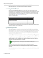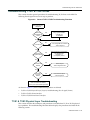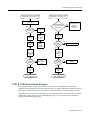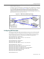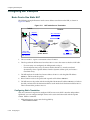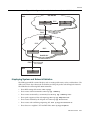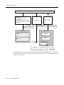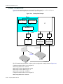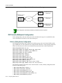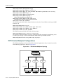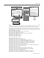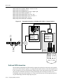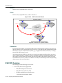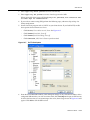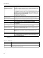
1
X-Pedition™ Security Router
XSR User’s Guide
Version 7.5
9033837-08
Electrical Hazard: Only qualified personnel should perform installation procedures.
Riesgo Electrico: Solamente personal calificado debe realizar procedimientos de instalacion.
Elektrischer Gefahrenhinweis: Installationen sollten nur durch ausgebildetes und qualifiziertes Personal
vorgenommen werden.
Notice
Enterasys Networks reserves the right to make changes in specifications and other information contained in this document and
its web site without prior notice. The reader should in all cases consult Enterasys Networks to determine whether any such
changes have been made.
The hardware, firmware, or software described in this document is subject to change without notice.
IN NO EVENT SHALL ENTERASYS NETWORKS BE LIABLE FOR ANY INCIDENTAL, INDIRECT, SPECIAL, OR
CONSEQUENTIAL DAMAGES WHATSOEVER (INCLUDING BUT NOT LIMITED TO LOST PROFITS) ARISING OUT OF
OR RELATED TO THIS DOCUMENT, WEB SITE, OR THE INFORMATION CONTAINED IN THEM, EVEN IF
ENTERASYS NETWORKS HAS BEEN ADVISED OF, KNEW OF, OR SHOULD HAVE KNOWN OF, THE POSSIBILITY OF
SUCH DAMAGES.
Enterasys Networks, Inc.
50 Minuteman Road
Andover, MA 01810
© 2004 Enterasys Networks, Inc. All rights reserved.
Part Number: 9033837-08 August 2004
ENTERASYS NETWORKS, ENTERASYS XSR, and any logos associated therewith, are trademarks or registered trademarks of
Enterasys Networks, Inc. in the United States and other countries. All other product names mentioned in this manual may be
trademarks or registered trademarks of their respective owners.
Documentation URL: http://www.enterasys.com/support/manuals
Documentacion URL: http://www.enterasys.com/support/manuals
Dokumentation http://www.enterasys.com/support/manuals
i
Regulatory Compliance Information
Federal Communications Commission (FCC) Notice
The XSR complies with Title 47, Part 15, Class A of FCC rules. Operation is subject to the following two conditions:
• This device may not cause harmful interference.
• This device must accept any interference received, including interference that may cause undesired operation.
NOTE: The XSR has been tested and found to comply with the limits for a class A digital device, pursuant to Part 15 of the FCC
rules. These limits are designed to provide reasonable protection against harmful interference when the XSR is operated in a
commercial environment. This XSR uses, generates, and can radiate radio frequency energy and if not installed in accordance
with the operator’s manual, may cause harmful interference to radio communications. Operation of the XSR in a residential
area is likely to cause interference in which case you will be required to correct the interference at your own expense.
WARNING: Modifications or changes made to the XSR, and not approved by Enterasys Networks may void the authority
granted by the FCC or other such agency to operate the XSR.
The XSR complies with Part 68 of the FCC rules and the requirements adopted by the Administrative Council for Terminal
Attachments (ACTA). A label on the circuit board of the Network Interface Module contains, among other information, a
product identifier in the format listed in the following table. If requested, this number must be provided to the telephone
company.
Product
Product Identifier
NIM-T1/E1-xx, NIM-CT1E1/PRI-xx
US: 5N5DENANET1
NIM-BRI-U-xx
US: 5N5DENANEBU
NIM-ADSL-AC-xx
US: 5N5DL02NEAA
NIM-DIRELAY-xx
US: 5N5DENANEDI
NIM-TE1-xx, NIM-CTE1-PRI-xx
US: 5N5DENANECT
A plug and jack used to connect the XSR to the premises wiring and telephone network must comply with the applicable FCC
Part 68 rules and requirements adopted by ACTA. Refer to the following table and installation instructions for details.
Product
Jack Used
NIM-T1/E1-xx, NIM-CT1E1/PRI-xx, RJ48C
NIM-DIRELAY-xx, NIM-TE1-xx,
NIM-CTE1-PRI-xx
NIM-BRI-U-xx
RJ49C
NIM-ADSL-AC-xx
RJ11C
Codes applicable to this equipment:
Product
Facilities Interface Code (FIC)
NIM-T1/E1-xx, NIM-CT1E1/PRI-xx, 04DU9.BN, 04DU9.DN,
04DU9.1KN, 04DU9.1SN
NIM-DIRELAY-xx, NIM-TE1-xx,
NIM-CTE1-PRI-xx
Service Order Code (SOC)
6.0N
NIM-BRI-U-xx
02IS5
6.0N
NIM-ADSL-AC-xx
02LS2
7.0Y
If the XSR harms the telephone network, the telephone company will notify you in advance that it may need to temporarily
discontinue service. But if advance notice is not practical, the telephone company will notify you as soon as possible. Also, you
will be advised of your right to file a complaint with the FCC if you believe it is necessary.
The telephone company may make changes in its facilities, equipment, operations, or procedures that could affect the operation
of the XSR. If this happens, the telephone company will provide advance notice for you to make necessary modifications and
maintain uninterrupted service.
If you experience trouble with the XSR, for repair or warranty information, please contact Enterasys Networks, Inc., at 978-6841000. If the XSR is causing harm to the telephone network, the telephone company may request that you disconnect the
equipment until the problem is solved. The XSR is not intended to be repaired by the customer.
ii
Industry Canada Notices
This digital apparatus does not exceed the class A limits for radio noise emissions from digital apparatus set out in the Radio
Interference Regulations of the Canadian Department of Communications.
Le présent appareil numérique n’émet pas de bruits radioélectriques dépassant les limites applicables aux appareils
numériques de la class A prescrites dans le Règlement sur le brouillage radioélectrique édicté par le ministère des
Communications du Canada.
Equipment Attachments Limitations
“NOTICE: The Industry Canada label identifies certified equipment. This certification means that the equipment meets
telecommunications network protective, operational and safety requirements as prescribed in the appropriate Terminal
Equipment Technical Requirements document(s). The department does not guarantee the equipment will operate to the user's
satisfaction.
Before installing this equipment, users should ensure that it is permissible to be connected to the facilities of the local
telecommunications company. The equipment must also be installed using an acceptable method of connection. The customer
should be aware that compliance with the above conditions may not prevent degradation of service in some situations.
Repairs to certified equipment should be coordinated by a representative designated by the supplier. Any repairs or alterations
made by the user to this equipment, or equipment malfunctions, may give the telecommunications company cause to request
the user to disconnect the equipment.
Users should ensure for their own protection that the electrical ground connections of the power utility, telephone lines and
internal metallic water pipe system, if present, are connected together. This precaution may be particularly important in rural
areas. Caution: Users should not attempt to make such connections themselves, but should contact the appropriate electric
inspection authority, or electrician, as appropriate.”
“NOTICE: The Ringer Equivalence Number (REN) assigned to each terminal device provides an indication of the maximum
number of terminals allowed to be connected to a telephone interface. The termination on an interface may consist of any
combination of devices subject only to the requirement that the sum of the ringer equivalence Numbers of all the devices does
not exceed 5."
R & TTE Directive Declaration
Hereby, Enterasys Networks, Inc. declares that this XSR-1850 X-Pedition Security Router is compliant with essential
requirements and other relevant provisions of Directive 1999/5/EC.
Class A ITE Notice
WARNING: This is a Class A product. In a domestic environment this product may cause radio interference in which case the
user may be required to take adequate measures.
Clase A. Aviso de ITE
ADVERTENCIA: Este es un producto de Clase A. En un ambiente doméstico este producto puede causar interferencia de radio
en cuyo caso puede ser requerido tomar medidas adecuadas.
Klasse A ITE Anmerkung
WARNHINWEIS: Dieses Produkt zählt zur Klasse A ( Industriebereich ). In Wohnbereichen kann es hierdurch zu
Funkstörungen kommen, daher sollten angemessene Vorkehrungen zum Schutz getroffen werden.
Product Safety
This product complies with the following: UL 60950, CSA C22.2 No. 60950, 73/23/EEC, EN 60950, EN 60825, IEC 60950.
Use the XSR with the Advanced Power Solutions (APS61ES-30) power supply included with the branch router. Enterasys
Networks strongly recommends that you use only the proper type of power supply cord set for the XSR. It should be a
detachable type, UL listed/CSA certified, type SJ or SJT, rated 250 V minimum, 7 amp with grounding-type attachment plug.
Maximum length is 15 feet (4.5 meters). The cord set should have the appropriate safety approval for the country in which the
equipment will be installed.
Seguridad del Producto
El producto de Enterasys cumple con lo siguiente: UL 60950, CSA C22.2 No. 60950, 73/23/EEC, EN 60950, EN 60825, IEC 60950.
Produktsicherheit
Dieses Produkt entspricht den folgenden Richtlinien: UL 60950, CSA C22.2 No. 60950, 73/23/EEC, EN 60950, EN 60825,
IEC 60950.
iii
Electromagnetic Compatibility (EMC)
This product complies with the following: 47 CFR Parts 2 and 15, CSA C108.8, 89/336/EEC, EN 55022, EN 55024, EN 61000-3-2,
EN 61000-3-3, AS/NZS CISPR 22, and VCCI V-3.
Compatibilidad Electromágnetica (EMC)
Este producto de Enterasys cumple con lo siguiente: 47 CFR Partes 2 y 15, CSA C108.8, 89/336/EEC, EN 55022, EN 55024,
EN 61000-3-2, EN 61000-3-3, AS/NZS CISPR 22, VCCI V-3.
Elektro- magnetische Kompatibilität ( EMC )
Dieses Produkt entspricht den folgenden Richtlinien: 47 CFR Parts 2 and 15, CSA C108.8, 89/336/EEC, EN 55022, EN 55024,
EN 61000-3-2, EN 61000-3-3, AS/NZS CISPR 22, VCCI V-3.
VCCI Notice
This is a class A product based on the standard of the Voluntary Control Council for Interference by Information Technology
Equipment (VCCI) V-3. If this equipment is used in a domestic environment, radio disturbance may arise. When such trouble
occurs, the user may be required to take corrective actions.
BSMI EMC Statement — Taiwan
This is a class A product. In a domestic environment this product may cause radio interference in which case the user may be
required to take adequate measures.
Declaration of Conformity
Application of Council Directive(s): 89/336/EEC
73/23/EEC
Manufacturer’s Name: Enterasys Networks, Inc.
Manufacturer’s Address:
50 Minuteman Road
Andover, MA 01810
USA
European Representative Address: Enterasys Networks, Ltd.
Nexus House, Newbury Business Park
London Road, Newbury
Berkshire RG14 2PZ, England
Conformance to Directive(s)/Product Standards: EC Directive 89/336/EEC
EN 55022
EN 55024
EC Directive 73/23/EEC
EN 60950
EN 60825
Equipment Type/Environment: Networking Equipment, for use in a Commercial
or Light Industrial Environment.
Enterasys Networks, Inc. declares that the equipment packaged with this notice conforms to the above directives.
iv
Australian Telecom
N826
WARNING: Do not install phone line connections during an electrical storm.
WARNING: Do not connect phone line until the interface has been configured through local management. The service
provider may shut off service if an un-configured interface is connected to the phone lines.
WARNING: The NIM-BRI-ST cannot be connected directly to outside lines. An approved channel service unit (CSU) must be
used for connection to the ISDN network. In some areas this CSU is supplied by the network provider and in others it must be
supplied by the user. Contact your service provider for details.
Federal Information Processing Standard (FIPS) Certification
The XSR has been submitted to the National Institute of Standards and Technology (NIST) for FIPS 140-2 certification and is
now officially listed on the NIST pre-validation list. For more information about the FIPS validation program, go to http://
csrc.nist.gov/cryptval/preval.htm. For the FIPS 140-1 and 140-2 Pre-Validation List, click on the [PDF] link at the top of the
page.
Independent Communications Authority of South Africa
This product complies with the terms of the provisions of section 54(1) of the Telecommunications Act (Act 103 of 1996) and the
Telecommunications Regulation prescribed under the Post Office Act (Act 44 of 1958).
TE-2002/195
TE-2002/190
APPROVED
APPROVED
TE-2003/112
TE-2003/113
APPROVED
APPROVED
SS/366.01
APPROVED
VPN Consortium Interoperability
The VPN Consortium’s (VPNC) testing program is an important source for certification of conformance to IPSec standards.
With rigorous interoperability testing, the VPNC logo program provides IPSec users even more assurance that the XSR will
interoperate in typical business environments. VPNC is the only major IPSec testing organization that shows both proof of
interoperability as well as the steps taken so that you can reproduce the tests.
v
Enterasys Networks, Inc.
Firmware License Agreement
BEFORE OPENING OR UTILIZING THE ENCLOSED PRODUCT,
CAREFULLY READ THIS LICENSE AGREEMENT.
This document is an agreement (“Agreement”) between the end user (“You”) and Enterasys Networks, Inc. on behalf of itself
and its Affiliates (as hereinafter defined) (“Enterasys”) that sets forth Your rights and obligations with respect to the Enterasys
software program/firmware installed on the Enterasys product (including any accompanying documentation, hardware or
media) (“Program”) in the package and prevails over any additional, conflicting or inconsistent terms and conditions
appearing on any purchase order or other document submitted by You. “Affiliate” means any person, partnership, corporation,
limited liability company, or other form of enterprise that directly or indirectly through one or more intermediaries, controls, or
is controlled by, or is under common control with the party specified. This Agreement constitutes the entire understanding
between the parties, and supersedes all prior discussions, representations, understandings or agreements, whether oral or in
writing, between the parties with respect to the subject matter of this Agreement. The Program may be contained in firmware,
chips or other media.
BY INSTALLING OR OTHERWISE USING THE PROGRAM, YOU REPRESENT THAT YOU ARE AUTHORIZED TO
ACCEPT THESE TERMS ON BEHALF OF THE END USER (IF THE END USER IS AN ENTITY ON WHOSE BEHALF YOU
ARE AUTHORIZED TO ACT, “YOU” AND “YOUR” SHALL BE DEEMED TO REFER TO SUCH ENTITY) AND THAT YOU
AGREE THAT YOU ARE BOUND BY THE TERMS OF THIS AGREEMENT, WHICH INCLUDES, AMONG OTHER
PROVISIONS, THE LICENSE, THE DISCLAIMER OF WARRANTY AND THE LIMITATION OF LIABILITY. IF YOU DO
NOT AGREE TO THE TERMS OF THIS AGREEMENT OR ARE NOT AUTHORIZED TO ENTER INTO THIS AGREEMENT,
ENTERASYS IS UNWILLING TO LICENSE THE PROGRAM TO YOU AND YOU AGREE TO RETURN THE UNOPENED
PRODUCT TO ENTERASYS OR YOUR DEALER, IF ANY, WITHIN TEN (10) DAYS FOLLOWING THE DATE OF RECEIPT
FOR A FULL REFUND.
IF YOU HAVE ANY QUESTIONS ABOUT THIS AGREEMENT, CONTACT ENTERASYS NETWORKS, LEGAL
DEPARTMENT AT (978) 684-1000.
You and Enterasys agree as follows:
1. LICENSE. You have the non-exclusive and non-transferable right to use only the one (1) copy of the Program provided in
this package subject to the terms and conditions of this Agreement.
2.
RESTRICTIONS. Except as otherwise authorized in writing by Enterasys, You may not, nor may You permit any third
party to:
(i)
Reverse engineer, decompile, disassemble or modify the Program, in whole or in part, including for reasons of error
correction or interoperability, except to the extent expressly permitted by applicable law and to the extent the parties
shall not be permitted by that applicable law, such rights are expressly excluded. Information necessary to achieve
interoperability or correct errors is available from Enterasys upon request and upon payment of Enterasys’ applicable
fee.
(ii) Incorporate the Program, in whole or in part, in any other product or create derivative works based on the Program, in
whole or in part.
(iii) Publish, disclose, copy, reproduce or transmit the Program, in whole or in part.
(iv) Assign, sell, license, sublicense, rent, lease, encumber by way of security interest, pledge or otherwise transfer the
Program, in whole or in part.
(v) Remove any copyright, trademark, proprietary rights, disclaimer or warning notice included on or embedded in any
part of the Program.
3.
APPLICABLE LAW. This Agreement shall be interpreted and governed under the laws and in the state and federal courts
of the Commonwealth of Massachusetts without regard to its conflicts of laws provisions. You accept the personal
jurisdiction and venue of the Commonwealth of Massachusetts courts. None of the 1980 United Nations Convention on
Contracts for the International Sale of Goods, the United Nations Convention on the Limitation Period in the International
Sale of Goods, and the Uniform Computer Information Transactions Act shall apply to this Agreement.
4.
EXPORT RESTRICTIONS. You understand that Enterasys and its Affiliates are subject to regulation by agencies of the
U.S. Government, including the U.S. Department of Commerce, which prohibit export or diversion of certain technical
products to certain countries, unless a license to export the Program is obtained from the U.S. Government or an exception
from obtaining such license may be relied upon by the exporting party.
If the Program is exported from the United States pursuant to the License Exception CIV under the U.S. Export
Administration Regulations, You agree that You are a civil end user of the Program and agree that You will use the Program
for civil end uses only and not for military purposes.
vi
If the Program is exported from the United States pursuant to the License Exception TSR under the U.S. Export
Administration Regulations, in addition to the restriction on transfer set forth in Sections 1 or 2 of this Agreement, You
agree not to (i) reexport or release the Program, the source code for the Program or technology to a national of a country in
Country Groups D:1 or E:2 (Albania, Armenia, Azerbaijan, Belarus, Bulgaria, Cambodia, Cuba, Estonia, Georgia, Iraq,
Kazakhstan, Kyrgyzstan, Laos, Latvia, Libya, Lithuania, Moldova, North Korea, the People’s Republic of China, Romania,
Russia, Rwanda, Tajikistan, Turkmenistan, Ukraine, Uzbekistan, Vietnam, or such other countries as may be designated by
the United States Government), (ii) export to Country Groups D:1 or E:2 (as defined herein) the direct product of the
Program or the technology, if such foreign produced direct product is subject to national security controls as identified on
the U.S. Commerce Control List, or (iii) if the direct product of the technology is a complete plant or any major component
of a plant, export to Country Groups D:1 or E:2 the direct product of the plant or a major component thereof, if such foreign
produced direct product is subject to national security controls as identified on the U.S. Commerce Control List or is subject
to State Department controls under the U.S. Munitions List.
5.
UNITED STATES GOVERNMENT RESTRICTED RIGHTS. The enclosed Program (i) was developed solely at private
expense; (ii) contains “restricted computer software” submitted with restricted rights in accordance with section 52.227-19
(a) through (d) of the Commercial Computer Software-Restricted Rights Clause and its successors, and (iii) in all respects is
proprietary data belonging to Enterasys and/or its suppliers. For Department of Defense units, the Program is considered
commercial computer software in accordance with DFARS section 227.7202-3 and its successors, and use, duplication, or
disclosure by the Government is subject to restrictions set forth herein.
6.
DISCLAIMER OF WARRANTY. EXCEPT FOR THOSE WARRANTIES EXPRESSLY PROVIDED TO YOU IN WRITING
BY Enterasys, Enterasys DISCLAIMS ALL WARRANTIES, EITHER EXPRESS OR IMPLIED, INCLUDING BUT NOT
LIMITED TO IMPLIED WARRANTIES OF MERCHANTABILITY, SATISFACTORY QUALITY, FITNESS FOR A
PARTICULAR PURPOSE, TITLE AND NON- INFRINGEMENT WITH RESPECT TO THE PROGRAM. IF IMPLIED
WARRANTIES MAY NOT BE DISCLAIMED BY APPLICABLE LAW, THEN ANY IMPLIED WARRANTIES ARE
LIMITED IN DURATION TO THIRTY (30) DAYS AFTER DELIVERY OF THE PROGRAM TO YOU.
7.
LIMITATION OF LIABILITY. IN NO EVENT SHALL ENTERASYS OR ITS SUPPLIERS BE LIABLE FOR ANY
DAMAGES WHATSOEVER (INCLUDING, WITHOUT LIMITATION, DAMAGES FOR LOSS OF BUSINESS, PROFITS,
BUSINESS INTERRUPTION, LOSS OF BUSINESS INFORMATION, SPECIAL, INCIDENTAL, CONSEQUENTIAL, OR
RELIANCE DAMAGES, OR OTHER LOSS) ARISING OUT OF THE USE OR INABILITY TO USE THE PROGRAM, EVEN
IF ENTERASYS HAS BEEN ADVISED OF THE POSSIBILITY OF SUCH DAMAGES. THIS FOREGOING LIMITATION
SHALL APPLY REGARDLESS OF THE CAUSE OF ACTION UNDER WHICH DAMAGES ARE SOUGHT.
THE CUMULATIVE LIABILITY OF ENTERASYS TO YOU FOR ALL CLAIMS RELATING TO THE PROGRAM, IN
CONTRACT, TORT OR OTHERWISE, SHALL NOT EXCEED THE TOTAL AMOUNT OF FEES PAID TO ENTERASYS BY
YOU FOR THE RIGHTS GRANTED HEREIN.
8.
AUDIT RIGHTS. You hereby acknowledge that the intellectual property rights associated with the Program are of critical
value to Enterasys and, accordingly, You hereby agree to maintain complete books, records and accounts showing (i) license
fees due and paid, and (ii) the use, copying and deployment of the Program. You also grant to Enterasys and its authorized
representatives, upon reasonable notice, the right to audit and examine during Your normal business hours, Your books,
records, accounts and hardware devices upon which the Program may be deployed to verify compliance with this
Agreement, including the verification of the license fees due and paid Enterasys and the use, copying and deployment of
the Program. Enterasys’ right of examination shall be exercised reasonably, in good faith and in a manner calculated to not
unreasonably interfere with Your business. In the event such audit discovers non-compliance with this Agreement,
including copies of the Program made, used or deployed in breach of this Agreement, You shall promptly pay to Enterasys
the appropriate license fees. Enterasys reserves the right, to be exercised in its sole discretion and without prior notice, to
terminate this license, effective immediately, for failure to comply with this Agreement. Upon any such termination, You
shall immediately cease all use of the Program and shall return to Enterasys the Program and all copies of the Program.
9.
OWNERSHIP. This is a license agreement and not an agreement for sale. You acknowledge and agree that the Program
constitutes trade secrets and/or copyrighted material of Enterasys and/or its suppliers. You agree to implement reasonable
security measures to protect such trade secrets and copyrighted material. All right, title and interest in and to the Program
shall remain with Enterasys and/or its suppliers. All rights not specifically granted to You shall be reserved to Enterasys.
10. ENFORCEMENT. You acknowledge and agree that any breach of Sections 2, 4, or 9 of this Agreement by You may cause
Enterasys irreparable damage for which recovery of money damages would be inadequate, and that Enterasys may be
entitled to seek timely injunctive relief to protect Enterasys’ rights under this Agreement in addition to any and all remedies
available at law.
vii
11. ASSIGNMENT. You may not assign, transfer or sublicense this Agreement or any of Your rights or obligations under this
Agreement, except that You may assign this Agreement to any person or entity which acquires substantially all of Your
stock or assets. Enterasys may assign this Agreement in its sole discretion. This Agreement shall be binding upon and inure
to the benefit of the parties, their legal representatives, permitted transferees, successors and assigns as permitted by this
Agreement. Any attempted assignment, transfer or sublicense in violation of the terms of this Agreement shall be void and
a breach of this Agreement.
12. WAIVER. A waiver by Enterasys of a breach of any of the terms and conditions of this Agreement must be in writing and
will not be construed as a waiver of any subsequent breach of such term or condition. Enterasys’ failure to enforce a term
upon Your breach of such term shall not be construed as a waiver of Your breach or prevent enforcement on any other
occasion.
13. SEVERABILITY. In the event any provision of this Agreement is found to be invalid, illegal or unenforceable, the validity,
legality and enforceability of any of the remaining provisions shall not in any way be affected or impaired thereby, and that
provision shall be reformed, construed and enforced to the maximum extent permissible. Any such invalidity, illegality or
unenforceability in any jurisdiction shall not invalidate or render illegal or unenforceable such provision in any other
jurisdiction.
14. TERMINATION. Enterasys may terminate this Agreement immediately upon Your breach of any of the terms and
conditions of this Agreement. Upon any such termination, You shall immediately cease all use of the Program and shall
return to Enterasys the Program and all copies of the Program.
viii
Contents
Preface
Contents of the Guide ..................................................................................................................................... xxv
Conventions Used in This Guide (Convenciones Usadas en Esta Guía) ...................................................... xxvi
Getting Help .................................................................................................................................................. xxvii
Chapter 1: Overview
Chapter 2: Managing the XSR
Utilizing the Command Line Interface ............................................................................................................. 2-5
Connecting via the Console Port .............................................................................................................. 2-5
Using the Console Port for Dial Backup ............................................................................................. 2-5
Using the Console Port to Remotely Control the XSR ....................................................................... 2-5
Connecting a Serial Interface to a Modem ......................................................................................... 2-6
Terminal Commands .......................................................................................................................... 2-7
Connecting via Telnet .............................................................................................................................. 2-7
Connecting via SSH ................................................................................................................................. 2-7
Accessing the Initial Prompt ..................................................................................................................... 2-8
Synchronizing the Clock ........................................................................................................................... 2-8
Managing the Session .............................................................................................................................. 2-9
Remote Auto Install .................................................................................................................................. 2-9
RAI Features and Requirements ........................................................................................................ 2-9
RAI Requirements on the XSR......................................................................................................... 2-11
How RAI Components Work............................................................................................................. 2-11
CLI Editing Rules ................................................................................................................................... 2-15
Setting CLI Configuration Modes ........................................................................................................... 2-16
User EXEC Mode ............................................................................................................................. 2-18
Privileged EXEC Mode ..................................................................................................................... 2-18
Global Configuration Mode .................................................................................................................... 2-18
Exiting From the Current Mode .............................................................................................................. 2-18
Mode Examples ..................................................................................................................................... 2-19
Observing Command Syntax and Conventions ..................................................................................... 2-19
CLI Command Limits ........................................................................................................................ 2-20
Describing Ports and Interfaces ............................................................................................................. 2-20
Supported Physical Interfaces .......................................................................................................... 2-20
Supported Virtual Interfaces ............................................................................................................. 2-20
Supported Ports................................................................................................................................ 2-20
Numbering XSR Slots, Cards, and Ports ............................................................................................... 2-21
Setting Port Configuration Mode ...................................................................................................... 2-21
Setting Interface Type and Numbering .................................................................................................. 2-21
Configuration Examples ................................................................................................................... 2-22
Entering Commands that Control Tables ............................................................................................... 2-24
Adding Table Entries ........................................................................................................................ 2-24
Deleting Table Entries ...................................................................................................................... 2-24
Modifying Table Entries .................................................................................................................... 2-25
Displaying Table Entries ................................................................................................................... 2-25
Managing XSR Interfaces ...................................................................................................................... 2-25
Enabling an Interface........................................................................................................................ 2-25
Disabling an Interface ....................................................................................................................... 2-26
ix
Configuring an Interface ................................................................................................................... 2-26
Displaying Interface Attributes .......................................................................................................... 2-26
Managing Message Logs ....................................................................................................................... 2-26
Logging Commands ......................................................................................................................... 2-27
Performing Fault Management ............................................................................................................... 2-27
Fault Report Commands .................................................................................................................. 2-28
Capturing Fault Report Data............................................................................................................. 2-28
Using the Real-Time Clock .................................................................................................................... 2-28
RTC/Network Clock Options............................................................................................................. 2-28
RTC Commands............................................................................................................................... 2-28
Managing the System Configuration ...................................................................................................... 2-29
Resetting the Configuration to Factory Default ...................................................................................... 2-29
Using the Default Button (XSR 1800/1200 Series Only) .................................................................. 2-29
Configuration Save Options ................................................................................................................... 2-30
Using File System Commands ......................................................................................................... 2-31
Bulk Configuration Management ............................................................................................................ 2-31
Downloading the Configuration ........................................................................................................ 2-31
Uploading the Configuration/Crash Report....................................................................................... 2-31
Creating Alternate Configuration Files.............................................................................................. 2-32
Managing the Software Image ............................................................................................................... 2-32
Creating Alternate Software Image Files .......................................................................................... 2-32
BootRom Upgrade Choices .............................................................................................................. 2-33
Loading Software Images ................................................................................................................. 2-38
Using EOS Fallback to Upgrade the Image...................................................................................... 2-38
Downloading with FIPS Security ...................................................................................................... 2-40
Software Image Commands ............................................................................................................. 2-40
Configuration Change Hashing ........................................................................................................ 2-40
Displaying System Status and Statistics ................................................................................................ 2-40
Memory Management ................................................................................................................................... 2-41
Creating Resources ............................................................................................................................... 2-41
Network Management through SNMP .......................................................................................................... 2-42
SNMP Informs ........................................................................................................................................ 2-42
Shaping Trap Traffic ............................................................................................................................... 2-43
Statistics ................................................................................................................................................. 2-43
Alarm Management (Traps) ................................................................................................................... 2-43
Network Monitoring via Service Level Agreement Agent ....................................................................... 2-43
Measuring Performance Metrics....................................................................................................... 2-44
Configuration Examples ................................................................................................................... 2-44
Using the SLA Agent in SNMP ......................................................................................................... 2-46
Full Configuration Backup/Restore ........................................................................................................ 2-47
Cabletron CTdownload MIB ............................................................................................................. 2-47
Enterasys Configuration Management MIB ...................................................................................... 2-47
Software Image Download using NetSight ............................................................................................. 2-47
CLI Translator................................................................................................................................... 2-48
Appending CLI Commands to Configuration Files via SNMP ................................................................ 2-48
Accessing the XSR Through the Web .......................................................................................................... 2-49
Network Management Tools ......................................................................................................................... 2-49
NetSight Atlas Router Services Manager v2.0 ....................................................................................... 2-49
Firmware Upgrade Procedures .............................................................................................................. 2-49
Using the CLI for Downloads............................................................................................................ 2-49
Using SNMP for Downloads ............................................................................................................. 2-49
Fault Reporting ....................................................................................................................................... 2-50
Auto-discovery ....................................................................................................................................... 2-50
x
Chapter 3: Managing LAN/WAN Interfaces
Overview of LAN Interfaces .......................................................................................................................... 3-51
LAN Features ............................................................................................................................................... 3-51
Configuring the LAN ..................................................................................................................................... 3-52
MIB Statistics ................................................................................................................................................ 3-52
Overview of WAN Interfaces ........................................................................................................................ 3-53
WAN Features .............................................................................................................................................. 3-53
Configuring the WAN .................................................................................................................................... 3-54
Chapter 4: Configuring T1/E1 & T3/E3 Interfaces
Overview ....................................................................................................................................................... 4-57
T1/E1 Functionality ................................................................................................................................ 4-57
T3/E3 Functionality ................................................................................................................................ 4-57
Features ....................................................................................................................................................... 4-57
T1/E1 Mode ............................................................................................................................................ 4-57
T3 Mode ................................................................................................................................................. 4-58
E3 Mode ................................................................................................................................................. 4-58
T1/E1 Subsystem Configuration ............................................................................................................ 4-59
T3/E3 Subsystem Configuration ............................................................................................................ 4-59
T1 Drop & Insert One-to-One DS0 Bypassing ....................................................................................... 4-60
Drop and Insert Features.................................................................................................................. 4-60
Configuring Channelized T1/E1 Interfaces ................................................................................................... 4-61
Configuring Un-channelized T3/E3 Interfaces .............................................................................................. 4-62
Troubleshooting T1/E1 & T3/E3 Links .......................................................................................................... 4-63
T1/E1 & T3/E3 Physical Layer Troubleshooting .................................................................................... 4-63
T1/E1 & T3/E3 Alarm Analysis ............................................................................................................... 4-65
Receive Alarm Indication Signal (AIS - Blue Alarm) ......................................................................... 4-65
Receive Remote Alarm Indication (RAI - Yellow Alarm)................................................................... 4-65
Transmit Remote Alarm Indication (RAI - Yellow Alarm).................................................................. 4-66
Transmit Sending Remote Alarm (Red Alarm) ................................................................................. 4-66
Transmit Alarm Indication Signal (AIS - Blue Alarm) ........................................................................ 4-66
T1/E1 & T3/E3 Error Events Analysis .................................................................................................... 4-67
Slip Seconds Counter Increasing ..................................................................................................... 4-68
Framing Loss Seconds Increasing ................................................................................................... 4-68
Line Code Violations Increasing ....................................................................................................... 4-69
Configuring the D&I NIM ........................................................................................................................ 4-69
Chapter 5: Configuring IP
Overview ....................................................................................................................................................... 5-71
General IP Features ..................................................................................................................................... 5-71
ARP and Proxy ARP .............................................................................................................................. 5-74
Proxy DNS ............................................................................................................................................. 5-74
BOOTP/DHCP Relay ............................................................................................................................. 5-74
Broadcast ............................................................................................................................................... 5-75
Directed Broadcast ........................................................................................................................... 5-75
Local Broadcast................................................................................................................................ 5-75
ICMP ...................................................................................................................................................... 5-75
TCP ........................................................................................................................................................ 5-76
UDP ........................................................................................................................................................ 5-76
Telnet ..................................................................................................................................................... 5-76
SSH ........................................................................................................................................................ 5-76
Trivial File Transfer Protocol (TFTP) ...................................................................................................... 5-77
IP Interface ............................................................................................................................................. 5-77
xi
Secondary IP .......................................................................................................................................... 5-78
Interface & Secondary IP.................................................................................................................. 5-78
ARP & Secondary IP ........................................................................................................................ 5-78
ICMP & Secondary IP....................................................................................................................... 5-79
Routing Table Manager & Secondary IP .......................................................................................... 5-79
OSPF & Secondary IP...................................................................................................................... 5-79
RIP & Secondary IP.......................................................................................................................... 5-79
Unnumbered Interface & Secondary IP............................................................................................ 5-79
NAT & Secondary IP ........................................................................................................................ 5-80
DHCP & Secondary IP ..................................................................................................................... 5-80
VPN & Secondary IP ........................................................................................................................ 5-80
VRRP & Secondary IP...................................................................................................................... 5-80
PPPoE & Secondary IP .................................................................................................................... 5-80
Maximum Transmission Unit (MTU) ....................................................................................................... 5-80
Ping ........................................................................................................................................................ 5-80
Traceroute .............................................................................................................................................. 5-81
IP Routing Protocols ..................................................................................................................................... 5-81
RIPv1 and v2 .......................................................................................................................................... 5-81
Triggered-on-Demand RIP ..................................................................................................................... 5-82
How Triggered-on-Demand RIP Works ............................................................................................ 5-83
OSPF ..................................................................................................................................................... 5-84
LSA Type 3 and 5 Summarization .................................................................................................... 5-85
OSPF Database Overflow ................................................................................................................ 5-86
OSPF Passive Interfaces ................................................................................................................. 5-87
OSPF Troubleshooting ........................................................................................................................... 5-87
Null Interface .......................................................................................................................................... 5-87
Route Preference ................................................................................................................................... 5-88
Static Routes .......................................................................................................................................... 5-89
VLAN Routing ........................................................................................................................................ 5-89
Forwarding VLAN, PPPoE over VLAN ............................................................................................. 5-90
VLAN Processing Over the XSR’s Ethernet Interfaces .................................................................... 5-91
VLAN Processing: VLAN-enabled Ethernet to Standard LAN Interfaces ......................................... 5-91
VLAN Processing: VLAN-enabled Ethernet to WAN Interfaces ....................................................... 5-92
VLAN Processing: WAN Interface to a VLAN-enabled Ethernet Interface ....................................... 5-92
QoS with VLAN................................................................................................................................. 5-92
Policy Based Routing ............................................................................................................................. 5-93
Accessing the Global Routing Policy Table ...................................................................................... 5-93
Match Clauses.................................................................................................................................. 5-93
Set Clauses ...................................................................................................................................... 5-93
PBR Cache ....................................................................................................................................... 5-94
Default Network ...................................................................................................................................... 5-94
Classless Inter-Domain Routing (CIDR) ................................................................................................ 5-95
Router ID ................................................................................................................................................ 5-95
Network Address Translation ................................................................................................................. 5-96
Features ........................................................................................................................................... 5-96
Virtual Router Redundancy Protocol ...................................................................................................... 5-97
VRRP Definitions .............................................................................................................................. 5-98
How the VRRP Works ...................................................................................................................... 5-99
Different States of a VRRP Router ................................................................................................... 5-99
VRRP Features .................................................................................................................................... 5-100
Multiple Virtual IP Addresses per VR ............................................................................................. 5-100
Multiple VRs Per Router ................................................................................................................. 5-100
Authentication................................................................................................................................. 5-101
Load Balancing ............................................................................................................................... 5-101
xii
ARP Process on a VRRP Router ................................................................................................... 5-101
Host ARP........................................................................................................................................ 5-101
Proxy ARP ...................................................................................................................................... 5-101
Gratuitous ARP............................................................................................................................... 5-101
Traffic Process on a VRRP Router ................................................................................................. 5-101
ICMP Ping ...................................................................................................................................... 5-102
Interface Monitoring ........................................................................................................................ 5-102
Watch Group Monitoring................................................................................................................. 5-103
Physical Interface and Physical IP Address Change on a VRRP Router ....................................... 5-104
Equal-Cost Multi-Path (ECMP) ............................................................................................................ 5-104
Configuration Considerations ......................................................................................................... 5-104
Configuring RIP Examples ......................................................................................................................... 5-105
Configuring Unnumbered IP Serial Interface Example ............................................................................... 5-107
Configuring OSPF Example ....................................................................................................................... 5-107
Configuring NAT Examples ........................................................................................................................ 5-108
Basic One-to-One Static NAT .............................................................................................................. 5-108
Configuring Static Translation ........................................................................................................ 5-108
Dynamic Pool Configuration ................................................................................................................. 5-109
Configuring Dynamic Pool Translation ........................................................................................... 5-109
Network Address and Port Translation ................................................................................................ 5-110
Configuring NAPT........................................................................................................................... 5-110
Configuring NAPT........................................................................................................................... 5-111
Multiple NAT Pools within an Interface ................................................................................................ 5-111
Static NAT within an Interface .............................................................................................................. 5-113
NAT Port Forwarding ........................................................................................................................... 5-114
Configuring Policy Based Routing Example ............................................................................................... 5-115
Configuring VRRP Example ....................................................................................................................... 5-115
Router XSRa .................................................................................................................................. 5-115
Router XSRb .................................................................................................................................. 5-116
Configuring VLAN Examples ...................................................................................................................... 5-116
Chapter 6: Configuring the Border Gateway Protocol
Features ..................................................................................................................................................... 6-117
Overview ..................................................................................................................................................... 6-117
Describing BGP Messages .................................................................................................................. 6-118
Open............................................................................................................................................... 6-118
Update ............................................................................................................................................ 6-119
Keepalive........................................................................................................................................ 6-119
Notification...................................................................................................................................... 6-119
Defining BGP Path Attributes ............................................................................................................... 6-119
AS Path .......................................................................................................................................... 6-120
Origin .............................................................................................................................................. 6-120
Next Hop......................................................................................................................................... 6-121
Local Preference ............................................................................................................................ 6-121
Weight ............................................................................................................................................ 6-123
Atomic Aggregate ........................................................................................................................... 6-123
Aggregator...................................................................................................................................... 6-124
Multi-Exit Discriminator ................................................................................................................... 6-124
Community ..................................................................................................................................... 6-125
BGP Path Selection Process ............................................................................................................... 6-127
BGP Routing Policy .............................................................................................................................. 6-127
Access Control Lists ....................................................................................................................... 6-128
Filter Lists ....................................................................................................................................... 6-128
xiii
Community Lists ............................................................................................................................. 6-128
Route Maps .................................................................................................................................... 6-128
Regular Expressions ...................................................................................................................... 6-129
Regular Expression Characters...................................................................................................... 6-129
Regular Expression Examples ....................................................................................................... 6-129
Peer Groups ................................................................................................................................... 6-130
Initial BGP Configuration ...................................................................................................................... 6-131
Adding BGP Neighbors ........................................................................................................................ 6-131
Resetting BGP Connections ................................................................................................................ 6-131
Synchronization .................................................................................................................................... 6-132
Address Aggregation ............................................................................................................................ 6-132
Route Flap Dampening ........................................................................................................................ 6-132
Recommendations for Route Flap Dampening .............................................................................. 6-133
Capability Advertisement ..................................................................................................................... 6-133
Route Refresh ...................................................................................................................................... 6-133
Scaling BGP ......................................................................................................................................... 6-134
Route Reflectors............................................................................................................................. 6-135
Confederations ............................................................................................................................... 6-136
Displaying System and Network Statistics ........................................................................................... 6-137
Configuring BGP Route Maps .................................................................................................................... 6-138
Configuring BGP Neighbors ................................................................................................................. 6-139
BGP Path Filtering by Neighbor Example ............................................................................................ 6-139
BGP Aggregate Route Examples ......................................................................................................... 6-140
Configuring BGP Confederations ......................................................................................................... 6-140
TCP MD5 Authentication for BGP Example ......................................................................................... 6-141
Configuring BGP Peer Groups ................................................................................................................... 6-141
IBGP Peer Group Example .................................................................................................................. 6-141
EBGP Peer Group Example ................................................................................................................. 6-142
BGP Community with Route Maps Examples ...................................................................................... 6-142
Chapter 7: Configuring PIM-SM and IGMP
Features ..................................................................................................................................................... 7-145
Differences with Industry-Standard Approach ...................................................................................... 7-145
IP Multicast Overview ................................................................................................................................. 7-146
Defining Multicast Group Addressing ................................................................................................... 7-146
Outlining IGMP Versions ...................................................................................................................... 7-147
Comparing Multicast Distribution Trees ............................................................................................... 7-147
Forwarding Multicast Traffic ................................................................................................................. 7-148
Describing the XSR’s IP Multicast Features ............................................................................................... 7-148
Group Membership Actions .................................................................................................................. 7-149
Sending and Receiving Queries and Reports ...................................................................................... 7-149
Sending a Query............................................................................................................................. 7-149
Receiving a Query .......................................................................................................................... 7-149
Receiving a Report ......................................................................................................................... 7-150
Source-Specific Forwarding Rules ................................................................................................. 7-150
Interoperating with Older IGMP Versions ............................................................................................. 7-150
Query Version Distinctions ............................................................................................................. 7-150
Behavior of Group Members Among Older Version Queriers ........................................................ 7-150
Behavior of Group Members Among Older Version Group Members ............................................ 7-150
Behavior of Multicast Routers Among Older Version Queriers ...................................................... 7-151
Behavior of Multicast Routers Among Older Version Group Members .......................................... 7-151
Describing the XSR’s PIM-SM v2 Features ................................................................................................ 7-151
Phase 1: Building a Shared Tree ......................................................................................................... 7-151
xiv
Phase 2: Building Shortest Path Tree Between Sender & RP ............................................................. 7-152
Phase 3: Building Shortest Path Tree Between Sender & Receiver .................................................... 7-153
Neighbor Discovery and DR Election ................................................................................................... 7-154
PIM Register Message ......................................................................................................................... 7-155
PIM Join/Prune Message ..................................................................................................................... 7-155
Bootstrap & Rendezvous Point ............................................................................................................ 7-155
Assert Processing ................................................................................................................................ 7-155
Source-Specific Multicast ..................................................................................................................... 7-156
PIM SM over Frame Relay ................................................................................................................... 7-156
PIM Configuration Examples ...................................................................................................................... 7-156
Chapter 8: Configuring PPP
Overview ..................................................................................................................................................... 8-159
PPP Features ............................................................................................................................................. 8-159
Link Control Protocol (LCP) ................................................................................................................. 8-160
Network Control Protocol (NCP) .......................................................................................................... 8-160
Authentication ...................................................................................................................................... 8-161
Password Authentication Protocol (PAP) ....................................................................................... 8-161
Challenge Handshake Authentication Protocol (CHAP) ................................................................. 8-161
Microsoft Challenge Handshake Protocol (MS-CHAP) .................................................................. 8-161
Link Quality Monitoring (LQM) ............................................................................................................. 8-162
Multilink PPP (MLPPP) ........................................................................................................................ 8-162
Multi-Class MLPPP .............................................................................................................................. 8-163
MLPPP Packet Fragmentation and Serialization Transmission Latency........................................ 8-164
Fragment Interleaving Over the Link .............................................................................................. 8-165
Multilink Head Format Negotiation ................................................................................................. 8-165
Events and Alarms ......................................................................................................................... 8-166
IP Control Protocol (IPCP) ................................................................................................................... 8-166
IP Address Assignment .................................................................................................................. 8-167
PPP Bandwidth Allocation/Control Protocols (BAP/BAPC) .................................................................. 8-167
Configuring PPP with a Dialed Backup Line ............................................................................................... 8-168
Configuring a Synchronous Serial Interface ............................................................................................... 8-168
Configuring a Dialed Backup Line .............................................................................................................. 8-169
Configuring the Dialer Interface ........................................................................................................... 8-169
Configuring the Physical Interface for the Dialer Interface ................................................................... 8-169
Configuring the Interface as the Backup Dialer Interface ..................................................................... 8-170
Configuring MLPPP on a Multilink/Dialer interface ..................................................................................... 8-171
Multilink Example ................................................................................................................................. 8-171
Dialer Example ..................................................................................................................................... 8-171
Configuring BAP ......................................................................................................................................... 8-172
Dual XSRs: One Router Using DoD with Call Request ........................................................................ 8-172
XSR1 Configuration ........................................................................................................................ 8-172
XSR2 Configuration ........................................................................................................................ 8-173
Dual XSRs: BAP Using Call/Callback Request .................................................................................... 8-174
XSR1 Configuration ........................................................................................................................ 8-174
XSR2 Configuration ........................................................................................................................ 8-174
Chapter 9: Configuring Frame Relay
Overview ..................................................................................................................................................... 9-177
Virtual Circuits ................................................................................................................................ 9-177
DLCIs.............................................................................................................................................. 9-177
DTEs............................................................................................................................................... 9-178
DCEs .............................................................................................................................................. 9-178
xv
Frame Relay Features ................................................................................................................................ 9-179
Multi-Protocol Encapsulation ................................................................................................................ 9-179
Address Resolution .............................................................................................................................. 9-180
Dynamic Resolution Using Inverse ARP .............................................................................................. 9-180
Controlling Congestion in Frame Relay Networks ...................................................................................... 9-180
Rate Enforcement (CIR) - Generic Traffic Shaping .............................................................................. 9-180
Discard Eligibility (DE) Bit .................................................................................................................... 9-181
Forward Explicit Congestion Notification (FECN) ................................................................................ 9-181
Backward Explicit Congestion Notification (BECN) .............................................................................. 9-181
Link Management Information (LMI) ........................................................................................................... 9-182
Sub-interfaces ............................................................................................................................................ 9-183
FRF.12 Fragmentation ............................................................................................................................... 9-183
End-to-End Fragmentation ................................................................................................................... 9-184
User Configuration Commands ............................................................................................................ 9-184
Map-Class Configuration ................................................................................................................ 9-185
Show Running Configuration .......................................................................................................... 9-185
Displaying Statistics........................................................................................................................ 9-185
Reports and Alarms ............................................................................................................................. 9-185
Clear Statistics ..................................................................................................................................... 9-185
Interconnecting via Frame Relay Network .................................................................................................. 9-186
Configuring Frame Relay ............................................................................................................................ 9-187
Multi-point to Point-to-Point Example ................................................................................................... 9-187
Chapter 10: Configuring Dialer Services
Overview of Dial Services ......................................................................................................................... 10-191
Dial Services Features ....................................................................................................................... 10-191
Asynchronous and Synchronous Support ................................................................................................ 10-192
AT Commands on Asynchronous Ports ............................................................................................. 10-192
V.25bis over Synchronous Interfaces ................................................................................................ 10-192
DTR Dialing for Synchronous Interfaces ............................................................................................ 10-193
Time of Day feature ............................................................................................................................ 10-193
Typical Use for Dial Services ............................................................................................................. 10-193
Ethernet Backup ................................................................................................................................. 10-193
Implementing Dial Services ...................................................................................................................... 10-194
Dialer Profiles ..................................................................................................................................... 10-194
Dialer Interface ................................................................................................................................... 10-195
Dialer Strings ...................................................................................................................................... 10-195
Dialer Pool .......................................................................................................................................... 10-195
Addressing Dialer Resources ............................................................................................................. 10-195
Configuring Encapsulation ................................................................................................................. 10-196
ISDN Callback .................................................................................................................................... 10-196
Configuring the Dialer Interface ......................................................................................................... 10-200
Creating and Configuring the Dialer Interface .............................................................................. 10-200
Configuring the Map Class ........................................................................................................... 10-201
Configuring the Physical Interface for the Dialer Interface ........................................................... 10-201
Sample Dialer Configuration .............................................................................................................. 10-201
Configuring ISDN Callback ................................................................................................................ 10-202
Point-to-Point with Matched Calling/Called Numbers ................................................................... 10-202
Point-to-Point with Different Calling/Called Numbers ................................................................... 10-202
Point-to-Multipoint with One Neighbor .......................................................................................... 10-202
Point-to-Multipoint with Multiple Neighbors .................................................................................. 10-202
Overview of Dial Backup .......................................................................................................................... 10-203
Dial Backup Features ......................................................................................................................... 10-203
Sequence of Backup Events .................................................................................................................... 10-203
xvi
Link Failure Backup Example ................................................................................................................... 10-204
Configuring a Dialed Backup Line ............................................................................................................ 10-204
Configuring the Dialer Interface ......................................................................................................... 10-204
Configuring the Physical Interface for the Dialer Interface ................................................................. 10-205
Configuring Interface as the Backup Dialer Interface ......................................................................... 10-205
Sample Configuration ......................................................................................................................... 10-206
Overview of Dial on Demand/Bandwidth on Demand .............................................................................. 10-207
Dialer Interface Spoofing .......................................................................................................................... 10-208
Dialer Watch ............................................................................................................................................. 10-208
Dialer Watch Behavior ....................................................................................................................... 10-209
Caveat ................................................................................................................................................ 10-210
Answering Incoming ISDN Calls ............................................................................................................... 10-210
Incoming Call Mapping Example ........................................................................................................ 10-211
Node A (Calling Node) Configuration ........................................................................................... 10-211
Node B (Called Node) Configuration ............................................................................................ 10-212
Node D (Calling Node) Configuration ........................................................................................... 10-212
Configuring DoD/BoD ............................................................................................................................... 10-213
PPP Point-to-Multipoint Configuration ................................................................................................ 10-214
Node A (Calling Node) Configuration ........................................................................................... 10-214
Node B (Called Node) Configuration ............................................................................................ 10-215
PPP Multipoint-to-Multipoint Configuration ........................................................................................ 10-215
Node A Configuration ................................................................................................................... 10-215
Node B Configuration ................................................................................................................... 10-216
PPP Point-to-Point Configurations ..................................................................................................... 10-216
Dial-in Routing for Dial on Demand Example ............................................................................... 10-217
Dial-out Routing for Dial on Demand Example ............................................................................. 10-217
PPP Point-to-Multipoint Configurations .............................................................................................. 10-218
Dial-out Router Example .............................................................................................................. 10-219
Dial-in Router Example................................................................................................................. 10-219
MLPPP Point-to-Multipoint Configuration ........................................................................................... 10-220
Node A (Calling Node) Configuration ........................................................................................... 10-220
Node B (Called Node) Configuration ............................................................................................ 10-221
MLPPP Point-to-Point Configurations ................................................................................................ 10-221
Dial-in Router Example................................................................................................................. 10-221
Dial-out Router Example .............................................................................................................. 10-222
MLPPP Point-to-Multipoint Configurations ......................................................................................... 10-222
Dial-out Router Example .............................................................................................................. 10-223
Dial-in Router Example................................................................................................................. 10-224
MLPPP Multipoint-to-Multipoint Configuration ................................................................................... 10-224
Node A Configuration ................................................................................................................... 10-224
Node B Configuration ................................................................................................................... 10-225
Switched PPP Multilink Configuration ...................................................................................................... 10-225
Bandwidth-on-Demand ...................................................................................................................... 10-225
Node A (Calling Node) Configuration ........................................................................................... 10-226
Node C (Called Node) Configuration ............................................................................................ 10-226
Backup Configuration ............................................................................................................................... 10-227
Backup Using ISDN ........................................................................................................................... 10-227
Node A (Backed-up Node) Configuration ..................................................................................... 10-227
Node C (Called Node) Configuration ............................................................................................ 10-228
Configuration for Backup with MLPPP Bundle ................................................................................... 10-229
Node A (Backed-up Node) Configuration ..................................................................................... 10-229
Node C (Called Node) Configuration ............................................................................................ 10-230
Configuration for Ethernet Failover .................................................................................................... 10-230
Configuration for Frame Relay Encapsulation ................................................................................... 10-231
xvii
Chapter 11: Configuring Integrated Services Digital Network
ISDN Features .......................................................................................................................................... 11-233
BRI Features ...................................................................................................................................... 11-234
PRI Features ...................................................................................................................................... 11-234
Understanding ISDN ................................................................................................................................. 11-234
Basic Rate Interface ........................................................................................................................... 11-235
Primary Rate Interface ....................................................................................................................... 11-235
B-Channels ........................................................................................................................................ 11-235
D-Channel .......................................................................................................................................... 11-235
D-Channel Standards ......................................................................................................................... 11-236
D-Channel Signaling and Carrier Networks ....................................................................................... 11-236
ISDN Equipment Configurations ........................................................................................................ 11-236
Bandwidth Optimization ..................................................................................................................... 11-237
Security .............................................................................................................................................. 11-237
Call Monitoring ................................................................................................................................... 11-238
ISDN Trace ........................................................................................................................................ 11-238
Trace Decoding ............................................................................................................................ 11-238
Q921 Decoding............................................................................................................................. 11-238
Q931 Decoding............................................................................................................................. 11-239
Decoded IEs ................................................................................................................................. 11-241
BRI NI-1, DMS100 & 5ESS SPID Registration............................................................................. 11-241
Terminal Endpoint Identifier (TEI) Management Procedures ....................................................... 11-241
ISDN Configuration ................................................................................................................................... 11-241
BRI (Switched) Configuration Model .................................................................................................. 11-242
PRI Configuration Model .................................................................................................................... 11-244
Leased-Line Configuration Model ...................................................................................................... 11-246
More Configuration Examples .................................................................................................................. 11-247
T1 PRI ................................................................................................................................................ 11-247
E1 PRI ................................................................................................................................................ 11-247
ISDN BRI ............................................................................................................................................ 11-247
BRI Leased Line ................................................................................................................................. 11-248
BRI Leased PPP ................................................................................................................................ 11-248
BRI Leased Frame Relay ................................................................................................................... 11-248
ISDN (ITU Standard Q.931) Call Status Cause Codes ............................................................................ 11-248
Chapter 12: Configuring Quality of Service
Overview ................................................................................................................................................... 12-251
Mechanisms Providing QoS ..................................................................................................................... 12-252
Traffic Classification ........................................................................................................................... 12-252
Describing the Class Map............................................................................................................. 12-253
Describing the Policy Map ............................................................................................................ 12-253
Queuing and Services ........................................................................................................................ 12-254
Describing Class-Based Weight Fair Queuing ............................................................................. 12-254
Configuring CBWFQ ..................................................................................................................... 12-255
Measuring Bandwidth Utilization .................................................................................................. 12-255
Describing Priority Queues........................................................................................................... 12-255
Configuring Priority Queues ......................................................................................................... 12-255
Describing Traffic Policing .................................................................................................................. 12-256
Configuring Traffic Policing........................................................................................................... 12-256
Class-based Traffic Shaping .............................................................................................................. 12-257
Traffic Shaping per Policy-Map .......................................................................................................... 12-258
Differences Between Traffic Policing and Traffic Shaping ................................................................. 12-259
Traffic Shaping and Queue Limit ........................................................................................................ 12-259
xviii
Congestion Control & Avoidance ....................................................................................................... 12-260
Describing Queue Size Control (Drop Tail) .................................................................................. 12-260
Describing Random Early Detection............................................................................................. 12-260
Describing Weighted Random Early Detection ............................................................................ 12-261
Configuration per Interface ................................................................................................................. 12-262
Suggestions for Using QoS on the XSR ............................................................................................ 12-263
QoS and Link Fragmentation and Interleaving (LFI) ................................................................................ 12-263
Configuring QoS with MLPPP Multi-Class ......................................................................................... 12-263
Configuring QoS with FRF.12 ............................................................................................................ 12-264
QoS with VLAN ......................................................................................................................................... 12-264
Traffic Classification ........................................................................................................................... 12-264
Describing VLAN QoS Packet Flow ................................................................................................... 12-265
VLAN Packet with Priority Routed out a Fast/GigabitEthernet Interface ...................................... 12-265
VLAN Packet with Priority Routed out a Serial Interface .............................................................. 12-265
Non-VLAN IP Packet Routed Out a Fast/GigabitEthernet Interface............................................. 12-266
QoS with VLAN Configuration Process .............................................................................................. 12-266
QoS on Input ............................................................................................................................................ 12-267
QoS on VPN ............................................................................................................................................. 12-267
QoS over VPN Features .................................................................................................................... 12-268
Configuring QoS on a Physical Interface ........................................................................................... 12-268
Configuring QoS on a Virtual Tunnel Interface .................................................................................. 12-268
QoS on a Virtual Interface Example ............................................................................................. 12-269
QoS and VPN Interaction ................................................................................................................... 12-272
Configuring the Shaper on the VPN Interface .............................................................................. 12-273
QoS Policy Configuration Examples ......................................................................................................... 12-274
Simple QoS on Physical Interface Policy ........................................................................................... 12-274
QoS for Frame Relay Policy ............................................................................................................... 12-275
QoS with MLPPP Multi-Class Policy .................................................................................................. 12-276
QoS with FRF.12 Policy ..................................................................................................................... 12-277
QoS with VLAN Policy ........................................................................................................................ 12-278
Input and Output QoS Policy .............................................................................................................. 12-278
Input QoS on Ingress to the Diffserv Domain Policy .......................................................................... 12-279
Chapter 13: Configuring ADSL
Overview ................................................................................................................................................... 13-281
Features ................................................................................................................................................... 13-281
PDU Encapsulation Choices .............................................................................................................. 13-282
PPP over ATM.............................................................................................................................. 13-282
PPP over Ethernet over ATM (Routed) ........................................................................................ 13-283
Routed IP over ATM ..................................................................................................................... 13-284
ADSL Limitations ................................................................................................................................ 13-285
ADSL Hardware ................................................................................................................................. 13-285
NIM Card ...................................................................................................................................... 13-285
ADSL on the Motherboard ............................................................................................................ 13-286
DSP Firmware .............................................................................................................................. 13-286
ADSL Data Framing ........................................................................................................................... 13-286
ATM Support ...................................................................................................................................... 13-286
Virtual Circuits .............................................................................................................................. 13-286
OAM Cells .................................................................................................................................... 13-287
Performance Monitoring ............................................................................................................... 13-287
Class of Service............................................................................................................................ 13-287
DSLAM Compatibility ......................................................................................................................... 13-287
Access Concentrator Restrictions ...................................................................................................... 13-287
xix
Inverse ARP ....................................................................................................................................... 13-288
QoS .................................................................................................................................................... 13-288
SNMP ................................................................................................................................................. 13-288
Configuration Examples ........................................................................................................................... 13-288
PPPoE .......................................................................................................................................... 13-288
PPPoA .......................................................................................................................................... 13-289
IPoA.............................................................................................................................................. 13-290
Chapter 14: Configuring the Virtual Private Network
VPN Overview .......................................................................................................................................... 14-291
Internet Security Issues ...................................................................................................................... 14-291
How a Virtual Private Network Works ................................................................................................ 14-292
Ensuring VPN Security with IPSec/IKE/GRE ........................................................................................... 14-292
GRE over IPSec ................................................................................................................................. 14-294
Defining VPN Encryption .................................................................................................................... 14-295
Describing Public-Key Infrastructure (PKI) ............................................................................................... 14-295
Digital Signatures ............................................................................................................................... 14-295
Certificates ......................................................................................................................................... 14-296
Machine Certificates for the XSR ....................................................................................................... 14-296
CA Hierarchies ................................................................................................................................... 14-297
Certificate Chains ............................................................................................................................... 14-297
RA Mode ............................................................................................................................................ 14-298
Pending Mode .................................................................................................................................... 14-299
Enroll Password ................................................................................................................................. 14-299
CRL Retrieval ..................................................................................................................................... 14-299
Renewing and Revoking Certificates ................................................................................................. 14-299
DF Bit Functionality .................................................................................................................................. 14-299
VPN Applications ...................................................................................................................................... 14-300
Site-to-Site Networks ......................................................................................................................... 14-301
Site-to-Central-Site Networks ............................................................................................................. 14-301
NAT Traversal .............................................................................................................................. 14-301
Client Mode .................................................................................................................................. 14-302
Network Extension Mode (NEM) .................................................................................................. 14-303
Remote Access Networks .................................................................................................................. 14-303
Using OSPF Over a VPN Network ..................................................................................................... 14-304
OSPF Commands ........................................................................................................................ 14-304
Configuring OSPF Over Site-to-Central Site in Client Mode ........................................................ 14-304
Configuring OSPF over Site-to-Central Site in Network Extension Mode .................................... 14-306
Server ........................................................................................................................................... 14-307
Client ............................................................................................................................................ 14-307
Configuring OSPF with Fail Over (Redundancy) .......................................................................... 14-307
Server 1 ........................................................................................................................................ 14-307
Server 2 ........................................................................................................................................ 14-308
Client ............................................................................................................................................ 14-308
Limitations .................................................................................................................................... 14-308
XSR VPN Features ................................................................................................................................... 14-308
VPN Configuration Overview .................................................................................................................... 14-310
Master Encryption Key Generation .................................................................................................... 14-310
ACL Configuration Rules .................................................................................................................... 14-311
Configuring ACLs ......................................................................................................................... 14-311
Selecting Policies: IKE/IPSec Transform-Sets ................................................................................... 14-312
Security Policy Considerations ..................................................................................................... 14-313
Configuring Policy......................................................................................................................... 14-313
xx
Creating Crypto Maps ........................................................................................................................ 14-314
Configuring Crypto Maps.............................................................................................................. 14-314
Authentication, Authorization and Accounting Configuration ............................................................. 14-315
AAA Commands ........................................................................................................................... 14-316
Configuring AAA ........................................................................................................................... 14-316
PKI Configuration Options .................................................................................................................. 14-317
Configuring PKI ............................................................................................................................ 14-318
PKI Certificate Enrollment Example ................................................................................................... 14-318
Interface VPN Options ....................................................................................................................... 14-321
VPN Interface Sub-Commands .................................................................................................... 14-322
Configuring a Simple VPN Site-to-Site Application .................................................................................. 14-322
Configuring the VPN Using EZ-IPSec ...................................................................................................... 14-324
EZ-IPSec Configuration ..................................................................................................................... 14-325
Configuration Examples ........................................................................................................................... 14-326
XSR with VPN - Central Gateway ...................................................................................................... 14-326
GRE Tunnel for OSPF ....................................................................................................................... 14-330
Tunnel A: XSR-3250 VPN GRE Site-to-Site Tunnel..................................................................... 14-330
Tunnel B: XSR-1805 VPN GRE Site-to-Site Tunnel..................................................................... 14-332
XSR/Cisco Site-to-Site Example ........................................................................................................ 14-334
Cisco Configuration ...................................................................................................................... 14-334
XSR Configuration........................................................................................................................ 14-335
Interoperability Profile for the XSR ........................................................................................................... 14-336
Scenario 1: Gateway-to-Gateway with Pre-Shared Secrets .............................................................. 14-336
Scenario 2: Gateway-to-Gateway with Certificates ............................................................................ 14-339
Chapter 15: Configuring DHCP
Overview of DHCP ................................................................................................................................... 15-343
Features ................................................................................................................................................... 15-343
DHCP Server Standards .................................................................................................................... 15-344
How DHCP Works .................................................................................................................................... 15-344
DHCP Services ......................................................................................................................................... 15-345
Persistent Storage of Network Parameters for Clients ....................................................................... 15-345
Temporary or Permanent Network Address Allocation ...................................................................... 15-345
Lease............................................................................................................................................ 15-345
Assigned Network Configuration Values to Clients: Options ............................................................. 15-345
Provisioning Differentiated Network Values by Client Class .............................................................. 15-346
BOOTP Legacy Support .................................................................................................................... 15-346
Nested Scopes: IP Pool Subsets ....................................................................................................... 15-346
Scope Caveat ..................................................................................................................................... 15-347
Manual Bindings ................................................................................................................................. 15-347
DHCP Client Services .............................................................................................................................. 15-348
Router Option ..................................................................................................................................... 15-348
Parameter Request List Option .......................................................................................................... 15-348
DHCP Client Interaction ..................................................................................................................... 15-348
Secondary Address Caveats ........................................................................................................ 15-348
Interaction with Remote Auto Install (RAI).................................................................................... 15-349
DHCP Client Timeouts ....................................................................................................................... 15-349
DHCP CLI Commands ............................................................................................................................. 15-350
DHCP Set Up Overview ........................................................................................................................... 15-351
Configuring DHCP Address Pools ..................................................................................................... 15-351
Configuring DHCP - Network Configuration Parameters ................................................................... 15-351
Configuration Steps .................................................................................................................................. 15-351
Create an IP Local Client Pool ........................................................................................................... 15-351
xxi
Create a Corresponding DHCP Pool ................................................................................................. 15-352
Configure DHCP Network Parameters ............................................................................................... 15-352
Enable the DHCP Server ................................................................................................................... 15-352
Optional: Set Up a DHCP Nested Scope ........................................................................................... 15-352
Optional: Configure a DHCP Manual Binding .................................................................................... 15-352
DHCP Server Configuration Examples ..................................................................................................... 15-353
Pool with Hybrid Servers Example ..................................................................................................... 15-353
Manual Binding Example ................................................................................................................... 15-353
Manual Binding with Class Example .................................................................................................. 15-353
BOOTP Client Support Example ........................................................................................................ 15-354
DHCP Option Examples ..................................................................................................................... 15-354
Chapter 16: Configuring Security on the XSR
Features ................................................................................................................................................... 16-355
Access Control Lists ........................................................................................................................... 16-355
ACL Violations Alarm Example..................................................................................................... 16-356
Packet Filtering .................................................................................................................................. 16-356
LANd Attack ....................................................................................................................................... 16-356
Smurf Attack ....................................................................................................................................... 16-357
Fraggle Attack .................................................................................................................................... 16-357
IP Packet with Multicast/Broadcast Source Address ......................................................................... 16-357
Spoofed Address Check .................................................................................................................... 16-357
SYN Flood Attack Mitigation .............................................................................................................. 16-357
Fragmented and Large ICMP Packets ............................................................................................... 16-357
Fragmented ICMP Traffic ............................................................................................................. 16-357
Large ICMP Packets..................................................................................................................... 16-358
Ping of Death Attack..................................................................................................................... 16-358
Spurious State Transition ................................................................................................................... 16-358
General Security Precautions ................................................................................................................... 16-358
AAA Services ............................................................................................................................................ 16-359
Connecting Remotely via SSH or Telnet with AAA Service ............................................................... 16-360
Firewall Feature Set Overview ................................................................................................................. 16-363
Reasons for Installing a Firewall ........................................................................................................ 16-363
Types of Firewalls .............................................................................................................................. 16-364
ACL and Packet Filter Firewalls ................................................................................................... 16-364
ALG and Proxy Firewalls .............................................................................................................. 16-365
Stateful Inspection Firewalls ......................................................................................................... 16-366
XSR Firewall Feature Set Functionality .................................................................................................... 16-366
Stateful Firewall Inspection (SFI).................................................................................................. 16-366
Filtering non-TCP/UDP Packets ................................................................................................... 16-366
Application Level Commands ....................................................................................................... 16-367
Application Level Gateway ........................................................................................................... 16-367
On Board URL Filtering ................................................................................................................ 16-368
Denial of Service (DoS) Attack Protection .................................................................................... 16-369
Alarm Logging .............................................................................................................................. 16-370
Alarms .......................................................................................................................................... 16-370
Authentication............................................................................................................................... 16-371
Firewall and NAT .......................................................................................................................... 16-372
Firewall and VPN .......................................................................................................................... 16-372
ACLs and Firewall ........................................................................................................................ 16-372
Dynamic Reconfiguration ............................................................................................................. 16-372
Firewall CLI Commands ........................................................................................................................... 16-373
Firewall Limitations ................................................................................................................................... 16-376
xxii
Pre-configuring the Firewall ...................................................................................................................... 16-377
Steps to Configure the Firewall ................................................................................................................ 16-377
Configuration Examples ........................................................................................................................... 16-378
XSR with Firewall ............................................................................................................................... 16-378
XSR with Firewall, PPPoE and DHCP ............................................................................................... 16-380
XSR with Firewall and VPN ................................................................................................................ 16-381
Firewall Configuration for VRRP ........................................................................................................ 16-387
Firewall Configuration for RADIUS Authentication and Accounting ................................................... 16-387
Configuring Simple Security ............................................................................................................... 16-388
RPC Policy Configuration ................................................................................................................... 16-389
Appendix A: Alarms/Events, System Limits, and Standard ASCII Table
Recommended System Limits ....................................................................................................................A-391
System Alarms and Events ........................................................................................................................A-393
Firewall and NAT Alarms and Reports .......................................................................................................A-404
Standard ASCII Character Table ................................................................................................................A-409
Appendix B: XSR SNMP Proprietary and Associated Standard MIBs
Service Level Reporting MIB Tables ..........................................................................................................B-411
etsysSrvcLvlMetricTable.................................................................................................................B-411
etsysSrvcLvlOwnerTable ................................................................................................................B-412
etsysSrvcLvlHistoryTable ...............................................................................................................B-412
etsysSrvcLvlNetMeasureTable .......................................................................................................B-413
etsysSrvcLvlAggrMeasureTable .....................................................................................................B-414
BGP v4 MIB Tables ....................................................................................................................................B-415
General Variables Table .................................................................................................................B-415
BGP v4 Peer Table.........................................................................................................................B-415
BGP-4 Received Path Attribute Table ............................................................................................B-417
BGP-4 Traps...................................................................................................................................B-418
Firewall MIB Tables ....................................................................................................................................B-419
Global Interface Operations .................................................................................................................B-419
Monitoring Objects ...............................................................................................................................B-420
Policy Rule Table Totals Counters .................................................................................................B-420
Policy Rule True Table ...................................................................................................................B-420
Session Totals Counters ................................................................................................................B-420
Session Totals Table ......................................................................................................................B-420
IP Session Counters.......................................................................................................................B-421
IP Session Table ............................................................................................................................B-421
Authenticated Address Counters....................................................................................................B-421
Authenticated Addresses Table......................................................................................................B-422
DOS Attacks Blocked Counters......................................................................................................B-422
DOS Attacks Blocked Table ...........................................................................................................B-422
VPN MIB Tables .........................................................................................................................................B-422
etsysVpnIkePeer Table ..................................................................................................................B-423
etsysVpnIkePeerProposals Table ..................................................................................................B-423
etsysVpnIkeProposal Table ............................................................................................................B-424
etsysVpnIpsecPolicy Table.............................................................................................................B-424
etsysVpnIntfPolicy Table ................................................................................................................B-425
etsysVpnIpsecPolicyRule Table .....................................................................................................B-425
etsysVpnIpsecPolProposals Table .................................................................................................B-425
etsysVpnIpsecProposal Table ........................................................................................................B-426
etsysVpnIpsecPropTransforms Table ............................................................................................B-426
etsysVpnAhTransform Table ..........................................................................................................B-427
xxiii
etsysVpnEspTransform Table ........................................................................................................B-427
etsysVpnIpcompTransform Table...................................................................................................B-427
ipCidrRouteTable for Static Routes ............................................................................................................B-428
Host Resources MIB Objects .....................................................................................................................B-428
Enterasys Configuration Management MIB ................................................................................................B-429
Enterasys Configuration Change MIB ........................................................................................................B-430
Enterasys SNMP Persistence MIB .............................................................................................................B-431
Enterasys Syslog Client MIB ......................................................................................................................B-432
xxiv
Preface
This guide provides a general overview of the XSR hardware and software features. It describes
how to configure and maintain the router. Refer to the XSR CLI Reference Guide and the XSR
Getting Started Guide for information not contained in this document.
This guide is written for administrators who want to configure the XSR or experienced users who
are knowledgeable of basic networking principles.
Contents of the Guide
Information in this guide is arranged as follows:
•
Chapter 1, Overview, introduces key features of the XSR.
•
Chapter 2, Managing the XSR, describes the three methods of managing the router along with
the control commands and tools available to accomplish that task including Remote Auto
Install (RAI) and memory management.
•
Chapter 3, Managing LAN/WAN Interfaces, describes system FastEthernet/GigabitEthernet and
High Speed Serial features, how to configure them, and MIB-II statistics collected for LAN
interfaces.
•
Chapter 4, Configuring T1/E1 & T3/E3 Interfaces, outlines XSR controller features, including the
Drop and Insert NIM, and how to configure and troubleshoot them.
•
Chapter 5, Configuring IP, outlines a host of XSR IP protocol suite features, including Secondary
IP, VRRP, Proxy DNS, VLAN and Policy Based routing, Route Preference, multiple static
routes, CIDR, and their associated configuration.
•
Chapter 6, Configuring the Border Gateway Protocol, describes XSR-supported BGP-4 features
including MIB tables defined in RFC-1657, BGP SNMP traps, protection of sessions,
capabilities advertisement, route reflection, communities, route refresh, route flap dampening,
AS confederations, and debug capability.
•
Chapter 7, Configuring PIM-SM and IGMP, describes Protocol Independent Multicast - Sparse
Mode (PIM-SM) and Internet Group Management Protocol (IGMP) configuration with these
features and how to configure them: IGMP versions 1, 2 and 3 (on LAN interface only), PIMSM version 2, Static IGMP group membership, Dynamic and Static RP, Register and Assert
Mechanism, Rendezvous Point Tree (RPT) Build-up, Shortest Path Tree (SPT) Build-up, RPT to
SPT Switch, Join/Prune Mechanism, and Source Specific Multicast (SSM) Support.
•
Chapter 8, Configuring PPP, details XSR support for the PPP and Multi-link PPP protocols,
Multi-Class MLPPP, peer entity authentication, Bandwidth on Command (BAP), and how to
configure these features.
•
Chapter 9, Configuring Frame Relay, details how to set up Frame Relay networks on the XSR,
including using rate enforcement (CIR) and congestion control (FECN and BECN), Discard
Eligibility, Frame Relay Inverse ARP, LMI support, and FRF.12 fragmentation.
•
Chapter 10, Configuring Dial Services and Back Up, details background information about Dial
Services and Dial Backup across a PSTN, Ethernet failover, Dial on Demand (DoD) and
XSR User’s Guide
xxv
Conventions Used in This Guide (Convenciones Usadas en Esta Guía)
Bandwidth on Demand (BoD), Multi-link PPP, dialer interface spoofing, Dialer Watch, ISDN
callback, and the commands to configure these features.
•
Chapter 11, Configuring ISDN, outlines how to set up the Integrated Services Digital Network
protocol on the XSR for BRI, PRI and leased line applications. ISDN protocol tracing and
partial decoding of Q921 and Q931 frames is also described.
•
Chapter 12, Configuring Quality of Service, describes XSR support for QoS, including Random
Early Detection (RED), Weighted Random Early Detection (WRED), tail-drop, DSCP, IP
precedence, traffic policing and shaping, priority and CBWFQ queuing, and class-based traffic
shaping.
•
Chapter 13, Configuring ADSL, details ADSL line operation over POTS and ISDN circuits,
ADSL data framing format ATM Frame UNI, OAM cell behavior, PDU encapsulation choices:
PPP over ATM (PPPoA), PPP over Ethernet (PPPoE), and Routed IP over ATM (IPoA).
•
Chapter 14, Configuring the Virtual Private Network, outlines XSR support for Site-to-Site, Site-toCentral-Site, and Remote Access VPN applications. Other supported functionality includes
RADIUS authentication, PKI authentication, NAT traversal, IP address management, dynamic
routing over VPN (remote access only), digital signature and certificate support, GRE over
IPSec, and AAA.
•
Chapter 15, Configuring DHCP, details the router’s support for the Dynamic Host
Configuration Protocol including dynamic and manual IP address allocation, persistent
storage of client values, temporary or permanent network address allocation, and nested
scopes.
•
Chapter 16, Configuring Security on the XSR, describes methods to protect the router against
hacker attacks and install strong security including ACLs, AAA service, firewall, and how to
configure these features.
•
Appendix A, Alarms/Events and System Limits, lists the high, medium and low severity alarms
and events captured by the XSR as well as system limits for various XSR functions as a
function of installed memory.
•
Appendix B, SNMP Proprietary and Associated Standard MIBs, lists and describes XSR-supported
SNMP tables and objects for the following standard (partial listing) and proprietary MIBS.
Conventions Used in This Guide (Convenciones Usadas en Esta Guía)
The following conventions are used in this guide (Las siguientes convenciones son usadas en esta
guía):
Note: Calls the reader’s attention to any item of information that may be of special importance.
Nota: Llama la atencion del lector a cierta información que puede ser de especial importancia.
Caution: Contains information essential to avoid damage to the equipment.
Cautela: Contiene información esencial para prevenir dañar el equipo.
Achtung: Verweißt auf wichtige Informationen zum Schutz gegen Beschädigungen.
xxvi
Preface
Getting Help
Electrical Hazard: Warns against an action that could result in personal injury or death due to an
electrical hazard.
Riesgo Electrico: Advierte contra una acción que pudiera resultar en lesión corporal o la muerte
debido a un riesgo eléctrico.
Elektrischer Gefahrenhinweis: Installationen sollten nur durch ausgebildetes und qualifiziertes.
Personal vorgenommen werden.
Warning: Warns against an action that could result in personal injury or death.
Advertencia: Advierte contra una acción que pudiera resultar en lesión corporal o la muerte.
Warnhinweis: Warnung vor Handlungen, die zu Verletzung von Personen oder gar Todesfällen
führen können!
Bold/En negrilla
Text in boldface indicates values you type using the keyboard or select
using the mouse (for example, a:\setup). Default settings may also appear
in bold.
El texto en negrilla indica valores que usted introduce con el teclado o que
selecciona con el mouse (por ejemplo, a:\setup). Las configuraciones
default pueden también aparecer en en negrilla.
Italics/It áli ca
Text in italics indicates a variable, important new term, or the title of a
manual.
El texto en itálica indica un valor variable, un importante nuevo término, o
el título de un manual.
SMALL CAPS/
MAYUSCULAS
Small caps specify the keys to press on the keyboard; a plus sign (+)
between keys indicates that you must press the keys simultaneously (for
example, CTRL+ALT+DEL).
Las mayusculas indican las teclas a oprimir en el teclado; un signo de más
(+) entre las teclas indica que usted debe presionar las teclas
simultáneamente (por ejemplo, CTRL+ALT+DEL).
Courier font/
Tipo de letra Courier
Text in this font denotes a file name or directory.
El texto en este tipo de letra denota un nombre de archivo o de directorio.
Points to text describing CLI command.
Apunta al texto que describe un comando de CLI.
FastEthernet
FastEthernet and GigabitEthernet references are generally
interchangeable throughout this guide.
Las referencias a los terminos FastEthernet y GigabitEthernet son
generalmente intercambiables en el contenido de esta guia.
Getting Help
For additional support related to the XSR, contact Enterasys Networks by one of these methods:
World Wide Web
http://www.enterasys.com
Phone
(978) 684-1000
1-800-872-8440 (toll-free in U.S. and Canada)
For the Enterasys Networks Support toll-free number in your country:
http://www.enterasys.com/support/gtac-all.html
XSR User’s Guide
xxvii
Getting Help
Internet mail
[email protected]
To expedite your message, please type [xsr] in the subject line.
FTP
Login
Password
ftp://ftp.enterasys.com
anonymous
your Email address
Acquire the latest image and
Release Notes
http://www.enterasys.com/download
Additional documentation
http://www.enterasys.com/support/manuals
Forward comments or
suggestions
[email protected]
To expedite your message, type [techwriting] in the subject line, and
include the document Part Number in the Email.
Before contacting Enterasys Networks for technical support, have the following information
ready:
xxviii
Preface
•
Your Enterasys Networks service contract number
•
A description of the failure
•
A description of any action(s) already taken to resolve the problem (e.g., rebooting the unit,
reconfiguring modules, etc.)
•
The serial and revision numbers of all relevant Enterasys Networks products in the network
•
A description of your network environment (layout, cable type, etc.)
•
Network load and frame size at the time of the problem
•
The XSR’s history (i.e., have you returned the device before, is this a recurring problem, etc.)
•
Any previous Return Material Authorization (RMA) numbers
1
Overview
This chapter briefly describes the functionality of the XSR. Refer to the following chapters in this
manual for details on how to configure this functionality and the XSR CLI Reference Guide for a
description of associated CLI commands and examples.
The following functionality is supported on the XSR:
•
System Management - The XSR’s resources can be managed via four methods: the Command
Line Interface (CLI) for full configuration, performance and fault management; the Simple
Network Management Protocol including SNMP v1/v2c/v3 agent, for remote monitoring;
the NetSight Atlas Router Services Manager application for firewall and ACL configuration;
and the Web to gather version information. These tools control the XSR’s many hardware and
software facilities. Also supported: memory management, SSH v2 server, full configuration
backup and restore, EOS Fallback for reliable image upgrades, Simple Network Time Protocol
(SNTP v3) client and server (unicast mode) external source synchronization, login banner, and
a host of proprietary and standard MIBs including Download, Syslog, Configuration
Management, Configuration Change, Timed Reset, Chassis, Persistence, Host Resource,
Enterprise Firewall and VPN, and Protocol MIBs (OSPF, RIP, Frame Relay, and PPP), SNMP
Informs and Service Level Agreement (SLA) agents. The XSR’s SNMP MIBs support readable
checksums on XSR configurations and the Enterasys Configuration Management MIB will TFTP
a file on-the-fly to the XSR Flash, load the file to running config and save it to startup-config. The
XSR also supports placing a hostname in the Syslog message header and configuring multiple
Syslog servers.
•
Remote Auto Install (RAI) - automatically retrieves a centrally managed configuration
specifically created for a remote XSR by one of three methods: over a Frame Relay network
using the lowest numbered serial port, a PPP connection using the lowest numbered serial
port, or over an ADSL connection.
•
Ethernet Interfaces - The XSR 1800 Series’ two 10/100 Base-T FastEthernet interfaces and XSR
3000 Series’ three 10/100/1000 BaseT GigabitEthernet interfaces handle the router’s LAN
traffic stream, with support for alarms and events, diagnostics, packet filtering and statistics
gathering, and Ethernet backup.
•
T1/E1 & T3/E3 Interfaces - The XSR’s T1/E1 and T3/E3 subsystem on NIM-based I/O cards
handle the router’s WAN traffic with support for alarm detection and signaling, diagnostics,
line encoding, the Drop & Insert NIM, and a host of other functionality.
•
Serial Interface - The XSR’s NIM serial interface typically supports PPP providing both
asynchronous and synchronous protocol support. The XSR’s Console port can also be used as
a Serial connection to the router for remote or backup dialin.
•
PPP (WAN) -The Point-to-Point Protocol (PPP) provides a standard method for transporting
multi-protocol datagrams over point-to-point links. PPP defines procedures for the
assignment and management of network addresses, asynchronous and synchronous
encapsulation, link configuration, link quality testing, network protocol multiplexing, error
detection, and option negotiation for such capabilities as network-layer address negotiation
XSR User’s Guide
1-1
and data-compression negotiation. Also supported: PPPoE client and sub-interface
monitoring, and Multilink PPP protocols as well as Dial on Demand (DoD), Bandwidth on
Demand (BoD), Multi-Class MLPPP.
1-2
Overview
•
IP Protocol - IP supports interconnected systems of packet-switched computer communication
networks. It uses a 32-bit addressing scheme where an IP address is represented by four fields,
each containing 8-bit numbers. Also supported: secondary IP addressing, CIDR, the Virtual
Router Redundancy Protocol (VRRP), Proxy DNS, VLAN and Policy Based routing, Route
Preference, multiple static routes, and AAA, PPP and OSPF debugging.
•
DHCP - The XSR supports DHCP Server and Client on the trusted LAN to provide IP
addresses to computers on a customer's private LAN segment, temporary or permanent
network (IP) address and network configuration parameter assignment to clients, persistent
storage/database of network values for network clients - Bindings Database, persistent
storage of network client lease states kept after a system reboot, persistent and usercontrollable conflict avoidance to prevent duplicate IP address including configurable ping
checking, and visibility of DHCP network activity and leases through operator reports
statistics and logs.
•
Network Address Translation - static NAT, Network Address Port Translation (NAPT) and
dynamic NAT by source/destination IP address, dynamic NAT pool mapping with overload,
PPTP/GRE ALG and arbitrary IP address for NAPT, on the interface and port-forwarded
static NAT, multiple NATs on an interface.
•
IP Routing - The XSR supports RIP, OSPF and BGP4 dynamic routing, a vital function of the IP
protocol. Stored in a routing table, network data is used to determine the route for each packet
passing through the XSR. Also supported: route redistribution between OSPF and RIP, static
routes, multiple static routes to the same destination with different hops and distances,
Virtual Router Redundancy Protocol (VRRP) for default router redundancy and load
balancing, DNS proxy, Virtual Area Networks (VLAN 802.1Q), priority VLAN routing 802.1P,
policy based routing, route preference, multiple static routes, Protocol Independent Multicast
- Sparse Mode (PIM-SM), and configurable RIP and OSPF poll timers.
•
Equal-Cost Multi-Path (ECMP) - per packet and per flow (round robin) support for OSPF, BGP
and static routes (RIP excluded).
•
Border Gateway Protocol v4 - The XSR supports the following the BGP-4 features: all MIB tables
defined in RFC-1657 including BGP SNMP traps, protection of BGP sessions, capabilities
advertisement, route reflection, communities, route refresh, route flap dampening, AS
confederations, debugging, per neighbor configurable BGP timer and filter tags.
•
PIM/IGMP - Protocol Independent Multicast - Sparse Mode (PIM-SM) and Internet Group
Management Protocol (IGMP) is supported with the following features: IGMP versions 1, 2
and 3 (on LAN interface only), PIM-SM version 2, static IGMP group membership, dynamic
RP (BootStrap without Admin Scope Zone support), static RP, register and assert mechanism,
Rendezvous Point Tree (RPT) and Shortest Path Tree (SPT) Build-up, RPT to SPT Switch,
Join/Prune Mechanism, and Source Specific Multicast (SSM).
•
Frame Relay - The XSR provides this fast-packet switching method for wide-area networking.
Acting as a DTE, the router encapsulates data in a frame and transmits that data while serving
as a source device. When it is a destination device, it receives frames and de-encapsulates
them. The XSR’s implementation of Frame Relay employs DTE support of the User Network
Interface (UNI) for PVC (DLCI) connections with Committed Information Rate (CIR) traffic
shaping, BECN/FECN congestion control, standard LMIs ILMI, ANSI Annex D, CCITT
Annex A, FRF.12 fragmentation, periodic keep-alives, multi-protocol interconnect over Frame
Relay, Frame Relay Inverse ARP, multiple logical interfaces over the same physical port, QoS
including standard FIFO queuing or IP QoS on DLCIs, DCE support, and Frame Relay over
ISDN.
•
Quality of Service - The XSR provides traffic classification using IP Precedence and DSCP bits,
bandwidth control via metered, policed and prioritized traffic queues, and queue
management utilizing Tail Drop, Random and Weighted Early Detection (RED, WRED). Also,
QoS on Input including classification based on class maps (similar to QoS on Output), marking
per traffic flow (DSCP and IP precedence fields), and policing per traffic class, and QoS over
VPN.
•
ADSL - Three PDU encapsulation types are available for ADSL: PPP over ATM (PPPoA), PPP
over Ethernet (PPPoE), and Routed IP over ATM (IPoA). Also supported: POTS and ISDN
circuit support, ATM Frame UNI (FUNI) data framing format, OAM cells: AIS, RDI, CC,
Loopback over F4 and F5 flows, up to 30 ATM Permanent Virtual Circuits (PVCs), ATM UBR
traffic class, ATM Adaption Layers 0, 5, response to inverse ARP requests, and maintenance of
SNMP Interface and Interface Stack tables.
•
Virtual Private Network - The XSR supports VPN tunnels using L2TP, PPP or IPSec protected
by DES, 3DES, RC4, MD5, AES or SHA-1 encryption. VPN tunnels are authenticated/
authorized for credentials using pre-shared keys or Public Key Infrastructure (PKI) certificates
(Microsoft and Verisign). Also supported: DF Bit override, OSPF over VPN, GRE over IPSec,
interaction between firewall/NAT/VPN, ToS bit preservation, IP helper on VPN interfaces,
IETF/Microsoft-compatible NAT traversal for L2TP, and QoS over VPN.
•
Security - In its firewall feature set, the XSR provides stateful firewall protection against a
variety of Denial of Service attacks, FTP and H.323 ALG support, application command
filtering for FTP, SMTP, NNTP, HTTP, onboard URL filtering, firewall logging and
authentication, and supports standard and extended Access Control Lists to manage network
access. Also supported: AAA for firewall, Console/Telnet and SSHv2 users, and dynamic
reconfiguration of firewall policy without having to restart the code.
•
Dialer Interface - Dial Services are a cost-saving alternative to the leased line connection
between two peers and they can be implemented for different types of media for both
inbound and outbound connections. The XSR supports incoming calls on analog modems.
•
Dial Backup - The dialed backup feature provides a backup link over a dial line. The backup
link is brought up when a failure occurs in a primary link, and it is brought down when the
primary link is restored. This feature is supported for PPPoE to enable cable backup over
FastEthernet/GigabitEthernet sub-interfaces. Also supported: Dialer Watch, ISDN callback,
and dialer interface spoofing.
•
ISDN - The XSR’s BRI and PRI switched and leased lines set up and tear down calls, usually
under the control of the Dialer. The XSR’s ISDN services BRI and PRI lines with a 1, 2 or 4 port
Channelized NIM card for PRI lines, 1 or 2 port BRI-S/T NIM card, or 1 or 2 port BRI U NIM
card. Also supported: Circuit Mode Data (CMD) channel (DS0s) switching by the CO to the
destination user for the duration of the call, outgoing calls supported for Backup, DoD/BoD,
incoming calls routed to the correct protocol stack based on called number/sub-address and
calling number/sub-address, permanent B-channel support, i.e. 64 or 128 kbps lease line (each
BRI port can be set for CMD or Leased-Line mode of operation), BRI supported switches:
ETSI, TEI auto-negotiated for BRI, automatic configuration of Q.921/Q.931 (Layer 2/Layer 3)
by selection of switch type, PRI supported switches: ETSI, NI, DMS100, NTT, automatic
configuration of PRI restart and maintenance modes, Fixed TEI of 0 for PRI, ISDN switched
and leased line connections, bandwidth optimization through Dial on Demand (DoD),
Bandwidth on Demand (BoD) and Bandwidth Allocation Protocol (BAP), security through
caller ID, call monitoring, ISDN callback, Multilink PPP (MLPPP), per call activation for NTT
switches, and Frame Relay over ISDN. The XSR also provides: asynchronous serial support
through an external modem, synchronous serial, Unnumbered Interface Addressing, PPP
encapsulation, authentication from XSR’s database for PAP and CHAP, dialer profile support,
configurable redialer, ISDN callback, dialer watch, and dialer interface spoofing.
XSR User’s Guide
1-3
1-4
Overview
2
Managing the XSR
The XSR can be managed via three interfaces with varying levels of control: the Command Line
Interface (CLI) for full configuration, performance and fault management; the Simple Network
Management Protocol (SNMP) for remote monitoring and firmware upgrades, and the Web for
gathering version information.
Utilizing the Command Line Interface
The Command Line Interface (CLI) is a widely used tool to access and control configurable
parameters of the XSR. You can access the CLI three ways:
•
Directly connect to the Console port via an asynchronous terminal
•
Over the network using Telnet or SSH via a LAN or WAN interface
Connecting via the Console Port
For ease of use when first setting up the XSR, you can directly connect the Console port to an
asynchronous terminal (via Microsoft’s HyperTerminal or other program) with the following
values: 8 data bits, no parity, 9600 bps, 1 stop bit, flow control - none. Because the Console port is
wired as a DCE with a DB-9 connector, a DB-9 null modem cable is needed to attach a standard PC
COM port to the Console port.
Although a login (admin) is required to make this connection, for additional security you can later
delete the admin user as well as disable Telnet sessions through the Console.
Using the Console Port for Dial Backup
Optionally, you can set up the Console port as a dial-in WAN interface for dial backup purposes
(refer to the following Caution). For details, see Chapter 3 of the XSR Getting Started Guide.
Caution: When you enable the Console port as a WAN port, you can no longer directly
connect to it because it is in data communication mode. Your only access to the CLI will
be to Telnet/SSH to an IP address of a configured port. Also, if startup-config does not
set up any of the ports properly and sets up the console port as a serial port, you will no
longer be able to login and will have to press the Default button (1800 Series) to erase
your configuration. If you opt to connect a modem to the Console port with the required
straight-through cable, configure the sample settings described below.
Using the Console Port to Remotely Control the XSR
The XSR’s Console port can also be connected to a modem for the purpose of remote console
control. Make the connection with a straight-through cable and enter the following XSR commands:
XSR User’s Guide
2-5
Utilizing the Command Line Interface
XSR(config)#interface serial 0
XSR(config-if<S0>)#physical-layer async
XSR(config-if<S0>)#clock rate 9600
XSR(config-if<S0>)#encapsulation ppp
XSR(config-if<S0>)#ip address 192.168.10.1 255.255.255.0
XSR(config-if<S0>)#ppp timeout retry 20
XSR(config-if<S0>)#no shutdown
Set the modem switches as follows:
• DTR override (DTR is ignored)
• No echo offline commands
• Auto answer on first ring
• Carrier Detect normal
• Load factory defaults
• Dumb mode (AT command mode disabled
Connecting a Serial Interface to a Modem
The XSR supports attaching a Serial (RS-232) NIM interface and modem to accept inbound and
outbound data calls. Modem switches and the receiving-side XSR are configured exactly as
described in “Using the Console Port to Remotely Control the XSR” except that the interface
serial 0 command must instead specify interface serial 1 (or higher). Straight-through
cabling is required again for the connection.
On the calling-side XSR, enter the following commands:
XSR(config)#interface serial 1/1
XSR(config-if<S1/1>)#physical-layer async
XSR(config-if<S1/1>)#clock rate 38400
XSR(config-if<S1/1>)#encapsulation ppp
XSR(config-if<S1/1>)#dialer pool-member 1
XSR(config-if<S1/1>)#no shutdown
XSR(config-if<S1/1>)#dialer interface 1
XSR(config-if<D1>)#dialer pool 1
XSR(config-if<D1>)#dialer string <your phone number>
XSR(config-if<D1>)#address 192.100.10.2 255.255.255.0
XSR(config-if<D1>)#no shutdown
And enter the following calling-side modem switch settings:
• DTR normal (DTR disconnects)
• Echo offline commands
• Verbal result codes
• Display result codes
• Carrier Detect normal
• AT command mode enabled
2-6
Managing the XSR
Utilizing the Command Line Interface
Terminal Commands
If you want to display identification information about the current terminal connection, issue the
show whoami command. Refer to the XSR Getting Started Guide and XSR CLI Reference Guide for
more information on commands.
Connecting via Telnet
Once the XSR is properly configured with a valid IP address, you can remotely connect to the CLI
via Telnet using the default user admin with no password. Later, you can create users with the
username command.
Although up to five concurrent Telnet/SSH and one Console sessions are supported, if more than
one session is running simultaneously (including the Console session), only one session permits
configuration changes. Any other session could only view configuration settings. This prohibition
applies to all commands that make changes to the configuration and is limited to Global mode.
For example, if a user is in Global mode and another user tries to enter Global mode, the second
user will get the following error message:
XSR#config
Configuration is currently locked by user admin. Please try later.
Also, in order to ensure that an administrator can always login to the router, one of the five
permitted Telnet or SSH sessions is always reserved for the administrator.
That is, if the first four sessions are regular users, the fifth session will allow only the
administrator to login. But if one of the first four is logged in as administrator, then the fifth
session can be any user. You can also Telnet from the XSR to a server by using the telnet
ip_address command. It is a useful utility for diagnostics. Be aware that the router will try to
make a Telnet connection for 70 seconds.
Connecting via SSH
Secure Shell (SSH v2) encrypts the link to the XSR so it is a more secure alternative to Telnet for
remote connections. To activate SSH, invoke the following commands:
•
Create a host key pair with crypto key dsa generate
•
Add an AAA user including a password and privilege level with aaa user, password and
privilege 15. You can also create a user in the CLI database with the username command.
•
Enable SSH access with policy ssh
•
Enable local authentication with aaa client ssh
•
Load an SSH client application on your PC to connect with the XSR
•
Optionally, you can disable Telnet with ip telnet server disable for higher security
•
Optionally, if you are enabling the firewall feature set you can configure an Access Control List
(ACL) to allow a single host SSH access to the XSR by entering these commands:
XSR(config)#access-list 100 permit tcp host 192.168.1.10 eq 22
XSR(config)#access-list 100 deny tcp any host 192.168.1.10 eq 22
XSR(config)#access-list 100 permit ip any
XSR(config)#interface fastethernet 1
XSR(config-if<F1>)#ip access-group 100 in
XSR User’s Guide
2-7
Utilizing the Command Line Interface
PuTTY and other shareware programs are compatible with the XSR’s SSH server.
Refer to the XSR Getting Started and CLI Reference guides for more details.
Accessing the Initial Prompt
The CLI is protected by security. Before you can access EXEC mode, you must enter a valid
password. This mode lets you test basic connectivity of the XSR but does not permit you to change
or monitor the router’s configuration. Access to enhanced commands is permitted only if you
enter Privileged EXEC mode by entering enable. You can logout at any time by entering exit
while in EXEC mode. Refer to Table 2-1 for session limits.
Table 2-1
Session Limits
Parameter
Limit
Total number of CLI Telnet/SSH sessions permitted
5
SSH sessions permitted with 32 MBytes of memory
1
Console sessions permitted
1
Number of Telnet sessions reserved for administrators
1
Terminal auto-logout timeout value (configurable)
1800 seconds
The show resources command displays all resources created and the memory utilized. Refer to
the XSR CLI Reference Guide for more details.
Synchronizing the Clock
XSR 1800 and 3000 Series routers have an on-board Real Time Clock (RTC) chip with which to
keep accurate time across the network. As an alternative to accessing a public time server, you can
utilize the RTC as a time reference for isolated networks employing the Simple Network Time
Protocol (SNTP). XSR 1200 Series routers do not carry an RTC chip, however, and for these you
must synchronize from an external source.
The XSR supports both SNTP v3 client and server (unicast mode) to synchronize logs on routers,
switches and other network devices. Scenarios include isolated “flat” or hierarchical topologies as
well as public time-server schemes. A flat scenario, for instance, might have Router A (XSR 3150)
acting as a server to both Router B (XSR-1220) and Router C (XSR-1220) which makes a client
request through Router B via an ISDN connection. A hierarchical scenario, on the other hand,
might have Router B acting as both SNTP client and server, making a client request of Router A
and taking a client request from Router C over ISDN.
Note: We recommend using an NTP time server over an SNTP server with an RTC as its primary
source for greater accuracy. In this respect, the default stratum is set internally to 10.
SNTP client and server are configured with the sntp-client server [primary |
A.B.C.D.][alternate | A.B.C.D.] and sntp-server enable commands, respectively. Also,
you can also set the interval between client requests with the sntp-client poll-interval
command.
Refer to the XSR Getting Started Guide for a configuration example and the XSR CLI Reference Guide
for command details.
2-8
Managing the XSR
Utilizing the Command Line Interface
Managing the Session
A first-time CLI session is set up with default attributes; e.g., the session is set to time out after
1800 seconds of idle time. You can reconfigure session values such as create users, passwords, and
login banners, and set Telnet and Web access. Refer to the XSR CLI Reference Guide for details
about these commands.
Remote Auto Install
The Remote Auto Install (RAI) feature automatically retrieves a centrally managed configuration
specifically created for the node’s operation in your network. Basically, RAI sends a configuration
file from a TFTP server for configuring the remote XSR. This file is then placed in the Flash:
directory as the startup-config and run via the normal startup process. RAI can be performed
by one of three methods: over a Frame Relay network using the lowest numbered serial port, a
PPP connection using the lowest numbered serial port, a PPPoE connection using the ADSL
network, or over an LAN connection using the lowest number Ethernet port.
RAI simplifies management and deployment of the XSR. Because device configurations are stored
centrally on the TFTP server, re-configuring the XSR requires only a remote reboot. Installing the
device at a new location involves deploying a new startup-config file with a corresponding
name (based on the serial number or hostname) and rebooting the XSR.
Described in further detail, these choices are:
•
RAI over Frame Relay is performed over a Frame Relay network. The RAI central site includes a
Bootp server on a DLCI to deliver the local IP address for the branch (remote) site in order to
communicate with the configuration management server.
•
RAI over PPP can be performed over either leased or dial-up lines. Leased line RAI operates
similar to Frame Relay RAI in that it is perfomed over a serial link via a leased Telco line. Dialin RAI occurs where a designated port is configured and waiting for the central site to dial in.
Dial in can utilize a modem attached to the XSR’s serial or switched BRI/ PRI interfaces.
•
RAI over ADSL can be performed over the ADSL network. XSR uses the auto discovery
mechanism to identify an existing PVC on the ADSL line and tries to retrieve the startup
configuration using PPPoE and TFTP over that PVC.
•
RAI over Ethernet utilizes a DHCP client/server methodology to quickly retrieve a particular
file from a TFTP server that will be used to configure the remote XSR.
Refer to the “Software Configuration” chapter of the XSR Getting Started Guide for a RAI
configuration examples and phased output from the program.
RAI Features and Requirements
At the branch site, the XSR supports the following Frame Relay IETF features:
• Operates on Serial NIM interfaces only - lowest slot/card/port only.
• Standard physical Serial media-types.
• DTE LMI type ANSI, ILMI, Q933 supported.
• Up to 30 DLCIs supported on Frame Relay (FR) connection.
• Bootp client.
• Reverse DNS client.
• TFTP client.
XSR User’s Guide
2-9
Utilizing the Command Line Interface
• Backwardly compatible/transparent to those not requiring RAI.
• Console display of RAI progress.
• Console interrupt of RAI process at any time.
• CLI configurable RAI loading. Persistent, 5-minute try, and none (disable).
• No rebooting required to activate configuration.
• Hostname choices are flexible to include/exclude domain and canned names as well for the
configuration file.
• The configuration file is examined for the proper target node identification to minimize the
chance of being locked out of remote access.
At the central site, the XSR supports the following Frame Relay IETF serial interface features:
• Operational on all physical interfaces which support Frame Relay - T1, T3, and Serial.
• Bootp server configurable on a per DLCI basis.
• DLCI limit based on standard LMI limitation. (ILMI, AUTO - 190, ANSI, Q933A - 300)
• Bootp server.
• IP helper address for forwarding to DNS and TFTP servers.
• Configurable to Inverse ARP and No Inverse ARP on a DLCI basis.
At the branch site, the RAI ADSL has the following features:
• F5 OAM end-to-end or segment cells are used to discover the link VPI and VCI numbers.
• PVC connections should be set with the VPI ranging from 0 to 128 and VCI from 32 to 128.
• RAI requires the ADSL line to be connected to the first port of the ADSL card.
• ADSL RAI works with PPPoE SNAP or MUX. The PPPoE server must be reachable from the
DSLAM either by ATM or by bridging. ADSL RAI does not work with IPoA or PPPoA.
• The local IP address is obtained using PPPoE IP address negotiation.
• The serial number of the XSR is the initial username and password for CHAP/PAP PPPoE.
• The file name of the startup-config sought from the TFTP server is the serial number of
the branch XSR.
At the central site, the RAI ADSL requires the following features:
• The device terminating the ADLS connection (mostly likely DSLAM), has configured and
enabled PVC with F5 OAM cells.
• The PPPoE server provides a pool of IP addresses for IP configuration of the remote XSR.
• The PPPoE server authenticates the remote XSR with CHAP or PAP using the XSR’s serial
number as the username (hostname) and password.
• On the interface where PPPoE is terminated, broadcasting should be allowed by helper
address or some other method in order for TFTP discovery packetsto find the TFTP server.
• The name of the startup-config files stored on the TFTP server should match the serial
number of the branch XSR.
DHCP client over the LAN:
• Operational over an Ethernet interface only on the lowest slot/card/port only.
• Uses the options field for TFTP server, IP address, host name and config file.
2-10
Managing the XSR
Utilizing the Command Line Interface
• Optionally uses Reverse DNS if options are not populated.
At a branch site, the XSR supports the following features over a PPP IETF serial interface:
• Operational on Serial NIM interfaces only - Lowest slot/card/port only.
• Supports standard physical Serial media-types.
• Supports Sync/Async interface type.
• Supports the following clock rates (in bps) for the Async interface:
–
9600, 14400, 33300, 28800, 57600, and 115200 baud.
• Supports PPP and MLPPP negotiation via LCP.
• Supports IP address negotiation via IPCP.
RAI Requirements on the XSR
The branch XSR retrieves the configuration file by means of a TFTP client. The TFTP transfer
requires a specific file name and unique local IP address to communicate with a remote server.
The branch XSR must get the local IP address from the central site. How it is done differs between
RAI methods. FR RAI uses the Bootp server residing on the central site node, RAI DHCP gets the
local IP through DHCP negotiation, while PPP-based RAIs facilitate PPP IP address negotiation.
At the end of the process, the interface on the branch XSR is configured with an IP address and can
communicate with the TFTP server.
The file name is the name of the startup file that is transferred from the TFTP server to the branch
XSR. It derives from the XSR hostname. As in the case of the local IP address, the branch XSR must
get the hostname from the central site. RAI uses the rDNS for this purpose. DNS servers map
nodenames/domains and IP addresses - typically, you provide a hostname and the DNS server
returns the IP address. But rDNS lookup used by RAI offers an IP address and DNS returns the
hostname.domain. RAI ADSL is an exception to this process since is not required to perform rDNS
during the RAI process because it uses the serial number of the XSR as the name of the startupconfig file. In the case of RAI over Ethernet, where DHCP is configured to provide the
configuration file, no rDNS is required because config-file is the file name.
In general, accessing the DNS or TFTP server requires the client (in this case, the branch XSR) to
know the IP address of the server. Since the branch router has no configuration and no knowledge
of the server address, it must broadcast a request for DNS or TFTP access. For RAI to work
correctly, the terminator of the connection (other end of the FR DLCI, PPP or PPPoE point-to-point
connection) is required to channel the broadcast to a specific address. This is done by entering the
ip helper-address command at the central site.
How RAI Components Work
Frame Relay (Remote Router)
The FR interface keeps the FR link alive via proper protocol handling of LMI. If the connection
fails, or new DLCIs are added to the list, the FR interface will notify RAI of the changes.
RAI checks each DLCI, up to 30, on a given interface for a Bootp response, an rDNS server and a
TFTP server with a configuration file. The first DLCI that accomplishes this will be chosen. If the
connection fails, RAI will reset itself and restart at Phase 1, next media-type.
If the DLCI does not have all of the correct servers and responses, the next DLCI on that interface
is queried. The last DLCI in the list will loop around to the first DLCI to be continued indefinitely
in persistent mode and for five minutes in non-persistent mode as set by the netload command.
XSR User’s Guide
2-11
Utilizing the Command Line Interface
A node with no startup-config will default to persistent (forever) mode. A node with no Serial
NIM card installed will abort RAI processing immediately and proceed to the login prompt after
executing a local startup-config file if it exists.
While in RAI mode, inverse ARP, pings, and other packets entering the port may be optionally
responded to depending on the phase of the process. It is not recommended that you rely on the
proper response to these packets.
Bootp Client
The Bootp client sends up to five broadcast bootp requests with the MAC address of the first
Ethernet port in the node as the client's unique hardware address. The MAC address is chosen this
way for compatibility with bootp servers to be associated based on the hardware address. In
newer FR/routers which provide Bootp server functionality inside the FR configuration, this
hardware address field is ignored and responded to locally with static mapping.
In the Bootp response, the boot file provided is ignored by the client. The IP address assigned by
the Bootp server in the bootp reply is used as the client's IP address.
Reverse DNS Client
The rDNS client sends a broadcast request with the discovered IP address from bootp as the
source. This rDNS request occurs five times before quitting. The broadcast relies on the central site
router to have a helper IP address configured to forward to the correct server. Use the ip
helper-address command to set the DNS server IP address.
TFTP Client
The TFTP client broadcasts a request for the hostname-config file first. The TFTP server responds
with a unicast reply, from then on unicast is used for both the client and server. The TFTP
broadcast relies on the central site router to have a helper IP address configured on the
corresponding interface to forward to the correct server.
If the file is not found or is read-protected, the TFTP client will try the additional file types shown
below. Once all the names have been exhausted, the next DLCI from FR will be tried.
• Hostname-confg
• Hostname.domain-confg
• Hostname.cfg
• Hostname.domain.cfg
• enterasys-confg
• enterasys.cfg
If the server does not respond, RAI tries the next DLCI, renegotiating bootp and rDNS as before.
Frame Relay (Central Site)
At the central site, the node is a fully configured router to accept broadcast bootp requests from a
remote router. If bootp service is to be provided by an external server then omit this parameter.
With bootp enabled, DHCP relay and server functionality is disabled on this DLCI for broadcast
packets entering from this DLCI. Unicast bootp requests are still forwarded to the server.
Configuration on a DLCI by DLCI basis is supported for a bootp response, requiring that a
statically-mapped DLCI number be configured with a corresponding IP address. This mapping is
valid for both point-to-point and multi-point sub-interfaces.
2-12
Managing the XSR
Utilizing the Command Line Interface
Since the XSR does not support an internal rDNS or a TFTP server, you must map the helper
address to the appropriate server in sub-interface mode with ip helper-address A.B.C.D.
DHCP over LAN (RAI over Ethernet)
The DHCP over LAN client/server RAI employs a very fast installation for providing a running
configuration to an XSR. RAI over Ethernet retrieves a particular file from a TFTP server that will
be used to configure the remote router. This file will then be copied to Flash as the startupconfig and executed via normal startup procedures.
DHCP Client must be set on the XSR’s first Ethernet port. It sends a DHCP request several times
up to 18 seconds and if no response is received, RAI will proceed to the next RAI connection type.
The DHCP Client seeks the following information:
•
IP Address - This mandatory data is required because the DHCP Server must assign a static MAC
address to the IP address
•
Config file name - This optional data is needed otherwise a reverse DNS server is required.
•
TFTP server address - This optional data is needed otherwise TFTP will send its initial message.
•
Hostname - This optional data is not needed if the config file or an rDNS server are available
In practice, one of the following scenarios is played out:
•
If the client receives an IP address only, it will request the hostname.domain via reverse DNS
and then a TFTP broadcast will be sent to find the file.
•
If the client receives the config file name as well as the TFTP server address, then the TFTP
request will be initiated as a unicast message containing the DHCP config file name.
•
If the client receives the hostname, reverse DNS will not be tried. The hostname will be used
only if the client config file name is not provided.
The DHCP application usually performs dynamic address assignment on a first-come, first-serve
basis from an address pool. For RAI to work properly, the DHCP server must statically map the
XSR’s MAC address to the IP address that will be used by reverse DNS. Failing to do so will cause
the XSR to try retrieving the wrong file from the TFTP server.
The DHCP Server seeks the following information:
•
IP Address - This mandatory data is required because the DHCP Server must assign a static MAC
address to the IP address
•
Config file name - This optional data is supplied by DHCP Option 67.
•
TFTP server address - This optional data is supplied by DHCP Option 150.
•
Hostname - This optional data is supplied by DHCP Option 12.
The XSR’s DHCP server feature is used by RAI over Ethernet but if a PC/Unix/Linux-based
application is available and meets the criteria for static assignment of IP addresses based on MAC
addresses, it may be used.
PPP RAI over a Leased Line
PPP over a leased line performs similarly to Frame Relay RAI over a serial link via a leased Telco
line. When PPP negotiation is successful, a point-to-point connection is established from the
remote XSR to the central router. Then the remote XSR can obtain its IP address. But, you must
assign a default peer IP address in the central router to give the remote XSR a valid IP address.
After the remote XSR acquires the address, RAI proceeds by sending DNS and TFTP requests.
XSR User’s Guide
2-13
Utilizing the Command Line Interface
At the central site, the node will be fully configured with PPP encapsulation. In case multilink is
required, the PPP multilink option is enabled and a multilink interface created. The central router
is also configured with a default IP address over the serial interface for non-multilink PPP
circumstances and over a multilink interface for a multilink PPP scenario.
PPP RAI over a Dial-in Line
Dial-in PPP RAI is performed as a background task in that the designated port is configured and
waiting for the central site to dial in while the other RAI type (Ethernet/Frame Relay/PPP Leased
line) is still operating on the other ports. As soon as the dial-in port reaches a PPP up state, the rest
of the RAI process is terminated.
Dial-in line RAI requires either a modem attached to the serial interface or the switched BRI/PRI
interface. Similar to leased line PPP RAI, successful PPP negotiation provides the point-to-point
link from the remote XSR to the central router. Authentication may then be required by the central
site. After successful authentication, the remote XSR can obtain the IP address through negotiation
but a default peer IP address must be assigned in the central router to provide the remote XSR
with a valid IP address.
Dial-in PPP RAI is directed to a port by the following priority with only one port type defined:
•
The first BRI port found in the XSR or,
•
The first PRI port found in the XSR or,
•
The second serial port found on the XSR (since the first serial is defaulted to be used for FrameRelay/PPP Leased line RAI).
The XSR’s Dialer interface (Dx) is configured to handle a dial-in call and set for PPP encapsulation
to accept either CHAP or PAP authentication. While being authenticated by the central site, the
serial number of the remote XSR will be used as the user name and the password. The central site
must decide which PPP authentication type to use or none at all.
The Dialer interface’s IP address is negotiated and is assigned via PPP negotiation similar to PPP
leased line RAI.
Refer to the XSR Getting Started Guide for configuration examples.
PPP RAI over ADSL
RAI ADSL is performed over the ADSL line using PPPoE. Similar to other RAI methods, RAI tries
to configure a point-to-point connection in order to download the startup file from the TFTP
server. To reach the TFTP server, RAI ADSL must connect to the DSLAM with a proper PVC and
establish the PPPoE session with the PPPoE server. The PPPoE server that terminates the PPPoE
connection for the XSR handles the TFTP request and directs it to a proper TFTP server (that may
or may not be on the same device as the PPPoE server).
When the XSR boots without the startup-config and the ADSL card is installed, the first RAI
method tried is RAI over ADSL. If that fails, RAI moves on to other available RAI methods. RAI
ADSL passes through four phases to configure the XSR during which it displays console messages
about the state of the process.
The first phase establishes a physical connection (training) on the ADLS line. RAI ADSL attempts a
physical connection on the first port of the ADSL card, waiting one minute for training to succeed.
If it fails, RAI abandons ADSL RAI and moves to the next available RAI method.
After training with the DSLAM, RAI must configure a proper PVC channel on the ADSL line. In
this discovery hase, PVCs on a particular ADSL line are preconfigured on the DSLAM that
terminates the ADSL physical line. In order to discover VPI and VCI numbers for the PVC, RAI
ADSL sends F5 OAM cells on the line and collects responses (if any) from the the DSLAM. RAI
2-14
Managing the XSR
Utilizing the Command Line Interface
searches PVCs starting from VPI = 0/VCI = 30 and stops on VPI=128/VCI=128. Because ADSL
RAI conducts a linear search of the VPI/VCI space, searching for a PVC with high VPI/VCI
values can be lengthy. Currently, RAI does not support preconfigured VPI/VCI numbers.
RAI stays in discovery phase until it finds the first PVC that responds on OAM cells or until it
exhausts the PVC space in which case it abandons ADSL RAI and moves to the next available RAI
method.
In the port setting phase, RAI configures sub-interface 1 on the first port of the ADSL card (atm
0.1) with the discovered PVC. If there is more than one discovered PVC, RAI begins with the first
one. ADSL RAI tries two PPPoE encapsulations - SNAP and MUX. If authentication is required,
RAI ADSL uses CHAP or PAP and takes the serial number of the XSR as its username and
password - the PPPoE server must be configured with the XSR serial number to authenticate
successfully. If authentication succeeds, the IP address is retrieved from the PPPoE server and the
IP layer comes up. RAI ADSL waits one minute for authentication and the IP connection to come
up. If it times out, it proceeds to the next encapsulation, or if both encapsulation types fail, for that
PVC to try the next discovered PVC. In a case where there are no other PVCs to try, RAI abandons
ADSL RAI and moves on to the next RAI method.
The final phase involves TFTP, where RAI downloads the startup file. This phase is common to
other RAI methods. Because TFTP broadcasts the request for the TFTP server, it is important that
the server terminating the PPPoE session direct this request to the TFTP server (using the IP helper
address). The startup file name is the serial number of the device.
If TFTP fails and PVCs exist that were not previously tried for configuration, RAI returns to
PPPoE negotiation and reconfigures the ATM 0.1 interface with a new PVC. Otherwise, it
abandons ADSL RAI and moves on to the next RAI method.
CLI Editing Rules
To use the CLI efficiently, be aware of the following rules:
•
Case-sensitivity: CLI commands are not case-sensitive. For example, you can enter either SHOW
VERSION or show version to display the XSR's software revision. But, some parameters may be
case sensitive. For example, entering snmp-server community public is different from
snmp-server community PUblic
•
Command Abbreviation: You can abbreviate commands and keywords to the minimum number
of characters that define a unique abbreviation. For example, you can abbreviate the hostname
command to hostn (but you cannot abbreviate to hos because other commands also start with
the letters hos).
•
Output Display: By default, output data are displayed one page at a time if the data occupies
more than one page. In this case, you can use the spacebar to scroll down to the next page or
press ENTER to scroll down one line at a time. The default page size is 132 characters wide, 23
rows high and they are configurable in a range from 0 to 512 characters using the terminal
command. Refer to the XSR CLI Reference Guide for more information about the command.
•
Command Recall: Non-help commands are stored in the command history list buffer up to the
last 32 commands. You can recall and edit previous commands using shortcut keys. For
example: Ctrl+p/Ctrl+n will list the previous/next command respectively and can be
applied repeatedly. The up-arrow or down-arrow keys provide the same feature if your
terminal supports these keys.
•
Tab Completion: Pressing the TAB key or CTRL+I completes a command. In case of an
ambiguous match, the word is completed up to the character which leads to ambiguity. For
example, hostname and hostDos share the letters host, so tab completion completes the
“command” ho to host.
XSR User’s Guide
2-15
Utilizing the Command Line Interface
•
Carriage Return/Enter: Pressing the carriage return/ENTER key signals the end of a CLI
command.
•
Help Symbol: At any point you can enter the? character to prompt for a list of possible
commands/parameters at a particular mode.
•
Error: Proper error messages are displayed if the command could not be issued due to syntax
errors or invalid values made by the user.
Typing these characters will produce output as follows:
XSR#showFIioLLJl
XSR#showFIioLLJl
^
% invalid input detected at '^' marker
XSR#
•
Table 2-2
CLI Terminal Editing Command Keys: Refer to the following table for these useful shortcuts.
CLI Shortcuts
Command
Description
Command
Description
Ctrl + a
Move cursor to beginning of line
Ctrl + p
Previous CLI command in history
Ctrl + b
Move cursor back 1 character
Ctrl + r
Echo current line
Ctrl + c
Same as the CLI end command
Ctrl + u
Delete all characters before cursor
Ctrl + d
Delete 1 character after cursor
Ctrl + w
Delete 1 word before cursor
Ctrl + e
Move cursor to end of line
Ctrl + x
Delete all characters before cursor
Ctrl + f
Move cursor forward 1 character
Ctrl + y
Restores the most recently deleted item
Ctrl + h
Delete 1 character before cursor
Ctrl + z
Same as the CLI end command
Ctrl + I
Tab completion
Del
Delete a character
Ctrl + k
Delete all characters after cursor
Esc + b
Move cursor back 1 word
Ctrl + l
Echo current line
Esc + d
Delete to end of word at cursor
Ctrl + n
Next CLI command in history
Esc + f
Move cursor forward 1 word
Setting CLI Configuration Modes
The CLI provides modes of operation permitting a subset of commands to be issued from each
mode. Also, you can issue any command and acquire any mode if the command entered or mode
acquired subscribes to the same parent. For example, you can issue the interface serial
2-16
Managing the XSR
Utilizing the Command Line Interface
command at Crypto Map mode because both Serial Interface and Crypto Map modes subscribe to
Global (config) mode. Table 2-3 describes a few primary modes of operation.
Table 2-3
CLI Configuration Modes
Mode
Function
Access Method
Prompt
User EXEC
Password-protected mode:
•Changes terminal settings
•Performs basic tests
•Displays system information
Login process
XSR>
Privileged
EXEC
This mode:
•Sets system operating values
•Shows configuration parameters
•Saves/copies configurations
Enter enable in User EXEC
XSR#
Global
Sets system-wide values. Save changes Enter configure terminal in
after a reboot by copying the runningPrivileged EXEC
configuration to the startup-configuration
XSR(config)#
Interface
Modifies/assigns port parameters on a
port-by-port basis
Enter interface interface-type
<port#> in Global mode
XSR(config-if<xx>)#
Router
Sets RIP, OSPF or BGP parameters
Enter router rip/ospf in Global mode XSR(config-router)#
Refer to Figure 2-1 for a graphic example of configuration modes.
Figure 2-1
Partial Configuration Mode Tree
Login
EXEC
enable
Privileged EXEC
show commands
5
configure
Global Configuration4
show commands 5
Controller cont-parameter
Crypto map
Interface if-type num1
Router router-parameter 2
Config-if
Config-Router
3
Controller
T3/E3
T1/E1
The footnotes below refer to command options cited in the illustration.
1.
The interface type can be one of the following: Serial, FastEthernet, GigabitEthernet, BRI,
loopback, Multilink, VPN, Dialer, or ATM
2.
Router parameters can be: RIP, OSPF or BGP
XSR User’s Guide
2-17
Utilizing the Command Line Interface
3.
4.
Controller can be one of the following: T1, E1, T3 or E3
Some attributes can be set at this level without acquiring other modes. For example: accesslist access-list-num [deny | permit] [parameter [parameter…]]
5.
Show commands can all be entered at EXEC, Privileged EXEC or higher modes.
User EXEC Mode
You enter User EXEC (or simply EXEC) mode after logging in. The following commands can be
entered in EXEC mode: disable, enable, exit, help, isdn, ping, show, telnet,
terminal and traceroute.
Privileged EXEC Mode
In order to make configuration changes, you must enter PRIV EXEC mode. Some configuration
parameters specified in this mode apply to XSR global settings such as the system clock.
Supported privileged EXEC mode commands are: cd, clear, clock, configure, copy,
debug, delete, dir, disable, enable, exit, help, isdn, more, no, ping, pwd,
reload, rename, show, telnet, terminal, traceroute, verify, and write.
Global Configuration Mode
In Global configuration mode you can configure many different resources such as ports,
interfaces, and routing tables. The following levels are provided at the Global configuration level:
•
Interface Level: At this level you can modify/assign specific port parameters on a port-by-port
basis. You can enter this level by typing interface interface-type <interface #> at the
Global configuration command prompt. For example, you can enter:
XSR(config)#interface gigabitethernet 3
The XSR will return the following prompt:
XSR(config-if<G3>)#
•
Router level: At this level you can configure parameters associated with the RIP or OSPF
protocols. You reach this level by typing router [RIP, OSPF] in Global mode. For example:
XSR(config)#router rip
The XSR will return the following prompt:
XSR(config-router)#
•
Several other levels are available in Global mode including AAA, Class-Map, Crypto, Dialer, IP,
and Map-Class. Many of these modes have additional levels nested within them.
Exiting From the Current Mode
Each of these commands exits from your mode but with different results:
2-18
•
Exit: In each mode exit quits from the current to previous mode
•
End: end always returns to Privileged EXEC from either Global or sub-configuration mode
•
Ctrl-Z: Same as the end command
•
Be aware that you need not always exit from a mode if your current and destination modes
subscribe to the same parent in the mode tree.
Managing the XSR
Utilizing the Command Line Interface
Mode Examples
Consider the following examples to change configuration mode:
XSR>enable
Acquires Privileged EXEC mode
XSR#config terminal
Acquires Global configuration mode
XSR(config)#interface fastethernet 1
Acquires Interface mode
XSR(config-if<F1>)#ip address 192.168.2.2.255.255.255.0
Sets up the IP address and subnet mask for this FastEthernet port
XSR(config-if<F1>)#exit
XSR(config)#exit
XSR#disable
XSR>
Quits Interface mode
Quits Global mode
Quits Privileged EXEC mode
Returned to EXEC mode by previous command
Note: In many cases, you are not required to exit from a mode to configure a command in another
mode.
Observing Command Syntax and Conventions
The CLI command syntax and conventions on the XSR use the notation described below.
Table 2-4
Command Syntax and Conventions
Convention
Description
xyz
Key word or mandatory parameters (bold)
[x]
[ ] Square brackets indicate an optional parameter (italic)
[x | y | z]
[ | ] Square brackets with vertical bar indicate a choice of values
{x | y | z}
{ | } Braces with vertical bar indicate a choice of a required value
[x {y | z} ]
[{ | } ] Combination of square brackets with braces and vertical bars indicates a
required choice of an optional parameter
(config-if<xx>)
xx signifies the interface type; e.g., F1, G3, S2/1.0, D1, L0, BRI, PRI (T1/E1,
T3/E3, ATM), VPN, etc.
In the following example:
show interface [dialer | fastEthernet/gigabitethernet | loopback | serial | bri |
multilink | vpn {interface-number}]
•
show and interface are keywords
•
[dialer, fastEthernet, gigabitethernet, loopback, serial, bri, multilink, vpn and
{interface-number}] are optional parameters
Syntactically, each line begins with one or more command keywords followed by a list of
mandatory values (if any) and, lastly, a list or optional values. For example, the command below:
channel-group number timeslots range [speed {56 | 64}]
has a mandatory parameter value number, a mandatory parameter keyword and value pair
timeslots range, an optional value offered as a keyword speed and value options of 56 or 64.
XSR User’s Guide
2-19
Utilizing the Command Line Interface
CLI Command Limits
CLI commands on the XSR are bounded by the following:
• Total number of characters in a command line/help message: 299
• Total number of words in a command line: 127
• Number of command history entries recalled: 31
• Total number of characters in a prompt: 1023
• Total number of characters in system name: 31
Describing Ports and Interfaces
Technically, a port is a physical connector with some physical layer values. XSR ports are:
FastEthernet (XSR 1800 Series) or GigabitEthernet (XSR 3000 Series), Async/Sync Serial, ATM,
BRI, Loopback, T1/E1T3/E3, Console, and Null. An interface is a data and management plane
comprising the physical, link and a part of the network layer. The terms are used interchangeably
in this manual. The XSR supports multiple access types, including Fast/GigabitEthernet LAN,
Frame Relay and Serial WAN access over Asynchronous, Synchronous, T1/E1, and Serial lines
with async and sync access over permanent or dial lines. Generally, Frame Relay, PPP and
Multilink PPP (Console optional) are for WAN access and PPPoE for WAN access over a LAN.
Dial access is provided by ISDN BRI and PRI.
Supported Physical Interfaces
The XSR supports the following physical interfaces:
•
FastEthernet/GigabitEthernet for LAN port consisting of Ethernet's physical, Mac (Layer-2), and
IP layer functionality.
•
Serial for Sync or Async port/line consisting of a Sync port/line's physical, Layer-2 (PPP) and IP
layer functionality.
•
Serial for T1/E1 (PRI) channel group consisting of its physical, Layer-2 (PPP or Frame Relay),
and IP layer functionality.
Supported Virtual Interfaces
The XSR supports the following virtual interfaces:
•
Interface dialer includes physical interfaces supporting dial connectivity from the dial port/
line's physical layer functionality including dialing, Layer-2 (PPP), and IP layer functionality.
•
Sub-Interface for an NBMA network. An NBMA network has multiple access over the same
line but no broadcast capability. Examples of such networks are Frame Relay, X.25, and ATM.
One physical interface comprises one or more sub-interfaces which in turn consist of one or
more circuits on the physical interface. Sub-interface examples and its circuits are: one or more
DLCIs forming a sub-interface, one or more X.25 PVC/SVCs forming a sub-interface and one
or more VCs of ATM forming a sub-interface. This interface shares its physical layer
functionality with other sub-interfaces, but each sub-interface has its own layer-2 (PPP or
Frame Relay) and IP layer functionality.
Supported Ports
The XSR supports the following port types:
2-20
Managing the XSR
Utilizing the Command Line Interface
• Single-channel ports: Fast- and GigabitEthernet, Sync/Async serial, ATM
• Multiple-channel type ports: BRI, T1/E1
Numbering XSR Slots, Cards, and Ports
The syntax for XSR slot, card, and port numbering on the CLI, illustrated in Figure 2-2, is:
slot#/card#/port#
These parameters indicate:
• slot #: (motherboard is zero), (XSR 1800: 1/2, 3020/3150: 1/2, 3250: 0-2)
• card #: NIM card number (FastEth: 1/2, GigaEth: 1-6 from left to right)
• port #: NIM port numbers begin with zero
Figure 2-2
Slots on the XSR-3250
Slot 1
SECURITY ROUTERS
XSR-3250
NIM 1
Slot 2
NIM 2
NIM1
NIM2
Link
SYS
VPN
PWR
COM
COM
Slot 0
1000
TX
GBIC
10/100/1000
ETH1
10/100/1000
ETH2
ETH3
Motherboard
Slot, cards, and ports on the motherboard (Slot 0) are expressed as:
• Slot 0, Card 1 or 2, Port 1 or 2: 0/1/1-4 or 1/1-4 and 0/2/1-4 or 2/1-4. The first 0 can be
ignored
Slot, cards, and ports on the first XSR-3250 upper tray slot are expressed as:
• Slot 1, Card 1 or 2, Port 1-4: 1/1/1-4 and 1/2/1-4
Slot, cards, and ports on the second XSR-3250 upper slot are expressed as:
• Slot 2, Card 1 or 2, Port 1-4: 2/1/1-4 and 2/2/1-4
Setting Port Configuration Mode
The configuration mode setting for ports on the XSR is as follows:
• Single-channel ports are configured in Interface configuration mode.
• Multi-channel ports are configured in Controller configuration mode. A physical layer data
stream is identified by channel using the controller command, and this channel group is
then configured using the interface command.
Setting Interface Type and Numbering
XSR interface types and numbers are set as follows:
•
Physical-type interface and port numbers are similar. Interface types are Serial BRI, ATM, PRI
(T1/E1), or Fast/GigabitEthernet.
•
Virtual Interfaces:
–
Loopback - Range 0 to 15. Interface type: Internal Loopback.
–
Dialer - Range: 0 to 255, Interface type: Dialer.
XSR User’s Guide
2-21
Utilizing the Command Line Interface
–
VPN - Range: 0 to 255, Interface type: VPN tunnel/Dialer.
–
Multilink - Range: 1 to 32767, Interface type: VPN tunnel.
–
Frame Relay DLCI - Range: 16 to 1007, Interface type: Serial/FR.
–
Sub-interface: Each sub-interface correlates with a physical interface, ranging as follows:
ATM, BRI, and Serial - 1 to 30, Fast/GigabitEthernet - 1 to 64. The sub-interface number is
Port number.sub-interface number for single channel serial, port
number.channelgroupnumber.subinterface number for multi-channel.
Configuration Examples
The following examples display minimal interface configuration:
•
FastEthernet Example
interface fastethernet 1
Begins configuring interface/port 1
no shutdown
Enables the interface
•
T1 Example
controller t1 1/0
Begins configuring controller on NIM card 1, port 0
channel-group 3 timeslots 1, 3-6, 12
Maps timeslots 1, 3, 4, 5, 6, and 12 to channel group 3
no shutdown
Enables the interface
!
interface serial 1/0:3
Configures channel group 3 defined above
encapsulation ppp
Sets interface encapsulation type to PPP
no shutdown
Enables the interface
•
T1-PRI (ISDN) Example
controller t1 1/0/0
Begins configuring PRI NIM card 1, port 0
pri-group
Enables ISDN, sets all timeslots to map to channel groups on NIM
controller t1 1/0/0:23
Maps T1 NIM to D-channel sub-interface
isdn switch-type primary-ni
Selects switch type
isdn pool-member 1 priority 100
Adds a prioritized pool member to sub-interface
•
Dialer Example
interface dialer 4
Begins configuring dialer interface 4
ip address 11.1.2.2 255.0.0.0
Sets IP address/subnet on dialer port
dialer pool 5
Sets dialer 4 to use pool 5. Its members are physical ports
interface serial 2/0
Configures serial interface on NIM card 2, port 0
encapsulation ppp
Sets interface encapsulation type to PPP
dialer pool member 5
Serial 2/0 is now a member of dialer pool 5 and will eventually be used by dialer 4
no shutdown
Enables the interface
!
interface serial 2/1
Configures serial interface on NIM card 2, port 1
encapsulation ppp
Sets interface encapsulation type to PPP
dialer pool member 5
Serial 2/1 is now a member of dialer pool 5 and will eventually be used by dialer 4
no shutdown
Enables the interface
•
BRI-Dialer (IDSN) Example
interface dialer 0
Configures dialer interface 0
ip address 2.2.2.2 255.255.255.0
Sets IP address/subnet on port
encapsulation
Interface/Sub-interface Behavior
2-22
Managing the XSR
Utilizing the Command Line Interface
XSR interfaces and sub-interfaces, channels and channel-groups are added and deleted differently
depending on the particular interface. Interface characteristics are as follows:
•
T1/E1 Controller - Creating a channel group adds a serial interface. For example, when you
issue the command controller t1 1/0, the XSR automatically creates channel group 0 with
all available timeslots assigned to it. You can verify this by checking the running configuration
where the following entry is displayed:
interface serial 1/0:0
–
You can create other serial objects by creating more channel groups. For example, by
entering the following commands:
channel-group 0 timeslots 1-10 speed 64
channel-group 1 timeslots 11-20 speed 64
–
the following interfaces are added:
interface serial 1/0:0
interface serial 1/0:1
–
You can delete those controller interfaces only by removing the channel groups which
automatically created them by entering:
no channel-group 0
no channel-group 1
–
This automatically deletes Serial port 1/0:0
This automatically deletes Serial port 1/0:1
To delete controller ports and all associated interfaces, you must remove the entire
controller:
no controller t1 1/0
•
PRI NIM - When configuring a PRI interface, a pri group is created as follows:
controller t1 1/0
pri-group
–
Creating a PRI group adds a serial interface internally, but it is not visible nor accessible to
the user: interface serial 1/0:0 is not displayed anywhere. But, the system
resources associated with it remain in use until the pri group is deleted as follows:
no pri-group
•
BRI NIM - When configuring a BRI interface, sub-interface addition/removal differs if you are
configuring a leased line or switched connection.
–
Leased line: When configuring a leased line connection, serial sub-interfaces are created
and are visible to the user:
interface bri 2/1
This adds serial port 2/1:1
leased-line 64
leased-line 64
This adds serial port 2/1:2
–
These serial interfaces are removed by deleting the entire controller. For example:
interface bri 2/2
no controller t1 2
–
Switched: When configuring a switched BRI connection, three serial sub-interfaces are
automatically created when you enter:
interface bri 2/1
isdn switch-type basic-ni1
–
The following sub-interfaces are added:
XSR User’s Guide
2-23
Utilizing the Command Line Interface
interface serial 2/1:0
interface serial 2/1:1
interface serial 2/1:2
–
These serial sub-interfaces are removed with the no isdn switch-type command:
interface bri 2/1
no isdn switch-type
This deletes serial ports 2/1:0, 2/1:1 and 2/1:2
Entering Commands that Control Tables
A number of CLI commands configure entries in tables such as arp and access-list in the XSR.
Two types of tables are configurable:
• Single-instance table: The ARP table, for example, in which one table holds many rows and
each row is a complete entry. Entries are not displayed in the same order they are entered.
• Multiple-instance table: The Access-List table, for example, in which there are multiple
tables identified by number with each table containing many rows and each row is a
complete entry. Entries are not displayed in the same order they are entered.
With few exceptions, you must be in Global mode before issuing table commands.
Adding Table Entries
Depending on the type of table configured, the parameter list can be optional or required. For
example the ARP table has three required parameters and some optional values depending on the
context. For example, using the following command:
arp ip-address mac-address
you may type:
XSR(config)#arp 1.1.1.1 e45e.ffe5.ffee
where arp is the command and type of table to be filled or modified, 1.1.1.1 is the IP address corresponding to the
MAC address e45e.ffe5.ffee.
Note: ARP is a table type, as well as a command, that fills or modifies entries in the ARP table.
A second example is entered as follows:
XSR(config)#access-list 1 deny any
where access-list is the command and the type of table to be filled or modified, 1 is the ID of the table to be modified,
deny is the type of operation authorized and any is the host that should be denied.
Deleting Table Entries
There are two ways to delete an entry from a table depending on the table type. Type (e.g.):
XSR(config)#no arp 1.1.1.1 e45e.ffe5.ffee
removes the arp entry related to row 1.1.1.1. where no is the command that negates the previous operation and arp is
the associated table type. A second example is entered as follows:
XSR(config)#no access-list 1
removes access-list 1 where no is the command that clears the access-list.
2-24
Managing the XSR
Utilizing the Command Line Interface
Modifying Table Entries
For some tables, you must first remove the entry then add the same entry with new values. For the
ARP table the syntax is similar to the add command where you enter the command and entry ID
with a new value which replaces the old value in the ARP table.
For example, typing the following:
XSR(config)#arp 1.1.1.1 e45e.ffe5.efef
XSR(config)#arp 1.1.1.1 e45e.ffe5.3434
first creates an arp entry of 1.1.1.1 associated with MAC address e45e.ffe5.efef. Then, this entry is modified to be
associated with the new MAC address e45e.ffe5.3434.
Displaying Table Entries
You can display ARP table, access-list table, gateway-type prefix table, IP routing table, and other
entries at privileged EXEC mode.
For example, enter show ip arp displays the following output:
XSR#show ip arp
Protocol
Internet
Internet
Internet
Internet
Internet
Internet
Internet
Address
192.168.12.16
192.168.14.64
192.168.12.40
180.180.180.1
192.168.12.1
192.168.12.81
192.168.12.17
Age(min)
0
12
18
59
8
60
44
Hardware Address
0001.f4fe.2716
0001.f4ee.2764
00b0.d0fe.e292
0030.ee1f.ef61
00e0.631f.a45a
0030.85ff.ef61
0001.f4ef.2717
Type
ARPA
ARPA
ARPA
ARPA
ARPA
ARPA
ARPA
Interface
FastEthernet2
FastEthernet2
FastEthernet2
FastEthernet2
FastEthernet2
FastEthernet2
FastEthernet2
Managing XSR Interfaces
You must be in Interface mode before configuring XSR ports. To enter Interface mode, type the
following, for example:
XSR#configure terminal
XSR(config)#interface FastEthernet 1
XSR(config-if<F1>)#
Ports can be enabled or disabled, configured for default settings, associated tables, clock rate,
priority group, and encapsulation, for example. Refer to the XSR CLI Reference Guide for more
details on Interface mode commands.
Note: All interfaces are disabled by default.
Enabling an Interface
The following command enables an interface.
XSR(config-if<S2/0>)#no shutdown
Enables serial interface 2
XSR User’s Guide
2-25
Utilizing the Command Line Interface
Disabling an Interface
An interface can be administratively disabled with the shutdown command:
XSR(config-if<S2/0>)#shutdown
Disables interface
Configuring an Interface
You can configure an interface only after invoking Interface configuration mode. Each interface
can be configured with a set of interface-specific commands. If you are unsure which commands
are available, type ? to list them for the particular port. Consider the following sequence of
commands to configure a GigabitEthernet interface:
XSR#config terminal
XSR(config)#interface gigabitethernet 2
XSR(config-if<G2>)#?
Text describing this interface
description
duplex
Manually set the duplex mode
exit
Quit interface configuration mode
help
Description of the interactive help system
ip
Interface Internet Protocol config commands
loopback
Configure interface for internal loopback
no
Negate a command or set its defaults
shutdown
Shutdown the selected interface
speed
Manually set the line speed
XSR(config-if<F1>)exit
Quit Interface mode
Displaying Interface Attributes
You can display the current settings of an interface when in Privileged EXEC or Global
configuration mode. For example, type:
XSR#show interface fastethernet 1
or:
XSR(config)#show interface serial 1/0
Managing Message Logs
Messages produced by the XSR, whether alarms or events, as well as link state changes for critical
ports and a management authentication log, can be routed to various destinations with the
logging command. And by issuing the no logging command, you can block messages to a site
while permitting transmission to others.
For normal operation, you should log only HIGH severity alarms which indicate critical events
and those requiring operator intervention. Be aware that the XSR may drop LOW and DEBUG
level alarms if the system is too busy to deliver them. The number of dropped messages is
displayed by the show logging command.
Be aware that the DEBUG alarm level is used by maintenance personnel only.
The XSR serves the following logging destinations:
• Syslog (to remote Syslog server over the network)
• Console terminal
2-26
Managing the XSR
Utilizing the Command Line Interface
• Monitor (up to five CLI sessions via Telnet)
• Buffer (in XSR’s memory)
• File on CompactFlash card when persistent logging (with respect to power loss) is enabled.
This feature is used especially for the firewall (see “Configuring Security on the XSR” on
page 16-355 for more information)
• SNMP Trap (async notification by XSR to the SNMP Manager)
Logging Commands
You can log all messages into a particular destination based on the severity level of the message
(high, medium, low and debug) with the logging command. Note that entering logging medium
sets that level for all destinations. Also, you can log ACL violations in particular on a per-source
per-ACL group basis with the access-list log command and view them every five minutes.
Alternatively, you can display the log when it reaches a specified packet threshold with accesslist log-update-threshold. Generally, you can display your logging configuration with show
logging and show or clear messages in the memory buffer with show logging history and
clear logging commands, respectively. Be aware that the entire message history is lost when the
XSR is powered down.
Refer to Appendix A: “Alarms/Events, System Limits, and Standard ASCII Table” on page A-391
for a thorough listing of XSR alarms/events and the XSR CLI Reference Guide for command details.
Performing Fault Management
When a software problem causes the XSR’s processor to fail, the system captures pertinent data,
produces a Fault Report, and restarts the router automatically. The Fault Report is useful in
diagnosing the problem because it contains the following data relevant to the failure:
•
Cause of processor exception
•
Time-stamp
•
Contents of processor registers
•
Operating system status
•
Status of tasks, current task (the crashed task)
•
Contents of stacks (task stacks, interrupt stack)
•
Status of one special task (packet processor by default)
•
Code around the crash program counter
•
Task message queues
•
Memory management statistics
•
Task stack traces for all tasks
The router can store one Fault Report, retaining the first Fault Report in case of multiple failures. It
is stored in a special RAM memory area which is preserved if the XSR is rebooted but lost if the
router is powered down.
A fault report is also captured in case of a catastrophic watchdog interrupt. Typically, the
watchdog timer is reset once per second. If the software fails and 2.6 seconds expire, the watchdog
hardware will induce an interrupt which initiates the capture of the fault report. After an
additional 2.6 seconds, the CPU is reset and the XSR will warm-boot.
XSR User’s Guide
2-27
Utilizing the Command Line Interface
Fault reports can be retrieved from the CLI interface and forwarded to Enterasys Support for
analysis.
When the XSR automatically reboots after a crash, the following sample message is logged:
<186>May 29 22:20:59 1.1.1.1 PLATF System warm boot from crash
Fault Report Commands
The show fault-report command displays the report. Refer to the XSR CLI Reference Guide for
more command details. The clear fault-report command can be used to remove old fault
reports and reset the XSR to capture a new one.
Capturing Fault Report Data
Enterasys Networks recommends that you enter the following commands from privileged EXEC
mode during capture to assist in analysis and simplify the capture process. The clear faultreport command should only be executed once you are sure that the text has been completely
captured since the data is not recoverable afterwards.
•
enable
•
terminal Length 0
•
show fault-report
•
show version
•
show logging history
•
clear fault-report
•
terminal length 24
•
disable
Using the Real-Time Clock
The XSR’s Real-Time Clock (RTC) is employed by other system software modules to time-stamp
events, alarms and is useful when no network clock source is accessible. It is normally
synchronized with a master clock source over the network using the Simple Network Time
Protocol (SNTP) but can also synchronize with the battery-supported RTC chip.
For SNTP configuration, see Chapter 3: Software Configuration in the XSR Getting Started Guide.
RTC/Network Clock Options
SNTP synchronizes the RTC with a network master clock but if there is no network clock source
the RTC clock is used on its own. The RTC maintains the correct time with its battery even when
the XSR is powered down.
RTC Commands
The real-time clock can be set with the clock set command. The universal time can be viewed
with show clock command. To set the SNTP server, use the sntp-client server command.
Refer to the XSR CLI Reference Guide for more command details.
2-28
Managing the XSR
Utilizing the Command Line Interface
Managing the System Configuration
The XSR’s system configuration consists of three discrete types which are described below. The
configuration can also be reset to the defaults, saved, and uploaded or downloaded in bulk.
•
Factory Default Configuration: These system parameters are set at the factory. If you make
configuration changes and do not save them or the startup configuration file cannot be found,
the XSR reverts to factory default parameters. You can manually reset to factory defaults on
XSR 1800 Series routers by pressing the reset button at the back of the units. XSR 3000 and
4100 Series routers are not equipped with a reset button but you can restore factory defaults
via the CLI as described in the next section.
•
Startup Configuration: These system settings are used as the current running configuration
when you power up or issue the reload command. The startup configuration is stored in nonvolatile (Flash) memory as the startup-config file. The file contains a version number
followed by a series of CLI commands. When the XSR restarts, each CLI command in this file
is read and executed.
•
Private Configuration: The private-config file contains SNMP v3 related commands. When
the XSR restarts, each CLI command in this file is read and executed. The file is updated or
created when the running configuration is saved to the startup configuration.
•
Running Configuration: These system settings, known as running-config, include a version
number followed by accumulated commands from startup-config and user revisions.
Changes made to the configuration are lost if you power cycle or reboot unless you save it to
startup-config using the copy or write command.
The XSR validates commands as they are entered and rejects with an error message those
commands which are invalid.
Resetting the Configuration to Factory Default
In situations where the XSR has invalid software or a problem booting up, you can reset the router
and return it to its factory default settings by accessing Bootrom Monitor Mode. Take these steps:
1.
Power up with a serial Com connection.
2.
During the first five seconds of system initialization, press CTRL-C to enter Bootrom mode.
3.
When prompted for a password, enter any characters if you have not previously configured a
password. If you have configured a password, enter an incorrect password. In either case, the
XSR will produce an error message and prompt you to try again.
4.
After trying 5 times to enter the “wrong” password, you are prompted to restore factory
defaults.
Refer to the XSR CLI Reference Guide and XSR Getting Started Guide for more details about Bootrom
Monitoring Mode.
Using the Default Button (XSR 1800/1200 Series Only)
You can also boot up from the factory default configuration by pressing the default button on the
rear panel of the XSR 1800 and 1200 Series routers. Doing so will erase the content in the startup
configuration in Flash memory. After pressing the default button, the XSR performs the following
operations:
•
Processor is interrupted
•
Software enforces default configuration as running configuration
XSR User’s Guide
2-29
Utilizing the Command Line Interface
•
Software restarts the XSR
•
XSR restarts with default configuration
•
Original startup configuration in Flash is erased
•
Bootrom password is set to default
•
Fault report (if any) is cleared
•
Security-sensitive files are erased from Flash
•
Bootrom Monitor mode network parameters are set to defaults
•
Master encryption key is erased from non-volatile memory
•
Console connection restarts
Caution: Pressing the Default button erases all files in Flash memory.
Figure 2-3
ON
+1
XSR-1805 (right) and XSR-1220/35 Default Button
DEFAULT
/O
FF
CORD
SWITCH
ELAN 1
ELAN 2
COM
2V
POWER
DC
DE
FA
UL
T
Default button
Configuration Save Options
There are several options available regarding configuration:
•
If you want to make your running configuration the new startup configuration, you can save
it to Flash memory with the copy running-config startup-config command.
•
If you want to convert your startup configuration into the running configuration, you can
issue the reload command which reboots the XSR and reloads the startup configuration.
•
If you want to save the startup configuration to a remote site using a TFTP server, issue the
copy startup-config tftp: command. See the associated command below.
•
If you want to load the configuration manually from a remote site using a TFTP server, issue
the copy tftp: startup-config command. Refer to “Bulk Configuration Management” on
page 2-31 for more information about this and the previous command.
•
If you want to copy your entire startup configuration including encoded files to a remote site,
issue the copy flash: full-config tftp:<any_name> command when backing up the XSR,
and the copy tftp:<any_name> flash:full-config command when restoring the XSR.
Refer to “Full-config Backup” on page 2-32 for more details about the command.
To view the running-config, use the show running-config command. To view the startupconfig, issue the more startup-config command.
For more command details, refer to the XSR CLI Reference Guide.
2-30
Managing the XSR
Utilizing the Command Line Interface
Using File System Commands
A set of MS-DOS compatible commands are available for use in conjunction with configuration
files. The XSR has a file system residing in the XSR’s non-volatile memory.
You can copy files with the copy command, remove files with the delete command, display files
with the more command, verify a packed software image file with the verify command, and
change and list directory contents with the cd and dir commands, respectively. For more
command details, refer to the XSR CLI Reference Guide.
Bulk Configuration Management
The XSR can be configured in one action by storing CLI commands as a script in an ASCII file then
transferring the file to the router remotely using TFTP or locally from cflash:. There is a
limitation in the size of the stored file, though. If the file is larger than the limit, then the download
operation will abort producing an error message.
Downloading the Configuration
Downloading transfers a script file remotely from a server to the XSR’s startup configuration
using TFTP or locally from cflash:. The ASCII-format script can include comments delineated by
an exclamation mark.
To perform the task correctly, the TFTP server must be running on a remote device with the
configuration file residing in the TFTP root directory of the server. You can then enter the copy
startup-config tftp: command in EXEC mode to copy the configuration file from the server to
the XSR. Alternately, the file must first be loaded in cflash: then copied to flash: with the copy
cflash:startup-config flash:startup-config command.
Note: If you have inadvertently added errors to the CLI script file, the restoration of startupconfig will be stopped at the error line. So, any commands after that line in startup-config are
not executed.
For more command details, refer to the XSR CLI Reference Guide.
Uploading the Configuration/Crash Report
An upload copies the XSR startup-configuration file (partial) to a system in a CLI script format
using TFTP. You can later retrieve the file with TFTP.
To perform the task correctly, the TFTP server must be running on a remote device. You then enter
the copy startup-config tftp: <tftp IP addr>/filename command in EXEC mode to copy
the file to the server. A successful upload produces the following sample output:
XSR#copy startup-config tftp:
Address of remote host [0.0.0.0]: 10.10.10.10
Destination file name [startup-config]:
Copy 'startup-config' from Flash to server
as 'startup-config'(y/n) ? y
Upload to server done
File size: 976 bytes
XSR User’s Guide
2-31
Utilizing the Command Line Interface
You can also upload the crash report via TFTP using the same procedure as the one used to
upload the configuration file.
Refer to the XSR CLI Reference Guide for more command details.
Full-config Backup
Alternately, you can backup and restore the full configuration file suite including encoded VPN
users, usernames, passwords, certificates, and SNMPv3 data files (user.dat, cert.dat, and
private-config) to a remote site with a full configuration backup. This method employs a modified
backup/restore algorithm to copy the data encoded by the master encryption key to the
temporary full-config file then restores the data in startup-config and other data files. Be
aware that the same master encryption key is required for both backup (on the source XSR) and
restore (on the destination XSR) operations. Information in the full-config file is stored either as
ASCII text (startup-config data) or encrypted binary text (data files).
The full-config backup/restore option is also available using SNMP. Refer to “Full
Configuration Backup/Restore” on page 2-47 for details.
Creating Alternate Configuration Files
The XSR permits you to create multiple configurations, a useful option if you want to quickly
select one of two configuration files stored in flash: or cflash:, for example: startup-config
and startup-configB. The file named startup-config is used by the autoboot process. You can
use any file name for the alternate configuration.
To make an alternate configuration file available, rename startup-config to startup-configA
(for example), and startup-configB to startup-config., using the rename command. Then
issue the reload command to use the new configuration.
Managing the Software Image
The XSR can store more than one software image in Flash.
Creating Alternate Software Image Files
The XSR can create multiple software images, a useful option if you want to quickly select an
alternate image. For example, you can create two software image files: XSR1805_a.fls and
xsr1805_b.fls.
Begin the process by issuing the boot system command to create a boot-config file containing
the name of your software file. Enter: boot system XSR1805_b.fls
The boot-config file contains the file name - XSR1805_a.fls - used by the autoboot process. By
changing the file name inside boot-config, you will boot from the alternate software file in Flash,
XSR1805_b.fls:
Note: If the boot from Flash fails for any reason, the XSR will attempt to copy the specified software
file from the network based on the setting in Bootrom mode. Refer to the following section for details.
2-32
Managing the XSR
Utilizing the Command Line Interface
BootRom Upgrade Choices
Upgrading from Version 2.xx to 3.xx code on the XSR 1800 Series
Because the XSR does not recognize the 3.x format, you cannot use the Bootrom Monitor Mode
commands bu and bU to upgrade the Bootrom from version 2.x. You must upgrade from the CLI
using the following procedure:
1.
With Bootrom version 2.x still installed, first upgrade the firmware image to Release 6.0 in the
usual manner by copying the xsr1800.fls file to the Flash: directory and rebooting.
2.
Copy Bootrom version 3.x to the Flash: directory.
3.
Enter the following command from the CLI: bootrom update btXSR1800_3_x.fls where x is
the current sub-release number. The XSR will automatically reboot and be operable.
Upgrading from Version 1.xx to 2.xx code on the XSR 1800 Series
There are two methods available to upgrade your Bootrom. If you use the Bootrom Update Utility,
you will need the updateBootrom.fls and bootromX_xx.fls files. For details on using these files
to perform a Bootrom upgrade, refer to “Using the Bootrom Update Utility” on page 2-33.
If not using the Bootrom Update Utility, you must perform a two-step procedure to upgrade from
1.xx to 2.xx Bootrom versions due to a file format change and will need the bootrom_uncmp.fls
and bootromX_xx1.fls files. For details, see “Local Bootrom Upgrade” on page 2-35.
Pre-upgrade Procedures
XSR firmware upgrades are infrequent but if you do so using Bootrom mode, you must:
•
Make a DB-9 null modem serial link to a terminal (HyperTerminal, Procomm, et al.) with 9600
bps, 8 bits, 1 stop bit, and no flow control.
•
Make an Ethernet connection at the first network interface (located next to the power switch).
•
Connect to the FTP (default) or TFTP server on a host PC running with a known user and
password. Be sure you can access the latest Bootrom binary file on the host computer, e.g.,
bootrom1_21.fls.
•
Optionally, if you have CompactFlash installed, you can download the firmware file to
cflash: then perform Step 1 (see below) followed by the bu (lower-case u) command.
•
If you use the Cabletron TFTP/BOOTP Services application, which does not recognize long
file names, first shorten the Bootrom file name to 8 characters or less with an extension, before
beginning the download (i.e.: bootnew.fls). Rename the file after the download.
•
Be aware that factory default Flash is limited to 8 Mbytes and if congested may not be able to
store a downloaded Bootrom. Delete old firmware or other files before downloading.
Using the Bootrom Update Utility
The Bootrom update utility upgrades the boot flash sectors of the on-board Flash memory. This
update tool functions similar to the bU command but also can be executed from a Telnet session,
allowing Bootrom updates to be performed remotely. The utility runs as a standalone program
and can recognize both old (1.x) and new (2.01) versions of the Bootrom file format. After you
complete the Bootrom update, the XSR will reboot.
Note that screen-captured XSR text is displayed in Courier font. User-required input appears in
larger, bold Courier font.
XSR User’s Guide
2-33
Utilizing the Command Line Interface
1.
From a remote Telnet session, at a CLI prompt, configure the “boot-config” file to your current
software file residing in flash: (the default is xsr1800.fls; if your Bootrom version is earlier
than 1.16, the default is xsr1805.fls). Enter:
XSR(config)#boot system xsr1800.fls
xsr1800.fls saved into flash:boot-config
2.
Exit to EXEC mode and verify this setting by entering: more boot-config. Verify at least two
MBytes of flash file space is open by entering the dir command. If file space is low, delete
unnecessary files. The following files are required (xsr1800.fls may be replaced by the
current software file):
XSR-1805#dir
Listing Directory flash:/
size
-------208
3244017
12
date
-----OCT-31-2002
OCT-31-2002
OCT-31-2002
time
-----09:34:16
09:32:46
09:31:32
name
-------startup-config
xsr1800.fls
boot-config
3,475,456 bytes free
6,727,680 bytes total
3.
Using TFTP, transfer the latest Bootrom version from the network. The target name must be
bootrom.fls:
– XSR-1805#copy tftp://192.168.27.95/C:/tftpDir/ bootrom2_01.fls
flash:bootrom.fls
4.
–
Copy 'tftpDir/bootrom2_01.fls' from server as 'bootrom.fls' into
Flash(y/n) ? y
–
!!!!!!!!!!!!!!!!!!!!!!!!!!!!!!!!!
–
Download from server done
–
File size: 820136 bytes
Using TFTP, transfer updateBootrom.fls from the network:
XSR-1805#copy tftp://192.168.27.95/C:/tftpDir/ updateBootrom.fls
flash:updateBootrom.fls
Copy 'tftpDir/updateBootrom.fls' from server
as 'updateBootrom.fls' into Flash(y/n) ? y
!!!!!!!!!!!!!!!!!!!!!!!!!!
Download from server done
File size: 667172 bytes
2-34
5.
Copy boot-config to restore-boot-config:
XSR-1805#copy flash:boot-config flash:restore-boot-config
Copy 'boot-config' from flash: device
as 'restore-boot-config' into flash: device(y/n) ? y
copying file flash:boot-config -> flash:restore-boot-config
Copy OK: 12 bytes copied
12 bytes copied
6.
Reconfigure boot-config to boot updateBootrom.fls:
XSR-1805(config)#boot system updateBootrom.fls
updateBootrom.fls saved into flash:boot-config
Managing the XSR
Utilizing the Command Line Interface
7.
Display the current list of files and the contents of boot-config and restore-boot-config to
verify the transfers went smoothly:
XSR-1805#dir
Listing Directory flash:/
size
date
208
OCT-31-2002
3244017
OCT-31-2002
820136
OCT-31-2002
667172
OCT-31-2002
18
OCT-31-2002
12
OCT-31-2002
time
09:34:16
09:32:46
09:40:42
09:42:06
09:44:10
09:43:44
name
startup-config
xsr1800.fls
bootrom.fls
updateBootrom.fls
boot-config
restore-boot-config
1,984,512 bytes free
6,727,680 bytes total
XSR-1805#more boot-config
updateBootrom.fls
XSR-1805#more restore-boot-config
xsr1800.fls
8.
This is a critical step and all previous steps must be completed accurately before proceeding.
Reload and wait a couple of minutes. You will lose your Telnet session as the system reboots.
The XSR will run updateBootrom.fls and update the Bootrom into the boot flash sectors.
Power must not be interrupted since a power failure or interruption may render the XSR
unusable. The file, restore-boot-config, will be renamed to boot-config and
updateBootrom.fls and bootrom.fls will be removed before the router is rebooted again.
XSR-1805#reload
Proceed with reload (y/n) ? y
9.
Verify that the system is up by remotely logging in via Telnet. Enter show version and
check the new Bootrom version.
Local Bootrom Upgrade
Due to the change in the format of the Bootrom file between version 1.x and version 2.01, a
transitional step is required when updating across these versions only. This transitional step can
be avoided by using the Bootrom Update utility described above.
When you are running a 1.x version of the Bootrom and you try to upgrade to version 2.01 of the
Bootrom file, it will be rejected due to the change in format. bootrom_uncmp.fls is a transitional,
non-redundant Bootrom file that the existing 1_x version bU command can recognize. By
updating and rebooting with this transitional version, you can subsequently use the new bU
command (which recognizes the new 2.01 format) to update the Bootrom to version 2.01. Be aware
that if you boot with bootrom_uncmp.fls, you will see the following output on the screen:
“Danger!
Cannot find a good copy of Bootrom”
After upgrading to version 2.01 with bootrom2_01.fls, you can reboot and all subsequent
Bootrom updates (which do not involve a change in the bootFirst module) are power-safe.
In summary, when upgrading 1.x to 2.x Bootrom versions only, you must run the bU command
twice - first with the bootrom_uncmp.fls file, then with the upgraded Bootrom. Between
upgrades you must reboot using bw.
To upgrade your firmware using the Local Bootrom Upgrade, perform the following steps:
XSR User’s Guide
2-35
Utilizing the Command Line Interface
1.
Power on the XSR by flipping the rear switch and observe the front LEDs. When the system,
VPN, console, NIM1 and NIM2 LEDs turn off, immediately enter <Ctrl-C> on the terminal. If
you miss this time window, power off and try again. The Bootrom monitor menu should
appear as follows:
X-Pedition Security Router Bootrom
Copyright 2003 Enterasys Networks Inc.
HW Version: 9002854-02 REV0A Serial Number: 2854019876543210
CPU: IBM PowerPC 405GP Rev. D
VxWorks version: 5.4
Bootrom version: 1.20
Creation date: Aug 26 2002, 11:16:44
Cold Start: SystemReset from powerup
Password:
Entering ROM monitor Type “h” for help
Using default Bootrom password The system is not secure!!!
Use “bp” to change password
XSR1800:
2-36
2.
Type h or ? to display the command groups.
3.
Type f to list the file command group.
4.
Type n to list the network command group.
5.
Using the np command, assign the following:
–
Local IP address (of the XSR).
–
Remote (host computer) IP address (The host must be on the same subnet as the XSR).
–
DOS-style full path (without the file name) of the site of the Bootrom file on the host PC.
–
The username and password to use when connecting to your FTP server on the host PC.
6.
Verify the network boot values using the sn command. For example:
XSR: sn
Local IP address : 192.168.1.1
Remote IP address : 192.168.1.2
Remote file path : c:/XSR
Transfer Protocol : FTP
Ftp userid
: administrator
Ftp password
: anonymous
Local target name : XSR
Autoboot
: enabled
Quick boot
: no
Current 405 ethernet MAC address is: 00:01:f4:00:01:02
Current PCI ethernet MAC address is: 00:01:f4:01:01:03
7.
Type b to list the boot command group.
Managing the XSR
Utilizing the Command Line Interface
8.
Enter the bU command to transfer the Bootrom image file over FTP and upgrade the Bootrom
flash sectors to the latest version. Be sure to enter the command with an uppercase U and
follow the prompts.
Caution: If the Bootrom file transfer is corrupted due to a network interruption, this step may
render the router unusable. If you suspect this has happened, type n at the confirmation prompt to
abort erasing and replacing the Bootrom. Then, delete the file (type: rm bootrom1_21.fls, for
example) and re-issue the bU command to transfer the image again. Here is a sample session:
XSR1800: bU bootrom_uncmp.fls
ftp RETR 192.168.1.2:c:/XSR1850/ bootrom_uncmp.fls into
flash bootrom_uncmp.fls
........ Saved 818448 bytes to flash: bootrom_uncmp.fls
Checking bootrom_uncmp.fls...
Updating bootrom with file, “bootrom_uncmp.fls”.
Proceed with erasing current Bootrom in flash and replace with
bootrom_uncmp.fls? (y/n) y
*****************************************************
*
Do not interrupt or power down until complete! *
*****************************************************
Erasing 3 sectors at address=0xfff20000
Programming 131072(0x20000) bytes at address 0xfff20000
Programming 131072(0x20000) bytes at address 0xfff40000
Programming 48299(0xbcab) bytes at address 0xfff60000
Verifying Bootrom flash sectors
Locking 3 Bootrom flash sectors
Second copy of Bootrom ...
Erasing 3 sectors at address=0xfff80000
Programming 131072(0x20000) bytes at address 0xfff80000
Programming 131072(0x20000) bytes at address 0xfffa0000
Programming 48299(0xbcab) bytes at address 0xfffc0000
Verifying Bootrom flash sectors
Locking 3 Bootrom flash sectors
Locking 8 Bootrom flash sectors
*****
Bootrom update completed.
*****
Do you want to remove the bootrom file bootrom_uncmp.fls? (y/n) y
Using default Bootrom password.
Use “bp” to change password
9.
The system is not secure!!!
Reboot the XSR by entering bw.
10. Repeat Step 8 with: bU bootrom2_01.fls
11. Reboot the XSR again: bw
XSR User’s Guide
2-37
Utilizing the Command Line Interface
12. Your Bootrom in Flash memory is now updated and will be used during the next power up
sequence.
Note: For more information, consult the SSR boot Release Notes at:
http://www.enterasys.com/support/relnotes/rn_3033-05.pdf
Loading Software Images
If the XSR has a valid Bootrom but no valid firmware, the software can be loaded from Bootrom
Monitor mode using FTP. You also have the option of copying the image remotely from a TFTP
server, using the copy tftp: flash: command, or locally from cflash:, using the copy
cflash: command. Be aware that should the transfer fail, the XSR may temporarily be without
valid software in flash: and should not be reloaded or powered down until a new image is
downloaded. Also, the CLI session which initiated the copy command is blocked during a TFTP
download, with a character repeatedly shown on screen to indicate a file transfer in progress.
Using EOS Fallback to Upgrade the Image
The easy to use Enterasys Operating System (EOS) fallback feature safely upgrades your image, as
configured from either the CLI using the reload command or via SNMP. If the new image does
not successfully install, the XSR will automatically fall back to the previous running image. The
functionality works as follows: you download a new, primary image which the XSR will reboot
from. After this image loads, the EOS fallback test will run for a period you configure. The test
checks if the XSR crashes, and optionally checks if the configuration causes a syntax error or
whether the XSR receives any SNMP messages with the primary image. If successful, the
following syslog message is sent:
<186>Jun 8 08:49:39 Toronto PLATF: EOS Fallback Test Completed, file
my_new_XSR1800.fls is OK
If the test fails, the XSR will send an error message and reboot with the secondary image - the last
image loaded before the primary image - and will disregard the primary image. Syslog failure
messages can cite no message from SNMP in 30 minutes, startup-config error, crash and watchdog
expired. Respond as follows to these failure causes:
•
If XSR reboots with the secondary EOS file, check the fault report generated and retry reload
•
If the power to XSR fails, try another reload
•
If a syntax error is indicated, examine your configuration for errors
•
If XSR crashes, do not retry reloading. Contact Technical Support
EOS fallback is configurable from the CLI or via SNMP. Refer to the following section to configure
the feature on the CLI or “Configuring EOS Fallback via SNMP” on page 2-39 for SNMP
configuration instructions.
Configuring EOS Fallback on the CLI
1.
Upgrade the bootrom. Because EOS fallback is implemented partially in bootrom and
partially in the router image, both the bootrom and image must be upgraded. Minimum
requirements are as follows on each router type: XSR 1800 Series - bootrom 3.4, XSR 1200
Series - bootrom 1.1, XSR 3000 Series - bootrom 1.7.
Refer to “BootRom Upgrade Choices” on page 2-33 for directions.
2-38
Managing the XSR
Utilizing the Command Line Interface
2.
Copy the new EOS file to the XSR’s Flash or Compact Flash memory as flash:xsr1800.fls
or cflash:xsr1800.fls. If you do not stipulate the flash directory, the default chosen is flash:.
Note: The XSR Series 1800 Flash directory can contain only one image, so you must load the file to
cflash:. Flash RAM in Series 1200 routers has a 16-Mbyte capacity and can hold two image files.
3.
Enter the reload fallback primary-file {cflash: | flash:} duration [config | snmp
[ip-address]] command. For example, type: reload fallback cflash:xsr3004.fls 6
config snmp 1.1.1.2.
Refer to the CLI Reference Guide for more information on the command.
Configuring EOS Fallback via SNMP
The following procedure configures EOS fallback through the SNMP Enterasys-image-validationmib and Enterasys-configuration-management-mib.
Caution: You must enable EOS Fallback on the CLI before specifying the primary image and
rebooting the XSR. Refer to “Configuring EOS Fallback on the CLI” in the previous section.
1.
2.
Enable EOS fallback by setting the etsysImageValidationEnable OID in the Enterasys-ImageValidation-MIB to enabled.
Configure other parameters in this MIB. For example, set etsysImageValidationOperations to
0xa0 to enable the config and snmp tests during EOS fallback verification as follows:
•
Enable EOS fallback: set 1.1.1.1 .1.3.6.1.4.1.5624.1.2.47.1.1.1.0
•
Set test duration to 10 minutes: set 1.1.1.1 .1.3.6.1.4.1.5624.1.2.47.1.1.2.0
10
•
Set test config and snmp values: set 1.1.1.1 .1.3.6.1.4.1.5624.1.2.47.1.1.3.0
a0
•
1
Monitor SNMP requests from the PC with IP address 1.1.1.2: set 1.1.1.1
.1.3.6.1.4.1.5624.1.2.47.1.1.7.0
01010102
Note: The etsysImageValidationOperations for ping is not supported.
3.
Add a row to the Configuration Management Change Table that specifies the primary image:
set 1.1.1.1 .1.3.6.1.4.1.5624.1.2.16.2.7.1.11.1 5
4.
Set the primary file name which include the file (x.fls) and device name (flash: or cflash:):
set 1.1.1.1 .1.3.6.1.4.1.5624.1.2.16.2.7.1.2.1 file://cflash:/xsr3004.fls
5.
Set the operation to imageSetSelected:
set 1.1.1.1 .1.3.6.1.4.1.5624.1.2.16.2.7.1.3.1 0100
6.
Set the row to active:
set 1.1.1.1 .1.3.6.1.4.1.5624.1.2.16.2.7.1.11.1 1
Note: The primary image cflash:xsr3004.fls must already exist in the XSR, otherwise the
configuration will fail at this point.
7.
Reboot the XSR to load the new image by configuring the following:
•
Create a row: set 1.1.1.1 .1.3.6.1.4.1.5624.1.2.16.2.7.1.11.2 5
•
Set operation to resetSoftwareset: 1.1.1.1 .1.3.6.1.4.1.5624.1.2.16.2.7.1.3.2 8000
XSR User’s Guide
2-39
Utilizing the Command Line Interface
•
Set the row to active: set 1.1.1.1 .1.3.6.1.4.1.5624.1.2.16.2.7.1.11.2 1
Note: The Configuration Management MIB lets you add a delay (Etsysconfigmgmtchangedelaytime)
In Steps 3-6 and Step 7. Be aware that the Step 7 delay cannot be smaller than the delay set in
Steps 3-6.
Downloading with FIPS Security
In compliance with Federal Information Processing Standard (FIPS) security, XSR 1800/3000
Series routers require a different download procedure than usual. You must specify the
FIPScompliant
HMAC SHA-1 key using either the Bootrom key command or the sw-verification key command
on the CLI. Follow the prompts as instructed.
When FIPS is enabled, all .FLS files must be signed with the signing utility: signEtsFls.exe -k
<20hexdigits><xsr1800.fls>. Only signed incoming FLS files will be accepted from TFTP,
SNMP and CompactFlash. After FIPS is enabled, back revisioning is not permitted. To disable
FIPS, press the Default button (on the XSR 1800 Series) to clear all configuration settings including
the FIPS and master encryption keys.
For the XSR 3000 Series only, FIPS can be disabled by entering five invalid Bootrom password
entries. You will be prompted before the XSR reverts to the default factory configuration and
clears the FIPS key.
Software Image Commands
You can view the status of the software image including such data as the current firmware image
filename, software release version, timestamp, and size by issuing the show version command.
Use the boot system command to actively change the default file name of the software image.
For more command details, refer to the XSR CLI Reference Guide.
Configuration Change Hashing
Transparently, the XSR hashes persistent configuration changes and stores them in an SNMP
accessible variable to assist you in assessing remote backups or device monitoring. Hashing by the
MD5 algorithm is conducted on the following files:
•
startup-config
•
private-config
•
user.dat
When the XSR boots up, the checksum of these files is calculated and stored in volatile memory.
From then on any time the content of those files is changed the hash is recalculated and stored.
You can access the hash value in the etsysConfigMgmtPersistentStorageChSum SNMP object and
compare it with previous queries to detect configuration changes to the managed entity.
Displaying System Status and Statistics
The XSR’s numerous show commands, which are available in either privileged EXEC or Global
configuration mode, display a broad array of system data such as:
•
2-40
System name, port types and their status, CPU card revision, Flash memory and DRAM size,
NIM cards and type, contact and system hardware data, image in Flash, and system location.
Managing the XSR
Memory Management
•
XSR statistics: buffer counters, packets and NIM card status.
To display available show commands, issue the show ? command.
Some system data such as the product type and serial number, hardware revision number of the
motherboard, and Ethernet port MAC addresses is stored in IDROM, a discrete area in Flash
memory. You can view these parameters by issuing the show version command.
Refer to the XSR CLI Reference Guide for details about these commands.
Memory Management
The XSR provides memory management via its Resource Capacity feature. Resource Capacity
marks an advance in flexibility over the hard-coded limits mechanism of earlier releases in that
you can now choose which software modules to configure based on available memory per
resource. Resource Capacity is designed to control resource creation so that the XSR does not run
out of memory and operate improperly.
The XSR defines a resource as a software element which can be created or deleted in run time.
When it is created it allocates memory by calling the memory management malloc function. When
deleted, it returns the memory to common pools by calling free functions. Currently,
approximately 45 resources including VPN tunnel, Access List entry, Route, and ARP request are
tracked by a memory governor which can be accessed with the show resources command.
A resource can exist multiple times - for example, 5000 VPN tunnels - and each occurrence is
considered an Instance by Resource Capacity. The maximum number of resource instances which
can be created in a situation where practically no other resource is present constitutes that
resource’s Extreme Limit although it is highly unlikely you will ever configure that many instances.
Extreme limits are hard-coded, they can not be configured, and their size depends on the total
amount of installed memory on the XSR.
Creating Resources
You can create a new instance of a given resource depending on the extreme limit for that resource
and the current amount of available memory. Because you can keep creating resources until you
run out of memory, you should find the right balance to satisfy your system operational needs the XSR does not arbitrarily limit any particular resource.
For example, you may want to create a “VPN-heavy” configuration with many VPN tunnels, but
only a few routes. In this case, the number of tunnels is not limited as it was in earlier releases.
Alternatively, you can set up a “route-heavy” configuration with many routes but only a few
tunnels. In either case, memory usage is balanced.
When the memory governor is asked to allow or deny a new resource, the decision is based on:
•
memory low watermark
•
extreme limit
You can push the extreme limit of individual resources as long as the memory low watermark is
not met. Once the low watermark is met and you wish to create more resources, you must then
free up earlier configured resources.
The memory low watermark can constrain resource creation as follows:
•
Un-carved (un-allocated) memory remains in the memory “pie”. If un-carved memory is
lesser than a given number (e.g., 1 Mbyte) creation is denied but if it is larger, it is permitted.
XSR User’s Guide
2-41
Network Management through SNMP
•
All memory has been carved. Each free pool (64-byte, 128-byte, and others) must have at least
the defined number of blocks to permit resource creation.
The XSR manages memory more efficiently by means of different-sized memory blocks. Memory
is carved during run time based on malloc requests received. Depending on your startup
configuration, memory will be carved in different ways. There are more than 10 fixed-size pools,
with the amount of carved buffers in each pool depending on your startup configuration. You can
examine memory buffering with the show buffers, show buffers malloc, and show buffers
i/o commands.
If you intend to configure and un-configure a large number of resources, be advised to reboot the
XSR when necessary to optimize memory carving.
Also remember that resource creation will be denied in the highly unlikely event of an extreme
limit being reached.
Caution: Do not enroll more certificates nor add more AAA users than permitted by the 1.5 MByte
system limit imposed on both Flash cert.dat and user.dat files, respectively. Doing so may
disable the XSR and require you to delete the files.
Network Management through SNMP
XSR system monitoring provides for the SNMP v1 agent (READ-ONLY) including gets and
limited sets and SNMP v3 gets and sets. Standard MIB II modules are supported as well as
Enterasys MIBs, as listed in the following table. Proprietary MIBs are available via download at:
http://www.enterasys.com/support/mibs For a list of supported proprietary and standard
MIB objects, refer to the table in “Chapter 1: Network Management “of the XSR User Guide.
In order to use SNMP to gather statistics or configure the device, first configure the XSR’s SNMP
agent with the snmp-server commands.
Variables you can set are: community name, traps, informs and host. SNMP v3 support includes
options to specify an engineID, security values for users and groups, and associated show
commands. The snmp-server view command is an especially powerful tool to display SNMP
objects either via their SNMP term or numerical ID. SNMP v3 data is stored in the privateconfig file in Flash. Although SNMP is disabled by default, entering any SNMP configuration
command except snmp-server disable will enable the server.
Refer to “XSR SNMP Proprietary and Associated Standard MIBs” on page B-411 for more
information about supported tables and table objects.
SNMP Informs
SNMP Informs were first introduced in SNMPv2. An Inform is essentially nothing more than an
acknowledged trap. That is, when a remote application receives an Inform it sends back an “I got
it” message. When you send an Inform you use the remote engineID with the message and the
securityName and engineID exist as a pair in the Remote User table. The SNMP trap program
discovers the remote engineID as other applications would and creates the SNMPv3 message with
the proper user that the remote side is expecting to receive.
SNMP v3 on the XSR is supported by several CLI and SNMP agent enhancements. SNMP v1/v2c
traps can be configured with remote IP addresses to send traps with the snmp-server host
command. For SNMP v3, each agent has a unique identifier - the engine ID - which is used to
configure users in the User Security Model (USM). With the SNMP v3 USM, the XSR requires
configuration of remote engine IDs and remote users.
2-42
Managing the XSR
Network Management through SNMP
To set up an inform recipient, first set the engine ID of the remote SNMP entity with snmp-server
engineID. USM users may then be added with snmp-server user. Complete the configuration
using snmp-server host to specify remote SNMP entities that will receive informs. The snmpserver informs command can be used to change the global retry, timeout and queue default
settings. The snmp-server enable traps command remains the same in all SNMP versions. This
command enables both traps and informs.
For a full description of SNMP commands, refer to the XSR CLI Reference Guide. Also refer to
NetSight Atlas Router Services Manager v2.0 documentation to query and change SNMP values.
Because the SNMP manager is disabled at boot-up, you must either manually enable the SNMP
manager using the CLI, or enable it in startup-config.
Shaping Trap Traffic
Two controls are available to manage network traffic caused by SNMP traps. The first, set by the
snmp-server min-trap-spacing command, configures minimum spacing between successive
traps to ensure that they are spaced without causing delay and cap the number of packets
generated by traps.
The second control defines the maximum number of traps that can be sent in a given time
window. The time window is a moving sum of the number of traps sent to the network. If the
number of traps sent in the previous window-time is less than the value set by the snmp-server
max-traps-per-window command, then more traps can be sent.
Both methods work simultaneously and independently and only when both are satisfied will a
trap be sent. Otherwise, traps will be queued and sent as soon as conditions satisfy both traffic
shaping methods.
Statistics
The XSR supports SNMP gets for MIBs listed in “Chapter 1: Network Management “of the XSR
CLI Reference Guide. Also, refer to NetSight Atlas Router Services Manager v2.0 to query and
change SNMP values.
Alarm Management (Traps)
The following events are supported by SNMP traps: snmpTrapColdStart, snmpTrapWarmStart,
snmpTrapLinkDown, snmpTrapLinkUp, snmpTrapAuthFailure, entityTrapConfigChange,
frameRelayTrapfrDLCIStatusChange, ospfTrapIfStateChange, ospfTrapVirtIfStateChange,
ospfTrapNbrStateChange, ospfTrapVirtNbrStateChange, ospfTrapIfConfigError,
ospfTrapVirtIfConfigError, ospfTrapIfAuthFailure, ospfTrapVirtIfAuthFailure, ospfTrapIfRxBadPacket,
ospfTrapVirtIfRxBadPacket, ospfTrapTxRetransmit, ospfTrapVirtIfTxRetransmit, ospfTrapOriginateLsa,
ospfTrapMaxAgeLsa, ospfTrapLsdbOverflow, ospfTrapLsdbApproachingOverflow, bgpTrapEstablished,
and bgpTrapBackwardTransition.
SNMP alarms are listed in Appendix A: “Alarms/Events, System Limits, and Standard ASCII
Table” on page A-391.
Network Monitoring via Service Level Agreement Agent
The XSR supports a Service Level Agreement (SLA) agent to monitor network performance based
on configurable latency, jitter, and packet loss metrics as well as to query the results. You can
schedule measurements between the XSR and any remote host which supports the type of
operation - ICMP echo - used to perform the measurement.
XSR User’s Guide
2-43
Network Management through SNMP
There are two management interfaces which operators can choose from to perform monitoring:
CLI or SNMP. The SLA agent supported via the CLI is based on the de facto industry standard
whereas the supported MIB provided by the SNMP interface is based on the Enterasys-ServiceLevel-Reporting-MIB (SLR). This MIB in turn is based on the IP Performance Monitoring Reporting
MIB, now in RFC draft form.
The SLR MIB classifies network performance by network and aggregate measurements as follows:
•
Network measure - Performs several metric measurements per packet exchange: each
measurement step produces a single result per metric.
•
Aggregate measure - Summarizes the results of previous network or aggregated
measurements.
For example, metrics such as packet loss and round-trip delay are classified as network
measurements while round-trip delay average and jitter metrics, which are calculated based on
previous results, are classified as aggregate measurements. This is described further in the
following sections.
Note: The SLA agent provides statistics based on round-trip measurements only and includes XSR
processing time.
For more information on SLA-related CLI commands, refer to the XSR CLI Reference Guide. Refer
to Appendix: B “Service Level Reporting MIB Tables” on page B-411 for a list of XSR-supported
fields and tables from the Enterasys Service Level Reporting MIB.
Measuring Performance Metrics
XSR performance metrics are measured as follows:
•
D(i) - the value for the ith measurement
•
Ri - receive time for the ith measurement
•
Si - sending time for the ith measurement
Latency (network delay) is measured with the formula: D(i)=(Ri-Si), which is the round-trip
interval between sending and receiving the ICMP packet triggered by the initiator and echoed
back by the target.
Jitter (network delay variation) is the value between packets i and j as figured by the formula:
D(i,j)=(Rj-Ri)-(Sj-Si). Since the XSR measures the round trip, Ri indicates the receive interval at the
source instead of the target.
Packet loss - If an ICMP echo reply packet is not received within a specified time, it is considered
lost. This does not allow the operator to identify whether the packet is lost on the way to the target
or when the response is traveled from the target back to the sender.
Configuration Examples
The following CLI and SNMP examples illustrate how to create: an owner, a measurement to ping,
schedule a measurement, and query a measurement.
Create an Owner
The XSR provides a default owner monitor residing in the first row of the owner table. If you want
to create another RTR owner, follow the instructions below.
2-44
Managing the XSR
Network Management through SNMP
Via CLI
The following example creates the user Clem:
XSR(config)#rtr owner Clem
Via SNMP
The example below creates a user in row 2 of the table (the instance is 2 as indicated in bold):
1.
Create a row (etsysSrvcLvlOwnersStatus):
1.3.6.1.4.1.5624.1.2.39.1.2.1.1.9.2 = 5 (createAndWait)
2.
Configure user (etsysSrvcLvlOwnersOwner):
1.3.6.1.4.1.5624.1.2.39.1.2.1.1.2.2 = userA
3.
Change the row status to active (etsysSrvcLvlOwnersStatus):
1.3.6.1.4.1.5624.1.2.39.1.2.1.1.9.2 = 1 (active)
Note: The string userA is equivalent to the ASCII value 117:115:101:114:65, which will be used to
index into the aggregate measure table. If you want to use the default owner, the ASCII value of the
default owner (monitor) is 109:111:110:105:116:111:114.
Refer to “Standard ASCII Character Table” on page A-409 for more information. With NetSight
Atlas MIB Tools, retrieve the ASCII value from the Raw Value column, as shown in Figure 2-4.
Figure 2-4
NetSight Atlas MIB Tools Screen
Create a Measurement to Ping
Via CLI
The following example adds a ping measurement to IP address 1.1.1.1:
XSR User’s Guide
2-45
Network Management through SNMP
XSR(config)#rtr 1
XSR(config-rtr-echo-1)#type echo protocol ipIcmpEcho 1.1.1.1
Via SNMP
The following example creates a row in the aggregate measure table with owner userA. If the
entry is created with owner monitor, replace 5.117.115.101.114.65 with
7.109.111.110.105.116.111.114.
1.
Create a row (etsysSrvcLvlAggrMeasureStatus):
1.3.6.1.4.1.5624.1.2.39.1.4.2.1.18.5.117.115.101.114.65.1 = 5 (createAndWait)
2.
Configure the destination address (etsysSrvcLvlNetMeasureDst) in the network measure table:
1.3.6.1.4.1.5624.1.2.39.1.4.1.1.14.5.117.115.101.114.65.1 = 1.1.1.1
Schedule a measurement
Via CLI
The following command schedules a measurement immediately:
XSR(config)#rtr schedule 1 start-time now
Via SNMP
1.
The following example obtains the current time by querying the etsysSrvcLvlSystemTime
schedule a measure (1.3.6.1.4.1.5624.1.2.39.1.1.1.0).
2.
Configure the measurement begin time (etsysSrvcLvlAggrMeasureBeginTime) to now which is
the result of the above query:
1.3.6.1.4.1.5624.1.2.39.1.4.2.1.5.5.117.115.101.114.65.1 =
3.
0796BD1048F5C28F
Change the row status (etsysSrvcLvlAggrMeasureStatus) to active and activate the measure:
1.3.6.1.4.1.5624.1.2.39.1.4.2.1.18.5.117.115.101.114.65.1 = 1
Query a Measurement
Now that you have performed the previous actions, you can query the measurement result.
Via CLI
The following command displays rtr output:
XSR#show rtr history
Via SNMP
1.
Query the etsysSrvcLvlHistoryTable (1.3.6.1.4.1.5624.1.2.39.1.3.1).
Using the SLA Agent in SNMP
The XSR’s SLA agent implements the Enterasys Service Level Reporting MIB and supported
metrics as detailed in the following tables, which may cross-reference each other. For example,
etsysSrvcLvlNetMeasureIndex is used to index etsysSrvcLvlHistoryTable as well.
Note: All configurable values are limited by ranges specified in the CLI.
Refer to Appendix B: “Service Level Reporting MIB Tables” on page B-411 for supported OIDs.
2-46
Managing the XSR
Network Management through SNMP
Full Configuration Backup/Restore
The XSR supports a full configuration backup and restore via SNMP using the Enterasys
Configuration Management and Cabletron CTdownload MIBs. Follow the steps below.
Cabletron CTdownload MIB
1.
Select the downLoadConfiguration(4) and upLoadConfiguration(5) operations in the
ctDLOnLineDownload field.
2.
Specify the address of the TFTP server in ctDLNetaddress. Start the transfer with the
appropriate value in ctDLOnLineDownload. Monitor the transfer’s progress by polling the
ctDLOperStatus field. Note that by definition, the XSR will be reset after a full-config is
downloaded, unbundled, verified and committed to RAM.
3.
During an upload of full-config, the user.dat, cert.dat, and private-config files will
be bundled and stored in a temporary file (full-config), then uploaded to the TFTP server.
Enterasys Configuration Management MIB
1.
Select the configurationUpload(5) and configurationDownload(6) operations in the
etsysConfigMgmtChangeOperation field. Specify the file name as full-config.
2.
In order to activate the configuration, the configurationActivate(9) command is issued causing a
bundled full-config to be unbundled and become the active (startup) configuration. The
file name in etsysConfigMgmtChangeURL must indicate full-config. This action initiates a
system reset.
3.
The upload and download of the startup-config file follows the same steps as in the
Cabletron MIB but does not bundle or unbundle other configuration components.
Software Image Download using NetSight
The NetSight Remote Administrator application can download an image to the XSR using TFTP.
The software image download is initiated through NetSight using an SNMP set command, which
triggers a TFTP download session initiated from the XSR.
Note: The XSR does not support an off-line download triggered by SNMP. That is, when you use
NetSight to download an image, a dialog box will pop up with a check box titled Online download. If
the box is unchecked, the SNMP request will fail. See NetSight documentation for more information.
SNMP Download with Auto-Reboot Option
To use this option, you must first enter the following command in Global mode to allow a user to
reboot the XSR using SNMP:
XSR(config)#snmp-server system-shutdown
When you employ NetSight to download an image, a dialog box will pop up with a check box
titled Auto reboot. If the box is checked, the XSR will be rebooted remotely after the download
ends. If the snmp-server system-shutdown command were not entered and the remote user
chose the auto reboot option, the request would fail.
XSR User’s Guide
2-47
Network Management through SNMP
CLI Translator
The XSR provides a CLI Translator as a stand-alone CLI configuration application or a NetSight
plug-in application to translate a CLI script configuration file, which can be downloaded to the
XSR through TFTP.
Appending CLI Commands to Configuration Files via SNMP
The XSR permits appending a file containing CLI commands to your configuration by using
SNMP. This is done by the ConfigurationAppend command in the Configuration Management MIB
executing CLI commands. In detail, it is performed as follows:
•
Using TFTP, the file is copied to the XSR’s Flash: directory using a temporary file name. If an
error occurs while transferring the file, an error message will be sent to the SNMP agent and
displayed in the etsConfigMgmtChangeErrorDescription field.
•
Once the file has successfully transferred, the ConfigurationAppend command acquires
Global mode and begins reading the CLI commands from the file. If Global mode is locked by
another user then an error will be displayed in the etsConfigMgmtChangeErrorDescription field
and the temporary file deleted.
•
When all command lines have been executed the SNMP agent is informed that the command
was successful. If an error occured in the file, you are informed through the SNMP agent.
•
The running configuration is saved to the startup configuration on the CLI.
•
The SNMP user is informed that the command was successful and the temporary file name is
then deleted.
Follow the steps below to perform the append:
Note: Before starting this procedure, make sure that a TFTP server program is running on your PC.
1.
Write a plain ASCII file containing the CLI commands you want entered. For example:
interface FastEthernet2
ip address 192.168.19.1 255.255.255.0
no shutdown
2.
Save and move the file to the root directory of the TFTP server on your PC.
3.
Use SNMPv3 to create a row in the Configuration Management MIB. For example,
CreateAndWait:
1.3.6.1.4.1.5624.1.2.16.2.7.1.11.1 = 5
If you read the table, one row should be added.
4.
Set the file name to point to the file on your PC:
1.3.6.1.4.1.5624.1.2.16.2.7.1.2.1 = tftp://1.1.1.1/newCmd
5.
Set the operation to configAppend:
1.3.6.1.4.1.5624.1.2.16.2.7.1.3.1 = 0x0020
6.
Set the row to active state:
1.3.6.1.4.1.5624.1.2.16.2.7.1.11.1 - 1
2-48
Managing the XSR
Accessing the XSR Through the Web
The configuration in the newCmd file is now part of the running-config. That is, you will see the
configuration for fastethernet2 when you enter the show running-config command.
Note: Be aware that the ConfigurationAppend command does not check for syntax errors in the file
being downloaded from the server.
For more information, refer to the Enterasys Configuration Management MIB.
Accessing the XSR Through the Web
The XSR via a browser but provide a cursory display of hardware configuration data to diagnose
the router over the Web. Because the Web server is disabled at boot-up, you must either manually
enable the Web server using the CLI, or enable it in startup-config. The default Web server port
is 80. Access to the XSR through the Web is not password protected.
Network Management Tools
The following tools are useful to manage the XSR over the network.
NetSight Atlas Router Services Manager v2.0
XSR firewall and Access Control List (ACL) configuration can performed on the NetSight Atlas
Router Services Manager v2.0 application. For more information, refer to the following URL:
http://www.enterasys.com/products/management/NSA-RSM-CD/
For NetSight Atlas documentation, refer to the following URL:
http://www.enterasys.com/support/manuals/netsight.html
Firmware Upgrade Procedures
A variety of tools provided by the XSR and Enterasys’ NetSight application support:
Using the CLI for Downloads
TFTP can be used to transfer system firmware to the XSR remotely. A TFTP server must be
running on the remote machine and the firmware image file must reside in the TFTP root
directory of the server when using the copy tftp filename command.
Using SNMP for Downloads
You can use an SNMP manager to download or upload firmware from a remote server, and copy
a configuration image file to the XSR. Only run-time/online mode downloads are supported. This
requires setting the ctDLNetAddress and ctDLFileName objects and issuing a ctDLOnLineDownLoad
defined in the CTRON-DOWNLOAD-MIB. For more details click on the following URL:
http://www.enterasys.com/support/mibs
XSR User’s Guide
2-49
Network Management Tools
Fault Reporting
A fault report can be uploaded through TFTP. The mechanism to upload the crash report is the
same as the one used to upload configuration file. Refer to “Performing Fault Management” on
page 2-27 for more information.
Auto-discovery
The NetSight Gateway Management Tool can auto-discover an XSR on the network using SNMP
with the following MIB variables:
•
SysDesr
•
SysObjID
•
Sysuptime
NetSight also performs auto-discovery via ping using ICMP ping.
2-50
Managing the XSR
3
Managing LAN/WAN Interfaces
Overview of LAN Interfaces
The XSR supports two 10/100 Base-T FastEthernet ports on the XSR 1800 Series branch routers
and three 10/100/1000 Base-T GigabitEthernet ports on the XSR 3000 Series regional routers. All
ports are capable of running in half- and full-duplex modes, and are ANSI/IEEE 802.3 and ANSI/
IEEE 802.3u compliant. These ports connect to an Ethernet network for LAN connectivity.
The Fast/GigabitEthernet interfaces perform the following functions:
•
Allow the XSR to connect to networks of speeds of 10 Mbps, 100 Mbps, or 1000 Mbps (using
manual settings or auto-negotiation)
•
Monitor the status of the link: up or down
•
Allow you to issue interface/device configuration commands through the Command Line
Interface (CLI)
•
Accumulate MIB-II (RFC-1213) interface statistics regarding the transmission and reception of
bytes and packets
LAN Features
The XSR supports the following LAN interface features:
•
Alarms/events - For a complete list, refer to “Alarms/Events, System Limits, and Standard
ASCII Table” on page A-391 in this manual.
•
Duplex mode is set using the duplex command with the following options:
•
–
Half - half-duplex
–
Full - full-duplex
–
Auto - auto-negotiation (default)
Packet filtering - the interface will receive:
–
All broadcast packets
–
All multicast packets
–
Unicast packets which have the MAC addresses of the device
•
Maximum Receive Unit (MRU) - all frames less than or equal to 1518 bytes are accepted
including the 4-byte FCS.
•
Oversized packets greater than 1518 bytes are not accepted.
•
Runt packets of 64 bytes or less are not accepted.
XSR User’s Guide
3-51
Configuring the LAN
•
Maximum Transmission Unit (MTU) - all frames less than or equal to 1518 bytes are accepted.
MTU size is set using the ip mtu command.
•
Speed is enabled using the speed command with the following options:
–
10 - 10 Mbps
–
100 - 100 Mbps
–
1000 - 1000 Mbps
–
Auto - Auto-negotiate (default)
•
Statistics - all MIB-II interface statistics are supported
•
Clear commands such as clear counters FastEthernet and clear counters
gigabitethernet, which reset the MIB-II counters, and clear interface FastEthernet
and clear interface GigabitEthernet, which reset the interface counters and facilitate
interface troubleshooting.
Configuring the LAN
Enter the following commands to configure FastEthernet interface 1 on network 192.57.99.32:
XSR(config)#interface fastethernet 1
XSR(config-if<F1>)#ip address 192.57.99.32 255.255.255.0
XSR(config-if<F1>)#no shutdown
Enter the following commands to configure GigabitEthernet interface 2 on network 192.168.57.12:
XSR(config)#interface gigabitethernet 2
XSR(config-if<G2>)#ip address 192.168.57.12 255.255.255.0
XSR(config-if<G2>)#no shutdown
MIB Statistics
The following table reflects MIB-II (RFC-1213) port statistics collected by a LAN interface.
3-52
Table 3-1
MIB-II Interface Statistics
Variable
Description
IfDescr
Description of the interface.
IfType
Type of the interface (set once, and never changed).
IfMtu
Size of the largest packet that can be sent/received on the interface, specified in bytes.
IfSpeed
Estimate of the interface's current bandwidth in kilobits per second (10000 or 100000)
IfPhysAddress
Interface's address at its protocol sub-layer (the MAC address).
ifAdminStatus
Desired state for the interface.
ifOperStatus
Current operational status of the interface.
ifLastChange
Value of sysUpTime when the interface entered its current operational state.
IfInOctets
Sum of octets received on the interface.
ifInUcastPkts
Sum of subnetwork-unicast packets delivered to a higher layer protocol.
Managing LAN/WAN Interfaces
Overview of WAN Interfaces
Table 3-1
MIB-II Interface Statistics (continued)
Variable
Description
ifInNUcastPkts
Sum of non-unicast packets delivered to a higher layer protocol.
IfInDiscards
Sum of inbound packets discarded.
IfInErrors
Sum of inbound packets that contained errors.
IfOutOctets
Sum of octets transmitted on the interface
ifOutUcastPkts
Sum of subnetwork-unicast packets sent to the network.
ifOutNUcastPkts
Sum of non-unicast packets transmitted to the network.
IfOutErrors
Sum of outbound packets that could not be sent due to errors.
IfOutDiscards
Sum of outbound packets discarded.
Overview of WAN Interfaces
The XSR supports as many as six serial cards (in an XSR-3250), each of which can support four
ports for a maximum of 24 serial ports. Each port is individually configurable regarding speed,
media-type, and protocol.
The Serial WAN interface performs the following functions:
•
Transmit packets given by the protocol layer onto a serial link.
•
Receive packets from a serial link and pass up to the protocol layer.
•
Allow CLI configuration commands to be issued.
•
Accumulate all MIB-II (RFC-1213) interface statistics regarding the transmission and reception
of bytes and packets.
WAN Features
The XSR supports the following WAN interface features:
•
Alarms/events - For a complete list, refer to “Alarms/Events, System Limits, and Standard
ASCII Table” on page A-391 in this manual.
•
Interfaces - The following interface types can be configured using the media-type command:
–
RS232 (also known as V.28) (default)
–
RS422 (also known as RS-530)
–
RS449 (also known as V.36)
–
RS530A
–
V.35
–
X.21
•
Either Sync or Async mode is set by using physical-layer.
•
Encoding - On Sync interfaces, nrzi-encoding sets NRZI encoding (NRZ encoding is the
default).
XSR User’s Guide
3-53
Configuring the WAN
•
Clocking speed - For Sync interfaces, an external clock must be provided. Acceptable clock
values range from 2400 Hz to 10 MHz. For Async interfaces, the clock is internally generated
and can be set to the following values using clock rate:
–
2400 Kbps
–
4800 Kbps
–
7200 Kbps
–
9600 Kbps (default)
–
14400 Kbps
–
19200 Kbps
–
28800 Kbps
–
38400 Kbps
–
57600 Kbps
–
115200 Kbps
•
Statistics - all MIB-II interface statistics are supported.
•
Clear commands such as clear counters serial and clear interface serial facilitate
interface troubleshooting.
•
Async mode commands such as databits, stopbits, and parity provide configuration of the
serial line.
•
Maximum Receive Unit (MRU) is 1518 bytes (including CRC).
Configuring the WAN
Enter the following commands to configure either a synchronous T1 or asynchronous Serial
interface. For more detailed information on the commands used here, refer to the XSR CLI
Reference Guide and other chapters in this manual.
The following example configures the synchronous T1 controller on NIM 1, port 0 named Acme T1
with the default values of ESF framing and B8ZS line encoding. It also specifies channel group 1
with mapped timeslots 1-5, 8 and 9, assigns the local IP address 192.168.1.1 to the channel group
and sets PPP encapsulation.
XSR(config)#controller t1 1/0
XSR(config-controller<T1/0>)#description T1 “Acme T1”
XSR(config-controller<T1/0>)#framing esf
XSR(config-controller<T11/0>)#linecode b8zs
XSR(config-controller<T11/0>)#channel-group 1 timeslots 1-5,8,9
XSR(config-controller<T11/0>)#no shutdown
XSR(config)#interface serial 1/0:1
XSR(config-if<S1/0:1>)#ip address 192.168.1.1 255.255.255.0
XSR(config-if<S1/0:1>)#encapsulation ppp
XSR(config-if<S1/0:1>)#no shutdown
The following example configures the asynchronous serial interface on NIM 2, port 0 with the
following non-default values: PPP encapsulation, RS422 cabling, 57600 bps clock rate, MTU size of
1200 bytes, no parity, 7 databits and 2 stopbits. It also assigns the local IP address 192.168.1.1 to the
interface. Although the XSR is not designed to be an access server, you can attach an external
3-54
Managing LAN/WAN Interfaces
Configuring the WAN
modem to the serial port and accept async calls as long as the modem is configured in “dumb
mode” (AT commands are disabled).
XSR(config)#interface serial 2/0
XSR(config-if<S2/0>)#ip address 192.168.1.1 255.255.255.0
XSR(config-if<S2/0>)#encapsulation ppp
XSR(config-if<S2/0>)#physical-layer async
XSR(config-if<S2/0>)#media-type rs422
XSR(config-if<S2/0>)#clock rate 57600
XSR(config-if<S2/0>)#ip mtu 1200
XSR(config-if<S2/0>)#parity none
XSR(config-if<S2/0>)#databits 7
XSR(config-if<S2/0>)#stopbits 2
XSR(config-if<S2/0>)#no shutdown
The following example configures the XSR to dial-out (async):
XSR(config)#interface serial 1/0
XSR(config-if<S2/0>)#encapsulation ppp
XSR(config-if<S2/0>)#physical-layer async
XSR(config-if<S2/0>)#dialer pool-member 1
XSR(config-if<S2/0>)#clock rate 57600
XSR(config-if<S2/0>)#no shutdown
XSR(config-if<S2/0>)#interface dialer1
XSR(config-if<D1>)#dialer pool 1
XSR(config-if<D1>)#dialer string 015081234567
XSR(config-if<D1>)#encapsulation ppp
XSR(config-if<D1>)#ip address 192.168.1.2 255.255.255.0
XSR(config-if<D1>)#no shutdown
XSR User’s Guide
3-55
Configuring the WAN
3-56
Managing LAN/WAN Interfaces
4
Configuring T1/E1 & T3/E3 Interfaces
Overview
The XSR provides Frame Relay and PPP service via T1/E1 and T3/E3 functionality as well as
Drop and Insert features.
T1/E1 Functionality
The XSR provides a T1/E1 subsystem on a single NIM-based I/O card with a maximum of two
installed NIMs. Depending on the card type and series, each card can support 1, 2 or 4 T1 or E1
physical ports.
You can select either T1, at 1.544 Mbps interface rate per port, or E1, at 2.048 Mbps interface rate
per port. In both operational modes, the interface can work either in full rate T1/E1 mode (the
complete available line interface rate is assigned to one user), fractional T1/E1 mode (only one
channel group is assigned, with less than the total available number of timeslots on a T1/E1 line
configured per physical port) or in channelized mode (more than one channel group is configured
per physical port).
In fractional/channelized mode, up to 31 DS0 channels can be assigned on E1 interfaces and up to
24 DS0 channels can be assigned on T1 interfaces. The rate (line speed) of basic channel (DS0) can
be configured at 56 or 64 Kbps.
T3/E3 Functionality
The XSR T3/E3 subsystem offers a NIM-based I/O card with a single port, full rate unchannelized
T3/E3 mode and sub-rate support for proprietary T3 and E3 DSU vendors. “Sub-rate T3/E3” and
“fractional T3” are interchangeable terms describing un-channelized T3/E3 service that delivers
less than full line bandwidth.
T3 or E3 mode is software selectable - one hardware NIM supports both modes.
Features
T1/E1 Mode
The following features are offered on the T1/E1 interfaces:
•
Integrated CSU/DSU
•
Full-rate, channelized and fractional
•
Short and long haul symmetrical line interfaces with 100/120 ohm impedance using RJ-45/
48C or 49C connectors
XSR User’s Guide
4-57
Features
•
Support for local and remote loopback
•
Support for an IP interface as a loopback (refer to the CLI Reference Guide for an example)
•
Timing - line and internal
•
Framing - T1: SF, ESF; E1: CRC4, NO-CRC4
•
Line encoding - T1: AMI, B8ZS; E1: AMI, HDB3
•
Data inversion
•
Loopback Tests - local, network line, network payload, inband FDL
•
Alarm detection - all levels of alarm/event detection and signaling
•
T1 Drop and Insert (D&I NIM) with One to One voice DS0 bypassing
The following features are offered on the T3/E3 interfaces:
T3 Mode
The following features are offered on T3 interfaces:
•
Framing - M13 and C-bit parity
•
Line build out - short (0 to 250 feet) and long (250 to 450 feet)
•
Line interface - 75-ohm BNC coax female connectors
•
Clock - line (slaved to network receive clock) and internal (private clock source)
•
Line rate - 44.736 Mbps (gross rate including overhead and payload)
•
Full Rate - 44.2 Mbps (payload rate only)
•
Sub-rate - approximately 3 Mbps increments up to 44.2 Mbps
•
Sub-rate compatible DSUs supported:
–
Quick Eagle (formerly Digital Link) DL3100 T3 or Cisco-300-44210 Kbps
–
Larscom Access T45-3100-44210 Kbps
–
ADC Kentrox T3/E3 IDSU-1500-35000, 44210 Kbps
–
Adtran T3SU 300-75-44210Kbps
–
Verilink HDM 2182-1500-44210 Kbps
•
Scrambling - same as for sub-rates, DSU vendor dependant
•
Diagnostics - ANSI T1.107 compatible loop backs (initialized from the network)
•
Performance monitoring local network port statistics - Current 15 -minute, 24-hour (96 *15minute intervals) and total for 24 hours
E3 Mode
The following features are offered on E3 interfaces:
4-58
•
Framing - G751 or bypass
•
Line interface - 75-ohm BNC coax female connectors
•
Clock - line (slaved to network receive clock) and internal (private clock source)
Configuring T1/E1 & T3/E3 Interfaces
Features
•
Line rate - 34.368 Mbps
•
Full rate - 34.0995 Mbps (G751)
•
Sub-rate - approximately 3 Mbps increments up to 33 Mbps
•
Compatible DSUs supported
–
Cisco or Quick Eagle (formerly Digital Link) DL3100 E3 -300-33.920 Kbps
–
ADC Kentrox T3/E3 IDSU
•
Scrambling - Cisco mode only
•
Performance Monitoring Local Network Port Statistics - Per RFC-2496- Current 15-minute, 24hour (96 *15-minute intervals) and total for 24 hours
T1/E1 Subsystem Configuration
Each T1/E1 physical port is represented as a T1 or E1 controller. This is valid for both full rate T1/
E1 mode and fractional/channelized modes. Each T1/E1 physical port (line) can be configured to
run in one of the following modes:
•
Full rate T1/E1 mode - full T1/E1 line bandwidth is used by one user
•
Fractional T1/E1 mode - only one Channel Group is assigned to one T1/E1 physical line
•
Channelized T1/E1 mode - more than one Channel Group is assigned to one T1/E1 physical
line
For both fractional and channelized configurations, each configured Channel Group, which might
contain individual timeslots or ranges of timeslots, uses only one of the available logical channels.
All configured T1/E1 lines are recognized by the system software as serial interfaces. That implies
that all of the available configuration procedures for interfaces are applicable. Each of the serial
interfaces can be configured to carry data traffic with PPP encoding.
T3/E3 Subsystem Configuration
Each T3/E3 physical port is represented as a T3 or E3 controller. This is valid for both full and subrate T3/E3 modes. Un-channelized or “unformatted” service creates a point-to-point connection
between your network equipment and that of the service provider. The T3/E3 WAN transmission
line can be provisioned as follows:
•
Full rate service is covered by national and international standards. Only one data stream at full
data rate is sent over the T3/E3 line.
–
T3 - 44.2Mbps payload, Framing DS3 ANSI T1.107
–
E3 - 33.920 Mbps payload, Framing G.751.
The entire bandwidth of the line is used to pass Frame Relay or PPP data. Frame Relay
service can be provisioned in a number of ways, e.g., measured T3 service provides an
unlimited (burstable) T3 with charges based on bandwidth used.
•
Sub-rate service includes no standards. It is provisioned by T3 or E3 DSUs which transmit only
one data stream at a reduced rate. Supported rates are DSU-specific. Data rates are:
–
T3 - 1 to 35 MHz in 0.5MHz steps
–
E3 - 1 to 24.5 MHz in 0.5MHz steps
Sub-rate T3/E3 DSUs include: Digital Link, Kentrox, Adtran, Verilink and Larscom.
XSR User’s Guide
4-59
Features
•
Clear Channel service is similar to the full rate service except that the data stream rate is slightly
higher because the framing overhead bits are also used to deliver data.
–
T3 - Not Available
–
E3 - 34.368Mbps payload
T1 Drop & Insert One-to-One DS0 Bypassing
The XSR’s 2-port D&I NIM is designed to cross-connect unused timeslots between the two ports
and provide one T1/E1 line for both data and voice traffic, as shown in Figure 4-1. The timeslots
carrying data are terminated in the on-board HDLC controller, while voice timeslots bypass the
D&I NIM and are terminated in the downstream PBX. This NIM is configured with drop-andinsert-group and runs identically to the XSR’s 2-port fractional T1/E1 NIM. Show controller
t1 s/c/x is useful for debugging the line. Refer to the XSR CLI Reference Guide for associated
commands.
Figure 4-1
Drop and Insert NIM Topology
Voice timeslots
bypass the XSR
T1-PBX
PSTN
T1-CO
Clock
PBX
Clock
Frame
Relay
Data timeslots
terminate in the XSR
The D&I NIM does not support channelized mode nor PRI.
Note: If the XSR loses power, the two T1 lines will be cross-connected by the relays. Consequently,
the Central Office will not report the lines down.
Drop and Insert Features
The following features are supported by the D&I NIM:
4-60
•
The D&I feature allows Channel Associated Signaling (CAS) voice DS0 timeslots to be taken
off the Central Office (CO) T1 or E1 interface and inserted into timeslots of the PBX T1 or E1
interface, as long as both interfaces are on the same NIM card.
•
You must configure the timeslots belonging to the data channel group. All timeslots not within
the data channel group are considered idle and bypassed between the T1 or E1 ports.
•
D&I timeslots need not be contiguous - all idle timeslots on both the T1 or E1 interface will be
automatically connected and transparently pass voice channels. Idle timeslots are not
configured to take part in channel groups.
•
The CO T1/E1 and PBX T1/E1 ports are bypassed by relays to maintain a CO-PBX link in case
of a power outage or watchdog timeout. So, when the XSR with the D&I NIM is inserted
between the PBX and the T1 line of the CO, there is no need to reconfigure the PBX.
Configuring T1/E1 & T3/E3 Interfaces
Configuring Channelized T1/E1 Interfaces
•
The D&I NIM supports different framing and line coding on the CO T1 and PBX T1 ports (ESF
versus D4, B8ZS versus AMI), but if the ports are not identically configured, the bypass relays
will not restore the voice link in the case of an XSR failure or power outage.
•
The CO T1/E1 port supports one PPP or Frame Relay channel.
•
The T1E1 Drop & Insert NIM includes the same data functionality as the standard two-port
Fractional T1E1 NIM.
•
The PBX T1 port need not support a data channel.
Note: All of the above features are supported for the E1 interface, as well. The E1’s timeslot 16 is
reserved for CAS signaling and can not be configured for data.
Refer to “Configuring the D&I NIM” on page 4-69 for a configuration example.
Configuring Channelized T1/E1 Interfaces
Perform the following steps to set up a channelized T1/E1 port. This T1 example is similar to that
for an E1 controller and associated port.
1.
Specify the slot/card/port address of the controller to be configured:
XSR(config)#controller t1 0/1/0
This command automatically adds a full-rate channel group on port 0 and acquires Controller mode.
Alternatively, you can add a different port and manually add a channel group using any of 24 timeslots.
2.
Specify the clock source for the controller.
XSR(config-controller<T1-1/0>)#clock source line
The clock source command determines which one of the circuits provides the clocking signal.
3.
Specify the controller's framing type:
XSR(config-controller<T1-1/0>)#framing esf
4.
Specify the controller's line encoding type:
XSR(config-controller<T1-1/0>)#linecode b8zs
5.
Specify a channel group and map timeslots to the group. Enter the channel-group command.
XSR(config-controller<T1-1/0>)#channel-group 0 timeslots 1,3-5,8
The example specifies channel group 0 and maps timeslots 1, 3 through 5, and 8 to channel group 0.
Note: Each channel group is represented as a serial interface and is set individually. Channel
groups are created as shown above but to configure them you must acquire Interface Serial mode
as shown below.
6.
Enter the no shutdown command to enable the line.
XSR(config-controller<T1-1/0>)#no shutdown
7.
If IP routing is enabled, assign an IP address and subnet mask to the channel group with the
interface and ip address commands:
XSR(config)#interface serial 1/0:0
That is, NIM 1, port 0, and Channel group 0.
XSR(config-if<S1/0:0>)#ip address 10.1.16.2 255.255.255.0
8.
Specify the encapsulation protocol to be used over this interface.
XSR(config-if<S1/0:0>)#encapsulation ppp
XSR User’s Guide
4-61
Configuring Un-channelized T3/E3 Interfaces
In this example PPP is used.
9.
Add any additional configuration commands required to enable IP- or PPP-related protocols.
10. Use the no shutdown and exit commands to enable the interface and return to configuration
mode. Repeat the previous steps to configure more channel groups.
XSR(config-if<S1/0:0>)#no shutdown
Configuring Un-channelized T3/E3 Interfaces
Perform the following steps to set up an un-channelized T3 or E3 port. If you wish to use defaults,
enter only the first two commands. The remaining commands set up IP routing, WAN/LAN ports
and optional T3 values.
1.
Specify the slot/card/port address of the controller to be configured.
XSR(config)#controller t3 0/1/0
This command adds the serial pipe, a single channel, and acquires Controller mode.
2.
Enable the Controller line.
XSR(config-controller<T3-0/1>)#no shutdown
3.
Optionally, if you prefer to configure internal clocking.
XSR(config-controller<T3-0/1>)#clock source internal
4.
Optionally, if you wish to configure sub-rate mode, enter the following commands to set the
proprietary DSU mode and bandwidth. For example:
XSR(config-controller<T3-0/1>)#dsu mode adtran
XSR(config-controller<T3-0/1>)#dsu bandwidth 30074
5.
If IP routing is enabled, assign an IP address and subnet mask to the channel group.
XSR(config)#interface serial 1/0:0
That is, NIM 1, port 0, and Channel group 0.
XSR(config-if<S1/0:0>)#ip address 10.1.16.2 255.255.255.0
6.
Specify the encapsulation protocol to be used over this interface.
XSR(config-if<S1/0:0>)#encapsulation ppp
In this example PPP is used.
7.
Enable the Serial line.
XSR(config-if<S1/0:0>)#no shutdown
8.
Optionally, enter a static route to connect to a remote site.
XSR(config-if<S1/0:0>)#ip route 5.5.5.0 255.255.255.0 10.1.16.3
9.
Set LAN interfaces. GigabitEthernet interface 2 is configured with speed and duplex values.
XSR(config)#interface GigabitEthernet 1
XSR(config-<G1>)#ip address 192.168.72.135 255.255.255.0
XSR(config-<G1>)#no shutdown
XSR(config)#interface GigabitEthernet 2
XSR(config-<G2>)#speed 100
XSR(config-<G2>)#duplex full
XSR(config-<G2>)#ip address 6.6.6.1 255.255.255.0
XSR(config-<G2>)#no shutdown
4-62
Configuring T1/E1 & T3/E3 Interfaces
Troubleshooting T1/E1 & T3/E3 Links
Troubleshooting T1/E1 & T3/E3 Links
This section describes general procedures for troubleshooting T1/E1 lines on the XSR. The
following flow diagram shows basic steps to perform.
Figure 4-2
General T1/E1 & T3/E3 Troubleshooting Flowchart
Execute the
show controller t1 x
command
Is the line
administratively
down?
Yes
Use the following commands to
bring up the controller:
controller t1 x
no shutdown
No
Is the line up?
No
Loss of Signal/Loss of Frame
- refer to Figure 5
Yes
Is the line in
loopback mode?
Yes
Use the following commands to
turn loopback off:
controller t1 x
no loopback (T1/E1)
No
Are there any
alarms?
Yes
Alarm analysis
- refer to Figures 6 and 7
No
Are there
any error
events?
Yes
Error Events analysis
- refer to Figure 8
If your T1/E1 or T3/E3 controller still
does not function as desired,
contact your service/network provider
As shown in Figure 4-2, three troubleshooting actions are defined:
•
T1/E1 & T3/E3 Physical Layer (Layer 1) troubleshooting (loss of signal/frame)
•
T1/E1 & T3/E3 Alarm Analysis
•
T1/E1 & T3/E3 Error Events Analysis
T1/E1 & T3/E3 Physical Layer Troubleshooting
This section describes the techniques and procedures to troubleshoot T1/E1 or T3/E3 physical
layer problems. The troubleshooting flowchart below displays the procedures described in the
following section.
XSR User’s Guide
4-63
Troubleshooting T1/E1 & T3/E3 Links
Figure 4-3
T1/E1 & T3/E3 Physical Layer (Layer 1) Troubleshooting Flowchart
Loss of Signal
Loss of Signal/Loss of Frame
Use the following commands to
bring up the controller:
controller t1 x
framing
Loss of Frame
No
Is the
framing format
correct?
Yes
Are the cables
and connectors
ok?
No
Connect or
replace the
cable
Yes
Use the following commands to
change the LBO:
cablelength long/short (T1)
cablelength (T3)
If your T1/E1 or T3/E3 controller still
does not function as desired,
contact your service/network provider
The show controller command displays current controller parameters, status and statistics data.
Most controller errors are caused by incorrectly configured lines including line coding, framing,
and clock source parameters.
When a T1/E1 or T3/E3 controller (port) is created with an associated channel or channel group, it
can exist in three states:
•
Administratively down:
If you do not enter the no shutdown command when you create the controller (port) or enter the
shutdown command for an already created controller (port), you create all associated channel-groups
on that controller (port) but they are disabled.
•
Down:
If you enter the no shutdown command for the controller in Controller mode, all associated channel
groups are enabled on the physical level but the controller senses an alarm on the line and will not pass
user data.
•
Up:
Only when the associated interface is enabled using the no shutdown command in Interface mode does
the channel-group become operational. This is because there is one-to-one mapping between channel
groups and interfaces; if an interface is administratively down so is its channel group - even if the
controller port is up!
Follow these steps to restart the controller to correct this type of error:
1.
Enter Controller mode. For example:
XSR(config)#controller t1 1/0
XSR(config-controller<T1-1/0>)#
2.
Restart the controller:
XSR(config-controller<T1/0>)#no shutdown
If the T1/E1or T3/E3 controller and line are not up, check that either the T3/E3 NIM LOS or LOF
LEDs are shining or one of the following messages displays in the show controller output:
4-64
Configuring T1/E1 & T3/E3 Interfaces
Troubleshooting T1/E1 & T3/E3 Links
•
Receiver has loss of frame (LOF), or
•
Receiver has loss of signal (LOS)
Complete the following steps if the receiver has loss of frame:
1.
Ensure the framing format set on the port matches the framing format of the line. If needed,
change the framing format configuration.
2.
Change the Line Build-Out (LBO) using cablelength long/short (T1) or cablelength (T3)
commands. If needed, contact your service provider for more details on LBO configuration.
Complete the following steps if the receiver has a loss of signal:
1.
Ensure the cable between the interface port and the T1/E1 or T3/E3 service provider
equipment is connected correctly.
2.
Check the cable integrity by looking for breaks or other physical abnormalities in the cable.
3.
Check the cable connectors.
T1/E1 & T3/E3 Alarm Analysis
Perform the following steps to troubleshoot for various alarms that can occur within the T1/E1 or
T3/E3 subsystem. The following troubleshooting flowchart displays the procedures.
Figure 4-4
T1/E1 & T3/E3 Alarm Analysis Troubleshooting Flowchart (Part 1)
Alarm Analysis
Receive Remote Alarm
Indication (Yellow alarm)
- refer to Figure 1-4
If a Receive Alarm Indication
Signal (Blue alarm) is reported,
contact your service/network
provider
What kind of alarm is reported?
If a Transmit Sending Remote Alarm
(Red alarm) is reported, check
your settings at the remote end
Transmit Alarm Signal
(Blue alarm)
- refer to Figure 1-4
If a Transmit Remote Alarm
Indication (Yellow alarm) is
reported, check your
settings at the remote site
If your T1/E1 or T3/E3 controller still
does not function as desired,
contact your service/network provider
Receive Alarm Indication Signal (AIS - Blue Alarm)
1.
Check that the framing format of the controller port matches the framing format of the line
provided by your service provider.
Receive Remote Alarm Indication (RAI - Yellow Alarm)
1.
Insert an external loopback cable into the T1/E1 or T3/E3 port.
2.
Use the show controller command to check for alarms. To identify the type of the alarm,
analyze the log report of the XSR. If alarms are reported, contact your service provider.
3.
Remove the external loopback cable and the reconnect line.
4.
Check the cabling.
XSR User’s Guide
4-65
Troubleshooting T1/E1 & T3/E3 Links
5.
Power cycle the XSR.
6.
Connect the T1/E1 or T3/E3 line to a different port and configure the port with the same
settings as the line. If the problem does not persist, then the fault lies with the port. In this
case, contact Technical Support for assistance.
Transmit Remote Alarm Indication (RAI - Yellow Alarm)
1.
Check the settings at the remote end to ensure that they match your port settings.
2.
Contact your service provider if the problem persists.
Transmit Sending Remote Alarm (Red Alarm)
1.
Ensure the framing format configured on the port matches the framing format of the line. If
not, change the framing format on the controller to match the format of the line.
2.
Check the settings at the remote end and ensure that they match your port settings.
3.
Contact your service/network provider if the problem persists.
Transmit Alarm Indication Signal (AIS - Blue Alarm)
4-66
1.
Ensure that the framing format configured on the port matches the framing format of the line.
If not, change the framing format on the controller to match the format of the line.
2.
Power cycle the XSR.
3.
Connect the T1/E1or T3/E3 line to a different port. Configure the port with the same settings
as the line. If the problem persists, perform an external loopback test on that port. If the
problem persists, contact Technical Support for assistance.
Configuring T1/E1 & T3/E3 Interfaces
Troubleshooting T1/E1 & T3/E3 Links
Figure 4-5
T1/E1 & T3/E3 Alarm Analysis Troubleshooting Actions Flow (Part 2)
Receive Remote Alarm Indication
(Yellow alarm) - see Figure 1-2
Transmit Alarm Indication Signal
(Blue alarm) - see Figure 1-2
Insert external loopback cable
in the port
No
Does framing on
the port match the
line setting?
No
Are there any
alarms?
Yes
Check the
cabling
Power
cycle the
XSR
Check the
cabling
Yes
Check the
settings on
the remote
end
Contact your
service/
network
provider
Connect
the
line to a
different
port
No
Does the
problem
persist?
Use the following
commands to set
framing:
controller t1 x
framing
Power
cycle the
XSR
Does the
problem
persist?
No
This problem is fixed
Yes
Connect
the
line to a
different
port
Reconnect the
line to
the original
port
Yes
Does the
problem
persist?
No
The port may be
defective
Yes
Perform
loopback
test
Perform
loopback
test
Error Events Analysis
- refer to Figure 1-5
Error Events Analysis
- refer to Figure 1-5
T1/E1 & T3/E3 Error Events Analysis
This section describes various error events that can occur on controller lines and provides
troubleshooting information to fix some of these errors. The show controller command displays
the status and statistics specific to the hardware. This information is useful for diagnostic tasks.
All problems that can occur are captured by the underlying hardware and reported by the show
controller output. Here are some troubleshooting steps you can perform with a flowchart
displaying troubleshooting actions.
XSR User’s Guide
4-67
Troubleshooting T1/E1 & T3/E3 Links
Figure 4-6
T1/E1 & T3/E3 Error Events Analysis Troubleshooting Flowchart
Error Events Analysis
Is the slip seconds
counter increasing?
Yes
Is the clock source
derived from the
network/line?
No
No
Is the framing loss
seconds counter
increasing?
Yes
Is the framing type
correct?
No
Use the following
commands to set
source clocking:
controller t1 x
clock source line
Use the command
below to verify the
error counter is still:
increasing:
controller x
Use these commands
to set framing:
controller t1 x
framing
If T1, then change LBO:
cablelength {long | short}
If T3, then change LBO:
cablelength
Use the command
below to verify the
error counter is still:
increasing:
controller x
Use the following
T1/E1 commands to set
line coding:
controller t1 x
linecode {ami | b8zs}
If T1, then change LBO:
cablelength {long | short}
Use the command
below to verify the
error counter is still:
increasing:
controller x
No
Yes
Is the line code violations
counter increasing?
Is theT1/E1 line coding
correct?
No
No
If your controller still
does not function as desired,
contact your service/network
provider
Note: Statistics displayed with the show controllers command are reset every 24 hours. That
is, once the port or line is created with the controller command, the 24-hour timer starts.
Slip Seconds Counter Increasing
If slip seconds are present on the T1/E1 or T3/E3 line, usually there is a clocking problem.
Complete the following steps to correct this problem:
1.
Ensure the clock source is derived from the network (source clocking extracted from the line).
2.
Set the T1/E1 or T3/E3 clock source from Controller mode if needed.
Framing Loss Seconds Increasing
If framing loss seconds are present on the T1/E1 line, usually there is a framing problem. Perform
the following steps to correct this problem:
4-68
1.
Ensure the framing format configured on the controller port matches the framing format of
the line.
2.
Set the T1/E1 framing mode from Controller mode if needed.
Configuring T1/E1 & T3/E3 Interfaces
Troubleshooting T1/E1 & T3/E3 Links
3.
(T1 Only) Change the line build out (LBO) using the cablelength long or cablelength short
command if needed.
Line Code Violations Increasing
If line code violations are present on the T1/E1 line, usually there is a line encoding problem.
Perform the following steps to correct this problem:
1.
Ensure the line coding format configured on the controller port matches the framing format of
the line.
2.
Set the T1/E1 linecode mode from Controller mode if needed.
3.
(T1 Only) Change the line build out (LBO) using the cablelength long and cablelength short
command if needed.
Configuring the D&I NIM
The following D&I configuration instructs the XSR to terminate timeslots 1 through 7 of controller
T1-0/1/0 into a PPP channel and bypass the rest of the timeslots from T1 controller 0/1/0 to
controller T1 0/1/1. Controller port T0/1/0 is connected to the Central Office and controller port
T0/1/1 is connected to the PBX down stream. Serial 0/1/0:0 is the data channel on the Telco side of
the NIM. Note that the clock source is set to line at the CO and internal locally. Alternately, if you
require a line speed of 64 Kbps, you can use the default line coding B8ZS.
XSR(config)#controller t1 0/1/0
XSR(config-controller<T1-0/1/0>)#drop-and-insert-group
XSR(config-controller<T1-0/1/0>)#channel 0 timeslots 1-7 speed 56
XSR(config-controller<T1-0/1/0>)#clock source line
XSR(config-controller<T1-0/1/0>)#line ami
XSR(config-controller<T1-0/1/0>)#no shutdown
XSR(config-controller<T1-0/1/0>)#exit
XSR(config)#interface s1/0:0
XSR(config-if<S0/1/0:0>)#encapsulation ppp
XSR(config-if<S0/1/0:0>)#no shutdown
XSR(config-if<S0/1/0:0>)#exit
XSR(config)#controller t1 0/1/1
XSR(config-controller<T1-0/1/1>)#drop-and-insert-group
XSR(config-controller<T1-0/1/1>)#no channel 0
XSR(config-controller<T1-0/1/1>)#line ami
XSR(config-controller<T1-0/1/1>)#clock source internal
XSR(config-controller<T1-0/1/1>)#no shutdown
XSR User’s Guide
4-69
Troubleshooting T1/E1 & T3/E3 Links
4-70
Configuring T1/E1 & T3/E3 Interfaces
5
Configuring IP
Overview
This document describes the XSR’s IP protocol suite functionality including:
•
General IP features (ARP, ICMP, TCP, UDP, TFTP, Telnet, SSH, NAT, VRRP, Proxy DNS, et al.)
•
IP routing (RIP, OSPF, static routing, triggered-on-demand RIP updates)
•
VLAN routing
•
Applicable MIBs
•
Configuration examples
IP protocol, the main protocol of the TCP/IP suite, interconnects systems of packet-switched
computer communication networks. It transmits TCP, UDP, and ICMP information as IP
datagrams in a 32-bit addressing scheme where an IP address is represented by four fields, each
containing 8-bit numbers. IP uses three types and five classes of addresses:
•
Unicast - destined for a single host
•
Broadcast - destined for all hosts on a given network
•
Multicast - destined for a set of hosts belonging to a multicast group
•
Class A, B, and C - used as a pool for unicast addresses
•
Class D - used for multicast addresses
•
Class E - reserved for future use
General IP Features
The following features are supported on the XSR:
•
Meets requirements for IPv4 routers - RFC-1812
•
Ethernet 802.3 support of SNAP and DIX frame format
•
Internet Standard Subnetting Procedure (ISSP) - RFC-950
•
ARP - dynamic, static, and proxy ARP
•
Proxy DNS
•
IP subnet zero (always enabled)
•
The Router ID can be configured with the ip router-id command or, if not configured,
automatically generated from the existing configuration. Alternately, the Router ID is
automatically generated as the highest non-zero IP address among all loopback interfaces or,
if no loopback interface is configured, the highest non-zero IP address among standard
XSR User’s Guide
5-71
General IP Features
configured interfaces. A loopback interface can be configured with the interface loopback
command.
•
BOOTP/DHCP relay
•
Broadcasting: Directed and UDP broadcast forwarding
•
ICMP
•
–
ICMP Router Discovery Protocol
–
Destination unreachable message
–
Time exceeded message
–
Parameter problem message
–
Redirect message
–
Echo or echo reply message
TCP
–
Window and acknowledgement
–
TCP maximum segment size
–
Congestion control in TCP/IP
–
TCP extensions for high performance
–
TCP selective acknowledgement option
•
UDP
•
Telnet
•
SSH
•
TFTP
•
MTU
•
–
Path MTU discovery protocol: Support for external MTU discovery (data passing through
the XSR). An ICMP MTU size exceeded message is issued if large packets transit the XSR
with the “don't fragment” bit set. These packets are dropped per RFC-1191. Also, the XSR
does not originate MTU discovery, that is, application data originating in the XSR.
–
Set MTU size per interface
IP Interface
–
Numbered interfaces
–
Un-numbered interfaces on point to point links
–
NBMA support
–
•
5-72
Configuring IP
-
Point to multipoint networks
-
Fully meshed networks
Secondary IP
Troubleshooting Tools
–
Ping
–
Traceroute
General IP Features
•
•
IP Routing
–
RIP
–
Triggered-on-Demand RIP updates
–
OSPF including Database Overflow (RFC-1765) and Passive Interfaces
–
OSPF debugging
–
Static routes
–
Default network
–
CIDR (IP classless)
–
Router ID configuration RFC-1850
–
Configurable RIP and OSPF timers
–
Per interface OSPF poll timer
VLAN Routing
–
Layer 3 (IPv4) forwarding of Ethernet frames with 802.1Q VLAN over FastEthernet/
GigabitEthernet interfaces
–
VLAN IDs - up to 64 unique VLAN IDs per physical interface in a range from 0 to 4094
–
User priority (priority bits) in a VLAN- tagged frame:
–
- XSR does not prioritize traffic when forwarded
–
- But priority preserved when forwarded to another VLAN port
–
- Locally sourced VLAN frames and frames not accessing a VLAN interface will have
their priority bits set to 0
–
Encapsulation supported over VLAN for PPPoE
–
VLAN Routing supported for: OSPF, RIP, Static routes
–
IP support over VLAN includes: Secondary IP addresses, NAT, Policy Based Routing
(PBR), ACLs, standard IP applications including Ping, Traceroute, Telnet, Helper
Addresses, Directed Broadcast, VPN, Firewall, DHCP Server, et al.
–
VRRP and QoS supported over VLAN physical interfaces only
–
QoS with VLAN supporting up to four priority queues per interface, input traffic
classification based on user priority bits in the VLAN header, and output traffic marking
by priority
–
One global ARP table maintained and is shared across VLANs
–
Duplicate MAC addresses not allowed across VLANs
•
Policy Based Routing (PBR)
•
Network Address Translation - static (NAT), Network Address Port Translation (NAPT),
dynamic NAT pool mapping with overload, PPTP/GRE ALG and arbitrary IP address for
NAPT, on the interface and port-forwarded static NAT, multiple NATs on an interface.
•
Virtual Router Redundancy Protocol (VRRP): RFC-2338 and Definitions of Managed Objects
for the Virtual Router Redundancy Protocol: RFC-2787
•
Equal-Cost Multi-Path (ECMP) per packet and per flow (round robin) for OSPF, BGP and
static routes (RIP excluded)
XSR User’s Guide
5-73
General IP Features
–
Unequal cost multi-path, redistribution of equal-cost paths, and multiple default routes
based on default networks with multiple equal-cost next hops are not supported
ARP and Proxy ARP
ARP (Address Resolution Protocol) is a link-level protocol which provides a mapping between the
two different forms of addresses: 32-bit IP addresses and hardware addresses used by the data
link. The protocol dynamically keeps entries in the ARP Table and can accept statically configured
entries according to RFC-826.
The arp command adds or deletes permanent entries to the ARP Table while the arp-timeout
command sets the duration for an ARP entry to stay in the ARP table before expiring. The show
ip arp command displays real-time entries in the ARP table.
Proxy ARP lets the XSR answer ARP requests on one network for a host on another network. The
router acts as a proxy agent for the destination host, relaying packets to it from other hosts, as
defined by RFC-1027. It is configured with the ip proxy-arp command.
Proxy DNS
Proxy servers act as intermediaries between DNS clients and servers. They handle outgoing
queries and answer them from data obtained by sending one or more queries to other DNS
servers. Typically, they cache data received, reducing traffic and latency if the data are frequently
requested.
XSR’s forwarding proxy server talks to other proxy or DNS servers without performing DNS
resolution. They simply forward request and replies, relying on real DNS servers for name
resolution, and cache the replies to avoid having to request resolution again with these benefits::
•
A proxy DNS server releases the function of the resolver on the client side, and by doing so
simplifies client implementation.
•
Since the proxy acts as an intermediary between DNS clients and servers, no direct connection
between clients and servers is needed.
•
Instead of caching the DNS database in each client, proxy DNS maintains a centralized cache
for DNS resolution.
You can enable DNS proxy with ip proxy-dns enable, specify a proxy server with ip proxy-dns
name-server, clear the DNS cache table with clear ip proxy-dns cache, verify DNS settings
with show running-config, and display DNS cache settings with show ip proxy-dns cache.
BOOTP/DHCP Relay
The Bootstrap Protocol (BOOTP) is used by systems with no capability of learning their IP
addresses. BOOTP requests can be forwarded by routers, not necessitating one server on each
physical network. Normally, BOOTP/DHCP requests are not forwarded, since they are local
broadcasts which are not designed to be forwarded, and they have an invalid nonroutable IP
source address, such as 0.0.0.x. But the agent replaces the destination address with a helper
5-74
Configuring IP
General IP Features
address, and the source address with its own address, then forwards it. You can set the helper
address with the ip helper-address command.
When a BOOTP/DHCP response is received, the packet is sent to the requester as a unicast IP
packet, according to RFC-951, with clarifications in RFC-1532.
Broadcast
A broadcast is a packet destined for all hosts on a given network as defined by RFC-919 and
RFC-922.
Directed Broadcast
An IP directed broadcast is a datagram sent to the broadcast address of a subnet to which the
sending device is not directly attached. The directed broadcast is routed through the network as a
unicast packet until it arrives at the target subnet, where it is converted into a link-layer broadcast.
The XSR supports directed broadcast using the ip directed-broadcast command. For security
purposes, restrictions can be set by defining and applying an ACL and by restricting the protocols.
There are two types of directed broadcasts, described as follows:
•
A net-directed broadcast specifies a destination address with a host ID of all 1s. For example, a
Class A net-directed broadcast destination address is netid.255.255.255 where the netid is
the Class A network ID. The XSR forwards it by default.
•
A subnet-directed broadcast also specifies a destination address with a host ID of all 1s, but with
a specific subnet ID. For example, a Class A subnet-directed broadcast destination address is
netid.subnetid.255.255 where netid is the Class A network ID and subnetid is the subnet.
The XSR forwards it by default.
Local Broadcast
A local broadcast is a broadcast to a destination address of all ones -255.255.255.255. This
broadcast should not be forwarded. It may be:
•
Consumed by the router, or,
•
Forwarded using UDP broadcast forwarding, a feature which allows XSR to forward a UDP
local broadcast to one or more new destinations if the UDP port of the datagram matches the
configured one. The destination address is replaced by a configured unicast address with no
change in the source address (except BOOTP/DHCP relay).
ICMP
The Internet Control Message Protocol (ICMP) communicates error messages and other conditions
that require attention as defined by RFC-792.
ICMP messages are transmitted in IP datagrams and are usually acted on by the IP layer or higher
layer protocols (TCP/UDP). The XSR supports these message types: ICMP router discovery,
destination unreachable, time exceeded, parameter problem, redirect, echo or echo reply. The XSR also
supports the ICMP Router Discovery Protocol (IRDP) which dynamically discovers routes to other
networks, as defined by RFC-1256.
IRDP allows hosts to locate routers and can also infer router locations by checking RIP updates.
When the XSR operates as a client, router discovery packets are generated. When the device
operates as a host, router discovery packets are received. The IRDP client/server implementation
does not actually examine or store full routing tables sent by routing devices, it merely keeps track
XSR User’s Guide
5-75
General IP Features
of which systems are sending such data. Using IRDP, the XSR can specify both a priority and the
time after which a device should be assumed down if no further packets are received.
The XSR enables router discovery and associated values with the ip irdp command. The router
also supports the redirection of packets routed through the same port they were received on with
the ip redirect command.
TCP
The Transmission Control Protocol (TCP) is a transport layer language providing a connectionoriented, reliable, byte-stream service described by RFC-793.
UDP
The User Datagram Protocol (UDP) is a simple, datagram-oriented, transport layer protocol where
each operation by a process produces exactly one UDP datagram, which causes one IP datagram
to be sent. RFC-768 describes UDP.
Telnet
Telnet provides a general, bi-directional, 8-bit byte-oriented communications facility that is always
enabled on the XSR. It is a standard method by which terminal devices and terminal-oriented
processes interface, as described by RFC-854. A Telnet connection is a TCP connection used to
transmit data with interspersed Telnet control data. Two entities compose a Telnet link:
•
A Telnet server is the host which provides some service
•
A Telnet user is the host which initiates communications
Telnet port (23) and server settings can be configured on the XSR with the ip telnet port and
ip telnet server commands. You can also configure Telnet client service to other servers with
the telnet ip_address command. Refer to the XSR CLI Reference Guide for more information.
SSH
The Secure Shell (SSH) protocol provides for safe remote login and other network services on the
XSR. Along with a user-supplied client, the SSHv2 server allows you to establish a secure
connection, similar to that provided by an inbound Telnet connection with an important
exception.
Unlike Telnet, SSH encrypts the entire connection with the XSR to hide your identity, provides
data confidentiality via the negotiated choice of encryption types such as 3DES, and offers
message integrity through hashing using SHA-1 or other algorithms such as MD5 or crypto
library support for third-party encryption ciphers such as Blowfish, Twofish, AES, CAST and
ARCfour. Enabled (by default) on the CLI with the ip ssh server command, SSH is further
configured by specifying users, passwords, privilege level and policy with the aaa user,
password, privilege 15 and policy commands, the idle timeout interval for your SSH session
with the session-timeout ssh command, and user authentication with the aaa SSH command.
Upon configuring the XSR for the first time, you should generate a host key pair with the crypto
key dsa command, otherwise, if no key is generated, the default key is used for any connection
request. Generated host keys are encrypted and stored in the hostkey.dat file within Flash where the
file cannot be read or copied. All SSH connection requests use the host keys stored in the
5-76
Configuring IP
General IP Features
hostkey.dat file unless none have been generated or the content of the file is corrupted in which case
default keys are used to secure the connection.
Note: SSH is enabled by default on port 22. Be aware that with SSH enabled, traditional facilities
such as FTP, TFTP, and Telnet are not disabled so to ensure system security, you must disable other
communication services.
A number of SSH clients are commercially available. Enterasys recommends the PuTTY client
freeware as compatible and easy to configure. For step-by-step instructions on installing PuTTY
and configuring SSH, refer to “Configuring Security” in the XSR User’s Guide.
Trivial File Transfer Protocol (TFTP)
TFTP is a bare bones file transfer protocol, as defined by RFC-1350, using UDP to simplify
transport with less overhead. The XSR provides TFTP client functionality using the snmp-server
tftp-server-list and copy <file> commands. Always enabled on the router, it is useful to
save and restore configuration files and images.
Refer to the XSR CLI Reference Guide and “Managing the XSR” on page 2-5 for more information.
IP Interface
IP interfaces are virtual circuits used to pass traffic between a physical port and the XSR
forwarder. IP interfaces have the following characteristics:
•
Numbered interfaces have IP addresses assigned to them.
•
The port can be pinged to monitor its status with the ping command.
•
Some routing protocols require the interface to have an IP address.
•
The command interface <serial | fast/gigabitethernet | bri | dialer |
loopback | vpn | multilink | atm> sets all XSR interfaces.
•
Un-numbered interfaces are not assigned IP addresses
–
Un-numbered interfaces may be used on point-to-point networks. By default, the address
used by the unnumbered interface when it generates a packet is the router ID, which is the
address of the highest, non-zero configured loopback interface. An unnumbered interface
address can be configured to be the address of a specified numbered interface. The ip
unnumbered command sets interface parameters on the XSR.
–
An un-numbered interface cannot be pinged to monitor its status.
XSR User’s Guide
5-77
General IP Features
Secondary IP
Enabling secondary IP allows multiple IP addresses to be configured on the same physical
network interface and multiple subnets to share one MAC address. Secondary addresses are
treated largely like primary addresses, but not exactly the same, as explained below.
Secondary IP is useful when there are insufficient host addresses on a network segment.
Configuring several subnets on the router interface which connects the network segment
combines these logical subnets into one physical segment making more host addresses available.
Interface & Secondary IP
The XSR supports secondary IP on Ethernet networks only. All other ports, including loopback
interfaces, support one IP address per interface only.
An XSR interface can support one primary IP address and multiple secondary IP addresses.
Including all XSR interfaces, the total of supported secondary IP addresses allowed depends on
the amount of the installed memory, although at present ten secondary IP addresses are
supported despite the memory size. All system interfaces share the pool of secondary addresses.
For example, if FastEthernet 1 uses eight secondary addresses, FastEthernet 2 is allowed no more
than two secondary addresses.
Secondary IP is subject to the following rules:
•
Primary and secondary IP addresses on the same interface are not allowed to exist in the same
subnet, nor allowed to exist in the same subnets already occupied by other interfaces.
•
Packets generated by the XSR, except the route update packet, are always sourced by the IP
address of the outgoing interface which is in the same subnet as the IP address of the next-hop
the packet should be forwarded to.
•
All routers on the same segment should share the primary network number or some
protocols, such as OSPF, may not work properly.
•
If any router on a network segment uses a secondary address, all other devices on the same
segment must also use a secondary address from the same network or subnet. Inconsistent use
of secondary addresses on a network segment can quickly cause routing loops.
•
Specify the primary IP address before any secondary IP addresses on the same interface.
Conversely, before deleting a primary address, all secondary IP addresses should be removed.
•
You can configure OSPF, RIP or static routes on each primary and secondary IP address.
•
A secondary IP address is configured using the ip address secondary command.
ARP & Secondary IP
For each IP address configured on the interface, including primary and secondary IP addresses,
the corresponding static ARP entry should be maintained in the static ARP table. Primary and
secondary IP addresses on the same interface share the same MAC address of the interface.
When an ARP request is received, the destination IP address in the ARP packet will be checked
against the primary IP and all secondary IP addresses. If found, an ARP reply will be sent back
5-78
Configuring IP
General IP Features
with the MAC address of the interface. When sending an ARP request, the source IP address used
in the ARP packet should be on the same subnet as the destination IP.
ICMP & Secondary IP
When ICMP Echo packets are received by the XSR, the destination IP address is checked against
all configured IP addresses including primary and secondary addresses. Any ICMP Echo packet
addressed to the subnet broadcast addresses will be dropped without returning a response.
ICMP Echo Replies are generated by swapping the destination and source IP addresses in the
received ICMP Echo packets.
By default, ICMP Echo packets generated by the XSR’s ping command will be sourced by the IP
address of the outgoing interface which is in the same subnet as the IP address of the next-hop the
ICMP packet should be forwarded to.
When ICMP Mask request packets are received, the destination IP address will be matched
against the entire subnet network associated with the primary and secondary IP addresses. The
matched IP address will then be used as the source IP address of the reply packet.
Routing Table Manager & Secondary IP
If the interface is up, each primary and secondary IP address will have an entry in the routing
table as a directly connected route. If the interface is rejected or the IP addresses configured on it
are removed, the Routing Table Manager (RTM) will delete corresponding table route entries.
If any IP address - primary and secondaries - is deleted or changed, any static route based on the
next hop reachable through that IP address will be removed from the active routing table. And if
the IP address is restored, any static route removed earlier will be restored in the active table.
OSPF & Secondary IP
In OSPF, HELLO messages use the primary IP address as the source address. Adjacencies are set
up based on the primary IP address only. Designated routers (DR) and back-up DRs use the
primary IP as their IP addresses. The virtual link uses the primary IP only, as well.
OSPF can be enabled on primary and secondary IP addresses but should be enabled on the
primary first. Also, if OSPF is used for routing, all OSPF-enabled secondary addresses of an
interface should be configured in the same OSPF area as the primary address to function properly.
OSPF can be selectively enabled on a secondary IP address as long as it is already enabled on the
primary IP address.
RIP & Secondary IP
If RIP is used for routing, route updates should be multicast or broadcast to each subnet
represented by both the primary and secondary IP addresses.
If an interface is configured with a secondary IP address and split horizon is enabled, route
updates learned from one specific network cannot be sent back to the same physical network.
Only one routing update is sourced per network number if split horizon is disabled.
RIP can be selectively enabled on primary and secondary IP addresses.
Unnumbered Interface & Secondary IP
If an unnumbered interface attempts to borrow an IP address from an Ethernet interface upon
which a secondary IP address is configured, only the primary IP address can be borrowed. Also,
secondary IP cannot be configured on an unnumbered interface.
XSR User’s Guide
5-79
General IP Features
NAT & Secondary IP
Only the primary IP address on the specified interface is used for NAT.
DHCP & Secondary IP
DHCP operates in the same manner regardless if secondary IP addresses are configured or not.
Only one IP pool is employed even if multiple IP addresses are configured on a single interface.
VPN & Secondary IP
Secondary IP addresses are not supported on VPN virtual interfaces.
Concerning secondary IP addresses assigned to physical interfaces, if an interface constitutes the
endpoint of a VPN tunnel, the primary IP address is always used as that tunnel endpoint. For the
trusted interface upon which EZ-IPSec Network Extension Mode is running, only the SPD for the
primary IP address assigned to the internal interface will be created.
VRRP & Secondary IP
Multiple virtual IP addresses per Virtual Router (VR) are available to support multiple logical IP
subnets on a single LAN segment. Secondary IP interacts with the XSR’s implementation of the
Virtual Router Redundancy Protocol (VRRP) as follows:
•
The primary physical IP address on an interface will be selected as a VRRP primary IP
address, which is used for VRRP advertisement.
•
If one of the virtual IP addresses of a VR is the real physical address of the interface, all other
virtual IP addresses of that VR must also be the real physical addresses of that interface.
•
Conversely, if any virtual IP address is not the real physical address of that interface, all virtual
IP address of that VR cannot be the real physical address of that interface.
•
The XSR supports 11 IP addresses per VR (1 primary
•
With four VR's allowed per XSR, you can configure up to 44 virtual IP addresses per XSR.
10 secondary)
PPPoE & Secondary IP
Secondary IP is not supported on PPPoE interfaces.
Maximum Transmission Unit (MTU)
MTU is the largest frame size allowed on an interface. It is dictated by the link level limit on a
particular port. Examples of link layer types are Ethernet and 802.3 encapsulation. MTU limits the
bytes of data that can be sent in an IP packet using the ip mtu command. Datagrams exceeding
the link layer's MTU must be fragmented. The default MTU size is 1500 bytes.
Refer to the XSR CLI Reference Guide for more information.
Ping
Ping is an important debugging tool for testing network layer connectivity between a source and
destination address. The source represents an IP address on the XSR where the command is
5-80
Configuring IP
IP Routing Protocols
executed from. The destination can be any IP address on the network, including an address on the
same device where a ping occurs. Ping also allows the packet size to be set.
Refer to the XSR CLI Reference Guide for more information.
Traceroute
Traceroute is a vital debugging tool which reports the route IP datagrams follow to a certain
destination. Its output is a complete list of routers that a specific datagram crosses to reach its
destination, as well as the round time trip between the XSR where the Traceroute program runs
and each of these routers. The traceroute command can be issued by the XSR.
Refer to the XSR CLI Reference Guide for more information.
IP Routing Protocols
Routing is one of the most important functions of IP. Routing information, which is stored in a
routing table, is used by the XSR to determine the route for each of the packets that pass through
it. The following routing features are supported on the XSR:
•
RIP, OSPF, and BGP
•
Static routes
•
Route redistribution
•
Default network
•
CIDR (classless IP)
•
Configurable Router ID
•
Route Preference
When you run multiple routing protocols, the XSR assigns a weight to each of them. For more
information, refer to “Route Preference” on page 5-88.
RIPv1 and v2
The Routing Information Protocol (RIP) is a distance-vector protocol based on the Bellman-Ford
algorithm to learn the shortest path between two points in a network. RIP is used only on
networks whose longest path is 15 hops or less and is marked by the following limits on the XSR:
•
MD5 authentication is not supported
•
Distribution lists require an ACL to be configured
RIP uses request and response messages. Requests ask for all or part of routing table entries and
responses can be sent for one of these reasons:
•
Response to a specific query
•
Regular updates (unsolicited response)
•
Triggered updates caused by a route change
XSR User’s Guide
5-81
IP Routing Protocols
RIP specifications are RFC-1058 for RIPv1 and RFC-2453 for RIPv2. It is supported on the XSR
with the following features:
•
Set globally with the router rip and per interface with the network commands: they
support RIP on both LAN and WAN interfaces with these default values: Receive RIPv1 and
v2, Transmit RIPv1, no redistribution, no filtering and Split Horizon with no poison.
•
Redistribute static routes into RIP with the redistribute command
•
Redistribute RIP into OSPF and vice versa with the redistribute rip and redistribute
ospf commands
•
Split horizon with poisoned reverse enabled with ip split-horizon
•
Triggered updates delivered by default or disabled by ip rip disable-triggered-updates
•
Clear text authentication enabled by ip rip authentication mode
Note: RIP commands configured under Interface mode are independent of enabling/disabling the
RIP protocol.
•
RIP is configurable for:
–
Send only mode set by issuing no received interface to prevent RIP from receiving
update packets on a specified port
–
Receive only mode set by issuing passive interface to prevent RIP from sending update
packets on a specified port
•
Offset metric parameters - route metrics via RIP. Adding an offset to an interface might force a
route through that interface to become a backup route
•
Route filtering, in association with access lists, is enabled by the distribute-list command
•
RIP timers can be set for update, invalid and flush intervals with the timers basic command
•
Statistical display commands revealing RIP counters including show ip traffic, show ip
route, show ip protocols
Triggered-on-Demand RIP
Triggered-on-demand RIP (defined in RFC-2091) is available for sending routing updates on a PPP
serial (WAN) port only. This feature updates the XSR’s RIP routing table only when the topology
changes or when a next hop’s reachability is detected on the WAN side of the link.
This functionality reduces the on-demand WAN circuit’s routing traffic letting the link be brought
down when application traffic ceases. Regular RIP updates would prevent the connection from
being torn down when application use ends. The following conditions govern the feature’s use:
•
RIP must be enabled
•
IP split horizon must be enabled (default). Whether poison is enabled or not, triggered on
demand will still send its updates with poison
Triggered-on-demand RIP on the XSR is implemented by this command:
•
ip rip triggered-on-demand enables the functionality on a per interface basis. Be aware
that this command runs on point-to-point Serial interfaces only.
Note: The ip rip disable-triggered-updates command, with the default enforced (triggered updates
enabled), invokes triggered updates in a timely fashion.
5-82
Configuring IP
IP Routing Protocols
Related commands include:
•
ip rip max-retransmissions sets the number of retransmissions to be sent.
•
ip rip polling-interval sets the polling period for triggered RIP requests.
Refer to the XSR CLI Reference Guide for more information on commands.
How Triggered-on-Demand RIP Works
To better understand when to configure triggered-on-demand RIP, consider how it works. Routing
updates are sent on the WAN in the following manner:
•
•
•
The full content of the routing database is sent when:
–
An update request is received. An update is sent only to the neighbor requesting it.
–
The XSR is first powered up. An update is sent through all interfaces running triggeredon-demand RIP.
–
An interface is brought up. An update is sent only out the interface which was brought
up.
A partial update of the database is sent when:
–
An interface is brought up. The new local route is advertised to all other interfaces
running triggered-on-demand RIP.
–
An interface is brought down. All routes reachable through the interface that went down
are advertised as unreachable to the other interfaces running triggered-on-demand RIP.
The latest changes are sent when:
–
The routing database is modified by new data. The latest changes are sent through all
interfaces running triggered-on-demand RIP.
RFC-2091 also specifies how packet types are handled in the following manner:
•
•
An update request is defined as a request to a peer to send its entire routing database. It is sent:
–
When the XSR is powered up;
–
When an interface is brought up.
An update response is defined as a message containing zero or more routes; it is retransmitted at
periodic intervals until an update acknowledge is received. It is sent:
–
In response to an update request. The first response contains no routes. Other update
responses will not be sent until an update acknowledge is received. Then the routing
database is sent.
–
At power up. The first update response will contain no routes.
–
When a port comes up. The first response contains no routes.
–
When a port is brought down.
–
When there is fresh routing information to be propagated.
•
Each update response packet sent to a peer is given a sequence number, a 16-bit unsigned
integer.
•
Responses must be received in order. Updates received with a sequence number out of order
is dropped. Packets are accepted if:
–
A sequence number is one more than the previous;
XSR User’s Guide
5-83
IP Routing Protocols
–
A sequence number is the same as the previous (occurs when the ack for the previous was
sent, but not received on the other side);
–
The sequence number is 0 (could occur at startup or when it wraps around).
–
The response sequence number received will be saved and used as a starting point.
•
Resynchronization occurs with every update response.
•
Update acknowledgments answer every update response.
The RFC delineates route persistency in the routing database as follows. Entries learned from a
triggered response on participating WAN interfaces are permanent, unless certain events occur, in
which case entries are marked as unreachable and the hold-down timer started. These events are:
•
A circuit-down event has been received; all routes learned from that next hop router are
marked unreachable.
•
An update packet with the flush flag set is received; all routes learned from that next hop
router are marked unreachable.
•
Too many retransmissions of an update go unacknowledged. All routes learned from that next
hop router are marked unreachable.
•
An update response for an expired route comes in. That route is marked unreachable.
The XSR does not retain alternative routes as they are not needed for the following scenarios:
•
Dialer and dialer backup connections, which are not both up at the same time. Dialer backup
occurs only when the dialer interface goes down (the best route is lost; the back up interface is
brought up, then an update request and reply are issued and the new route installed).
•
Dial-on-demand connections.
Retransmissions are governed by the following conditions, among others:
•
The retransmission timer is a periodic timer set to 5 seconds.
•
A limit in the number of retransmissions will be set, after which the routes learned through
the specified circuit are marked as unreachable. The maximum number of retransmissions is
configurable. The default value is 36.
•
After the maximum number of retransmissions has been reached, requests will continue to be
sent out with a polling interval whose default value is 30 seconds. This value is also
configurable. Polling will continue until a response is received.
OSPF
The Open Shortest Path First (OSPF) routing protocol is a link-state protocol as defined by RFC2328. It supports a replicated database approach to routing where each router has a copy of the
database and contributes information to the database describing the local environment of linked
routers. All routers piece together the data to obtain a current map of the network. The shortest
path is calculated using an algorithm based on entries in the database.
OSPF outperforms RIP as a link-state protocol: it converges faster than RIP, a distance-vector
protocol; its longest path is not limited as is RIP’s (to 15); and it supports subnets - a mask is linked
5-84
Configuring IP
IP Routing Protocols
with each advertised route. The XSR’s implementation of OSPF permits route redistribution to RIP
and vice versa.
Note: OSPF does not learn neighbors over unnumbered WAN interfaces with Firewall
functionality enabled.
OSPF commands are provided on the XSR with the following features:
•
Set globally with the router ospf and per port with the network <ip address> area: they
support OSPF on LAN and WAN interfaces with these defaults: no authentication, cost 10
(LAN) or Serial (64), dead interval of 40 seconds, hello interval of 10 seconds, priority 1, and 5second retransmit interval.
•
Intra- and inter-areas, and Type 1 and 2 external routing
•
Broadcast, point-to-point and point to multi-point models
•
Protocol enabled/disabled with router ospf
•
Area IDs identified and defined with network
•
Address ranges used by ABRs defined by area range
•
OSPF priority with ip ospf priority
•
Cost to send a packet over interface with ip ospf cost
•
Cost for default route sent into a stub area with area default cost
•
Stub and NSSA set with area stub and area nssa
•
Opaque Link-state Advertisement (LSA) option
•
Redistribute RIP into OSPF and vice versa with redistribute rip and redistribute ospf
•
Manual and automatic virtual links enabled with area virtual link
•
MD5 authentication enabled per interface with area authentication and ip ospf
message-digest-key
•
Incremental SPF is always enabled. SPF calculation can be changed with timers spf
•
Hello wait intervals with ip ospf dead-interval and ip ospf hello-interval as well as
the poll timer to set up adjacencies as quickly as possible with ip ospf poll-timer
•
Retransmission and link-state update intervals with ip ospf retransmit-interval and ip
ospf transmit-delay
•
A host of statistical display commands including: show ip ospf border routers, show ip
ospf database, show ip ospf interface, show ip ospf neighbor, show ip ospf virtual
links, show ip protocols, and show ip route
LSA Type 3 and 5 Summarization
The XSR supports LSA Type 3 and 5 summarization using the area range advertise and
summary-address commands, respectively. Type 3 LSAs (intra routes) are summarized by an Area
Border Router then injected into other areas and furnished a unique Link-State ID (Appendix E
Processing) as well as the highest metric of the included intra-area routes. Further, the XSR installs
a discard route for any active summary range of routes, defined as including at least one intra route
being leaked into the area. Conversely, specifying the not-advertise value causes undesired
XSR User’s Guide
5-85
IP Routing Protocols
aggregated Type 3 LSAs to be discarded, and when a summary range becomes inactive, the
discard route is dropped.
Note: Summary ranges may overlap. The most specific range activates for a locally sourced route,
Type 5 LSA summarization groups locally sourced routes which have been redistributed from
other protocols. The XSR’s Type 5 summarization is similar to Type 3 aggregation in terms of
discard routes, Appendix E processing, overlapping, and not-advertise behavior. Additionally:
•
The XSR will not summarize Type 7 to Type 5 translations.
•
The XSR produce a Type 5 LSA for active summary ranges. If a NSSA area exists, a Type 7 LSA
will be produced for each NSSA area.
•
The XSR should not be subjected to needless re-origination of Type 5 LSAs. For example,
importing locally sourced routes which do not alter a summary’s type/cost will not reoriginate the summary LSA.
•
Type 5 LSAs generated by translation may supplant a Type 5 LSA originating from a local
source. This will not affect what is being generated into a NSSA because translations are not
advertised there.
•
If for a given prefix, both a summary and a locally sourced route exist, the summary will be
considered the better route even if the summary includes only that locally sourced route.
OSPF Database Overflow
A router sometimes cannot maintain the Link-State database in its entirety, typically, because the
database has overflowed due to importing many external Type 5 LSA routes into OSPF. You can
avert this issue by properly configuring OSPF routers into stub areas or NSSAs since AS-external
LSAs are omitted from this type of Link-State database. But, with an unexpected database
overflow, there is not enough time to perform this type of isolation.
The XSR’s database-overflow command controls this problem by limiting the number of Type 5
LSAs it imports and others as well: Types 1 through 4, 7, and 10. The command also can set a
warning of a pending overflow and set an interval in which to exit overflow.
Each LSA type configurable for database overflow can generate a log to reflect pending overflow,
overflow entered and exited logs in this format:
–
Date and time stamp
–
Router ID (IP address)
–
Module (OSPF)
–
Log Description
–
LSA Type
–
Current LSA count
The following is a high priority Pending Overflow log report:
May 2 12:11:32 42.42.42.2 OSPF: Database Pending Overflow, Lsa Type: router, Count: 2
The following is a high priority Overflow Entered log report:
May 2 12:13:41 42.42.42.2 OSPF: Database Entered Overflow, Lsa Type: router, Count: 2
The following is a high priority Overflow Exited log report:
May 2 12:14:24 42.42.42.2 OSPF: Database Exited Overflow, Lsa Type: router, Count: 2
5-86
Configuring IP
IP Routing Protocols
OSPF Passive Interfaces
In some situations it is desirable to include a subnet in the OSPF routing process (and Link-State
Database), without actually running OSPF on the interface of the XSR connected to that subnet.
This is particularly useful for interfaces that are used as BGP peering links or for customer
connectivity.
You have two choices to incorporate this subnet into OSPF:
•
Redistribute it as an external route into OSPF.
•
Include the interface in OSPF.
Typically, the later approach is preferred because it injects the route as a native OSPF route, subject
to address summarization at an Area Border Router, while the first approach injects it as a nonsummarizable external. But the first approach creates a security hole as it opens the possibility of
establishing an unintended OSPF adjacency.
Passive interfaces, entered with the ip ospf passive command, suppress OSPF packet
transmissions through the specified interface so there is no chance of establishing an OSPF
adjacency. Also, loopback interfaces enabled in OSPF could be considered passive interfaces and
treated the same way.
The XSR’s passive interface functionality performs as follows:
•
Hellos are not sent out or received on passive OSPF interfaces.
•
OSPF adjacencies are not established on passive OSPF interfaces.
•
OSPF passive interfaces are advertised as stub networks in the self- originated router LSA.
•
When the passive parameter is changed on an operational OSPF interface, it will be
administratively disabled and re-enabled.
Refer to the XSR CLI Reference Guide for more information and this chapter for a sample OSPF
configuration.
OSPF Troubleshooting
XSR commands provide debugging of OSPF Version 2 control information including:
•
Monitoring specific OSPF events from the CLI with show ip ospf (with debugging enabled)
•
Control Packets with debug ip ospf packet
•
LSA transmissions/receptions with debug ip ospf lsas
•
Neighbor Events with debug ip ospf nbr
•
Designated Router Events with debug ip ospf dr
Be aware that only one CLI debug session is permitted at a time.
Null Interface
The XSR provides a non-configurable null interface (null 0) so that discard routes can be installed
for OSPF LSA Type 3 and 5 route summarization. The null interface acts as a “bit bucket” to
dispose of unwanted packets while avoiding the problem of looping.
The null interface is unlike any other XSR port in that it does not need an IP interface to be enabled
- it is always up, it cannot be deleted, and it appears only when specifically referenced by the show
XSR User’s Guide
5-87
IP Routing Protocols
ip interface null0 or show interface null0 commands. Other show commands do not
display the port. Additionally, the null interface is characterized by the following:
•
It can be specified in the ip route command as the next hop:
ip route 7.0.0.0 255.0.0.0 null0
•
Routes which are unreachable through null0 cannot be redistributed
•
It responds to the interfaces.ifTable.ifEntry SNMP query with the value 0 or as follows:
interfaces.ifTable.ifEntry.ifDescr.7 = Null0
Refer to the XSR CLI Reference Guide for more information on commands.
Route Preference
Route preference or administrative distance is a tool to decide which route to install in the global
routing table. Each routing protocol presents the global Routing Table Manager (RTM) with its
best selection of a route. If several routes to the same destination are offered (derived from
different protocols), installation occurs based on the protocol’s administrative distance. The route
for the protocol with the lowest distance is chosen from the table. The feature functions as follows:
•
Administrative distance is configurable per protocol using the distance command. Static
routes remain configurable per route.
•
OSPF distance can be set for different values on intra-area, inter-area, and external routes.
•
OSPF distance must follow this rule: Intra-area distance is less than inter-area distance which
is less than external distance.
•
Static route distance can be set using the ip route command. If distance is not specified, the
default distance is applied.
•
Aggregation is not accepted in order to set the distance for several static routes at one time.
•
Configuring the same distance across different protocols is permitted except for multiple static
routes. Tie breaks are resolved by the following default administrative distances:
•
5-88
Configuring IP
–
Connected routes: 0
–
Static routes: 1
–
BGP external routes: 20
–
OSPF intra-area routes: 108
–
OSPF inter-area routes: 110
–
OSPF external routes: 112
–
RIP routes: 120
–
BGP internal routes: 200
–
Values between 241 and 255 are reserved for internal use
The show ip route command displays distances and metrics.
IP Routing Protocols
Refer to the XSR CLI Reference Guide for more information on commands.
Static Routes
Static routes are used when a dynamic route to a destination cannot be set up or to specify what
the XSR will route to. The XSR creates static routes with the ip route command. Refer to the XSR
CLI Reference Guide for more information and sample static route configurations.
The XSR’s Static Route Manager (SRM) allows configuration of multiple static routes to the same
destination but with different hop and distance values. You can cap the number of these routes
with ip route maximum_multiple.
The SRM validates and forwards all reachable static routes to the Routing Table Manager (RTM)
which saves them but implements only the best (lowest distance) route. Unreachable static routes
are saved in the SRM for later use should they become reachable.
When an interface is enabled, all static routes accessible through that interface are stored in the
RTM. Also, for multi-point interfaces, when a neighbor becomes accessible, all the best static
routes accessible through that neighbor are saved in the RTM. Conversely, when an interface is
disabled, all static routes accessible through that interface are deleted from the RTM. The same
holds true on multi-point interfaces.
VLAN Routing
Virtual Local Area Networks (VLANs) allow groups of end systems, possibly on multiple physical
LAN segments, to communicate as if they were a common LAN unconstrained by the network's
physical layout. VLAN switches can be used to establish different broadcast domains within
networks but different VLANs cannot communicate with one another through VLAN switches
because routing is still required for inter-VLAN traffic. The XSR’s VLAN route traffic among IEEE
802.1Q VLANs.
The IEEE 802.1Q standard documents the insertion of a VLAN tag, shown in Figure 5-1, between
the Source MAC address and the Length/Type of an Ethernet frame to identify the VLAN to
which the frame belongs.
Figure 5-1
802.1Q Tag Type
802.1Q VLAN Tag
Priority CFI
VLAN Identifier
The reserved Tag Type denotes the associated Ethernet frame type of the VLAN Tag while the
remaining 16 tag bits comprise this control data:
•
a 3-bit value indicating the user priority of the Ethernet frame for QoS purposes
•
a 1-bit Canonical Format Indicator (CFI) denoting the presence of a Routing Information Field
•
a 12-bit VLAN Identifier (VLAN ID) used for network assignment
The XSR lets you configure up to 4094 VLANs using the vlan command, with IDs 0 and 4095
reserved. VLAN ID 0 is used to represent the default VLAN. VLANs provide for eight priority
XSR User’s Guide
5-89
IP Routing Protocols
levels but the XSR does not act on priority bits. Any VLAN packets originating from the XSR are
assigned a priority of 0.
Figure 5-2 depicts a typical VLAN routing setup. The LAN that a device belongs to depends on
the settings of the interfaces on the VLAN switch rather than the actual systems layout.
Figure 5-2
Typical Configuration of VLAN Routing
Physical layout
WAN
VLAN Switches
XSR
Logical layout
VLAN 100
VLAN 200
VLAN 300
Forwarding VLAN, PPPoE over VLAN
It is possible for a single physical Ethernet interface to support a mixture of Ethernet, PPPoE,
Ethernet VLAN, and PPPoE over VLAN traffic, as illustrated in Figure 5-3. Note that
GigabitEthernet sub-interfaces 3.1 - 3.4 are all sub-interfaces associated with different VLAN IDs.
Figure 5-3
Topology of Ethernet/PPPoE/VLAN/PPPoE over VLAN
G3.1
G3.2
G3.3
IP
IP
IP
IP
PPPoE
PPPoE
VLAN 200
VLAN 300
PPPoE
VLAN 100
Ethernet
5-90
Configuring IP
G3.4
IP Routing Protocols
VLAN Processing Over the XSR’s Ethernet Interfaces
The VLAN routing process, shown in Figure 5-4, works as follows on the XSR. The following steps
are reflected in the graphic below.
Figure 5-4
2
VLAN 1200
IP 1.2.3.4/24
XSR’s VLAN Processing
IP Routing Table
1.2.3.0/24 F1.1
2.2.3.0/24 F2.1
3.3.2.0/24 F2.2
9.9.9.0/24 F2.1 (Static)
VLAN 1300
IP 2.2.3.4/24
F2.1
Ethernet VLAN Tag IP: 9.9.9.1
Ethernet VLAN Tag IP: 9.9.9.1
F1.1
1
Priority CFI
VLAN 1400
IP 3.3.2.4/24
VLAN: 1300
3
F2.2
Priority CFI
VLAN: 1300
Outgoing VLAN tagged frame
Incoming VLAN tagged frame
1.
When a VLAN-tagged Ethernet frame is received, it is stripped and the tag’s VLAN ID used to
map the frame to a sub-interface of the Ethernet port. Priority bits are kept internally with the
frame. If a PPPoE session header exists behind the tag, the frame is further de-muxed. The
matched sub-interface is marked as the incoming port. If no match is found for the VLAN ID,
the frame is dropped.
2.
The Ethernet frame’s IP packet is routed based on the XSR’s forwarding table which chooses
the next hop and outgoing interface.
3.
If the outgoing interface is associated with a VLAN by a VLAN ID, a VLAN tag including the
VLAN ID is created and inserted into the outgoing Ethernet frame. If priority bits are stored
with the frame, they are marked in the VLAN tag.
VLAN Processing: VLAN-enabled Ethernet to Standard LAN Interfaces
In this scenario, illustrated in Figure 5-5, the XSR does not insert a VLAN tag since there is no
VLAN associated with the outgoing interface.
Figure 5-5
VLAN Ethernet to Fast/GigabitEthernet Topology
2
VLAN 1200
IP 1.2.3.4/24
IP Routing Table
1.2.3.0/24 F1.1
3.3.2.0/24 F2
9.9.9.0/24 F2 (Static)
IP 3.2.3.4/24
F2
Ethernet IP: 9.9.9.1
Ethernet VLAN Tag IP: 9.9.9.1
Outgoing Ethernet frame
F1.1
1
Priority CFI
3
VLAN: 1300
Incoming VLAN tagged frame
XSR User’s Guide
5-91
IP Routing Protocols
VLAN Processing: VLAN-enabled Ethernet to WAN Interfaces
In this scenario, shown in Figure 5-6, the XSR does not insert a VLAN tag in Ethernet frames
because no VLAN is linked with the outgoing port (Serial 1).
Note: VLAN tags cannot be assigned to a WAN interface - they are relevant only for XSR
FastEthernet and GigabitEthernet interfaces.
Figure 5-6
VLAN Ethernet to WAN Interfaces Topology
2
VLAN 1200
IP 1.2.3.4/24
IP Routing Table
1.2.3.0/24 F1.1
3.3.2.0/24 Serial 1
9.9.9.0/24 Serial 1 (Static)
Serial 1
PPP
Ethernet VLAN Tag IP: 9.9.9.1
Priority CFI
3
Outgoing Serial frame
F1.1
1
IP: 9.9.9.1
IP 3.2.3.4/24
PPP encapsulation
VLAN: 1200
Incoming VLAN tagged frame
VLAN Processing: WAN Interface to a VLAN-enabled Ethernet Interface
In this scenario, as shown in Figure 5-7, a VLAN tag is inserted since a VLAN ID (1200) is
associated with the outgoing VLAN sub-interface (FastEthernet 1.1). The packet will be forwarded
to IP address 9.9.9.1 of the next-hop router. For traffic which did not enter the XSR from a VLAN
sub-interface, the priority bits are set to 0 (lowest level).
Figure 5-7
2
IP 3.2.3.4/24
PPP encapsulation
WAN Interface to VLAN Ethernet Topology
IP Routing Table
1.2.3.0/24 F1.1
3.3.2.0/24 Serial 1
9.9.9.0/24 Serial 1 (Static)
VLAN 1200
IP 1.2.3.4/24
F1.1
Ethernet VLAN Tag IP: 9.9.9.1
PPP
IP: 9.9.9.1
Incoming Serial frame
1
3
Serial 1
Priority CFI
VLAN: 1200
Outgoing VLAN tagged frame
For sample configurations, refer to “Configuring VLAN Examples” on page 5-116.
QoS with VLAN
The XSR’s support for Quality of Service (QoS) with VLAN is described in the chapter
“Configuring Quality of Service” on page 12-251.
5-92
Configuring IP
IP Routing Protocols
Policy Based Routing
IP packets typically are forwarded according to the route chosen by traditional routing protocols
RIP, OSPF, BGP or static routes. Selection is based only on the destination of the packet. Policy
Based Routing (PBR) allows you to selectively forward some patterned packets through alternative
paths. It is not meant to replace routing protocols but is complementary while adding flexibility. If
any packets do not meet policy criteria, the destination-based routing table will be searched.
PBR is beneficial for the following reasons:
•
Flexible Transit Provider Selection - Internet service providers and others can set priorities for
their customers and use PBR to route traffic according to their users' priorities through
different Internet connections across policy routers.
•
Cost Savings - PBR can cut networking costs by distributing traffic among low-cost and highcost paths.
•
Load Sharing - You can implement policies to distribute traffic among multiple paths based on
traffic characteristics as opposed to traditional load sharing. With PBR, the same traffic flow
will go through the same path but different traffic flow will be directed over a different path
according to the policy.
Note: Policy-based routing takes precedence over destination-based routing.
Accessing the Global Routing Policy Table
Policy-based routing can be applied to incoming packets only and can be enabled on any interface
with the ip policy command. It works as follows:
1.
If a packet is a candidate for PBR, the XSR consults a global routing policy table in the form of
a route-map table having multiple entries. Each entry is assigned a sequence number and are
sequentially ordered from low to high. The route-map pbr command specifies the sequence
number and acquires PBR configuration mode. You can display this information with the
show route-map pbr command.
2.
When a policy entry is found for a packet, the table search ends and the packet is processed
according to that entry.
3.
Each entry has a group of match and set clauses. All match clauses must match in order to
process the packet according to the entry. When a match is found, one of the set clauses is used
to process the packet. Set clauses are listed according to the order you configure them but
when one clause specifies an invalid next hop or interface, the next clause is searched.
Match Clauses
Packet flows are identified by use of Access Control Lists (ACL). ACLs specify traffic to be routed
according to a particular end system, higher protocol layer (UDP or TCP), or a port number within
the specified protocol. The XSR associates ACLs with PBR by the match ip-address <acl>
command. Multiple clauses can be configured for each policy entry.
Set Clauses
The XSR provides two ways for the policy to specify the forwarding path in the set statement:
•
through the next-hop router with the set ip next-hop command
•
through the outgoing interface with the set interface command
XSR User’s Guide
5-93
IP Routing Protocols
Forwarding behavior is governed by the following considerations:
•
The next-hop router can be configured only if it belongs to an XSR-connected network.
•
Traffic over Serial sub-interfaces can be forwarded only to the next-hop router.
•
The outgoing interface need not be enabled when the entry is configured but will be
disregarded when a packet is processed if still in down state.
•
If a match is found but no set clause is available to forward the packet, the packet is discarded.
PBR Cache
Since ACL matching is too resource-intensive to perform for all packets, the short-cut cache is
created based on a packet’s contents. Each entry in the PBR cache contains a packet’s source and
destination IP address, and IP protocol number. Also a port number is kept if the IP protocol is
TCP/UDP, and an ICMP code number kept for ICMP.
Data on how to forward the packet is also saved in the cache. When a packet enters the XSR, the
router first searches the cache for any match on the packet. If a match is made, the packet is
forwarded according to the forwarding data. If no match is found, the policy table is searched and
a cache built up when forwarding information becomes available. You can view real-time PBR
cache data with the show ip pbr-cache command.
When a newly created cache entry is not accessed within two to four minutes, that cache is deleted
and if the next packet arrives with no cache entry matched, a new cache will be created.
For more information, refer to “Configuring Policy Based Routing Example” on page 5-115.
Default Network
The default network is used to specify candidates for the default route when a default route is not
specified or learned. If the network specified by the ip default-network command appears in
the routing table from any source (dynamic or static), it is flagged as a candidate default route and
is subject to being chosen as the default route for the XSR.
Note: Use this command only when the default network is more than one hop away and the XSR
has either a static or dynamic route to it. Do not confuse creating a valid static route of all zeroes (ip
route 0.0.0.0 0.0.0.0 <IPaddress/next-hop>) with an invalid all-zero default network.
You may enter ip default-network multiple times. All candidate default routes appear in the
routing table preceded by an asterisk. If the network specified is a subnet, default routing applies
5-94
Configuring IP
IP Routing Protocols
only to the classful network. If a directly connected interface is specified, RIP will generate a
default route.
If the XSR has no interface on the default network but has a route to it, it will consider this
network a candidate default route for itself. The best route candidate is chosen based on
administrative distance and metric.
The gateway to the best default path will be named the gateway of last resort for the router. The
gateway of last resort is the gateway for the route used by packets as the last possible alternative,
when there is no route to the destination, including a default route.
Refer to the XSR CLI Reference Guide for more information and a sample default route
configuration.
Classless Inter-Domain Routing (CIDR)
CIDR is an advanced address scheme for the Internet allowing more efficient allocation of IP
addresses than the earlier A, B, and C address scheme. CIDR currently uses prefixes anywhere
from 13 to 27 bits. This allows for address assignments that much more closely fit an
organization's specific needs. CIDR addressing also enables route aggregation in which a single
high level route entry can represent many lower-level routes in the global routing table, thus
reducing the table size.
The XSR supports CIDR in all IP address/subnet mask CLI commands and the feature is always
enabled. The ip address {address mask | address&mask | negotiated} command is just
one CIDR-applicable command you can enter.
Note: CIDR is not supported where a reverse mask is used.
Router ID
A router identifier is used by routing protocols such as OSPF to uniquely identify a routing
instance. When the Router ID is not assigned, it is selected in the following manner by the XSR:
•
If loopback interfaces are configured, the Router ID is selected based on the highest IP address
among active loopback interfaces.
•
If no loopback are interfaces configured, the Router ID is selected based on the highest IP
address among active physical interfaces.
Leaving the Router ID unconfigured or allowing it to be assigned by default to a physical IP
interface can be risky because physical interfaces are impermanent and their IP addresses can be
re-configured. A change in an IP address or the state of a physical interface that has been selected
as the Router ID will cause the XSR to drop and recreate its neighbor adjacencies, leading to
unnecessary instability.
The XSR permits you to configure the Router ID, using the ip router-id command, with the
following conditions:
•
The configured Router ID IP address need not correspond to a valid interface (loopback or
physical).
•
When the Router ID is changed, dependant protocols (i.e., OSPF) are informed and the
protocol restarted with the new Router ID.
•
Precedence for Router ID selection is: user-configured Router ID, then highest IP address
loopback port, and highest IP address physical port.
XSR User’s Guide
5-95
IP Routing Protocols
Network Address Translation
Network Address Translation (NAT) maps IP address from one address realm to another,
providing transparent routing to end hosts. Using NAT and Network Address Port Translation
(NAPT), the protocol provides a way for many users to share one global IP address. NAT also
enhances access security by only allowing certain global addresses to access the private network.
NAT is limited in some respects: it requires more processing in the fast path which can impact
packet delivery speed. Also, applications which bundle the host IP address inside the payload do
not interoperate with NAT because the address does not match the address on the IP header.
A special translation agent known as an Application Level Gateway (ALG) is used to allow such
programs on a host in one address realm to transparently connect to its counterpart running on a
host in a different realm.
The XSR implements traditional NAT (RFC-3022). It has two forms:
•
•
Static NAT - Hosts on the private network are mapped statically to global addresses. There are
two kinds of basic NAT:
–
One-to-one mapping - Each host is supplied a one-to-one mapping, on the private network,
to a global address. Hosts without mappings are not NATted.
–
Pool mapping - A pool of global addresses is defined. Hosts on the private network are
mapped to global addresses on a first-come, first-serve basis. Once a global address is
selected, static mapping is performed. This NAT type is not supported at this time.
NAPT - Both the source address and source port of hosts on the private network are translated.
The global address is that of the egress interface. Hosts on the private network all share the
same global address (based on the egress interface).
–
Pool NAT -
–
Pool NAT with Overload Note: Prioritization of packets passing from trusted to external interfaces for the XSR’s four basic
types of NAT are, in descending order:
• Interface Static NAT
• Global Static NAT
• Pool NAT
• NAPT
Features
The following NAT features are supported on the XSR:
•
Static NAT - One-to-one mapping based on global (independent of interface) static mapping
table. Mapping is permanent and is deleted only if the configuration is removed.
•
Network Address Port Translation (NAPT).
•
Standard and Extended Access Control Lists supported.
•
Application Level Gateway (ALG) for FTP, ICMP, Netbios over TCP and UDP
–
5-96
PPTP/GRE ALG for NAPT - allows PPTP traffic to be NATted
•
Multiple ISP - NAPT based on the egress interface.
•
With NAPT, routing is not automatically filtered out. Use distribution lists to ensure global
networks are advertised out of external ports.
Configuring IP
IP Routing Protocols
•
NAT configuration for VPN interfaces.
•
Pool NAT (without NAPT).
•
Pool NAT with overload - Each address allocated from the pool is used to perform NAPT.
When all ports are exhausted, the next address is allocated.
•
NAPT with an arbitrary IP address - Any arbitrary IP address can be utilized for NAPT in
addition to the interface IP address.
•
Interface-specific static NAT - Static NAT is employed on an interface so that only packets that
leave/enter that external interface are NATted.
•
Port Forwarding - Interface-static NAT is used for port forwarding. When NAPT is configured
and an incoming packet does not have a translation entry, interface static NAT will select the
private IP address and port based on the packet’s destination port.
•
Multiple NATs on an interface - Multiple pool NATs with ACLs, static NAT and NAPT are
supported on an interface simultaneously with the NAT type used in the order it is specified.
•
IPSec support
–
Out-bound packets are processed first by NAT, then forwarded to IPSec for encryption.
–
In-bound packets are processed by NAT after IPSec decryption.
Fore more information, refer to “Configuring NAT Examples” on page 5-108.
Virtual Router Redundancy Protocol
The Virtual Router Redundancy Protocol (VRRP) provides redundancy and load sharing of
multiple IP default gateways on a single LAN without requiring that LAN's hosts to run a routing
protocol. VRRP configures multiple IP routers on one broadcast LAN to form a single Virtual
Router (VR), which has both a unique virtual IP and virtual MAC address.
The advantage of this protocol is that hosts on a LAN can switch from one IP router to another (in
case of failure) without changing their routing configuration or running additional protocols.
Load balancing can also be implemented by configuring multiple VRRP routers across multiple IP
routers, with each IP router being the master of a different virtual router.
VRRP is an alternative to dynamic types of router discovery such as proxy ARP, RIP and IRDP in
that it specifies a group of statically configured default gateways on the client. For example,
Figure 5-8 below shows a LAN topology where XSRs 1 and 2 are VRRP routers (running VRRP)
XSR User’s Guide
5-97
IP Routing Protocols
comprising one virtual router (VRRP group). The IP address of the VR matches that of the
Ethernet interface of XSR1 (10.10.10.1).
Figure 5-8
Simple VRRP Topology
VR IP address: 10.10.10.1
XSR1
XSR2
VR Master
VR Backup
10.10.10.2
10.10.10.1
ClientA
ClientB
ClientC
Because the VR uses the IP address of the physical Ethernet interface of XSR1, XSR1 becomes the
master VR, also known as the IP address owner. XSR1, as the master VR, assumes the IP address of
the VR and is responsible for forwarding packets sent to this IP address.
Clients A, B, and C are configured with the default gateway IP address of 10.10.10.1.
XSR2 is a backup VR. If the master VR fails, XSR2 will take over as the master VR and support the
connected LAN hosts. When XSR1 comes back on line, it assumes the role of master VR again.
Figure 5-9 illustrates a topology where VRs XSR1 and XSR2 split outgoing traffic between them
and provide full system redundancy. ClientA and ClientB install a default route to XSR1’s VR IP
address and ClientC and ClientD install a default route to XSR2’s VR IP address. Both XSRs serve
dual master/backup roles.
Figure 5-9
Load Balanced, Redundant VRRP Topology
VR (Group 2)
VR (Group 1)
IP address: 10.10.10.1 IP address: 10.10.10.2
XSR2
XSR1
VR Master1/Backup2 VR Master2/Backup1
10.10.10.1
ClientA
10.10.10.2
ClientB
ClientC
ClientD
VRRP Definitions
The XSR defines VRRP terms as follows:
•
5-98
Configuring IP
VRRP Router - A router running the Virtual Router Redundancy Protocol. It may participate in
one or more VRs.
IP Routing Protocols
•
Virtual Router - An abstract object managed by VRRP that acts as a default router for hosts on a
shared LAN. It consists of a VR Identifier and a set of associated IP address(es) across a
common LAN. A VRRP router may back up one or more VRs.
•
IP Address Owner - The VRRP router that has the VR's IP address(es) as real interface
address(es). This is the router that, when up, will respond to packets addressed to one of these
IP addresses for ICMP pings, TCP connections, etc.
•
VRRP Primary IP Address - An IP address selected from the set of real interface addresses. One
possible selection algorithm is to always select the first address. VRRP advertisements are
always sent using the primary IP address as the source of the IP packet.
•
Virtual Router Master - The VRRP router that assumes the responsibility of forwarding packets
sent to the IP address(es) associated with the VR, and answers ARP requests for these IP
address. Note that if the IP address owner is available, then it will always become the master.
How the VRRP Works
Multiple IP routers on a single broadcast LAN comprise a single virtual router, which has a unique
virtual IP address and virtual MAC address. Hosts on the LAN configure the VR as their default
router (default gateway). Devices that provide support for a VR form a VRRP group. The device
acting as the VR is designated the master of the group.
At any one time, only one of the routers acts as the VR, forwarding packets from hosts on the
LAN. If that router goes down, the VRRP provides a method by which one of the other routers in
the group can take over the virtual IP address and MAC address in a timely manner.
When the VRRP is started, the IP router sends and receives VRRP advertisements until a master is
chosen. If the IP router does not become the master, it continues to listen to advertisements from
the master of the group.
If the IP router becomes the master of the group, it begins sending VRRP advertisements and adds
VRRP group information to the interface set. Once added, any Ethernet frame for the virtual MAC
address is received by the IP router. Any ARP requests for the virtual IP address are responded to
using the virtual MAC address.
If the IP router ceases to be the group master, it removes the VRRP group information from the
system and continues to listen for VRRP advertisements from the new master.
Different States of a VRRP Router
Underlying how VRRP operates are three states the VRRP router experiences: initialize, backup,
and master. Initialize, the first state, involves these steps:
•
A VRRP router checks the virtual IP address to learn if it is the master.
•
If it owns that address, it realizes it is the master and its priority is 255.
•
If the priority equals 255, the VRRP router advertises itself as the master, broadcasts an ARP
message to all IP addresses associated with the VR’s IP address, starts the advertisement timer
and transitions to the master state.
•
If priority is less than 255, the VRRP router transitions to backup state.
In the backup state, a VRRP router monitors the VR master to confirm it is alive, does not respond
to ARP requests or accept packets for the IP address(es) associated with the VR, and discards
packets destined for the VR’s MAC address. If an advertisement is received that the priority
equals 0, then the VRRP router performs the following:
•
Advertises that it is the master VR,
XSR User’s Guide
5-99
IP Routing Protocols
•
Broadcasts an ARP message with the VR’s MAC address to all the IP addresses associated
with the VR’s IP address,
•
Starts the advertisement timer,
•
And transitions to the master state.
•
If an advertisement is received that has a higher priority, or a higher IP address (if the priority
is the same), then the VRRP router discards the advertisement and remains as the master VR.
In the master state, a VRRP router performs as follows:
•
Responds to ARP requests or accepts packets for the IP address(es) associated with the VR,
•
Does not accept packets address to the IP address associated with the VR if it is not the owner
of the IP address,
•
Forwards packets destined for the VR’s MAC address.
If a shutdown event is received, the VRRP router advertises a 0 priority.
If an advertisement with a greater priority or higher IP address (if the priority is the same) is
received by the virtual master, it experiences the following:
•
Transitions to a backup state
•
Cancels the advertisement timer
If an advertisement is received with the priority lower than local priority, or with a lower IP
address if the priority is the same, then the VRRP router discards the advertisement.
VRRP Features
Multiple Virtual IP Addresses per VR
The XSR permits specifying multiple virtual IP addresses on the VR (up to 11) to support multiple
logical IP subnets on a LAN segment. Functionality is set by the vrrp <group> ip command.
The primary physical IP address in that interface will be selected as a VRRP primary IP address,
which is used for the VRRP advertisement. The advertisement timer is set using the vrrp <group>
adver-int command.
If one of the virtual IP addresses of a VR is the real physical address of the interface, then all other
virtual IP addresses of that VR must also be the real physical addresses of that interface.
Obversely, if any of the virtual IP addresses is not the real physical address of that interface, then
all of the virtual IP address of that VR cannot be the real physical address of that interface.
Multiple VRs Per Router
The XSR supports multiples VRs per router as follows:
5-100
•
A maximum of four VRs are supported per router.
•
The scope of a VR is limited to a single LAN segment.
•
The VR ID can be reused in a different scope.
Configuring IP
IP Routing Protocols
Authentication
The XSR supports one type of authentication - simple password authentication - which is meant to
avoid careless misconfiguration, not provide security. It is invoked with the vrrp <group>
authentication command. Authentication is set per VR.
Load Balancing
The XSR provides load balancing according to the following rules:
•
Load balancing depends on how your network is designed.
•
Load balancing is supported by separate physical VRRP routers and not supported on the
same physical router which has two LAN ports on the same LAN segment with the same
subnet.
ARP Process on a VRRP Router
Three types of ARP requests can be employed on a VRRP router: Host, Proxy and Gratuitous ARP.
Host ARP
Host ARP performs according to the following rules:
•
When a host sends an ARP request for one of the VR IP addresses, the master VR returns the
virtual MAC address (00-00-5e-00-01-VRID).
•
The backup VR must not respond to the ARP request for one of the VR IP addresses.
•
If the master VR is the IP address owner, when a host sends an ARP request for this address,
the master VR must respond with the virtual MAC address, not the real physical MAC address.
•
For other IP addresses, the VRRP router must respond with the real physical MAC address,
regardless of master or backup.
Proxy ARP
•
If Proxy ARP is used on a VRRP router, then the master VRRP router must advertise the VR
MAC address for the VR IP address in the proxy ARP message.
Gratuitous ARP
Gratuitous ARP behaves in the following manner on a VRRP router:
•
Each VR sends gratuitous ARP when it becomes the master with virtual IP and MAC
addresses. One gratuitous ARP is issued per VR IP address.
•
To make the bridge learn the correct VR MAC address, the VR masters send gratuitous ARP
for every virtual IP address in the corresponding VR every 10 seconds.
Traffic Process on a VRRP Router
Incoming traffic on a VRRP router is governed by the following rules:
•
Whether a VRRP router is in a master or backup state, it must receive packets with a real
physical MAC address as the destination MAC address.
•
The master VR must receive packets with a virtual MAC address as the destination MAC
address.
XSR User’s Guide
5-101
IP Routing Protocols
•
The backup VR must not receive any packets with the virtual MAC address as the destination
MAC address.
Outgoing traffic on a VRRP router is governed by the following rules:
•
Master VR - all traffic, including locally generated or forwarding traffic, uses one of the virtual
MAC addresses as the source MAC address except VRRP protocol packets, which use the
corresponding virtual MAC address as the source MAC address. For example, if four VRs
occupy one interface, two are in a master and the others a backup state. The VRRP router uses
one of the virtual MAC addresses of the master VRs as the source MAC address for all traffic
transferring over this interface, except VRRP protocol packets, which use the corresponding
virtual MAC address as the source MAC address.
•
Backup VR - all traffic will use a real physical MAC address as the source MAC address. For
example, If there are two VRs on one interface and both are in the backup state. The VRRP
router will use the real physical MAC address of this interface as the source MAC address for
all traffic transferred over this interface.
ICMP Ping
RFC-2338 specifies that a VR master that is not the actual address owner should not respond to an
ICMP ping associated with the virtual IP address. The vrrp <group> master-respond-ping
command allows the VR master to respond to a ping regardless of actual IP address ownership.
Interface Monitoring
This feature, invoked by vrrp <group> track, allows a different router to act as the default
gateway when a route through the local router is unavailable. An interface of a VR (usually the
intended master of the VR) is set to monitor another interface on the same router, and will refrain
from acting as the master of the VR if the monitored interface is down. It lowers its VR priority to
0 when the XSR meets one of the following conditions:
•
The monitor interface does not exist. This occurs when you configure one monitor interface on
a certain VR but do not create that interface.
•
The monitor interface is removed. This occurs you remove one port which has been
configured as the monitor port on a certain VR.
•
The monitor interface fails. This occurs in the following cases:
–
You change the administrate state of the interface to down.
–
You remove the IP address of that interface.
–
The physical layer of the interface fails due to a disconnected cable, for example.
–
The link layer of the interface fails, such as a PPP or FR link.
The VR will increase its priority back to the original value, and may become the Master VR again if
preemption is enabled, when the router meets all of the following conditions:
•
The physical layer of the monitor interface comes up.
•
The link layer of the monitor interface comes up.
•
You configure a valid IP address for the monitor interface.
•
You change the administrate state of the monitor interface to up.
When the monitored interface comes up again, the interface of the VR will increase its priority
back to the original value, and may become the master VR again if preemption is enabled with
5-102
Configuring IP
IP Routing Protocols
vrrp <group> preempt. You can manually set the VR priority level with vrrp <group>
priority.
When the actual IP address owner of the Virtual IP address releases the master state of the VR, it
will no longer be able to receive any IP packet destined for that address even though the actual
interface is still up.
This may cause routing packets to not reach this interface and cause this interface to be considered
down by other routers. To avoid this situation when using Interface Monitoring, be sure that you
configure Virtual IP addresses different than the actual IP addresses of the interfaces.
Watch Group Monitoring
This feature, entered by the vrrp <group> track <watch-group> command, permits tracking of
Dialer, Fast/GigabitEthernet, Multilink or Serial interfaces or sub-interfaces. It also allows the
tracking of one or more routes as configured by the dialer watch-list command. Watch lists
are particularly useful for monitoring Dialer backup lines.
Watch group monitoring is very similar to interface monitoring. The VR configured with the
dialer watch-group command will monitor the routes configured under the corresponding
dialer watch-list instead of the interface. If all routes are not available, the VR will lower its
priority to 0 and let the other router to take over as master for that VR. Usually, dialer watch-group
monitoring should be configured on the XSR which has a very high likelihood of being the master
for that VR.
The VR will lower its priority to 0 when the XSR meets all of the following conditions:
•
All active routes configured under the corresponding dialer watch-list went down.
•
The connect or route check timer has expired. Those timers can be configured under that dialer
watch list. The default value for the connect timer is 5 seconds, and 30 seconds for the route
check. For more timer details, refer to the XSR CLI Reference Guide.
The VR will increase its priority back to the original value, and may become the master VR again if
preemption is enabled, when the XSR meets one of the following conditions:
•
At least one of the routes configured under monitoring watch-group came up and the
disconnect timer has expired. The disconnect timer can be configured under that dialer watch
list with a default value of five seconds.
•
You have removed the watch-list. The watch-list behaves differently on an interface: removing
an interface indicates the interface is down and cannot pass traffic, but removing the watchlist indicates you do not want to monitor those routes; it does not indicate the routes
configured under that watch-list are down.
When the actual IP address owner of the Virtual IP address releases mastery of the VR, it can no
longer receive any IP packet destined for that address even though the actual interface is still up.
This may cause routing packets to not reach this interface and cause it to be considered down by
XSR User’s Guide
5-103
IP Routing Protocols
other routers. To avoid this situation, when dialer watch-group Monitoring is enabled, the Virtual
IP address configured should be different from the actual IP addresses of the interfaces.
Physical Interface and Physical IP Address Change on a VRRP Router
The VR will change to the initialize state regardless of the interface state, if you configure a VR
before configuring the physical IP address, and there will be a conflict between the physical IP and
VR IP address.
Equal-Cost Multi-Path (ECMP)
Equal-Cost Multi-Path (ECMP) is a technique to forward packets along multiple paths of equal
cost, aggregating multiple physical links into one virtual link to effectively increase the total
bandwidth of a connection. Internally, the XSR decides which next hop to use in the event that
more than one choice is available in the forwarding table and by searching this table, the
forwarding engine identifies paths by the next hop.
The XSR offers two methods to calculate the next hop, described as round robin (per packet) and
per-flow options in the ip equal-cost multi-path {round-robin | per-flow} command.
They are characterized as follows:
•
Per packet round robin - This selection method has the advantage of bearing very little impact
on performance and not requiring much time for computation as well as offering perfect load
balancing. Disadvantages include disruptions caused by flow-based traffic; a variable path
MTU where the overall path MTU might change on a packet-by-packet basis, thus negating
the usefulness of path MTU discovery; variable latencies with negative implications on TCP
traffic, where packets might be received out of order; and less reliable debugging utilities
(ping, traceroute) which may produce wrong results.
•
Per flow round robin - this selection method is nondisruptive and lends itself to session-based
traffic. It configures all packets belonging to a certain flow (as determined by source/
destination IP address and protocol number) to take the same path and directs each new flow
toward the next available next hop. Disadvantages include a possible detrimental impact on
performance depending on the algorithm selected and unbalanced traffic flows owing to the
nature of the method.
ECMP is enabled globally so it applies to static, BGP and OSPF routes as well as all interfaces. If
enabled, a maximum of three paths is allowed to a particular destination. If ECMP is disabled, one
path to a particular destination is permitted.
You can display configured equal cost routes by using the show ip route command which
describes routing descriptor blocks, with one for each route. An asterisk placed (*) next to a block
entry corresponds to the active route used for new traffic.
Configuration Considerations
When configuring ECMP on the XSR, keep in mind the following considerations:
5-104
•
We highly recommend you employ ECMP over similar physical interfaces. If you enable
round-robin ECMP over dissimilar physical links and those link speeds differ, results might be
unpredictable because the order of incoming packets may be reversed. If you enable per-flow
ECMP in this instance, packet order will not be a problem but balancing will be inefficient.
•
The XSR supports ECMP over VPN but without tunnel balancing in circumstances where two
or more tunnels share the same peer at equal cost. For example, ECMP is not supported if two
Configuring IP
Configuring RIP Examples
tunnels are created from a remote XSR to a central XSR, each through different ISPs, with both
tunnels sharing the same peer.
•
The XSR does support load balancing in a VPN topology where an ECMP route is configured
on an XSR to different peers, as shown in Figure 5-10. On the Central XSR, next hops 1.1.1.2 and
1.1.1.3 are selected as the ECMP route through the VPN1 interface and static routes are
configured over FastEthernet interfaces to Peer1 and Peer2. In this scenario, dual levels of
routing are performed: one at the virtual interface level where ECMP applies and two, at the
physical interface level where static routes are used.
Figure 5-10
ECMP VPN Load Balancing Topology
Remote XSR1
N1
VPN1: 1.1.1.2
Central XSR
VPN1: 1.1.1.1
Routes
O N2 next hop 1.1.1.2
O N2 next hop 1.1.1.3
S Peer1 next hop nh1
S peer2 next hop nh2
N2
VPN link
nh1
nh2
Peer1
Internet
Physical link
Peer2
VPN1:1.1.1.3
Remote XSR2
Configuring RIP Examples
The following example enables RIP on both FastEthernet interfaces and a serial link of the XSR.
The FastEthernet 2 interface is configured to be totally passive (updates not sent or received).
The serial interface uses split horizon with poison reverse while the others use split horizon (the
default). Authentication mode text is used on Serial 1/0, and the key string is Mexico:
XSR(config)#interface fastethernet 1
XSR(config-if<F1>)#ip address 192.168.1.1 255.255.255.0
XSR(config-if<F1>)#no shutdown
XSR(config)#interface fastethernet 2
XSR(config-if<F2>)#no shutdown
XSR(config-if<F2>)#ip address 192.169.1.1 255.255.255.0
XSR(config)#interface serial 1/0
XSR(config-if<S1/0>)#ip address 192.5.10.2 255.255.255.0
XSR(config-if<S1/0>)#ip split-horizon poison
XSR(config-if<S1/0>)#ip rip authentication key-string Mexico
XSR(config-if<S1/0>)#ip rip authentication mode text
XSR(config-if<S1/0>)#encapsulation ppp
XSR(config-if<S1/0>)#no shutdown
XSR(config)#router rip
XSR User’s Guide
5-105
Configuring RIP Examples
XSR(config-router)#network 192.168.1.0
XSR(config-router)#network 192.169.1.0
XSR(config-router)#network 192.5.10.0
XSR(config-router)#passive-interface fastethernet 2
XSR(config-router)#no receive-interface fastethernet 2
The following RIP example sets an Access Control List (ACL) to allow packets from the address of
192.168.1.xxx and 154.68.1.xxx (where xxx are any valid numbers) only through the XSR's F1 port.
XSR(config)#interface FastEthernet 1
XSR(config-if<F1>#no shutdown
XSR(config-if<F1>)#ip address 192.168.1.100 255.255.255.0
XSR(config-if<F1>)#ip access-group 1 in
XSR(config-if<F1>)#ip access-group 1 out
XSR(config)#interface serial 1/0
XSR(config-if<S1/0>)#no shutdown
XSR(config-if<S1/0>)#media-type V35
XSR(config-if<S1/0>)#encapsulate ppp
XSR(config-if<S1/0>)#ip address 154.68.1.47 255.255.255.0
XSR(config)#router rip
XSR(config-router)#network 154.68.1.0
XSR(config-router)#network 192.168.1.100
XSR(config)#access-list 1 permit 192.168.1.0 0.0.0.255
XSR(config)#access-list 1 permit 154.68.1.0 0.0.0.255
XSR#copy running-config startup-config
The following configuration sets up RIPv1 with Dynamic Host Configuration Protocol (DHCP)
Relay enabled. DHCP relay is used when no DHCP server exists on the immediate network.
When a local client sends a DHCP request, the XSR relays this request to the appropriate DHCP
server specified by the helper-address. After the server responds, the XSR relays this response back
to the local client. As described below, the XSR connects to the PSTN via a T1 connection with 12
associated channels comprising channel-group 0. This T1 channel group is presented to the XSR as a
serial port and is configured similarly.
The T1 (serial port) connection is unnumbered, indicating packets from the T1 interface will use
the IP address of the Ethernet interface instead of its own.
XSR(config)#controller t1 0/2/0
XSR(config-controller<T2/0>)#channel-group 0 timeslots 1-12
XSR(config-controller<T2/0:1-12>)#no shutdown
XSR(config)#interface
XSR(config-if<F1>)#no
XSR(config-if<F1>)#ip
XSR(config-if<F1>)#ip
fastethernet 1
shutdown
address 192.168.1.100 255.255.255.0
helper-address 154.68.1.1
XSR(config-if<F1>)#interface serial 2/0:0
XSR(config-if<S2/0:0>)#no shutdown
XSR(config-if<S2/0:0>)#encapsulate ppp
XSR(config-if<S2/0:0>)#ip unnumbered fastethernet 1
5-106
Configuring IP
Configuring Unnumbered IP Serial Interface Example
XSR(config)#router rip
XSR(config-router)#network 192.168.1.100
XSR#copy running-config startup-config
Configuring Unnumbered IP Serial Interface Example
The following example configures an X.21-type, serial interface 1/0 as an unnumbered serial
interface. Serial 1/0 is directed to use the IP address of FastEthernet port 1.
XSR(config)#interface fastethernet 1
XSR(config-if<F1>)#ip address 192.168.1.1 255.255.255.0
XSR(config-if<F1>)#no shutdown
XSR(config)#interface serial 1/0
XSR(config-if<S1/0>)#media-type x21
XSR(config-if<S1/0>)#encapsulation ppp
XSR(config-if<S1/0>)#ip unnumbered fastethernet 1
XSR(config-if<S1/0>)#no shutdown
XSR#copy running-config startup-config
Configuring OSPF Example
The following is a sample configuration of OSPF which adds three networks to OSPF areas
including stub and NSSA areas, sets the retransmit interval on interface FastEthernet 1 to 9
seconds, specifies the cost of sending traffic on interface Serial 1/0 to 64, and redistributes static
routes into OSPF:
XSR(config)#interface FastEthernet 1
XSR(config-if<F1>)#no shutdown
XSR(config-if<F1>)#ip address 192.168.1.100 255.255.255.0
XSR(config-if<F1>)#ip ospf retransmit-interval 9
XSR(config-if<F1>)#interface FastEthernet 2
XSR(config-if<F2>)#no shutdown
XSR(config-if<F2>)#ip address 156.57.99.3 255.255.255.0
XSR(config)#interface serial 1/0
XSR(config-if<S1/0>)#no shutdown
XSR(config-if<S1/0>)#media-type V35
XSR(config-if<S1/0>)#encapsulation ppp
XSR(config-if<S1/0>)#ip address 154.68.1.47 255.255.255.0
XSR(config-if<S1/0>)#ip ospf cost 64
XSR(config)#router ospf 1
XSR(config-router)#network 192.168.1.0 0.0.0.255 area 0.0.0.10
XSR(config-router)#network 154.68.1.0 0.0.0.255 area 0
XSR(config-router)#area 10 nssa default-information-originate
XSR(config-router)#network 156.57.99.3 255.255.255.0 area 1
XSR(config-router)#area 1 stub
XSR(config-router)#redistribute static
XSR#copy running-config startup-config
XSR User’s Guide
5-107
Configuring NAT Examples
Configuring NAT Examples
Basic One-to-One Static NAT
The following example illustrates inside source address translation on the XSR, as shown in
Figure 5-11 below.
Figure 5-11
NAT Inside Source Translation
Inside
Outside
Request
SA: 10.1.1.1
DA: 172.20.1
After Translation
SA: 200.2.2.1
DA: 172.20.2.1
10.1.1.1
External
interface
Inside
interface
Reply after
reverse lookup
SA: 172.20.2.1
DA: 10.1.1.1
XSR
NAT Table
Private: 10.1.1.1
Global: 200.2.2.1
Internet
Reply
SA: 172.20.2.1 172.20.2.1
DA: 200.2.2.1
1.
The user at 10.1.1.1 opens a connection to host 172.20.2.1.
2.
The first packet the XSR receives from host 10.1.1.1 causes the router to check its NAT table.
–
If a static entry was configured, the XSR proceeds to Step 3.
–
If no translation entry exists, the router decides that 10.1.1.1 must be translated
dynamically, selects a global address from the dynamic address pool, and creates a
translation entry.
3.
The XSR replaces the inside local source address of 10.1.1.1 with the global IP address
200.20.2.1 and forwards the packet.
4.
Host 172.20.2.1 receives the packet and responds to IP address 200.20.2.1.
5.
The XSR receives the packet with the inside global destination IP address 200.20.2.1, it looks in
the table, and translates the destination address to the inside local destination address 10.1.1.1.
Then it forwards the packet to 10.1.1.1.
Configuring Static Translation
Only one command is required to configure NAT because static NAT is interface independent.
Optionally, you can configure multiple entries in the static translation table with the ip nat
source static command.
•
XSR(config)#ip nat source static local-ip global-ip
Sets the static translation
5-108
Configuring IP
Configuring NAT Examples
Dynamic Pool Configuration
The following example illustrates dynamic pool translation on the XSR, as shown in Figure 5-12.
Figure 5-12
Dynamic Pool Translation
Inside
10.1.1.1
Reply after
reverse lookup
SA: 172.21.2.1
DA: 10.1.1.1
Outside
Request
SA: 10.1.1.1
DA: 172.21.2.1
NAT Table
10.1.1.1 200.2.2.1
After packet 1
Internal
interface
XSR
Request
packet 2
SA: 10.1.1.2
DA: 172.21.2.2
10.1.1.2
After Translation
DA: 172.20.2.1
SA: 200.2.2.1
172.21.2.1
Reply
packet 1
DA: 200.2.2.1
SA: 172.21.2.1
Internet
External
interface
172.21.2.2
NAT Table
Reply after
reverse lookup
SA: 172.21.2.1
DA: 10.1.1.1
10.1.1.1
10.1.1.2
200.2.2.1
After Translation
200.2.2.2 DA: 172.21.2.2
SA: 200.2.2.2
After packet 2
Reply
packet 2
DA: 200.2.2.2
SA: 172.21.2.2
Configuring Dynamic Pool Translation
Dynamic pool translation, as shown in Figure 5-12, is performed through the following process:
1.
The user at address 10.1.1.1 opens a connection to address 172.21.2.1
2.
The first packet that the XSR receives from address 10.1.1.1 forces a NAT Pool table check. If
no dynamic pool entry exists, and address 10.1.1.1 must be translated, then the XSR adds a
pool entry. The router replaces the inside local address 10.1.1.1 with the inside global address
200.2.2.1, and forwards the packet. Any other connections originating from address 10.1.1.1
will use address 200.2.2.1 as the global address.
3.
Host address 172.21.2.1 receives the packet, and responds to address 10.1.1.1 by using the
inside global address 200.2.2.1.
4.
When the XSR receives the packet, it searches its NAT Pool table, using address 200.2.2.1,
translates the address to inside local address 10.1.1.1, and forwards it to address 10.1.1.1.
5.
The same process applies to the connection originating from address 10.1.1.2, but a different
global IP address is used.
Now enter the commands below to set dynamic pool translation. Note some steps are optional.
1.
Create local IP pool NATpool with excluded IP addresses (optional) and quit Local Pool mode:
XSR(config)#ip local pool NATpool 200.2.2.0 255.255.255.0
XSR(ip-local-pool)#exclude 200.2.2.1 8
XSR(ip-local-pool)#exclude 200.2.2.21 233
XSR(ip-local-pool)#exit
2.
Register the global NAT pool:
XSR User’s Guide
5-109
Configuring NAT Examples
XSR(config)#ip nat pool NATpool
3.
Optional. Add an ACL to permit NAT traffic from the 10.1.1.0 network. All other traffic is
implicitly denied.
XSR(config)#access-list 57 permit 10.1.1.0 0.0.0.255
4.
Optional. Reset the default NAT timeout interval to 5 minutes:
XSR(config)#ip nat translation timeout timeout 300
5.
Enable an interface; F1, for example:
XSR(config)#interface fastethernet 1
6.
Bind the interface and optional ACL to the NAT pool:
XSR(config-if<F1>)#ip nat source list 57 pool NATpool
7.
Optional. Enable a second interface, F2, to use the same NAT pool:
XSR(config)#interface fastethernet 2
8.
Optional. Bind the second interface to NATpool:
XSR(config-if<F2>)#ip nat source pool NATpool
Note that no ACL is associated with NATpool. Alternatively, you can create a second NAT pool
which will share addresses with the first configured NAT pool.
Network Address and Port Translation
This example sets inside source address translation with overload (NAPT) XSR (Figure 5-13).
Figure 5-13
NAT Inside Source Translation with Overload (NAPT).
Inside
10.1.1.1
Outside
Request
SA: 10.1.1.1
DA: 172.20.2.1
NAT applied to
this interface
After Translation
DA: 172.20.2.1
SA: 200.2.2.1
172.20.2.2
Reply after
reverse lookup
SA: 172.20.2.1
DA: 10.1.1.1
Internet
XSR
Internal
interface
NAPT Table
Protocol Inside local
IP addr:port
TCP 10.1.1.1:1729
TCP 10.1.1.1:1780
External
interface
200.20.2.1
Inside global
IP addr:port
200.2.2.1:40450
200.2.2.1:40460
Outside global
IP addr:port
172.2.20.2:23
172.2.21.2:23
Reply
SA: 172.20.2.1 172.20.2.1
DA: 200.2.2.1
Configuring NAPT
Inside source address translation with overload, as shown in Figure 5-13, is configured as follows:
5-110
1.
The user at address 10.1.1.1 opens a connection to host address 172.20.2.1.
2.
The first packet that the XSR receives from 10.1.1.1 prompts a check of the NAPT table. If no
translation entry exists and the address 10.1.1.1 must be translated, the XSR sets up a
Configuring IP
Configuring NAT Examples
translation entry. So the router replaces the inside local address 10.1.1.1 with the external
address 200.20.2.1, replaces the source port with 40450, and forwards the packet.
3.
Host 172.20.2.1 receives the packet and responds to address 200.2.2.1.
4.
When the XSR receives the packet, it searches the NAPT table, using the protocol, global
address and port, and translates the address to the inside local address 10.1.1.1 and
destination port 1789, then forwards it to address 10.1.1.1.
Configuring NAPT
Enter the following commands to configure overloading of inside global addresses. This example
configures an optional access list to permit specified traffic. All other traffic is implicitly denied.
XSR(config)#interface serial 1/0
Configures serial port and acquires Interface mode
XSR(config-if<S1/0>)#ip nat source list 99 assigned overload
Specifies NAT translation rules on the interface
XSR(config)#access-list 99 permit ip 10.1.1.0 0.0.0.255
Adds ACL to permit IP traffic from the specified source
Multiple NAT Pools within an Interface
This scenario describes two NAT pools within interface F2. As shown in Figure 5-14, the pools are
assigned to external port F2. One is used for packets sent to the 172.20.2.0 network and the other
for the 164.17.2.0 network. Based n the ACL, outbound packets would use one of the two pools.
XSR User’s Guide
5-111
Configuring NAT Examples
Note that the same internal host can have mappings in both pools since it could send packets to
both destinations. Packets that do not match either ACL will be sent un-NATted.
Optionally, NAPT permits packets not matching either of the pool ACLs to pass through NAPT.
Figure 5-14
Multiple NAT Pools within Interface
Inside
10.1.1.1
Outside
Request
SA: 10.1.1.1
DA: 172.20.2.1
Internal
interface
After Translation
DA: 164.17.2.1
SA: 200.2.2.1
External
interface
XSR
10.1.1.2
NAT Table
Request
SA: 10.1.1.2
DA: 164.17.2.1
164.17.2.2
Internet
F2
After Translation
DA: 172.20.2.1
SA: 200.2.2.1
Reply
DA: 200.2.2.1
SA: 172.20.2.1 172.20.2.1
Inside local Inside global
IP Address IP Address
200.2.2.1
10.1.1.1
201.2.2.1
10.1.1.2
Multiple NAT pooling procedes as follows:
1.
The user at 10.1.1.1 opens a connection to host 172.20.2.1.
2.
The first packet the XSR receives from 10.1.1.1 is checked against its ACLs. ACL 101 matches
and pool NatPool is used. A check is made for existing mapping and if found is used otherwise
a new one is created. The global address is 200.2.2.1.
3.
Packet are marked as originating from 200.2.2.1 to 172.20.2.1.
4.
Reply packets arrive at the XSR with the pool mapping on NatPool used to obtain private IP
address 10.1.1.1. Packets are then translated and passed on to the host.
Enter the following commands to configure multiple NAT pools:
XSR(config)#access-list 101 permit ip any 172.20.2.0 255.255.0.0
Configures the ACL for the destination on the 172.20.2.0 network
XSR(config)#access-list 102 permit ip any 164.17.2.0 255.255.0.0
Configures the ACL for the destination on the 164.17.2.0 network
XSR(config)#ip local pool NatPool 200.2.2.0/24
XSR(ip-local-pool)#ip local pool NatPool1 201.2.2.0/24
XSR(ip-local-pool)#exit
Create two IP local pools at the specified inside global IP addresses
XSR(config)#ip nat pool NatPool
XSR(config)#ip nat pool NatPool1
Assigns the above pools to NAT
XSR(config)#interface F2
XSR(config-if<F2>)#ip nat source list 101 pool NatPool
XSR(config-if<F2>)#ip nat source list 102 pool NatPool1
5-112
Configuring IP
Configuring NAT Examples
The above optional NAPT commands use ACL 101 for the 200.2.2.0 network and ACL 102 for the
201.2.2.0 network
Static NAT within an Interface
This scenario extends the example for multiple NAT instances per interface illustrating the
interaction between different NAT forms under the interface.
Figure 5-15
Static NAT within Interface
Inside
Outside
Request
SA: 10.1.1.1
DA: 172.20.2.1
After Translation
DA: 164.17.2.1
SA: 201.2.2.1
10.1.1.1
164.17.2.2
Internal
interface
External
interface
XSR
Internet
F2
After Translation
DA: 172.20.2.1
SA: 201.2.2.1
10.1.1.2
NAT Table
Request
SA: 10.1.1.2
DA: 164.17.2.1
Reply
DA: 203.2.2.1
SA: 172.20.2.1 172.20.2.1
Inside local Inside global
IP Address IP Address
203.2.2.1
10.1.1.1
201.2.2.1
10.1.1.2
As shown in Figure 5-15, packets from the PC at 10.1.1.1 are statically NATted to the PC at
203.2.2.1 but through neither of the pools. This occurs because static NAT takes precedence over
other NAT forms. Also, this static NAT would be used only when packets from PC 10.1.1.1 exit the
F2 interface. On any other interface the translation would not occur, unless the same mapping is
configured. Static NAT within an interface procedes as follows:
1.
The user at 10.1.1.1 opens a connection to host 172.20.2.1.
2.
When the XSR receives the first packet from 10.1.1.1, the static NAT table for the interface is
checked and a mapping found. That mapping is used to translate the source IP address to
203.2.2.1.
3.
The packet goes out as being transmitted from 203.2.2.1 to destination 172.20.2.1.
4.
When a reply packet is received by the XSR, static mappings are again checked resulting in the
translation of the destination IP address from 203.2.2.1 to 10.1.1.1.
Enter the following commands to configure static NAT at interface F2:
XSR(config)#access-list 101 permit ip any 172.20.0.0 0.0.255.255
Configures the ACL for the destination on the 172.20.0.0 network
XSR(config)#access-list 102 permit ip any 164.17.0.0 0.0.255.255
Configures the ACL for the destination on the 164.17.0.0 network
XSR(config)#ip local pool NatPool 200.2.2.0/24
XSR(ip-local-pool)#exit
XSR(config)#ip local pool NatPool1 201.2.2.0/24
XSR(ip-local-pool)#exit
XSR User’s Guide
5-113
Configuring NAT Examples
Create two IP local pools with the specified inside global IP addresses
XSR(config)#ip nat pool NatPool
XSR(config)#ip nat pool NatPool1
Assigns the above pools to NAT
XSR(config)#interface F2
XSR(config-if<F2>)#ip nat source list 101 pool NatPool
XSR(config-if<F2>)#ip nat source list 102 pool NatPool1
The above optional NAPT commands use ACL 101 for the 200.2.2.0 network and ACL 102 for the
201.2.2.0 network
XSR(config-if<F2>)#ip nat source intf-static 10.1.1.1 203.2.2.1
The above optional command statically NATs packets from 10.1.1.1 to 203.2.2.1
NAT Port Forwarding
This scenario, as shown in Figure 5-16, illustrates NAT port forwarding. The connection is
initiated by the PC at 172.20.2.1 to port 4003 on 200.2.2.1. The XSR’s static NAT table is first
checked for mappings. An entry is found for 200.2.2.1 (which happens to be the interface IP
address, but is not required) with port 4003 mapping it to the PC at 10.1.1.1:23. The packet is then
translated and forwarded to 10.1.1.1 destined for port 23.
The reply packet from the Telnet server once again passes to the static NAT at interface F2 and is
forwarded to 172.20.2.1 as being from 200.2.2.1:4003.
Figure 5-16
NAT Port Forwarding
Inside
Outside
Runs Telnet Server at Port 23
Reply
DA: 172.20.2.1
SA: 200.2.2.1
Telnet SYN Pkt
DA: 10.1.1.1
SA: 172.20.2.1
172.21.2.2
10.1.1.1
Internal
interface
External
interface
XSR
F2
10.1.1.2
NAT Table
Protocol
TCP
Internet
Request
DA: 200.2.2.1:4003
SA: 172.20.2.1 172.20.2.1
Inside local Inside global
IP Address IP Address
10.1.1.1:23 200.2.2.1:4003
Enter the following commands to enable NAT Port Forwarding:
XSR(config)#interface
XSR(config-if<F2>)#ip
XSR(config-if<F2>)#ip
XSR(config-if<F2>)#ip
5-114
Configuring IP
fastethernet2
address 200.2.2.1/24
nat source intf-static tcp 10.1.1.1 23 200.2.2.1 4003
nat source assigned overload
Configuring Policy Based Routing Example
Configuring Policy Based Routing Example
The following example configures PBR to forward to a next-hop router:
XSR(config)#access-list 101 permit ip 10.10.10.0 0.0.0.255 192.168.5.0 0.0.0.255
The commands below configure GigabitEthernet interface 1 with an IP address, and enable PBR
with the ip policy command:
XSR(config)#interface GigabitEthernet 1
XSR(config-if<G1>)#ip address 192.168.5.1 255.255.255.0
XSR(config-if<G1>)#ip policy
These commands create the PBR, map it to ACL 101, and set the forwarding router as 192.168.5.2:
XSR(config)#route-map pbr 101
XSR(config-pbr-map)#match ip address 101
XSR(config-pbr-map)#set ip next-hop 192.168.5.2
Configuring VRRP Example
The following example configures three VRRP groups to provide forwarding redundancy and
load balancing on VRRP routers XSRa and XSRb as follows:
•
Group 1: the virtual IP address is 10.10.10.10, XSRa is the group master with priority 120, the
advertising interval is 3 seconds, preemption is enabled with a 2-second delay, and
authentication is set with the text robo.
•
Group 5: XSRb is the group master with priority 200, the virtual IP address is 10.10.10.50, the
advertising interval is 30 seconds, and preemption is enabled with a 2-second delay.
•
Group 100: XSRa is the group master with priority 85, the advertising interval is 1 second
(default), and preemption is off.
•
The WAN Serial interface 2/0 is tracked by FastEthernet interface 1 on each likely master VR.
Router XSRa
XSRa(config)#interface fastethernet 1/0
XSRa(config-if<F1>)#ip address 10.10.10.2 255.255.255.0
XSRa(config-if<F1>)#vrrp 1 priority 150
XSRa(config-if<F1>)#vrrp 1 preempt delay 2
XSRa(config-if<F1>)#vrrp 1 track serial 2/0
XSRa(config-if<F1>)#vrrp 1 authentication robo
XSRa(config-if<F1>)#vrrp 1 adver-int 3
XSRa(config-if<F1>)#vrrp 1 ip 10.10.10.10
XSRa(config-if<F1>)#vrrp 5 priority 100
XSRa(config-if<F1>)#vrrp 5 adver-int 30
XSRa(config-if<F1>)#vrrp 5 ip 10.10.10.50
XSRa(config-if<F1>)#vrrp 5 preempt delay 2
XSRa(config-if<F1>)#vrrp 100 ip 10.10.10.100
XSRa(config-if<F1>)#vrrp 100 priority 85
XSRa(config-if<F1>)#no vrrp 100 preempt
XSRa(config-if<F1>)#vrrp 100 track serial 2/0
XSRa(config-if<F1>)#no shutdown
XSR User’s Guide
5-115
Configuring VLAN Examples
Router XSRb
XSRb(config)#interface fastethernet 1/0
XSRb(config-if<F1>)#ip address 10.10.10.1 255.255.255.0
XSRb(config-if<F1>)#vrrp 1 priority 100
XSRb(config-if<F1>)#vrrp 1 preempt delay 2
XSRb(config-if<F1>)#vrrp 1 authentication robo
XSRb(config-if<F1>)#vrrp 1 adver-int 3
XSRb(config-if<F1>)#vrrp 1 ip 10.10.10.10
XSRb(config-if<F1>)#vrrp 5 priority 200
XSRb(config-if<F1>)#vrrp 5 adver-int 30
XSRb(config-if<F1>)#vrrp 5 ip 10.10.10.50
XSRb(config-if<F1>)#vrrp 5 preempt delay 2
XSRb(config-if<F1>)#vrrp 5 track serial 2/0
XSRb(config-if<F1>)#vrrp 100 ip 10.10.10.100
XSRb(config-if<F1>)#vrrp 100 priority 65
XSRb(config-if<F1>)#no vrrp 100 preempt
XSRb(config-if<F1>)#no shutdown
Configuring VLAN Examples
The following example configures a VLAN interface on FastEthernet sub-interfaces 2.1 and 2.2:
XSR(config)#interface FastEthernet 2.1
XSR(config-if<F1.2>)#vlan 1200
XSR(config-if<F1.2>)#ip address 1.2.3.4 255.255.255.0
XSR(config-if<F1.2>)#no shutdown
XSR(config-if<F1.2>)#exit
XSR(config)#interface FastEthernet 2.2
XSR(config-if<F2.2>)#vlan 1300
XSR(config-if<F2.2>)#ip address 2.2.3.4 255.255.255.0
XSR(config-if<F2.2>)#no shutdown
The following example configures a VLAN interface for PPPoE:
XSR(config)#interface FastEthernet 2.4
XSR(config-if<F2.4>)#encapsulate ppp
XSR(config-if<F2.4>)#vlan 1400
XSR(config-if<F2.4>)#ip address negotiated
XSR(config-if<F2.4>)#ip mtu 1492
XSR(config-if<F2.4>)#no shutdown
For a QoS with VLAN example, refer to “QoS with VLAN” on page 264.
5-116
Configuring IP
6
Configuring the Border Gateway Protocol
Features
The XSR supports the following the Border Gateway Protocol (BGP-4) features:
•
Full mandatory BGP v4 protocol support (RFC-1771)
•
Support for all BGP v4 MIB tables defined in RFC-1657 including BGP SNMP traps
•
Protection of BGP Sessions: TCP MD5 Signature Option (RFC-2385)
•
BGP Capabilities advertisement (RFC-2842)
•
BGP Route reflection (RFC-2796)
•
BGP Communities (RFC-1997)
•
Route Refresh (RFC-2918)
•
BGP Route Flap dampening (RFC-2439)
•
AS Confederations for BGP (RFC-3065)
•
BGP debug capability
Overview
BGP-4 is an Exterior Gateway Protocol (EGP) typically used to swap routing data among different
Autonomous Systems (AS). An AS is defined as a network or group of networks that run under a
common administration and with a common set of routing policies. BGP supports two types of
exchanges of routing information: exchanges between different ASs (inter-AS) and exchanges
within a single AS (intra-AS). When BGP is used between different ASs, the protocol is referred to
as External BGP (EBGP). If BGP is used to exchange routes within an AS, then the protocol is
referred to as Interior BGP (IBGP), as shown in Figure 6-1.
XSR User’s Guide
6-117
Overview
Figure 6-1
Differentiating EBGP from IBGP
BGP can be categorized as a path vector routing protocol which defines a route as a pairing
between a destination and the qualities of the path to that destination. The main role of a BGPspeaking node is to trade network reachability data with adjacent BGP nodes known as neighbors
or peers. This reachability data includes a list of AS’s that have been traversed along the way. By
using this list, an AS connectivity grid can be built from which routing loops may be pruned and
some policy decisions at the AS level may be enforced.
Like other protocols, BGP uses the Transmission Control Protocol (TCP) as its transport protocol.
Running over a reliable transport protocol eliminates the need for BGP to use fragmentation,
retransmission, acknowledgment, and sequencing BGP uses TCP port 179 to build its links.
BGP neighbors exchange full routing data when the TCP link between neighbors is first
established. When routing table changes are detected, BGP routers send only changed routes to
their neighbors. BGP routers do not transmit periodic routing updates, and BGP routing updates
advertise only the best path to a destination network.
BGP permits policy-based routing which choose among multiple paths to a destination and
control the redistribution of routing data.
BGP-4 supports Classless Inter-Domain Routing (CIDR), which dispenses with network classes, as
wells as route aggregation, including the aggregation of AS paths and supernetting.
Describing BGP Messages
BGP nodes exchange four types of messages, including Open, Update, Keepalive, and Notification.
They are described as follows.
Open
After two BGP nodes are connected via TCP, they exchange BGP open messages to build a BGP
link between them. Once the connection is set up, the nodes trade BGP messages and data traffic.
Open messages consist of the BGP header as well as the following fields:
6-118
•
Version: The current protocol version number of the message. The current BGP version
number is 4.
•
Local AS number: Autonomous System number of the sender.
Configuring the Border Gateway Protocol
Overview
•
Hold time: Number of seconds that the sender proposes for the value of the Hold Timer. The
hold time defines the interval that can elapse without the receipt of an Update or KeepAlive
message before the peer is assumed to be disabled.
•
BGP identifier: IP address of the BGP node (Router ID).
•
Parameter field length and the parameter itself: Optional fields.
Update
BGP nodes send update messages to swap network reachability data between BGP peers. The
nodes use this information to build a graph describing the relationships among all known ASs.
Update messages comprise the BGP header plus the following optional fields:
•
Unfeasible routes length: Length of the field that lists the routes being withdrawn from service
because they are judged no longer reachable.
•
Withdrawn routes: IP address prefixes for the routes being withdrawn from service.
•
Total path attribute length: Length of the field that lists the path attributes for a feasible route to
a destination.
•
Path attributes: Properties of the routes, including the path origin, the multiple exit
discriminator (MED), the originating node’s preference for the route, and data about
aggregation, communities, confederations, and route reflection.
•
Network layer reachability information (NLRI): IP address prefixes of feasible routes being
advertised in the update message.
Keepalive
BGP nodes exchange keepalive messages to learn whether a link or host is down or unavailable.
Keepalive messages are exchanged often enough so that the hold timer does not expire. They
consist only of the BGP header.
When a link is initiated, BGP negotiates the hold time with the neighbor and selects the lesser
interval. The keepalive timer is then set based on the negotiated hold and configured keepalive
intervals with the XSR maintaining a hold interval that is three times the keepalive.
You can reset the default keepalive interval with the timers bgp keep-alive command. If you
set the variable to 0, keepalives will not be sent. Hold intervals cannot be configured.
Notification
BGP nodes send notification messages when an error condition is learned. After the message is
sent, the BGP session and TCP connection between the BGP nodes are closed. Notification
messages consist of the BGP header, the error code and subcode, and data that describes the error.
Defining BGP Path Attributes
BGP path attributes are defined as a set of parameters describing the traits of a path to a
destination IP prefix. They are used extensively in the route selection process to select the best of
multiple routes, and to build routing policies by matching and setting attributes.
XSR User’s Guide
6-119
Overview
AS Path
The AS_PATH attribute, as shown in Figure 6-2, is the sequence of AS numbers a route has
traversed to reach a destination. The AS that originates the route adds its own AS number when
sending the route to its EBGP peers. Subsequently, each AS that receives the route and passes it on
to other BGP peers will prepend its own AS number to the list. When the route is passed to a BGP
speaker within the same AS (IBGP peer), the AS_PATH data remains intact. The final list
represents all the AS numbers that a route has traversed with the AS number of the AS that
originated the route all the way at the end of the list.
BGP uses the AS_PATH attribute in its routing updates to ensure a loop-free topology on the
Internet. If the route is advertised to the AS that originated it, that AS will see itself as part of the
AS_PATH attribute list and will not accept the route. The attribute can be manipulated with the ip
as-path access-list command. The match as-path command associates a route map’s aspath with a particular ACL. The set as-path command increases the length of the AS-path
attribute for updates that meet the match conditions specified within a route map.
Figure 6-2
AS Path List
AS_PATH data is one of the attributes BGP considers to determine the best route to a destination.
When comparing two or more different routes, if all other attributes are identical, a shorter path is
always preferred. In case of a tie in AS_PATH length, other attributes are used in the decision.
Origin
The ORIGIN attribute indicates the origin of the routing update as follows:
6-120
•
IGP: The prefix is internal to the originating AS.
•
EGP: The prefix was learned via some EGP.
•
INCOMPLETE: The prefix was learned by some other means, usually via redistribution or
aggregation.
Configuring the Border Gateway Protocol
Overview
BGP considers the ORIGIN attribute in its decision-making process to set a preference ranking
among multiple routes. Namely, BGP prefers the path with the lowest origin type, where IGP is
lower than EGP, and EGP is lower than INCOMPLETE.
The attribute is configured with the set origin command.
Next Hop
The NEXT_HOP attribute is the next IP address used to reach a destination. Usually, BGP chooses
the next hop automatically but in networks where BGP neighbors may not have direct access to all
other neighbors on the same subnet, BGP's automatic next hop selection can result in broken
routing.
Use the neighbor next-hop-self command to disable automatic next-hop selection. It forces the
BGP speaker to report itself as the next hop for an advertised route it advertised to a neighbor.
Typically, this command prevents third-party next hops from being used on NBMA media such as
Frame Relay.
Next-hop is set on an outbound route map using the set ip next-hop command or the
neighbor next-hop-self command depending on the granularity required.
Local Preference
The LOCAL_PREF attribute informs other peers within an AS of the originator's degree of
preference for a particular route out of an AS (it influences egress traffic). The degree of preference
given to a route is compared with that of other routes for the same destination with higher
LOCAL_PREF values preferred, as shown in Figure 6-3. LOCAL_PREF is local to the AS, is traded
between IBGP peers only; it is not advertised to EBGP peers.
Refer to “BGP Community with Route Maps Examples” on page 6-142 for a configuration
example.
XSR User’s Guide
6-121
Overview
Figure 6-3
6-122
Configuring the Border Gateway Protocol
Local Preference Applied to Direct Egress Traffic from AS.
Overview
Weight
Weight, as shown in Figure 6-4, and LOCAL_PREF attributes are similar except that weight is not
exchanged between routers. It is significant only locally. Higher preference is accorded the route
with a higher weight. Weight can be used to influence routes coming from different providers to
the same router (one router with multiple connections to two or more providers).
The attribute is configured with the set weight command.
Figure 6-4
Weight Applied to Differentiate Between Routes from Multiple Sources
Atomic Aggregate
The XSR automatically sets the ATOMIC_AGGREGATE attribute if the aggregate that a BGP
speaker distributes is selected as less specific than a route included with it. A route with this
attribute cannot be de-aggregated (made more specific). Forwarding along such a route does not
ensure that IP packets will actually cross only AS's listed in the route’s AS_PATH attribute.
XSR User’s Guide
6-123
Overview
Aggregator
The AGGREGATOR attribute, as shown in Figure 6-5, is added by the BGP speaker that formed
the aggregate route. It includes the AS and router ID of the BGP speaker that originated the
aggregate prefix. It is commonly used for debugging purposes.
Figure 6-5
Aggregate and Aggregator Attribute
Multi-Exit Discriminator
The MULTI_EXIT_DISC (MED) attribute, as shown in Figure 6-6, is applied to external (inter-AS)
links to discriminate among multiple exit or entry points into the same neighboring AS
(influencing ingress traffic). The MED informs external neighbors about the preferred path into an
AS that has multiple entry points with the rule that a lower MED is the preferred path over a
higher MED. Comparing MEDs is performed only among paths from the same AS by default but
you can compare MEDs from different AS’s with the bgp always-compare-med command.
Unlike the local preference attribute, the MED is exchanged between AS’s, but a MED that enters
an AS does not leave the AS. When an update enters the AS with a certain MED, that value is used
for decision-making within the AS.
When BGP relays the routing update to another AS, the MED is reset to zero (unless the outgoing
MED is set to a specific value). Unless otherwise specified, the XSR compares MEDs for paths
from external neighbors occupying the same AS. MEDs from different AS’s typically are not
comparable because the MED associated with a route usually indicates the AS internal topology.
The set metric command specifies the MED of redistributed routes that match a specified route
map; be aware that routes even lacking a MED value are set as well. You can penalize a path
without a MED as the least desirable path available using the bgp bestpath missing-as-worst
command. This path is assigned a value of infinity.
6-124
Configuring the Border Gateway Protocol
Overview
Figure 6-6
MED Applied to Direct Ingress Traffic Flow to an AS
Community
A BGP community, as shown in Figure 6-7, is defined as a group of destinations that share some
common property and is not limited to one network or AS. Communities simplify routing policies
by identifying routes based on a logical property rather than an IP prefix or AS number. A BGP
speaker can then use this attribute along with others to control which routes to accept, prefer, and
relay to other BGP neighbors.
The XSR supports the following predefined communities based on the BGP COMMUNITIES
attribute:
•
aa:nn - Advertise a particular AS and community number.
•
internet - Specifies the entire Internet community.
•
no-export - Do not advertise this route to an EBGP peer.
•
no-advertise - Do not advertise this route to any peer (internal or external).
Based on one of the following values, the XSR supports BGP routing policies:
•
IP address
•
AS_PATH
•
COMMUNITIES
Based on a shared common attribute, a community comprises multiple destinations. But, each
destination can also belong to multiple communities. While you can specify which communities
comprise a destination, all destinations belong to the default Internet community.
By creating a community list, you control which routing data to accept, prefer, or distribute to
other neighbors. A BGP speaker can set, append, or modify the community of a route when you
XSR User’s Guide
6-125
Overview
learn, advertise, or redistribute routes. When routes are aggregated, the resulting aggregate has a
COMMUNITIES attribute that contains all communities from all the initial routes.
Community lists form groups of communities for use in a route map’s match clause. Similar to
ACLs, you can create a series of community lists where statements are checked until a match is
found and when one statement is satisfied, the test is finished with the ip community-list
community-list-number {permit | deny} community-number command.
To configure the COMMUNITIES attribute and match clauses based on communities, refer to the
match community-list and set community command descriptions in “BGP Community with
Route Maps Examples” on page 6-142 and the XSR CLI Reference Guide.
Although a COMMUNITIES attribute is not sent to a neighbor by default, you can specify the
attribute be sent to the neighbor at an IP address with the neighbor {ip-address | peergroup-name} send-community command.
Figure 6-7
6-126
Configuring the Border Gateway Protocol
Application of Community Attribute
Overview
BGP Path Selection Process
BGP routers usually consider multiple paths to a destination. The BGP best path selection process
decides the optimal path to install in the IP routing table and use for forwarding traffic.
Only routes that are synchronized, are free of AS loops and have a valid next-hop are considered
in the selection process, as illustrated in Figure 6-8.
Figure 6-8
BGP Path Selection Algorithm
BGP Routing Policy
The XSR employs Access Control Lists (ACLs), filter lists, community lists, route maps, regular
expressions, and peer groups to implement BGP routing policy, (refer to Figure 6-9. These features
are described in the following pages.
Figure 6-9
BGP Routing Policy Process
XSR User’s Guide
6-127
Overview
Access Control Lists
Access Control Lists (ACLs) are filters which permit or deny access to one or more IP addresses.
ACLs generally apply to both route updates and packet filtering but with BGP, route update
filtering is emphasized. Prefix-based ACLs control access by specifying which IP addresses are
permitted or denied via the network prefix number.
The XSR filters BGP advertisements as follows:
•
with AS-path filters using the ip as-path access-list and neighbor filter-list
commands.
•
with ACLs using the neighbor distribute-list {access-list} {in | out} command.
Routing data the XSR learns or advertises can be filtered by controlling BGP routing updates
through ACLs applied to the updates.
Note: Distribute-list filters are applied to network numbers, not AS paths.
Filter Lists
As-path filter lists control access by specifying which AS paths to permit or deny. They are
configured with the ip as-path access-list <ACL#> {permit | deny} as-regularexpression command. To further filter BGP paths by neighbor, use the neighbor filter-list
access-list-number {in | out} command.
Community Lists
Community lists control access by specifying which communities are permitted or denied.
Community-based ACLs are configured with the ip community-list command.
Route Maps
Route maps act with BGP to control and modify routing data and define the conditions by which
routes are redistributed between routing domains. Route maps are similar to ACLs in that they
both have rules for matching packets and when matches are found, act to permit or deny the
packet. Route maps are flexible and powerful in that they not only match, permit and deny, they
also change route attributes.
The XSR performs a match on AS-path, community, and network numbers for both incoming and
outgoing updates with the match as-path, match community-list, and match ip address
commands, respectively. You add a route map to in/outbound routes with the neighbor {ipaddress | peer-group-name} route-map <route-map#> {in | out} command.
Refer to “BGP Community with Route Maps Examples” on page 6-142 for route-map examples.
Each route map includes sets of instructions that include:
•
A permit or deny statement
•
A sequence number
•
An optional match clause
•
An optional set clause
Route maps used with BGP can perform the following:
•
6-128
Apply a weight to a specific route with set weight
Configuring the Border Gateway Protocol
Overview
•
Set community attributes for a specific route with set community
•
Set the origin for a specific route with set origin
•
Set the MED of a specific route with set metric
•
Set the local preference for a specific route with set local-preference
•
Set the AS-Path list for a specific route with set as-path
•
Set the dampening parameters for a specific route with set dampening
•
Set the next hop IP address for a specific route with set ip next-hop
Regular Expressions
Regular expressions commonly notate text string patterns. They specify rules for a set of strings
you may want to match in a search. With BGP, regular expressions search AS paths to match a
particular pattern and are especially useful in building complex policies. Regular expressions are
evaluated from left to right in sequence with binary logic. A number denotes a literal numeral and
AS number. Special characters denote position or operation within a string.
Regular Expression Characters
•
0 through 9 numerals are literals, used in any combination to represent an AS number
•
'^' marks the beginning of a path
•
'$' marks the end of a path
•
'{' marks the beginning of an AS_SET
•
'}' marks the end of an AS_SET
•
'(' marks the start of an AS_CONFED_SET or AS_CONFED_SEQ
•
')' marks the end of an AS_CONFED_SET or AS_CONFED_SEQ
To match AS numbers in an AS path, use any of the following expressions:
–
'.' Matches any valid AS number
–
'.*' matches 0 or more sequence or AS numbers
–
'. ' matches 1 or more of the sequence of AS numbers
–
'_' (underscore) matches 0 or 1 instance of any punctuation character
–
[ ] specifies a set of AS numbers or punctuation, for example, “[1234 45 6789]” or “[ {( ]”,
all members of a set must be the same type, i.e. either AS numbers or punctuation
–
'-' is used within brackets to specify a range of AS numbers, for example “[23 - 45]”
–
'^' when used as the first item within brackets specifies any AS number except the set
specified; for example, to specify any AS number other than 11 or 13 use “[^11 13]”
Regular Expression Examples
The following displays some common examples for matching AS paths using regular expressions
with the show ip bgp regexp command.
•
Display all routes with a single AS number in the AS path:
–
show ip bgp “.”
XSR User’s Guide
6-129
Overview
•
Display all routes with any AS path:
–
•
Display all routes having at least two AS numbers in the AS path:
–
•
show ip bgp “. .+“
Display all routes that traversed AS number 600:
–
•
show ip bgp “.*”
show ip bgp “.* 600 .*”
Display all routes with beginning with AS number 300 and ending with AS number 800 in the
AS path:
–
show ip bgp “^300 .* 800$”
Peer Groups
A BGP peer group is a set of BGP neighbors sharing update policies. Rather than define similar
policies for each individual neighbor, you can define a peer group and assign policies to the peer
group itself. If you modify options for the peer group, all members of the peer group inherit the
changes. You can also configure individual members to override those options that do not effect
outbound updates.
Peer-groups are comprised of either IBGP or EBGP members. IBGP group members must be in the
same AS as the peer-group, which itself must be in the same AS as the router. On the other hand,
when you create an EBGP peer-group, an AS number is not associated with the peer-group and all
peer-group members must belong to an AS other than the AS set for the router.
Do not mix IBGP and EBGP members in the same peer-group. Members of an EBGP group can be
from different ASs. A peer can belong to a single peer-group only.
A BGP peer group is configured by:
•
Creating the peer group
•
Assigning Options
•
Adding neighbors
A BGP peer or peer group can be disabled without deleting all settings with the neighbor
shutdown command.
Creating a Peer Group
Create a BGP peer group and add a neighbor to it with the neighbor peer-group command.
Assigning Peer Group Options
A peer group is set with neighbor commands. Peer group members inherit all group options as
well as subsequent changes by default. They can also be configured to override those options not
pertinent to outbound updates.
Members of a peer group always inherit these attributes: remote-as (if configured), updatesource, neighbor filter-list, advertisement-interval, and next-hop-self.
You can set options for an particular neighbor by using any of the following commands with an IP
address. If you want to configure options for a peer group, configure any of the commands
employing the peer group name.
•
6-130
Configure a BGP neighbor: neighbor remote-as number
Configuring the Border Gateway Protocol
Overview
•
Permit a local BGP speaker to send the default route 0.0.0.0 to a neighbor as the default route:
neighbor default-originate
•
Configure the COMMUNITIES attribute to be sent to the neighbor at this IP address:
neighbor send-community
•
Permit interior BGP sessions to use any working interface for TCP links: neighbor updatesource interface
•
Permit BGP sessions, even when the neighbor is not on a directly connected segment:
neighbor ebgp multihop
•
Specify the minimum interval between BGP routing update transmissions: neighbor
advertisement-interval seconds
•
Configure MD5 authentication on a TCP link to a BGP peer: neighbor password <value>.
For an example, refer to “TCP MD5 Authentication for BGP Example” on page 6-141.
•
Specify BGP routing updates to/from neighbors, as detailed in an ACL: neighbor
distribute-list {ACL#}{in | out}
•
Set up a BGP filter: neighbor filter-list ACL# {in | out}
•
Disable next-hop processing on BGP updates to a neighbor: neighbor next-hop-self
•
Assign a route map to in or outbound routes: neighbor route-map map-# {in | out}
•
Set the XSR to begin storing received updates: neighbor soft-reconfiguration inbound
•
Disable a BGP neighbor or peer group: neighbor shutdown. Conversely, you can enable a
previously existing neighbor or neighbor peer group that was disabled with no neighbor
shutdown
For configuration examples, refer to “Configuring BGP Peer Groups” on page 6-141.
Initial BGP Configuration
Begin BGP configuration by enabling BGP routing:
•
Enable a BGP Routing process and acquire Router Configuration mode: router bgp <AS #>
•
Mark a “local” network in this AS, adding it as an entry in the BGP Routing table: network
<IP address> mask <subnet>
Adding BGP Neighbors
Adding neighbors to a BGP network is fundamental to building a BGP environment. You can add
internal neighbors (those inside an AS) or external neighbors (those in other AS’s). Usually,
external neighbors are next to each other and share a subnet while internal neighbors may be
situated anywhere in the same AS. The process on the XSR is as follows:
•
Add a BGP network: network <IP address> mask <mask>
•
Add a BGP neighbor: neighbor <IP address> remote-as <as #>
For an example, refer to “Configuring BGP Neighbors” on page 6-139.
Resetting BGP Connections
If you alter any BGP configuration values that you have defined for BGP neighbors, you must
reset that BGP connections for the configuration change to take effect.
•
Reset one or more BGP connections: clear ip bgp address
XSR User’s Guide
6-131
Overview
Synchronization
When an AS provides transit service to other ASs and if there are non-BGP routers in the AS,
transit traffic might be dropped if the intermediate non-BGP routers have not learned routes for
that traffic via an IGP. BGP synchronization, which is enabled on the XSR by default, stipulates
that a BGP router should not advertise to external neighbors destinations learned from IBGP
neighbors unless those destinations are also known via an IGP. If a router is so informed, it
assumes that the route has already been propagated inside the AS, and internal reachability is
guaranteed. Synchronization can be disabled with the no synchronization command if either of
the following conditions pertain:
•
Your AS does not pass traffic from one AS to another AS.
•
All the transit routers in your AS run BGP.
Address Aggregation
BGP routing tables are likely to include thousands of entries so maintaining and updating a large
table can prove processor intensive. BGP counters this problem by enabling specific networks to
be consolidated into aggregate routes, thus reducing the size of the BGP routing table.
They can be configured either by redistributing an aggregate route into BGP or by using the
conditional aggregation options described below. The XSR adds an aggregate address to the BGP
table if there is at least one more specific entry there. The aggregate-address command adds an
aggregate address to the routing table with the following options:
•
Adds an aggregate entry to the BGP routing table: <address><mask>
•
Generates AS set path data: [as-set]
•
Advertises summary addresses only: [summary-only]
•
Creates an aggregate reflecting values configured in the route map: [advertise-map]
•
Creates an aggregate with route map parameters: [attribute-map]
Route Flap Dampening
Routes flap or oscillate when a route is advertised and then withdrawn, or a route is withdrawn
and re-advertised in rapid succession. EBGP flapping causes global churn in the routing table,
because as the flap ripples across the Internet each router must process the routing data change.
IBGP flapping engenders irregular traffic flow and reachability problems within the local AS, and
can affect EBGP stability if IBGP routes are advertised to EBGP peers. On the XSR, rapid flapping
can cost significant CPU cycles spent on processing the routing updates. From the network
perspective, route flapping usually indicates a problem, such as a circuit going up and down, or
fatal recurring errors between BGP peers.
Route flap dampening is a reactive measure available to prevent route flaps from propagating
across an internetwork by selectively suppressing route advertisement. Based on the premise that
past can suggest future behavior, dampening penalizes malfunctioning routes and advertises
stable routes with minimal delay. This does not preclude the likelihood of some route flapping
though, since updates reflect normally occurring changes on the Internet. So, reasonable routing
changes should not be penalized; that is, one flap within a few minutes does not necessarily
indicate a problem, but five flaps within a few minutes probably does.
When you enable this functionality with the bgp dampening command, the XSR collects statistics
about the prefix announcements and withdrawals. If a threshold of the number of pairs of
withdrawals/announcements (flaps) is exceeded in a given period (the cutoff threshold), the
6-132
Configuring the Border Gateway Protocol
Overview
prefix is suppressed for a calculated period (a penalty) which is further incremented with every
subsequent flap. The penalty is then decremented by a half-life value until the penalty is below a
reuse threshold. So, if stable for a certain period, the hold-down is released from the prefix and the
route is reused and re-advertised. You can reset dampening defaults with the bgp dampening
[half-life | reuse | suppress | suppress-max][route-map route-map-#] command.
Dampening should only be used for EBGP peering at network boundaries, so that flapping can be
suppressed as close to the unstable source as possible.
Recommendations for Route Flap Dampening
We recommend you configure the following dampening values with harsher treatment for /24
and longer prefixes:
•
Do not start dampening before the fourth straight flap: set the suppress value to 3000
•
Figure prefixes of /24 and longer as follows: maximum = minimum outage of 60 minutes
•
Calculate prefixes /22 and /23 as follows: maximum outage of 45 minutes but potential for
less because of half-life value - minimum of 30 minutes outage
•
Set all other prefixes as follows: maximum outage - 30 minutes, minimum outage - 10 minutes
If a specific dampening implementation does not allow configuration of prefix-dependent values,
use the softest set as follows:
•
Do not start dampening before the fourth flap in a row with a maximum outage of 30 minutes,
and minimum outage of 10 minutes
After dampening a route, you can display related data, including the interval before it will be
unsuppressed with the show ip bgp dampened-paths command.
Capability Advertisement
BGP4 requires that when an OPEN message is received with one or more unrecognized optional
parameters, BGP peering terminate. To address this issue, capability advertisement allows the
graceful introduction of new capabilities without requiring that peering be terminated. This is
achieved through a new optional parameter in the OPEN message - capabilities - which lists the
capabilities supported by the speaker.
Route Refresh
When an inbound routing policy for a peer changes, all prefixes from that peer must be made
available and then re-examined against that new policy. This can be performed by:
•
Resetting the BGP session with the neighbor. This invalidates the cache, adversely affecting
network operation.
•
Performing soft reconfiguration which stores an unmodified copy of all routes from a particular
peer at all times by using the neighbor soft-reconfiguration inbound command. This
reconfiguration activates policies without actually clearing the BGP policy but imposes a
higher memory cost.
The XSR’s route refresh capability offers an alternative by introducing the dynamic exchange of a
route refresh request message between BGP peers. Receiving this request from a peer causes the
subsequent re-advertisement of all outbound prefixes that satisfy outbound policy constraints to
that peer.
XSR User’s Guide
6-133
Overview
Scaling BGP
BGP requires that all BGP speakers with a single AS (IBGP) be fully meshed, as shown in Figure 610. The result is that for any BGP speakers within an AS, the number of unique BGP sessions
required is determined by the following formula: n x (n-1)/2. Be aware that this fully meshed
requirement does not scale when a large number of IBGP speakers occupy the AS.
Figure 6-10
Fully Meshed BGP
As an example, when an AS contains five routers as shown above, the number of BGP sessions
needed is 10, as set by the equation: 5 x (5-1)/2 = 10.
6-134
Configuring the Border Gateway Protocol
Overview
Route Reflectors
Route reflectors are an alternative to the requirement of a fully meshed network within an AS, as
illustrated in Figure 6-11. This approach allows a BGP speaker (known as a route reflector) to
advertise IBGP learned routes to certain IBGP peers. This is a variation from the standard IBGP
behavior of not re-advertising IBGP-learned routes to other IBGP speakers. But, if this rule is
relaxed, the number of IBGP sessions can be greatly reduced.
This functionality is configured with the neighbor route-reflector-client command.
Figure 6-11
Route Reflector Applied to Minimize IBGP Mesh
As there are route reflector- compliant BGP speakers, some BGP speakers may not comply with
route reflector behavior. They can be either client or non-client group members. This situation
does not prohibit configuring reflectors, though. At first, you can configure one cluster with a
route reflector and some clients. You can consider all other IBGP speakers non-client peers to the
route reflector and add more clusters.
More than one route reflector can be associated with an AS. As such, a route reflector treats other
reflectors similar to other IBGP speakers and it can be configured to include other reflectors in a
client or non-client group. A rudimentary scenario would divide the backbone into multiple
clusters and each route reflector configured with other route reflectors as non-client peers (fully
meshing all reflectors). Clustered clients would be set up to keep IBGP sessions going with only
the reflector within.
XSR User’s Guide
6-135
Overview
It is typical for a client cluster to have one route reflector and be identified by the reflector’s router
ID. If you want greater redundancy and wish to avoid a single point of failure, you can add more
than one reflector to a cluster. This is accomplished by configuring all cluster route reflectors with
the 4-byte cluster ID so that a reflector can recognize updates from other reflectors within that
cluster. All reflectors serving a cluster should be fully meshed and share identical client and nonclient peer groups.
For clusters with multiple route reflectors, specify the cluster ID with the bgp cluster-id
command
A route reflector’s clients, by default, need not be fully meshed so a client’s routes are reflected to
others. But if clients are fully meshed, the route reflector need not reflect routes to clients and you
can disable client-to-client route reflection with the no bgp client-to-client reflection
command.
To avoid routing data loops, which may arise from reflected IBGP learned routes, the XSR
supports the following options:
•
Originator-ID, a 4-byte attribute created by a route reflector. This automatically generated
attribute holds the router ID of the route’s originator in the local AS. If a misconfiguration
causes routing data to bounce back to the originator, the data is dropped.
•
Cluster-list is an optional BGP attribute configured with the bgp cluster-id command. It is
a series of cluster IDs the route has passed. When a route reflector reflects a route from its
clients to non-client peers, it appends the local cluster ID to the cluster-list, and if empty, it
creates a new ID. With this attribute, a reflector can determine if routing data is mistakenly
looped back to the same cluster. If the local cluster ID is found in the cluster-list, the
advertisement is dropped.
•
Set clauses employed in outbound route maps change attributes and risk routing loops. The
XSR avoids this by ignoring these set clauses for routes reflected to IBGP peers.
Confederations
Confederations are another alternative to the fully meshed requirement within an AS, as shown in
Figure 6-12. This is accomplished by dividing an AS with a host of BGP speakers into smaller
domains or confederations and the peers in different AS’s swapping routing data as if they were
EBGP peers. By subdividing a larger AS, the number of intra-domain BGP connections are greatly
reduced but the network still appears as a single AS to its external EBGP peers.
Confederations require a confederation identifier (an AS number) for what will appear as a single
AS to exterior networks; it is set with the bgp confederation identifier command. Neighbors
from other AS’s within the confederation are marked as special EBGP peers with the bgp
confederation peers <AS#> command.
For an example, refer to “Configuring BGP Confederations” on page 6-140. Alternatively, you can
also downsize the IBGP mesh with route reflectors, described on page 6-135.
6-136
Configuring the Border Gateway Protocol
Overview
Figure 6-12
Figure 12 Use of Confederations to Reduce IBGP Mesh
Confederation
AS-3
Sub AS-302
IBGP
XSR A
EBGP
XSR B
Peer using Sub-AS
numbers
XSR C
IBGP
IBGP
IBGP
XSR E
XSR D
Sub AS-301
EBGP
Peer using real
AS numbers
AS-4
XSR F
Displaying System and Network Statistics
The XSR supports BGP statistical displays such as routing table entries, caches, and databases. The
XSR can also show data about node accessibility and the path packets take through the network.
The XSR offers the following BGP show commands:
•
Show BGP routing table entries: show ip bgp
•
Show routes within communities: show ip bgp community
•
Show routes sanctioned by a community list: show ip bgp community-list
•
Show paths suppressed due to dampening: show ip bgp dampened-list
•
Show routes matched by the AS path ACL: show ip bgp filter-list
•
Show routes with conflicting originating ASs: show ip bgp inconsistent-as
•
Show data on a neighbor’s TCP and BGP links: show ip bgp neighbors
XSR User’s Guide
6-137
Configuring BGP Route Maps
•
Show BGP peer group data: show ip bgp peer-group
•
Show routes matching regular AS path expressions: show ip bgp regexp
•
Show summary BGP neighbor status: show ip bgp summary
Configuring BGP Route Maps
The following example illustrates the use of a route map to modify inbound data from a neighbor.
Any route received from 192.168.10.1 matching the filter values set in AS ACL 110 will be
permitted with its weight set to 55 and its local preference set to 60. Note the use of regular
expressions.
XSR(config)#router bgp 1
XSR(config-router)#neighbor 192.168.10.1 route-map 55 in
XSR(config-router)#neighbor 192.168.10.1 remote-as 1
XSR(config-router)#route-map 55 permit 5
XSR(config-route-map)#match as-path 110
XSR(config-route-map)#set local-preference 60
XSR(config-route-map)#set weight 55
XSR(config-route-map)#ip as-path access-list 110 permit ^650$
XSR(config-route-map)#ip as-path access-list 110 permit ^700
In the following example, route map 99 marks all paths originating from AS 57 with a MED metric
attribute of 99. The second permit clause is needed so that routes not matching AS path list 1 will
all be relayed to neighbor 192.168.10.1.
XSR(config)#router bgp 1
XSR(config-router)#neighbor 192.168.10.1 route-map 99 out
XSR(config)#exit
XSR(config)#ip as-path access-list 1 permit ^57_
XSR(config)#ip as-path access-list 2 permit .*
XSR(config)#router bgp 1
XSR(config-router)#route-map 99 permit 5
XSR(config-route-map)#match as-path 1
XSR(config-route-map)#set metric 99
XSR(config-route-map)#route-map 99 permit 10
XSR(config-route-map)#match as-path 2
BGP correctly does not accept any AS path not matching the match clause of the route map. This
means that you will not set the metric and the XSR will not accept the route. But, you can
configure the router to accept AS paths not matched in the match clause of the route map
command by using multiple maps of the same name, some without accompanying set commands.
XSR(config-router)#route-map 44 permit 8
XSR(config-route-map)#match as-path 1
XSR(config-route-map)#set local-preference 3
XSR(config-route-map)#route-map 44 permit 12
XSR(config-route-map)#match as-path 2
In the following example, route map 77 is assigned to outgoing updates for neighbor 192.168.57.4.
Route map 77 will prepend AS path 100 to routes that pass ACL 12. The remaining route map
configuration allows other routes to be advertised.
XSR(config)#router bgp 33
XSR(config-router)#network 230.57.10.0
XSR(config-router)#network 231.57.10.0
6-138
Configuring the Border Gateway Protocol
Configuring BGP Route Maps
XSR(config-router)#neighbor 192.168.57.4 remote-as 200
XSR(config-router)#neighbor 192.168.57.4 route-map 77 out
XSR(config-router)#route-map 77 5 permit
XSR(config-route-map)#set as-path prepend 100
XSR(config-route-map)#match ip address 12
XSR(config-route-map)#route-map 77 15 permit
XSR(config-route-map)#match ip address 2
XSR(config-route-map)#access-list 2 permit any
XSR(config-route-map)#access-list 12 permit 230.57.10.0 0.255.255.255
XSR(config-route-map)#access-list 12 permit 231.57.10.0 0.255.255.255
XSR(config-route-map)#access-list 12 permit 0.0.0.0 255.255.255.255
Incoming route-maps can perform prefix-based matching and set various update values. Inbound
prefix matching is provided in addition to as-path and community-list matching. In the following
example, the set local preference command sets the local preference of the inbound prefix
230.57.5.0/16 to 95.
XSR(config)#router bgp 13
XSR(config-router)#network 192.168.0.0
XSR(config-router)#neighbor 192.168.1.1 remote-as 47
XSR(config-router)#neighbor 192.168.1.1 route-map 33 in !
XSR(config-router)#route-map 33 permit 5
XSR(config-route-map)#match ip address 2
XSR(config-route-map)#set local preference 95
XSR(config-route-map)#route-map 33 permit 9
XSR(config-route-map)#access-list 2 permit 230.57.5.0
XSR(config-route-map)#access-list 20.255.255.255 access-list 2 deny any
Configuring BGP Neighbors
This example configures a BGP router for AS 33 including two originating networks and three
remote XSR’s. The XSR at AS 33 will share data about networks 125.99.0.0 and 192.168.57.0 with its
neighbors. The first router listed exists in a different AS; the second is an internal neighbor (AS 33)
at address 125.99.28.2; and the third neighbor also exists on a different AS.
Note that the inside BGP neighbor is not directly linked to XSR A. External neighbors (in AS 22
and AS 44) must be linked directly to Router A.
XSR(config)#router bgp 33
XSR(router-config)#network 125.99.0.0
XSR(router-config)#network 192.168.57.0
XSR(router-config)#neighbor 125.99.27.1 remote-as 22
XSR(router-config)#neighbor 125.99.28.2 remote-as 33
XSR(router-config)#neighbor 212.106.53.9 remote-as 44
BGP Path Filtering by Neighbor Example
This example configures BGP path filtering by neighbor where only routes permitted by as-path
ACL 2 will be sent to 192.168.57.69. In the same fashion, only routes passing ACL 3 will be
permitted from 192.168.57.69.
XSR(config)#router bgp 7
XSR(config-router)#neighbor 192.168.57.69 remote-as 100
XSR User’s Guide
6-139
Configuring BGP Route Maps
XSR(config-router)#neighbor 192.168.57.69 filter-list 3 out
XSR(config-router)#neighbor 192.168.57.69 filter-list 2 in
XSR(config-router)#exit
XSR(config)#ip as-path access-list 1 permit _102_
XSR(config)#ip as-path access-list 2 permit _200$
XSR(config)#ip as-path access-list 2 permit ^100$
XSR(config)#ip as-path access-list 3 deny _440$
XSR(config)#ip as-path access-list 3 permit .*
BGP Aggregate Route Examples
The following examples describe how to use aggregate routes in BGP either by redistributing an
aggregate route into BGP or by using the conditional aggregate routing feature.
In the next example, redistribute aggregate route 192.*.*.*:
XSR(config)#ip route 192.0.0.0 255.0.0.0 null 0
XSR(config)#router bgp 57
XSR(config-router)#redistribute static
In the following example, add an aggregate entry in the BGP routing table when at least one route
falls into the specified range. The XSR will advertise this route as originating from your AS and
has the atomic aggregate attribute set to indicate data may be lost. (By default, atomic aggregate is
set unless you use the as-set keyword in the aggregate-address command.)
XSR(config)#router bgp 57
XSR(config-router)#aggregate-address 192.0.0.0 255.0.0.0
Next, you add an aggregate entry using similar rules as in the previous example, but the path
advertised for this route will be an AS_SET consisting of all elements within all paths being
summarized:
XSR(config)#router bgp 57
XSR(config-router)#aggregate-address 192.0.0.0 255.0.0.0 as-set
The last example adds an aggregate route for 192.*.*.* and suppresses advertisements of more
specific routes to all neighbors:
XSR(config)#router bgp 23
XSR(config-router)#aggregate-address 192.0.0.0 255.0.0.0 summary-only
Configuring BGP Confederations
The following example configures a confederation comprised of three internal AS’s with AS
numbers 1, 2, and 3. To BGP speakers outside the confederation, the confederation appears to be a
standard AS with AS number 20 (set with the bgp confederation identifier command).
In a BGP speaker in AS 1, mark the peers from AS’s 2 and 3 as special EBGP peers with the bgp
confederation peers command. Peers 192.168.57.5 and 192.168.57.6 then will get the localpreference, next-hop and MED unchanged in updates. The router at 130.32.32.1 is a standard
EBGP speaker and the updates it gets from this peer will be similar to a standard EBGP update
from a peer in AS 20.
XSR(config)#router bgp 1
XSR(config-router)#bgp confederation identifier 20
XSR(config-router)#bgp confederation peers 2 3
XSR(config-router)#neighbor 192.168.57.5 remote-as 2
XSR(config-router)#neighbor 192.168.57.6 remote-as 3
6-140
Configuring the Border Gateway Protocol
Configuring BGP Peer Groups
XSR(config-router)#neighbor 130.32.32.1 remote-as 37
In a BGP speaker in AS 2, configure the peers from AS’s 1 and 3 as special EBGP peers. Node
191.169.57.1 is a standard IBGP peer and 131.21.12.2 is a standard EBGP peer from AS 30.
XSR(config)#router bgp 2
XSR(config-router)#bgp confederation identifier 20
XSR(config-router)#bgp confederation peers 1 3
XSR(config-router)#neighbor 191.169.57.1 remote-as 2
XSR(config-router)#neighbor 192.168.57.7 remote-as 1
XSR(config-router)#neighbor 192.168.57.6 remote-as 3
XSR(config-router)#neighbor 132.21.12.2 remote-as 30
In a BGP speaker in AS 3, specify the peers from AS’s 1 and 2 as special EBGP peers. Node
132.123.31.20 is a standard EBGP peer from AS 53.
XSR(config)#router bgp 3
XSR(config-router)#bgp confederation identifier 20
XSR(config-router)#bgp confederation peers 1 2
XSR(config-router)#neighbor 192.168.57.7 remote-as 1
XSR(config-router)#neighbor 192.168.57.5 remote-as 2
XSR(config-router)#neighbor 132.123.31.20 remote-as 53
The following example is a partial configuration from BGP speaker 132.123.31.23 from AS 53.
Neighbor 192.168.57.5 is set up as a normal EBGP speaker from AS 45. Interior division of the AS
into multiple AS’s is unknown to peers outside the confederation.
XSR(config)#router bgp 53
XSR(config)#neighbor 192.168.57.5 remote-as 45
XSR(config-router)# 132.123.31.23 remote-as 53
TCP MD5 Authentication for BGP Example
The following example configures the XSR and its BGP peer at 192.168.57.5 perform MD5
authentication on their TCP link:
XSR(config)#router bgp 99
XSR(config-router)#neighbor 192.168.57.5 password 7&%kdeuj
Configuring BGP Peer Groups
This section details IBGP and an EBGP peer group examples.
IBGP Peer Group Example
Peer group IBGP comprises IBGP neighbors in this example. An IBGP peer group is stipulated by
definition because the same AS is set by the router bgp and neighbor remote-as commands,
AS 15). All peer group members share loopback 0 as the update source and route-map 3 as the
outbound route-map. Also, except for the neighbor at address 192.168.57.5, all the neighbors have
filter-list 2 as the inbound filter list.
XSR(config)#router bgp 15
XSR(config-router)#neighbor
XSR(config-router)#neighbor
XSR(config-router)#neighbor
XSR(config-router)#neighbor
IBGP
IBGP
IBGP
IBGP
peer-group
remote-as 15
update-source loopback 0
route-map 3 out
XSR User’s Guide
6-141
Configuring BGP Peer Groups
XSR(config-router)#neighbor
XSR(config-router)#neighbor
XSR(config-router)#neighbor
XSR(config-router)#neighbor
XSR(config-router)#neighbor
XSR(config-router)#neighbor
IBGP filter-list 1 out
IBGP filter-list 2 in
192.168.57.3 peer-group IBGP
192.168.57.4 peer-group IBGP
192.168.57.5 peer-group IBGP
192.168.57.5 filter-list 3 in
EBGP Peer Group Example
Peer group EBGP in this example is defined not using the neighbor remote-as command,
rendering it an EBGP peer group by definition. Each peer group member is supplied with its
respective AS number separately so the peer group is composed of members from AS’s 25, 35, and
45. All peer group members have route map 5 as an outbound route map and filter-list 4 as an
outbound filter list and all share incoming filter list 57 except neighbor 192.168.57.10.
XSR(config)#router bgp 13
XSR(config-router)#neighbor
XSR(config-router)#neighbor
XSR(config-router)#neighbor
XSR(config-router)#neighbor
XSR(config-router)#neighbor
XSR(config-router)#neighbor
XSR(config-router)#neighbor
XSR(config-router)#neighbor
XSR(config-router)#neighbor
XSR(config-router)#neighbor
XSR(config-router)#neighbor
external-peers peer-group
external-peers route-map 5 out
external-peers filter-list 4 out
external-peers filter-list 57 in
192.168.57.2 remote-as 25
192.168.57.2 peer-group external-peers
192.168.57.9 remote-as 35
192.168.57.9 peer-group external-peers
192.168.57.10 remote-as 45
192.168.57.10 peer-group external-peers
192.168.57.10 filter-list 45 in
BGP Community with Route Maps Examples
This section illustrates three examples of BGP communities with route maps. First, route map 111
is applied to outgoing updates for neighbor 192.168.57.50. The routes that pass ACL 1 share the
no-export community attribute while other routes are advertised as usual. This community value
automatically bars BGP speakers in AS 20 from advertising those routes.
XSR(config)#router bgp 10
XSR(config-router)#neighbor 192.168.57.50 remote-as 20
XSR(config-router)#neighbor 192.168.57.50 send-community
XSR(config-router)#neighbor 192.168.57.50 route-map 111 out
XSR(config-router)#route-map 111 10 permit
XSR(config-route-map)#match ip address 1
XSR(config-route-map)#set community no-export
XSR(config-route-map)#route-map 111 20 permit
XSR(config-route-map)#match ip address 2
Secondly, route map 111 is matched with outgoing updates for neighbor 192.168.57.90. All routes
originating from AS 7 have the community values 50 50 added to their existing values with other
routes advertised as usual.
XSR(config)#router bgp 20
XSR(config-router)#neighbor 192.168.57.90 remote-as 10
6-142
Configuring the Border Gateway Protocol
Configuring BGP Peer Groups
XSR(config-router)#neighbor 192.168.57.90 send-community
XSR(config-router)#neighbor 192.168.57.90 route-map 111 out
XSR(config-router)#neighbor route-map 111 10 permit
XSR(config-route-map)#match as-path 1
XSR(config-route-map)#set community 50 50 additive
XSR(config-route-map)#route-map 111 20 permit
XSR(config-route-map)#match as-path 2
XSR(config-route-map)#ip as-path access-list 1 permit 7$
XSR(config-route-map)#ip as-path access-list 2 permit .*
Thirdly, community-based matching selectively sets MED and local-preference values for
neighbor 192.168.57.55’s routes. All the routes that match community list 1 get a MED of 60
including any with communities 10 20 30 or 90 91. These routes may have other community
parameters too.
A local preference of 30 is set for all routes that pass community list 2 including those with
community values 8 or 9. If the routes belong to any other community, no matching by
community list 2 is done.
A local preference of 40 is set for all routes matching community list 3 which matches all the
routes because they are members of the Internet community. So, the remainder of neighbor
192.168.57.55’s routes get local preference 40.
XSR(config)#router bgp 20
XSR(config-router)#neighbor 192.168.57.55 remote-as 10
XSR(config-router)#neighbor 192.168.57.55 route-map 101 in
XSR(config-router)#route-map 101 10 permit
XSR(config-route-map)#match community-list 1
XSR(config-route-map)#set metric 60
XSR(config-route-map)#route-map 101 20 permit
XSR(config-route-map)#match community-list 2
XSR(config-route-map)#set local-preference 30
XSR(config-route-map)#route-map 101 30 permit
XSR(config-route-map)#match community-list 3
XSR(config-route-map)#set local-preference 40
XSR(config-route-map)#exit
XSR(config)#ip community-list 1 permit 10 20 30
XSR(config)#ip community-list 1 permit 90 91
XSR(config)#ip community-list 2 permit 8
XSR(config)#ip community-list 2 permit 9
XSR(config)#ip community-list 3 permit internet
Route map 55 is applied to the outgoing updates for neighbor 192.168.57.50 in this example.
Routes that pass ACL 1 have the special community attribute value local-as, with other routes
advertised as usual. Local-as automatically prevents BGP speakers outside AS 20 from advertising
those routes.
XSR(config)#router bgp 23
XSR(config-router)#network 1.0.0.0 mask 255.0.0.0
XSR User’s Guide
6-143
Configuring BGP Peer Groups
XSR(config-router)#bgp confederation identifier 100
XSR(config-router)#bgp confederation peer 10 20 30
XSR(config-router)#neighbor 192.168.57.50 remote-as 15
XSR(config-router)#neighbor 192.168.57.50 route-map 55 out
XSR(config-router)#neighbor 192.168.58.2 remote-as 10
XSR(config-router)#route-map 55 permit 10
XSR(config-route-map)#match ip address 1
XSR(config-route-map)#set community local-as
In the final example, confederation 100 holds three AS’s: 10, 20, and 30. For network 2.0.0.0, the
command route map set-no-export specifies that the routes advertised have the community
attribute “no-export.”
XSR(config)#router bgp 20
XSR(config-router)#bgp confederation identifier 100
XSR(config-router)#bgp confederation peer 10 20 30
XSR(config-router)#network 2.0.0.0 mask 255.0.0.0
XSR(config-router)#neighbor 192.168.57.1 remote-as 10
XSR(config-router)#neighbor 192.168.57.1 route-map 29 out
XSR(config-router)#set community no-export
6-144
Configuring the Border Gateway Protocol
7
Configuring PIM-SM and IGMP
This chapter describes Protocol Independent Multicast - Sparse Mode (PIM-SM) and Internet
Group Management Protocol (IGMP) configuration.
Features
The XSR supports the following IGMP/PIM features:
•
IGMP versions 1, 2 and 3 (on LAN interface only)
•
PIM-SM version 2
•
Static IGMP group membership
•
Dynamic RP (BootStrap without Admin Scope Zone support)
•
Static RP
•
Register Mechanism
•
Rendezvous Point Tree (RPT) Build-up
•
Shortest Path Tree (SPT) Build-up
•
RPT to SPT Switch
•
Assert Mechanism
•
Join/Prune Mechanism
•
Source Specific Multicast (SSM) Support
•
Multicast over GRE tunnel
Differences with Industry-Standard Approach
The XSR’s implementation of IGMP differs from the industry-standard approach as follows:
•
The XSR stipulates the RFC-3376 default Query interval of 125; the industry-standard value is
60.
•
The XSR supports dynamic learning of the robust value and query interval from the received
query message, as stipulated by RFC-3376, while the industry-standard router does not. The
XSR also supports static configuration and the latest value, either learned dynamically or
statically configured, will overwrite the previous value.
The XSR’s implementation of PIM-SM differs from the industry-standard approach as follows:
•
When sending a Register packet, the XSR calculates the checksum of the Register packet
header only, in keeping with the RFC-2236 requirement. The industry-standard router
XSR User’s Guide
7-145
IP Multicast Overview
calculates the checksum based on the whole Register packet including the data portion. When
the XSR receives a Register packet, it accepts both partial and whole checksum methods.
•
The XSR permits configuration of the CRP value and sets the default priority value to 192, as
required by the RFC. The industry-standard router uses a CRP of 0 - the highest priority - as
the default value, and offers no command to change the priority value.
IP Multicast Overview
IP Multicast reduces traffic by simultaneously delivering a single stream of data to thousands of
recipients. It is especially useful for video conferencing and corporate communications where
traffic is significantly reduced.
IP Multicast traffic begins at its source with a single copy. Packets then flow down a Multicast
Distribution Tree (MDT) and are replicated by routers in the network where branches split. The
alternative approach requires a source to send multiple copies of the same data but traffic
consumption can become unwieldy when the number of receivers grows. Since many duplicates
share the same common path, it is sensible to send a single copy over this path and duplicate
packets only when necessary.
The IP multicast architecture is distinguished by these components: multicast group management,
multicast routing, and multicast traffic forwarding.
•
Multicast group management records current users desirous of getting traffic addressed to a
particular multicast group. PIM users or hosts have the flexibility to join or quit a multicast
group at any time. IGMP operates within IPv4 networks for this purpose and IGMP version 3
users or hosts can specify the multicast group as well as the sources from which they want to
receive particular multicast traffic.
•
Multicast routing (MR) generates and maintains a loop-free multicast distribution tree for each
multicast group over which multicast traffic flows. Further, the multicast routing module
interacts with multicast group management such that when users or hosts want to join a
group, the MR module will build a new or update an existing distribution tree to include
them. DVMRP, PIM-DM and PIM-SM function for this purpose.
•
Multicast traffic forwarding duplicates and forwards traffic according to the MDT for a
particular multicast group.
Defining Multicast Group Addressing
IP multicast traffic is recognized by destination IP addresses within the Class D address range.
Each IP multicast address represents a multicast group. IPv4 multicast addresses are assigned
directly by the Internet Assigned Numbers Authority (IANA). The current assignment of the IPv4
multicast addresses is located in RFC-3171. Some address ranges within Class D are reserved for
special multicast services, such as the following.
7-146
•
IP addresses ranging from 224.0.0.0 to 239.255.255.255 (Class D addresses) are designated
multicast addresses.
•
A multicast IP packet reaches a subset of all hosts on the network which have expressed an
interest in the multicast group address.
•
Addresses between 224.0.0.0 and 224.0.0.255 are reserved as link local addresses for use by
network protocols on a local network segment and are never forwarded by any router.
•
Addresses between 224.0.1.0 and 238.255.255.255 can be delivered throughout the Internet.
Configuring PIM-SM and IGMP
IP Multicast Overview
•
Addresses between 239.0.0.0 and 239.255.255.255 should not be forwarded beyond an
organization's intranet.
•
Addresses between 232.0.0.0 and 232.255.255.255 are set aside especially for a Source-Specific
Multicast service (SSM).
IP multicast enables multiple hosts to receive packets wrapped with the same MAC address: the
IP multicast addresses are mapped directly into MAC addresses. In turn, network interface cards
can receive packets destined to different MAC addresses. The MAC address range from
0100.5e00.0000 through 0100.5e7f.ffff is the available range of Ethernet MAC addresses for IP
multicast. The mapping rule for Ethernet is to place the lower 23 bits of the IP multicast group
address into these available 23 bits in the Ethernet address. For example, the MAC address on
Ethernet for IP multicast group 226.129.1.1 is 0100.5e01.0101, as illustrated in Figure 7-1.
Figure 7-1
Sample IP Multicast Address Mapped to MAC Address
226.
10000001
00000001
00000001
23 bits
0100.5e
00000001
00000001
00000001
Outlining IGMP Versions
IGMP allows hosts and routers to report their IP multicast group memberships to neighboring
multicast routers. In some circumstances, an IP multicast router may itself be a member of one or
more multicast groups, in which case it performs both the multicast router role (to collect
membership data) and the group member role (to inform itself and other neighboring multicast
routers of its memberships). Presently, three versions of IGMP exist:
•
IGMPv1(RFC-1112) was the first widely-deployed version and the first to become an Internet
standard. It is supported on Windows 95.
•
IGMPv2 (RFC-2236) added support for low leave latency, that is, a reduction in the period
between the moment the last host leaves a group and when the routing protocol is notified
that there are no more members). It also allows tuning the burstiness of IGMP traffic on a
subnet. This version is supported on the latest service pack for Windows, newer Windows
releases, and most UNIX systems.
•
IGMPv3 (DRAFT-IETF-IDMR-IGMP-V3-07) added support for source filtering, permitting a
system to report interest in receiving packets only from a specific source addressed, or from
all but specific source addresses, sent to a particular multicast address. It is supported on
FreeBSD patch, Linux patch, and Windows XP.
Comparing Multicast Distribution Trees
To reach packet receivers, multicast packets flow through Multicast Distribution Trees (MDTs)
which are created by multicast-capable routers residing between the source and its receivers.
Multicast group members can join or leave at any time, so distribution trees are dynamically
updated. When all active receivers on a particular branch stop requesting traffic for a particular
multicast group, the routers prune that branch from the distribution tree and stop forwarding it
traffic. If one receiver on that branch later becomes active requesting multicast traffic, the router
will modify the distribution tree on the fly and start re-forwarding traffic. Distribution trees are
maintained by multicast routing protocols such as PIM.
XSR User’s Guide
7-147
Describing the XSR’s IP Multicast Features
Two basic types of MDTs are source and shared trees, described as follows:
•
A source tree is a distribution network with its root at the source and branches forming a
spanning tree through the network to its receivers. Because this tree uses the shortest path
through the network, it is also referred to as a Shortest Path Tree (SPT). Different sources
usually employ different distribution trees.
•
A shared tree has a common root at a chosen site in the network called Rendezvous Point (RP).
Different sources belonging to the same multicast group share the same distribution tree
rooted at the RP.
Source trees consume more memory to store its states than shared trees but can often supply a
better path from source to receivers with less delay.
The XSR generates and maintains MDTs with PIM, a set of popularly used multicast routing
protocols. PIM derives its name from the fact that it is IP routing protocol independent. Although
termed a multicast routing protocol, PIM uses the existing unicast routing table to perform
multicast forwarding via the Reverse Path Forwarding (RPF) check function instead of building
an independent multicast routing table. In this regard PIM can operate in two modes: PIM Dense
Mode (PIM-DM) and PIM Sparse Mode (PIM-SM).
•
PIM-DM uses a fairly simple approach to handle IP multicast routing. Assuming there are
receivers at most locations for the multicast packet stream, PIM-DM starts by flooding
multicast traffic, then stops at each link when an explicit stop request is received.
•
By contrast, PIM-SM assumes relatively fewer receivers, sending multicasts only when
requested to do so. PIM-SM is characterized by a combination of shared and shortest-path
distribution trees. All group participants can use a shared distribution tree. Or the last hop
routers can initiate a switch to shortest-path trees for certain sources when needed (for
example, as data rates or delay requirements warrant, and scale permits).
Since PIM is unicast routing protocol-independent, PIM-SM uses explicit joins to build the
multicast distribution tree that limits multicast traffic to only flow through the joined branches.
And PIM-SM is flexible enough to change from a shared to source-based tree. These advantages
make PIM-SM a better choice for intra-domain multicast service.
Forwarding Multicast Traffic
The XSR forwards multicast traffic as follows:
•
When a multicast packet with source address S is received by a router, the packet will be
forwarded only if it arrived on the interface to which the router would forward a unicast
packet with destination address S. Otherwise, the packet is dropped. This is known as the
Reverse Path Forwarding (RPF) test which is designed to prevent a forwarding loop since
unicast routes are loop-free.
•
Then the router will check the local distribution tree to get a list of outgoing interfaces,
duplicate the packets, and send them to all outgoing interfaces.
Describing the XSR’s IP Multicast Features
IGMPv3 is designed to enable each multicast router to learn, for each of its directly attached
networks, which multicast addresses are of interest to the systems attached to those networks.
IGMP version 3 adds the capability for a multicast router to also learn which sources are of
interest to neighboring systems, for packets sent to any particular multicast address. The data
gathered by IGMP is provided to whichever multicast routing protocol (e.g, PIM) is being used by
the router, to ensure multicast packet delivery to all networks with interested receivers.
7-148
Configuring PIM-SM and IGMP
Describing the XSR’s IP Multicast Features
IGMP is an asymmetric protocol, so there are separate behaviors for group members (hosts or
routers that wish to receive multicast packets) and multicast routers (routers that can forward
multicast packets).
Group Membership Actions
Group members transmit Report messages to inform neighboring multicast routers of their
multicast group states. Two types of events can trigger IGMPv3 protocol actions on an interface, a
change in the interface reception state, and a query reception.
•
A port reception state change is usually triggered by a higher-layer multicast program for
video conferencing or network meetings. When you reconfigure these applications, that may
change the multicast state triggering the system to send a state-change report from the
associated interface. The type and contents of the group records in that report are determined
by comparing the filter mode and source list for the affected multicast address before and
after the change. The ip igmp join-group command simulates a host to join a specific
multicast group.
•
When the XSR receives a Query, it delays its response by a random interval - the max resp time
value - derived from the max resp code in the received Query message. You can set this value in
the sending router with the ip igmp query-max-response-time command. An XSR may
receive a variety of Queries on different interfaces including General Queries, Group-Specific
Queries, and Group-and-Source-Specific Queries, each of which may require its own delayed
response. Before scheduling a response to a Query, the XSR must first consider previously
scheduled pending responses and in many cases schedule a combined response.
Sending and Receiving Queries and Reports
Multicast routers send Query messages to and receive Report messages from group members.
Multicast routers need know only that at least one system on an attached network is interested in
packets to a particular multicast address from a source. The multicast router is not required to
keep track of the interests of each individual neighboring system.
Sending a Query
Multicast routers periodically send General Queries to request group membership data from an
attached network, a value which you can set with the ip igmp query-interval command. These
queries help build and refresh the group membership state of attached systems which respond by
reporting that state in IGMPv3 Membership Reports.
Multicast routers also transmit specific queries enabling all network systems to respond to group
membership changes. Group-Specific Queries are sent to verify no systems want to receive the
specified group or rebuild the desired reception state for a particular group. They are sent when a
router gets a State-Change record indicating a system withdrawal from the group.
A Group-and-Source Specific Query verifies no network systems want traffic from a set of
sources. It lists sources for a particular group which have been requested to no longer be
forwarded. This query is sent by a multicast router to learn if any systems want to receive packets
to the specified group address from the specified source addresses. These queries are sent only in
response to State-Change Records, never in response to Current-State Records.
Receiving a Query
When a LAN contains multiple multicast routers, IGMPv3 chooses a single querier per subnet
using the same querier election mechanism as IGMPv2, namely by IP address. When a router
XSR User’s Guide
7-149
Describing the XSR’s IP Multicast Features
receives a query with a lower IP address, it sets the Other-Querier-Present timer to Other Querier
Present Interval and stops sending queries on the network if it was the previously elected querier.
After its Other-Querier Present timer expires, it will begin sending General Queries. If the
previous querier stops sending queries, other multicast routers will wait a certain period, which
can be configured by the ip igmp querier-timeout command, then take over as the querier.
Receiving a Report
Three types of group records comprise a Report message: Filter-Mode-Change, Source-List-Change,
and Current-State. When multicast routers receive the Report message, they update the IGMP state
table.
Source-Specific Forwarding Rules
When a multicast router receives a datagram from a source destined to a particular group, a
decision must be made whether to forward the datagram onto an attached network or not. The
multicast routing protocol makes this decision using IGMPv3 information to ensure that all
sources/groups desired on a sub-network are forwarded to that sub-network. IGMPv3 data does
not override multicast routing data; for example, if the IGMPv3 filter-mode group for G is
EXCLUDE, a router may still forward packets for excluded sources to a transit subnet.
Interoperating with Older IGMP Versions
IGMPv3 hosts and routers can interoperate with hosts and routers that have not yet been
upgraded to IGMPv3. This compatibility is maintained by hosts and routers taking appropriate
actions depending on the versions of IGMP operating on hosts and routers within a network.
Query Version Distinctions
The IGMP version of a Membership Query message is determined as follows:
•
IGMPv1 Query: length = 8 octets and Max Resp Code field is zero
•
IGMPv2 Query: length = 8 octets and Max Resp Code field is non-zero
•
IGMPv3 Query: length >= 12 octets
Query messages that do not match any of the above conditions (e.g., a Query of length 10 octets)
will be silently ignored.
Behavior of Group Members Among Older Version Queriers
To be compatible with older version routers, IGMPv3 hosts operate in version 1 and version 2
compatibility modes. IGMPv3 hosts will keep state per local interface regarding the compatibility
mode of each attached network. A host's compatibility mode is determined by the Host
Compatibility Mode variable which can be in one of three states: IGMPv1, IGMPv2 or IGMPv3. This
variable is stored per interface and is dependent on the version of General Queries received on
that interface as well as the Older Version Querier Present timers set for the interface.
Behavior of Group Members Among Older Version Group Members
An IGMPv3 host may be situated in a network where hosts have not yet been upgraded to
IGMPv3. A host may allow its IGMPv3 Membership Record to be suppressed by either a Version 1
or Version 2 Membership Report
7-150
Configuring PIM-SM and IGMP
Describing the XSR’s PIM-SM v2 Features
Behavior of Multicast Routers Among Older Version Queriers
IGMPv3 routers may be sited on a network where at least one router on the network has not yet
been upgraded to IGMPv3 with these requirements:
•
If older versions of IGMP exist on routers, the querier must use the lowest IGMP version
present on the network. This must be assured administratively; routers that desire to be
compatible with IGMPv1 and IGMPv2 must have a configuration option to act in IGMPv1 or
IGMPv2 compatibility modes which can be set with the ip igmp version command. When
in IGMPv1 mode, routers must send Periodic Queries with a Max Resp Code of 0 and truncated
at the Group Address field (i.e., 8-bytes long), and must ignore Leave Group messages. They
should also log receipt of IGMPv2 or IGMPv3 queries. When in IGMPv2 mode, routers must
send Periodic Queries truncated at the Group Address field (i.e., 8-bytes long), and should
also log receipt of IGMPv3 queries. They also must fill in the Max Resp Time in the Max Resp
Code field; that is, the exponential algorithm described is not used.
•
If you do not explicitly configure a router to use IGMPv1 or IGMPv2 and it receives an
IGMPv1 Query or IGMPv2 General Query, it should log a warning.
Behavior of Multicast Routers Among Older Version Group Members
IGMPv3 routers may be placed on a network where there are hosts that have not yet been
upgraded to IGMPv3 but for compatibility with older version hosts, IGMPv3 routers must operate
in version 1 and version 2 compatibility modes. IGMPv3 routers keep a record of compatibility
mode by group, which is determined by the Group Compatibility Mode variable from one of three
states: IGMPv1, IGMPv2 or IGMPv3. This variable is kept per group record and is dependent on
the version of Membership Reports heard for that group as well as the Older Version Host Present
timer for the group.
Describing the XSR’s PIM-SM v2 Features
PIM-SM is a sparse-mode multicast routing protocol that uses a receiver-initiated process to build
and maintain the MDT, as specified in draft-ietf-pim-sm-v2-new-05. A router running PIM-SM joins
the construction of a MDT only when at least one of the hosts on its subnet requests membership
in the specific multicast group. PIM-SM supports both shared and shortest-path trees (SPT) and
can convert from shared to shortest-path tree based on network status to optimize multicast
performance.
PIM-SM relies on another protocol to discover and collect network topology data and fill the
Multicast Routing Information Base (MRIB). The MRIB is used by PIM-SM to learn how to reach
other PIM-SM enabled routers. MRIB can derive from the unicast routing table filled by unicast
routing protocols, such as RIP and OSPF, or it can be filled by another routing protocol tailored for
multicast, such as MBGP. MRIB is also used to check against incoming multicast packets to ensure
loop-free forwarding.
PIM-SM behavior can be described in three phases. Since senders and receivers can join or leave at
any time, all phases may occur in parallel.
Phase 1: Building a Shared Tree
During phase one, PIM-SM builds a shared tree rooted at a special router called Rendezvous Point
(RP), as shown in Figure 7-2. Each multicast group is mapped to a specific RP to which all
Designed Routers (DR) of the receivers of the group send their join requests. All PIM-SM enabled
routers within the PIM domain share uniform mapping between the multicast group and RP.
XSR User’s Guide
7-151
Describing the XSR’s PIM-SM v2 Features
When a host wants to join a multicast group by using a group management protocol such as
IGMP, the elected DR on its subnet will send a PIM Join message towards the RP of that multicast
group by consulting the MRIB. The Join message will be processed hop by hop, and the path state
will be pinned in the intermediate routers. The Join message will end on RP or a router already
within the group. The paths the Join messages passed converge on RP forming a loop-free
multicast distribution tree, which is shared by all multicast group receivers.
Periodically, the Join message is re-sent to upstream routers for RP to keep the router on the
multicast tree. If a timeout occurs and there is still no Join message received by the upstream
router, the Join state for that multicast group will be removed from the upstream router. If all
receivers on the subnet leave the multicast group, the DR on that subnet will send a Prune message
towards RP to remove itself from the multicast tree for that multicast group.
Senders are not required to be on the shared multicast tree. The DR on the subnet of the senders
will encapsulate packets sent by the sender to the multicast group into a Register packet. Then the
Register packet will be sent by the DR to RP for that multicast group as a unicast packet. When RP
receives the Register packet, RP will decapsulate and send it down the shared multicast
distribution tree.
At the end of phase one, packets sent from senders will be unicasted to RP in encapsulated
Register packets and the native packets multicast over the shared distribution tree down to the
receivers.
Figure 7-2
PIM-SM Phase 1 Topology: Shared Tree
RP
PIM-SM Join
RP
Register
Packet
Register
Packet
Native Packet
Sender
PIM-SM Join
IGMP Join
Receiver
Sender
Native Packet
PIM-SM
Join
Native
Packet
IGMP Join
Receiver
Receiver
Receiver
Phase 2: Building Shortest Path Tree Between Sender & RP
Unicasting Register packets from multicast senders to RP is not efficient because:
•
Encapsulating/decapsulating packets eats up router processing power
•
Unicast routes may take a longer path from the sender to the multicast tree
Usually, RP will initiate the process to build the shortest path tree between a sender and RP. When
RP gets a Register packet from the DR of sender S, RP will send a Join message towards the S for
that specific multicast group. The path passed by the Join message is pinned. If the path
interconnects with a router which is already on the shortest path tree from S to the same multicast
group, the Join message can end on that router to get a short-cut path.
After the path is established, both the native packet along the SPT tree and Register encapsulated
packet will be received by RP. When RP gets two copies of the same packet - one native and one
encapsulated packet - it drops the encapsulated packet and sends a RegisterStop message back to
the DR of S to let it know that it can now stop encapsulating packets in Register packets. After the
7-152
Configuring PIM-SM and IGMP
Describing the XSR’s PIM-SM v2 Features
DR of S receives the RegisterStop message, it starts a RegisterStop timer and stops encapsulating
the packets until the RegisterStop timer expires.
At the end of phase two, packets flows natively from the sender to RP along the SPT tree, and then
are passed by RP to all the receivers along the shared distribution tree., as illustrated in Figure 7-3.
Figure 7-3
Phase 2 Topology: Shortest Path Tree Between Sender and RP
RP
Native Packet
Native Packet
RP
Native Packet
Register Stop
Register
Packet
Native Packet
Sender
Sender
Native Packet
Native
Packet
Native
Packet
Receiver
Native Packet
Receiver
Receiver
Receiver
Phase 3: Building Shortest Path Tree Between Sender & Receiver
At the start of phase 3, the path from the sender to RP and on to the receiver is still not optimal for
sender or receiver since some receivers may want to optimize the path between themselves and
specific senders. In PIM-SM, the DR for the receiver has the flexibility to initiate a process to join
the shortest path tree from the sender to the multicast group. To do so, the DR for the receiver
desirous of optimizing the multicast path from sender S will send a source-specific Join message
towards S. The path passed by the Join message will be pinned especially for traffic from S to the
specific multicast group. After the SPT tree is set up between S and the DR of the receiver, traffic
from S to that multicast group will flow both on the SPT tree and the shared RP tree. When the
receiver can receive the same packet from both trees, the DR or upstream router for the receiver
begins to drop the packet from the shared RP tree and sends a Prune message to tell the RP tree
not to forward the traffic from the sender S for the specific multicast group.
After phase three, traffic from the sender will flow natively along the shortest path tree to the
receiver, as shown in Figure 7-4.
XSR User’s Guide
7-153
Describing the XSR’s PIM-SM v2 Features
Figure 7-4
Phase 3 Topology: Shortest Path Tree Between Sender and Receiver
RP
(S,G)
Join
Native
Packet
Receiver
(S,G,RPT)
Prune
Native Packet
Native Packet
Native Packet
RP
Sender
(S,G,RPT)
Prune
(S,G) Join
Native
Packets
(S,G)
Prune
Sender
(S,G,RPT)
Prune
Native
Packets
Receiver
Receiver
Receiver
RP
Native
Packet
Sender
Native
Packet
Receiver
Receiver
Neighbor Discovery and DR Election
PIM-SM neighbor discovery and DR election are performed via Hello messages which are sent
periodically through each PIM-enabled interface. A Hello Timer is kept for each interface whose
timeout event will trigger sending a Hello message. You can set the interval between Hello
messages with the ip pim query-interval command. Hello messages use the multicast address
224.0.0.13 (ALL-PIM-ROUTERS) as its destination address. Hello message must be sent out all
PIM-active interfaces, including physical point-to-point ports. The Time-To-Live value of the
Hello should be set to 1 with the ip multicast ttl-threshold command.
For each PIM interface, a PIM-enabled router keeps a list of active neighbors from which Hello
messages are received. When the router receives Join/Prune or Assert messages from an interface,
the sources of the messages are checked against the neighbor list for this interface. If the message
does not come from one of its neighbors, it is dropped. So if a router needs to send a Join/Prune or
Assert message to an interface on which it has not sent a Hello message, it should send a Hello
message first without waiting for the Hello timer to expire. Before an interface goes down or
changes its IP address, a Hello message with zero HoldTime should be sent immediately to let its
neighbors immediately remove itself from their neighbor lists.
On each LAN, whether it is a shared media or point-to-point link, a Designated Router (DR) is
elected to act on behalf of the hosts in the same LAN for PIM-SM. A DR is chosen from all active
neighbors on the interface; if all have their DR priority (a 32-bit unsigned number within the Hello
message) present, the one with the largest value is preferred. If there is more than one neighbor
share the largest DR priority, the one with the largest IP address is selected as the DR. You can set
DR priority with the ip pim dr-priority command.
7-154
Configuring PIM-SM and IGMP
Describing the XSR’s PIM-SM v2 Features
PIM Register Message
By the end of PIM-SM phase one, the DR for the sender will encapsulate packets from the sender
in a Register message and send it to RP for the multicast group. When the DR receives a
RegisterStop message from RP, the RegisterStop timer will begin to maintain the state. Before the
RegisterStop timer expires, the DR should send a empty Register message to RP so that RP will
respond with another RegisterStop message. When the DR receives the RegisterStop message
while the RegisterStop timer is still running, it restarts the RegisterStop timer so that no
unnecessary Register messages are sent to RP. The IP ECN bits and DSCP bits of the original
packet should be copied into the encapsulated Register packet.
PIM Join/Prune Message
To build and maintain the MDT, PIM-SM uses Join/Prune messages which contain a list of
multicast groups and a list of Joined and Pruned sources for each multicast group. A PIM Join can
be triggered by a new receiver joining the multicast group and is sent periodically from the
downstream to upstream router to maintain the multicast tree. A timer controls the periodic
sending of PIM Join messages which can be set with the ip pim message-interval command.
A PIM Prune can be triggered by the last receiver on a subnet exiting the multicast group. A
source-specific Prune can be used to bar the shared RP Tree from forwarding traffic from the
specific source. This type of Prune used for the RP tree should also be sent from the downstream
to upstream router periodically to maintain state. When a router receives a PIM Prune message
from its downstream router, it should start a PrunePending timer to wait for a period so that other
downstream routers that are still interested in the traffic to override the Prune message with a Join
message. It is performed to avoid unnecessary interruption of multicast traffic.
Bootstrap & Rendezvous Point
The bootstrap router is designed primarily to provide all routers in a domain with a common
group for RP mappings. It is important for both sender and receiver to have a common tree for
data distribution. The mechanism to distribute RP information is carried out using periodic RP-Set
messages and RP-Adv messages. One Bootstrap Router (BSR) is elected within one domain among
all routers that have been configured as Candidate BSRs. A router configured as the Candidate RP
sends out periodic RP-Adv messages periodically to the elected BSR. This message contains the
address of the other advertising Candidate RPs. When the elected BSR receives RP-Adv messages
from different Candidate RPs, it hashes a list of RP to Class-D group mappings in a RP-Set
message which is periodically sent hop by hop throughout the domain. In this way, all routers in
the domain learn the same RP to group mappings, giving them a consistent view of which RP to
send join/prunes and registered packets.
The bootstrap domain in which a uniform set of RP-to-group mapping is maintained can be
defined by specifying the border interfaces of the bootstrap routers using the ip pim bsr-border
command. Bootstrap router candidates can be configured with ip pim bsr-candidate and RP
candidates can be defined with ip pim rp-candidate.
Assert Processing
On a shared LAN, it is possible for more than one upstream router in the MDT to forward the
same multicast packet into the same LAN. Assert processing avoids duplicating multicast packets.
Assert is triggered when a multicast data packet is received on an outgoing interface according to
the constructed multicast tree. This occurs if there are two parallel routers sharing forwarding
entries from the same group with outgoing packets directed toward the same LAN.
XSR User’s Guide
7-155
PIM Configuration Examples
Assert messages are used to negotiate which router will forward the multicast packets. The rule
for the assert winner is the router with the lower preference (usually a unicast routing protocol
preference) and a metric learned from that protocol. If the preference is the same between the two
parallel routers, then whichever router has the lower metric toward the source of the data packet
will win out. If the metric is the same, the interface with the highest IP address wins the assert.
The XSR conducts assert processing automatically at the lowest topological level to service the end
system network.
Source-Specific Multicast
Source-specific Multicast (SSM) was designed specifically for one-to-many multicast traffic. It
collects subscriber data in a manner that it is much simpler than PIM-SM and can be implemented
as a subset of the protocol. Both the regular IP multicast service and SSM service can coexist on the
same router implemented by the protocol.
In SSM, delivery of datagrams is based on source specific (S, G) channels. Traffic for one (S, G)
channel consists of datagrams with an IP unicast source address S and the multicast group
address G as the IP destination address. Systems will receive this traffic by becoming members of
the (S, G) channel. No signaling is required to become a source. But, in SSM, receivers must
subscribe or unsubscribe to (S, G) channels to receive or not receive traffic from specific sources. In
other words, receivers can receive traffic only from (S, G) channels that they are subscribed to. The
proposed standard approach for channel subscription signaling utilizes IGMP INCLUDE mode
membership reports, which are only supported in Version 3 of IGMP. The IP address range from
232.0.0.0 to 232.255.255.255 is reserved especially for SSM service. A receiver is also allowed to
issue an (S,G) join request in the non-SSM address range; but, in that case there is no guarantee
that it will receive service according to the SSM model.
PIM SM over Frame Relay
Frame Relay networks are not normally fully meshed but they appear to the IP layer as a logical
LAN network. This is a challenge to the XSR’s implementation of multicast functionality because
when a prune message is sent from one remote node to a central node, other remote nodes will not
receive multicast prune packets and, therefore, none of the remote nodes will override the prune
message. The central site will remove the Frame Relay interface from the outgoing list for the
specified group when its timer expires. Also, when a multicast data packet is sent from a remote
node, other nodes will not receive the packet either. The XSR addresses this problem with a Pointto-Point solution.
For each remote node, the central site router configures a point-to-point sub-interface with its own
IP address, thus mirrorings the behavior of multiple point to point interfaces. From the PIM
perspective, no special processing is needed.
PIM Configuration Examples
The following is a simple PIM configuration using the virtual Loopback interface 0 and physical
interface FastEthernet 1. Configuring a Loopback interface is a safer way to ensure PIM routers
discover each other since specifying a physical IP address could result in a router being ignored if
the network connection through that interface is down. On the other hand, configuring a physical
interface is beneficial if you want a particular network path verified as connected. Only the
following commands are required if you do not wish to change PIM default values.
XSR(config)#interface FastEthernet1
XSR(config-if<F1>)#ip address 192.168.49.2 255.255.255.0
XSR(config-if<F1>)#ip pim sparse-mode
7-156
Configuring PIM-SM and IGMP
PIM Configuration Examples
XSR(config-if<F1>)#no shutdown
XSR(config)#interface
XSR(config-if<L0>)#ip
XSR(config-if<L0>)#ip
XSR(config-if<L0>)#no
Loopback0
address 1.1.1.57 255.255.255.255
pim sparse-mode
shutdown
XSR(config)#ip multicast-routing
XSR(config)#ip pim bsr-candidate Loopback0 30 57
XSR(config)#ip pim rp-candidate Loopback0 priority 57
XSR User’s Guide
7-157
PIM Configuration Examples
7-158
Configuring PIM-SM and IGMP
8
Configuring PPP
Overview
The Point-to-Point Protocol (PPP), referenced in RFC-1616, is a standard method for transporting
multi-protocol datagrams over point-to-point links. PPP defines procedures to assign and manage
network addresses, asynchronous and synchronous encapsulation, link configuration, link quality
testing, network protocol multiplexing, error detection, and option negotiation for network-layer
address and data-compression negotiation. PPP provides all these functions through its three
main components:
•
An extensible Link Control Protocol (LCP) for establishing, configuring, and testing the datalink connection.
•
A method for encapsulating multi-protocol datagrams.
•
A family of Network Control Protocols (NCPs) for establishing and configuring different
network-layer protocols.
When negotiation is complete, PPP becomes the pipe that carries the network layer protocol data
units (PDUs) in the information field of the PPP packet. PPP offers high performance and errorfree transmission of user traffic from sender to receiver over a link.
PPP Features
The XSR PPP software module offers the following features:
•
IP datagram encapsulation over a data link connection
•
Synchronous and asynchronous communication modes
•
Multilink Protocol (MLPPP) as defined by RFC-1990
•
Multi-Class MLPPP, as defined by RFC-2686. This option is present in the PPP LCP
negotiation when enabled providing:
–
Multilink Maximum Received Reconstructed Unit (MRRU)
–
Multilink Short Sequence Number Header Format
–
Endpoint Discriminator
–
Maximum fragment delay
–
Fragment interleaving, reassembly, and transmission sequencing
–
Multi-Class option negotiation
•
IPCP Network Control Protocol (NCP)
•
Authentication of peer entities through:
–
Password Authentication Protocol (PAP)
XSR User’s Guide
8-159
PPP Features
–
Challenge Handshake Authentication Protocol (CHAP)
–
Microsoft Challenge Handshake Authentication Protocol (MS-CHAP)
•
Link Quality Monitoring (LQM) procedures as defined by RFC-1989
•
VJ/IP header compression
•
No restriction on frame size; default is 1500 octets for the information field - as defined by
RFC-1661
•
Self-Describing Padding and FCS (16-bytes) as defined by RFC-1570
•
Outbound Dialing
•
16-bit Fast Check Sequence
•
The following parameters are negotiated during link level configuration (as defined by RFC1471):
–
Maximum size of the packet that can be received on a link (MRU)
–
Protocol to be used for authentication
–
Asynchronous Character Control Map (ACCM)
–
The protocol to be used for Link Quality Monitoring
–
FCS
–
Magic number
–
Padding
•
Bandwidth Allocation Protocol (BAP/BACP) as defined by RFC-2125
•
PPP/MLPPP control packet debugging including protocol fields
Link Control Protocol (LCP)
The Link Control Protocol (LCP) handles the functions of establishing, configuring and
terminating the PPP link. These functions are as follows:
•
Establish, configure and terminate the PPP link.
•
Initiate authentication and link quality monitoring procedures, if set.
•
Initiate network layer configuration option negotiation procedures.
Link-level configuration options to be negotiated with the peer are set on per-link basis. After the
lower layer is operationally up, link establishment and configuration negotiation is performed. If a
configuration option is not included in the LCP packet, the default value for that option is
assumed. LCP starts authentication and LQM procedures after the link is built. After the link is
authenticated successfully, configured NCP protocols are initiated.
Network Control Protocol (NCP)
The Network Control Protocol (NCP) handles transmission and reception of various network
layer control packets and datagrams. NCP provides:
•
Sets up network layer control protocols over the established PPP link.
•
Sends/receives network layer datagrams if the corresponding NCP is successfully negotiated.
The configuration negotiation procedures are performed once the LCP reaches the OPENED state.
8-160
Configuring PPP
PPP Features
Authentication
Authentication protocols, as referenced in RFC-1334, are used primarily by hosts and routers to
connect to a PPP network server via switched circuits or dialup lines, but might be applied to
dedicated links as well. The server can use identification of the connecting host or router to select
options for network layer negotiations.
The authentication protocol used is negotiated with the peer entity via LCP configuration options.
If the authentication option is successfully negotiated, the LCP module initiates authentication
after link establishment. This module performs authentication and the result is communicated to
the LCP module. If authentication succeeds, LCP informs NCP that the PPP link is operational. If
authentication fails, it closes the PPP link and generates an error message.
Password Authentication Protocol (PAP)
The Password Authentication Protocol (PAP) is a simple method for the peer to establish its
identity using a two-way handshake. PAP authentication occurs only upon initial link
establishment. After this phase is complete, the peer repeatedly sends an ID/Password pair to the
authenticator until authentication is acknowledged or the connection closed.
PAP is not a strong authentication method because passwords are sent over a circuit in the clear
with no protection from playback or repeated trial and error attacks. The peer controls the
frequency and timing of authentication tries.
PAP is most appropriate where a plaintext password must be available to simulate a login at a
remote host. In such a use, PAP provides a similar level of security to the usual user login at the
remote host.
Challenge Handshake Authentication Protocol (CHAP)
The Challenge Handshake Authentication Protocol (CHAP), as referenced in RFC-1994,
periodically verifies the identity of the peer using a 3-way handshake. This occurs upon initial link
establishment, and may be repeated anytime after the link has been established.
After the link establishment phase is complete, the authenticator sends a “challenge” message to
the peer. The peer responds with a value calculated using a “one-way hash” function.
The authenticator checks the response against its own calculation of the expected hash value. If
the values match the connection is accepted, otherwise the connection is ended. CHAP uses MD5
as its hashing algorithm.
CHAP protects against playback attack with an incrementally changing identifier and a variable
challenge value. The use of repeated challenges is intended to limit the time of exposure to any
single attack. The authenticator controls the frequency and timing of the challenges.
CHAP depends upon a secret known only to the authenticator and that peer. The secret is not sent
over the link. CHAP is most likely used where the same secret is easily accessed from both ends of
the link.
Microsoft Challenge Handshake Protocol (MS-CHAP)
MS-CHAP, referenced in RFC-2433, authenticates remote Windows workstations, providing the
functionality to which LAN-based users are accustomed while integrating the encryption and
hashing algorithms used on Windows networks. MS-CHAP is closely derived from the PPP
CHAP with the exception that it uses MD4 as its hashing algorithm.
XSR User’s Guide
8-161
PPP Features
The MS-CHAP challenge, response and success packet formats are identical in format to the
standard CHAP challenge, response and success packets, respectively. MS-CHAP defines a set of
reason for failure codes returned in the Failure packet Message Field.
It also defines a new packet called Change Password Packet, which enables a client to send a
response packet based on a new password. An 8-octet challenge string is generated using a
random number generator. A change password packet is sent in response to a failure packet from
the peer that contains the failure code for change password.
Currently, MS-CHAP authenticators do not send the name value field in the challenge packet but
construct the response packet with the first MS-CHAP name/secret pair retrieved from the secret
list. When MS-CHAP secrets are not configured, a configure NAK will be sent with either CHAP
(MD5) or PAP protocol in response to a MS-CHAP Authentication protocol option in the LCP
request from the Windows system.
Link Quality Monitoring (LQM)
As referenced in RFC-1989, LQM defines a protocol for generating Link-Quality-Reports. These
Report packets provide a mechanism to determine link quality, but it is up to each
implementation to decide when the link is usable. LQM carefully defines the Link-Quality-Report
packet format and specifies reference points to measure all data transmission and reception.
LQM’s functionality includes:
•
Maintaining LQM statistics and sending them to the peer periodically
•
Determining link quality based on statistics received from the peer
•
Suspending traffic over the link, if that link quality is bad
•
Monitoring suspended link quality by swapping LQM packets with peer
•
Restoring the link after quality reaches a desired level (configurable)
Multilink PPP (MLPPP)
Multilink PPP (MLPPP), as defined in RFC-1990, aggregates multiple point-to-point links to form
a group with higher bandwidth. Multilink is based on an LCP option negotiation that permits the
XSR to indicate to its peer that it is capable of combining multiple physical links into a bundle.
LCP negotiation indicates the following:
•
The XSR can combine multiple physical links into one logical link
•
The XSR can receive upper layer protocol data units (PDU) fragmented using the multilink
header and reassemble the fragments into the original PDU for processing
•
The XSR can receive PDUs of size N octets where N is specified as part of the option even if N
is larger than the maximum receive unit (MRU) for a single physical link
Note: The XSR does not support Multilink PPP bundles between unchannelized T3/E3 ports.
Multilink PPP bundles are supported on T1/E1 ports of channelized T3/E3 ports, but are limited to a
single T3/E3 port; that is, a Multilink PPP bundle between T1/E1s of different channelized T3/E3
ports is not supported.
When a packet is transmitted over a multilink bundle it is encapsulated by a multilink header,
which includes information to allow the packets sent over the links in the bundle to be sequenced.
Functionality provided by MLPPP on the XSR includes:
•
8-162
Configuring PPP
Learned number of fragments to be sent on each link and the bundle
PPP Features
•
Fragmentation/reassembly
•
Detection of fragment loss
•
Optimal buffer usage
•
MTU size determination
•
Management of MLPPP bundles
•
MIB support for network management
•
Up to four T1/E1 lines can be aggregated running MLPPP
•
Multi-class MLPPP for up to five multiple sequence number streams over one MLPPP bundle
Multi-Class MLPPP
The Multi-Class extension to Multi-link PPP, as defined by RFC-2686, provides a means of
transmitting multiple sequence traffic streams over one Multi-link PPP bundle on a Multilink or
Dialer interface. Multi-Class offers best-effort Quality of Service (QoS) to minimize delay and fully
utilize bandwidth over each member link ensuring that high priority traffic such as real-time voice
and video packets is transmitted with minimum delay. The XSR’s implementation of Multi-Class
MLPPP supports the following features:
•
Multilink Maximum Received Reconstructed Unit (MRRU). This non-configurable feature is
set to 1500 bytes by default.
•
Multilink Short Sequence Number Header Format is non-configurable but allows lower
priority traffic classes to be suspended in favor of higher priority classes when necessary. The
XSR defaults to the long sequence number header format but is passive - if a peer requests the
short format the router provides a short sequence number. The Suspendable (class) level for
negotiation is defaulted to 5. The XSR will accept any lower Suspendable (class) level
negotiation and reject any larger levels.
•
Endpoint Discriminator is configurable to specify a class with the ppp multipoint endpoint
command.
•
Multilink Header Format is enabled with the ppp multilink multi-class command.
The benefits of operating Multi-Class MLPPP are as follows:
•
Fragment interleaving with different classes (priorities).
•
Multiple suspension (class) layers to accommodate multiple priority classifications and packet
interleaving.
•
Full bandwidth utilization across the bundle since all fragments with different priorities can
be sent over any member link without violating the order of packets sharing the same
classification.
Multi-Class is limited in that it does not provide a method for packet classification, relying on an
external method - QoS - to prioritize the output packet stream with certain criteria. QoS currently
supports up to four types of classification via ACLs. While MLPPP supports sending packets
outside MLPPP with no fragmentation and no MLPPP header by default, the total level of
prioritization supported is five for QoS, the same as that (four suspendable levels) available in
Multi-Class MLPPP.
If the negotiated Multi-Class level is less than the number of classes set by QoS, MLPPP will fit the
QoS class type into the MLPPP Multi-Class number according to the principle that the higher
priority QoS class type will fit into a higher Multi-Class class until the Multi-Class number 0,
which will contain any remaining QoS low priority classes.
XSR User’s Guide
8-163
PPP Features
MLPPP Packet Fragmentation and Serialization Transmission Latency
MLPPP’s packet transport method over multiple member links is made possible by fragmenting
the packet after balancing the load bandwidth to fully utilize the member links’ bandwidth. When
sent over a MLPPP link, each fragment carries a sequence number within the Multilink header, as
shown in Figure 8-5, to ensure that fragment is reassembled and forwarded to higher layer
applications in the same order.
Figure 8-5
Multilink Header Option Format
Code (Long/Short
Sequence #)
Length
Type
# of Suspendable
Classes
Additionally, each fragment of a sequence stream is assigned a class number in the MLPPP header,
permitting at most four classes for the short and 16 for the long sequence number fragment. The
higher the class number, the higher the priority it is granted over the line. For example, voice,
video and data packets can be assigned high, medium and low priority sequence numbers to
ensure proper QoS. Refer to “Configuring Quality of Service” on page 12-251 for more
information.
Since standard MLPPP allows only a single stream sequence number, the result is that only two
priority level layers can be utilized without breaking the packet order as follows:
•
Higher priority layer packets are sent without fragmentation and multilink headers.
•
Lower priority layer packets are fragmented and interleaved with the higher priority packet.
MLPPP is marked by the following limitations:
•
A higher priority packet can be sent through only one member link since it is not fragmented
and does not contain a sequence number, otherwise the higher priority packet order can not
be guaranteed.
•
The bandwidth of the higher priority packet should not exceed the speed of the designated
link used. The result is MLPPP bundle bandwidth is not fully utilized.
Each MLPPP packet holding a fragment is transmitted through the member link with packet
transmission latency occurring as the result of packet size operating against link speed. With a
Multi-link PPP connection, most packets are fragmented into equal size fragments and
transmitted over all member links to balance bandwidth loading over each link with the same or
different speeds. To sum up, fragment size must be controlled in order to minimize transmission
latency. Serialization transmission latency, measured in milliseconds, equals fragment size (in
bits) multiplied by link speed (in Kbps) as shown in Table 8-1.
Table 8-1
Serialization Latency for Different Fragment Size/Link Speed
Fragment Size
8-164
Link
Speed
1 byte
64 bytes
128 bytes
256 bytes
512 bytes
1024 bytes
1500 bytes
56 kbps
143 us
9 ms
18 ms
36 ms
72 ms
144 ms
214 ms
64 kbps
125 us
8 ms
16 ms
32 ms
64 ms
126 ms
187 ms
128 kbps
62.5 us
4 ms
16 ms
32 ms
32 ms
64 ms
93 ms
256 kbps
31 us
2 ms
4 ms
8 ms
16 ms
32 ms
46 ms
512 kbps
15.6 us
1 ms
2 ms
4 ms
8 ms
16 ms
32 ms
Configuring PPP
PPP Features
Table 8-1
Serialization Latency for Different Fragment Size/Link Speed (continued)
Fragment Size
768 kbps
10 us
640 us
1.28 ms
2.56 ms
5.12 ms
10.24 ms
15 ms
1536 kbps
5 us
320 us
640 us
1.28 ms
2.56 ms
5.12 ms
10.24 ms
2024 kbps
4 us
256 us
512 us
1 ms
2 ms
4 ms
6 ms
The overall serialization latency for a fragment over a synchronous/ asynchronous Serial or T1
link should be multiplied by the size of the transmission queue. To control latency, both the
transmission queue size and fragment size must be controlled.
Fragment Interleaving Over the Link
Transmitting a higher priority packet, either voice or video, with minimum and controlled
latency, especially when lower priority packets such as data packets are present, is performed by
the XSR automatically interleaving the fragment of the higher priority packet into the stream of
the fragment of the lower priority packet. Fragment interleaving ensures that the transmission
latency of a higher priority packet will not exceed the maximum value as determined by the sum
of the fragment and transmission queue sizes.
To sum up, Multi-Class MLPPP performs as follows:
•
Each packet is designated with a class number based on the classification result of the packet
type. Packet classification is performed by the external method like QoS, which classifies the
packet according to the ACL and assigns a class number according to priority as follows: the
smaller the class number, the lower the priority. The current class number ranges from 1 to 4,
with 1 for lower priority packets and 4 for the highest. Class 0 is reserved for a packet in the
fair-queue class.
•
Each packet is split into the small size. The maximum fragment size is defined as the
maximum delay allowed over the slowest speed link in the bundle.
•
Each fragment is appended with the MLPPP header, which includes the class information and
sequence number dedicated to this class and transmitted over the member links. Fragments of
different classes are interleaved.
•
Fragments with a higher class number suspend the transmission of fragments with a lower
class number that is pending for transmission, which is the interleaving of the fragments with
different class numbers.
•
When fragments are received, they are re-assembled based on class and sequence number
with the order of the packet within the same class preserved.
Multilink Head Format Negotiation
The Multilink Head Format is negotiated between peers based on whether an MRRU, short
sequence number, and code are present, as listed in Table 8-2 on page 8-165:
Table 8-2
Multi-Class MLPPP Negotiation
Option Type
MRRU
Short Sequence #
Multilink Head Format Negotiation Result
present
nil
nil
present
present
MLPPP with Long Sequence # & No Multi-Class
MLPPP with Short Sequence # & No Multi-Class
XSR User’s Guide
8-165
PPP Features
Table 8-2
Multi-Class MLPPP Negotiation (continued)
Option Type
present
nil
present/Code = 2
MLPPP with Long Sequence # & Multi-Class
present
nil
present/Code = 6
MLPPP with Short Sequence # & Multi-Class
present
present
present
Not valid
The class number is defaulted to five for both short and the long sequence numbers. That includes
four suspendable levels from 0 to 4 with the highest level at 5. The current limits on memory and
throughput set the optimized number of class to 4 for the XSR.
The result of the number of suspendable classes after negotiation will set MLPPP to support up to
that level of classes both for transmission and receipt. The suspendable level could differ between
transmission and receipt depending on negotiation with the peer. For example, if the local peer is
defaulted at a level of five classes and the remote peer has a level of two classes, following
negotiation, the local peer could have two transmitting classes acknowledged by the remote peer
and five receiving classes acknowledged by the remote peer.
Events and Alarms
Multi-Class Option Negotiation
When Multi-Class is enabled on MLPPP, every member under the bundle uses the same value to
perform negotiation, and the member link under the bundle sets the negotiated value for MultiClass, such as header format and suspendable level. The remainder of the member link must have
same negotiated values, otherwise it will be rejected from joining the same bundle.
Multi-Class Receiving Packet
When a MLPPP packet is received with the class number outside the negotiated suspendable
levels, as:
•
A class number larger than the negotiated suspendable level,
•
A non-zero class number is present when the non Multi-Class option is negotiated,
The packet is silently discarded and the discard count for the bundle statistics increased. Also, the
following PPP debug message is generated:
MLPPP: Invalid Class Num
IP Control Protocol (IPCP)
IPCP negotiates the following options, as referenced in RFC-1332:
•
The IP address of the system
•
The compression protocol to be applied on IP datagrams (Van Jacobson Compressed TCP/IP)
Along with the above support, the following IPCP extension is also offered:
•
Primary and Secondary DNS and NBNS address
Once negotiation is successful, IPCP allows IP traffic over the established PPP link. The negotiated
IP addresses and MTU of the interface are passed on to the higher layer (IP) to update its tables.
8-166
Configuring PPP
PPP Features
IP Address Assignment
In PPP, IPCP configuration option type 3 corresponds to IP address negotiation. This
configuration option provides a way to negotiate the IP address to be used on the local end of the
link.
It allows the sender of the Configure-Request to state which IP address is desired, or to request
that the peer provide the information. The peer can do this by NAKing the option, and returning a
valid IP address. If the host wants the peer to provide the IP address, it will mark the IP address
field as configuration option 0.
Upon receiving an IP-address Configure-Request with IP address field 0, IPCP may allocate a
valid IP address to the peer by sending a Configure-Nak to the received Configure-Request or it
may reject the Configure-Request.
PPP Bandwidth Allocation/Control Protocols (BAP/BAPC)
The XSR supports the PPP Bandwidth Allocation/Control protocols (BAP/BACP) as a means of
managing individual links of a multilink bundle as well as specifying which peer is responsible
for managing bandwidth during a multilink connection.
This ability to dynamically change bandwidth during a multilink connection is referred to as
Bandwidth-on-Demand (BoD). For more information on BoD, refer to “Configuring Integrated
Services Digital Network” on page 11-233 and “Configuring Dialer Services” on page 10-191.
BAP/BACP, as defined by RFC-2125, is a flexible, robust method of managing bandwidth
between two peers. BAP does this by defining Call-Control packets and a protocol that allows
peers to co-ordinate actual bandwidth allocation and de-allocation. Phone number values may be
passed in the Call-Control packets to minimize user configuration.
BAP/BACP provides the following benefits:
•
Allows multilink implementations to interoperate by providing call control through the use of
link types, speeds, and telephone numbers.
•
Controls thrashing caused by frequent raising/tearing down links.
•
Ensures that both ends of a link are told when links are added/dropped from a multilink
bundle.
The BACP protocol must reach the Opened state using the standard PPP mechanism as defined in
RFC-1661. Once BACP reaches the Opened state on a bundle, BAP may transmit packets through
this PPP/MLPPP pipeline.
BAP datagrams are encapsulated by the PPP/MLPPP module and transmitted across the link.
Transmission and reception of BAP and BACP packets is through the same interface procedures
used by any other NCP protocol pair.
Functionality provided by BAP/BACP is summarized as follows:
•
•
To add links:
–
Negotiate phone numbers over the bundles through BAP.
–
Agree with peer before trying to set up a call.
–
Check for available lines before agreeing to add a link.
–
Manage race conditions when both peers wish to add a link.
To delete links:
–
Agree with peer to tear down a link before disconnecting the call.
XSR User’s Guide
8-167
Configuring PPP with a Dialed Backup Line
Configuring PPP with a Dialed Backup Line
You can configure PPP on the following types of physical interfaces:
•
Asynchronous serial
•
Synchronous serial
•
T1/E1
By enabling PPP encapsulation on physical interfaces, PPP can also be used on calls placed by the
dialer interfaces that use the physical interfaces. Refer to Figure 8-6 for an example of an XSR
configured with one backup dial line to two different sites.
Figure 8-6
XSR Configuration with One Backup Dial Line to Different Sites
XSR
Primary link
Serial interface 1/1
Primary link
Serial interface 1/0
Backup link
PSTN
Site B
Central Site
Configuring a Synchronous Serial Interface
Perform the following steps to configure a synchronous V.35 serial interface to communicate with
PPP:
1.
Enter interface serial <card/port> to specify the interface.
XSR(config)#interface serial 1/0
2.
Enter the media-type for the interface (default: RS232).
XSR(config-if<S1/0>)#media-type v35
3.
Enter encapsulation ppp to enable PPP encapsulation.
XSR(config-if<S1/0>)#encapsulation ppp
4.
Set the local IP address of this interface.
XSR(config-if<S1/0>)#ip address 192.168.1.1 255.255.255.0
8-168
Configuring PPP
Configuring a Dialed Backup Line
5.
Enter no shutdown to enable this interface.
XSR(config-if<S1/0>)#no shutdown
Configuring a Dialed Backup Line
The following tasks must be performed to configure a Dialed Backup line:
•
Configure the dialer interface
•
Configure a physical interface to function as backup
•
Configure primary interfaces to use a backup interface
Configuring the Dialer Interface
For more details on configuring Dialer Services, refer to Chapter 7.
1.
Enter interface dialer number to create the dialer interface.
The number range is 0 to 25.
2.
Enter encapsulation ppp to enable PPP encapsulation.
3.
Enter ppp auth <options> to set the type of authentication.
The authentication options are chap, pap, or ms-chap.
4.
Enter ppp keepalive seconds to set the keepalive interval.
5.
Enter ppp quality percentage to set the minimum LQM value on the interface before it will go
down.
6.
Enter dialer pool number to specify the dialer pool.
The number range is 0 to 255.
7.
Enable the interface by entering the no shutdown command.
Configuring the Physical Interface for the Dialer Interface
1.
Enter interface serial card / port to specify the interface.
2.
Enter encapsulation ppp to set PPP encapsulation.
3.
Enter media-type {RS232 | RS422 | RS449 | RS530A | V35 | X21} for the cable your
interface connects to.
The default media-type is RS232.
4.
Enter no shutdown to enable the interface.
5.
Enter ppp max-bad auth number to set the number of retries after which the interface resets
itself.
6.
Enter dialer pool-member pool-number priority priority to assign the interface as a member of
the pool that the dialer interface will use.
Pool-number is a value ranging from 0 to 255 specifying the pool. Priority is an optional value ranging
from 0 to 255 that you can configure to prioritize this pool-member within the pool.
7.
Enable the interface by entering the no shutdown command.
XSR User’s Guide
8-169
Configuring a Dialed Backup Line
Configuring the Interface as the Backup Dialer Interface
1.
Enter interface serial card/port to specify the interface to back up.
2.
Enter ip address ip-address mask to specify the IP address and subnet mask of the interface.
3.
Enter backup interface dialer number as the backup interface.
4.
Enter backup delay enable-delay disable-delay to set the interval between the physical interface
going down and the backup being enabled, and between the physical interface coming back
up and the backup being disabled.
5.
Enter backup time-range start-time end-time to set the time of day the backup interface should
be enabled and disabled.
6.
Enable the interface by entering the no shutdown command.
The CLI commands shown below configure the example shown in Figure 8-6 on page 8-168.
Configure interface dialer 0 to use dial pool 5:
XSR(config)#interface dialer 0
XSR(config-if<D1>)#encapsulation ppp
XSR(config-if<D1>)#dialer pool 5
XSR(config-if<D1>)#no shutdown
Configure interface dialer 1 to use dial pool 5:
XSR(config)#interface dialer 1
XSR(config-if<D1>)#encapsulation ppp
XSR(config-if<D1>)#ppp authentication chap pap
XSR(config-if<D1>)#dialer pool 5
XSR(config-if<D1>)#no shutdown
Configure serial port(s) for dial purposes and assign to dial pool 5:
XSR(config)#interface serial 1/2
XSR(config-if<S1/2>)#encapsulation ppp
XSR(config-if<S1/2>)#media-type v35
XSR(config-if<S1/2>)#dialer pool-member 5
XSR(config-if<S1/2>)#no shutdown
Configure the primary serial port 1/0 to use dialer 1 as its backup interface:
XSR(config)#interface serial 1/0
XSR(config-if<S1/0>)#ip address 100.100.10.1 255.255.255.0
XSR(config-if<S1/0>)#encapsulation ppp
XSR(config-if<S1/0>)#backup interface dialer0
XSR(config-if<S1/0>)#no shutdown
Configure the primary serial port 1/1 to use dialer 2 as its backup interface:
XSR(config)#interface serial 1/1
XSR(config-if<S1/1>)#backup interface dialer 1
XSR(config-if<S1/1>)#encapsulation ppp
XSR(config-if<S1/1>)#no shutdown
8-170
Configuring PPP
Configuring MLPPP on a Multilink/Dialer interface
Configuring MLPPP on a Multilink/Dialer interface
Multilink Example
The following example enables Multi-Class MLPPP on interfaces 71, 72 and 73 with different
fragmentation delay intervals but permits multicast traffic in and out of the firewall on each
multilink interface. Additionally, Multilink interface 73 is configured to receive and transmit IP
RIP v2 update packets.
XSR(config)#interface multilink 71
XSR(config-if<M71>)#ppp multilink fragment-delay 50
XSR(config-if<M71>)#ppp multilink multi-class
XSR(config-if<M71>)#ip address 15.1.2.70 255.255.255.0
XSR(config-if<M71>)#ip firewall disable
XSR(config-if<M71>)#ip firewall ip-multicast in
XSR(config-if<M71>)#ip firewall ip-multicast out
XSR(config-if<M71>)#no shutdown
XSR(config)#interface multilink 72
XSR(config-if<M72>)#ppp multilink fragment-delay 1000
XSR(config-if<M72>)#ppp multilink multi-class
XSR(config-if<M72>)#ip address 15.1.4.70 255.255.255.0
XSR(config-if<M72>)#ip firewall disable
XSR(config-if<M72>)#ip firewall ip-multicast in
XSR(config-if<M72>)#ip firewall ip-multicast out
XSR(config-if<M72>)#no shutdown
XSR(config)#interface multilink 73
XSR(config-if<M73>)#ppp multilink fragment-delay 650
XSR(config-if<M73>)#ppp multilink multi-class
XSR(config-if<M73>)#ip address 15.1.6.70 255.255.255.0
XSR(config-if<M73>)#ip firewall disable
XSR(config-if<M73>)#ip firewall ip-multicast in
XSR(config-if<M73>)#ip firewall ip-multicast out
XSR(config-if<M73>)#ip rip send version 2
XSR(config-if<M73>)#ip rip receive version 2
XSR(config-if<M73>)#no shutdown
Dialer Example
The following example enables Multi-Class MLPPP on Dialer interface 255 with dialer pool and
BAP settings, Multi-Class fragment delay and load threshold values, and permission allowing
multicast traffic in and out of the firewall on Dialer interface 255:
XSR(config)#interface dialer 255
XSR(config-if<D255>)#dialer pool 255
XSR(config-if<D255>)#dialer redial attempts 60000
XSR(config-if<D255>)#dialer string 9058883300
XSR(config-if<D255>)#dialer string 9058883400
XSR(config-if<D255>)#encapsulation ppp
XSR(config-if<D255>)#multilink load-threshold 190
XSR User’s Guide
8-171
Configuring BAP
XSR(config-if<D255>)#multilink min-links 37
XSR(config-if<D255>)#ppp multilink bap
XSR(config-if<D255>)#ppp bap number default 1200
XSR(config-if<D255>)#ppp bap number default 1400
XSR(config-if<D255>)#ppp bap call request
XSR(config-if<D255>)#ppp multilink fragment-delay 80
XSR(config-if<D255>)#ppp multilink multi-class
XSR(config-if<D255>)#dialer called 1200
XSR(config-if<D255>)#dialer called 1400
XSR(config-if<D255>)#dialer idle-timeout 1000000
XSR(config-if<D255>)#dialer watch-group 2
XSR(config-if<D255>)#ip address 200.3.8.21 255.255.255.0
XSR(config-if<D255>)#ip firewall ip-multicast in
XSR(config-if<D255>)#ip firewall ip-multicast out
XSR(config-if<D255>)#ppp keepalive 0
XSR(config-if<D255>)#no shutdown
Configuring BAP
The XSR is designed to provide Dial on Demand (DoD) functionality in addition to BAP, which is
essentially an enhancement of Bandwidth on Demand (BoD). The router performs DoD when a
dialer map and dialer group values are configured as well as multilink PPP.
One function central to DoD is the XSR’s ability to perform LAN route spoofing, a means of
maintaining routes in the routing table while keeping unused lines physically down.
The router brings up a line only when it receives a data packet and tears it down when idle
timeout values are reached. Spoofing on the XSR is applicable to the dial out router only.
Additional configuration includes specifying call/callback request (for BAP configurations) and load
threshold (BoD) values.
On the XSR, DoD automatically brings up the first link if the router is the caller, and BAP
negotiates raising the remaining links as they are needed.
The following tasks are required to configure BAP:
•
Set up PRI/BRI physical interfaces
•
Configure BAP values such as the load threshold and phone numbers
The following examples configure BAP, DoD, Call Request and Callback Request features on
connected XSRs.
Dual XSRs: One Router Using DoD with Call Request
The following example sets up BAP on connecting XSRs over PRI and BRI interfaces with each
capable of calling the other. The configurations are complimentary except only one XSR will add
or remove links.
XSR1 Configuration
1.
Begin configuring XSR1 by setting up the T1 controller (PRI interface):
XSR1(config)#controller t1 1/0
XSR1(config-controller<T1-1/0>)#pri-group
8-172
Configuring PPP
Configuring BAP
XSR1(config-controller<T1-1/0>)#isdn bchan-number-order ascending
XSR1(config-controller<T1-1/0>)#no shutdown
XSR1(config-controller<T1-1/0>)#dialer pool-member 1 priority 0
2.
Configure BRI interface 2/0 with the basic-ni1 switch type and two SPIDs:
XSR1(config)#interface bri 2/0
XSR1(config-if<BRI-2/0>)#isdn switch-type basic-ni1
XSR1(config-if<BRI-2/0>)#isdn spid1 0337250001
XSR1(config-if<BRI-2/0>)#isdn spid2 0337250101
XSR1(config-if<BRI-2/0>)#no shutdown
XSR1(config-if<BRI-2/0>)#dialer pool-member 1 priority 0
3.
Configure the Dialer 1 interface with a dialer pool:
XSR1(config)#interface Dialer1
XSR1(config-if<D1>)#no shutdown
XSR1(config-if<D1>)#dialer pool 1
XSR1(config-if<D1>)#encapsulation ppp
4.
Set up BAP on Dialer 1 by specifying the load-threshold (BoD), enabling BAP, and configuring
XSR1 to initiate the addition of a link. Note that the load threshold is very low, ensuring that
BAP will be enabled relatively quickly when traffic starts to build.
XSR1(config-if<D1>)#multilink load-threshold 4
XSR1(config-if<D1>)#ppp multilink bap
XSR1(config-if<D1>)#ppp bap call request
5.
Complete Dialer 1 configuration by setting the idle timeout and dialer-group values for DoD:
XSR1(config-if<D1>)#dialer idle-timeout 4000
XSR1(config-if<D1>)#dialer-group 2
XSR1(config-if<D1>)#ip address 99.99.1.2 255.0.0.0
6.
Configure the dialer list and ACL for DoD:
XSR1(config-if<D1>)#access-list 102 permit icmp list 102
XSR1(config-if<D1>)#dialer-list 2 protocol ip list 102
XSR2 Configuration
XSR2 is configured to accept incoming calls only.
1.
Begin configuring XSR2 by setting up the T1 controller (PRI interface):
XSR1(config)#controller t1 1/0
XSR2(config-controller<T1-1/0>)#pri-group
XSR2(config-controller<T1-1/0>)#isdn bchan-number-order ascending
XSR2(config-controller<T1-1/0>)#no shutdown
XSR2(config-controller<T1-1/0>)#dialer pool-member 1 priority 0
2.
Configure BRI interface 2/0 with the basic-ni1 switch type and two SPIDs:
XSR2(config)#interface bri 2/0
XSR2(config-if<BRI-2/0>)#isdn switch-type basic-ni1
XSR2(config-if<BRI-2/0>)#isdn spid1 0337250001
XSR2(config-if<BRI-2/0>)#isdn spid2 0337250101
XSR2(config-if<BRI-2/0>)#no shutdown
XSR2(config-if<BRI-2/0>)#dialer pool-member 1 priority 0
XSR User’s Guide
8-173
Configuring BAP
3.
Configure the Dialer 1 interface with a dialer pool:
XSR2(config)#interface Dialer1
XSR2(config-if<D1>)#no shutdown
XSR2(config-if<D1>)#dialer pool 1
XSR2(config-if<D1>)#encapsulation ppp
4.
Set up BAP on Dialer 1 by enabling BAP and adding BAP phone numbers for XSR1 to call.
XSR2(config-if<D1>)#ppp multilink bap
XSR2(config-if<D1>)#ppp bap number default 3101
XSR2(config-if<D1>)#ppp bap number default 3102
XSR2(config-if<D1>)#ppp bap number default 3103
XSR2(config-if<D1>)#ppp bap number default 3104
XSR2(config-if<D1>)#ppp bap number default 3105
XSR2(config-if<D1>)#ip address 99.99.1.1 255.0.0.0
Dual XSRs: BAP Using Call/Callback Request
The following example sets up BAP between two XSRs, with XSR1 configured to perform Dial on
Demand (DoD) and request additional links by sending a callback request to XSR2, which also is
configured with DoD and requests additional links with call requests to XSR1.
XSR1 Configuration
XSR1(config)#controller e1 2/0
XSR1(config-controller<T1-2/0>)#pri-group
XSR1(config-controller<T1-2/0>)#no shutdown
!
XSR1(config)#interface Dialer1
XSR1(config-if<D1>)#no shutdown
XSR1(config-if<D1>)#dialer pool 1
XSR1(config-if<D1>)#encapsulation ppp
XSR1(config-if<D1>)#multilink load-threshold 3
XSR1(config-if<D1>)#ppp multilink bap
XSR1(config-if<D1>)#ppp bap number default 3200
XSR1(config-if<D1>)#ppp bap callback request
XSR1(config-if<D1>)#dialer-group 2
XSR1(config-if<D1>)#dialer map ip 10.10.10.2 1300
XSR1(config-if<D1>)#ip address 10.10.10.1 255.255.255.0
XSR1(config)#access-list 102 permit icmp any any 8
XSR1(config)#dialer-list 2 protocol ip list 102
XSR2 Configuration
XSR2(config)#controller e1 2/0
XSR2(config-controller<T1-2/0>)#pri-group
XSR2(config-controller<T1-2/0>)#no shutdown
XSR2(config-controller<T1-2/0>)#dial pool-member 1
XSR1(config)#interface Dialer1
XSR1(config-if<D1>)#no shutdown
8-174
Configuring PPP
Configuring BAP
XSR1(config-if<D1>)#dialer pool 1
XSR1(config-if<D1>)#encapsulation ppp
XSR1(config-if<D1>)#ppp multilink bap
XSR1(config-if<D1>)#ppp bap number default 1301
XSR1(config-if<D1>)#ppp bap number default 1300
XSR1(config-if<D1>)#ppp bap call request
XSR1(config-if<D1>)#dialer-group 2
XSR1(config-if<D1>)#dialer map ip 10.10.10.1 3200
XSR1(config-if<D1>)#ip address 10.10.10.2 255.255.255.0
!
XSR1(config)#access-list 102 permit icmp any any 8
XSR1(config)#dialer-list 2 protocol ip list 102
Further description of MLPPP and configuration of its various applications on the XSR can be
found in “Configuring Dialer Services” on page 10-191 and “Configuring Integrated Services
Digital Network” on page 11-233 in this manual, and the XSR CLI Reference Guide.
XSR User’s Guide
8-175
Configuring BAP
8-176
Configuring PPP
9
Configuring Frame Relay
Overview
Frame Relay (FR) is a simple, bit-oriented protocol that offers fast-packet switching for wide-area
networking. It combines the statistical multiplexing and port-sharing features of an X.25
connection with fast speed and low delay for high performance and less overhead. Frame Relay
organizes data into variable-length, individually addressed units known as frames rather than
placing them in fixed time slots for delivery over a packet-switched network where the data
channel is occupied only for the duration of the transmission.
Virtual Circuits
FR is based on the Virtual Circuit (VC) - a two-way, always on, software-defined data path
between two ports that acts as a “private” line in the network. The XSR supports Permanent
Virtual Circuits (PVCs), multiplexing several PVCs in a single FR port, which reduces the number
of physical connections required to link sites. FR can be configured with multiple PVCs
connecting to remote sites. See Figure 9-1 on page 9-178 for a typical network topology.
DLCIs
The Data Link Connection Identifier (DLCI) is a unique number assigned to a PVC end point,
essentially, the port to which the destination network is attached, as shown in Figure 9-1. DLCIs
can perform data “interleaving” from two or more devices on a single channel known as statistical
multiplexing. Data entering a FR switch are processed by the DLCI in three ways: frames are
checked for integrity, their associated DLCI is looked up in the DLCI table, and they are relayed to
their destination through the port specified in the table. If the checks reveal errors or do not find
the DLCI in the table, frames are discarded.
The frame-relay interface-dlci command maps a DLCI to a specified FR sub-interface.
XSR User’s Guide
9-177
Overview
Figure 9-1
Frame Relay Network Topology
DLCIs
New York
Minneapolis
Frame Relay
(Packet Switching Network)
DLCIs
Boston
Toronto
From the perspective of the OSI reference model, Frame Relay is a high-performance WAN
protocol suite operating at the physical and data link layers (1 and 2). Starting from a source site,
variable-length packets are switched between various network segments until the destination is
reached.
Devices attached to a FR WAN fall into two categories: Data Terminal Equipment (DTE) and Data
Circuit-terminating Equipment (DCE).
DTEs
A DTE is a network end station, either the ultimate source or destination of data through a FR
network. A FR device can be a router, bridge, terminal or PC. For example, the XSR acts as a DTE
originating or terminating device.
As a source device, a DTE encapsulates data in a FR frame and transmits. As a destination device,
a DTE de-encapsulates FR data (strips the FR “header” from the packet) leaving only user IP data.
The frame-relay intf-type dte command assigns the device to the port.
DCEs
A DCE is an internetwork switching device located at your service provider’s premises. DCEs
provide network clocking and the switches which actually transmit data across the WAN. In most
cases, these are packet switches.
The connection between a DTE device and a DCE device consists of both physical- and link-layer
components. The physical component defines mechanical, electrical, functional, and procedural
specifications of the connection between the devices while the link-layer component defines the
protocol that establishes the connection between the DTE and the DCE.
9-178
Configuring Frame Relay
Frame Relay Features
Frame Relay Features
The XSR supports the following FR features:
•
The XSR acts as a DTE/DCE device in the UNI (User Network Interface) interface, supporting
FR PVC connections (NNI functionality is not supported)
•
10-bit DLCI addressing using a 2-byte DLCI header (3- and 4-byte headers are not supported)
•
Rate enforcement (CIR) with automatic rate fallback via traffic/adaptive shaping when the
network is congested. Automatically restores to normal rates when congestion is removed
•
Congestion control by Backward Explicit Congestion Notification (BECN). The XSR does not
send packets with the BECN bit set
•
Discard Eligibility (DE) bit - traffic is counted as it is received
•
Three standard LMIs: ILMI (FRF1.1) ANSI Annex D, CCITT Annex A. Also supported: Auto
LMI detect and None. The Full Status Continue Report type as defined by Annex A of FRF1.2
allowing LMI status messages to be broken into small sizes, is not supported since it is
relevant only if more than 300 DLCIs are supported on one physical interface
•
Multi-protocol interconnect over FR (RFC-2427). IP is supported
•
Frame Relay Inverse ARP per RFC-2390
•
LMI DCE support includes Asynchronous Status Messages.
•
Auto and ILMI support 190 DLCIs per interface. Other LMI protocols support 300 per
interface.
•
Multiple logical interfaces over the same physical FR port (sub-interfaces)
•
Quality of Service: standard FIFO queuing, or IP QoS on DLCIs
•
Industry-standard CLI and statistics
•
Maximum PDU size of 1536 bytes
•
End-to-end packet fragmentation per FRF.12
•
SNMP support per RFC-2115
•
Traffic shaping
The XSR proscribes the following maximum configuration limits:
•
1000 FR interfaces or sub-interfaces per node
•
1000 DLCIs per node
•
30 sub-interfaces per FR interface
•
300 PVCs per FR interface for LMI ANSI, Q933A, NONE
•
190 PVCs per FR interface for LMI AUTO, ILMI
•
300 FR map-classes
Multi-Protocol Encapsulation
XSR supports encapsulation of multiple protocols - a flexible way to carry many protocols via FR.
This method is useful when it is necessary to multiplex/de-multiplex across one FR connection, as
described by RFC-2427, which defines a generic, end-to-end encapsulation mechanism for devices
to communicate many protocols over a single port.
XSR User’s Guide
9-179
Controlling Congestion in Frame Relay Networks
Address Resolution
The XSR supports dynamic resolution via Inverse ARP to map virtual circuits (DLCI) to remote
protocol addresses, as defined in RFC-2390.
Dynamic Resolution Using Inverse ARP
Inverse ARP lets a network node request a next hop IP address corresponding to a given
hardware address. Technically, this applies to FR nodes that may have a Data Link Connection
Identifier (DLCI), the FR equivalent of a hardware address, associated with an established
Permanent Virtual Circuit (PVC), but do not know the IP address of the node on the other side of
the link.
Controlling Congestion in Frame Relay Networks
While FR provides dedicated, logical channels throughout the network, these channels share
physical resources - links and FR switches, for example. When a DLCI is provisioned, the network
assigns a Committed Information Rate (CIR), Committed burst (Bc) and Excess burst (Be) values
for the virtual circuit.
Both CIR and Bc values are guaranteed under normal conditions. Excess burst bandwidth,
though, is not guaranteed at all times. You can set the CIR rate on the XSR with the frame-relay
cir command.
FR network design assumes that not all users will need all of their provisioned bandwidth all the
time, and that any unused excess capacity can be borrowed by other customers to send bursts of
data exceeding their Committed burst rate. In this environment, it is possible for multiple users to
contend for the same resources at the same time causing congestion.
If congestion does occur, FR provides several reactive mechanisms, including explicit congestion
notifications that inform end stations that congestion exists on the network.
One issue with reactive congestion controls is that congestion has already occurred. Although
congestion is eventually cleared, frames may be lost and response times reduced. This problem
can be solved if network traffic is limited to avoid congestion in the first place and that is
accomplished with enforced CIR for a PVC.
CIR enforcement also prevents a PVC from hogging all the bandwidth on the access link - the
connection between the access device and the FR switch. Without this feature, one VC can use all
the access-link bandwidth before FR congestion techniques even start up.
Rate Enforcement (CIR) - Generic Traffic Shaping
Traffic shaping is a high level mechanism of throttling bursty output traffic to address congestion
on the network, enabled by the frame-relay traffic-shaping command on the XSR. Adaptive
shaping is the ability to further reduce CIR to alleviate network congestion, enabled by the framerelay adaptive-shaping command on the XSR.
CIR is the minimum rate of service that a public FR provider guarantees for a given PVC under
normal conditions. FR provides the ability to burst beyond the CIR if bandwidth is available.
You can transmit traffic at a rate exceeding the CIR using Excess Information Rate (EIR), but
excess traffic might be discarded in the event of congestion. Traffic shaping prevents traffic from
being sent in excess of a value such as CIR, which considerably reduces the likelihood of network
congestion. Without this feature, one VC could use all the access-link bandwidth before FR
congestion techniques even begin.
9-180
Configuring Frame Relay
Controlling Congestion in Frame Relay Networks
Several other parameters work hand-in-hand with CIR in controlling traffic flow. Committed
burst (Bc) is the peak number of bits that the network attempts to deliver during a given period.
Bc differs from CIR - it is a number, not a rate. CIR is equal to the committed burst divided by time
interval Tc, expressed in the formula: CIR = Bc/Tc. The frame-relay bc command sets outgoing
committed burst size.
Excess burst (Be) is the maximum number of bits that you may send in excess of Bc. Sent on a besteffort basis, these bits will likely be discarded during congestion. The frame-relay be command
sets outgoing excess burst size.
Another method of traffic shaping is the use of queues to limit surges that can congest a network.
Data is buffered and then sent to the network in regulated amounts to ensure that traffic will fit
within the promised traffic envelope for the particular connection. Traffic shaping is also known
as metering, shaping, and smoothing.
Discard Eligibility (DE) Bit
The Discard Eligibility (DE) bit is one of the many fields in a frame header. A FR DTE device sets
this bit to one (1) to indicate that the current frame rate is above the committed burst and that the
switch may discard this packet before any other packets with the DE bit set to 0 during congested
periods. When discarding DE-eligible data, by itself, is insufficient to ease severe congestion, more
incoming frames are discarded without regard to the DE bit setting.
Forward Explicit Congestion Notification (FECN)
Forward Explicit Congestion Notification (FECN) sets a bit to inform the DTE device getting the
frame of congestion in the path from source to destination. A DTE device receiving frames with
the FECN bit set can request higher-level protocols to take flow-control action as needed. The XSR
counts frames with the FECN bit set, otherwise it does not act on frames with the bit set.
Backward Explicit Congestion Notification (BECN)
Backward Explicit Congestion Notification (BECN) sets a bit in frames traveling the opposite
direction of frames encountering a congested path, as shown in Figure 9-2. A DTE device getting
frames with the BECN bit set assuredly is sending frames into a congested network. This means
all data sent at the excess data rate are being tagged for discard and possibly lost. It is helpful to
the DTE to proactively throttle output to help the network exit from a congested state.
Figure 9-2
Congestion Notification
Congestion
Source DTE
Destination DTE
Switch B
BECN
FECN
Reduce Sent Traffic
Switch A
Ignored
Switch C
XSR User’s Guide
9-181
Link Management Information (LMI)
Using BECN bits to control the outbound dataflow is known as adaptive shaping. It is disabled by
default on the XSR. To activate it, you must first enable traffic shaping on the port then associate a
map class with this interface, sub-interface or DLCI which has the adaptive shaping value set.
Note: BECN will not operate unless traffic shaping is enabled.
The following sample configuration shows how to activate BECN support:
XSR(config)#map-class frame-relay STG
XSR(config-map-class<STG>)#frame-relay cir out 64000
XSR(config-map-class<STG>)#frame-relay bc out 8000
XSR(config-map-class<STG>)#frame-relay be out 8000
XSR(config-map-class<STG>)#frame-relay adaptive-shaping
XSR(config)#interface serial 1/0
XSR(config-if<S1/0>)#no shutdown
XSR(config-if<S1/0>)#media-type V35
XSR(config-if<S1/0>)#encapsulation frame-relay
XSR(config-if<S1/0>)#frame-relay lmi-type ansi
XSR(config-if<S1/0>)#frame-relay traffic-shaping
XSR(config)#interface serial 1/0.1 multi-point
XSR(config-subif<S1/0.1>)#frame-relay interface-dlci 16
XSR(config-fr-dlci<S1/0.1-16>)#class STG
XSR(config-fr-dlci<S1/0.1-16>)#no shutdown
XSR(config-fr-dlci<S1/0.1-16>#ip address 210.16.0.1 255.255.0.0
Under normal circumstances, a DLCI is authorized to transmit a number of bits per an interval of
time. The number of bits is composed of adding Bc and Be values (8000, 8000 = 16000 bits). The
interval allowed to transmit this quantity of bits is based on the formula: Bc/CIR (8000/64000 = 125
milliseconds). So, under normal non-congested conditions, this DLCI can transmit up to 16000 bits
every 125 milliseconds.
Note: If adaptive shaping is on and BECNs are received, the XSR becomes congested and cuts the
DLCI output rate. Other DLCIs’ throughput is unaffected.
Upon receiving the first BECN, the Be amount is removed from the equation. Now the DLCI can
transmit 8000 bits every 125 milliseconds. If no more BECNs are received within three seconds,
one-half of the Be amount is added back each 3-second interval until the Be is fully restored.
Upon receiving additional BECNs within three seconds, the CIR is reduced by 1/8th of the current
CIR. Every three seconds that BECNs are received, the CIR will be reduced by an additional 1/8th
of the new CIR value, until the new CIR value is one-half of the original CIR value. One-half of the
original CIR is called the minimum CIR, a non-configurable parameter.
Once BECNs stop being received, the current CIR begins to recover the original CIR at a rate of 1/
16th of the original CIR every 3 seconds: 1/16th facilitates a graceful, slower recovery in the hope
of preventing network thrashing when all devices start recovering from congestion. After CIR is
fully recovered, Be is reintroduced at a rate of 1/2 of Be every 3 seconds.
Link Management Information (LMI)
A FR UNI-DCE device communicates with an attached FR DTE device (e.g., the XSR) about the
status of the PVC connections through Link Management Information protocol (LMI).
9-182
Configuring Frame Relay
Sub-interfaces
LMI monitors the status of the connection and provides the following data:
•
Active/inactive interface - known as a keep alive or heartbeat signal
•
The valid DLCIs defined for that interface
•
The status of each DLCI (either New, Activate or Delete)
Three versions of the LMI specification are listed in Table 9-1 below:
Table 9-1
LMI Specifications
Protocol
Specification
ILMI, (OGOF)
Frame Relay Forum Implementation Agreement (IA). FRF.1 superseded by FRF.1.1
Annex D (ANSI)
ANSI T1.617
Annex A (Q933a)
ITU Q.933
The protocol defined for the LMI provides a status enquiry message which the XSR can send, either
as a keep alive message to inform the network that the connection to the router is still up, or as a
request for a report on the status of the PVCs on that port. The network then responds with a
status message, either in the form of a keep alive response or full report on the PVCs.
An optional status update message lets the network unilaterally report a PVC status change. A LMI
status query provides for one-way querying and one-way response only, meaning that only the
XSR can send a status inquiry message, and only the network can respond with a status message.
Using status inquiries in this manner renders both sides of the interface unable to provide the
same commands and responses.
In contrast to the ILMI (which uses DLCI 1023), Annex D reserves DLCI 0 for PVC status
signaling. The current requirement in Annex A signaling is similar to Annex D and also uses DLCI
0. ILMI and AUTO mode can support only 190 DLCIs per interface due to Status message size
limitations. Annex D and A can support up to 300 DLCIs per interface.
Note: Be sure the same version of the management protocol resides at each end of the FR link
except for Auto.
Each version includes a slightly different use of the management protocol. The XSR implements
UNI-DTE and UNI-DCE for all three LMI types as well as auto, which is the default option for the
frame-relay lmi-type command. Auto is the fastest LMI type to discover and activate DLCIs.
Sub-interfaces
The XSR implements FR as a multi-access media in which one interface to the network - the
physical link - has one or more destinations, namely, virtual connections which are grouped with
their corresponding physical link. For this purpose, the XSR groups one or more PVCs under
separate sub-interfaces, which in turn are associated with a single physical interface.
FR sub-interfaces are created with the interface serial <multi-point | point-to-point>
command. The frame-relay interface-dlci command assigns a DLCI to a sub- interface and
the class command assigns a map class to a DLCI on a sub-interface.
FRF.12 Fragmentation
Generally speaking, it is difficult to deliver good end-to-end quality of service for time-sensitive
packets (voice and video) when operating over low speed FR lines (64 kbps or lower), especially
XSR User’s Guide 9-183
FRF.12 Fragmentation
when the link is also used to transport large packets (1500-byte FTP traffic). This is due to the fact
that it takes 214 milliseconds to send a 1500-byte packet over a 56 kbps link. If a high priority voice
packet happens to arrive after the FR port has started sending a large packet, the voice packet
would be delayed for at least 214 mS before it can be sent over the link. This delay renders the
voice quality choppy and unusable.
The FRF.12 implementation agreement aims to alleviate this problem by breaking up large packets
into a series of small fragments, and allowing high priority, non-fragmented packets on the same
DLCI to be sent between the small fragments that comprise a large packet. If the fragment size is
100 bytes, then the maximum delay a high priority packet can experience due to the serialization
delay of a previous fragment is approximately 20 mS on the 56 kbps link. This is 10 times less than
the case without fragmentation.
End-to-End Fragmentation
The XSR supports end-to-end fragmentation such that both end stations must participate in the
fragmentation process and fragmentation must be transparent to the FR network. This feature is
useful when the link between both end stations on the FR network is running at a relatively low
speed.
End-to-end fragmentation is configured on a per DLCI basis. If one DLCI requires fragmentation,
we recommend that all DLCIs on a given interface be configured for fragmentation. But, there are
a couple of exceptions:
•
For a link whose speed is fast enough to keep latency from large packets at a reasonable level
•
For DLCIs known to pass only moderately- sized packets (those less than or equal to the
fragment size) will not cause excessive serialization delay even when sent un-fragmented.
Enabling fragmentation on a Frame Relay connection is meant to allow data which is sensitive to
latency to be transmitted with as low a delay as possible. To ensure a low delay path, QoS is
required to classify the traffic so that only low latency traffic is configured on the high priority
queue. All other traffic can then be classified appropriately on the remaining queues.
Careful configuration is mandatory since it is possible to defeat the purpose of fragmentation by
sending a high priority packet which is larger than the configured fragment size.
Usually, a high priority packet will be interleaved between fragments of a larger lower priority
packet. But, if the high priority packet is too large it will need to be fragmented before being
transmitted. Only one packet which requires fragmenting can be transmitted at a time - multiple
fragmented packets are not interleaved. If a low priority packet is currently being transmitted, the
high priority packet will need to wait until all packets are delivered and so will suffer from higher
latency.
The frame-relay fragment command sets the fragment size in the FR map class and the show
frame-relay fragment command displays statistics.
User Configuration Commands
The XSR interprets all CLI commands immediately and become part of the running configuration.
If a parameter in a FR map is changed, the change is reflected automatically by FR devices which
reference this map. But new configuration changes are not saved into the startup configuration file
until you enter the copy running config startup config command to copy the running
configuration into the startup configuration file within Flash.
9-184
Configuring Frame Relay
FRF.12 Fragmentation
Map-Class Configuration
The Map Class configures a common profile (characteristics) that can be applied to PVCs, eliminating
the need to configure parameters on all individual PVCs. The map-class frame-relay command
configures a FR map class.
Show Running Configuration
The show running-configuration command displays the running configuration on the screen.
Note: Only those parameters different than default values are displayed.
Displaying Statistics
The following show commands display Frame Relay statistics:
•
show frame-relay lmi — displays global or interface LMI counters.
•
show frame-relay map — displays DLCIs and remote nodes’ IP addresses discovered by
Inverse ARP.
•
show frame-relay traffic — displays Inverse ARP traffic statistics.
•
show frame-relay pvc — displays global or per interface, sub-interface or DLCI data.
•
show fragment — displays fragmentation information in a summary or detailed format.
•
show map-class — displays class information for all configured map-classes as well as the
interfaces which are registered with them.
Reports and Alarms
The FR-related alarms are described in Appendix A: “Alarms/Events, System Limits, and
Standard ASCII Table” on page A-391.
Clear Statistics
When it becomes necessary, you can strip the Inverse ARP Table and other tables of FR statistics
with the clear frame-relay inarp and clear frame-relay counter commands. The clear
frame-relay inarp command deletes particular or global FR port data and the clear framerelay counter command deletes specific or global DLCI or FR port data.
XSR User’s Guide 9-185
Interconnecting via Frame Relay Network
Interconnecting via Frame Relay Network
The following typical application uses FR to link remote branches to the corporate network at the
central sites via a FR network, as shown in Figure 9-3.
Figure 9-3
Branch/Central Frame Relay Topology
Frame Relay switch combines DLCIs from various
remote branch sites at 56 kbps into a single high
speed Frame Relay T1 interface with a large
number of DLCIs at the central sites.
Minneapolis
Houston
New York
Memphis
Frame Relay
Network
Chicago
Central Sites
Toronto
Boston
•
High speed FR link (clear channel T1/
E1 links, may be channelized or
fractional T3)
Branch Sites
9-186
•
Medium speed FR links (32 - 128 kbps)
•
Many DLCIs per link
•
1-4 DLCIs linking one or more central
sites on different subnets
•
May use sub-interfaces to connect to
multiple subnets, each spanning
multiple remote sites
•
All DLCIs share characteristics (CIR,
Bc, Be)
•
•
IP traffic requires traffic prioritization,
bandwidth allocation
Link to many remote sites, may use FR
QoS templates to address different
remote sites
Configuring Frame Relay
Configuring Frame Relay
Configuring Frame Relay
Multi-point to Point-to-Point Example
The following example configures the XSR in New York to connect with XSRs in Andover and
Montreal using Frame Relay, as shown in Figure 9-4.
Figure 9-4
Frame Relay Multipoint to Point-to-Point Topology
New York
XSR
multipoint subnet 1
(10.10.10.1) to remote sites
Andover (dlci: 980, CIR: 32 Kbps
Montreal (dlci: 960, CIR: 32 Kbps)
Line rate: 128 Kbps
Andover
10.10.10.2
dlci: 980
Line rate: 64 Kbps
XSR
Frame Relay
Network
XSR
Montreal
10.10.10.3
dlci: 960
Line rate: 64 Kbps
The following CLI commands enable the sample multipoint to point-to-point configuration
pictured above. At the New York site, multipoint networks with a 64 Kbps-PVC are configured to
Andover and Montreal. The line rate of New York is 128 Kbps and 64 Kbps at both Andover and
Montreal.
Begin configuration on the New York XSR by creating the QoS class maps Tos4, EF, and AF1 with
IP precedence and DSCP classification match criteria:
NewYork(config)#class-map Tos4
NewYork(config-cmap<Tos4>)#match ip precedence 4
NewYork(config-cmap<Tos4>)#class-map EF
NewYork(config-cmap<EF>)#match ip dscp 46
NewYork(config-cmap<EF>)#class-map match-any AF1
NewYork(config-cmap<AF1>)#match ip dscp 10
NewYork(config-cmap<AF1>)#match ip dscp 12
NewYork(config-cmap<AF1>)#match ip dscp 14
Configure the QoS policy map Voice with scheduling and bandwidth policy criteria for the EF,
Tos4, AF1 class maps:
NewYork(config-cmap<AF1>)#policy-map Voice
NewYork(config-pmap<Voice>)#class EF
NewYork(config-pmap-c<EF>)#priority high 2
NewYork(config-pmap-c<EF>)#class Tos4
NewYork(config-pmap-c<Tos4>)#priority medium 48
NewYork(config-pmap-c<Tos4>)#class AF1
NewYork(config-pmap-c<AF1>)#bandwidth percent 20
Configure the QoS policy map frf12 with burst, CIR and fragmentation values. Also, assign the
Voice QoS service policy to the output of the interface (Serial 2/0) you will configure in the next
section.
NewYork(config)#map-class frame-relay frf12
NewYork(config-map-class<frf12>)#frame-relay cir out 32000
XSR User’s Guide 9-187
Configuring Frame Relay
NewYork(config-map-class<frf12>)#frame-relay bc out 4000
NewYork(config-map-class<frf12>)#frame-relay be out 5000
NewYork(config-map-class<frf12>)#frame-relay fragment 53
NewYork(config-map-class<frf12>)#service-policy out Voice
Configure Serial interface 2/0 with FR parameters including traffic shaping:
NewYork(config)#interface Serial 2/0
NewYork(config-if<S2/0>)#media-type V35
NewYork(config-if<S2/0>)#encapsulation frame-relay
NewYork(config-if<S2/0>)#frame-relay lmi-type ANSI
NewYork(config-if<S2/0>)#frame-relay traffic-shaping
NewYork(config-if<S2/0>)#frame-relay class frf12
NewYork(config-if<S2/0>)#no shutdown
Configure Serial sub-interface 2/0.1 for a multi-point connection with DLCIs 980 and 960:
NewYork(config)#interface Serial 2/0.1 multi-point
NewYork(config-subif<S2/0.1>)#ip address 10.10.10.1 255.255.255.0
NewYork(config-subif<S2/0.1>)#no shutdown
NewYork(config-subif<S2/0.1>)#frame-relay interface-dlci 980
NewYork(config-subif<S2/0.1-980>)#frame-relay interface-dlci 960
On the Andover XSR, create the QoS class maps similar to those on the New York XSR:
Andover(config)#class-map Tos4
Andover(config-cmap<Tos4>)#match ip precedence 4
Andover(config-cmap<Tos4>)#class-map EF
Andover(config-cmap<EF>)#match ip dscp 46
Andover(config-cmap<EF>)#class-map match-any AF1
Andover(config-cmap<AF1>)#match ip dscp 10
Andover(config-cmap<AF1>)#match ip dscp 12
Andover(config-cmap<AF1>)#match ip dscp 14
Configure the QoS policy map Voice with scheduling and bandwidth policy criteria for the EF,
Tos4, AF1 classes:
Andover(config-cmap<AF1>)#policy-map Voice
Andover(config-pmap<Voice>)#class EF
Andover(config-pmap-c<EF>)#priority high 2
Andover(config-pmap-c<EF>)#class Tos4
Andover(config-pmap-c<Tos4>)#priority medium 48
Andover(config-pmap-c<Tos4>)#class AF1
Andover(config-pmap-c<AF1>)#bandwidth percent 20
Configure the policy map frf12 with criteria similar to those on the New York XSR:
Andover(config)#map-class frame-relay frf12
Andover(config-map-class<foo>)#frame-relay cir out 32000
Andover(config-map-class<foo>)#frame-relay bc out 4000
Andover(config-map-class<foo>)#frame-relay be out 5000
Andover(config-map-class<foo>)#frame-relay fragment 53
Andover(config-map-class<foo>)#service-policy out Voice
Configure Serial interface 2/0 with FR parameters including traffic shaping:
Andover(config)#interface Serial 2/0
Andover(config-if<S2/0>)#media-type V35
Andover(config-if<S2/0>)#encapsulation frame-relay
9-188
Configuring Frame Relay
Configuring Frame Relay
Andover(config-if<S2/0>)#frame-relay lmi-type ANSI
Andover(config-if<S2/0>)#frame-relay traffic-shaping
Andover(config-if<S2/0>)#frame-relay class frf12
Andover(config-if<S2/0>)#no shutdown
Configure Serial sub-interface 2/0.1 for a point-to-point connection with DLCI 980:
Andover(config)#interface Serial 2/0.1 point-to-point
Andover(config-subif<S2/0.1>)#ip address 10.10.10.2 255.255.255.0
Andover(config-subif<S2/0.1>)#no shutdown
Andover(config-subif<S2/0.1>)#frame-relay interface-dlci 980
On the Montreal XSR, create the QoS class maps similar to those on the New York XSR:
Montreal(config)#class-map Tos4
Montreal(config-cmap<Tos4>)#match ip precedence 4
Montreal(config-cmap<Tos4>)#class-map EF
Montreal(config-cmap<EF>)#match ip dscp 46
Montreal(config-cmap<EF>)#class-map match-any AF1
Montreal(config-cmap<AF1>)#match ip dscp 10
Montreal(config-cmap<AF1>)#match ip dscp 12
Montreal(config-cmap<AF1>)#match ip dscp 14
Configure the QoS policy map Voice with scheduling and bandwidth policy criteria for the EF,
Tos4, AF1 classes:
Montreal(config-cmap<AF1>)#policy-map Voice
Montreal(config-pmap<Voice>)#class EF
Montreal(config-pmap-c<EF>)#priority high 2
Montreal(config-pmap-c<EF>)#class Tos4
Montreal(config-pmap-c<Tos4>)#priority medium 48
Montreal(config-pmap-c<Tos4>)#class AF1
Montreal(config-pmap-c<AF1>)# bandwidth percent 20
Configure the policy map frf12 with criteria similar to those on the New York XSR:
Montreal(config)#map-class frame-relay frf12
Montreal(config-map-class<foo>)#frame-relay cir out 32000
Montreal(config-map-class<foo>)#frame-relay bc out 4000
Montreal(config-map-class<foo>)#frame-relay be out 5000
Montreal(config-map-class<foo>)#frame-relay fragment 53
Montreal(config-map-class<foo>)#service-policy out Voice
Montreal(config-map-class<foo>)#exit
Configure Serial interface 2/0 with FR parameters including traffic shaping:
Montreal(config-if<S2/0>)#media-type V35
Montreal(config-if<S2/0>)#encapsulation frame-relay
Montreal(config-if<S2/0>)#frame-relay lmi-type ANSI
Montreal(config-if<S2/0>)#frame-relay traffic-shaping
Montreal(config-if<S2/0>)#frame-relay class frf12
Montreal(config-if<S2/0>)#no shutdown
Configure Serial sub-interface 2/0.1 for a point-to-point connection with DLCI 960:
Montreal(config)#interface Serial 2/0.1 point-to-point
Montreal(config-subif<S2/0.1>)#ip address 10.10.10.3 255.255.255.0
Montreal(config-subif<S2/0.1>)#no shutdown
Montreal(config-subif<S2/0.1>)#frame-relay interface-dlci 960
XSR User’s Guide 9-189
Configuring Frame Relay
9-190
Configuring Frame Relay
10
Configuring Dialer Services
This chapter details information about the XSR’s suite of dialer functionality:
•
Dial
•
Ethernet Failover
•
Backup Dialer
•
Dial on Demand (DoD)
•
Bandwidth on Demand (BoD)
•
Multilink PPP (MLPPP)
•
Dialer Interface Spoofing
•
Dialer Watch
Overview of Dial Services
Dial Services provide network connections across the Public Switched Telephone Network
(PSTN). Networks are typically interconnected using dedicated lines for Wide-Area Network
(WAN) connections. Dial Services can use modems, Integrated Service Data Network (ISDN)
terminal adapters (TAs), or integrated ISDN capabilities to establish low-volume, periodic
network connections over public circuit-switched networks.
Dial Services are a cost-saving alternative to a leased line connection between two peers and they
can be implemented for different types of media for both inbound and outbound connections.
Dial Services Features
The XSR supports the following dialer features:
•
Asynchronous serial service through an external modem
•
Synchronous serial
•
Addressing using numbered or unnumbered interfaces
•
Outbound connections
•
Time of day feature
•
PPP encapsulation
•
CHAP, MS-CHAP and PAP authentication and security
•
Callback
XSR User’s Guide 10-191
Asynchronous and Synchronous Support
Asynchronous and Synchronous Support
Synchronous and asynchronous interfaces can be configured for dialed connections to one or more
destination networks. When requested, the
XSR uses dialing commands to send the phone number of the destination network to a modem.
The modem then dials the destination modem and establishes a connection. Refer to Figure 10-1.
Calls can be placed using the following methods:
•
AT commands on asynchronous ports
•
V.25bis over synchronous interfaces
•
DTR dialing for synchronous interfaces
Figure 10-1
Typical Dial Services Interconnection
Modem
Modem
PSTN
XSR
Ethernet
XSR
Ethernet
AT Commands on Asynchronous Ports
On asynchronous ports, AT commands are used to establish and clear the call. Refer to your
modem documentation for a list of supported commands and options. The modem should be
configured to drive Data Carrier Detect and Clear To Send CCITT V.24 signals and accept input of
the Data Terminal Ready signal set by the XSR.
V.25bis over Synchronous Interfaces
Dial services also support connections from the synchronous serial interface to any modem that
supports V.25bis. V.25bis supports two modes of establishing or receiving calls: direct call and
addressed call. Dial services support connections using the addressed call mode and synchronous,
bit-oriented operation. The addressed call mode allows control signals and commands to be sent
over the modem interface to set up and terminate calls.
Devices used for dialing out must support certain hardware signals in addition to V.25bis. When
the XSR drops DTR, the device must disconnect any calls that are currently connected. When the
device connects to the remote end, Data Carrier Detect (DCD) must be automatically asserted. For
many V.25bis devices, raised DCD requires a special cable to crossover DCD and Data Set Ready
(DSR) signals.
10-192 Configuring Dialer Services
Asynchronous and Synchronous Support
Table 10-1 lists V.25bis options. By default, the synchronous port will use V25bis. The functions of
these options are nation-specific, and they may have different implementations. Refer to your
modem documentation for a list of supported commands and options.
Table 10-1
ITU-T V.25bis Options
Option
Description
:
Wait tone
<
Pause
=
Separator 3 - national use
>
Separator 4 - national use
P
Dialing to be continued in pulse mode - optional parameter
T
Dialing to be continued in DTMF mode - optional parameter
&
Flash - optional parameter
DTR Dialing for Synchronous Interfaces
Dialer interfaces also support connections from synchronous serial lines through non-V.25bis
modems. Routers connected by non-V.25bis modems use data terminal ready (DTR) signaling
only, which can be configured in the dialer interface by issuing the dialer dtr command in
Interface mode. When using dialer dtr, the dial string is stored in the external device and need
not be passed to it.
Time of Day feature
A time of day feature can be configured when you use a dialer interface as a dialed backup line for
a primary leased line. When configuring the dialed backup line on the primary interface you can
issue the time-range command to connect and disconnect the dial line during the day regardless
of traffic on the line or whether the primary line is still down.
Typical Use for Dial Services
Dial services provide WAN connectivity on an economical, as-needed basis, either as a primary
link or as backup for a non-dial serial link. Employing dial backup involves setting up a secondary
serial interface as a backup to a primary serial interface. Dial services are employed solely for dial
backup purposes, as of this release.
Ethernet Backup
Failover support is available on FastEthernet/GigabitEthernet interfaces or sub-interfaces where it
is especially beneficial for PPPoE (DSL) redundancy. The backup interface dialer command
turns failover “on” while the backup time-range and backup delay commands configure
intervals to keep the port up or delay bringing it up. See “Configuration for Ethernet Failover” on
page 10-230 for an example.
XSR User’s Guide 10-193
Implementing Dial Services
Implementing Dial Services
Dial services are provided by dialer interfaces, which are defined as any
XSR interface capable of placing or receiving a call. You can implement Dial Services by creating a
dialer profile.
Refer to Figure 10-2 for a network perspective and Figure 10-3 for a logical view of Dial Services.
Figure 10-2 illustrates a sample Dialer Profile which defines interface dialers in five corporate
locations served by the XSR.
Figure 10-2
- Dial Services - Network View
16.1.2.0/24
XSR
Dialer
Profile
Serialasync
10.1.1.2/24
Boston
Serialsync
20.1.1.2/24
Hwood
Serialasync
6.1.1.2/24
Dallas
Serialsync
Serialasync
5.1.1.3/24
7.1.1.4/24
Austin
Maine
Dialer Profiles
Dialer profiles are comprised of virtual and physical interfaces which can be bound together
dynamically on a per-call basis. Dialer profiles can also be configured as physical interfaces
separate from the virtual configuration required to make a connection.
This flexibility permits different dialer profiles to share XSR Serial interfaces. Dialer profiles are
efficient when physical resources number less than users because a pool of resources can draw on
the resources in the pool based on typical use. Be aware that all calls going to or from the same
destination subnetwork use the same dialer profile.
A dialer profile consists of the following elements:
•
Dialer interface is a virtual WAN interface you can configure with data that defines
communications with destination sub-networks. The dialer interface is not constantly
connected to a remote device, but dials the remote device whenever a connection is needed—
on-demand. To dial up at the appropriate time requires configuring a dialer profile. It is
configured with the interface dialer command. The dialer interface is spoofed by default
10-194 Configuring Dialer Services
Implementing Dial Services
to support point-to-point or point-to-multi-point connections and can be non-spoofed for
backup purposes. Refer to “Dialer Interface Spoofing” on page 10-208 for more information.
•
Dialer map class defines all line characteristics of calls to the destination including the interval
to wait for a dial signal. It is specified with the map class dialer command.
•
IP address identifies the local side of the connection. It is configured with the ip address
command.
•
Dialer strings are phone numbers used to reach a destination. They are set with the dialer
string command.
•
Dialer pool is a virtual group of physical interfaces used to reach a destination. Interfaces in a
dialer pool are weighted by priority. It is configured with the dialer pool command.
Dialer Interface
A dialer interface, which is a group of settings used by the XSR to connect to a remote network,
can include multiple dial strings. Each dial string, in turn, can be associated with its own map
class which defines all the characteristics for any call to the specified dial string. Refer to dialer
profiles of interface dialer 0 which are illustrated in Figure 10-5 on page 10-199 and Figure 10-6 on
page 10-200.
Dialer Strings
Setting dialer strings is straightforward but their configuration is very flexible. You can specify
multiple dialer strings for the same dialer interface and each dialer string can be associated with a
different dialer map class.
Dialer Pool
Each dialer interface uses one group of physical interfaces called a dialer pool. The physical
interfaces in a dialer pool are called into use based on a priority value for selection by the XSR.
Again, Serial interfaces can belong to multiple dialer pools, allowing a small number of resources
to service a large number of users. The disadvantage of this method is that all resources may be in
use when a user tries to access them.
Addressing Dialer Resources
There are two ways of setting up addressing on dialer resources, as follows.
•
Applying a Subnet to the Dialer Cloud —Each site linked to the dialer cloud receives a unique
node address on a shared subnet for use on its dialer interface. This method is similar to
numbering a LAN or multipoint WAN and simplifies the addressing scheme and creating
static routes.
•
Using Unnumbered Interfaces —Similar to using unnumbered addressing on leased line pointto-point interfaces, the address of another interface on the XSR is borrowed for use on the
dialer interface. Unnumbered addressing takes advantage of the fact that there are only two
devices on the point-to-point link.
The routing table points to an interface (the dialer interface) and a next-hop address. When
building static routes for unnumbered interfaces the XSR must be configured with the interface
that finds the next-hop out.
XSR User’s Guide 10-195
Implementing Dial Services
Configuring Encapsulation
When a clear data link is established between two peers, traffic must be encapsulated and framed
for transport across the Dialer media.
PPP is the encapsulation method of choice for Dialer Services because it supports multiple
protocols and is used for synchronous or asynchronous connections. Also, PPP performs address
negotiation and authentication and is interoperable with different vendors.
ISDN Callback
ISDN callback functionality, also known as dial-back, is a Dial on Demand application to handle
ISDN call charge billing. The benefit of this feature is, if a caller contacts the XSR, the router will
try to call back a pre-configured number, and in the process reverse the associated charge. A
maximum of 32 caller numbers can be set per Dialer port.
ISDN callback is supported for PPP or Multilink PPP traffic and can be applied in a backup
scenario if the retry number is set to 1.
Configured with the dialer caller <number> callback command, the functionality employs
caller ID screening with ISDN callback to accept calls from a specified phone number. The XSR
matches phone numbers starting with the last digit.
Typically the ISDN switch does not provide the complete calling number, only the local number
(four to seven of the least significant digits).
Note: If the ISDN switch does not provide the calling number, callback will fail.
Callback can be configured in point-to-point or point-to-multipoint applications with one or
multiple neighbors. A neighbor in this context is considered one hop away from the XSR.
Refer to “Configuring ISDN Callback” on page 10-202 for configuration examples.
Figure 10-3 on page 10-197 illustrates how Interface Dialers interact with Map Classes, Dialer
Pools, Serial interfaces and three corporate sites served by the XSR. The squares with darkened
backgrounds are Dialer Profiles. Note how Serial interfaces 0 - 4 and Boston and Hollywood are
served by two Dialer Profiles.
10-196 Configuring Dialer Services
Implementing Dial Services
Figure 10-3
Logical View of Dialer Profiles
16.1.2.0/24
IP
10.1.1.1/24
Interface Dialer0
Interface Dialer1
Map class
Map class
Dialer pool0
Dialer pool1
Serial0
Interface Dialer2
Dialer pool2
Serial1
Serial 3
Boston
5.1.1.1/24
20.1.1.1/24
10.1.1.2/24
Serial2
Serial 5
Serial 7
Serial 4
Hwood
20.1.1.2/24
Austin
Serial 8
5.1.1.3/24
Figure 10-4 on page 10-198 illustrates three Dialer Interfaces with three associated Dialer Pools.
Dialer Pool 6 supports two Serial interfaces of different priority “weighting”. Dialer Pools 3 and 9
support three Serial interfaces with one interface – Serial 2/2 – shared between them.
XSR User’s Guide 10-197
Implementing Dial Services
Figure 10-4
Sample Dialer Topology
Network
10.1.1.1/8
Interface dialer 0
ip address 10.1.1.1 255.0.0.0
encapsulation ppp
dialer string 4161234456 class Toronto
dialer string 9872312345 class Andover
dialer pool 6
20.2.2.2/24
Dialer Interface 1
30.3.3.3/24
Dialer Interface 2
map class dialer Andover
wait for carrier 30
map class dialer Toronto
wait for carrier 20
Dialer Pool 6
Dialer Pool 3
Serial 1/1
dialer pool member 6 priority 200
Serial 2/0
map class dialer NY
wait for carrier 50
Serial 2/1
Serial 1/2
dialer pool member 6 priority 140
Dialer Pool 9
Serial 2/2
Serial 1/3
Serial 1/0
Serial 2/2 is
shared by Dialer
Pools 3 and 9
As illustrated in Figure 10-5 on page 10-199 and Figure 10-6 on page 10-200, Toronto and Andover
Dialer Profiles share similar parameters except phone numbers and values specifying the interval
to wait for a dial signal.
10-198 Configuring Dialer Services
Implementing Dial Services
Figure 10-5
Dialer Profile of Destination (416) 123-4456
Network
10.1.1.1/8
Interface dialer 0
ip address 10.1.1.1 255.0.0.0
encapsulation ppp
dialer string 4161234456 class Toronto
dialer string 9872312345 class Andover
dialer pool 6
Dialer profile for destination
4161234456 uses the map
class Toronto and one port
belonging to pool 6
map class dialer Toronto
wait for carrier 20
Dialer Pool 6
contains two ports:
Serial 1/1 and Serial 1/2
Serial 1/1 is preferred
(has a higher priority)
Serial 1/1
dialer pool member 6 priority 200
Serial 1/2
dialer pool member 6 priority 140
XSR User’s Guide 10-199
Implementing Dial Services
Figure 10-6
Dialer Profile of Destination (987) 231-2345
Network
10.1.1.1/8
Interface dialer 0
ip address 10.1.1.1 255.0.0.0
encapsulation ppp
dialer string 4161234456 class Toronto
dialer string 9872312345 class Andover
dialer pool 6
Dialer profile for destination
9872312345 uses the map
class Andover and one port
belonging to pool 6
map class dialer Andover
wait for carrier 30
Dialer Pool 6
contains two ports:
Serial 1/1 and Serial 1/2
Serial 1/1 is preferred
(has a higher priority)
Serial 1/1
dialer pool member 6 priority 200
Serial 1/2
dialer pool member 6 priority 140
Configuring the Dialer Interface
The following tasks need to be performed to configure a dialer profile:
•
Create and configure the dialer interface
•
Configure a map class (optional but distinguishes dialer profiles)
•
Configure a physical interface for the dialer interface
Creating and Configuring the Dialer Interface
1.
Enter interface dialer number to create the dialer interface.
The number range is 0 to 255.
2.
Enter encapsulation ppp to enable PPP encapsulation.
3.
Enter dialer pool number to specify the dialer pool.
The number range is 0 to 255.
4.
Enter dialer string <dialstring> class <classname> to specify the remote destination string to be
used.
The string is normally a 10-digit telephone number.
10-200 Configuring Dialer Services
Implementing Dial Services
Configuring the Map Class
1.
Enter map-class dialer classname to create a map-class identifier.
This value must match the classname value you specified in the dialer string command.
2.
Enter dialer wait-for-carrier-time seconds to set the interval the local modem waits to answer
the call.
Configuring the Physical Interface for the Dialer Interface
1.
Enter interface serial card/port to specify the interface.
2.
Enter encapsulation ppp to set PPP encapsulation.
3.
Enter dialer pool-member number priority <priority> to assign the interface as a member of
the pool that the dialer interface will use.
Priority is an optional value you can set to prioritize this pool-member in the pool ranging
from 0 - 255. The number range is 0 - 255.
Sample Dialer Configuration
The CLI commands listed below are those used to configure dialer interface 0 in Figure 10-4 on
page 10-198.
Configure interface dialer 0 with two dial strings and map classes for each:
XSR(config)#interface dialer 0
XSR(config-if<D0>)#ip address 10.1.1.1 255.0.0.0
XSR(config-if<D0>)#encapsulation ppp
XSR(config-if<D0>)#dialer pool 6
XSR(config-if<D0>)#dialer string 4161234456 class toronto
XSR(config-if<D0>)#dialer string 9872312345 class andover
XSR(config-if<D0>)#no shutdown
Configure a map-class named Toronto with a 20-second wait for the dial tone:
XSR(config)#map class dialer toronto
XSR(config-map-class)#dialer wait-for-carrier-time 20
Configure a map-class named Andover with a 30-second wait for the daily tone:
XSR(config)#map class dialer andover
XSR(config-map-class)#dialer wait-for-carrier-time 30
Configure a backup link for dial purposes with priority 200:
XSR(config)#interface serial 1/1
XSR(config-if<S1/1>)#dialer pool 6 priority 200
XSR(config-if<S1/1>)#no shutdown
Configure a backup link for dial purposes with priority 140:
XSR(config)#interface serial 1/2
XSR(config-if<S1/2>)#dialer pool 6 priority 140
XSR(config-if<S1/2>)#no shutdown
XSR User’s Guide 10-201
Implementing Dial Services
Configuring ISDN Callback
The following CLI commands configure point-to-point and point-to-multipoint applications with
single or multiple neighbors.
Point-to-Point with Matched Calling/Called Numbers
The following commands configure the called XSR with matched calling and called phone
numbers:
XSR(config)#interface dialer 1
XSR(config-if<D1>)#dialer pool 1
XSR(config-if<D1>)#dialer caller 921 callback
XSR(config-if<D1>)#dialer string 6032217921
XSR(config-if<D1>)#encapsulation ppp
XSR(config-if<D1>)#ip address 10.10.10.1 255.255.255.0
XSR(config-if<D1>)#no shutdown
Point-to-Point with Different Calling/Called Numbers
The following commands configure the called XSR with different calling and called phone
numbers:
XSR(config)#interface dialer 1
XSR(config-if<D1>)#dialer pool 1
XSR(config-if<D1>)#dialer caller 921 callback
XSR(config-if<D1>)#dialer string 6783234451
XSR(config-if<D1>)#encapsulation ppp
XSR(config-if<D1>)#ip address 10.10.10.1 255.255.255.0
XSR(config-if<D1>)#no shutdown
Point-to-Multipoint with One Neighbor
The following commands configure the called XSR with a callback number that may or may not
differ from the dial out number. Note that a dialer map must be added to specify the particular
number to be accepted.
XSR(config)#interface dialer1
XSR(config-if<D1>)#dialer pool 1
XSR(config-if<D1>)#dialer caller 921 callback
XSR(config-if<D1>)#dialer idle-timer 0
XSR(config-if<D1>)#dialer map ip 10.10.10.2 9053617921
XSR(config-if<D1>)#encapsulation ppp
XSR(config-if<D1>)#ip address 10.10.10.1 255.255.255.0
XSR(config-if<D1>)#no shutdown
Point-to-Multipoint with Multiple Neighbors
The following commands configure the called XSR with a callback number that must match the dial
out number. The first number specified, 9053617921, will be used for callback.
XSR(config)#interface dialer1
XSR(config-if<D1>)#dialer pool 1
XSR(config-if<D1>)#dialer caller 921 callback
10-202 Configuring Dialer Services
Overview of Dial Backup
XSR(config-if<D1>)#dialer idle-timer 0
XSR(config-if<D1>)#dialer map ip 10.10.10.2 9053617921
XSR(config-if<D1>)#dialer map ip 10.10.10.3 9053617363
XSR(config-if<D1>)#encapsulation ppp
XSR(config-if<D1>)#ip address 10.10.10.1 255.255.255.0
XSR(config-if<D1>)#no shutdown
Overview of Dial Backup
The dialed backup feature provides a backup link over a dial line. The backup link is brought up
when failure occurs in a primary link, and is brought down when the primary link is restored.
Dial Backup Features
•
User controllable delay when the link is activated for backup, and when the link is
deactivated, that is, brought down.
•
Dial backup is triggered when the XSR detects a primary IP circuit failure and backup is
triggered to end when the circuit comes up. The secondary line is generated when an entry in
routing table is lost.
•
PPP and Frame Relay encapsulation. For Frame-Relay encapsulation the Dialer interface must
be associated with a dialer sub-interface which is configured with a Frame Relay DLCI and IP
address, while the parent Dialer interface carries the encapsulation information and call
parameters (dial pool, dial string, and dial class). Refer to “Configuration for Frame Relay
Encapsulation” on page 10-231 for an example.
Note: Dial backup may not be activated if the XSR's link at local site is up and a remote site’s link is
down.
Keep in mind the following when configuring backup:
•
Use backup on primary interfaces that have an IP address configured only; that is, the backup
command must be entered at the configuration level where an IP address is specified. For
example, if you configure a Serial interface and sub-interface, be sure to specify backup at the
sub-interface configuration mode, not at Serial interface mode.
Sequence of Backup Events
The following sequence of events occurs when a primary link fails and a backup line fails:
1.
A Primary Link fails.
2.
A link failure is detected. This link is configured for backup, and is monitored.
3.
The Backup function is notified about link failure.
4.
With the interface down, all routes reachable through that interface are removed from the
routing table.
5.
Backup function invokes the dialer to activate the configured (dial) backup interface.
Activating the backup link can be delayed, if configured as such.
6.
Backup link is up.
7.
Backup link is activated.
XSR User’s Guide 10-203
Link Failure Backup Example
8.
Backup link is up, triggering the next action.
9.
Static Backup route configured - the routing process searches its configured Static Routing
entries and installs the routes that can be reached through the backup interface.
10. Dynamic route - the routing protocol (RIP) learns of new available routes through the backup
(dialer) interface and adds them to the IP Routing and Forwarding Table.
11. Data starts passing over the backup link.
When the primary link is re-established the backup function will notify the Dialer to bring
down the dialer interface (bringing the dialed line down).
Link Failure Backup Example
Figure 10-7 illustrates a local link failure and the dial backup process.
Figure 10-7
Backup Link Failure Example
XSR
1
2
Remote Site
3
Central Site
Configuring a Dialed Backup Line
The following tasks must be performed to configure a dialed backup line:
•
Configure the dialer interface
•
Configure a physical interface to function as backup
•
Configure primary interfaces to use a backup interface
Configuring the Dialer Interface
Perform the following steps to configure the dialer interface:
1.
Enter interface dialer number to create the dialer interface.
2.
Enter encapsulation ppp to enable PPP encapsulation.
3.
Enter dialer pool number to specify the dialer pool.
10-204 Configuring Dialer Services
Configuring a Dialed Backup Line
Configuring the Physical Interface for the Dialer Interface
Perform the following steps to set up the physical port for the dialer interface:
1.
Enter interface serial card / port to specify the interface.
2.
Enter encapsulation ppp to set PPP encapsulation.
3.
Enter dialer pool-member pool-number priority priority to assign the interface as a member of
the pool that the dialer interface will use.
Priority is an optional value you can configure to prioritize this pool-member within the pool.
Configuring Interface as the Backup Dialer Interface
Perform the following steps to configure the port for the dialer backup interface:
1.
Enter interface serial card/port to specify the interface to back up.
2.
Enter ip address ip-address mask to specify the IP address and mask of the interface.
3.
Enter backup interface dialer number as the backup interface.
4.
Enter backup delay enable-delay disable-delay to set the interval between the physical interface
going down and the backup being enabled, and between the physical interface coming back
up and the backup being disabled.
5.
Enter backup time-range start-time end-time to set the time of day the backup interface should
be enabled and disabled.
The CLI commands shown below are those used to configure the example shown in Figure 10-7
on page 10-204.
Create interface dialer 1 to use dialer pool 6:
XSR(config)#interface dialer1
XSR(config-if<D1>)#encapsulation ppp
XSR(config-if<D1>)#dialer pool 6
XSR(config-if<D1>)#no shutdown
Configure backup serial port for dialing purposes:
XSR(config)#interface serial 1/0
XSR(config-if<S1/0)#dialer pool-member 6
XSR(config-if<S1/0)#no shutdown
Configure primary serial port to have interface dialer1 as its backup interface:
XSR(config)#interface serial 1/1
XSR(config-if<S1/1)#backup interface dialer1
XSR(config-if<S1/1)#backup delay 5 10
XSR(config-if<S1/1)#backup time-range 10:00 22:55
XSR(config-if<S1/1)#no shutdown
The backup time-range command specifies the time the backup dial line should be up. In the
above example the parameters are 10:00 and 22:55, meaning that at 10:00 the backup line should be
activated and at 22:55 the backup line should be deactivated. Enabling and disabling the backup
interface takes place regardless of the traffic on the link when using the backup time-range
command.
XSR User’s Guide 10-205
Configuring a Dialed Backup Line
Sample Configuration
Figure 10-8 on page 10-206 shows an example of two dialer interfaces used to back up two
separate serial lines using only one dial out line (serial interface 1).
Figure 10-8
Backup Dial Example
Dialer
Dialer Interface 1
Dialer Interface 2
IP
Dial Pool 1
XSR
PPP
PPP
PPP
Serial Interface
1/0
Serial Interface
1/1
Backup Dialer
Interface 2
Serial Interface
1/2
Backup Dialer
Interface 1
Leased line
XSRs
Site B
Leased line
The CLI commands shown below are those used to configure the example shown in Figure 10-8:
Configure interface dialer 1 to use dial pool 5:
XSR(config)#interface dialer1
XSR(config-if<D1>)#encapsulation ppp
XSR(config-if<D1>)#dialer pool 5
XSR(config-if<D1>)#no shutdown
Configure interface dialer 2 to use dial pool 5:
XSR(config)#interface dialer2
10-206 Configuring Dialer Services
Overview of Dial on Demand/Bandwidth on Demand
XSR(config-if<D2>)#encapsulation ppp
XSR(config-if<D2>)#dialer pool 5
XSR(config-if<D2>)#no shutdown
Configure backup serial port for dial purposes to belong to dial pool 5:
XSR(config)#interface serial 1/0
XSR(config-if<S1/0>)#dialer pool-member 5
XSR(config-if<S1/0>)#no shutdown
Configure primary serial port to use dialer 1 as its backup interface:
XSR(config)#interface serial 1/1
XSR(config-if<S1/1>)#backup interface dialer1
XSR(config-if<S1/1>)#backup delay 110
XSR(config-if<S1/1>)#no shutdown
Configure primary serial port to use dialer 2 as its backup interface:
XSR(config)#interface serial 1/2
XSR(config-if<S1/2>)#backup interface dialer2
XSR(config-if<S1/2>)#backup delay 1 10
XSR(config-if<S1/2>)#no shutdown
Overview of Dial on Demand/Bandwidth on Demand
The XSR’s Dial on Demand/Bandwidth on Demand applications provide high-speed, availablewhen-needed dial services over point-to-point or multipoint PPP ISDN connections. Different
network topologies can be configured for different applications - mainly under Dialer Interface
configuration mode - including the following:
•
•
Dial on Demand
–
PPP Point to Multipoint
–
PPP Multi to Multipoint
–
MLPPP Point to Multipoint
–
MLPPP Multi to Multipoint
–
Incoming Call Mapping
Switched PPP Multilink
–
•
Bandwidth on Demand
Backup
–
Backup using ISDN
–
Backup with MLPPP
The caveats below apply to the XSR’s support of switched multilink connections:
•
They use the dialer, they are set up in Dialer interface mode and must include an ISDN
interface or associated modem.
•
Configuring switched connections on a Serial line is unnecessary, the process is performed
automatically.
•
Leased-line connections are supported and must be configured in Multilink interface mode.
•
Support on FastEthernet/GigabitEthernet ports is not available.
XSR User’s Guide 10-207
Dialer Interface Spoofing
For more information on ISDN fundamentals, refer “Configuring Integrated Services Digital
Network” on page 233 and the XSR CLI Reference Guide.
Note: Optional commands shown in sample configurations are preceded by an exclamation point.
Dialer Interface Spoofing
Spoofing on a dialer interface is defined as the line “pretending” to be up when it is not. That is,
the line is physically disconnected but the route entry is maintained in the routing table so that
when a call is initiated, it is processed promptly, preserving the on-demand nature of the line.
The XSR’s dialer interface supports three modes of operation:
•
Non-spoofed - the dialer interface is down as long as there is no active dialup connection.
•
Spoofed point-to-point - the dialer interface is always up and visible in the node's routing table.
•
Spoofed point-to-multipoint - the dialer interface is up and can be directly connected to multiple
neighbors.
You set the dialer interface mode when the interface is first created. The mode is configured with
the following commands:
•
interface dialer number — This is the default, spoofed point-to-point interface mode of
operation used for backup and dial-on-demand purposes.
•
interface dialer number multi-point — In spoofed point-to- multipoint mode, this
option is used for on-demand applications.
Note: The dialer interface cannot be used for on-demand applications while operating in nonspoofed mode.
Additionally, the dialer map ip command is available in spoofed multi-point mode only and,
configured as such, the dialer interface IP address cannot be negotiated.
Dialer Watch
The XSR’s Dialer Watch feature backs up each route in the routing table. Backed up routing table
entries can be:
•
Local routes (owned by one of the XSR’s physical interfaces)
•
Static routes
•
RIP learned routes
•
OSPF learned routes
Routes requiring backup are configured with the dialer watch-list command as a collection of
entries. Watch lists are identified by the watch-list number – a unique number for one particular
XSR.
The XSR’s backup functionality is implemented by the Dialer subsystem and configured under
Interface dialer mode. Each dialer interface used to back up watched routes must be configured
with one or more dialer watch-groups, by the dialer watch-group command, linked to each
other by the same number.
10-208 Configuring Dialer Services
Dialer Watch
A watch group can also be specified for use by the Virtual Router Redundancy Protocol (VRRP)
with the vrrp <number> track watch-group command. For more information, refer to
“Configuring IP” on page 71.
At the outset, the XSR’s Routing Table Manager (RTM) notifies the Dialer subsystem when a route
is added or deleted from the routing table. Then, based on the configuration, the Dialer decides to
start backup using a preconfigured profile including information such as the dialer string, dialer
pool, IP address, and other values as described in this chapter.
In the star topology illustrated in Figure 10-9, Routers A, B, C and D have connectivity to all peers
through primary leased lines. Whenever one or two of the primary connections go down, Router
A will re-establish total connectivity by bringing up one or two backup switched lines.
Figure 10-9
Dialer Watch Topology
192.144.2.0
Router D
2nd ISDN Backup line
1.1.1.0
Leased line (T1)
5.5.5.0
192.100.3.0
Router B Primary leased line (T1)
20.20.20.0
Leased line (T1)
3.3.3.0
Router C
1st ISDN Backup line
10.10.10.0
Router A
Watched routes:
192.144.2.0
192.168.27.0
192.100.3.0
192.168.27.0
Dialer Watch Behavior
The XSR performs Dialer Watch monitoring in the following sequence:
•
Whenever a watched route is deleted, Dialer Watch checks to see if there is at least one valid
route for the defined watched IP address
•
If no valid route exists, the primary line is considered down and unusable.
•
If a valid route exists for the at least one defined IP address on the watch list, and if the route is
pointing to an interface other than the backup interface configured for Dialer Watch, the
primary link is considered up.
•
If the primary link goes down, Dialer Watch is immediately notified by the routing protocol
and the secondary link brought up.
•
If the primary link remains down, the secondary link stays up indefinitely.
•
If the primary link is up, the secondary backup link is disconnected. Additionally, you can set
a disable timer to create a delay for the secondary link to disconnect after the primary link is
re-established.
XSR User’s Guide 10-209
Answering Incoming ISDN Calls
Caveat
The following caveat applies to Dialer Watch functionality:
The dialer will not disconnect the secondary backup switched link if this connection has a better
cost to the watched route than the primary link. But, you can remedy this situation by entering the
ip rip offset command. Adding an offset on an interface makes it a backup port.
Answering Incoming ISDN Calls
The XSR handles incoming ISDN calls as follows:
•
Always accepts incoming calls.
•
If there is only one dialer interface configured it will bind the incoming call to that interface.
•
If there is more than one dialer interface configured, the XSR will attempt to map the incoming
call to only one of these interfaces based on any of the following data passed by the ISDN
switch:
•
•
–
Called number
–
Calling number
Mapping based on the called number is performed if the following conditions are met:
–
The ISDN switch passes called number data to the XSR. Note that not all types of switches
can provide this information.
–
The called number is configured under the target dialer interface using the dialer
called command.
Mapping based on the calling number is performed if the following conditions are met:
–
–
The ISDN switch passes the calling number to the XSR data. Note that not all types of
switches can provide this information.
The calling number is configured under the target dialer interface using the dialer
caller command.
•
Incoming calls may be mapped to a dialer interface based on the PPP authenticated username
if the following conditions are met:
–
The username must be configured under the dialer interface using the dialer remotename command.
–
Interface dialer 0 is configured with the desired PPP authentication (e.g., ppp
authentication pap).
•
In the case where a dialer interface is configured for multipoint operation using the dialer
map command, incoming calls are mapped based on the calling number matching the dialer
string set by the map or on the PPP authenticated username matching the name set by the
dialer map command.
•
In the case where no dialer interface is found using the methods described above, the XSR will
display a high severity alarm stating cannot bind inbound call and will disconnect the ISDN call.
10-210 Configuring Dialer Services
Answering Incoming ISDN Calls
Incoming Call Mapping Example
This example, as shown in Figure 10-10, configures a node capable of handling multiple call setup
requests coming from different remote peers and maps each incoming call to the correct IP
interface (Dialer interface).
Figure 10-10
Node A
[XSR]
Incoming Call Mapping Topology
IP address 10.10.10.1
phone# 2300
name toronto
IP address 10.10.10.2
IP address 20.20.20.2
phone# 2400
ISDN
.
Node B
[XSR]
Connection
requests
Node D
[XSR]
IP address 20.20.20.4
phone# 2600
name boston
Node A (Calling Node) Configuration
The following commands add a dialer pool member and set the Central Office switch type on BRI
port 1/0:
XSR(config)#interface bri 1/0
XSR(config-if<BRI-1/0>)#isdn switch-type basic-net3
XSR(config-if<BRI-1/0>)#dialer pool-member 25
XSR(config-if<BRI-1/0>)#no shutdown
The following commands define a dialer group, add a dialer pool, set a 25-second idle timeout,
and map BRI interface 1/0 to Dialer interface 1. The dialer map command directs Node A to call
Node B, specifying Node B’s IP address and phone number as well as enables spoofing on the
network. Optionally, you can specify a clear text password be sent to the peer for PAP
authentication.
XSR(config)#interface dialer 1
XSR(config-if<D1>)#no shutdown
XSR(config-if<D1>)dialer pool 25
XSR(config-if<D1>)encapsulation ppp
! XSR(config-if<D1>)#ppp pap sent-username toronto password q
XSR(config-if<D1>)dialer idle-timeout 20
XSR(config-if<D1>)dialer-group 3
XSR(config-if<D1>)dialer map ip 10.10.10.2 2400
XSR(config-if<D1>)ip address 10.10.10.1 255.255.255.0
The following command defines interesting packets for the dial out trigger by configuring ACL 101
to pass all Type 8 source and destination ICMP packets up to 20 idle seconds:
XSR(config)#access-list 101 permit icmp any any 8
The following command maps ACL 101 to dialer group 3:
XSR(config)#dialer-list 3 protocol ip list 101
XSR User’s Guide 10-211
Answering Incoming ISDN Calls
Node B (Called Node) Configuration
The following commands add two users to validate calls made from Node A. This configuration
employs the username/authentication method of mapping incoming calls.
XSR(config)#username toronto privilege 0 password cleartext z
XSR(config)#username boston privilege 0 password cleartext y
These commands add a dialer pool member and set the Central Office switch type on BRI port 1/
0:
XSR(config)#interface bri 1/0
XSR(config-if<BRI-1/0>)#isdn switch-type basic-net3
XSR(config-if<BRI-1/0>)#dialer pool-member 22
XSR(config-if<BRI-1/0>)#no shutdown
The following commands configure Dialer inter 0 on BRI interface 1/0:
XSR(config)#interface dialer 0
XSR(config-if<D0>)encapsulation ppp
XSR(config-if<D0>)ppp authentication pap
The following commands add a dialer pool and map BRI interface 1/0 to Dialer interface 1. The
dialer called command maps incoming Node A calls to Node B’s 2400 number. Optionally,
you can employ the dialer caller method and specify a PPP authenticated username to map
incoming calls.
XSR(config)#interface dialer 1
XSR(config-if<D1>)#no shutdown
XSR(config-if<D1>)dialer pool 22
XSR(config-if<D1>)encapsulation ppp
XSR(config-if<D1>)dialer called 2400
! dialer caller 2300
! dialer remote-name toronto
XSR(config-if<D1>)ip address 10.10.10.2 255.255.255.0
The following commands add a dialer pool and map BRI interface 1/0 to Dialer interface 2. The
dialer called command maps incoming Node A calls to Node B’s 2400 number. Optionally,
you can employ the dialer caller method and specify a PPP authenticated username to map
incoming calls.
XSR(config)#interface dialer 2
XSR(config-if<D2>)#no shutdown
XSR(config-if<D2>)#dialer pool 22
XSR(config-if<D2>)#dialer called 2400
! dialer caller 2600
! dialer remote-name boston
XSR(config-if<D2>)#encapsulation ppp
XSR(config-if<D2>)#ip address 20.20.20.2 255.255.255.0
The following command shuts down the SNMP server to avoid saving extraneous messages:
XSR(config)#snmp-server disable
Node D (Calling Node) Configuration
These commands add a dialer pool member and set the Central Office switch type on BRI port 1/
0:
XSR(config)#interface bri 1/0
XSR(config-if<BRI-1/0>)#isdn switch-type basic-net3
10-212 Configuring Dialer Services
Configuring DoD/BoD
XSR(config-if<BRI-1/0>)#dialer pool-member 2
XSR(config-if<BRI-1/0>)#no shutdown
The following commands define a dialer group, add a dialer pool, set a 20-second idle timeout,
and map BRI interface 1/0 to Dialer port 1. The dialer map command directs Node D to call
Node B, specifying Node B’s IP address and phone number as well as enables spoofing on the
network. Optionally, you can set a clear text password be sent to the peer for PAP authentication.
XSR(config)#interface dialer 1
XSR(config-if<D1>)#no shutdown
XSR(config-if<D1>)dialer pool 2
XSR(config-if<D1>)encapsulation ppp
! ppp pap sent-username boston password orbitor
XSR(config-if<D1>)dialer idle-timeout 20
XSR(config-if<D1>)dialer-group 7
XSR(config-if<D1>)dialer map ip 20.20.20.2 2400
XSR(config-if<D1>)ip address 20.20.20.4 255.255.255.0
The following command defines interesting packets for the dial out trigger by configuring ACL 106
to pass all Type 8 source and destination ICMP packets up to 20 idle seconds:
XSR(config)access-list 106 permit icmp any any 8
The following command maps ACL 1061 to dialer group 7:
XSR(config)#dialer-list 7 protocol ip list 106
Configuring DoD/BoD
The XSR supports Bandwidth-on-Demand (BoD), the ability to dynamically change bandwidth
during a multilink connection. DoD/BoD is performed by configuring the following on a
multilink bundle:
•
The dialer idle timeout value to bring down an idle link when triggered by interesting traffic
specified by an Access Control List (ACL). The link is brought down by the calling node.
•
The multilink load threshold to trigger the dialer to add or delete a link. This feature is
controlled by the calling node.
•
The minimum links value to maintain on the bundle. This feature is controlled by the calling
node.
•
Bandwidth Allocation Protocol (BAP) values to negotiate with the peer to add or drop links.
For information on configuring BAP on Dialer interfaces, refer to “Configuring PPP” on
page 8-159. An example of the XSR’s Dial on Demand functionality is illustrated in the topology
shown in Figure 10-11 on page 10-214.
XSR User’s Guide 10-213
Configuring DoD/BoD
Figure 10-11
Dial on Demand Topology
IP address 10.10.10.2
IP address 20.20.20.2
phone# 2400
Node B
[XSR]
IP address 10.10.10.1
phone# 2300
Node A
[XSR]
ISDN
Node C
[XSR]
Node D
[XSR]
.
IP address 10.10.10.3
phone# 2500
IP address 10.10.10.4
IP address 20.20.20.4
phone# 2600
Note: Configuration commands preceded by exclamation points are optional.
PPP Point-to-Multipoint Configuration
In this configuration, only one of the peer nodes can initiate the setup of a switched link when
access-list defined data traffic is sent to the remote peer.
Node A (Calling Node) Configuration
The following commands add a dialer pool and dialer group, and set the Central Office switch
type on BRI port 1/0. The commands also configure Dialer interface 1 with spoofing enabled on
Node A’s network, and set calls out to Node B to terminate if the line is idle for 20 seconds.
XSR(config)#interface bri 1/0
XSR(config-if<BRI-1/0>)#isdn switch-type basic-net3
XSR(config-if<BRI-1/0>)#dialer pool-member 25
XSR(config-if<BRI-1/0>)#no shutdown
XSR(config)#interface dialer 1
XSR(config-if<D1>)#no shutdown
XSR(config-if<D1>)#dialer pool 25
XSR(config-if<D1>)#encapsulation ppp
XSR(config-if<D1>)#dialer idle-timeout 20
XSR(config-if<D1>)#dialer-group 3
XSR(config-if<D1>)#dialer map ip 10.10.10.2 2400
XSR(config-if<D1>)#ip address 10.10.10.1 255.255.255.0
The following optional commands can be entered to add a second, similarly configured, Dialer
interface to the dialer group:
!
!
!
!
!
!
XSR(config)#interface dialer 2
XSR(config-if<D2>)#no shutdown
XSR(config-if<D2>)#dialer pool 25
XSR(config-if<D2>)#encapsulation ppp
XSR(config-if<D2>)#dialer idle-timeout 20
XSR(config-if<D2>)#dialer-group 3
10-214 Configuring Dialer Services
Configuring DoD/BoD
! XSR(config-if<D2>)#dialer map ip 20.20.20.2 2401
! XSR(config-if<D2>)#ip address 20.20.20.1 255.255.255.0
The following command defines interesting packets for the dial out trigger by configuring access
list 101 to pass all Type 8 source and destination ICMP traffic up to 20 idle seconds:
XSR(config)#access-list 101 permit icmp any any 8
The following command maps ACL 101 to dialer group 3:
XSR(config)#dialer-list 3 protocol ip list 101
Node B (Called Node) Configuration
The following commands add a dialer pool member and set the Central Office switch type on BRI
port 1/0:
XSR(config)#interface bri 1/0
XSR(config-if<BRI-1/0>)#isdn switch-type basic-net3
XSR(config-if<BRI-1/0>)#dialer pool-member 22
XSR(config-if<BRI-1/0>)#no shutdown
The following commands add a dial pool and map BRI interface 1/0 to Dialer interface 1.
Optionally, you can employ the dialer called method to map incoming Node A calls to Node B’s
phone number and add a second Dialer interface with similar mappings.
XSR(config)#interface dialer 1
XSR(config-if<D1>)#no shutdown
XSR(config-if<D1>)#dialer pool 22
XSR(config-if<D1>)#encapsulation ppp
! dialer called 2400
XSR(config-if<D1>)#ip address 10.10.10.2 255.255.255.0
! XSR(config)#interface dialer 2
! XSR(config-if<D2>)#no shutdown
! XSR(config-if<D2>)#dialer pool 22
! XSR(config-if<D2>)#encapsulation ppp
! XSR(config-if<D2>)#dialer called 2401
! XSR(config-if<D2>)#ip address 20.20.20.2 255.255.255.0
PPP Multipoint-to-Multipoint Configuration
The following configuration sets both peer nodes to initiate the setup of a switched link when
access list-defined data traffic is sent to the remote peer. The configuration of the two nodes is
symmetrical, that is, both nodes can make and receive calls.
Node A Configuration
The following commands add a dialer pool member and set the Central Office switch type on BRI
port 1/0:
XSR(config)#interface bri 1/0
XSR(config-if<BRI-1/0>)#isdn switch-type basic-net3
XSR(config-if<BRI-1/0>)#dialer pool-member 25
XSR(config-if<BRI-1/0>)#no shutdown
The following commands define a dial group, add a dial pool, configure Dialer interface 1 with
spoofing enabled on XSR-Andover network, and set calls out to XSR-Toronto to terminate if the line
is idle for 35 seconds:
XSR User’s Guide 10-215
Configuring DoD/BoD
XSR(config)#interface dialer 1
XSR(config-if<D1>)#no shutdown
XSR(config-if<D1>)#dialer pool 25
XSR(config-if<D1>)#encapsulation ppp
XSR(config-if<D1>)#dialer idle-timeout 35
XSR(config-if<D1>)#dialer-group 3
XSR(config-if<D1>)#dialer map ip 10.10.10.2 2400
XSR(config-if<D1>)#ip address 10.10.10.1 255.255.255.0
The following command defines interesting packets for the dial out trigger by configuring access
list 101 to pass all Type 8 source and destination ICMP traffic up to 35 idle seconds:
XSR(config)#access-list 101 permit icmp any any 8
The following command maps ACL 101 to dialer group 3:
XSR(config)#dialer-list 3 protocol ip list 101
Node B Configuration
The following commands add a dialer pool member and set the Central Office switch type on BRI
port 1/0:
XSR(config)#interface bri 1/0
XSR(config-if<BRI-1/0>)#isdn switch-type basic-net3
XSR(config-if<BRI-1/0>)#dialer pool-member 22
XSR(config-if<BRI-1/0>)#no shutdown
The following commands add a dialer pool and dialer group, and specify MLPPP call destination
Node A on Node B’s Dialer interface 1. If the line is idle for 30 seconds, it is brought down.
XSR(config)#interface dialer 1
XSR(config-if<D1>)#no shutdown
XSR(config-if<D1>)#dialer pool 22
XSR(config-if<D1>)#encapsulation ppp
XSR(config-if<D1>)#dialer-group 7
XSR(config-if<D1>)#dialer idle-timeout 30
XSR(config-if<D1>)#dialer map ip 10.10.10.1 2300
XSR(config-if<D1>)#ip address 10.10.10.2 255.255.255.0
The following command defines interesting packets for the dial out trigger by configuring access
list 105 to pass all Type 8 source and destination ICMP traffic up to 30 idle seconds:
XSR(config)#access-list 105 permit icmp any any 8
The following command maps ACL 105 to dialer group 7:
XSR(config)#dialer-list 7 protocol ip list 105
PPP Point-to-Point Configurations
The following sample configuration is a PPP point-to-point topology, as illustrated in Figure 10-12
10-216 Configuring Dialer Services
Configuring DoD/BoD
Figure 10-12
Point-to-Point Topology
172.22.80.4
XSR-Toronto
172.22.85.1
Switched line
172.22.85.2
XSR-Andover
172.22.96.1
Dial-in Routing for Dial on Demand Example
The following commands configure dialer interface 1:
XSR(config)#interface dialer 1
XSR(config-if<D1>)#encapsulation ppp
XSR(config-if<D1>)#ip address 172.22.85.1
XSR(config-if<D1>)#ppp authentication pap
Enforces authentication username XSR-Andover to map incoming calls on XSR Toronto
XSR(config-if<D1>)#dialer pool 1
XSR(config-if<D1>)#dialer remote-name XSR-andover
Specifies the authenticated username
XSR(config-if<D1>)#no shutdown
The following command configures authentication of the remote user:
XSR(config)#username XSR-andover password secret 0 code
The following commands add a dialer pool member and set the Central Office switch type on BRI
port 1/0:
XSR(config)#interface bri 1/0
XSR(config-if<BRI-1/0>)#isdn switch-type basic-net3
XSR(config-if<BRI-1/0>)#dialer pool-member 1
XSR(config-if<BRI-1/0>)#no shutdown
Dial-out Routing for Dial on Demand Example
The following commands define a dial group, add a dial pool, specify a secret password to be sent
to the peer for PAP authentication, and configure Dialer interface 1 with spoofing enabled on XSRAndover network:
XSR User’s Guide 10-217
Configuring DoD/BoD
XSR(config)#interface dialer 1
XSR(config-if<D1>)#encapsulation ppp
XSR(config-if<D1>)#ip address 172.22.85.2
XSR(config-if<D1>)#ppp pap sent-username XSR-andover password secret 0 dolly
XSR(config-if<D1>)#dialer pool 1
XSR(config-if<D1>)#dialer string 47410
XSR(config-if<D1>)#dialer-group 1
Defines interesting packets to trigger dial out
XSR(config-if<D1>)#dialer idle-timeout 20
Terminates call to Toronto if the line is idle for 20 seconds
XSR(config-if<D1>)#no shutdown
The following commands add a dial pool member and set the Central Office switch type on BRI
interface 1/0:
XSR(config)#interface bri 1/0
XSR(config-if<BRI-1/0>)#isdn switch-type basic-net3
XSR(config-if<BRI-1/0>)#dialer pool-member 1
XSR(config-if<BRI-1/0>)#no shutdown
The following command maps ACL 101 to dialer group 1:
XSR(config)#dialer-list 1 protocol ip list 101
The following command defines interesting packets for the dial out trigger by configuring access
list 101 to pass all Type 8 source and destination ICMP traffic up to 20 idle seconds:
XSR(config)#access-list 101 permit icmp any any 8
PPP Point-to-Multipoint Configurations
The following topology can be used for Dial on Demand applications only; it cannot be used for
Dialed Backup applications. Refer to Figure 10-13.
Figure 10-13
PPP Point-to-Multipoint Topology
172.22.80.4
XSR-Toronto
172.22.85.1
Switched
line
172.22.85.2
10-218 Configuring Dialer Services
Switched
line
172.22.85.3
Switched
.
line
172.22.85.4
XSR-Andover
XSR-Boston
XSR-Buffalo
172.22.95.2
172.22.96.2
172.22.97.2
Configuring DoD/BoD
Dial-out Router Example
The following commands add a dialer pool and dialer group, specify a secret password to be sent
to the peer for PAP authentication, and specify three MLPPP call destinations - XSR-Andover, XSRBoston and XSR-Buffalo - on XSR-Toronto’s Dialer interface 1. Spoofing is enabled by the dialer
map command.
XSR(config)#interface dialer 1 multi-point
XSR(config-if<D1>)#encapsulation ppp
XSR(config-if<D1>)#ip address 172.22.85.1
XSR(config-if<D1>)#ppp pap sent-username XSR-toronto password secret 0 xxgene
XSR(config-if<D1>)#dialer pool 1
XSR(config-if<D1>)#dialer map ip 172.22.85.2 4710
XSR(config-if<D1>)#dialer map ip 172.22.85.3 89302
XSR(config-if<D1>)#dialer map ip 172.22.85.4 672783
XSR(config-if<D1>)#no shutdown
XSR(config-if<D1>)#dialer-group 1
The following commands add a dialer pool member and set the Central Office switch type on BRI
port 1/0:
XSR(config)#interface bri 1/0
XSR(config-if<BRI-1/0>)#isdn switch-type basic-net3
XSR(config-if<BRI-1/0>)#dialer pool-member 1
XSR(config-if<BRI-1/0>)#no shutdown
The following command maps ACL 101 to dialer group 1:
XSR(config)#dialer-list 1 protocol ip list 101
The following command defines interesting packets for the dial out trigger by configuring ACL 101
to pass Type 8 source and destination ICMP packets:
XSR(config)#access-list 101 permit icmp any any 8
Dial-in Router Example
The following commands configure Dialer interface 0:
XSR(config)#interface dialer 0
Enforces authentication for incoming calls
XSR(config-if<D0>)#encapsulation ppp
XSR(config-if<D0>)#ppp authentication pap
The following commands add a dialer pool and specify the PPP authenticated username of XSRToronto calling in to Dialer interface 1:
XSR(config)#interface dialer 1
XSR(config-if<D1>)#encapsulation ppp
XSR(config-if<D1>)#ip address 172.22.85.2
XSR(config-if<D1>)#dialer pool 1
XSR(config-if<D1>)#no shutdown
XSR(config-if<D1>)#dialer remote-name XSR-toronto
The following commands add a dial pool and specifies the PPP authenticated username XSRBoston to map incoming calls to Dialer interface 2:
XSR(config)#interface dialer 2
XSR(config-if<D2>)#encapsulation ppp
XSR(config-if<D2>)#ip address 172.22.85.3
XSR(config-if<D2>)#dialer pool 1
XSR User’s Guide 10-219
Configuring DoD/BoD
XSR(config-if<D2>)#no shutdown
XSR(config-if<D2>)#dialer remote-name XSR-Boston
The following commands add a dialer pool member and set the Central Office switch type on BRI
port 1/0:
XSR(config)#interface bri 1/0
XSR(config-if<BRI-1/0>)#isdn switch-type basic-net3
XSR(config-if<BRI-1/0>)#dialer pool-member 1
XSR(config-if<BRI-1/0>)#no shutdown
The following command sets remote user authentication:
XSR(config)#username XSR-toronto password secret 0 code
MLPPP Point-to-Multipoint Configuration
The following configuration, as illustrated in Figure 10-12 on page 10-217, sets up a switched
MLPPP group (bundle) when Access List-defined data traffic is generated to a remote site.
Note: Only peer Node A can initiate the MLPPP group setup.
Node A (Calling Node) Configuration
The following commands add a dialer pool member with the Central Office switch type to BRI
interface 1/0:
XSR(config)#interface bri 1/0
XSR(config-if<BRI-1/0>)#isdn switch-type basic-net3
XSR(config-if<BRI-1/0>)#dialer pool-member 25
XSR(config-if<BRI-1/0>)#no shutdown
The following commands define a dialer group, add a dialer pool, enable MLPPP, set a 20-second
idle timeout, and map BRI interface 1/0 to Dialer interface 1. The min-links command directs
the XSR to maintain a minimum of two links over the switched line. The dialer map command
directs Node A to call Node B, specifying Node B’s IP address and phone number, as well as
enables spoofing.
XSR(config)#interface dialer 1
XSR(config-if<D1>)#no shutdown
XSR(config-if<D1>)#dialer pool 25
XSR(config-if<D1>)#encapsulation ppp
XSR(config-if<D1>)#dialer idle-timeout 20
XSR(config-if<D1>)#dialer-group 3
XSR(config-if<D1>)#dialer map ip 10.10.10.2 2400
XSR(config-if<D1>)#ip address 10.10.10.1 255.255.255.0
XSR(config-if<D1>)#ppp multilink
XSR(config-if<D1>)#multilink min-links 2
The following command defines interesting packets for the dial out trigger by configuring ACL 101
to permit all Type 8 source and destination ICMP traffic:
XSR(config)#access-list 101 permit icmp any any 8
The following command maps ACL 101 to dialer group 3:
XSR(config)#dialer-list 3 protocol ip list 101
10-220 Configuring Dialer Services
Configuring DoD/BoD
Node B (Called Node) Configuration
The following commands add a dialer pool member with the Central Office switch type to BRI
interface 1/0:
XSR(config)#interface bri 1/0
XSR(config-if<BRI-1/0>)#isdn switch-type basic-net3
XSR(config-if<BRI-1/0>)#dialer pool-member 22
XSR(config-if<BRI-1/0>)#no shutdown
The commands below add a dialer pool and enable MLPPP on Dialer port 1:
XSR(config)#interface dialer 1
XSR(config-if<D1>)#no shutdown
XSR(config-if<D1>)#dialer pool 22
XSR(config-if<D1>)#encapsulation ppp
XSR(config-if<D1>)#ip address 10.10.10.2 255.255.255.0
XSR(config-if<D1>)#ppp multilink
MLPPP Point-to-Point Configurations
The following MLPPP point-to-point topology can be used for Bandwidth on Demand
applications, as illustrated by Figure 10-14. This example creates three switched lines linking users
on XSR-Toronto’s network with those on XSR-Andover’s network.
Figure 10-14
MLPPP Point-to-Point Topology
172.22.80.4
XSRToronto
172.22.85.1
MLPPP
Switched
line
Switched
line
Switched
line
.
172.22.85.2
XSR-Andover
172.22.95.2
Dial-in Router Example
The following commands add a dialer pool and configure Multilink PPP on XSR-Toronto’s Dialer
interface 1:
XSR(config)#interface dialer 1
XSR(config-if<D1>)#encapsulation ppp
XSR(config-if<D1>)#ip address 172.22.85.1
XSR(config-if<D1>)#ppp multilink
XSR User’s Guide 10-221
Configuring DoD/BoD
XSR(config-if<D1>)#dialer pool 1
XSR(config-if<D1>)#no shutdown
The following commands add a dialer pool member and specify the primary-ni switch on XSRToronto’s T1 interface 2/3:
XSR(config)#controller t1 2/3
XSR(config-controller<T1-1/1>)#switch-type primary-ni
XSR(config-controller<T1-1/1>)#dialer pool-member 1
XSR(config-controller<T1-1/1>)#no shutdown
Dial-out Router Example
The following commands add a dialer pool and dialer group and specify the call destination XSR-Toronto on XSR-Andover’s Dialer interface 1.
XSR(config)#interface dialer 1
XSR(config-if<D1>)#encapsulation ppp
XSR(config-if<D1>)#ip address 172.22.85.2
XSR(config-if<D1>)#ppp multilink
XSR(config-if<D1>)#multilink min-links 2
Brings up a minimum of 2 links on XSR-Andover’s Dialer interface 1
XSR(config-if<D1>)#dialer pool 1
XSR(config-if<D1>)#no shutdown
XSR(config-if<D1>)#dialer string 47410
XSR(config-if<D1>)#dialer-group 1
These commands add a pool member and configure the primary-ni switch on T1 interface 2/3:
XSR(config)#controller t1 2/3
XSR(config-controller<T1-2/3>)#switch-type primary-ni
XSR(config-controller<T1-2/3>)#dialer pool-member 1
XSR(config-controller<T1-2/3>)#no shutdown
The following command maps ACL 101 to dialer group 1:
XSR(config)#dialer-list 1 protocol ip list 101
The following command defines interesting packets for the dial out trigger by configuring ACL 101
to pass all Type 8 source and destination ICMP traffic up to 20 idle seconds:
XSR(config)#access-list 101 permit icmp any any 8
MLPPP Point-to-Multipoint Configurations
The following MLPPP point-to-multipoint topology can be used for BoD applications, as
illustrated by Figure 10-15. This example creates multiple switched lines linking users on XSRToronto’s network with those on three remote networks.
10-222 Configuring Dialer Services
Configuring DoD/BoD
Figure 10-15
MLPPP Point-to-Multipoint Topology
172.22.80.4
XSR-Toronto
172.22.85.1
MLPPP
MLPPP
MLPPP
.
Switched
line
Switched
line
172.22.85.2
XSR-Andover
172.22.95.2
Switched
line
Switched
line
Switched
line
172.22.85.3
XSR-Boston
172.22.96.2
Switched
line
172.22.85.4
XSR-Buffalo
172.22.97.2
Dial-out Router Example
The following commands add a dialer pool and dialer group, and specify three MLPPP call
destinations - XSR-Andover, XSR-Boston and XSR-Buffalo - on XSR-Toronto’s Dialer interface 1.
Spoofing also is enabled by the dialer map command.
XSR(config)#interface dialer 1 multi-point
XSR(config-if<D1>)#encapsulation ppp
XSR(config-if<D1>)#ip address 172.22.85.1
XSR(config-if<D1>)#ppp multilink
XSR(config-if<D1>)#dialer pool 1
XSR(config-if<D1>)#dialer map ip 172.22.85.2 47410
XSR(config-if<D1>)#dialer map ip 172.22.85.3 425688
XSR(config-if<D1>)#dialer map ip 172.22.85.4 987762
XSR(config-if<D1>)#no shutdown
XSR(config-if<D1>)#dialer-group 1
The following commands add a pool member and configure the primary-ni switch on T1 interface
2/3:
XSR(config)#controller t1 2/3
XSR(config-controller<T1-2/3>)#switch-type primary-ni
XSR(config-controller<T1-2/3>)#dialer pool-member 1
XSR(config-controller<T1-2/3>)#no shutdown
The following command maps ACL 101 to dialer group 1:
XSR(config)#dialer-list 1 protocol ip list 101
XSR User’s Guide 10-223
Configuring DoD/BoD
The following command defines interesting packets for the dial out trigger by configuring ACL 101
to pass all Type 8 source and destination ICMP packets:
XSR(config)#access-list 101 permit icmp any any 8
Dial-in Router Example
The following commands add a dialer pool and configure PPP Multilink on XSR-Andover’s Dialer
interface 1:
XSR(config)#interface dialer 1
XSR(config-if<D1>)#encapsulation ppp
XSR(config-if<D1>)#ip address 172.22.85.2
XSR(config-if<D1>)#ppp multilink
XSR(config-if<D1>)#dialer pool 1
XSR(config-if<D1>)#no shutdown
The following commands add a pool member and configure the primary-ni switch on T1 interface
2/3:
XSR(config)#controller t1 2/3
XSR(config-controller<T1-2/3>)#switch-type primary-ni
XSR(config-controller<T1-2/3>)#dialer pool-member 1
XSR(config-controller<T1-2/3>)#no shutdown
MLPPP Multipoint-to-Multipoint Configuration
The following configuration, as shown in Figure 10-11, enables the setup of a switched MLPPP
group when access list-defined data traffic is sent to a remote site. Both peer nodes can initiate and
accept switched MLPPP calls.
Node A Configuration
The following commands add a dialer pool member and set the Central Office switch type on BRI
port 1/0:
XSR(config)#interface bri 1/0
XSR(config-if<BRI-1/0>)#isdn switch-type basic-net3
XSR(config-if<BRI-1/0>)#dialer pool-member 25
XSR(config-if<BRI-1/0>)#no shutdown
The following commands add a dialer pool and dialer group, and specify MLPPP call destination
Node B on Node A’s Dialer interface 1. If the line is idle for 20 seconds, it is brought down.
XSR(config)#interface dialer 1 multi-point
XSR(config-if<D1>)#no shutdown
XSR(config-if<D1>)#dialer pool 25
XSR(config-if<D1>)#encapsulation ppp
XSR(config-if<D1>)#dialer idle-timeout 20
XSR(config-if<D1>)#dialer-group 3
XSR(config-if<D1>)#dialer map ip 10.10.10.2 2400
XSR(config-if<D1>)#ip address 10.10.10.1 255.255.255.0
XSR(config-if<D1>)#ppp multilink
The following command defines interesting packets for the dial out trigger by configuring ACL 101
to pass all Type 8 source and destination ICMP packets up to 20 idle seconds:
10-224 Configuring Dialer Services
Switched PPP Multilink Configuration
XSR(config)#access-list 101 permit icmp any any 8
The following command maps ACL 101 to dialer group 3:
XSR(config)#dialer-list 3 protocol ip list 101
Node B Configuration
The following commands add a dialer pool member and set the Central Office switch type on BRI
port 1/0:
XSR(config)#interface bri 1/0
XSR(config-if<BRI-1/0>)#isdn switch-type basic-net3
XSR(config-if<BRI-1/0>)#dialer pool-member 22
XSR(config-if<BRI-1/0>)#no shutdown
The following commands add a dialer pool and dialer group, and specify MLPPP call destination
Node A on Node B’s Dialer interface 1. Spoofing also is enabled by the dialer map command.
XSR(config)#interface dialer 1
XSR(config-if<D1>)#no shutdown
XSR(config-if<D1>)#dialer pool 22
XSR(config-if<D1>)#encapsulation ppp
XSR(config-if<D1>)#ip address 10.10.10.2 255.255.255.0
XSR(config-if<D1>)#dialer-group 3
XSR(config-if<D1>)#dialer idle-timeout 20
XSR(config-if<D1>)#dialer map ip 10.10.10.1 2300
XSR(config-if<D1>)#ppp multilink
The following command defines interesting packets for the dial out trigger by configuring ACL 101
to pass all Type 8 source and destination ICMP packets up to 20 idle seconds:
XSR(config)#access-list 101 permit icmp any any 8
The following command maps ACL 101 to dialer group 3:
XSR(config)#dialer-list 3 protocol ip list 101
Switched PPP Multilink Configuration
Bandwidth-on-Demand
This example configures multilink PPP over ISDN together with BoD as shown in Figure 10-16.
Figure 10-16
MLPPP Bandwidth on Demand Topology
IP address 10.10.10.3
phone# 2500
IP address 10.10.10.1
phone# 2300
Node A
[XSR]
ISDN
.
Node C
[XSR]
XSR User’s Guide 10-225
Switched PPP Multilink Configuration
Node A (Calling Node) Configuration
The following commands add a dialer pool member and set the Central Office switch type on BRI
port 1/0:
XSR(config)#interface bri 1/0
XSR(config-if<BRI-1/0>)#isdn switch-type basic-net3
XSR(config-if<BRI-1/0>)#dialer pool-member 23
XSR(config-if<BRI-1/0>)#no shutdown
The following commands define a dialer group, add a dialer pool, enable MLPPP, set a load
threshold of 3 links, and map BRI interface 1/0 to Dialer interface 1. The load-threshold
command enables BoD by making the
XSR maintain three links over the switched line. The dialer map command directs Node A to call
Node C, specifying Node C’s IP address and phone number as well as enables spoofing on the
network.
XSR(config)#interface dialer 1
XSR(config-if<D1>)#no shutdown
XSR(config-if<D1>)#dialer pool 23
XSR(config-if<D1>)#encapsulation ppp
XSR(config-if<D1>)#ip address 10.10.10.1 255.255.255.0
XSR(config-if<D1>)#dialer map ip 10.10.10.3 2500
XSR(config-if<D1>)#ppp multilink
XSR(config-if<D1>)#dialer-group 7
XSR(config-if<D1>)#multilink load-threshold 3
XSR(config-if<D1>)#dialer idle-timeout 20
The following command defines interesting packets for the dial out trigger by configuring ACL 106
to pass all Type 8 source and destination ICMP packets up to 20 idle seconds:
XSR(config)#access-list 106 permit icmp any any 8
The following command maps ACL 106 to dialer group 7:
XSR(config)#dialer-list 7 protocol ip list 106
Node C (Called Node) Configuration
The following commands add a dialer pool member and set the Central Office switch type on BRI
port 1/0:
XSR(config)#interface bri 1/0
XSR(config-if<BRI-1/0>)#isdn switch-type basic-net3
XSR(config-if<BRI-1/0>)#dialer pool-member 2
XSR(config-if<BRI-1/0>)#no shutdown
The following commands add a dialer pool, enable MLPPP, and map BRI interface 1/0 to Dialer
interface 1. The dialer called command maps incoming Node A calls to its 2500 number:
XSR(config)#interface dialer 1
XSR(config-if<D1>)#no shutdown
XSR(config-if<D1>)#dialer pool 2
XSR(config-if<D1>)#encapsulation ppp
XSR(config-if<D1>)#dialer called 2500
XSR(config-if<D1>)#ip address 10.10.10.3 255.255.255.0
XSR(config-if<D1>)#ppp multilink
10-226 Configuring Dialer Services
Backup Configuration
Backup Configuration
Backup Using ISDN
This example configures ISDN NIM cards (either BRI or T1/E1 configured for PRI) to be used for
backing-up other interfaces, as shown in Figure 10-17.
Figure 10-17
Node A
[XSR]
Backup Topology Using ISDN
IP address 10.10.10.3
IP address 20.20.20.3
phone# 2500/2501
IP address 10.10.10.1
IP address 20.20.20.1
phone# 2300
IP address 30.30.30.1
IP address 40.40.40.1
ISDN
Primary leased
backup lines
.
Node C
[XSR]
IP address 30.30.30.3
IP address 40.40.40.3
Node A (Backed-up Node) Configuration
The following commands set internal clocking and configure two channel groups with three total
timeslots on T1 sub-interface 1/2:0:
XSR(config)#controller t1 1/2/0
XSR(config-controller<T1-1/2:0>)#clock source internal
XSR(config-controller<T1-1/2:0>)#channel-group 1 timeslots 2
XSR(config-controller<T1-1/2:0>)#channel-group 0 timeslots 1
XSR(config-controller<T1-1/2:0>)#no shutdown
The following commands add a dialer pool member and set the Central Office switch type on BRI
port 1/0:
XSR(config)#interface bri 1/0
XSR(config-if<BRI-1/0>)#isdn switch-type basic-net3
XSR(config-if<BRI-1/0>)#dialer pool-member 22
XSR(config-if<BRI-1/0>)#no shutdown
The following commands add a dialer pool, set Node C’s dialer number to call, specify a clear text
password sent to the peer for PAP authentication, and map BRI interface 1/0 to Dialer interface 1.
XSR(config)#interface dialer 1
XSR(config-if<D1>)#no shutdown
XSR(config-if<D1>)#dialer pool 22
XSR(config-if<D1>)#dialer string 2500
XSR(config-if<D1>)#encapsulation ppp
XSR(config-if<D1>)#ip address 10.10.10.1 255.255.255.0
XSR(config-if<D1>)#ppp pap sent-username toronto password ab
The following commands add a dialer pool, set Node C’s dialer number to call, and map BRI
interface 1/0 to Dialer interface 2:
XSR(config)#interface dialer 2
XSR(config-if<D2>)#no shutdown
XSR User’s Guide 10-227
Backup Configuration
XSR(config-if<D2>)#dialer pool 22
XSR(config-if<D2>)#dialer string 2501
XSR(config-if<D2>)#ip address 20.20.20.1 255.255.255.0
The following command configures backup Dialer interface 1 on Serial sub-interface 2/0:0:
XSR(config)#interface serial 2/0:0
XSR(config-if<S2/0:0>)#no shutdown
XSR(config-if<S2/0:0>)#backup interface dialer1
XSR(config-if<S2/0:0>)#encapsulation ppp
XSR(config-if<S2/0:0>)#ip address 30.30.30.1 255.255.255.0
The following command configures backup Dialer interface 2 on Serial sub-interface 2/0:1:
XSR(config)#interface serial 2/0:1
XSR(config-if<S2/0:1>)#no shutdown
XSR(config-if<S2/0:1>)#backup interface dialer 2
XSR(config-if<S2/0:1>)#encapsulation ppp
XSR(config-if<S2/0:1>)#ip address 40.40.40.1 255.255.255.0
Node C (Called Node) Configuration
The following command configures a Node A user for authentication:
XSR(config)#username toronto privilege 0 password cleartext z
The following commands configure two channel groups with a total of three timeslots on T1 subinterface 1/2:0:
XSR(config)#controller t1 1/2/0
XSR(config-controller<T1-1/2:0>)#channel-group 1 timeslots 2
XSR(config-controller<T1-1/2:0>)#channel-group 0 timeslots 1
XSR(config-controller<T1-1/2:0>))#no shutdown
The following commands add a dialer pool member and set the Central Office switch type on BRI
port 1/0:
XSR(config)#interface bri 1/0
XSR(config-if<BRI-1/0>)#isdn switch-type basic-net3
XSR(config-if<BRI-1/0>)#dialer pool-member 28
XSR(config-if<BRI-1/0>)#no shutdown
One of the following commands sets PAP authentication on Dialer interface 0:
XSR(config)#interface dialer 0
XSR(config-if<D0>)#encapsulation ppp
XSR(config-if<D0>)#ppp authentication pap
The following commands add a dialer pool and specify the PPP authenticated username Toronto to
map incoming calls on Dialer interface 1:
XSR(config)#interface dialer 1
XSR(config-if<D1>)#no shutdown
XSR(config-if<D1>)#dialer pool 28
XSR(config-if<D1>)#encapsulation ppp
XSR(config-if<D1>)#dialer remote-name Toronto
XSR(config-if<D1>)#ip address 10.10.10.3 255.255.255.0
The following commands add a dialer pool and map incoming Node A calls to Node C’s 2500
number:
XSR(config)#interface dialer 2
10-228 Configuring Dialer Services
Backup Configuration
XSR(config-if<D2>)#no shutdown
XSR(config-if<D2>)#dialer pool 28
XSR(config-if<D2>)#encapsulation ppp
XSR(config-if<D2>)#dialer called 2501
XSR(config-if<D2>)#ip address 20.20.20.3 255.255.255.0
The following command configures Serial sub-interface 2/0:0:
XSR(config)#interface serial 2/0:0
XSR(config-if<S2/0:0>)#no shutdown
XSR(config-if<S2/0:0>)#encapsulation ppp
XSR(config-if<S2/0:0>)#ip address 30.30.30.3 255.255.255.0
The following command configures Serial sub-interface 2/0:1:
XSR(config)#interface serial 2/0:1
XSR(config-if<S2/0:1>)#no shutdown
XSR(config-if<S2/0:1>)#encapsulation ppp
XSR(config-if<S2/0:1>)#ip address 40.40.40.3 255.255.255.0
Configuration for Backup with MLPPP Bundle
Node A (Backed-up Node) Configuration
The following commands set internal clocking and configure two channel groups with three total
timeslots on T1 sub-interface 1/2:0:
XSR(config)#controller t1 1/2/0
XSR(config-controller<T1-1/2:0>)#clock source internal
XSR(config-controller<T1-1/2:0>)#channel-group 1 timeslots 2
XSR(config-controller<T1-1/2:0>)#channel-group 0 timeslots 1
XSR(config-controller<T1-1/2:0>)#no shutdown
The following commands add a dialer pool member and set the Central Office switch type on BRI
port 1/0:
XSR(config)#interface bri 1/0
XSR(config-if<BRI-1/0>)#isdn switch-type basic-net3
XSR(config-if<BRI-1/0>)#dialer pool-member 22
XSR(config-if<BRI-1/0>)#no shutdown
The following commands add a dialer pool, enable MLPPP, specify Node A to call Node C by
entering Node C’s phone number, and map BRI interface 1/0 to Dialer interface 1. The min-links
command directs the XSR to maintain a minimum of two links over the switched line.
XSR(config)#interface dialer 1
XSR(config-if<D1>)#no shutdown
XSR(config-if<D1>)#dialer pool 22
XSR(config-if<D1>)#dialer string 2500
XSR(config-if<D1>)#encapsulation ppp
XSR(config-if<D1>)#ip address 10.10.10.1 255.255.255.0
XSR(config-if<D1>)#ppp multilink
XSR(config-if<D1>)#multilink min-links 2
The following command configures Serial sub-interface 2/0:0:
XSR(config)#interface serial 2/0:0
XSR(config-if<S2/0:0>)#no shutdown
XSR User’s Guide 10-229
Backup Configuration
XSR(config-if<S2/0:0>)#backup interface dialer1
XSR(config-if<S2/0:0>)#encapsulation ppp
XSR(config-if<S2/0:0>)#ip address 30.30.30.1 255.255.255.0
Node C (Called Node) Configuration
The following commands configure two channel groups with three total timeslots on T1 subinterface 0/2:0:
XSR(config)#controller t1 0/2/0
XSR(config-controller<T1-0/2:0>)#channel-group 1 timeslots 2
XSR(config-controller<T1-0/2:0>)#channel-group 0 timeslots 1
XSR(config-controller<T1-0/2:0>)#no shutdown
The following commands add a dialer pool member and set the Central Office switch type on BRI
port 1/0:
XSR(config)#interface bri 1/0
XSR(config-if<BRI-1/0>)#isdn switch-type basic-net3
XSR(config-if<BRI-1/0>)#dialer pool-member 28
XSR(config-if<BRI-1/0>)#no shutdown
The following commands add a dialer pool, enable MLPPP, and map BRI interface 1/0 to Dialer
interface 1:
XSR(config)#interface dialer 1
XSR(config-if<D1>)#no shutdown
XSR(config-if<D1>)#dialer pool 28
XSR(config-if<D1>)#encapsulation ppp
XSR(config-if<D1>)#ip address 10.10.10.3 255.255.255.0
XSR(config-if<D1>)#ppp multilink
The following commands configure Serial sub-interface 2/0:0:
XSR(config)#interface serial 2/0:0
XSR(config-if<S2/0:0>)#no shutdown
XSR(config-if<S2/0:0>)#encapsulation ppp
XSR(config-if<S2/0:0>)#ip address 30.30.30.3 255.255.255.0
Configuration for Ethernet Failover
This example provides DSL backup (PPPoE) on a FastEthernet interface. Dialer interface 57 is
configured as the backup for FastEthernet sub-interface 2.1 - invoking the sub-interface enables
PPPoE. Note that the IP address of the PPPoE caller is negotiated over PPP and the MTU size is
reset to 1492 bytes to avoid Web access problems by PCs attached to the XSR.
XSR(config)#interface fastethernet 2.1
XSR(config-if<F2.1>#backup interface dialer 57
XSR(config-if<F2.1>)#encapsulation ppp
XSR(config-if<F2.1>)#ip address negotiated
XSR(config-if<F2.1>)#ip mtu 1492
XSR(config-if<F2.1>)#no shutdown
10-230 Configuring Dialer Services
Backup Configuration
Configuration for Frame Relay Encapsulation
This backup dial-out example configures FR encapsulation and typical call parameters (dial pool,
dial string, dial class) on parent Dialer interface 20 while setting the DLCI and IP address on Dialer
sub-interface 20.1:
XSR(config)#interface dialer 20
XSR(config-if<D20>)#dial pool 3
XSR(config-if<D20>)#dial string 9053617921 class ISDN
XSR(config-if<D20>)#encapsulation frame-relay
XSR(config-if<D20>)#frame-relay lmi-type none
XSR(config-if<D20>)#no shutdown
XSR(config-if<D20>)#interface dialer 20.1 point-to-point
XSR(config-if<D20.1>)#ip address 192.168.20.1 255.255.255.0
XSR(config-if<D20.1>)#frame-relay interface-dlci 16
XSR(config-if<D20.1>)#no shutdown
XSR User’s Guide 10-231
Backup Configuration
10-232 Configuring Dialer Services
11
Configuring Integrated Services Digital Network
This chapter outlines how to configure the Integrated Services Digital Network (ISDN) Protocol
on the XSR in the following sections:
•
XSR ISDN features
•
Understanding ISDN
•
ISDN configuration topology
•
•
–
BRI
–
PRI
–
Leased line
ISDN configuration examples
–
T1 PRI
–
E1 PRI
–
ISDN BRI
–
BRI Leased
–
BRI Leased PPP
–
BRI Leased Frame Relay
Call Status Call Codes
their
Caution: Configuration of XSR 1200 Series routers is significantly different than for XSR 1800
and 3000 routers. For example, only interfaces FastEthernet 0, ATM 0, and BRI 0 (as well as
their sub-interfaces) are configurable on the XSR 1200 Series. For more information, refer to the
XSR 1220/1235 Getting Started Guide.
ISDN Features
The XSR’s BRI interface and T1/E1 controller in PRI mode acts as a utility that can set up and tear
down calls under the control of higher level functionality, usually the Dialer. The ISDN module
expects to receive from the Dialer a full description of the call to be placed will accept incoming
calls only if screened by the Dialer. The XSR’s ISDN services BRI and PRI lines via the following
NIMs on XSR 1800 and 3000 Series routers:
•
1, 2 or 4 port Channelized NIM card for PRI lines.
•
1 or 2 port BRI-S/T NIM card.
•
1 or 2 port BRI U NIM card.
XSR User’s Guide 11-233
Understanding ISDN
BRI Features
•
Circuit Mode Data (CMD): Channels (DS0s or B’s) are switched by the CO to the destination
user for the duration of the call.
–
0utgoing calls supported for Backup, DoD/BoD.
–
Incoming calls routed to the correct protocol stack based on called number/sub-address
and calling number/sub-address.
•
Permanent B channel support, i.e., 56, 64, 112, 128, or 144 Kbps lease line. Each BRI port can be
configured for CMD or Leased-Line mode of operation.
•
Supported switch types: ETSI for international applications, NI1, 5ESS and DMS100 in North
America and NTT in Japan. Layer 1 activation is initiated by incoming or outgoing calls for
ETSI and NTT switch types.
•
TEI auto-negotiated.
•
Q.921/Q.931 (Layer 2/Layer 3) configuration is set automatically by selection of switch type.
PRI Features
•
Circuit Mode Data (CMD): Channels (DS0s or B’s) are switched by the CO to the destination
user for the duration of the call.
–
Outgoing calls supported for Backup, DoD/BoD.
–
Incoming calls routed to the correct protocol stack based on called number/sub-address
and calling number/sub-address.
•
Supported switch types: ETSI, NI2, 5ESS, DMS100 and NTT.
•
Handling restart and maintenance modes automatically set.
•
Fixed TEI to 0.
•
Q921/Q931 (Layer 2/Layer 3) configuration is set automatically by the choosing switch type.
•
Not supported on the XSR 1200 Series
Understanding ISDN
Physically, an ISDN line is provisioned via unshielded twisted pair cable which would, in the
absence of ISDN service, be used for regular analog telephone service or a T1/E1 connection.
Typically, numerous ISDN devices connect onto this single line through a device known as an
NT1 provided by the user in North America and by the carrier most everywhere else. PRI service
is terminated in the XSR’s T1/E1 NIM the same way as E1 or T1 service. BRI service is connected
to the XSR’s BRI-S/T NIM via a interface adapter known as NT1. The NT1 is provided by the
service provider. Only in North America do users have to provide their own NT1. The BRI U NIM
can be connected directly to incoming BRI lines in North America as they include a built-in NT1.
Logically, ISDN consists of two types of communications channels: bearer service B-channels,
which carry data and services at 64 Kbps; and a single D-channel (delta), which usually carries
signaling and administrative information which is used to set up and tear down calls. The
transmission speed of the D-channel depends on the type of ISDN service you've subscribed to.
Available ISDN services include two categories: Basic Rate Interface (BRI) service, which provides
access to two B-channels and a 16 Kbps D-channel; and Primary Rate Interface (PRI) service,
11-234 Configuring Integrated Services Digital Network
Understanding ISDN
which provides access to 23 B-channels in North America and Japan and 30 B-channels in Europe
and most of Asia, and a 64 Kbps D-channel in both.
Basic Rate Interface
The XSR’s BRI NIM provides two BRI ports. Each port has two 64 Kbps B-channels and one 16
Kbps D-channel. BRI is configured on the XSR by interface bri sub-commands.
Primary Rate Interface
ISDN PRI is provisioned over T1 service in North America and Japan and includes one 64 Kbps Dchannel and 23 B-channels, and over E1 service includes 30 B-channels in most other parts of the
world.
The number of B-channels is limited by the size of the standard trunk line used in the region; T1 in
North America and Japan and E1 most everywhere else. Unlike BRI, PRI does not support a bus
configuration, and only one device can be connected to a PRI line - point-to-point service.
A single PRI connection is usually much less expensive than obtaining the equivalent number of
B-channels through multiple BRI connections. BRI and PRI are used for the same applications,
only the number of channels differ. PRI is configured on the XSR by controller t1/e1 subcommands.
B-Channels
The XSR’s B-channels are 56 or 64 Kbps “pipes” also known as DSOs. B-channels typically form
circuit-switched connections. Just like a telephone connection, a B-channel connection is an endto-end physical circuit that is temporarily dedicated to transferring data between two devices. The
circuit-switched nature of B-channel connections, combined with their reliability and relatively
high bandwidth, makes ISDN suitable for a range of applications including video, fax, and data.
They can be used to transfer any Layer 2 or higher protocols across a link. The XSR employs PPP
or Multilink PPP over the switched BRI or PRI connections. For more information, refer to the PPP
and MLPPP chapters in this manual.
The router’s B-channels can also be configured as permanent or nailed-up connections which are
always up, as a leased-line application similar to the channelized T1/E1 application.
D-Channel
The XSR’s D-channel is used for signaling, such as instructing the ISDN carrier to set up or tear
down a call along a B-channel, to ensure that a B-channel is available to receive an incoming call,
or to provide the signaling information that is required for such features as caller identification.
The D-channel uses packet-switched connections, which are best adapted to the intermittent but
latency-sensitive nature of signaling traffic, thus accounting for the vastly reduced call setup time
of 1 to 2 seconds on ISDN calls (vs. 10 to 40 seconds using an analog modem).
Unlike the B-channel, which functions as a simple pipe for user data, the D-channel is associated
with higher level protocols, Layer 2: Q.921 and 3: Q.931 of the OSI model.
Q.931 is the call-control protocol component of this definition, although various carriers tend to
use variants. This Layer 3 signaling protocol is transferred on the D-channel using Link Access
Procedure-D-channel (LAPD): Q.921, a Layer 2 HDLC-like protocol.
XSR User’s Guide 11-235
Understanding ISDN
D-Channel Standards
The XSR supports several D-channel standards, which are enabled with the isdn switch-type
command. The accepted standards and some associated switches are:
•
Europe/ International: basic-net3 for BRI and primary-net5 for PRI
•
Japan: basic-ntt for BRI and primary-ntt for PRI
•
North America: basic-ni1 and basic-dms100 switches for BRI and primary-ni2, primary-5ess, and
primary-dms100 for PRI
D-Channel Signaling and Carrier Networks
When the ISDN carrier receives a Q.931 instruction from a remote location, for example, to set up
a call, it triggers network switches to set up an end-to-end 64 Kbps B-channel between the source
and the destination directory number signaled by Q.931. The carrier's network uses a different
signaling system though. Signaling between remote ISDN devices and the public voice and data
network switches occurs using D-channel protocols such as Q.931, which in turn is converted into
Signaling System No. 7 (SS7) signals within the carrier's digital voice and data networks. With SS7,
carriers are able to maintain clear channel 64 Kbps connections by communicating signaling data
in a distinct channel. The switch at the destination side of the network then communicates with
the remote ISDN device using its D-channel protocol.
Unfortunately, SS7 is not always fully implemented, leading to occasional limitations when ISDN
links traverse multiple switches. For instance, if one switch does not fully support SS7 ISDN
features, call setup and signaling messages must be sent in-band or through the same
communications channel as the bearer service. In other words, 8 Kbps of a 64 Kbps B-channel
must be reserved for signaling, thus reducing available bandwidth.
This explains the 56 in switched-56 services, which also use 8 Kbps of a 64 Kbps channel for
signaling. Any ISDN call that passes through at least one network which lacks full SS7 signaling,
must then limit its B-channel traffic to 56 Kbps. In such cases the ISDN equipment on both ends
must be configured to put only 56 Kbps of data onto their 64 Kbps link. As networks have
continued to modernize, the use of 56 Kbps connection has diminished.
The XSR automatically adapts to the speed of incoming calls, whether 56 or 64 Kbps. When dialing
over ISDN in North America, users can set the call speed by specifying 64 (default) or 56 Kbps. If
the network can not connect at 64 Kbps, it will be rejected and the router will try to redial (if redial
attempts are set). If users wish to be sure that their calls will succeed, the XSR will request all
outgoing calls be set at 56 Kbps. Consult “Configuring Dialer Services” on page 10-191 for more
detailed information.
To support 56 Kbps, communications equipment at both ends must support a rate adaptation
scheme which pads bandwidth above 56 Kbps with blank data, using such schemes as V.110 or
V.120 rate adaptation. This feature is usually required whenever an ISDN call originates in, is
destined for, or passes through the U.S., where 56 Kbps ISDN connections are not uncommon.
ISDN Equipment Configurations
In a BRI configuration, an ISDN adapter, also known as a Terminal Adapter (TE), connects
directly to NT1 network terminating equipment. This device is provided by a service provider
except in North America where users must supply their own NT1 or order a BRI U-interface NIM
with a built-in NT1.
The NT1 delimits between U and S/T reference points. The U reference point represents the last
section of the network that connects the Central Office with a customer’s premises while the S/T
11-236 Configuring Integrated Services Digital Network
Understanding ISDN
reference point represents the customer premises’ wiring. S/T is a point-to-multipoint wiring
configuration, that is, the NTI can be connected to as many as eight TEs that contend for the two B
channels. Most XSR applications are critical and require point-to-point connections with the ISDN
service to ensure that the B channels are available in a timely fashion. International users are
limited to ordering the S/T NIM as it is the only approved device for connection to the network.
North American users can order U or S/T NIMs depending on wiring premises’ requirements.
Bandwidth Optimization
The XSR offers features which reduce call connection time and prevent network overhead from
triggering ISDN calls.
•
Dial-on-Demand (DoD) processes data calls strictly as needed, when interesting packets must
be passed to specific destinations.
•
Bandwidth-on-Demand (BoD) allocates ISDN bandwidth as efficiently as possible to
accommodate varying traffic loads. The first element of this feature set is short-hold mode,
which prevents links from forming in the absence of data traffic, while simulating continuous
connections.
For instance, suppose a remote workstation was connected to the corporate LAN via ISDN, but no
data was being sent because a user’s PC was idle. With short-hold mode, in the absence of any
data traffic the ISDN call would be brought down, although from the user's perspective the link/
route would still be active, since any data transfer would automatically (and transparently) bring
up an ISDN call.
The second element of BoD directs that as traffic requirements increase or decrease, B-channels
can be added or subtracted to best accommodate the load. This dynamic form of channel
aggregation is often used by Multilink PPP which aggregates channels across multiple B channels
of one or more BRI/PRI ports. The XSR implements this element of BoD with the multilink
load-threshold, multilink min-links, and bap set of commands.
To further make BoD work properly, the XSR also implements filtering and protocol spoofing in
order to prevent network overhead such as RIP updates from needlessly bringing up the ISDN
link. Although some of these frames can be discarded without any negative consequences, most
are required to keep workstations and servers across the entire enterprise network synchronized
with one another.
The XSR filters unnecessary overhead by the use of Access Control Lists specifying interesting
packets, and by spoofing protocol overhead packets to maintain the routes while keeping ISDN
connection costs under control.
The XSR performs LAN spoofing where on demand calls spoof RIP or OSPF updates - RIP
updates are sent over the WAN only when changes to the network occur and are piggy-backed with
data traffic. The dialer map command is used to enable spoofing.
Security
Security is another important element of dial-up data communications, and ISDN can support the
security features of protocols running through it, as well as its own unique mechanisms. ISDN, in
addition to supporting the standard authentication schemes of protocols riding on it (e.g. PPP's
PAP/CHAP protocols), enhances the security of dial-up connections with call number ID.
With support for call number identification invoked by the isdn calling-number command, the
XSR enables the comparison of incoming callers' phone numbers with a list of acceptable
numbers. Calls can then be restricted to pre-screened locations, a definite advantage especially
when PAP/CHAP authentication is unavailable.
XSR User’s Guide 11-237
Understanding ISDN
Call Monitoring
Call monitoring is also an vital element of the XSR’s ISDN service. Call monitoring features are
useful in terms of security, but also enable tracking of call volume and logging of all connections
so that administrators can optimize the number of ISDN lines ordered. Given that ISDN costs are
often usage-related, this checking and recording also can prevent nasty surprises that users might
receive with the monthly phone bill. At the same time, usage logs can provide managers with the
justification required to add ISDN lines as the need for additional bandwidth arises.
The show interface bri, show controllers bri, and show isdn service commands display
virtual and physical line attributes including B channel idle warnings.
The show isdn history and show isdn active commands display Cause Codes giving the
reason why a call was disconnected. These codes are detailed in Table 11-2 on page 11-248.
ISDN Trace
The XSR supports protocol tracing and partial decoding of Q921 and Q931 frames for ISDN
troubleshooting with the debug isdn command. This command initiates a Layer 2 (link) or
Layer 3 (call data) ISDN debug session to trace failed calls at the D channel level. Issuing the
command has the effect of locking out debugging by any other current Telnet or Console
connection. If you select both Layer 2 (Q921) and 3 (Q931), tracing will display both layers.
Note: Users with privilege level 15 only can issue this command.
You can exit the debug session either by issuing the no debug isdn command or terminating the
Telnet session. As an option, you can set a limit of up to 9999 messages which will display at the
CLI after which the debug session will end. If the limit is not specified, after 100 displayed
messages, the no debug isdn command will automatically run. The limit parameter is a global
value that is refreshed each time debug isdn is entered.
Trace Decoding
The XSR captures Q931 and Q921 packets in binary format from the D channel, decodes and
displays them. Partial decoding is performed on the most frequent messages and information
elements (IEs), with the undecoded section of the packets displayed in hexadecimal format. Be
aware that if you require full decoding, you should use an ISDN logical analyzer.
All ISDN protocol trace lines comprise the following common fields:
•
Rx/Tx shows a message received or transmitted by the XSR
•
ISDN-BRI/ISDN-PRI indicates the type of line monitored and XSR slot and card numbers
•
slot/card/port identifies the monitored port
•
hh:mm:ss:msec displays the time stamp
Q921 Decoding
At Q921 Layer 2, the XSR decodes all Link Access Protocol - D Channel (LAPD) frames up to octet
5 of the message - the header. Q931 call information - the data in UI and INFO frames - is
displayed in hex on the second line, as shown in two of the following examples. Reference codes
are described in the succeeding section:
•
1st line:
11-238 Configuring Integrated Services Digital Network
Understanding ISDN
Rx ISDN-BRI 1/0 03:13:47:676 Q921 UI p 0 sapi 63 tei 127 c/r 1
•
2nd line:
info:0F 00 00 06 FF
Tx ISDN-BRI 1/0 03:13:52:601 Q921 INFO p 0 nr 0 ns 0 sapi 0 tei 64 c/r0
info:08 00 7B 3A 07 32 38 30 30 35 35 35
Tx ISDN-BRI 1/0 03:13:52:556 Q921 SABME p 1 sapi 0 tei 64 c/r 0
Rx ISDN-BRI 1/0 03:13:52:661 Q921 RR p/f 0 nr 1 sapi 0 tei 64 c/r 0
Reference Parameters
UI - Unnumbered Information.
SABME - Set Asynchronous Balanced Mode Extender.
c/r - Command/Response field bit.
SAPI - Service Access Point Identifier.
TEI - Terminal Endpoint Identifier.
Ua - Unnumbered acknowledgement.
nr - Receive Sequence Number.
ns - Send Sequence Number.
INFO - Q931 Information message.
RR - Receive Ready
Note: For a complete list of reference codes, see: http://www.atis.org/tg2k/
Q931 Decoding
At Q931 Layer 3, the XSR partially decodes Q931 messages as follows:
•
On line 1 after the time stamp field, the call reference and message type displays.
•
On line 2, the complete hexadecimal dump of the message is shown.
•
On the following lines the IEs, if any, display as follows:
–
Hexadecimal code of the IE
–
Name of the IE
–
Hexadecimal dump of the IE or further decoding
Refer to the following Q931 example:
–
1st line:
Tx ISDN-BRI 1/0 03:32:48:203 CallRef=7 SETUP
–
2nd line:
00 81 12 0E 08 01 07 05 04 02 88 90 18 01 81 6C 06 00
80 32 38 30 30 70 05 80 32 35 30 30
XSR User’s Guide 11-239
Understanding ISDN
–
Next line: 04
Bearer capability 8890
18 Channel Id. 81
6C Calling number N0:2800
70 Called number N0:2500
The succeeding section lists all message types and IEs the XSR displays. All unsupported message
types and IEs are marked UNKNOWN or IE not Found.
Table 11-1
Q931 Decoding
Message #
Message Type
IE #
Information Element
0x00
NATIONAL
0xA1
Sending complete
0x01
ALERT
0xA0
More Data
0x02
CALL PROC
0x04
Bearer capability
0x07
CONNECT
0x08
Cause
0x0f
CONNECT ACK
0x10
Call identity
0x03
PROGRESS
0x14
Call state
0x05
SETUP
0x18
Channel Id.
0x0d
SETUP ACK
0x1C
Facility
0x23
MODIFY
0x1E
Progress indicator
0x2f
MODIFY COMP
0x20
Net specific facility
0x23
MODIFY REJ
0x27
Notification indicator
0x26
RESUME
0x28
Display
0x2e
RESUME ACK
0x29
Date/time
0x22
RESUME REJ
0x2C
Keypad facility
0x25
SUSPEND
0x34
Signal
0x2d
SUSPEND ACK
0x36
Switch hook
0x21
SUSPEND REJ
0x38
Feature activation
0x20
USER INFO
0x39
Feature indication
0x45
DISCONNECT
0x40
Information rate
0x4d
RELEASE
0x42
End-to-end transit delay
0x5a
RELEASE COMPL
0x6C
Calling number
0x46
RESTART
0x6D
Calling subaddress
0x4e
RESTART ACK
0x70
Called number
0x60
SEGMENT
0x71
Called subaddress
0x79
CONGESTION
0x74
Redirecting number
0x7b
INFO
0x78
Transit Network
0x62
FACILITY
0x79
Restart indicator
0x6e
NOTIFY
0x7C
Low layer compatibility
0x7d
STATUS
0x7D
High layer compatibility
11-240 Configuring Integrated Services Digital Network
ISDN Configuration
Table 11-1
Q931 Decoding
Message #
Message Type
IE #
Information Element
0x75
STATUS ENQ
0x7E
User-user
0xFF
UNKNOWN
0x7F
escape for extension
Decoded IEs
Only IEs referring to data calls are supported and decoded by the XSR, as shown in the following
examples. Those IEs used for voice calls and supplementary services are not applicable.
•
Called party number:
70 Called number N0:2500
•
Calling party number:
6C Calling number N0:2800
•
Cause:
08 Cause 8090 Normal clearing.
Refer to “ISDN (ITU Standard Q.931) Call Status Cause Codes” on page 11-248 for a list of all
supported cause codes.
BRI NI-1, DMS100 & 5ESS SPID Registration
For registration purposes, Q931 “dummy” messages (with call reference number 0) are supported,
as shown in the following example:
Tx ISDN-BRI 1/0 03:33:39:603 CallRef=Dummy INFO
00 81 00 00 08 00 7B 3A 07 32 38 30 30 35 35 35
3A Service Profile ID 32383030353535
Rx ISDN-BRI 1/0 03:33:39:688 CallRef=Dummy INFO
02 81 00 02 08 00 7B 3B 02 8F B7
3B End Point Identifier 8FB7
Terminal Endpoint Identifier (TEI) Management Procedures
TEI management frames display as UI frames as illustrated in the following examples:
Rx ISDN-BRI 1/0 04:01:16:242 Q921 UI p 0 sapi 63 tei 127 c/r 1
info:0F 00 00 06 FF
#
Tx ISDN-BRI 1/0 04:01:21:091 Q921 UI p 0 sapi 63 tei 127 c/r 0
info:0F 42 56 01 FF
ISDN Configuration
PRI interfaces share the T1/E1 NIM card and all physical configuration values the controller can
configure. The pri-group command assigns the channels (DS0s) of the T1/E1 port to ISDN
module control. Interfaces are configured one of two ways using the following commands:
•
The pri-group command ISDN switching.
XSR User’s Guide 11-241
ISDN Configuration
•
The channel-group command for point-to-point connections.
The above commands are mutually exclusive: you can enter one or the other per PRI interface, not
both. On the E1 NIM, 30 channels are controlled by ISDN, and 23 channels on the T1 NIM. Other
PRI commands include:
•
bchan-number-order selects a channel from B1 (ascending) or B23/B32 (descending).
•
calling-number configures an outgoing ISDN calling number.
•
switch-type specifies the Central Office ISDN switch type.
BRI interfaces utilize a BRI-S/T or UNIM card. From a software perspective, S/T and U cards are
equivalent and all features supported on both cards are equivalent. The card type is significant
during installation only. In North America, the U card is connected directly to the ISDN service
jack, the S/T card requires an external NT1 device to be connected between the S/T card and the
service jack. Outside North America, only the S/T card is used with very few exceptions.
The two basic modes of operation of the BRI card are: CMD switched mode and leased line
(permanent) mode. Leased line mode is configured similar to T1/E1 channelized operation mode
- commands are entered at Controller configuration mode. BRI ISDN commands include:
•
answer1/2 adds a called number:subaddress to be screened.
•
calling-number adds a calling number included in outgoing calls.
•
spid1/2 sets a Service Profile ID string calling-number: subaddress.
•
switch-type selects the interface ISDN switch type.
•
leased-line sets a BRI interface to support leased lines.
BRI (Switched) Configuration Model
Figure 11-1, shown below, illustrates how Dialer and BRI interfaces are configured on the XSR’s
BRI NIM card (XSR 1800/3000 Series) as well as how those interfaces correlate to dialer and access
lists, map classes, and dialer pools
11-242 Configuring Integrated Services Digital Network
ISDN Configuration
Figure 11-1
.Switched BRI Configuration Model
Dialer Profile
Defines the destination
e
Lin
l
Dia
Dialer Pool M
Dialer Pool 2
priority
Dialer Pool 1
interface dialer 0
ip address 1.1.1.1 255.255.255.0
encapsulation ppp and other protocol
commands
dialer string 5551000 class remNode1
dialer string 5551000 class remNode2
dialer pool 1
dialer-group 1
interface BRI 1/0
isdn switch-type basic-nil
isdn spid1 0555100001 5551000
isdn spid2 0555300001 5553000
dialer pool-member 1 priority 100
... more BRI commands
map-class dialer
Access List
Access List
priority
ne
l Li
Dia
Access List
Access List
Access List
l
priority
interface BRI 1/2
isdn switch-type basic-nil
isdn spid1 0555500001 5555000
isdn spid2 0555700001 5557000
dialer pool-member 1priority 100
... more BRI commands
Dia
interface dialer 1
ip address 2.2.2.2 255.255.255.0
encapsulation ppp and other protocol
commands
ppp multilink over up to 4 B channels
dialer map ip 192.168.1.10 name HOME
212555756
dialer pool M
dialer-group 10
e
Lin
XSR
Dialer List 1
describes interesting
packets
interface BRI 1/1
isdn switch-type basic-nil
isdn spid1 0555200001 5552000
isdn spid2 0555400001 5554000
dialer pool-member 1 priority 100
... more BRI commands
The following example adds a dialer pool and group, and two phone numbers to the called node’s
Dialer 0 port. It also configures a second dialer pool and group, a Multilink PPP line to four B
channels on the Dialer 1 interface, and maps the 192.168.1.10 network and phone number to BRI
interface 1/0, as well as adds a prioritized pool member and six SPIDs. Finally, the example
configures two more BRI interfaces with prioritized pool members and two SPIDs each. You can
add map class, dialer and access list, BRI, and other protocol commands not shown in the
example.
Note: ISDN BRI can be configured on XSR 1200 Series routers but only on interface
FastEthernet 0:<1-2>.<1-30>. All BRI examples in this chapter reference Ethernet interfaces
on XSR 1800/3000 Series routers.
XSR(config)#interface dialer 0
XSR(config-if<D0>)#ip address 1.1.1.1 255.255.255.0
XSR(config-if<D0>)#encapsulation ppp
XSR(config-if<D0>)#dialer string 5551000 class remNode1
XSR(config-if<D0>)#dialer string 5551000 class remNode2
XSR(config-if<D0>)#dialer pool 1
XSR(config-if<D0>)#dialer-group 1
XSR(config-if<D0>)#no shutdown
XSR User’s Guide 11-243
ISDN Configuration
XSR(config)#interface dialer 1
XSR(config-if<D1>)#ip address 2.2.2.2 255.255.255.0
XSR(config-if<D0>)#encapsulation ppp
XSR(config-if<D0>)#ppp multilink
XSR(config-if<D0>)#dialer map ip 192.168.1.10 name HOME 212555756
XSR(config-if<D0>)#dialer pool M
XSR(config-if<D0>)#dialer-group 10
XSR(config-if<D0>)#no shutdown
XSR(config)#interface bri 1/0
XSR(config-if<BRI-1/0>)#isdn switch-type basic-ni1
XSR(config-if<BRI-1/0>)#isdn spid1 0555100001 5551000
XSR(config-if<BRI-1/0>)#isdn spid2 0555300001 5553000
XSR(config-if<BRI-1/0>)#dialer pool-member 1 priority 100
XSR(config-if<BRI-1/0>)#no shutdown
XSR(config)#interface bri 1/1
XSR(config-if<BRI-1/1>)#isdn switch-type basic-ni1
XSR(config-if<BRI-1/1>)#isdn spid1 0555200001 5552000
XSR(config-if<BRI-1/1>)#isdn spid2 0555400001 5554000
XSR(config-if<BRI-1/1>)#dialer pool-member 1 priority 90
XSR(config-if<BRI-1/1>)#no shutdown
XSR(config)#interface bri 1/2
XSR(config-if<BRI-1/2>)#isdn switch-type basic-ni1
XSR(config-if<BRI-1/2>)#isdn spid1 0555500001 5555000
XSR(config-if<BRI-1/2>)#isdn spid2 0555700001 5557000
XSR(config-if<BRI-1/2>)#dialer pool-member 1 priority 80
XSR(config-if<BRI-1/2>)#no shutdown
For further explanation and more examples of Dialer interface and Multilink PPP configuration,
refer to “Configuring Dialer Services” on page 10-191 and “Configuring PPP” on page 8-159.
PRI Configuration Model
Figure 11-2, shown below, configures Dialer and Serial interfaces on the XSR’s PRI NIM card (XSR
1800/3000 Series only) as well as describes how those interfaces correlate to dialer and access lists,
map classes, dialer pools, and channel groups
11-244 Configuring Integrated Services Digital Network
ISDN Configuration
Figure 11-2
.PRI Configuration Model
XSR
controller 1/0/0:23 for T1 NIM
or
controller 1/0/0:15 for E1 NIM
Dialer Pool M
Dialer Pool 2
priority
Dialer Pool 1
interface dialer 0
ip address 111....
encapsulation ppp and other protocol
commands
dialer string 5551000 class remNode1
dialer string 5551000 class remNode2
dialer pool 1
dialer-group 1
controller t1 1/0/0
pri-group
priority
isdn switch-type primary-ni
isdn bchan-number-order
dialer pool-member 1 priority 100
dialer pool-member 1 priority 50
... more PRI commands
Dial Line
map-class dialer
Access List
Access List
Dialer List 1
describes interesting
packets
Access List
Access List
Access List
The following T1 example configures the interface for ISDN PRI operation, adds a dialer pool and
group, and one dialer string to the node’s Dialer 1 port. The ISDN PRI interface belongs to two
prioritized pool members. You can add map class, dialer list and ACL commands not shown.
The pri-group command enables ISDN and configures all timeslots to map to channel groups on
the PRI NIM card: for a T1 NIM, 23 B and one D channel, for an E1 NIM, 30 B and one D channel.
XSR(config)#interface dialer 1
XSR(config-if<D0>)#ip address 1.1.1.1 255.255.255.0
XSR(config-if<D0>)#encapsulation ppp
XSR(config-if<D0>)#dialer string 17574231234 class rem node1
XSR(config-if<D0>)#dialer pool 1
XSR(config-if<D0>)#dialer-group 1
XSR(config-if<D0>)#no shutdown
XSR(config)#controller t1 1/0/0
XSR(config-controller<T1-1/0/0>)#pri-group
XSR(config-controller<T1-1/0/0>)#isdn switch-type primary-ni
XSR(config-controller<T1-1/0/0>)#isdn bchan-number-order ascending
XSR(config-controller<T1-1/0/0>)#dialer pool-member 1 priority 100
XSR(config-controller<T1-1/0/0>)#dialer pool-member 2 priority 50
XSR(config-controller<T1-1/0/0>)#no shutdown
Optionally, the following E1 commands set the Central Office switch type and add prioritized
pool members to E1 1/0/0:15 D-channel sub-interface:
XSR(config)#controller e1 1/0
XSR(config-controller<E1-1/0>)#isdn switch-type primary-net5
XSR(config-controller<E1-1/0>)#isdn bchan-number-order ascending
XSR(config-controller<E1-1/0>)#no shutdown
XSR(config-controller<S1-1/0>)#dialer pool-member 1 priority 100
XSR(config-controller<S1-1/0>)#dialer pool-member 2 priority 50
XSR User’s Guide 11-245
ISDN Configuration
Be aware that the isdn bchan-number-order command forces the PRI interface to make outgoing
calls in ascending or descending order. The command is recommended only if your service
provider requests it to lessen the chance of call collisions.
Leased-Line Configuration Model
The BRI Leased Line application supports two basic modes: each B channel is routed to a different
destination or both B channels are bounded. Only one BRI-specific command is needed for this
application, leased-line, which can be configured at 56, 64, 112, 128, or 144 Kbps.
Note: Be aware that two data streams are supported, one on each B channel, at 56 and 64 Kbps
only, and one data stream is supported over the bounded B1 + B2 or B1+B2+D line at 112, 128, or
144 Kbps only.
Figure 11-3 illustrates how a Leased Line application is configured on the XSR’s BRI NIM card
(XSR 1800/3000 Series) with either PPP or Frame Relay encapsulation.
Figure 11-3
BRI Leased Line Application
IP
interface BRI 0/1/1
leased-line BRI 0/1/1 56 | 64
leased-line BRI 0/1/1 56 | 64
interface BRI 0/1/1
leased-line BRI 1/1 112|128|144
interface BRI 0/1/1:1
ip address 1.1.1.2
255.255.255.0
encapsulation ppp
interface BRI 0/1/1:2
ip address 1.1.1.3
255.255.255.0
encapsulation FR
interface BRI 0/1/2:1
... any serial interface
command
... any serial interface
command
... any serial interface command
B2
LL
Leased S/T or U BRI line
LL
B1
ip address 1.1.1.3 255.255.255.0
encapsulation FR
Leased S/T or U BRI line
The following commands, as shown in Figure 11-3, add two leased lines on BRI 0//1/1 Bchannels 1 and 2 with PPP and Frame Relay encapsulation on either line. You can add other serial
interface commands as needed..
Note: ISDN BRI can be configured on XSR 1200 Series routers but only on interface BRI 0:<12>.<1-30>. All BRI examples in this chapter reference Ethernet interfaces on XSR 1800/3000
Series routers.
XSR(config)#interface bri 0/1/1
XSR(config-if<BRI-1/1>)#leased-line bri 0/1/1 56
XSR(config-if<BRI-1/1>)#leased-line bri 0/1/1 56
XSR(config-if<BRI-1/1>)#no shutdown
XSR(config)#interface bri 0/1/1:1
XSR(config-if<BRI-1/1:1>)#ip address 1.1.1.2 255.255.255.0
XSR(config-if<BRI-1/1:1>)#encapsulation ppp
XSR(config-if<BRI-1/1:1>)#no shutdown
XSR(config)#interface bri 0/1/1:2
11-246 Configuring Integrated Services Digital Network
More Configuration Examples
XSR(config-if<BRI-1/1:2>)#ip address 1.1.1.3 255.255.255.0
XSR(config-if<BRI-1/1:2>)#encapsulation frame relay
The following commands add a third, bundled B1/B2 line on BRI interface 0/1/1 and another lease
line on BRI channel 0/1/2:1 with Frame Relay encapsulation. You can add other serial interface
commands as needed.
XSR(config)#interface bri 0/1/1
XSR(config-if<BRI-1/1>)#leased-line bri 0/1/1 144
XSR(config-if<BRI-1/1>)#no shutdown
XSR(config-if)#interface bri 0/1/2:1
XSR(config-if<BRI-0/1/2:1>)#ip address 1.1.1.3 255.255.255.0
XSR(config-if<BRI-0/1/2:1>)#encapsulation frame relay
More Configuration Examples
The following configuration examples cover T1/E1, PRI and BRI, and lease-line options on the
XSR. For more details on Dialer and Multilink PPP options, refer to “Configuring Dialer Services”
on page 10-191 and “Configuring PPP” on page 8-159..
Note: ISDN BRI can be configured on XSR 1200 Series routers but only on interface
FastEthernet 0:<1-2>.<1-30>. All BRI examples in this chapter reference Ethernet interfaces
on XSR 1800/3000 Series routers.
T1 PRI
The following example configures a PRI connection on a T1 card:
XSR(config)#controller t1 1/2/3
XSR(config-controller<T1-2/3>)#pri-group
XSR(config-controller<T1-2/3>)#isdn switch-type primary-ni
XSR(config-controller<T1-2/3>)#isdn bchan-number-order descending
XSR(config-controller<T1-2/3>)#isdn calling-number 915086671234
XSR(config-controller<T1-2/3>)#no shutdown
E1 PRI
The following example configures a PRI connection on an E1 card:
XSR(config)#controller e1 1/2/2
XSR(config-controller<E1-2/2>)#pri-group
XSR(config-controller<E1-2/2>)#isdn switch-type primary-net5
XSR(config-controller<E1-2/2>)#isdn bchan-number-order descending
XSR(config-controller<E1-2/2>)#isdn no calling-number
XSR(config-controller<E1-2/2>)#no shutdown
ISDN BRI
The following example configures a switched line BRI connection:
XSR(config)#interface bri 1/1
XSR(config-if<BRI-1/1>)#isdn switch-type basic-ni1
XSR(config-if<BRI-1/1>)#isdn spid1 2200555 2200
XSR(config-if<BRI-1/1>)#isdn spid2 2201555 2201
XSR User’s Guide 11-247
ISDN (ITU Standard Q.931) Call Status Cause Codes
XSR(config-if<BRI-1/1>)#no shutdown
XSR(config-if<BRI-1/1>)#dialer pool-member 1 priority 1
BRI Leased Line
The following example configures a leased-line BRI connection:
XSR(config)#interface bri 1/0
XSR(config-if<BRI-1/0>)#leased-line 64
XSR(config-if<BRI-1/0>)#leased-line 64
XSR(config-if<BRI-1/0>)#no shutdown
BRI Leased PPP
The following example configures a leased PPP connection on a BRI link:
XSR(config)#interface bri 1/0:2
XSR(config-if<BRI-1/0:2>)#no shutdown
XSR(config-if<BRI-1/0:2>)#encapsulation ppp
XSR(config-if<BRI-1/0:2>)#ip address 10.10.10.11 255.255.255.0
XSR(config-if<BRI-1/0:2>)#ppp keepalive
BRI Leased Frame Relay
The following example configures Frame Relay service over a multipoint leased BRI connection.
For more information on Frame Relay, refer to “Configuring Frame Relay” on page 9-177.
XSR(config)#interface bri 1/0:1
XSR(config-if<BRI-1/0:1>)#no shutdown
XSR(config-if<BRI-1/0:1>)#encapsulation frame-relay
XSR(config-if<BRI-1/0:1>)#frame-relay lmi-type none
XSR(config)#interface bri 1/0:1.1 multi-point
XSR(config-if<BRI-1/0:1>)#ip address 2.2.2.2 255.255.255.0
XSR(config-if<BRI-1/0:1>)#frame-relay interface-dlci 16
XSR(config-if<BRI-1/0:1-16>)#no shutdown
ISDN (ITU Standard Q.931) Call Status Cause Codes
The XSR supports the Q.931 cause codes shown in the table below. Those codes marked with an
asterisk (*) are decoded into text by ISDN debugging. All other codes display a plus sign (+).
Table 11-2
Call Status Cause Codes
Code
Cause
0
Valid cause code not yet received
1
Unallocated (unassigned) number
2
No route to specified transit network (WAN)
3
No route to destination
4
Send special information tone/Channel unacceptable
5
Misdialed trunk prefix
6
Channel unacceptable
11-248 Configuring Integrated Services Digital Network
ISDN (ITU Standard Q.931) Call Status Cause Codes
Table 11-2
Call Status Cause Codes (continued)
Code
Cause
7
Call awarded and being delivered in an established channel
8
Prefix 0 dialed but not allowed
9
Prefix 1 dialed but not allowed
10
Prefix 1 dialed but not required
11
More digits received than allowed, call is proceeding
16*
Normal call clearing
17*
User busy
18*
No user responding
19*
No answer from user
21*
Call rejected
22*
Number changed
23*
Reverse charging rejected
24*
Call suspended
25*
Call resumed
26
Non-selected user clearing
27*
Destination out of order
28*
Invalid number format (incomplete number)
29*
Facility rejected
30*
Response to STATUS ENQUIRY
31*
Normal, unspecified
33*
Circuit out of order
34*
No circuit/channel available
35*
Destination unattainable
36*
Out of order
37*
Degraded service
38*
Network (WAN) out of order
39
Transit delay range cannot be achieved
40
Throughput range cannot be achieved
41*
Temporary failure
42*
Equipment congested
43*
Access information discarded
44*
Requested circuit channel unavailable
45
Pre-empted
46
Precedence call blocked
47*
Resource unavailable - unspecified
49
Quality of service unavailable
50
Requested facility not subscribed
51
Reverse charging not allowed
52
Outgoing calls barred
53
Outgoing calls barred within CUG
XSR User’s Guide 11-249
ISDN (ITU Standard Q.931) Call Status Cause Codes
Table 11-2
Call Status Cause Codes (continued)
Code
Cause
54
Incoming calls barred
55
Incoming calls barred within CUG
56
Call waiting not subscribed
57
Bearer capability not authorized
58
Bearer capability not presently available
63
Service or option not available, unspecified
65
Bearer service not implemented
66
Channel type not implemented
67
Transit network selection not implemented
68
Message not implemented
69
Requested facility not implemented
70
Only restricted digital information bearer capability is available
79
Service or option not implemented, unspecified
81
Invalid call reference value
82
Identified channel does not exist
83
A suspended call exists, but this call identity does not
84
Call identity in use
85
No call suspended
86
Call having the requested call identity has been cleared
87
Called user not member of CUG
88
Incompatible destination
89
Non-existent abbreviated address entry
90
Destination address missing, and direct call not subscribed
91
Invalid transit network selection (national use)
92
Invalid facility parameter Mandatory information element is missing
95
Invalid message, unspecified
96
Mandatory information element is missing
97
Message type non-existent or not implemented
98
Message incompatible with call state, message type non-existent or not implemented
99
Information element nonexistent or not implemented
100
Invalid information element contents
101
Message not compatible with call state
102
Recovery on timer expiry
103
Parameter non-existent or not implemented - passed on
111
Protocol error, unspecified
127
Internetworking, unspecified
11-250 Configuring Integrated Services Digital Network
12
Configuring Quality of Service
Overview
In a typical network, there are often many users and applications competing for limited system
and network resources. While resource sharing on a first-come, first-serve basis may suffice when
your network load is light, access can freeze quickly when the network gets congested. Under
these conditions, a bandwidth-hungry application (large file transfer files, emails) may devour
most of the network bandwidth, depriving applications that send small-sized packets (voice,
telnet and other interactive applications) of their fair share of bandwidth, and result in long delays
causing applications to fail.
Quality of Service (QoS) cannot magically provide all applications their requested bandwidth, but
it can help you identify your mission-critical, high priority application traffic and give it
preferential treatment (higher priority, higher bandwidth or guaranteed bandwidth) relative to
the rest of your network traffic. In this way, critical applications will work under both normal and
congested conditions while less important and time-sensitive traffic will continue to flow, perhaps
at a lower rate than expected.
Consider the following aspects of the XSR’s QoS implementation:
•
QoS can be configured on LAN and/or WAN interfaces/sub-interfaces.
•
QoS is implemented as a service which can be applied on any interface at will (intuitive
configuration).
•
Packet classification is based on source/destination address, source/destination port, IP
precedence or DSCP value and is specified using ACLs, the IP precedence or DHCP fields.
•
Class-Based queuing is provided for prioritization and bandwidth sharing.
•
Up to four priority queues and 60 shared queues can be configured per policy-map.
•
Link efficiency mechanisms with interleaving for real-time traffic: Multi Class MLPPP for PPP
and FRF.12 for Frame Relay.
•
Traffic policing using Single-color, Three-rate token bucket.
•
Three buffer management strategies: tail drop, Weighted and Random Early Detection (WRED/
RED).
•
Traffic shaping per class and per policy map on the output traffic.
•
Marking the DSCP or IP precedence field of the packet.
•
Marking the 802.1P info in VLAN header.
•
Service policy can be applied on the input and/or output traffic.
•
Automatic internal prioritization of the control packets locally generated by the XSR.
XSR User’s Guide 12-251
Mechanisms Providing QoS
•
QoS on the dialer interfaces is directly applied to the dialer interface and inherited by the dial
pool members (Serial or ISDN).
•
QoS on MLPPP interfaces.
•
QoS on point-to-point and point-to-multi-point VPN interfaces.
•
Control over copy of the ToS byte from/to outer header for VPN tunnels.
•
QoS on Ethernet port and sub-interfaces (PPPoE and VLAN).
Be aware that QoS service on the XSR is proscribed by the following limits:
•
No more than 64 classes permitted
•
Traffic policer cannot be set for traffic flows assigned to priority queues. Each priority queue is
metered and policed by default to guarantee it conforms to the scheduled traffic pattern
•
Priority and bandwidth commands are mutually exclusive; a traffic flow is assigned to
either queue, not both
•
Tail-drop (queue-limit) and RED (random-detect) are mutually exclusive; a queue is
managed by either mechanism, not both
•
QoS on Input does not perform the following: packet buffering, shaping, bandwidth sharing,
prioritization, CoS bit marking in the VLAN header, RED or WRED
Mechanisms Providing QoS
This section describes the general mechanisms the XSR employs to support Quality of Service.
Traffic Classification
Before the XSR can apply QoS to traffic, it must differentiate between types of traffic. The process
is called traffic classification. Table 12-1 on page 12-252 describes typical traffic classification:
Table 12-1
Traffic Classification
Classification
Criteria
Description
Additional
Comments
IP Precedence bits in
IP header (IP only)
Simple classification for IP packets only. IP Precedence bits reside in the ToS byte
of the IPv4 header and are 3-bits long, providing up to 8 levels of QoS classes.
Simple, IP
traffic only
DSCP (DiffServ
Code Point) bits in IP
header (IP only)
Simple classification for IP packets only. This QoS signaling method is defined by
the IETF DiffServ group providing a scalable QoS solution. It is 6-bits long and can
provide 64 different traffic classes. DSCP overlaps with the IP Precedence bits in
the IP header and can be considered a super set of IP Precedence.
Simple, IP
traffic only
Multiple-Field
Classification
This classification considers the L3 header (source and destination IP addresses),
L4 header (TCP/UDP port numbers to identify the nature of applications as FTP,
Telnet, Web, etc.), and in some cases, looks at fields beyond the L4 header (e.g., to
differentiate Web access to certain Web pages from other Web accesses), to
narrow the classification and choose traffic from a particular application.
Most
versatile but
CPU
intensive
The XSR provides a class-based traffic classifier that creates traffic policies and attaches them to
interfaces, sub-interfaces, and virtual circuits such as Frame Relay DLCIs. A traffic policy contains
a traffic class and one or more QoS features. A traffic class is used to classify traffic, while the QoS
12-252 Configuring Quality of Service
Mechanisms Providing QoS
features in the traffic policy determine how to treat the classified traffic. Traffic policy cannot be
applied to multilink PPP interfaces at this time.
Note: A Dialer interface is similar to a virtual interface in that only after it dials on a resource from a
dialer pool is it able to receive and send data. A policy map applied to a dialer interface is
automatically pushed to the resource (Serial or ISDN interface) that the dialer called on. When the
connection is cleared, the policy map is automatically removed from the resource.
You must perform three steps to configure a class-based classifier:
1.
2.
Define a traffic class with the class-map command.
Create a traffic policy by associating the traffic class with one or more QoS features (using the
policy-map command).
3.
Attach the traffic policy to the port or DLCI with the service-policy command.
A QoS policy-map for DLCI defines a set of complex rules to identify classes of traffic and then
applies service policies to them. Use the traffic-class-map to group a set of simple rules to form a
set of complex rules. You can define complex rules with a combination of matching criteria and, at
the same time, not matching other criteria.
Describing the Class Map
The traffic class map builds complex rules with matching criteria. Multiple rules can be specified
by a given traffic class-map using the class-map command, but all rules in the given class map
must be configured to use the same matching criteria:
–
match-any
–
match-all
The following traffic class map defines the match-all class-map abc. A packet that satisfies the
criteria defined in access-group 2 and has a DSCP value set to 32 is considered a part of this traffic
class. In a match-all class-map all criteria must be met in order for the packet to be assigned to the
class.
XSR(config)#access-list 2 permit 15.15.15.0 0.0.0.255
XSR(config)#class-map match-all abc
XSR(config-cmap<abc>)#match access-group 2
XSR(config-cmap<abc>)#match ip dscp 32
In a match-any class-map, one or more criteria of the class-map must be met in order for packets to
be assigned to the class. For example, if class-map ABC were a match-any class-map, packets
arriving with a source address of 15.15.15.3, with Layer 3 protocol IP and DSCP value of 12
assigned, would be classified as class ABC since it matches access-list 2.
Describing the Policy Map
The policy statement in a QoS policy-map specifies how traffic defined by the traffic class-map
will be treated. Each class in policy-map has to be assigned to one of the two types of queues:
CBWFQ or Priority Queue. This includes specifying the following:
•
The bandwidth command assigns traffic from this class to a Class- Based Weight Fair Queue
(CBWFQ) with the specified bandwidth. A CBWFQ shares the output link with other
CBWFQs on the same link in proportion to its specified bandwidth or weight. During
congestion, queues are serviced (assigned bandwidth) in proportion to their weight. When
uncongested, a queue can borrow bandwidth from other queues.
XSR User’s Guide 12-253
Mechanisms Providing QoS
•
The priority command assigns traffic from this class a Priority Queue (PQ) and sets the
parameter for the queue. Priority queues provide guaranteed bandwidth - they always receive
the bandwidth requested. Priority class is not allowed to send more than its guaranteed
bandwidth and excess traffic is discarded. Unused priority bandwidth is picked up by the
class-default class.
For classes that are assigned to CBWFQ you can control the maximum rate of traffic sent or
received on a port as follows:
•
The police command controls traffic received by a queue by defining the action taken for
packets that conform or exceed the specified rate. You may drop the packet, change its IP
precedence or DSCP setting, or forward it without modification.
Both CBWFQ and Priority Queues can control queue size and the type of congestion avoidance
mechanism, as well as mark packets as follows:
•
The set ip precedence, set ip dscp commands mark a packet by setting the IP
precedence or DSCP field. The Differentiated Services Field is defined in RFCs-2474 and 2475.
•
The queue-limit command specifies or modifies the maximum number of packets the queue
can hold before tail drop for TCP/IP traffic for a class policy configured in a policy map.
•
The random-detect command sets Random Early Detect (RED), a congestion avoidance
mechanism that slows traffic by randomly dropping packets when congestion exists.
Traffic not assigned to a class in the policy map is assigned to class-default which is present by
default and assigned as a CBWFQ. Bandwidth for the class-default comprises whatever remains
after all other classes are served. You can configure class-default as any other CBWFQ, except that
you cannot assign bandwidth to it.
Queuing and Services
Once traffic has been classified, it is dropped into different queues so that each class of traffic can
be treated differently (priority, bandwidth etc.). The following describes two queue types used in
the XSR: Class Based Weight Fair Queuing and Priority Queuing. They are mutually exclusive only one type of queue may be applied to one class. But, they may be mixed in a policy-map when
applied to different classes.
Describing Class-Based Weight Fair Queuing
The configured bandwidth of a class is the bandwidth delivered to the class during congestion.
The higher the bandwidth, the more likely the packet is being transmitted under congested
conditions. If there is no data on a particular queue, then its share of the bandwidth will be
divided and shared among the active queues in proportion to their specified bandwidth.
CBWFQ specifies the exact amount of bandwidth to allocate for a specific class, or queue, of traffic.
Taking into account available bandwidth on the interface, you can configure up to 64 classes and
control distribution among them. If excess bandwidth is available, it is divided among other
CBWFQs in proportion to their configured bandwidths.
When bandwidth is specified as an absolute number, it is used to calculate the weight of the class.
In such a case, the sum of bandwidth for all classes, including priority classes, should not exceed
the link bandwidth otherwise the bandwidth for the default class will be zero causing a traffic
blockage and packet pileup in the queue.
Note: For each policy-map, only one type of bandwidth, percentage or absolute bandwidth, can be
used for all the CBWFQ classes inside the policy-map.
12-254 Configuring Quality of Service
Mechanisms Providing QoS
Configuring CBWFQ
CBWFQ is configured using the bandwidth command. It provides a minimum bandwidth
guarantee during congestion. For example, policy-map keyser guarantees 30 percent of the
bandwidth to class sosay and 60 percent of the bandwidth to class intrigue. If one class uses less of
the requested share of bandwidth, the excess bandwidth may be used by the other class.
XSR(config)#policy-map keyser
XSR(config-pmap<keyser>)#class sosay
XSR(config-pmap-c<sosay>)#bandwidth percent 30
XSR(config-pmap<keyser>)#class intrigue
XSR(config-pmap-c<intrigue>)#bandwidth percent 60
Measuring Bandwidth Utilization
A quick and easy way to monitor bandwidth utilization is as follows: define an empty policy map,
apply the policy to the serial sub-interface, and display the output of show policy-map. Enter the
following commands:
XSR(config)#policy-map test
XSR(config-pmap<test>)#interface serial 1/1:0
XSR(config-subif<S1/1.0>)#service-policy output test
XSR(config-subif<S1/1.0>)#exit
XSR(config)#show policy-map interface serial 1/0:0
Describing Priority Queues
Priority Queues (PQ) extend absolute (strict) priority to certain traffic. Higher priority packets are
sent before lower priority packets, and lower priority packets are sent before any non-priority
packets. Priority queuing ensures that applications which cannot tolerate much delay (e.g., voice
and video traffic) are serviced before non-time critical applications (e.g., FTP).
Traffic assigned to priority queues is rate-limited so the queue’s presence would not “starve” low
priority packets and fair queues. The XSR supports up to four priority queues per interface,
labeled high, medium, low, and normal. They are characterized by the following rules:
•
High priority queues are emptied before low priority queues.
•
PQ bandwidth is controlled using a traffic policer to rate-limit it
Note: If priority queues are configured to take up almost the entire bandwidth of the interface or
PVC, CBWFQ and control packets will get no actual bandwidth and may be blocked.
Configuring Priority Queues
The priority command configures priority queuing for certain packets based on the traffic class.
When you specify priority (using the following commands) for a class, it takes a bandwidth
argument affording maximum bandwidth. The following commands configure priority queuing:
•
policy-map policy-name
•
class class-name
•
priority priority-level kbps [burst-size]
Be aware that bandwidth guarantees come into play when an interface is congested, at which time
traffic class guarantees bandwidth equal to the specified rate. The priority command
implements a maximum bandwidth guarantee. If the priority class does not use its bandwidth, the
XSR User’s Guide 12-255
Mechanisms Providing QoS
excess bandwidth may be used by CBWFQ. A rule of thumb for configuring PQs is to assign timesensitive traffic (voice and video) to PQs and other types (e.g., Telnet) to fair queues. Any traffic
you do not specially assign (e.g., Email) is automatically directed to the class-default queue. All
(100%) of your traffic should not be assigned to PQs - a smaller percentage of lower priority traffic
should be designated for fair queues of left unassigned for the default queue.
Internally, the priority queue uses a Token Bucket that measures the offered load and ensures that
the traffic stream conforms to the configured rate. Only traffic that conforms to the token bucket is
guaranteed low latency. Any excess traffic is dropped even when the link is not congested.
The priority command also sets burst size, a network value used to accommodate temporary
bursts of traffic. The default burst value, which is computed as 1 second of traffic at the configured
bandwidth rate, is used when the burst argument is not specified.
The XSR allows the priority queue size to grow as much as allowed by the traffic meter.
The following example illustrates priority configuration options and how they are invoked on a
Frame Relay port. Begin by creating traffic class frost:
XSR(config)#class-map frost
XSR(config-cmap<frost>)#match access-group 10
Assign the class frost to the priority queue:
XSR(config)#policy-map frame1
XSR(config-pmap<frame1>)#class frost
XSR(config-pmap-c<frost>)#priority high 20
XSR(config-pmap-c<frost>)#queue-limit 30
Describing Traffic Policing
The XSR’s traffic policer lets you examine traffic flows and either discard or mark packets that
exceed Service Level Agreement (SLA) Agents. Policing is most frequently used on the network
border to ensure that a peer is not consuming more than its allocated bandwidth. A policer will
accept traffic up to a certain rate then perform an action on traffic exceeding this rate (out-ofbound traffic). If the policer determines that the packet is out of profile, the packet is either dropped
immediately or admitted to the network but marked as out of profile.
The XSR’s implementation of traffic policing provides these benefits:
•
Per traffic class bandwidth management permitting control of the maximum rate of traffic sent or
received per traffic class.
•
Configuration of the policer using maximum rate, normal burst and excess burst. Based on
configured values, the policer separates packets into three conformance levels: packets
received below the maximum rate are conforming, packets received as excess packets are exceed
packets and out-of-bounds packets are violate.
•
Marking of packets based conformance levels. You may specify a different action for each
conforming level: drop, transmit and/or mark the packet. Also, you may choose to mark the
DSCP, IP precedence or CoS field of the packet.
Configuring Traffic Policing
Configuring traffic policing requires creating a traffic class and attaching the policy to an interface
or DLCI. The police command specifies the following options:
•
Bandwidth, burst and excess burst values
•
Action to take for traffic that conforms or exceeds the specified rate
12-256 Configuring Quality of Service
Mechanisms Providing QoS
This is how the policer works. It maintains two token buckets, one holding tokens for normal
burst and the other for excess burst. The policing algorithm handles token refilling and burst
checking.
Token buckets are refilled every time a new packet arrives. The specified bandwidth and the
interval between the arrival time of the new packet and that of the previous packet are used to
calculate the number of tokens to refill the buckets. The formula is as follows:
Refill Token Bytes equals (Bandwidth multiplied by Interval) divided by 8
The bucket for holding tokens for normal burst is refilled first. If the calculated Refill Token Bytes is
enough to top the bucket for normal burst to the burst value specified, the remainder of Refill
Token Bytes are added to the bucket for excess burst (refer to the formula below). Also, the number
of tokens for excess burst is further limited by the excess burst value specified in the police
command.
The packet length is checked against the token bytes available in the two buckets. If the number of
token bytes in the bucket for normal burst is larger than the packet length, the conform-action
applies to this packet; if the token bytes for normal burst is not enough, but the number of token
bytes for excess burst is larger than the packet length, the exceed-action applies to this packet; if
neither of the token bytes for normal burst or excess burst is enough, the violate-action applies to
this packet.
In the following example, traffic policing is configured with an average rate of 8,000 bits per
second, normal burst size of 2,000 bytes, and excess burst size of 4,000 bytes. Packets entering
serial interface 1/0 are analyzed as to whether packets conform, exceed, or violate specified
parameters. Packets which conform to parameters are sent, those which exceed parameters are set
to a DSCP value of 43 and sent, and those which violate parameters are dropped.
XSR(config)#class-map the_heat
XSR(config-cmap<the_heat>)#match access-group 2
XSR(config)#policy-map turf
XSR(config-pmap<turf>)#class the_heat
XSR(config-pmap-c<the_heat>)#bandwidth percent 30
XSR(config-pmap-c<the_heat>)#police 8000 2000 4000 conform-action transmit
exceed-action set-dscp-transmit 43 violate-action drop
XSR(config)#interface serial 1/0
XSR(config-if<S1/0>)#service-policy output turf
Class-based Traffic Shaping
Routers can guarantee local performance to a connection only when that traffic is “well-behaved”.
It is well established in IP networks that multiple router hops distort original traffic patterns
causing an instantaneously higher rate at some routers even when the connection satisfies the
client-specified rate constraint at the network entry way. Unfortunately, traffic pattern distortions
due to network load fluctuations tend to accumulate in the worse case. Traffic shaping is designed
to partially or completely reconstruct traffic at each router to offset this problem.
The XSR's QoS traffic shaping models traffic using token bucket. It works this way: you specify
traffic characteristics using the token bucket parameters of average rate and maximum burst size.
The XSR monitors output traffic and, if necessary, delays excess traffic using a buffer or queueing
mechanism. Packets are stored in the queue as long as there are no available tokens in the bucket.
Tokens in the bucket are supplied with the configured rate up to the maximum of the burst size.
The XSR continues sending packets from the queue when it has enough tokens in the bucket. The
resulting output traffic meets the required average and maximum burst rates.
XSR User’s Guide 12-257
Mechanisms Providing QoS
Class-based traffic shaping can be configured on any class and applied to any data path (interface
or DLCI) with the shape command. In order to do so, you must define a traffic policy and within
that policy apply traffic shaping to a class. In the following example, class ring is shaped to 38.4
kbps, with a normal burst size of 15440 bytes.
XSR(config)#policy-map cbts
XSR(config-pmap<cbts>)#class ring
XSR(config-pmap-c<ring>)#shape 38400 15440
Traffic Shaping per Policy-Map
Traffic shaping can be applied per class or per policy map (multiple classes). The per policy-map
shaper effects all traffic transiting the policy. The aggregate bandwidth of all classes (one
configured with bandwidth and one with the priority command) within the policy is smaller or
equal to the shaper’s average committed rate. Individual traffic flows share the bandwidth and are
prioritized within the shaper rate.
The per policy shaper may be useful in the following situations:
•
When a high- speed interface (Fast/GigabitEthernet) interfaces with a low-speed device such as a
modem where the downstream bandwidth is much smaller than the native Ethernet speed. The
QoS policy map is applied to the output Ethernet interface and traffic must be prioritized but
in accordance with the modem not Ethernet rate. To communicate this, the global shaper
should be applied to the policy map with the average rate equal to or smaller than the modem
speed.
•
On a virtual interface such as VPN which has no bandwidth associated with it. Applying the per
policy shaper to a virtual interface communicates the expected output bandwidth for that
interface to QoS and enforces bandwidth sharing and prioritization.
•
Over ATM VC interfaces configured with UBR on the same ATM port which may influence each
other’s traffic. Applying the policy-map with shaper restricts the VC to a portion of the
available port bandwidth and enforces bandwidth sharing and prioritization.
Caution: When applied on a per policy basis, the shaper restricts output line bandwidth to the
average shaper rate. If the actual output line bandwidth is bigger than the shaper rate, the shaper
will stop traffic from using the entire output bandwidth.
The normal burst determines the biggest burst on the output interface and, as such, normal burst
should always be bigger than the biggest PDU size otherwise it may block traffic. The XSR will
produce a message concerning this situation but will not automatically increase the global shaper
burst.
The per policy shaper coexists with other QoS features such as shaping per traffic class, RED,
queue-limits, and others and does not affect their functionality. It is applied to the output port only
and has no effect if the policy map is configured on the input port.
In the following example, class cbts is shaped to 128 kbps. The overall cbts bandwidth is 128 Kbps
and if cbts is applied to the Ethernet interface the maximum egress rate would be 128 Kbps. Since
traffic classes share bandwidth within 128 Kbps, the priority class should not be configured more
than 75 percent of the shaper rate because if it sends with its maximum configured rate it may stall
all other traffic (including internally prioritized traffic such as RIP, OSPF and others).
XSR(config)#policy-map cbts
XSR(config-pmap<cbts>)#shape 128000
XSR(config-pmap<cbts>)#class d32
XSR(config-pmap-c<d32>)#priority high 30
12-258 Configuring Quality of Service
Mechanisms Providing QoS
XSR(config-pmap-c<d32>)#exit
XSR(config-pmap<cbts>)#class foo
XSR(config-pmap-c<foo>)#shape 38400 15440
XSR(config-pmap-c<foo>)#bandwidth per 30
XSR(config-pmap-c<foo>)#exit
XSR(config-pmap<cbts>)#class class-default
XSR(config-pmap-c<class-default>)#set ip dscp 33
Differences Between Traffic Policing and Traffic Shaping
Traffic shaping and traffic policing may appear identical at first glance, but are marked by the
following differences:
•
Traffic policing marks or drops packets, it does not buffer them and has no associated queue
management algorithm.
•
The police command configures independent input and output rate-limit rules on the same
interface while traffic shaping applies to output only.
•
Traffic policing can be used to implement CAR (Committed Access Rate). You can specify
both conform-action and exceed-action. If the exceed-action is drop, then the rate limit is
essentially a CAR rate. Traffic-shaping has no such parameters as all in-profile traffic will be
forwarded or queued and out-of-profile traffic queued and shaped.
•
Traffic shaping and policing differ in how they refill the token bucket. Shaping add tokens in
the bucket at regular intervals of 10 milliseconds and calculates token added using this
formula: tokens equal 10 millisecond rate.
The Policer adds tokens to the bucket on every packet, calculating the interval between the
current and previous packet to determine the number of tokens it must add using this
formula: tokens equal (interval between packets) multiplied by rate divided by 8bits
Traffic Shaping and Queue Limit
Traffic shaping delays packets in the queue if there are too few tokens in the bucket. How many
packets are delayed (queued) depends on the shaper values, refill interval of the token bucket (10
milliseconds) and incoming traffic. If too many packets are delayed, the queue may overflow and
incoming packets get dropped, so the queue size must be correct to avoid unwanted dropped
packets.
The queue may also overflow because incoming traffic is significantly beyond expected
parameters. The XSR has no control over incoming traffic and if it misbehaves, no shaping
configuration will prevent packet drops.
Another cause for the queue overflowing is its size may not be big enough to sustain the
configured average rate. Since every 10 milliseconds QoS fills the bucket, the queue should be
configured with enough capacity to hold a 10msec burst. This is the minimum queue size required
to sustain the average rate. Use the following formula to calculate the queue size:
Shape burst equals (rate multiplied by (10msec/1000) divided by (minimum packet size
multiplied 8 bits)
If incoming traffic is expected to be bursty and the expected burst is bigger than the queue size,
packets will be dropped. You can hike the queue size to accommodate incoming bursts as follows:
Expected burst equals burst (in bytes) divided by (minimum packet size)
The XSR automatically calculates shaper burst and you configure expected burst using the queuelimit command. When both queue-limit and shaper are configured on a queue, QoS uses the
XSR User’s Guide 12-259
Mechanisms Providing QoS
queue-limit value for the queue size. Be aware that by setting the queue size smaller than the
shaper burst, shape will not be able to achieve the configured average rate. When the queue-limit
command is not invoked, queue size is determined only by the shaper burst.
Congestion Control & Avoidance
Describing Queue Size Control (Drop Tail)
By using delay control and congestion avoidance, you control queued up packets. If an outgoing
queue is empty when a packet is ready to be sent, the packet can be forwarded immediately to the
line with minimal delay. But, if there are 20 queued packets in the outgoing queue when the
packet arrives, the new packet must wait until the 20 queued packets are sent before it can go.
Depending on the average packet size of the queued packets and the speed of the link, this last
packet could be delayed considerably. When the queue limit is reached no new arriving packets
are accepted in the queue and are dropped. The limit of the queue is set by the queue-limit
command as shown in the following example:
XSR(config)#policy-map droptail
XSR(config-pmap<droptail>)#class the_heat
XSR(config-pmap-c<the_heat>)#queue-limit 50
Describing Random Early Detection
Random Early Detection (RED) is a congestion avoidance mechanism for adaptive applications
(e.g., TCP/IP) that adjusts bandwidth usage of the XSR based on network conditions. TCP/IP uses
a slow-start feature that initially sends a few packets to test network conditions.
If the acknowledgement returns indicating no packet loss, TCP considers the network capable of
handling more traffic and increases its output rate. The protocol continues to do so until it detects
any packets dropped and not delivered, at which point it considers the network congested and
begins cutting back the output rate.
Because of TCP’s slow-start/fast-drop-off behavior when dealing with congestion, TCP/IP’s
performance is choppy when the node or network is heavily loaded and the network does not
apply congestion avoidance. This occurs because when the node is congested and the outgoing
queue fills up, subsequent packets (very likely from multiple TCP sessions) are dropped, and
these in turn cause corresponding TCP sessions to dramatically cut output.
After a short delay, all sessions try to ramp up using slow-start in a process called Global
Synchronization. The queue grows, congestion and packet drops recur, and undesirable global
synchronization repeats. The end result is a distinctive “peak and trough” traffic pattern where
the outgoing queue is full just before packets are dropped, delay throughout the network is high
and varies by large margins.
RED tries avoiding congestion by proactively dropping packets randomly at an early sign of
congestion (when the queue rises above the threshold). Because packets are dropped randomly,
all TCP/IP sessions will be affected eventually and the treatment made fair to all sessions.
By dropping packets early - before it reaches its queue limit - RED starts to “throttle” the traffic
source before the queue grows too large. It helps limit delay, which is proportional to the number
of packets in the queue, and avoid queue overflow and global TCP synchronization.
The random-detect command includes three parameters to configure RED for a queue:
minimum threshold (MinThres), maximum threshold (MaxThres) and maximum drop probability
(MaxProb). The drop probability of a packet is based on the average queue size and the three
parameters mentioned earlier. The calculation of the drop probability is pictured below.
12-260 Configuring Quality of Service
Mechanisms Providing QoS
Drop Probability
Figure 12-1
RED Drop Probability Calculation
1
MaxP
0
MinTh
MaxTh
Average Queue Size
In the following example, class bus has a minimum threshold of 460. RED will start to randomly
(with a probability between 0 and 1/10) discard packets when its queue grows over 460 packets. It
will start to discard each packet when the queue holds more than 550 packets.
Note: Drop Tail and RED cannot be used on the same queue at the same time. - queue-limit and
random-detect are mutually exclusive. If random-detect is set on a queue, queue-limit cannot be set
on the same queue until RED is removed.
Describing Weighted Random Early Detection
Weighted Random Early Detection (WRED) is variant of RED that combines RED’s capability of
selectively dropping packets with DSCP or IP precedence marking. WED’s three parameters
(MinTh, MaxTh and MaxP), may have different values for different DSCP or IP precedence and, as
a consequence, dropping probability will differ between DSCP/IP precedence markings.
You can configure MinT, MaxT and MaxP parameters for each DSCP/IP precedence value. If no
parameters are defined, WRED uses default values. For a particular queue, WRED drops packets
based only on one type of marking: DSCP or IP Precedence, meaning WRED can be configured as
DSCP or IP precedence-based but not both at same time. WRED can be applied to priority or fair
bandwidth class.
In the following configuration, DSCP value af11 has a minimum threshold of 300. For all other
DSCP values, WRED parameters are set to 460, 550, and 10. When the queue for class bus grows
larger than 300 packets, WRED starts randomly (with a probability between 0 and 1/20)
discarding packets with a DSCP marking of af11.
For all other DSCP values, WRED starts randomly discarding packets with a probability between
0 and 1/10 when its queue grows larger than 460 packets. It discards all packets with DSCP af11
when the queue is larger than 350, and discards all other packets when the queue is larger than
550 packets. Clearly, packets with DSCP af11 will be discarded more often than packets with other
DSCP values.
XSR(config)#policy-map ppwe
XSR(config-pmap<ppwe>)#class voip
XSR(config-pmap-c<voip>)#priority high 64 1000
XSR(config-pmap<ppwe>)#class bus
XSR(config-pmap-c<bus>)#bandwidth percent 30
XSR(config-pmap-c<bus>)#random-detect dscp-based
XSR(config-pmap-c<bus>)#random-detect dscp af11 300 350 20
XSR(config-pmap-c<bus>)#random-detect dscp default 460 550 10
WRED is important because it complies with Diff Serve, whose specification has three drop levels
for AF classes. When congested, packets with a higher drop DSCP marking should be discarded
statistically more often than packets with a lower drop marking. This can be achieved by using
XSR User’s Guide 12-261
Mechanisms Providing QoS
WRED. Traffic marked with a lower drop probability is assigned a higher MaxP, and bigger
thresholds for MinTh and MaxTh than traffic marked with DSCP values having a higher drop
level. Because higher drop DSCPs have a lower MinTh, as the queue grows, the XSR starts
discarding them earlier than low drop DSCPs. Also, the XSR drops them more often because they
have a higher drop probability (MaxProb). The end effect is that packets marked with high-drop
DSCP values are discarded more frequently.
Note: Drop Tail and WRED cannot be used on the same queue simultaneously - queue-limit and
random-detect are mutually exclusive. If random-detect is set on a queue, queue-limit cannot be set
as well until WRED is removed.
The XSR treats RED as a subclass of WRED because it becomes equivalent to RED when all DSCP
or precedence values have the same minth, maxth, and maxprob values. While you can implement
RED by configuring WRED, RED may still be configured by itself using the random-detect
command as illustrated in the following example. These two configurations are equivalent - both
configure RED with MinTh=10, MaxTh=20 and MaxProb=1 although the first uses random-detect
while the second uses WRED.
XSR(config)#policy-map ppwe
XSR(config-pmap<ppwe>)#class bus
XSR(config-pmap-c<bus>)#random-detect 10 20 10
XSR(config)#policy-map ppwe
XSR(config-pmap<ppwe>)#class bus
XSR(config-pmap-c<bus>)#random-detect dscp-based
XSR(config-pmap-c<bus>)#random-detect dscp default 10 20 10
Configuration per Interface
QoS can be configured on both LAN and WAN interfaces, sub-interfaces (Frame Relay DLCI,
ATM, Ethernet VLAN) , and virtual interfaces (Dialer, VPN). Table 12-2 illustrates the options:
Table 12-2
Configuration Options by LAN/WAN Interface
Function
Ethernet
Serial
PPP
MLPPP
FR DLCI
Dialer
VPN
CBWFQ
Y
Y
Y
Y
Y
Y
Y
Priority Queue
Y
Y
Y
Y
Y
Y
Y
Traffic Policing
Y
Y
Y
Y
Y
Y
Y
Random Early Detect
Y
Y
Y
Y
Y
Y
Y
WRED
Y
Y
Y
Y
Y
Y
Y
Traffic Shaping per class
Y
Y
Y
Y
Y
Y
Y
Traffic Shaping per policy
Y
Y
Y
Y
Y
Y
Y
Service Map input
Y
Y
Y
Y
Y
Y
Y
Service Map output
Y
Y
Y
Y
Y
Y
Y
The Dialer interface is a virtual interface in the sense that it does not have a corresponding
transmit port (serial or Ethernet). Only after it dials does the dialer interface bind to one of the
resources from the dialing pool (Serial port) and establish a data path. Service policy applied to
12-262 Configuring Quality of Service
QoS and Link Fragmentation and Interleaving (LFI)
the dialer interface is pushed to binded serial and, when disconnected, is removed from the serial
port. Refer to “Configuring PPP” on page 8-159.
Suggestions for Using QoS on the XSR
The XSR supports QoS on all interfaces but you should enable QoS only on the data path that
actually requires it (generally on lower speed Frame Relay and PPP interfaces) because QoS is
fairly processor intensive and may adversely impact router performance.
In a typical XSR environment, QoS may be enabled on the WAN link. The following lists two
configuration scenarios:
•
A standard office IP application, with no multi-media programs:
–
•
Enable PQ or CBWFQ
A complex office application, with multi-media applications:
–
Use high Priority Queue for VoIP traffic with a cap on bandwidth it may consume
–
Use medium Priority Queue for control packets with a cap on bandwidth
–
Use CBWFQ queue for interactive traffic - Telnet, Web access
–
Use CBWFQ with RED for remaining traffic
–
Use Frame Relay fragmentation if the WAN link is Frame Relay with multiple DLCIs
Also, if the WAN link is running Frame Relay, you may enable generic traffic shaping to specify
the Committed Information Rate (CIR), FECN and BECN options to control link throughput.
Similarly, you can set policing to limit input and output rates of a PPP link (in situations where the
delivery mechanism has higher throughput capability than the subscribed rate (e.g., the service
could be delivery on 10 Mbps Ethernet, but you have subscribed only to 128 kbps). This ensures
that the node conforms to the bandwidth level of any Service Level Agreement.
QoS and Link Fragmentation and Interleaving (LFI)
Latency sensitive traffic such as Voice over IP (VOIP) is susceptible to increased latency when the
network processes large packets such as FTP transfers traversing a WAN. Packet delay is
especially significant when the FTP packets are queued over slower links. A large 1500 byte
packets takes 215 milliseconds to traverse a 56-kbps line, which exceeds the delay target of 150
milliseconds for real-time packets.
That being the case, Link Fragmentation and Interleaving (LFI), in association with QoS, reduces
delay on slower-speed links by breaking up large datagrams and interleaving latency-sensitive
packets with smaller packets resulting from the fragmented datagram. QoS classifies latencysensitive packets into priority queues, schedules packets from the priority queues for transmission
prior to packets from non-priority queues and delivers them to the LFI mechanism for
fragmentation and interleaving with fragments from other traffic streams. The XSR implements
LFI using Multi-link PPP (MLPPP) with multi-class or Frame Relay with FRF12.
Configuring QoS with MLPPP Multi-Class
Configuring QoS with MLPPP multi-class requires creating a MLPPP interface with multi-class.
You set the fragment size using the fragment delay where a minimum value is 10 milliseconds.
The XSR uses fragment delay and the link speed to calculate the size of the fragment, and splits all
packets transiting this interface with this size. If a priority packet is fragmented, its fragments are
interleaved with fragments from the other packets.
XSR User’s Guide 12-263
QoS with VLAN
QoS with MLPPP multi-class regulates the output queue in such a way that, ideally, there is at
most one non-priority packet in front of the priority packet so the greatest latency that latencysensitive packets experience is never bigger than the fragment delay. Practically speaking, latency
for priority packets may be in the range of one to three fragment delays, depending on the traffic,
link speed and type of interface used.
QoS with MLPPP multi-class is configured by adding a class map for priority traffic and marking
it as a high priority class in the QoS policy map. That will allow priority packets to be scheduled
before other packets. Then to activate QoS, the policy is applied to the MLPPP interface.
Refer to “QoS with MLPPP Multi-Class Policy” on page 12-276 for a configuration example.
Configuring QoS with FRF.12
Configuring QoS with FRF.12 is similar to configuring QoS with MLPPP multi-class except that
the FRF.12 fragment size is configured in bytes. The smaller the fragment size the smaller latency
for priority packets but the bigger the overhead for packet processing and link utilization.
Besides raising concerns about efficiency and utilization, setting a low fragment size may negate
the advantage of FRF.12 interleaving which interleaves packets within fragments. That is, multiple
fragmented packets are not interleaved. If the fragment size is smaller than the size of priority
packets, the priority packets will be chopped and FRF.12 will not insert its fragments into the
output fragment stream. In this case, fragments from priority packet must wait until all fragments
from the previous packets are transmitted thus causing heavy latency. In order to maximize the
benefit from FRF.12 interleaving, priority packets should be smaller than the fragment size. This
restriction does not exist for MLPPP multi-class.
For a sample configuration, refer to “QoS with FRF.12 Policy” on page 12-277. Note that the same
QoS configuration is used for MLPPP and Frame Relay.
QoS with VLAN
The IEEE 802.1P signaling technique prioritizes network traffic at the data-link/MAC sublayer
(Layer 2). The 802.1P header includes a three-bit field for prioritization, which allows packets to be
grouped into various traffic classes. 802.1P is a spin-off of the 802.1Q (VLANs tagging) standard
and they work in tandem. The 802.1Q standard specifies a tag that appends to a MAC frame. The
two-part VLAN tag carries VLAN information including the 12-bit VLAN ID and 3-bit
Prioritization.
Additionally, 802.1P establishes eight levels of priority similar to IP Precedence levels. The XSR
permits mapping 802.1P prioritization to IP Precedence or DSCP before forwarding to the output
line and in reverse.
Traffic Classification
The XSR provides traffic classification based on the priority bits in the VLAN header, as illustrated
graphically below. For a VLAN connection, the XSR can use the 3-bit traffic class data in the 802.1q
header to convey the QoS classification of the encapsulated data.
Figure 12-2
Priority Information within VLAN 802.1q Header
802.1Q Tag Type
12-264 Configuring Quality of Service
Priority CFI
VLAN Identifier
QoS with VLAN
Describing VLAN QoS Packet Flow
The following scenarios illustrate how prioritized VLAN and non-VLAN packets behave across
XSR interfaces with VLAN and QoS configured and include minimal CLI commands.
VLAN Packet with Priority Routed out a Fast/GigabitEthernet Interface
The following scenario is illustrated in Figure 12-3.
1.
After the XSR accepts a VLAN-tagged Ethernet frame, the tag is stripped and the VLAN ID
within the tag is used in the process of mapping the frame to a sub-interface of the Fast/
GigabitEthernet interface. The priority bits are stored internally with the frame.
2.
The IP packet in the Ethernet frame is routed according to the XSR’s forwarding table which
learns the next hop and outgoing interface.
3.
If the outgoing port is associated with a VLAN by a <VLAN ID>, the XSR will create a VLAN
tag with the <VLAN ID> and insert it in the outgoing Ethernet frame. Also, if priority bits are
stored with the frame, they will be marked in the VLAN tag. Lastly, if QoS is configured on
the XSR’s output interface, it will be applied accordingly. In this case, the policy map setCos4 is
applied to the output sub-interface FastEthernet 2.1. Since the input priority was 7, it will
match the class matchCos5To7. The output VLAN frame will be marked with a priority of 4.
Figure 12-3
2
VLAN 1200
IP 1.2.3.4/24
VLAN/QoS Ethernet Scenario
IP Routing Table
1.2.3.0/24 F1.1
2.2.3.0/24 F2.1
3.3.3.0/24 F2.2
9.9.9.0/24 F2.1 (Static)
F2.1
VLAN 1300
IP 2.2.3.4/24
Ethernet VLAN Tag IP: 9.9.9.1
3
Ethernet VLAN Tag IP: 9.9.9.1
F1.1
1
Priority CFI
VLAN: 1200
Incoming VLAN tagged frame
F2.2
VLAN 1400
IP 3.2.3.4/24
Priority CFI
VLAN: 1300
Outgoing VLAN tagged frame
Class Map: matchCos5To7
match cos 5 6 7
Policy Map: setCos4
class matchCos5To7
set cos 4
FastEthernet 2.1
service-policy output setCos4
VLAN Packet with Priority Routed out a Serial Interface
In this scenarios, pictured in Figure 12-4, the policy map setDscp is applied to the output interface
Serial 1. Since the input priority was 7 it will match the class matchCos5To7. The IP packet will be
marked with a DSCP of 46.
XSR User’s Guide 12-265
QoS with VLAN
Figure 12-4
2
VLAN 1200
IP 1.2.3.4/24
LAN/QoS Serial Scenario
IP Routing Table
1.2.3.0/24 F1.1
3.3.3.0/24 Serial 1
9.9.9.0/24 Serial 1 (Static)
Serial 1
PPP IP: 9.9.9.1
Outgoing Serial frame
Ethernet VLAN Tag IP: 9.9.9.1
3
Class Map: matchCos5To7
match cos 5 6 7
Policy Map: setDscp
class matchCos5To7
set ip dscp 46
Serial 1
service-policy output setDscp
F1.1
1
Priority CFI
IP 3.2.3.4/24
VLAN: 1200
Incoming VLAN tagged frame
Non-VLAN IP Packet Routed Out a Fast/GigabitEthernet Interface
In this scenario, shown in Figure 12-5, the policy map setCos4 is applied to the output interface
FastEthernet 1.1. Since the input IP DSCP was 46 it will match the class matchDscp. The output
VLAN frame will be marked with a priority of 4.
Figure 12-5
2
IP 3.2.3.4/24
ppp encap
1
PPP
Non-VLAN Packet Scenario
IP Routing Table
1.2.3.0/24 F1.1
3.3.3.0/24 Serial 1
9.9.9.0/24 F1.1 (static)
F1.1
VLAN 1200
IP 1.2.3.4/24
Ethernet VLAN Tag IP: 9.9.9.1
IP: 9.9.9.1
Incoming Serial frame
3
Serial 1
Priority:4 CFI
VLAN: 1200
Outgoing VLAN tagged frame
Class Map: matchDscp
match ip dscp 46
Policy Map: setCos4
class matchDscp
set cos 4
FastEthernet 1.1
service-policy output setCos4
QoS with VLAN Configuration Process
Follow the steps below to configure the XSR for QoS with VLAN routing.
1.
Configure a sub-interface.
interface <Interface name> <slot/card/number>
2.
Stipulate a VLAN ID on the sub-interface.
vlan <number>
3.
Specify an IP address on a sub-interface.
ip address <IP address> <mask>
4.
Add a traffic class.
class-map <match-all | match-any> <class-map name>
5.
Match the IEEE 802.1 priority in the input VLAN header.
match cos <0 - 7>
12-266 Configuring Quality of Service
QoS on Input
Priority levels range from 0 (lowest) to 7.
6.
Create a traffic policy.
policy-map <policy-map-name>
7.
Optional. Mark the IEEE 802.1 priority in the output VLAN header.
set cos <0 - 7>
8.
Attach the service policy to the input or output interface.
interface <Interface name> <slot/card/number> service-policy <input | output>
<policy-map-name>
You can set the service policy on an incoming or outgoing interface.
Refer to “QoS with VLAN Policy” on page 12-278 for a configuration example.
QoS on Input
QoS on input and QoS on output share a common configuration and set of features. QoS on input
is configured with a policy map in the same way as Qos on output - with the service-policy
input policy-map-name command. One policy map may be applied at the same time on one
interface as input and on the other as output. QoS features that are configured on the policy map
but are not applicable to input direction are automatically removed by the XSR.
QoS on input shares the following features with the Qos on output:
•
Classification by class-maps: Both QoS on input and output provide classification
•
Marking per traffic flow: QoS on input marks DSCP and IP precedence fields
•
Policing per traffic class with actions for exceed and violate traffic
An exception to the shared qualities: QoS on input does not buffer packets - it applies QoS actions
on a packet-per-packet basis with no buffering. Other output QoS features not performed by QoS
on input include:
•
Shaping
•
Bandwidth sharing with the bandwidth command
•
Prioritization with the priority command
•
Marking of the CoS bit in the VLAN header
•
RED or WRED
For QoS on Input configuration examples, refer to “Input and Output QoS Policy” on page 12-278
and subsequent examples.
QoS on VPN
QoS on VPN provides classification, policing, marking, shaping, and prioritization for managing
traffic that transits VPN tunnels. The XSR’s implementation of QoS on VPN uses a class-based
interface for configuring QoS similar to QoS configuration on other non-VPN interfaces.
In a typical VPN environment, packets are encrypted and/or encapsulated in VPN tunnels. The
original packet header (inner header) and its contents are modified and encapsulated in a new
packet with a new header (outer header). At the output physical interface only the outer header is
visible. This situation presents a challenge for QoS on the output interface to identify and classify
packets based on the inner header and their original content. But it is addressed by the XSR’s
support of copying ToS bits from the inner to the outer header with the copy-tos command.
XSR User’s Guide 12-267
QoS on VPN
The XSR offers you two choices in applying QoS service policy:
•
before encryption on the VPN tunnel (virtual VPN) interface or,
•
after encryption on the underlying physical interface.
Copying of the ToS byte brings into play security concerns you must address. As described in
RFCs 2475 and 2983, copying of ToS bits may not always be desirable. This is because packets with
different ToS bits may reveal information about characteristics of the tunneled traffic and also may
be susceptible to Denial of Service attacks when a hacker changes ToS bits and resends the
packets. So, the decision to configure this feature is your choice. The XSR supports the following
QoS on VPN scenarios:
•
QoS on a physical interface - If you want to classify packets based solely on the outer header,
apply your service policy to the physical interface (e.g., S1/1.1).
•
QoS on the virtual tunnel interface - If you wants to classify packets based on the inner header before encryption - apply your service policy to the virtual tunnel interface (e.g., VPN1).
QoS over VPN Features
The XSR supports the following QoS over VPN features:
•
QoS on a physical interface
•
QoS on a VPN virtual interface, configured with the service-policy command
•
Values set on a VPN interface apply to all supported protocols: GRE, IPSec, PPTP, L2TP, e.g.
•
Packet classification, marking, policing and shaping
•
ToS bit copy option during encapsulation/decapsulation with the copy-tos command
•
On multi-point virtual interfaces, the QoS policy map is configured on the virtual interface.
When a connection is established with a particular user, the policy map is applied to that
neighbor and all neighbors are configured with the same policy map.
•
Control traffic traversing the virtual interface (RIP, OSPF, etc.) is internally marked and
prioritized on the output physical interface.
•
Classifying, marking and policing is not available for IPSec site-to-site tunnels not employing
the VPN interface but ToS bit is supported. Copying ToS bit is configurable on a per-per peer
with the crypto isamp peer command. In the case when an IPSec tunnel is copying ToS
bits configured on a VPN interface and for a peer, peer configuration takes precedence.
Configuring QoS on a Physical Interface
QoS applied to physical interfaces with a crypto map is not significantly different than QoS
applied to other interfaces. You should keep in mind that QoS set to an interface with a crypto
map classifies flows using the outer header of previously encrypted packets. As mentioned earlier
in this section, the inner header is encrypted and QoS can not classify packets based on the user
(inner) header. The only exception to this rule are the ToS bits. If you configure copy-tos, then the
inner header ToS byte is copied to the outer header and made accessible to QoS.
Configuring QoS on a Virtual Tunnel Interface
QoS on an virtual VPN tunnel requires classification to be applied before encryption (hardware or
software). The VPN interface represents a point-to-point tunnel and as each tunnel represents a
tunnel encapsulation mechanism, this process may also involve copying ToS bits from the inner to
12-268 Configuring Quality of Service
QoS on VPN
outer header. In this scenario, all QoS-related parameters are attached to the VPN interface. Note
that the VPN interface is a virtual interface without any bandwidth attached to it so certain QoS
operations may not be applied here, namely, scheduling packets. But, other QoS parameters
which can be applied include:
•
Classification
•
Marking packets
•
Policing packets
•
Buffer management
•
Shaping on the VPN interface
QoS provides prioritization for low-latency packets. QoS on virtual tunnel has no fixed bandwidth
so there is no enforcement of bandwidth sharing. In conjunction with the per policy shaper, QoS
on VPN may provide bandwidth sharing within the specified bandwidth for the global shaper.
QoS marks the ToS byte of the inner header before it is copied to the outer header. To make
marking available to the outer header, you must configure the VPN interface to copy the ToS byte
with the copy-tos command. Note that ToS byte copying occurs independently of the QoS
process. The ToS byte may be copied without even configuring QoS on the VPN interface.
QoS on a Virtual Interface Example
In the following example, as shown topologically in Figure 12-6, trusted networks 101.0.0.0 and
102.0.0.0 are connected by a VPN site-to-site tunnel, established between XSR Remote 1 and XSR
Central over Serial interface 1/0:0. Tunnel traffic consists of latency-sensitive RTP traffic and besteffort FTP traffic.
Since the serial interface is a point of congestion, you should prioritize the RTP traffic and allocate
20% of the link bandwidth for the FTP traffic during congested periods. Other traffic that may
traverse Serial 1 is allocated the remaining bandwidth (totaling 80%). You will reserve 100 Kbps of
the link for RTP assuming that that will be maximum requirement for RTP. In this example, QoS is
defined only in the direction of Remote1 to Central. For a complete solution, QoS should be
applied on the XSR Central Serial interface as well.
It is clear that by applying QoS on Serial 1/0:0 (after encryption), you will not be able to
distinguish RTP packets from the FTP. One way to solve this problem is to mark packets with
distinct DSCP values before they are encrypted, on the virtual interface, and copy the ToS bits to
the outer header. Traffic is classified with the policy map Vpn applied on the VPN interface. policy
map Vpn marks RTP packets with DSCP 46 and FTP with DSCP 18. On the output Serial port,
policy map Ser distinguishes RTP and FTP packets from the tunnel using the DSCP byte on the
outer header which provides proper traffic management.
XSR User’s Guide 12-269
QoS on VPN
Figure 12-6
QoS on a Virtual Interface Example
The following commands configure Ser and Vpn policy maps on the XSR Remote 1 as shown in
Figure 12-7. XSR Central configuration is not described.
Configure the QoS Class Maps RTP and FTP matched to ACLs 110 and 15:
XSR(config)#class-map RTP
XSR(config-cmap<RTP)#match access-group 110
XSR(config-cmap<RTP)#exit
XSR(config)#class-map FTP
XSR(config-cmap<FTP)#match access-group 115
XSR(config-cmap<FTP)#exit
XSR(config)#class-map RTP1
XSR(config-cmap<RTP1)#match ip dscp 46
XSR(config-cmap<RTP1)#exit
XSR(config)#class-map FTP1
XSR(config-cmap<FTP1)#match ip dscp 18
Configure the input policy map Vpn classes RTP and FTP:
XSR(config)#policy-map Vpn
XSR(config-pmap-VPN>)#class RTP
XSR(config-pmap-c<RTP>)#set ip dscp 46
XSR(config-pmap-c<RTP>)#police 100000
XSR(config-pmap-c<RTP>)#class FTP
XSR(config-pmap-c<RTP>)#set ip dscp 18
XSR(config-pmap-c<RTP>)#class class-default
XSR(config-pmap-c<RTP>)#set ip dscp 8
Configure the output policy map Ser classes RTP1 and FTP1:
12-270 Configuring Quality of Service
QoS on VPN
XSR(config)#policy-map Ser
XSR(config-pmap-Ser>)#class RTP1
XSR(config-pmap-c<RTP1>)#priority high 100
XSR(config-pmap-c<RTP1>)#exit
XSR(config-pmap-Ser>)#class FTP1
XSR(config-pmap-c<FTP1>)#bandwidth percent 20
XSR(config-pmap-c<FTP1>)#exit
XSR(config-pmap-Ser>)#class class-default
XSR(config-pmap-c<class-default>)#set ip dscp 8
Configure ACLs:
XSR(config)#access-list 100 permit ip 101.0.0.0 0.0.0.255 102.0.0.0 0.0.0.255
XSR(config)#access-list 110 permit udp any 102.0.0.0 0.0.0.255 eq 3020
XSR(config)#access-list 115 permit tcp any 102.0.0.0 0.0.0.255 range 20 21
Configure the IKE policy foo for pre-share keys:
XSR(config)#crypto isakmp proposal foo
XSR(config-isakmp)#authentication pre-share
XSR(config-isakmp)#hash md5
XSR(config-isakmp)#exit
XSR(config)#crypto isakmp peer 0.0.0.0 0.0.0.0
XSR(config-isakmp-peer)#proposal foo
Configure the IPSec SA:
XSR(config)#crypto ipsec transform-set test esp-3des esp-md5-hmac
XSR(cfg-crypto-tran)#no set security-association lifetime kilobytes
XSR(cfg-crypto-tran)#no set security-association lifetime seconds
XSR(cfg-crypto-tran)#exit
XSR(config)#crypto map test 10
XSR(config-crypto-m)#set transform-set test
XSR(config-crypto-m)#match address 100
XSR(config-crypto-m)#set peer 10.10.10.2
Configure GigabitEthernet interface 2 and Serial sub-interface 1/0:0
XSR(config)#interface GigabitEthernet 2
XSR(config-if<G1>)#ip address 101.0.0.101 255.255.255.0
XSR(config-if<G1>)#no shutdown
XSR(config-if<G1>)#exit
XSR(config)#interface serial 1/0
XSR(config<S1/1>)#exit
XSR(config)#interface serial 1/0:0
XSR(config-if<S1/0:0>)#crypto map test
XSR(config-if<S1/0:0>)#encapsulation ppp
XSR(config-if<S1/0:0>)#ip address 10.10.10.1 255.255.255.0
XSR(config-if<S1/0:0>)#service-policy output Ser
XSR(config-if<S1/0:0>)#no shutdown
Configure output VPN interface 1 for ToS byte copying, GRE, and other values:
XSR User’s Guide 12-271
QoS on VPN
XSR(config)#interface vpn 1
XSR(config-int-vpn)#ip address 20.20.20.1/24
XSR(config-int-vpn)#copy-tos
XSR(config-int-vpn)#service-policy output vpn
XSR(config-tms-tunnel)#tunnel t1
XSR(config-tms-tunnel)#set protocol gre
XSR(config-tms-tunnel)#set peer 10.10.10.2
XSR(config-tms-tunnel)#set active
XSR(config-tms-tunnel)#no shutdown
FTP
IP
A
Bandwidth Allocation of VPN/Non-VPN Traffic on Virtual Interface
RTP B
Figure 12-7
policy VPN
class RTP
set ip dscp A
class FTP
set ip dscp B
VPN
traffic
Crypto
`
policy Ser
class RTP-A
priority high 100
class FTP-B
bandwidth perc 20
Non
VPN
traffic
IP/IpSec
route
B
IP
IPsec
IP
RTP
RTP
FTP
A
RTP
IPsec
FTP
FTP
Virtual interface QoS
Serial QoS
100K
20% rest
Rest
`
QoS and VPN Interaction
The mechanism underlying the VPN interface requires that packets be routed twice in the packet
processor. In their first pass, packet s are routed from the input interface to the VPN interface and
in the second pass, they are routed from the VPN interface to the output physical port. The output
physical port is determined purely by routing information and can change over time as the
reachability of the tunnel peer changes. As a result, the VPN interface and consequently QoS has
no prior knowledge about the output physical port.
12-272 Configuring Quality of Service
QoS on VPN
This situation can cause unexpected results when QoS is applied to VPN interfaces. If the rate of
traffic traversing the VPN interface is higher than the physical interface bandwidth, packets are
dropped after they are sent from the VPN interface. Due to this, QoS statistics may show higher
available bandwidth on the VPN interface than the actual output rate on the physical line. For the
same reason, QoS bandwidth sharing on the VPN interface is not enforced, although you may
configure it.
When configuring QoS on the VPN interface you should keep the following in mind:
•
If the physical interface that establishes the tunnel is congested, QoS on the VPN interface may
show higher send rates than the actual line speed. To avoid this behavior you should apply
the shaper per policy map on the VPN interface as described in the next section.
•
QoS on VPN does not provide bandwidth sharing although you may configure it. To activate
bandwidth sharing, apply shaper per policy map as described in the next section.
•
The priority traffic (class) should be allocated lower reserved bandwidth than the physical
interface or, if the shaper per policy is applied, reserved bandwidth should be lower than the
shaper rate. If you ignore this rule all non-priority traffic may be stopped when the line
becomes congested because priority queues are always serviced first.
•
When QoS is applied on physical interfaces that implement crypto maps, reordering of the
packets by QoS may trigger anti-reply IPSec protection at the receiving tunnel end. To avoid
this problem, anti-reply should be disabled or QoS not used on the receive side.
Configuring the Shaper on the VPN Interface
If bandwidth sharing on the VPN interface is required you can communicate the expected or
required bandwidth to QoS by applying shaper per policy map on the VPN interface. The shaper
limits traffic that transits the VPN interface and collaborates with QoS to enforce bandwidth
sharing.
In the following example, classes c1 and class default share 1 Mbps bandwidth. Class c1 has 100
Kbps reserved bandwidth while class default will get the remainder of the 1 Mbps. The output
physical interface will receive at most 1 Mbps from this VPN interface.
XSR(config)#policy-map VPN
XSR(config-pmap<VPN>)#shape 1000000
XSR(config-pmap<VPN>)#class c1
XSR(config-pmap-c<class1>)#priority high 100
XSR(config-pmap-c<class1>)#exit
XSR(config-pmap<VPN>)#class class-default
XSR(config-pmap-c<class-defaul>)#set ip dscp 32
When you configure the shaper rate you must account for the expected overhead due to IPSec/
GRE encapsulation. Packets traversing the VPN interface are purely user payload packets that
later in the stack are encapsulated with tunnel headers. If the configured shaper rate does not
account for encapsulation overhead, packets will be dropped during congestion on the physical
interface, disturbing bandwidth sharing on the VPN interface. The table below outlines the
approximate overhead values for different tunnel/IPsec configurations.
Table 12-3
Overhead on IPSec Tunnels
Tunnel Type
Mode
Tunnel
IP
Header
AH (HMAC) ESP+3DES
Total
Overhead
Tunnel AH
Tunnel
20 bytes
24 bytes
44 bytes
NA
XSR User’s Guide 12-273
QoS Policy Configuration Examples
Table 12-3
Overhead on IPSec Tunnels
Tunnel Type
Mode
Tunnel
IP
Header
AH (HMAC) ESP+3DES
Total
Overhead
Tunnel ESP
Tunnel
20 bytes
NA
24 bytes
44 bytes
Tunnel AH
Transport
NA
24 bytes
NA
24 bytes
Tunnel ESP
Transport
NA
NA
24 bytes
24 bytes
As an example, tunnels with ESP and 3DES encoding will add 44 bytes (or more) overhead.
Padding for 3DES may add eight more bytes. Calculate the shaper rate with this formula:
ShaperRate = LineRate * ( 1 - OverHead/(OverHead +AvgPktSize))
The table below summarizes the shaper rate as a percentage from the line rate for different
average packet sizes and tunnel modes. The larger the packet, the lesser tunnel overhead effect.
Table 12-4
Tunnel Shaper Rates
Packet Size
TunnelAH
Tunnel ESP
TransAH
TransESP
64
0.592593
0.592593
0.727273
0.727273
128
0.744186
0.744186
0.842105
0.842105
380
0.896226
0.896226
0.940594
0.940594
1084
0.958801
0.958801
0.977099
0.977099
QoS Policy Configuration Examples
Simple QoS on Physical Interface Policy
The following QoS example configures Class1 with these characteristics on the Serial 1 /1
interface: a minimum of 200 Kbps of bandwidth are expected to be delivered to this class in the
event of congestion, and the queue reserved for this class can enqueue 40 packets before tail drop
is employed to handle additional packets.
Class2 is specified with these characteristics: a minimum of 300 Kbps of bandwidth are expected to
be delivered to this class in the event of congestion. For congestion avoidance, RED packet drop is
used, not tail drop. The default class is configured with a maximum of 20 packets per queue which
are enqueued before tail drop is used to handle additional packets.
Begin by creating Class1 and Class2 and matching their respective parameters:
XSR(config)#class-map class1
XSR(config-cmap<class1)#match access-group 136
XSR(config-cmap<class1)#exit
XSR(config)#class-map class2
XSR(config-cmap<class2>)#match ip precedence 2
Create the policy map:
XSR(config)#policy-map policy1
XSR(config-pmap<policy1>)#class class1
XSR(config-pmap-c<class1>)#bandwidth 200
12-274 Configuring Quality of Service
QoS Policy Configuration Examples
XSR(config-pmap-c<class1>)#queue-limit 40
XSR(config-pmap-c<class1>)#exit
XSR(config-pmap<policy1>)#class class2
XSR(config-pmap-c<class2>)#bandwidth 300
XSR(config-pmap-c<class2>)#random-detect 34 56 3
XSR(config-pmap-c<class2>)#exit
XSR(config-pmap<policy1>)#class class-default
XSR(config-pmap-c<class-default>)#queue-limit 20
XSR(config-pmap-c<class-default>)#exit
XSR(config-pmap<policy1>)#exit
Apply the configuration to the interface:
XSR(config)#interface serial 1/1
XSR(config-if<S1/1>)#service-policy output policy1
QoS for Frame Relay Policy
The following example sets Serial interface 1/1 for Frame Relay with one DLCI (100) which will
support three types of traffic: voice that is assigned to a priority queue with a bandwidth of 20
kbps, FTP that is assigned to fair queue with 50 percent of the remaining bandwidth, and Class1
that is assigned to class-default (and gets the other 50 percent). DLCI 100 sets CIR at 64 kbps (the
sum of all PQs and classes should not exceed the CIR of the DLCI).
When the connection is congested, priority traffic will get its bandwidth share (smaller than the
DLCI CIR) while all other classes share the remaining bandwidth proportional to what was
requested. Voice is rate limited to 20 Kbps and the interval over which it is enforced is equivalent
to burst/bandwidth size (2500 bytes/20 Kbps).
If no burst size is set, default burst size is used. Packets exceeding 20 Kbps are dropped. Class1 and
FTP are served after voice gets its share, but split the remaining bandwidth equally.
When there is no congestion each traffic class can use as much bandwidth as is available, except
the voice which is priority class and is rate-limited to a maximum of 20 Kbps. BECN will
adoptively reduce the CIR of the DLCI but does not influence the parameters of the policy-map
frame1.
Begin by creating three ACLs to define traffic classes:
XSR(config)#access-list 101 permit udp 192.168.1.0 0.0.0.255 any eq 3000
XSR(config)#access-list 102 permit tcp 192.168.1.0 0.0.0.255 any eq 3000
XSR(config)#access-list 103 permit ip any any
Create classification maps using a combination of ACLs or IP DSCP or precedence bits to classify
packets:
XSR(config)#class-map voice
XSR(config-cmap<voice>)#match access-group 101
XSR(config-cmap<voice>)#exit
XSR(config)#class-map ftp
XSR(config-cmap<ftp>)#match access-group 102
XSR(config-cmap<ftp>)#match ip dscp 18
XSR(config-cmap<ftp>)#match ip dscp 20
XSR(config-cmap<ftp>)#exit
XSR(config)#class-map match-any class-1
XSR(config-cmap<class-1>)#match access-group 103
XSR User’s Guide 12-275
QoS Policy Configuration Examples
Create a policy map consisting of one or more traffic classes and specify QoS characteristics for
each traffic class:
XSR(config)#policy-map frame1
XSR(config-pmap<frame1>)#class voice
XSR(config-pmap-c<voice>)#priority high 20 2500
XSR(config-pmap-c<voice>)#queue-limit 32
XSR(config-pmap-c<voice>)#set ip dscp 46
XSR(config-pmap-c<voice>)#exit
XSR(config-pmap<frame1>)#class ftp
XSR(config-pmap-c<ftp>)#bandwidth percent 50
XSR(config-pmap-c<ftp>)#police 30000 3000 6000 conform-action set-dscp-transmit
10 exceed-action set-dscp-transmit 12 violate-action set-dscp-transmit 14
XSR(config-pmap-c<ftp>)#random-detect 20 35 250
XSR(config-pmap-c<ftp>)#exit
Configure map class parameters and apply the policy to the ports:
XSR(config)#map-class frame-relay cc
XSR(config-map-class<cc>)#frame-relay cir 64000
XSR(config-map-class<cc>)#frame-relay adaptive-shaping becn
XSR(config-map-class<cc>)#frame-relay bc 8000
XSR(config-map-class<cc>)#frame-relay be 16000
XSR(config-map-class<cc>)#service-policy out frame1
XSR(config-map-class<cc>)#exit
XSR(config)#interface serial 1/1
XSR(config-if<S1/1>)#encapsulation frame-relay
XSR(config<S1/1>)#frame-relay traffic-shaping
XSR(config<S1/1>)#no shutdown
XSR(config<S1/1>)#exit
XSR(config)#interface serial 1/1.1 point-to-point
XSR(config-subif<S1/1.1>)#frame-relay interface-dlci 100
XSR(config-fr-dlci<S1/1.1-100>)#frame-relay class cc
XSR(config-fr-dlci<S1/1.1-100>)#ip address 10.10.10.2 255.255.255.0
XSR(config-fr-dlci<S1/1.1-100>)#no shutdown
QoS with MLPPP Multi-Class Policy
In the following example, configure fragment delay to 10 milliseconds, classify RTP traffic as
latency sensitive, match FTP traffic by FTP class, and allocate 30 percent of the output bandwidth.
All other traffic is matched as default class. Also, fragment and interleave FTP packets and
default-class packets with VoIP-RTP packets.
XSR(config)#class-map VoIP-RTP
XSR(config-cmap<VoIP-RTP>)#match access-group 101
XSR(config-cmap<VoIP-RTP>)#exit
XSR(config)#class-map FTP
XSR(config-cmap<FTP>)#match access-group 102
XSR(config-cmap<FTP>#exit
XSR(config)#policy-map QoS-Policy
12-276 Configuring Quality of Service
QoS Policy Configuration Examples
XSR(config-pmap<QoS-Policy>)#class VoIP-RTP
XSR(config-pmap-c<class VoIP-RTP>)#priority high 100
XSR(config-pmap-c<class VoIP-RTP>)#class FTP
XSR(config-pmap-c<class VoIP-RTP>)#bandwidth per 30
XSR(config)#access-list 101 permit udp any any range 16384 32767
XSR(config)#access-list 102 permit udp any any range 20 21
XSR(config)#interface multilink 1
XSR(config-if<M1>)#ip address 10.1.61.1 255.255.255.0
XSR(config-if<M1>)#service-policy output QoS-Policy
XSR(config-if<M1>)#ppp multilink
XSR(config-if<M1>)#ppp multilink fragment-delay 10
XSR(config-if<M1>)#ppp multilink interleave
XSR(config-if<M1>)#multilink-group 1
XSR(config-if<M1>)#exit
XSR(config)#interface serial 1/0
XSR(config-if<S1>)#encapsulation ppp
XSR(config-if<S1>)#ppp multilink
XSR(config-if<S1>)#multilink-group 1
QoS with FRF.12 Policy
The following example configures QoS with FRF.12 fragmentation. Configuration is identical to
the MLPPP multi-class example with class maps VoIP and FTP having similar priority and
bandwidth values, and ACLs 101 and 102 permitting UDP traffic. But the configurations differ by
the QoS policy here being set to a Serial sub-interface employing Frame Relay traffic shaping with
various QoS burst and fragmentation parameters on Frame Relay map class VoIP.
XSR(config)#class-map VoIP-RTP
XSR(config-cmap<VoIP-RTP>)#match access-group 101
XSR(config-cmap<VoIP-RTP>)#exit
XSR(config)#class-map FTP
XSR(config-cmap<FTP>)#match access-group 102
XSR(config-cmap<FTP>)#exit
XSR(config)#policy-map QoS-Policy
XSR(config-pmap<QoS-Policy>)#class VoIP-RTP
XSR(config-pmap-c<class VoIP-RTP>)#priority high 100
XSR(config-pmap-c<class VoIP-RTP>)#class FTP
XSR(config-pmap-c<class VoIP-RTP>)#bandwidth per 30
XSR(config)#access-list 101 permit udp any any range 16384 32767
XSR(config)#access-list 102 permit udp any any range 20 21
XSR(config)#interface serial 1/0:0
XSR(config-if<S1/0:0>)#frame-relay traffic-shaping
XSR(config-if<S1/0:0>)#interface serial 1/0:0.1 point-to-point
XSR(config-if<S1/0:0.1>)#ip add 10.0.0.1/24
XSR(config-if<S1/0:0.1>)#frame-relay interface-dlci 210
XSR(config-if<S1/0:0.1>)#class VoIP
XSR User’s Guide 12-277
QoS Policy Configuration Examples
XSR(config)#map-class frame-relay VoIP
XSR(config-map-class<VoIP>)#frame-relay cir out 256000
XSR(config-map-class<VoIP>)#frame-relay bc out 25600
XSR(config-map-class<VoIP>)#frame-relay be out 0
XSR(config-map-class<VoIP>)#service-policy output QoS-Policy
XSR(config-map-class<VoIP>)#frame-relay fragment 300
QoS with VLAN Policy
The following example configures QoS on a VLAN interface. First, add the class map cos5To7 with
the matching CoS criterion 5 6 7. Then, create the traffic policy setCosTo4, associate it with the class
map, set the minimum bandwidth guarantee to 50 percent, and specify the output VLAN header
priority to 4. Finally, configure VLAN ID 1200 on GigabitEthernet sub-interface 2.1.
XSR(config)#class-map match-any Cos5To7
XSR(config-cmap<Cos5to7>)#match cos 5 6 7
XSR(config-cmap<Cos5to7>)#exit
XSR(config)#policy-map setCosTo4
XSR(config-pmap<setCosTo4>)#class cos5To7
XSR(config-pmap-c<Cos5to7>)#bandwidth percent 50
XSR(config-pmap-c<Cos5to7>)#set cos 4
XSR(config-pmap-c<Cos5to7>)#exit
XSR(config)#interface gigabitethernet 2.1
XSR(config-if<G2.1>)#vlan 1200
XSR(config-if<G2.1>)#ip address 192.168.33.44 255.255.255.0
XSR(config-if<G2.1>)#service-policy output setCosTo4
XSR(config-if<G2.1>)#no shutdown
Input and Output QoS Policy
The following example displays how the same policy map may be applied for input and output.
With MLPPP, it is used for input QoS and on the Ethernet interface it is used for output QoS
policy. Shaping, RED and bandwidth features take no effect on MLPPP.
XSR(config)#class-map A
XSR(config-cmap<A>)#match ip DSCP 32
XSR(config-cmap<A>)#match access-group 101
XSR(config-cmap<A>)#exit
XSR(config)#policy-map InOut
XSR(config-pmap<InOut>)#class A
XSR(config-pmap-c<A>)#bandwidth per 20
XSR(config-pmap-c<A>)#shape 100000
XSR(config-pmap-c<A>)#random-detect 10 20 10
XSR(config-pmap-c<A>)#exit
XSR(config-pmap<InOut>)#class class-default
XSR(config-pmap-c<class-default>)#police 50000 2000
XSR(config-pmap-c<class-default>)#exit
XSR(config-pmap<InOut>)#exit
12-278 Configuring Quality of Service
QoS Policy Configuration Examples
XSR(config)#interface multilink 1
XSR(config-if<M1>)#service-policy input InOut
XSR(config-if<M1>)#exit
XSR(config)#interface fastethernet 1
XSR(config-if<F1>)#service-policy output InOut
Input QoS on Ingress to the Diffserv Domain Policy
If the XSR is positioned on the edge of the diffserv (DS) domain, it must perform edge traffic
conditioning required by the diffserv domain for traffic entering from outside the domain. Traffic
conditioning on input QoS include marking and policing.
In the following example, the Ethernet interface is situated outside the DS domain. All other XSR
interfaces belong to the DS domain. Incoming traffic is classified in three flows: RTP traffic which
is marked with the EF code point, traffic flow for destination 10.10.10.0 which is policed to 10
Mbps, and FTP traffic which is policed to 5Mbps with conforming traffic marked with AF=21 and
exceeding traffic marked with AF=23. All other traffic is marked with DSCP=0 and policed to 10
Mbps.
XSR(config)#class-map RTP
XSR(config-cmap<RTP>)#match access-group 110
XSR(config-cmap<RTP>)#exit
XSR(config)#class-map Dest10
XSR(config-cmap<Dest10>)#match access-group 112
XSR(config-cmap<Dest10>)#exit
XSR(config)#class-map FTP
XSR(config-cmap<RTP>)#match access-group 113
XSR(config-cmap<RTP>)#exit
XSR(config)#access-list 110 permit udp any any eq 3020
XSR(config)#access-list 112 permit tcp any 10.10.10.0 0.0.0.255
XSR(config)#access-list 113 permit tcp any any range 20 21
XSR(config)#policy-map Eht
XSR(config-pmap<Eht>)#class RTP
XSR(config-pmap-c<RTP>)#set ip dscp EF
XSR(config-pmap-c<RTP>)#exit
XSR(config-pmap<Eht>)#class Dest10
XSR(config-pmap-c<Dest10>)#police 10000000 10000
XSR(config-pmap-c<Dest10>)#exit
XSR(config-pmap<Eht>)#class FTP
XSR(config-pmap-c<FTP>)#police 5000000 10000 conform-action set-dscp-transmit 21
exceed-action set-dscp-transmit 23
XSR(config-pmap-c<FTP>)#exit
XSR(config-pmap<Eht>)#class class-default
XSR(config-pmap-c<class-default>)#set ip dscp 0
XSR(config-pmap-c<class-default>)#police 10000000 10000
XSR(config-pmap-c<class-default>)#exit
XSR(config-pmap<Eht>)#exit
XSR(config)#interface fastethernet 2
XSR User’s Guide 12-279
QoS Policy Configuration Examples
XSR(config-if<F2>)#service-policy input Eth
12-280 Configuring Quality of Service
13
Configuring ADSL
This chapter details the background, features, implementation and configuration of Asymmetric
Digital Subscriber Line (ADSL) on the XSR.
Overview
ADSL (Asymmetric Digital Subscriber Line) is a technology for transmitting digital information at
a high bandwidth over existing phone lines. Unlike regular dialup phone service, ADSL provides
continuously available, “always on” service.
ADSL is asymmetric in that it uses most of the channel to transmit downstream to the user and a
smaller part of the channel to receive information from the user. ADSL simultaneously
accommodates analog (voice) information on the same line.
Features
The following ADSL features are supported on the XSR:
•
NIM hardware identification via an on-card EEPROM
•
ADSL line operation over POTS and ISDN circuits
•
ADSL data framing format ATM Frame UNI (FUNI)
•
OAM cells: AIS, RDI, CC, Loopback over F4 and F5 flows
•
Up to 30 ATM permanent virtual circuits (PVCs)
•
ATM UBR traffic class
•
ATM Adaptation Layers 0 and 5
•
PDU encapsulation types:
–
PPPoE - Point-to-Point Protocol over Ethernet (RFC-2516)
–
PPPoA - Point-to-Point Protocol over ATM)
–
IPoA - Routed IP over ATM (RFC-2684)
•
Response to inverse ARP requests
•
Maintenance of SNMP interface and Interface Stack Tables
•
“Dying Gasp” support to perform an orderly shutdown and report an outage to your DSLAM
Figure 13-1, shown below, illustrates the three “flavors” of ADSL the XSR supports and the path
ADSL traffic follows through various encapsulation layers as defined by the pertinent RFCs.
XSR User’s Guide 13-281
Features
Figure 13-1
RFC Encapsulation Layers
PPPoA
(RFC-2364)
PPPoE
(RFC-2516)
PPPoA
(RFC-2364)
Routed
IP
PPPoE
(RFC-2516)
Routed
IP
IP
PPPoE
Ethernet MAC
PPPoE
PPPoA
Ethernet MAC
VC Multiplexing (RFC-1483/RFC-2684)
PPPoA
LLC/SNAP (RFC-1483/RFC-2684)
ATM AAL5
ADSL Modem
PDU Encapsulation Choices
The XSR’s Protocol Data Unit (PDU) encapsulation choices are described and illustrated as
follows.
PPP over ATM
The XSR’s PPPoA option, as defined by RFC-2364, supports the following features. The router
includes an integrated PPPoA client which adds LLC/SNAP encapsulation to packets headed to
the DSLAM, and strips the same from packets headed to its interior networks.
PPPoA is invoked by the encapsulation ipoa command. As shown in Figure 13-2, PPPoA
supports networks running:
•
LLC-encapsulated PPP payload over an ATM PVC
•
Virtual circuit multiplexed PPP payload over an ATM PVC
•
Statically configured and negotiated IP addresses
•
Magic Number LCP configuration option
Note: Your choosing the correct PPP encapsulation method depends on the Customer Premises
Equipment (CPE) support offered by your DSL provider.
13-282 Configuring ADSL
Features
Figure 13-2
PPPoA Network Diagram
PC
IP
Frwd
PPPoA
Client
ATM
ATM
DSL
SONET
Access
Concentrator
PC
DSLAM
Router / Modem with
integrated PPPoA client
IP
802.3
Local ethernet frames
PHY
IP
PPP
1483
Routed encapsulation
- LLC/SNAP
ATM
ADSL
This implementation is restricted as follows:
•
Maximum MTU of 1500 bytes
•
ATM SVCs are not supported
•
Frame Relay/ATM internetworking (per FRF.8) is not supported
•
PPP coding transitions - switching the method (VC-multiplexed PPP to LLC-encapsulated
PPP and back) - are not supported
•
PPP will not request the following LCP configuration options:
–
Protocol Field Compression
–
Field Check Sequence Alternatives
–
Address-and-Control-Field-Compression
–
Asynchronous-Control-Character-Map
PPP over Ethernet over ATM (Routed)
The XSR’s PPPoE option, as shown in Figure 13-3, encapsulates PPP PDUs in the form of Ethernet
frames which are encoded as bridged PDUs, as defined by RFC-2684. The router incorporates an
integrated PPPoE client which supports the features described below:
•
PPPoE encapsulation according to RFC-2516
•
PPPoE session management procedures according to RFC-2516
•
Bridged Ethernet PDU (802.3) encapsulation according to RFC-2684
•
Statically configured and negotiated IP addresses
•
Although the XSR does not support bridging protocols and operations, since most ADSL
access concentrators support this encapsulation type the XSR implements the IP PDU
encapsulation portion of RFC-2684 as required to enable data traffic flows. Essentially, the
XSR implementation is an integrated PPPoE client supported over a router, not over a bridge
as specified in RFCs 2516 and 2684. PPPoE is invoked by the encapsulation pppoe
command.
Note: Your choosing the correct PPP encapsulation method depends on the Customer Premises
Equipment (CPE) support offered by your DSL provider.
XSR User’s Guide 13-283
Features
Figure 13-3
PPPoE Network Diagram
DSLAM
PC
IP
Frwd
PPPoE
Client
ATM
ATM
DSL
SONET
Access
Concentrator
PC
Router / Modem with
integrated PPPoE client
IP
802.3
PHY
IP
PPP
802.3
1483
ATM
ADSL
Bridge encapsulation
LLC/SNAP only
- no bridging PDUs
- no CRCs
- no ARP
- discard broadcast frames
- discard multi-cast frames
- discard PDUs without XSR’s MAC
The limitations of this configuration are as follows:
•
Maximum MTU of 1492 bytes
•
ARP is not supported
•
Other received bridged PDU types are silently discarded (802.4, 802.5, 802.6, FDDI)
•
Does not send (PID type 0x00-01) and ignores received (PID type 0x00-01) LAN FCSs
•
Spanning tree protocols are not supported
•
Any received PDU which does not specify the XSR’s MAC address are silently discarded
•
The access concentrator must be configured with bridging and ATM ILMI disabled
•
ATM SVCs are not supported
Routed IP over ATM
The XSR’s Routed IP over ATM (IPoA) method, as shown in Figure 13-4, supports the following
subset of RFC-2684 as it relates to Routed IP PDUs:
•
LLC encapsulated routed non-NLPID formatted IP version 4 PDUs over ATM PVCs
•
Non-encapsulated routed IP v4 PDUs over ATM PVCs (virtual circuit multiplexing mode)
•
Statically configured IP address
•
IPoA is invoked by the encapsulation ipoa command.
Note: Your choosing the correct encapsulation method depends on the Customer Premises
Equipment (CPE) support offered by your DSL provider.
13-284 Configuring ADSL
Features
Figure 13-4
IP over ATM Network Diagram
PC
IP
Frwd
ATM
ATM
DSL
SONET
PC
Access
Concentrator
DSLAM
Router / Modem
IP
802.3
PHY
IP
1483
Routed encapsulation
- LLC/SNAP only
ATM
ADSL
Restrictions of this implementation are as follows:
•
Maximum MTU of 1500 bytes
•
NLPID-formatted routed IP version 4 PDUs over ATM PVCs are not supported
•
LLC-encapsulated bridge PDUs are not supported. Any bridged PDUs received and PDUs
received which specify a foreign MAC address (not the XSR’s) are silently discarded.
•
Dynamic IP addresses acquired by DHCP are not supported
•
ATM SVCs are not supported
ADSL Limitations
Consider the following caveats regarding ADSL operations on the XSR:
•
The standard ADSL configuration reserves circuit 1/33 (VPI/VCI) as the Vendor Specific
Channel) per ADSL Forum TR-008
•
One Virtual Path only is supported
•
The maximum overall MTU is 1500 bytes; default is 1492 bytes
•
Bridging protocols and operations must be disabled on access concentrators
•
ILMI protocols must be disabled on access concentrators
•
One ADSL NIM card type is supported per XSR: Annex A or B.
•
PPPoE connects to the first advertised service name only
ADSL Hardware
NIM Card
Two versions of the ADSL NIM are available for XSR Series 1800 and 3000 routers:
•
Version 1 complies with ITU-T Recommendation G.992.1 Annex A - ADSL over POTS (Part #:
NIM-ADSL-AC-01).
•
Version 2 complies with ITU-T Recommendation G.992.1 Annex B - ADSL over ISDN (Part #:
NIM-ADSL-B-01).
Caution: The XSR supports one installed ADSL NIM card type at a time (multiple installed cards
must be of the same type).
XSR User’s Guide 13-285
Features
ADSL on the Motherboard
Two versions of ADSL are provided by the XSR Series 1200 routers:
•
Annex A over POTS on the XSR-1220
•
Annex B over ISDN on the XSR-1235
DSP Firmware
Digital Signal Processing (DSP) firmware, which the XSR’s onboard ADSL modem uses to
communicate with your provider’s Digital Subscriber Line Access Multiplexer (DSLAM), is stored
in the adsl.fls file on a CompactFlash card shipped with the ADSL NIM on XSR 1800 and 3000
Series routers (it is embedded on the motherboard on XSR Series 1200 routers). When inserted into
the Compact Flash slot - upon first configuring an ATM interface - the XSR’s ADSL driver copies
adsl.fls into host memory where it will remain available for use on demand. Be aware that if all
ATM interfaces are deleted, adsl.fls must be recopied.
Several CMV commands are provided to “train” the DSP if necessary although it is recommended
they be used by Enterasys field personnel only. The cmv append command adds variables to the
DSP training list and the cmv clear command removes all of them. Also, cmv cr and cmv cw
read and write variables to the DSP, respectively, cmv delete removes them individually, cmv
print outputs them to the console, and cmv save copies them to a file.
ADSL Data Framing
The XSR supports the ATM Frame UNI (FUNI) mode of data framing on an ADSL line, as defined
by ATM Forum document TR-003.
ATM Frame UNI is a derivative of ATM Data Exchange Interface. Framing is a member of the
HDLC family of data link protocols and, in the XSR, uses the same number of header bytes. It uses
standard HDLC start and stop flag bytes to guarantee flag recognition and bit-stuffing to achieve
data transparency. The ATM FUNI frame header contains address and control fields. The address
field encodes the Service Data Unit's (SDU) virtual connection VPI and VCI.
ATM Support
Virtual Circuits
ADSL supports up to 30 ATM Permanent Virtual Circuits (PVCs) over one virtual circuit number.
PVCs are configured with the pvc vpi/vci command.
According to DSL Forum document TR-008, the ADSL interface, by default, provisions a single
permanent virtual circuit for data traffic as follows:
•
VPI = 1
•
VCI = 32
You may configure a different virtual circuit for data traffic.
A second circuit is reserved as the Vendor Specific Channel, as follows:
•
VPI = 1
•
VCI = 33
13-286 Configuring ADSL
Features
Note: This circuit can not be used for any other purpose when operating in FUNI mode.
OAM Cells
OAM cells are messages used to operate, administer, and maintain ATM networks. They provide
in-band control functions for virtual circuits, including hop-by-hop and end-to-end functions such
as path connectivity and delay measurement. Two distinct varieties exist, types 4 and 5, which
usually comprise only a small fraction of the population of cell traffic in a typical ATM switch.
OAM cells are supported for link management as follows:
•
CC - Continuity Check cells, including negotiation of use. The XSR does not originate CC cells.
•
AIS - Alarm Indication Signal cells are handled as received, but the XSR does not generate them.
•
RDI - Remote Defect Indication cells.
Loopback cells are echoed back to the sender. The XSR may be configured to send loopback cells
as a keep-alive mechanism with the oam-pvc and oam-retry commands.
These cells are supported over F4 (path) and F5 (circuit) flows with the following restrictions:
•
End-to-end and segment-type cells are supported.
•
Response cells are sent on the flow (F4 or F5) on which the request was received. An AIS cell
received on a path (F4 flow) will not result in RDI response cells being sent on each circuit (F5
flow) carried by that path. The circuits however will be put in the operational down state (data
will not flow) until the AIS state has been terminated.
Performance Monitoring
Cell error counts are maintained on statistics supplied by the ADSL processor. Use the show
controllers atm and show interface atm commands to display ADSL statistics.
Class of Service
The XSR’s ADSL interface supports the UBR traffic class only.
DSLAM Compatibility
The XSR’s ADSL functionality is compatible with many deployed DSLAMs. Refer to your sales
representative for more information.
Access Concentrator Restrictions
Consider the following restrictions for access concentrator configuration:
•
All bridging protocols and operations must be disabled. Any non-user data PDUs received by
the ADSL port are silently discarded.
•
ILMI protocols and operations must be disabled. Any ILMI traffic received by the ADSL port
are silently discarded.
XSR User’s Guide 13-287
Configuration Examples
Inverse ARP
The XSR employs Inverse ARP as defined in RFC-1293 with modifications specified by RFC-2225
(Classical IP over ATM). Inverse ARP is supported for PVCs which are configured as Routed IPv4
circuits (per RFC-1483), using LLC/SNAP encapsulation. This implementation will not send an
ATM hardware address and addresses received will be discarded. Only the IP address is used.
The XSR will respond to but not send Inverse ARP requests.
QoS
The XSR supports QoS functionality over an ADSL line.
SNMP
The ADSL interface creates and maintains entries in the Interface Table as required by NetSight.
Entries will be made in the table for the following:
•
ADSL Driver
•
ATM Interface
•
ATM Sub-Interface
•
IP Interface
•
PPP (when configured)
Configuration Examples
The following examples describe PPPoE, PPPoA, and IPoA configuration scenarios. When
configuring PPPoE for the first time, be sure to insert the DSP CompactFlash card in the
CompactFlash slot (refer to the XSR Getting Started Guide for further instructions).
Note: ADSL configuration on XSR 1200 Series routers is significantly different than for XSR 1800
and 3000 routers. For example, only interfaces FastEthernet 0:<1-2>.<1-30> and ATM
0.<1-30> are configurable on the XSR 1200 Series. For more information, refer to the XSR 1220/
1235 Getting Started Guide.
PPPoE
The following commands configure a sample PPPoE topology. The first set configures the LAN
interface with directed broadcasts prohibited..
Note: All ATM examples in this chapter reference Ethernet interfaces on XSR 1800/3000 Series
routers.
XSR(config)#interface
XSR(config-if<F1>)#ip
XSR(config-if<F1>)#no
XSR(config-if<F1>)#no
FastEthernet1
address 192.168.1.1 255.255.255.0
ip directed-broadcast
shutdown
The commands below configure the ATM interface and sub-interface with a negotiated IP
address, PAP username and password, and ban keepalives. They also reset default PVC VPI and
VCI values to those requested by the DSL provider. Notice that the Maximum Segment Size (MSS)
13-288 Configuring ADSL
Configuration Examples
is set to 1400 bytes for TCP SYN (synchronize) packets. Because a PC connected to a Fast/
GigabitEthernet port may be unable to access Web sites if its MSS setting is too high, subtracting
for the PPPoE, IP, TCP, and GRE headers (6, 20, 20, and 24 bytes, respectively) and the PPP
Protocol ID should avoid that problem.
XSR(config)#interface ATM 1/0
XSR(config-if<ATM1/0>)#no shutdown
XSR(config-if<ATM1/0>)#interface ATM 1/0.1
XSR(config-if<ATM0/1/0.1>)#no shutdown
XSR(config-if<ATM0/1/0.1>)#encapsulation mux pppoe
XSR(config-if<ATM0/1/0.1>)#ip address negotiated
XSR(config-if<ATM0/1/0.1>)#ip mtu 1492
XSR(config-if<ATM0/1/0.1>)#ip tcp adjust-mss 1400
XSR(config-if<ATM0/1/0.1>)#ppp pap sent-username user@net password letmein
XSR(config-if<ATM0/1/0.1>)#no ppp keepalive
XSR(config-if<ATM0/1/0.1>)#pvc 0/100
Note: If you have configured a VPN tunnel and wish to avoid intermittent Web browser
problems, add the crypto ipsec df-bit clear command to your configuration.
The following optional commands configure two default routes:
XSR(config)#ip route 0.0.0.0 0.0.0.0 30.0.0.10
XSR(config)#ip route 30.0.0.10 255.255.255.255 ATM 1/0.1
The following optional commands configure NAT:
XSR(config)#access-list 99 permit 192.168.1.0 0.0.0.255
XSR(config)#interface FastEthernet1
XSR(config-if<F1>)#ip nat source list 99 assigned overload
PPPoA
Enter the following commands to configure PPPoA. The first set configures the LAN interface
with directed broadcasts prohibited.
XSR(config)#interface
XSR(config-if<F1>)#ip
XSR(config-if<F1>)#no
XSR(config-if<F1>)#no
FastEthernet1
address 192.168.1.1 255.255.255.0
ip directed-broadcast
shutdown
The commands below configure the ATM interface and sub-interface with a negotiated IP
address, CHAP username and password, and bans keepalives.
XSR(config)#interface ATM 1/0
XSR(config-if<ATM1/0>)#no shutdown
XSR(config-if<ATM0/1/0.1>)#interface ATM 1/0.1
XSR(config-if<ATM0/1/0.1>)#no shutdown
XSR(config-if<ATM0/1/0.1>)#encapsulation snap pppoa
XSR(config-if<ATM0/1/0.1>)#ip address negotiated
XSR(config-if<ATM0/1/0.1>)#ip mtu 1492
XSR(config-if<ATM0/1/0.1>)#ip tcp adjust-mss 1400
XSR(config-if<ATM0/1/0.1>)#ppp chap hostname red password sox
XSR(config-if<ATM0/1/0.1>)#no ppp keepalive
The following optional command configures a universal default route:
XSR User’s Guide 13-289
Configuration Examples
XSR(config)#ip route 0.0.0.0 0.0.0.0 atm 1/0.1
IPoA
Enter the following commands to configure a IPoA topology:
XSR(config)#interface ATM 1/0
XSR(config-if<ATM1/0>)#no shutdown
XSR(config-if<ATM1/0>)#interface ATM 1/0.1
XSR(config-if<ATM0/1/0.1>)#encapsulation snap ipoa
XSR(config-if<ATM0/1/0.1>)#ip address 192.168.1.1 255.255.255.0
XSR(config-if<ATM0/1/0.1>)#ip mtu 1492
XSR(config)#ip route 0.0.0.0 0.0.0.0 30.0.0.10
XSR(config)#ip route 30.0.0.10 255.255.255.255 ATM 1/0.1
13-290 Configuring ADSL
14
Configuring the Virtual Private Network
VPN Overview
As it is most commonly defined, a Virtual Private Network (VPN) allows two or more private
networks to be connected over a publicly accessed network. VPNs share some similarities with
Wide Area Networks (WAN), but the key feature of VPNs is their use of the Internet rather than
reliance on expensive, private leased lines. VPNs boast tighter security and encryption features as
a private network, while taking advantage of the economies of scale and remote accessibility of
large public networks.
Internet Security Issues
All communication over the Internet uses the Transmission Control Protocol/Internet Protocol
(TCP/IP) or User Datagram Protocol (UDP). They convey packets from one computer to another
through a variety of intermediate computers and separate networks before they reach their
destination.
TCP/IP’s great flexibility has led to its worldwide acceptance as the basic Internet and intranet
communications protocol. But, the fact that TCP/IP allows traffic to pass through intermediate
computers allows third parties to interfere with communications in the following ways:
•
Eavesdropping - Information remains intact, but its privacy is compromised. For example,
someone could learn your credit card number, record a sensitive conversation, or intercept
classified data.
•
Tampering - Information in transit is changed or replaced and then sent on to the recipient. For
example, someone could alter an order for goods or change a person's resume.
•
Impersonation - Information passes to a person who poses as the intended recipient.
Impersonation can take two forms:
–
Spoofing - A person can pretend to be someone else. For example, a person can pretend to
have the email address [email protected], or a computer can identify itself as a site called
www.acme.com when it is not. This type of impersonation is known as spoofing.
–
Misrepresentation - A person or organization can misrepresent itself. For example, suppose
the site www.acme.com pretends to be a furniture store when it is really just a site that
takes credit-card payments but never sends any goods.
Normally, users of the many cooperating computers that comprise the Internet or other networks
do not monitor or interfere with network traffic that continuously passes through their machines.
But, sensitive personal and business communications over the Internet require precautions that
address potential threats. Fortunately, a set of well-established techniques and standards
aggregated under Internet Protocol Security (IPSec)/Internet Key Exchange (IKE) and the PublicKey Infrastructure protocol (PKI) make it relatively easy to take such precautions.
The combined features of the above protocols facilitate the following tasks:
XSR User’s Guide 14-291
Ensuring VPN Security with IPSec/IKE/GRE
•
Encryption and decryption promote confidentiality by allowing two communicating parties to
disguise information they share. The sender encrypts, or scrambles, data before sending it.
The receiver decrypts, or unscrambles, the data after receiving it. While in transit, the
encrypted information is unintelligible to an intruder.
•
Tamper detection ensure data integrity by permitting the recipient of data to verify that it has
not been modified in transit. Any attempt to modify data or substitute a false message for a
legitimate one will be detected. A hash value is calculated by the sender every time data is
sent, and calculated when data is received, and both values are compared.
•
Authentication allows the recipient of data to determine its origin - that is, to confirm the
sender's identity by digitally signing a message or applying the challenge-response method.
•
Nonrepudiation prevents the sender of information from claiming at a later date that the
information was never sent.
A later section of this chapter details the XSR’s security implementation.
How a Virtual Private Network Works
VPNs provide an advanced combination of tunneling, encryption, authentication and access
control technologies and services to carry traffic over the Internet, a managed IP network or a
provider's backbone.
Traffic reaches these backbones using any combination of access technologies, including Ethernet,
T1, Frame Relay, ISDN, or simple dial access. VPNs use familiar networking technology and
protocols. The client sends a stream of encrypted packets to a remote server or router, except
instead of going across a dedicated line (as in the case of WANs), the packets traverse a tunnel
over a shared network.
The initial idea behind using this method was for a company to reduce its recurring
telecommunications charges that are shouldered when connecting remote users and branch
offices to resources at a firm’s headquarters.
Using this VPN model, packets headed toward the remote network will reach a tunnel initiating
device, which can be anything from an extranet router to a laptop PC with VPN-enabled dial-up
software. The tunnel initiator communicates with a VPN terminator, or a tunnel switch, to agree
on an encryption scheme. The tunnel initiator then encrypts the package for security before
transmitting to the terminator, which decrypts the packet and delivers it to the appropriate
destination on the network.
The XSR provides Remote Access support for the connection of remote clients and gateways in a
topology where PPTP or L2TP protocols are employed. The XSR also provides Site-to-Site tunnel
support in a topology where routers occupy each end of a connection. Site-to-site tunnels, also
known as peer-to-peer tunnels, employ IPSec as the main security provider.
The XSR’s site-to-site connectivity allows a branch office to divest multiple private links and move
traffic over a single Internet connection. Since many sites use multiple lines, this can be a very
useful application, and it can be deployed without adding additional equipment or software.
Ensuring VPN Security with IPSec/IKE/GRE
The key word in Virtual Private Networks is private. To ensure the security of sensitive corporate
data, the XSR relies chiefly on IPSec, the standard framework of security protocols. IPSec is not a
single protocol but a suite of protocols providing data integrity, authentication and privacy.
14-292 Configuring the Virtual Private Network
Ensuring VPN Security with IPSec/IKE/GRE
Since IPSec is the standard security protocol, the XSR can establish IPSec connections with thirdnode devices including routers as well as PCs. An IPSec tunnel basically acts as the network layer
protecting all data packets that pass through, regardless of the application or device.
The XSR makes it possible to control the type of traffic sent over a VPN by allowing you to define
group-based filters (Access Control Lists) which control IP address and protocol/port services
allowed through the tunnel. An IPSec-based VPN also permits you to define a list of specific
networks and applications to which traffic can be passed.
Central to IPSec is the concept of the Security Association (SA). A primary role of IKE is to
establish and maintain SAs by its use of the IP Authentication Header (AH) or Encapsulating
Security Payload (ESP). An SA is a uni-directional logical connection between two communicating
IP endpoints that applies security to the traffic carried by it using the AH or ESP features listed in
a transform-set (described below).
The endpoint of an SA can be an IP client (host) or IP security gateway. Providing security for the
more typical scenario of bi-directional communication between two endpoints requires the
establishment of two SAs (one in each direction). An SA is uniquely identified by the following:
•
A 32-bit identifier of the connection
•
The IP destination address
•
A security protocol identifier (AH or ESP)
The IP Authentication Header (AH), defined in RFC-2402, checks for data integrity, data origin
authentication, and replay on IP packets using HMAC with MD5 (RFC-2403), or HMAC with
SHA-1 (RFC-2404).
The IP Encapsulating Security Payload (ESP), described in RFC-2406, performs confidentiality in
addition to integrity and authentication checks, but it does not check the integrity of the IP header.
As in AH, ESP uses HMAC with MD5 or SHA-1 authentication (RFC-2403/2404); privacy is
provided using DES-CBC (RFC-2405), 3DES or AES encryption.
Two types of modes are defined in IPSec, tunnel and transport. At the packet level, transport mode
leaves the original IP header intact and inserts AH or ESP headers after the original IP header as
shown in Figure 14-1 below.
Figure 14-1
Original packet
After processing
IP
IP
Transport Mode Processing
data
AH/ESP
data
Can be encrypted
Tunnel mode adds a new IP header and encapsulates the original IP packet as shown in
Figure 14-2.
XSR User’s Guide 14-293
Ensuring VPN Security with IPSec/IKE/GRE
Figure 14-2
Original packet
After processing
New IP
IP
AH/ESP
Tunnel Mode Processing
data
IP
data
Can be encrypted
As shown above, AH authenticates the entire packet transmitted on the network whereas ESP
only covers a portion of the packet transmitted (the higher layer data in transport mode and the
entire original packet in tunnel mode). The ramifications of this difference in the scope between
ESP and AH are significant.
Using IPSec along with Network Address Translation (NAT) might be problematic because while
AH is used to ensure that the packet header is not changed during transmission, NAT does the
opposite - it changes the IP or layer 4 (UDP or TCP) header. AH cannot be used when NAT must
be crossed to reach the other end of the tunnel. When only ESP is used, the XSR automatically
adds the UDP header which is required by NAT to operate properly when an unroutable address
(NAT traffic) is detected between tunnel endpoints.
Arguably the most vital component of IPSec/IKE is the establishment of SAs and key
management. Although these tasks can be done manually, the XSR deploys IPSec through a
scalable, automated SA/key management scheme known as the Internet Key Exchange (IKE),
defined in RFC-2409. This algorithm is the default automated key management, dynamic SAcreating protocol for IPSec.
Refer to Table A-4 on page A-391 for the number of ISAKMP and IPSec SAs supported, by
installed memory, on the XSR.
GRE over IPSec
As an alternative to IPSec, the XSR supports the Generic Routing Encapsulation protocol (GRE),
which encapsulates arbitrary protocols in other protocols such as IP, as defined by RFC-1701. GRE
can tunnel these payloads between two routers over a network path that does not natively
support the payload protocol. For example, Appletalk packets can be tunneled in IP over the
Internet.
GRE tunnel endpoints are represented as point-to-point (P2P) interfaces to the routing protocols.
End-to-end traffic and routing protocol traffic flows through these interfaces as through physical
network interfaces. The GRE tunnel encapsulates entire frames so it can carry multicast packets
across the tunnel between two routers. This supports routing protocols such as OSPF.
GRE does not provide security but can be encrypted and authenticated by the XSR’s IPSec
subsystem. GRE packets are transmitted using IPSec transport mode. GRE with IPSec provides
multiprotocol and multicast tunneling with strong security. Because GRE lacks a control over
tunnel establishment, both sides of the tunnel must have known IP addresses, not dynamically
assigned. Refer to “GRE Tunnel for OSPF” on page 14-330 for an example.
Note: GRE tunnel interfaces support P2P links only with other routers.
14-294 Configuring the Virtual Private Network
Describing Public-Key Infrastructure (PKI)
Defining VPN Encryption
To ensure that the VPN is secure, limiting user access is only one piece of the puzzle; once the user
is authenticated, the data itself needs to be protected as well. Without a mechanism to provide
data privacy, information flowing through the channel will be transmitted in clear text, which can
easily be viewed or stolen with a packet sniffer.
The type of encryption available is highly varied but there are two basic cryptographic systems:
symmetric and asymmetric. Symmetric cryptography tends to be much faster to deploy, are
commonly used to exchange large volumes of data between two parties who know each other,
and use the same private key to encrypt and decrypt data.
Asymmetric systems (public-key) are more complex and require a pair of mathematically related
keys - one public and one private (known only to the recipient). This method is often used for
smaller, more sensitive packets of data, or during the authentication process.
Generally, longer encryption keys are stronger. An algorithm’s bit length determines the amount
of effort required to crack the system using a brute force attack, where computers are combined to
calculate all the possible key permutations. The XSR offers several encryption schemes:
•
Data Encryption Standard (DES): a 20-year old, thoroughly tested system that uses a complex
symmetric algorithm with a 56-bit key, but is considered less secure than recent systems.
•
Triple DES (3DES): uses three DES passes and an effective key length of 168 bits, thus
strengthening security.
•
Diffie-Hellman: the first public-key cryptosystem, is used to generate asymmetric (secret) keys,
not encrypt and decrypt messages.
•
Advanced Encryption Standard (AES): the anticipated replacement for DES, supports a 128-bit
block cipher using a 128-, 192-, or 256-bit key.
•
RSA signatures: an asymmetric public-key cryptosystem used for authentication by creating a
digital signature.
Describing Public-Key Infrastructure (PKI)
PKI is a scalable platform for secure user authentication, data confidentiality, integrity, and nonrepudiation. It can be applied to allow users to use insecure networks in a secure and private way.
PKI relies on the use of public key cryptography, digital certificates, and a public-private key pair.
Digital Signatures
Encryption and decryption address eavesdropping, one of the three Internet security issues
mentioned at the beginning of this chapter. But encryption and decryption, by themselves, do not
address tampering and impersonation.
Tamper detection and related authentication techniques rely on a mathematical function called a
one-way hash (also called a message digest). A one-way hash is a number of fixed length with the
following characteristics:
•
The hash value is unique for the hashed data. Any change in the data, even deleting or
altering a single character, results in a different value.
•
The content of the hashed data cannot, for all practical purposes, be deduced from the hash which is why it is called one-way.
It is possible to use your private key for encryption and public key for decryption. Although this is
not desirable when you are encrypting sensitive data, it is a crucial part of digitally signing any
XSR User’s Guide 14-295
Describing Public-Key Infrastructure (PKI)
data. Instead of encrypting the data itself, the signing software creates a one-way hash of the data,
then uses your private key to encrypt the hash. The encrypted hash, along with other information,
such as the hashing algorithm, is known as a digital signature.
Certificates
A certificate is an electronic document to identify an individual, server, company, or other entity
and associate that identity with a public key. Like a driver's license, a passport, or other personal
IDs, a certificate provides proof of a person's identity. PKI uses certificates to address the problem
of impersonation. Certificates are similar to these familiar forms of ID.
Certificate Authorities (CAs) validate identities and issue certificates. They can be either
independent third parties or organizations running their own certificate-issuing server software.
The XSR supports the Microsoft CA.
The methods used to validate an identity vary depending on the policies of a given CA - just as the
methods to validate other forms of identification vary depending on who is issuing the ID and the
purpose for which it will be used. In general, before issuing a certificate, the CA must use its
published verification procedures for that type of certificate to ensure that an entity requesting a
certificate is in fact who it claims to be.
The certificate issued by the CA binds a particular public key to the name of the entity the
certificate identifies (such as an employee or server name). Certificates help prevent the use of fake
public keys for impersonation. Only the public key certified by the certificate will work with the
corresponding private key possessed by the entity identified by the certificate.
In addition to a public key, a certificate always includes the name of the entity it identifies, an
expiration date, the name of the CA that issued the certificate, a serial number, and other data.
Most importantly, a certificate always includes the digital signature of the issuing CA. The CA's
digital signature allows the certificate to function as a letter of introduction for users who know and
trust the CA but don't know the entity identified by the certificate.
Caution: We recommend that you do not enroll more certificates than permitted by the 1.5 MByte
system limit imposed on the cert.dat file. Doing so may render the XSR unstable and require
you to delete the file.
Machine Certificates for the XSR
Certificates can be used by the IKE subsystem to establish SAs for IKE/IPSec tunneling. Key data
in the certificates is used to identify other IPSec clients to the XSR and vice versa. In order to utilize
certificates on the XSR you must manually collect the certificates for one or more CAs (depending
on your configuration) and enroll a certificate for the router. Certificates for CAs identified as CA
certificates and certificates representing an IPSec client are identified as IPSec client certificates.
The XSR uses the SCEP protocol to retrieve certificates for the XSR and any CA that may exist in
the XSR’s or peer’s certificate chain.
Note: MS Windows SCEP service delivered with the Windows 2000 OS requires updating to the
latest Microsoft patch for SCEP.
Certificate Revocation Lists (CRLs) are used to ensure that both the XSR and any peer certificate
are currently valid. CRLs list all certificates that have been revoked by CAs before their natural
expiration occurs. The XSR must validate every IPSec certificate it uses against current CRLs
available from CAs in the IPSec client certificate chain.
14-296 Configuring the Virtual Private Network
Describing Public-Key Infrastructure (PKI)
CRL checking is not optional. CRLs are collected automatically by the XSR using information
available in the IPSec and CA certificates it has already collected.
Two methods are available to perform this collection:
•
HTTP Get issues an HTTP-based request to collect the certificate.
•
LDAP issues URL requests to collect CRLs.
Most CAs can be configured to use either or both of these CRL retrieval mechanisms. The XSR
automatically uses one method or the other based on information stored in the certificates.
CA Hierarchies
In large organizations, it may be advantageous to delegate the responsibility for issuing
certificates to several different CAs. For example, the number of certificates required may be too
large for a single CA to maintain; different organizational units may have different policy
requirements; or it may be important for a CA to be physically located in the same geographic area
as the people to whom it is issuing certificates.
It is also possible to delegate certificate-issuing responsibilities to subordinate CAs. The X.509
standard includes a model for setting up a hierarchy of CAs. As shown in Figure 14-3, the root CA
is at the top of the hierarchy. The root CA's certificate is a self-signed certificate: that is, the
certificate is digitally signed by the same entity - the root CA - that the certificate identifies.
Figure 14-3
Sample Hierarchy of CAs
Root CA
Asia CA
Subordinate CA
Sales CA
Subordinate CA
Europe CA
Subordinate CA
Marketing CA
Subordinate CA
US CA
Subordinate CA
Admin CA
Certificate
issued by
Admin CA
Subordinate CA
The CAs that are directly subordinate to the root CA have CA certificates signed by the root CA.
CAs under the subordinate CAs in the hierarchy have their CA certificates signed by the higherlevel subordinate CAs.
Certificate Chains
CA hierarchies are reflected in certificate chains. A certificate chain is series of certificates issued
by successive CAs. Figure 14-4 shows a certificate chain leading from a certificate that identifies
some entity through two subordinate CA certificates to the CA certificate for the root CA (based
on the CA hierarchy shown in Figure 14-4).
XSR User’s Guide 14-297
Describing Public-Key Infrastructure (PKI)
Figure 14-4
Certificate Chain Example
Root CA
CA certificate
signed by self
Trusted authority
Asia CA
Intermediate
Sales CA
Marketing CA
CA certificate
signed by
Root CA
authority
U.S. CA
Europe CA
CA certificate
Admin CA signed by
U.S. CA
Intermediate authority
Program
verifying the
certificate
Certificate
issued by
Admin CA
A certificate chain traces a path of certificates from a branch in the hierarchy to the root of the
hierarchy. In a certificate chain, the following occurs:
•
Each certificate is followed by the certificate of its issuer.
•
Each certificate contains the name of that certificate's issuer, which is the same as the subject
name of the next certificate in the chain.
In Figure 14-4, the Admin CA certificate contains the name of the CA (that is, US CA) that
issued that certificate. USA CA's name is also the subject name of the next certificate in the
chain.
•
Each certificate is signed with the private key of its issuer. The signature can be verified with
the public key in the issuer's certificate, which is the next certificate in the chain.
In Figure 14-4, the public key in the certificate for the U.S. CA can verify the U.S. CA's digital
signature on the certificate for the Admin CA.
The XSR will automatically verify the certificate chain structure associated with any IPSec client
certificate once it manually collects certificates for all CAs in the chain. This includes the chain that
exists for the certificate enrolled by the XSR and chains for any IPSec peer who will establish
tunnels with the router. They must be collected manually but are automatically chained together
using information in the CA Client certificates. You do not have to manually create these chains.
CA certificates are stored in a local certificate database. The XSR's IPSec client certificate is
enrolled in a CA with SCEP enroll and stored in the local certificate DB. Certificates for peer
IPSec clients are passed to the XSR by IKE, used to authenticate the peer, then discarded.
RA Mode
Some CA implementations distribute the CA's operation/authentication of clients to RA agents the Microsoft CA implements its CA this way. The XSR will automatically adjust to the CA's mode
of operation: you need not specify whether your CA uses RA mode or not. If your CA uses RA
mode you will notice more than one certificate for the CA after you authenticate against it.
14-298 Configuring the Virtual Private Network
DF Bit Functionality
Pending Mode
Once you have authenticated against the parent CA in your XSR certificate chain, you then enroll
the XSR's IPSec client certificate against the CA using the SCEP enroll command. Depending on
how your CA administrator has configured the CA, you may or may not immediately receive
your IPSec client certificate when you first enroll. If the CA has been configured to use pending
mode, the CA administrator must manually issue or deny your request. The CA administrator
may take certain steps to verify that the enrollment request is valid, such as calling the system
administrator. This process may take a number of hours or days.
When pending mode is configured, the XSR will log that the operation is pending, and will
automatically poll for the certificate three times at five-minute intervals. The number of polls and
the interval between polls is adjustable using CLI commands under Crypto Identity configuration
mode. This assumes that the CA administrator will issue or deny the XSR enrollment request
within a 15-minute window.
Once retries are exhausted, the enrollment becomes invalid and you must enroll again. Each poll
request and its result are logged in detail by the XSR. Ask your CA administrator what these
values should be.
Enroll Password
Another way to validate an enrollment request is to ask the CA administrator to issue a specific
password for enrollment. This can either be done manually or through a Web page at the CA. If
you are required to provide a specific password for the enrollment, you must use that password or
your enrollment will fail. If you are allowed to create your own password, be sure to remember it
because it is required if you ever wish to revoke a certificate.
CRL Retrieval
As mentioned earlier, a CRL must be retrieved for any IPSec client certificate the XSR uses for
authentication. This is done automatically by the
XSR whenever a new certificate is encountered and on a maintenance cycle that by default occurs
every 60 minutes. Depending on your CA's configuration, you may want to adjust how frequently
your maintenance task runs. Ask your CA administrator what this value should be set to.
Renewing and Revoking Certificates
A certificate has an expiration date. Additionally, certificates can be revoked at the CA before their
expiration time is reached. When a certificate expires, the XSR must be re-authenticated for CA
certificates or re-enrolled for its IPSec client certificate: this is not an automatic process.
Only the CA administrator can revoke a certificate - the password used to create the certificate
during enrollment is required to revoke it. Revoked certificates will appear in the next CRL.
Discuss these periods and strategies with your CA administrator.
DF Bit Functionality
The XSR’s DF bit override feature with IPSec tunnels configures the setting of the DF bit when
encapsulating tunnel mode IPSec traffic. If the DF bit is set to clear, the XSR can fragment packets
regardless of the original DF bit setting. The DF (Don't Fragment) bit within the IP header
determines whether a router is allowed to fragment a packet.
XSR User’s Guide 14-299
VPN Applications
This feature specifies whether the router can clear, set, or copy the DF bit in the encapsulating
header. It is available only for IPSec tunnel mode - transport mode is not affected because it does
not have an encapsulating IP header. Typical enterprise DF bit settings include hosts which
perform these roles:
•
Use firewalls to block Internet Control Message Protocol (ICMP) “unreachable” errors from
outside the firewall, preventing hosts from learning about the Maximum Transmission Unit
(MTU) size outside the firewall and causing the originating application to eventually fail
•
Set the DF bit in packets they send
•
Use IPSec to encapsulate packets, reducing the available MTU size because it is too large for
the tunnel’s interface. When the encrypted packet header is dropped, along with the DF bit
setting, then large packets are dropped, causing instability and likely failure of the tunnel
If your topology includes hosts which screen knowledge of the available MTU size you can set the
XSR to clear the DF bit and fragment the packet.
Refer to “XSR with VPN - Central Gateway” on page 14-326 for a sample configuration.
Note: DF bit can be configured globally or per interface. If both levels are configured, Interface will
override Global mode. Also, it is supported on any interface on which VPN can be configured.
VPN Applications
The XSR supports the following applications:
•
Site-to-Site (Peer-to-Peer) - XSRs establish connections between each other, ANG-1102/1105s,
7000s, or third-node devices via the Internet based on certificates and pre-shared keys. This is
the simplest tunnel to set up but its functionality set is not as rich as a Site-to-Central tunnel.
•
Site-to-Central-Site - XSRs, one acting as a central site and the other as a remote site in Client or
Network Extension Mode build links between each other based on pre-shared keys or
certificates. The XSR, working as a central site can also terminate tunnels initiated by
ANG-1102/1105 and 7000s. This type of tunnel offers several advantages over a Site-to-Site
tunnel including:
•
–
RIP or OSPF routing is supported
–
Tunnel heartbeats are supported
–
Tunnel failover is consistently supported
–
Tunnels are more easily scalable in multiple router topologies
–
Network management is more robust
Remote Access - XSR functions as a tunnel server, establishing dial-up connections with clients
over the Internet via local ISPs.
The XSR supports multiple combinations of the above applications and includes auxiliary
functionality such as:
–
RADIUS authentication
–
PKI authentication
–
NAT traversal
–
IP address management
–
DF Bit override on IPSec tunnels
14-300 Configuring the Virtual Private Network
VPN Applications
Site-to-Site Networks
Site-to-site tunnels run as point-to-point links. They are useful when connecting geographically
dispersed network segments where each segment contains servers and hosts. VPN tunnels play
the role of point-to-point links and are transparent from a routing perspective.
Figure 14-5 shows a link between two XSR sites, but this architecture can be extended to link many
sites by creating a mesh topology. While it is extremely flexible for mesh networks, site-to-site is
also useful within a hub-and-spoke topology.
Figure 14-5
VPN Site-to-Site Topology
XSR/
VPN Gateway
XSR/
VPN Gateway
Internet
Routing
updates
VPN tunnel
Routing
updates
VPN gateways terminating a tunnel cannot run routing protocols, therefore must solely rely on
static routes. Only packets destined for networks behind the peer will be encrypted and shipped
via a tunnel. Other traffic will either be dropped or forwarded to the Internet depending on your
security policy.
Authentication for IPSec tunnels can be performed using pre-shared keys or certificates.
Authentication using pre-shared keys is acceptable in this application because the number of
connected peers is relatively small.
This type of tunnel follows IETF standards and is interoperable with other vendors’ devices. The
IPSec portion of a GRE/IPSec tunnel is this type of Peer-to-Peer/Site-to-Site configuration. Refer
to “Configuring a Simple VPN Site-to-Site Application” on page 14-322 and “Configuration
Examples” on page 14-326 for detailed Site-to-Site setups.
Site-to-Central-Site Networks
In a Site-to-Central-Site application, tunnel nodes are not equivalent. One node initiates a tunnel,
the other accepts it. In practice, the initiating node represents the smaller client entity and connects
to the bigger corporate network through the server.
NAT Traversal
Since the connection is always initiated by the client site, it can reside behind an ISP-operated
NAT device. But, the presence of NAT requires the IPSec feature known as NAT traversal since
routers/VPN gateways which terminate tunnels cannot reside behind a NAT device because
external addresses must be valid, routable addresses. This factors into a site-to-site tunnel scenario
where both XSRs play an equivalent role and any VPN gateway can initiate a tunnel.
Beginning with Release 7.0, the XSR supports NAT traversal according to draft-ietf-ipsec-nat-t-ike02. The XSR sends IKE messages from UDP port 4500 when 1), a NAT device is present between
IKE peers and 2), the peer has implemented draft-ietf-ipsec-nat-t-ike-02.
XSR User’s Guide 14-301
VPN Applications
If you filter traffic with ACLs, you will need to write an ACL similar to this example: accesslist 101 permit udp any host 192.168.57.4 eq 4500. If you enable the XSR firewall,
refer to “Configuring Security on the XSR” on page 16-355 for more information. You can verify
traffic is passing the NAT device by entering the show crypto ipsec sa command. It displays
the following sample output, citing Port 4500 and UDP-encaps(ulation).
63.81.64.58/32, UDP, 1701 ==> 63.81.64.89/32, UDP, 1701 : 490 packets
ESP: SPI=6723a3c3, Transform=3DES/HMAC-SHA, Life=2384S/249895KB
Local crypto endpt.=63.81.64.89:4500, Remote crypto endpt.=63.81.64.58:20002
Encapsulation=Transport UDP-Encaps
Depending on the type of IP address management configured on the connecting site of this
application, site-to-central-site networks can be built two ways, as shown in Figure 14-6.
Figure 14-6
Site-to-Central-Site Topology
Client Mode
XSR/VPN Gateway
Internal NAT/
DHCP server
ISP NAT
Private LAN
XSR/Central site tunnel server
Internet
VPN tunnel
Addressing on this LAN segment
is hidden from the corporate
network by NAT in the XSR
Corporate network
Routing
updates
DHCP server
Network Extension Mode
XSR/VPN Gateway
DHCP relay
DHCP server
Branch LAN
XSR/Central site tunnel server
ISP NAT
VPN tunnel
Addressing in this LAN segment
is an extension of the
corporate network
Internet
Routing
updates
Corporate network
DHCP server
Client Mode and Network Extension Mode tunnels require the use of EZ-IPSec on the client XSR,
placing the majority of the configuration effort on the central site XSR.
Client Mode
When the XSR connects to the central site tunnel server, the tunnel server assigns the client XSR an
IP address, which can be chosen from an internal pool kept by the tunnel server. Hosts residing on
the private LAN obtain IP addresses from the DHCP server running in the XSR.
Each session between a host on the private LAN and a server on the corporate network is NAT-ed.
From the corporate perspective, the entire private LAN is represented as a single IP address. Since
hosts on the private LAN are not visible from the corporate network, traffic must be initiated from
14-302 Configuring the Virtual Private Network
VPN Applications
the hosts on the private LAN. The XSR's internal NAT operates only on Layer-4 protocols such as
TCP and UDP. NAT also employs a set of modules - Application Level Gateway (ALG) processing non-UDP/TCP protocols such as ICMP and H323.
Routing updates are unidirectional - the Central site advertises segments reachable in the
corporate network, but the client XSR does not advertise the private LAN. After receiving a
routing update, the client XSR can leverage a connection to the Internet for a VPN connection and
access to public services and Web servers located on the Internet. This is called split-tunneling.
A secure tunnel to the Central site is established by means of ISAKMP Aggressive Mode with preshared keys or Main Mode using certificates. The assignment of IP addresses requires the support
of Mode-Config on the tunnel server and the client XSR. Since Config Mode is not standardized,
using it may affect interoperability with third-party devices.
Network Extension Mode (NEM)
In the Network Extension scenario, as illustrated in Figure 14-6, the branch LAN is visible from
the corporate segment since addressing used on that LAN augments addressing used on the
corporation network. Hosts located on the branch LAN obtain IP addresses from the main DHCP
server located on the corporate network. In this application the XSR must support the DHCP
Relay protocol (RFC-3046) to extend hosts' DHCP requests for IP addresses. An obvious limitation
of this configuration is that hosts cannot obtain IP addresses before a tunnel to the corporate
network is created. A secure tunnel to the tunnel server is established by means of IETF ISAKMP
Aggressive Mode transaction with pre-shared keys or Main Mode using certificates.
Remote Access Networks
In a Remote Access application, as shown in Figure 14-7, a client connects to the corporate
network in the same way as a dial-in user does. First, the client connects to an ISP and is assigned
an external IP address, which is used to route packets over the Internet.
Then, the remote client initiates a tunnel to the XSR and is assigned an internal IP address
belonging to the corporate network. After connecting, the remote client runs as if directly linked to
the corporate LAN.
Figure 14-7
VPN Remote Access Topology
XSR/VPN Gateway
Internet
Corporate network
Server
Routing
updates
VPN tunnel
VPN Gateway
IP address assigned
by VPN Gateway
External address
assigned by ISP
RADIUS server DHCP server
Many protocols provide remote access functionality. Windows 95/98 supports remote access
using PPTP with MPPE, Windows 2000 supports L2TP over IPSec.
Depending on the protocol, the remote access scenario may require user authentication as well as
machine authentication. A user database may be located on the XSR itself or a RADIUS server
XSR User’s Guide 14-303
VPN Applications
behind the XSR. After a tunnel has been built, the XSR may advertise routing information about
the corporate network to the client.
Authentication can be performed in several ways depending on the protocol used. For PPTP,
authentication is achieved by means of PPP-based methods such as MS-CHAP, EAP, and PAP. It
should be noted that some of these methods are not secure because password and user IDs
traverse the Internet in clear-text. In the case of PPTP, there is no machine-level authentication.
For L2TP over IPSec, before an L2TP connection can be established between a client and the XSR,
an IPSec connection must be created. The IPSec connection can be authenticated with certificates
or pre-shared keys. For scalability, certificates are recommended.
User authentication is PPP-based, but since the L2TP session is protected by IPSec, any form of
PPP authentication is secure.
Using OSPF Over a VPN Network
OSPF on the XSR dynamically discovers networks and adjusts the routing table when network
connections fail (refer to “Configuring OSPF with Fail Over (Redundancy)” on page 14-307). The
VPN protocols provide secure packet transport over the public network through the use of
cryptographic policies attached to XSR interfaces.
When OSPF and VPN protocols are both employed over a network, contradictions may arise. For
example, OSPF may advertise that a particular network segment is reachable, but VPN policies
may prohibit traffic destined for that segment.
To avoid this problem, you must use care when configuring both protocols. The following sections
describe different VPN scenarios and how OSPF is used with them.
OSPF Commands
The same OSPF commands available for configuration in Fast/GigabitEthernet or Serial Interface
mode are available in Interface VPN mode. They are:
•
ip ospf authentication-key
•
ip ospf cost
•
ip ospf dead-interval
•
ip ospf hello-interval
•
ip ospf message-digest-key
•
ip ospf priority
•
ip ospf retransmit-interval
•
ip ospf transmit-delay
Additionally, show ip ospf interface vpn is available in EXEC mode.
Configuring OSPF Over Site-to-Central Site in Client Mode
When the XSR is configured in a Client Mode, Site-to-Central Site application, it creates an
asymmetric connection with one side acting as the server and the other as the client. The client
initiates the tunnel upon node startup, requesting an IP address from the server.
From the client’s point of view, the tunnel is a point-to-point connection; the VPN (virtual)
interface associated with the tunnel must be a point-to-point interface. Each connected client is
issued an IP address.
14-304 Configuring the Virtual Private Network
VPN Applications
From the server’s point of view, connected tunnels are point-to-multipoint links. The VPN
interface serving as the server’s tunnel endpoint must be a point-to-multipoint interface.
Additionally, the server does not see segments behind the clients because in Client Mode, NAT is
employed inside the tunnel and all traffic originating from trusted segments is NAT-ed with the
IP address assigned by the server, as shown in Figure 14-8.
Figure 14-8
Site-to-Site Client Mode Topology
Corporate network
F1
VPN 1
Server
VPN tunnel
F2
INTERNET
Point-to-multipoint interface.
Terminates tunnels
NAT
To another client
VPN 1
F2
Client
F1
Private segment invisible to server
Point-to-point interface.
This endpoint’s IP address
is assigned by the server.
The other tunnel endpoint’s
IP address is configured on
the server’s VPN interface.
In this scenario, you may use OSPF to advertise the corporate network’s reachability via an
established tunnel.
Advertising these networks becomes extremely valuable when the client connects to more than
one server. In that case, the client will have two VPN interfaces, expressed here as VPN 1 and VPN
2. Routes learned via OSPF will inform the IP routing engine which IP addresses are reachable via
the VPN 1 interface and which are reachable via the VPN 2 interface. Based on the example shown
in Figure 14-8, the following OSPF settings should be applied to the interfaces:
Server
•
Fast/GigabitEthernet 1 interface: This trusted side of the network on the XSR may consist of
more than one IP segment. A network attached to Fast/GigabitEthernet 1 will be advertised in
an OSPF area.
•
Fast/GigabitEthernet 2 interface: OSPF must be disabled here because this is the default external
connection to the Internet. The server should not receive updates from the Internet nor pass
along information about private segments to the Internet.
•
VPN 1 interface: OSPF is required here to establish adjacency with connecting clients. OSPF
treats a set of connected clients as a point-to-multipoint network. Before swapping OSPF
packets, the server must separately build adjacency with each connected client. If the server
cannot establish OSPF adjacency with a client, it will not send OSPF updates to that client.
XSR User’s Guide 14-305
VPN Applications
Client
•
Fast/GigabitEthernet 1 interface: This is private, non-routable segment, usually 192.168.1.0/24.
OSPF must be disabled on F1. If OSPF is enabled on this interface it will be advertised to the
server. The server's IP routing table will learn a route to this segment via the VPN interface
connected to the client. But it is unreachable because NAT is enabled. Be aware that if two
clients advertise the same private segment, e.g., 192.168.1.0/24, the server will learn two
routes, which seem to be the same destination, but in fact are not.
•
Fast/GigabitEthernet 2 interface: OSPF should be disabled here for the same reason it is disabled
on the server.
•
VPN 1 interface: OSPF must be enabled on this interface to receive updates from the server.
If other clients connecting to the VPN 1 interface on the server do not have OSPF coverage (i.e.,
Windows remote access clients), OSPF ignores them and continues exchanging information with
those clients that support OSPF.
On the client, a tunnel associated with interface VPN 1 is created by means of the XSR’s EZ-IPsec
functionality. EZ-IPsec automatically inserts SPDs on Fast/GigabitEthernet interface 2 which
specify that only traffic from and to the IP address assigned by the server should be encrypted.
There is no conflict between SPDs and OSPF routing on this connection.
The commands to configure this scenario are illustrated on (page 14-326).
Configuring OSPF over Site-to-Central Site in Network Extension Mode
Compared to Client Mode, Network Extension Mode is more flexible at the cost of a more
sophisticated configuration. As shown in Figure 14-9, NAT is not used on the VPN interface at the
client site. The trusted network behind the client is a fully routable segment and may be reached
from the corporate network.
Figure 14-9
Site-to-Site Network Mode Topology
Corporate network
F1
VPN 1
Server
VPN tunnel
F2
INTERNET
F2
VPN 1
Client
F1
Segment is extension of corporate net
14-306 Configuring the Virtual Private Network
Point-to-multipoint interface.
Terminates tunnels
To another client
Point-to-point interface.
This endpoint’s IP address
is assigned by the server.
The other tunnel endpoint’s
IP address is configured on
the server’s VPN interface.
VPN Applications
The VPN interface on the server may terminate a mix of connections - some of which may be
Client-type connections and others may be Network Extension connections.
The following OSPF settings should be applied in this scenario:
Server
Apply the same settings as in the Client Mode scenario. OSPF is enabled on Fast/GigabitEthernet
1 and VPN 1 interfaces and is disabled on Fast/GigabitEthernet 2.
Client
•
As in the Client Mode model, OSPF is enabled on VPN 1 and disabled on Fast/
GigabitEthernet 2.
•
Additionally, OSPF is enabled on Fast/GigabitEthernet 1 because the route to network Fast/
GigabitEthernet 1 should be learned at the central site's network.
The tunnel associated with interface VPN 1 on the client is created by EZ-IPsec, which
automatically creates and attaches two sets of SPDs to interface Fast/GigabitEthernet 2. The first
set specifies that traffic to and from the IP address assigned to the VPN interface should be
encrypted. The second SPD specifies that traffic originating from and destined for the segment
attached to Fast/GigabitEthernet 1 should be encrypted.
Network extension mode lets you add more segments attached to interface F1. If those segments
are advertised using OSPF, routes to those segments will be known at the central site network.
But, any traffic destined for those segments will be dropped because security policy described by
crypto maps prohibits such traffic.
This situation may be addressed by extending crypto maps attached to both the client and the
server. An example of such a network extension is illustrated in “XSR with VPN - Central
Gateway” on page 14-326.
Configuring OSPF with Fail Over (Redundancy)
In this scenario, the client initiates two tunnels to two servers which are connected on their trusted
sides. With alternate paths to the trusted network behind the servers (via the client's two tunnels),
OSPF learns two paths of identical costs but uses the first learned path.
Should the tunnel serving that path become non-functional, OSPF recalculates the routes and uses
the alternate path. The interval between link failure and the switch to the new route depends on
the following OSPF parameters set on the VPN interfaces:
•
hello-interval - This specifies how often hello packets are sent to the neighbor.
•
dead-interval - This sets the peak interval that may elapse without receiving a hello packet from
the neighbor before the link is declared non-operational.
Setting those parameters low will generate more traffic on the link but guarantees faster detection
of link failure. As shown in Figure 14-10, OSPF is enabled on the following interfaces:
Server 1
Interfaces Fast/GigabitEthernet 1 and VPN 1
XSR User’s Guide 14-307
XSR VPN Features
Server 2
Interfaces Fast/GigabitEthernet 1 and VPN 1
Client
Interfaces Fast/GigabitEthernet 1, VPN 1 and VPN 2.
Figure 14-10
Corporate network
F1
VPN 1
OSPF Used with Failover
Server 1
F1
VPN 1
F2
INTERNET
F2
Server 2
VPN 1
VPN 2
Client
F2
F1
Segment is extension of corporate network
Limitations
Peer-to-Peer IPSec tunnels are configured without the VPN interface by applying crypto maps to
physical interfaces. In this application, IPSec is treated as a side effect of data transmission through
the interface. Since no virtual interface (VPN1, e.g.) is applied to the IPSec connection, a routing
protocol like OSPF cannot be used.
As mentioned earlier, OSPF may advertise a network’s reachability but IPSec policies may deny
access to that network. As a remedy, you may extend the crypto maps attached to interfaces, but
this requires prior knowledge of networks advertised by OSPF, which renders OSPF’s dynamic
network discovery useless. In this case, OSPF is used only for monitoring the links and providing
alternate routes in case of link failure.
XSR VPN Features
The XSR supports the following VPN features:
•
Site-to-Site (Peer-to-Peer) application
–
IPSec/IKE with pre-shared secrets
–
IPSec/IKE with certificates (PKI)
–
EZ-IPSec with PKI or pre-shared secrets:
- Network Extension Mode (NEM)
14-308 Configuring the Virtual Private Network
XSR VPN Features
- Client mode
•
Remote Access application
–
Clients
- Windows XP, 2000 (L2TP); NT 4.0, 98, 98 SE, ME, and CE. PPTP available on all clients
–
L2TP/IPSec protocols
SCEP: Certificate and PKI environment
- MS-CHAP v2, EAP user authentication:
- Username/Password (local database and RADIUS)
- SecurID (third-node plug-in)
- Certificates (embedded/smart cards) – Microsoft only
–
PPTP protocol
- MS-Chap V2, EAP user authentication
- Local Database and RADIUS
- SecurID (third-node plug-in)
- Certificates (embedded/smart cards) – Microsoft only
•
•
Encryption
–
Advanced Encryption Standard (AES), Triple Data Encryption Standard (3DES), Data
Encryption Standard (DES)
–
3DES acceleration available
Data integrity
–
•
•
•
MD5 and SHA-1 algorithms
Internet Protocol Security (IPSec)
–
Encapsulating Security Payload (ESP), Authentication Header (AH) and IPComp
–
Tunnel and Transport mode
–
Diffie-Hellman Groups 1, 2 and 5
–
Mode Config for IP address assignment
–
NAT Traversal via UDP encapsulation
Public Key Infrastructure (PKI)
–
Microsoft Certificate Authority, Verisign (CA) support
–
Simple Certificate Enrollment Protocol (SCEP)
–
Microsoft Simple Certificate Enrollment Protocol (MSCEP)
–
Chained CA support
–
CRL checking (Hypertext Transfer Protocol [HTTP] and Lightweight Directory Access
Protocol [LDAP])
Network Address Translation (NAT) protocol
–
Static NAT
–
NAPT
XSR User’s Guide 14-309
VPN Configuration Overview
•
Authentication, Authorization, and Accounting (AAA) support including AAA per interface
(for clients), AAA for PPP, and AAA debugging
•
Dynamic Host Configuration Protocol (DHCP) support
–
DHCP Server
•
OSPF over VPN
•
DF Bit override on IPSec tunnels
•
Copy TOS byte support (refer to“Configuring Quality of Service” on page 12-251 for a
configuration examples)
•
QoS on VPN (refer to“Configuring Quality of Service” on page 12-251 for more information)
VPN Configuration Overview
IPSec configuration entails the following basic steps. First, decide what type of VPN you want to
configure from the following choices:
•
Site-to-Site (Peer-to-Peer) using either pre-shared key or digital certificate (PKI) authentication
•
EZ-IPSec using Client or Network Extension mode
•
Remote Access using either L2TP/IPSec or PPTP
Consider that in Site-to-Site applications, the XSR can act as a gateway, or terminator, of tunnels
and also as the client, or initiator, of tunnels. In Remote Access applications, the router can only act
as a server.
Next, perform the following:
•
Generate a master encryption key once on the XSR.
•
Define ACLs to specify the type of traffic to be secured.
•
Specify policies - IKE and IPSec transform-sets spell out authentication, encryption, data
integrity, policy lifetime, and other values when negotiating Security Associations (SAs) with
IPSec peers.
•
Create a Security Policy Database (SPD) by configuring crypto maps, transform-sets, and ACLs.
•
Configure authentication via AAA and/or PKI.
•
Set up optional auxiliary functions including RADIUS, IP address assignment, and NAT.
•
Configure a VPN interface, if required.
Master Encryption Key Generation
The XSR stores sensitive data such as user names, passwords, and certificates in Flash: directory
files. Retaining this data in the clear would pose a security risk, so the XSR uses the master
encryption key to encode it. The XSR is not supplied with a master encryption key at the factory you must manually generate it before configuring VPN. To do so:
14-310 Configuring the Virtual Private Network
VPN Configuration Overview
•
Enter crypto key master generate in Global configuration mode.
Caution: The master encryption key is stored in hardware, not Flash, and you cannot read the
key - only overwrite the old key by writing a new one. To ensure router security, it is critical not to
compromise the key. There are situations where you may want to keep the key, for example, to
save the user database off-line in order to later download it to the XSR. In order to encrypt the
user database, you need the same master key, indicating the key designation with the master
key specify command. Be aware that if the XSR is inoperable and you press the Default button
(on the XSR 1800 Series only), the master key is erased and you must generate a new one.
ACL Configuration Rules
Consider a few general rules when configuring ACLs on the XSR:
•
Typically, two ACL sets are written, one to filter IPSec/IKE traffic (defined in crypto maps),
and a simple set to filter non-IPSec traffic.
•
When crypto maps and ACLs are configured on the same interface, the XSR gives precedence
to the crypto map, which is always consulted before the ACL for both inbound and outbound
traffic. If IPSec encrypts or decrypts packets by virtue of a crypto map configuration, then the
ACL is ignored.
•
ACLs entered independently are uni-directional but are used in a bi-directional fashion when
later associated with a crypto map through the match address <acl #> command. For more
information on the command, refer to the CLI Reference Guide.
•
A total of 500 ACL entries are permitted by the XSR with 64 MBytes of RAM installed (99 ACL
limit for IKE/IPSec).
Configuring ACLs
Three simple ACL examples illustrating various CLI options are detailed below. Other crypto map
ACLs, defined in greater detail, are configured later in this chapter.
The first ACL example is fairly restrictive. It configures ACL 101 to permit IKE (UDP port 500),
GRE, and TCP traffic on any internal host to pass to host 192.168.2.17 (denying all other traffic)
and ACL 102 to permit the same type of traffic on that host to connect to any address (denying all
other traffic).
The commands on FastEthernet port 2 set ACL 101 to filter inbound traffic, and ACL 102 to filter
outbound traffic. Some commands are abbreviated.
XSR(config)#access-list
XSR(config)#access-list
XSR(config)#access-list
XSR(config)#access-list
101
101
101
101
permit udp any host 192.168.2.17 eq 500
permit gre any host 192.168.2.17
permit tcp any host 192.168.2.17 established
deny ip any any
XSR(config)#access-list
XSR(config)#access-list
XSR(config)#access-list
XSR(config)#access-list
XSR(config)#access-list
102
102
102
102
102
permit udp host 192.168.2.17 any eq 500
permit gre host 192.168.2.17 any
permit tcp host 192.168.2.17 any eq 80
permit ip host 192.168.2.17 any
deny ip any any
XSR(config)#interface
XSR(config-if<F2>)#no
XSR(config-if<F2>)#ip
XSR(config-if<F2>)#ip
FastEthernet2
shutdown
access-group 101 in
access-group 102 out
XSR User’s Guide 14-311
VPN Configuration Overview
XSR(config-if<F2>)#ip address 141.154.196.87 255.255.255.192
If an XSR is configured as a VPN gateway, the external interface (FastEthernet 2, e.g.), can be made
more restrictive by only allowing VPN protocols to pass through and barring all other traffic:
XSR(config)#access-list 100 permit esp any host 192.168.57.7
XSR(config)#access-list 100 permit ah any host 192.168.57.7
XSR(config)#access-list 100 per udp any eq 500 host 192.168.57.7 eq 500
XSR(config)#access-list 101 permit esp host 192.168.57.7 any
XSR(config)#access-list 101 permit ah host 192.168.57.7 any
XSR(config)#access-list 101 per udp host 192.168.57.7 eq 500 any eq 500
XSR(config-if<F2>)#interface FastEthernet2
XSR(config-if<F2>)#no shutdown
XSR(config-if<F2>)#ip access-group 100 in
XSR(config-if<F2>)#ip access-group 101 out
The following ACL example is fairly open, configuring the XSR as a VPN concentrator but
allowing internal users access to the Internet. ACLs 101 and 102 are applied to the external
interface - FastEthernet 2.
ACLs must be applied to the external interface of the XSR prior to the creation of a VPN
configuration. These ACLs would only be applied to an XSR configured as a VPN concentrator
that would also be used for Internet access.
XSR(config)#access-list
XSR(config)#access-list
XSR(config)#access-list
XSR(config)#access-list
XSR(config)#access-list
XSR(config)#access-list
XSR(config)#access-list
XSR(config)#access-list
101
101
101
101
101
101
101
101
permit udp any any
permit gre any any
permit tcp any any
permit tcp any any
permit tcp any any
permit tcp any any
pe ip host <public
deny ip any any
eq 500
XSR(config)#access-list
XSR(config)#access-list
XSR(config)#access-list
XSR(config)#access-list
XSR(config)#access-list
XSR(config)#access-list
XSR(config)#access-list
102
102
102
102
102
102
102
permit udp any any
permit gre any any
permit tcp any any
permit tcp any any
permit tcp any any
permit tcp any any
deny ip any any
eq 500
established
eq 1723
eq 1701
eq 389
interface address> any
eq
eq
eq
eq
80
1723
1701
389
XSR(config)#interface fastethernet 2
XSR(config-if<F2>)#ip access-group 101 in
XSR(config-<F2>)#ip access-group 102 out
Selecting Policies: IKE/IPSec Transform-Sets
IKE proposals are configured by the crypto isakmp proposal command with the following
parameters available:
–
Pre-shared key or RSA signatures public key authentication
–
Group 1, 2, and 5 Diffie-Hellman 768-, 1024-, and 1536-bit
–
SA lifetimes
14-312 Configuring the Virtual Private Network
VPN Configuration Overview
More than one IKE proposal can be specified on each node. When IKE negotiation begins, it seeks
a common proposal on both peers with identical parameters. IKE policy is configured using the
crypto isakmp peer command. Specified parameters are effective when a peer address/subnet
matches the IP address of the peer. The wildcard 0.0.0.0 0.0.0.0 may be used to match any peer.
Configurable IKE policy values are:
–
IKE peer address/subnet
–
IKE proposal list
–
Client or server Mode-config
–
Main or aggressive IKE exchange mode (outbound tunnels only)
–
User-defined identification (with aggressive mode only)
–
Enable or disabled NAT automatic options
Transform-sets used for IPSec are created by the crypto ipsec transform-set command. You
can choose AH, ESP, or IP compression values as follows:
–
MD5-HMAC or SHA-HMAC hashing algorithms
–
3DES, AES or DES encryption
–
MD-5 or SHA-1 hash algorithms
Security Policy Considerations
Be aware of these considerations when configuring security policy:
•
DES is a weaker form of encryption than 3DES and provides a lower level of security than the
newer algorithm. We recommend 3DES.
•
Selecting any Perfect Forward Secrecy (PFS) option will make each generated key used in data
encryption independent of previous keys. If the key is compromised, the next key generated
by Phase 2 exchange cannot be determined by knowing the value of the previous key. This
comes at the cost of slightly lower performance.
•
Two IPSec encapsulation modes are supported but the default, tunnel mode, is typically used
with VPNs because it is more inclusive.
•
It is useful to specify a user ID instead of an IP address when configuring an SA in aggressive
mode (with pre-shared keys) for a peer whose IP address is dynamic. If you specify no ID, its
IP address will be used by default. But, in that case, you will have to re-configure (with a new
entry in the aaa user database) both ends of the tunnel every time the address changes. Use
the user-id command instead.
Configuring Policy
The following example defines simple IKE Phase I, remote peer and IPSec transform-sets.
Configure the IKE proposal try1:
XSR(config)#crypto isakmp proposal try1
XSR(config-isakmp)#authentication pre-share
XSR(config-isakmp)#encryption aes
XSR(config-isakmp)#hash md5
XSR(config-isakmp)#group 5
XSR(config-isakmp)#lifetime 40000
XSR User’s Guide 14-313
VPN Configuration Overview
Configure IKE policy for the remote peer, assuming that two other IKE proposals (try2 and try3)
have been configured:
XSR(config)#crypto isakmp peer 192.168.57.33/32
XSR(config-isakmp-peer)#proposal try1 try2 try3
XSR(config-isakmp-peer)#config-mode gateway
XSR(config-isakmp-peer)#nat auto
Configure the IPSec transform set. You can specify both kilobyte and seconds SA lifetime values
or just one. Some commands are abbreviated.
XSR(config)#crypto ipsec
XSR(cfg-crypto-tran)#set
XSR(cfg-crypto-tran)#set
XSR(cfg-crypto-tran)#set
tr esp-3des-sha esp-3des esp-sha-hmac
pfs group1
sec lifetime kilobytes 500000
sec lifetime seconds 3000
Creating Crypto Maps
A crypto map is a Security Policy Database (SPD) which filters and classifies packets as well as
defines the policy applied to those packets. Filtering and classifying decides which traffic needs to
be protected while policy affects the SA negotiation performed (via IKE) on behalf of that traffic.
IPSec crypto maps comprise the following:
•
Traffic to be protected, configured with the match address sub-command.
•
Which IPSec peers the protected traffic can be forwarded to, configured with the set peer
sub-command. These are peers with which an SA can be negotiated.
•
Which transform-sets are acceptable for protecting traffic, configure with the set transformset sub-command.
•
Which encapsulation type, tunnel or transport, should be used, configured with the mode subcommand.
•
If SAs should be sought for each source/destination host pair, configured with the set
security-association level per-host command. This command creates separate SAs per
data stream. When it is off, each data stream passes through the same SA.
Configuring Crypto Maps
Crypto maps are sets of rules indexed by sequence number. For a given interface, certain traffic
can be forwarded to one IPSec peer with specified security applied to it, and other traffic
forwarded to the same or a different IPSec peer with different IPSec security applied.
The following sample crypto map highflow with rule #77 is correlated with a pre-configured
transform-set and ACL 140. It is attached to a remote gateway, specifying that SAs for traffic
matching this rule be requested only with the specified gateway. Per-host SAs is disabled and the
default tunnel mode is left unchanged.
XSR(config)#access-list 140 permit ip 192.168.57.0 0.0.0.255 192.168.58.0
0.0.0.255
XSR(config)#crypto map highflow 77
XSR(config-crypto-m)#set transform-set esp-3des-sha
XSR(config-crypto-m)#match address 40
XSR(config-crypto-m)#set peer 192.168.45.12
XSR(config-crypto-m)#no set security-association level per-host
14-314 Configuring the Virtual Private Network
VPN Configuration Overview
Authentication, Authorization and Accounting Configuration
The XSR’s AAA implementation handles all authentication, authorization and accounting of users
(Remote Access) and peer gateways (Site-to-Site). The components include:
•
Usernames and passwords for authentication
•
Associated group name for authorization of network services
•
IP addressing, including:
–
Virtual addresses from a local IP pool
–
DNS (primary and secondary) for remote access clients
–
WINS (primary and secondary) for remote access clients
•
Encryption settings for PPTP remote access clients
•
AAA per interface (for clients), for PPP, and debugging
•
Configuration for standard RADIUS. In addition to all the necessary values for
communicating securely with a RADIUS server, the XSR permits specifying a backup RADIUS
server for authentication failover. Refer to the table below for supported attributes.
Table 14-2
XSR-Supported RADIUS Attributes
Authentication
Accounting
Vendor-Specific
User-Name (1)
Acct-Status-Type (40)
MSCHAP Response (1)
User-Password (2)
Acct-Input-Octets (42)
MSCHAP Error (2
NAS-IP-Address (4)
Acct-Output-Octets (43)
MSCHAP Domain (10)
Framed-IP-Address (8)
Acct-Session-Id (44)
MSCHAP Challenge (11)
Framed-IP-Netmask (9)
Acct-Session-Time (46)
MSCHAP MPPE Keys (12)
Framed-MTU (12)
Acct-Input-Packets (47)
MPPE Send Key (16)
Reply-Message (18)
Acct-Output-Packets (48)
MPPE Receive Key (17
Class (25)
Acct-Terminate-Cause (49)
MSCHAP2 Response (25)
State (24)
MSCHAP2 Success (26)
Vendor-Specific (26)
NAS-Identifier (32)
Login-LAT-Group (36
NAS-Port-Type (61)
EAP-Message (79
Message-Authenticator (80)
XSR User’s Guide 14-315
VPN Configuration Overview
AAA Commands
The following XSR AAA commands useful for VPN configuration include:
•
Configure users and groups with aaa user and aaa group commands as well as the
following sub-commands:
–
policy specifies SSH, Telnet, Firewall or VPN service for users
–
dns-server and wins server configure the IP addresses of primary and secondary DNS
and WINS servers to distribute to remote access users and connecting XSRs.
–
ip pool associates a globally defined IP address pool (set with ip local pool) with a
user group. When a remote access user or XSR connects, an IP address is distributed from
this pool. Be aware that if an AAA user is configured to use a static IP address which
belongs to a local IP pool, you must exclude that address from the local pool.
•
–
pptp encrypt mppe configures Microsoft Point-to-Point Encryption on a PPTP link.
–
ip address and group set the IP address and usergroup assigned to the remote user.
Configure RADIUS, local or PKI databases with the aaa method command as well as the
following sub-commands:
–
acct-port sets the UDP port for accounting requests.
–
address specifies the RADIUS server address with either a host name or IP address.
–
attempts sets the total of consecutive, unanswered login attempts that must transpire
before the RADIUS method’s backup method is used.
•
–
auth-port specifies the UDP port for authentication requests.
–
enable activates the method.
–
group specifies the default usergroup.
–
hash enable initializes the hash algorithm used for RADIUS.
–
key sets the shared secret used between the XSR and RADIUS server.
–
retransmit specifies the number of RADIUS server retransmissions sent to a server
before timing out.
–
timeout sets the interval the XSR waits for the RADIUS server to reply before
retransmitting.
–
backup sets the name for the backup RADIUS method.
Configure pre-shared keys with aaa user and password
Configuring AAA
Pre-shared keys used in a Peer-to-Peer tunnel are configured using the aaa user command:
•
The Username is the IP address of a peer
•
The Password is the pre-shared key
Caution: We recommend that you do not create more AAA users than permitted by the 1.5 MByte
system limit imposed on the user.dat file. Doing so may render the XSR unstable and require
you to delete the file.
To specify a user and password, enter the following commands:
XSR(config)#aaa user <xxx.xxx.xxx.xxx>
14-316 Configuring the Virtual Private Network
VPN Configuration Overview
XSR(aaa-user)#aaa password ThISisMYShaREDsecRET
The following sample configuration creates user Jeremiah in the PromisedLand usergroup, with
DNS, WINS and MPPE encryption, and assigns IP local pool remote_users for remote access:
XSR(config)#aaa group PromisedLand
XSR(aaa-group)#dns server primary 112.16.1.16
XSR(aaa-group)#dns server secondary 112.30.30.20
XSR(aaa-group)#wins server primary 112.16.1.16
XSR(aaa-group)#wins server secondary 112.16.1.13
XSR(aaa-group)#ip pool remote_users
XSR(aaa-group)#pptp encrypt mppe 128
XSR(config)#aaa user Jeremiah
XSR(aaa-user)#password amen
XSR(aaa-user)#group PromisedLand
Note: For generic AAA background information and configurations, refer to “AAA
Services” on page 16-359.
PKI Configuration Options
The XSR’s PKI implementation offers the following CLI commands to:
•
Identify and configure attributes of Certificate Authorities using the crypto ca identity
mode's available commands:
–
enrollment http-proxy specifies SCEP requests to be directed though an intermediate
proxy server.
–
enrollment url - URL provided to access the CA (consult your CA administrator for
this address). Any DNS names must be manually converted and entered as IP addresses.
(Not acme.com but 192.168.1.1).
–
enrollment retry count sets the number of retries for pended enrollment requests.
–
enrollment retry in period sets the interval between retries for pended enrollment
requests.
–
crl frequency sets the interval between runs of the CRL maintenance task to update
CRLs.
•
Collect a CA certificate from a Certificate Authority: crypto ca authenticate. Note that you
must verify the fingerprint of the CA against provided information as part of this operation to
assure that the CA you access is the CA you expect.
•
Enroll an IPSec client certificate for your XSR against an authenticated CA: crypto ca enroll.
•
Immediately update CRL lists by entering crypto ca crl request.
•
Display various aspects of the crypto configuration using the following show commands:
–
–
show crypto ca identity displays all configured CA identities
show crypto ca certificates displays all collected certificates (CA Identities and
IPSec client certificates)
–
•
show crypto ca crls displays a list of applicable CRLs
Remove individual certificates using the following commands:
XSR User’s Guide 14-317
VPN Configuration Overview
•
–
crypto ca certificate chain
–
no certificate - The serial number can be found in: show crypto ca certificates
Remove CA identities and all associated CA and IPSec client certificates by entering no
crypto ca identity <ca name>.
Configuring PKI
The main steps to configure PKI are as follows:
•
Obtain the CA name and URL
•
Identify the CA, retrieve and authenticate the certificate
•
Verify the root certificate was received
•
Configure CA retrieval attributes and update CRLs
•
Specify a host(s) for the CRL mechanism
•
Enroll in an end-entity certificate
•
Verify the end-entity certificate is valid
•
Optional: change the enrollment retry period and count
For step-by-step instructions, refer to the following PKI Certificate example.
Note: If you have multiple CAs in a chained environment, you need only identify each CA and obtain
each CA certificate within the chain using the crypto ca identity and crypto ca
authenticate commands, respectively, as illustrated in Step 2 on page 14-318.
PKI Certificate Enrollment Example
This PKI example illustrates authenticating to and enrolling with a Certificate Authority (CA) for
an end-entity certificate for the IPSec gateway. Local IPSec uses end-entity certificates to establish
SAs for IPSec connectivity. You must authenticate against all CAs which may have provided
certificates to any of the remote systems that may be building IPSec links to the local system.
1.
Begin by asking your CA administrator for your CA name and URL.
The CA’s URL defines its IP address, path and default port (80). You can resolve the CA server
address manually by pinging its IP address.
2.
Be sure that the XSR time setting is correct according to the UTC time zone so that it is
synchronized with the CA’s time. For example:
XSR#clock timezone -5 0
3.
Specify the enrollment URL, authenticate the CA and retrieve the root certificate. Check your
CA Website to ensure the printed fingerprint matches the CA's fingerprint, which is retrieved
from the CA itself, to verify the CA is legitimate. If bona fide, accept the certificate, if not,
check that the certificate is deleted and not stored in the CA database. In some cases you may
need to specify a particular CA identity name. Consult your administrator for more details.
XSR(config)#crypto ca identity ldapca
XSR(config-ca-identity)#enrollment url http://192.168.1.33/certsrv/mscep/
mscep.dll/
XSR(config-ca-identity)#exit
XSR(config)#crypto ca authenticate ldapca
14-318 Configuring the Virtual Private Network
VPN Configuration Overview
Certificate has the following attributes:
Fingerprint: D423E129 81904CE0 1E6D0FE0 A123A302
Do you accept this certificate? [yes/no] y
4.
Display your CA certificates to verify all root and associated certificates are present. In the RA
Mode example below, ldapca is the root CA of three certificates. Non-RA Mode CAs return one
certificate only.
XSR(config)#show crypto ca certificates
CA Certificate - ldapca
State:
CA-AUTHENTICATED
Version:
V3
Serial Number:
6083684655030387331394927502614112809
Issuer:
C=US, O=sml, CN=ldapca
Valid From:
2002 Jun 4th, 12:40:46 GMT
Valid To:
2004 Jun 4th, 12:48:15 GMT
Subject:
C=US, O=sml, CN=ldapca
Fingerprint:
D423E129 81904CE0 1E6D0FE0 A123A302
Certificate Size: 1157 bytes
RA KeyEncipher Certificate - ldapca-rae
State:
CA-AUTHENTICATED
Version:
V3
Serial Number:
458128935273366930063530
Issuer:
C=US, O=sml, CN=ldapca
Valid From:
2002 Jul 24th, 20:45:14 GMT
Valid To:
2003 Jul 24th, 20:55:14 GMT
Subject:
C=US, O=sml.com, CN=sml_requestor
Fingerprint:
F1279D63 AFFC3D93 48E5F311 73A1D16F
Certificate Size: 1695 bytes
RA Signature Certificate - ldapca-ras
State:
CA-AUTHENTICATED
Version:
V3
Serial Number:
458128729515158954573993
Issuer:
C=US, O=sml, CN=ldapca
Valid From:
2002 Jul 24th, 20:45:13 GMT
Valid To:
2003 Jul 24th, 20:55:13 GMT
Subject:
C=US, O=sml.com, CN=sml_requestor
Fingerprint:
91EB5A77 B5CA535A 077B65C5 65035615
Certificate Size: 1695 bytes
5.
Set the CRL retrieval rate and download the latest CRL (optional).
XSR(config)#crl frequency 12
XSR(config)#crypto ca crl request PKItestca1
6.
Add a static host to store IP addresses for use by the CRL mechanism.
XSR(config)#ip host CRLrepository 223.125.57.88
7.
Optional. To ensure Verisign CA support, provide the domain name that you specified when
registering with Verisign by entering your company’s domain name:
XSR User’s Guide 14-319
VPN Configuration Overview
XSR(config)#ip domain acme.com
8.
Enroll in an end-entity certificate from a CA for which you have previously authenticated;
e.g., ldapca.
The CLI script will prompt you to enter and re-enter a challenge password you create or is
given to you by your CA administrator.
Remember that if you create a password, save it so it can be used later in case you need to
revoke the certificate. Respond yes to all questions. and jot down the certificate serial number
for comparison purposes.
XSR(config)#crypto ca enroll ldapca
%
% Start certificate enrollment
Create a challenge password. You will need to verbally
provide this password to the CA Administrator in order to
revoke your certificate. For security reasons your password
will not be saved in the configuration.
Please make a note of it.
Password:****
Re-enter password:****
Request certificate from CA (y/n) ? y
You may experience a short delay while RSA keys are generated.
Once key generation is complete, the certificate request
will be sent to the Certificate Authority.
Use 'show crypto ca certificate' to show the fingerprint.
XSR(config)#<186>Aug 29 7:11:1 192.168.1.33 PKI: A certificate was successfully
received from the CA.
<186>Nov 13 21:03:20 63.81.64.58 AAA: Current device Time: 2003 Nov 13th, 21:03:20 GMT
<186>Nov 13 21:03:20 63.81.64.58 AAA: Certificate valid from: 2003 Nov 13th, 21:57:02 GMT
<186>Nov 13 21:03:20 63.81.64.58 AAA: Certificate valid to: 2004 Aug 5th, 16:16:08 GMT
9.
Once the certificate is properly enrolled, issue the show ca certificates command to
display the end-entity and other certificates. The first certificate shown, identified as being in
ENTITY-ACTIVE state, is the end-entity certificate. Compare the Subject ID to the serial
number earlier displayed by the enrollment script to verify its authenticity.
XSR#show crypto ca certificates
Certificate - issued by ldapca
State:
ENTITY-ACTIVE
Version:
V3
Serial Number:
75289387826578118934757
Issuer:
C=US, O=sml, CN=ldapca
Valid From:
2003 Nov 13th, 22:16:00 GMT
Valid To:
2004 Aug 5th, 16:16:08 GMT
Subject:
unstructuredName=corp
Fingerprint:
ABF37B67 7200CCDA 604CB10C D5AC7F49
Certificate Size: 1590 bytes
CA Certificate - ldapca
State:
CA-AUTHENTICATED
Version:
V3
Serial Number:
6083684655030387331394927502614112809
14-320 Configuring the Virtual Private Network
VPN Configuration Overview
Issuer:
C=US, O=sml, CN=ldapca
Valid From:
2002 Aug 5th, 12:40:46 GMT
Valid To:
2004 Aug 5th, 12:48:15 GMT
Subject:
C=US, O=sml, CN=ldapca
Fingerprint:
D423E129 81904CE0 1E6D0FE0 A123A302
Certificate Size: 1157 bytes
RA KeyEncipher Certificate - ldapca-rae
State:
CA-AUTHENTICATED
Version:
V3
Serial Number:
458128935273366930063530
Issuer:
C=US, O=sml, CN=ldapca
Valid From:
2002 Sep 20th, 14:07:34 GMT
Valid To:
2004 Aug 5th, 16:16:08 GMT
Subject:
C=US, O=sml.com, CN=sml_requestor
Fingerprint:
F1279D63 AFFC3D93 48E5F311 73A1D16F
Certificate Size: 1695 bytes
RA Signature Certificate - ldapca-ras
State:
CA-AUTHENTICATED
Version:
V3
Serial Number:
458128729515158954573993
Issuer:
C=US, O=sml, CN=ldapca
Valid From:
2002 Sep 20th, 20:45:13 GMT
Valid To:
2004 Aug 5th, 20:55:13 GMT
Subject:
C=US, O=sml.com, CN=sml_requestor
Fingerprint:
91EB5A77 B5CA535A 077B65C5 65035615
Certificate Size: 1695 bytes
10. Optional. Change the enrollment retry count and period to a value matching your CA
administrator’s needs.
The following values handle “non-pending” mode at the CA when a certificate request could
time out while waiting for a response. Six requests will be issued every 10 minutes.
XSR(config)#enrollment retry count 6
XSR(config)#enrollment retry period 10
Interface VPN Options
Some configurations require the construct of virtual interfaces that represent tunnels on the XSR.
A virtual interface defined by the interface vpn command often represents IPSec tunnels
configured automatically by EZ-IPSec. A VPN interface can also be configured as a point-to-point
or a point-to-multi-point interface with the following conditions:
•
The interface vpn [#] point-to-point command applies to Site-to-Site or EZ-IPSec
tunnels initiated by the XSR
•
The interface vpn [#] multi-point command applies to an XSR used as a gateway and
tunnel terminator
XSR User’s Guide 14-321
Configuring a Simple VPN Site-to-Site Application
VPN Interface Sub-Commands
The following sub-commands are available at VPN Interface mode:
ip firewall
Set of commands to configure the firewall
ip address-negotiated
Sets the VPN interface’s IP address to be negotiated
ip address
Specifies an IP address on the VPN interface
ip multicast-redirect
Redirects multicast to a unicast address
ip nat
Specifies NAT rules on the VPN interface
ip rip
Configures RIP routing on the VPN port
ip unnumbered
Enables IP processing on a serial port without assigning it an explicit IP address
ip split-horizon
Enables split horizon mechanism
ip ospf
Set of commands to configure OSPF routing
tunnel
Command and sub-commands configure a site-to-site VPN tunnel on a point-to-point interface
set heartbeat
Enables and configures tunnel connectivity monitoring
set protocol (ipsec or gre)
Selects a tunnel protocol
set active
Brings the tunnel up
set user
Designates the user name when initiating a tunnel and obtains credentials from the AAA subsystem
set peer
Sets the IP address of the peer
Configuring a Simple VPN Site-to-Site Application
The following main steps describe how to configure a simple Site-to-Site VPN between two XSRs,
as illustrated in Figure 14-11:
•
Encrypt Branch-site traffic on the 63.81.66.0/24 network to Central site networks (63.81.64.0/
24, 63.81.68.0/24, 141.154.196.64/28)
•
Set up IPSec/IKE policy with pre-shared keys
•
Configure cryptographic algorithms (transform-sets) and IPSec mode
•
Configure the VPN interface and crypto maps
Figure 14-11
Site-to-Site Example
Central Site
Branch Office
FastEthernet 2
1.1.1.1
FastEthernet 1
63.81.66.1
63.81.66.0/24
XSR
Internet
FastEthernet 2
1.1.1.2
XSR
FastEthernet 1
141.154.196.78
63.81.64.0/24 63.81.68.0/24
1.
Generate a master encryption key as described in “Master Encryption Key Generation” on
page 14-310. This need only be done once on the router.
2.
Begin Central Site configuration of all necessary physical and system requirements, including
physical IP addresses, routing (default route and RIP or OSPF), and standard ACLs. This
example offers numerous options.
3.
Configure Access Lists 120, 130, and 140 to define the particular traffic to be protected by the
tunnel. The ACLs allow a range of IP addresses on the VPN. In the context of VPN
14-322 Configuring the Virtual Private Network
Configuring a Simple VPN Site-to-Site Application
configuration, permit means protect or encrypt, and deny indicates don’t encrypt or allow as is.
XSR(config)#access-list 120 permit ip 141.154.196.64 0.0.0.63 63.81.66.0 0.0.0.255
XSR(config)#access-list 130 permit ip 63.81.64.0 0.0.0.255 63.81.66.0 0.0.0.255
XSR(config)#access-list 140 permit ip 63.81.68.0 0.0.0.255 63.81.66.0 0.0.0.255
4.
Set up IKE Phase 1 protection by entering the following commands:
XSR(config)#crypto isakmp proposal Test
Designates ISAKMP proposal Test and acquires ISAKMP mode
XSR(config-isakmp)#authentication [pre-share | rsa]
Selects pre-shared key or certificates rsa-sig
XSR(config-isakmp)#encryption [aes | 3des | des]
Chooses encryption algorithm
XSR(config-isakmp)#hash [md5 | sha1]
Selects hash algorithm used by IKE
XSR(config-isakmp)#group [1 | 2 | 5]
Chooses Diffie-Hellman group
XSR(config-isakmp)#lifetime <seconds>
Sets IKE lifetime value
5.
Configure IKE policy for the remote peer. Multiple IKE proposals can be configured on each
peer participating in IPSec. When IKE negotiation begins, it tries to find a common proposal
(policy) on both peers with a common proposal containing exactly the same encryption, hash,
authentication, and Diffie-Hellman parameters (lifetime does not necessarily have to match).
XSR(config)#crypto isakmp peer 0.0.0.0 0.0.0.0
Configures the IKE peer IP address/subnet and acquires ISAKMP mode
XSR(config-isakmp-peer)#proposal Test
Specifies proposal lists test1 and test2
XSR(config-isakmp-peer)#exchange mode [main | aggressive]
Selects IKE main mode
XSR(config-isakmp-peer)#nat-traversal [auto | enabled | disabled]
Selects NAT traversal setting
6.
Create a transform-set which adds the specified encryption/data integrity algorithms, 768-bit
(Group 1) Diffie-Hellman, and your choice of an SA lifetime. You can specify an SA lifetime of
seconds and kilobytes - whichever value runs out first will cause a rekey.
XSR(config)#crypto ipsec transform-set esp-3des-sha esp-3des esp-sha-hmac
Names transform-set with encryption and data integrity values
XSR(cfg-crypto-tran)#set pfs group1
Set PFS group number
XSR(cfg-crypto-tran)#set security-association lifetime [kilobytes | seconds]
Sets SA lifetime in either kilobytes or seconds
7.
Configure three crypto map Test entries which correlate with specified transform-sets and
ACLs 140, 130 and 120, attach the map to a remote peer, configure an independent SA for each
traffic stream to a host, and select your choice of IPSec mode. Crypto map match statements
render the associated ACLs bi-directional.
XSR(config)#crypto map Test 40
Adds crypto map Test, sequence #40
XSR(config-crypto-m)#set transform-set esp-3des-sha
Correlates map with the specified transform set
XSR User’s Guide 14-323
Configuring the VPN Using EZ-IPSec
XSR(config-crypto-m)#match address 140
Applies map to ACL 140 and renders the ACL bi-directional
XSR(config-crypto-m)#set peer 1.1.1.2
Attaches map to peer
XSR(config-crypto-m)#mode [tunnel | transport]
Selects IPSec mode for XSR-to-XSR (tunnel) or host to XSR (transport)
XSR(config-crypto-m)#set security-association level per-host
Sets a separate SA for every traffic flow
XSR(config)#crypto map Test 20
Adds crypto map Test, sequence #20
XSR(config-crypto-m)#set transform-set esp-3des esp-sha-hmc
Correlates map with the specified transform set
XSR(config-crypto-m)#match address 120
Applies map to ACL 120 and renders the ACL bi-directional
XSR(config-crypto-m)#set peer 1.1.1.3
Attaches map to peer
XSR(config-crypto-m)#mode [tunnel | transport]
Selects IPSec mode
XSR(config-crypto-m)#set security-association level per-host
Sets a separate SA for every traffic flow
XSR(config)#crypto map Test 30
Adds crypto map Test, sequence #30
XSR(config-crypto-m)#set transform-set esp-des esp-sha-hmc
Correlates map with the specified transform set
XSR(config-crypto-m)#match address 130
Applies map to ACL 130 and renders the ACL bi-directional
XSR(config-crypto-m)#set peer 1.1.1.2
Attaches map to peer
XSR(config-crypto-m)#mode [tunnel | transport]
Selects IPSec mode
XSR(config-crypto-m)#set security-association level per-host
Sets a separate SA for every traffic flow. Configuring the XSR VPN interface is the last main task to perform to
set up the VPN.
XSR(config)#interface fastethernet 2
Adds FastEthernet port 2 and acquires Interface mode
XSR(config-if<F2>)#crypto map Test
Attaches Crypto Map to interface and acquires Crypto Map mode
XSR(config-crypto-m)#description “external interface”
Names the interface
XSR(config-crypto-m)#ip address 141.154.196.78 255.255.255.192
Adds IP address/subnet to interface
XSR(config-crypto-m)#no shutdown
Enables interface
Consult the XSR Getting Started Guide for another site-to-site example.
Configuring the VPN Using EZ-IPSec
The XSR’s VPN provides a simple, largely automatic, IPSec configuration option called EZ-IPSec
which predefines a variety of IKE and IPSec proposals and transforms, combining those objects with
dynamically-defined Security Policy database rules.
This suite of IPSec and IKE policies, sorted by cryptographic strength, is offered to the central
gateway which selects one policy based on its local configuration. EZ-IPSec also relies upon the
IKE Mode Configuration protocol to obtain an IP address from the central gateway.
14-324 Configuring the Virtual Private Network
Configuring the VPN Using EZ-IPSec
EZ-IPSec is invoked using the crypto ezipsec command in Interface mode to create a set of
standard IPSec policies, relieving you of the complex manual process. It enables dynamic routing
over an IPSec tunnel:
•
Via Client or Network Extension Mode
•
Supporting RIPv2 and OSPF through the tunnel
The security policy automatically created by crypto ezipsec specifies transform-sets for IPSec
ESP using 3DES and AES encryption with SHA-1 and MD5 integrity algorithms. Also, IPSec SA
lifetimes are set to 100 MBytes and 3600 seconds - whichever value is reached first will cause a
rekey.
EZ-IPSec configuration is comprised of two components:
•
Enabling EZ-IPSec security policies and attaching to a network interface using crypto
ezipsec configured on any interface other than FastEthernet (XSR 1800 Series)/
GigabitEthernet (XSR 3000 Series). Those ports are used when Network Extension Mode is
used.
•
Defining a virtual interface (VPN) in point-to-point mode which initiates a tunnel to a
gateway XSR
EZ-IPSec Configuration
The commands below are used to configure a VPN interface on the XSR. The set protocol
command is needed to select the following modes:
•
Client Mode. The virtual interface (interface vpn #) is assigned an address using Mode
Config and an IPSec security policy rule is inserted into the external interface's SPD securing
traffic to and from that address. NATP is enabled on the VPN interface.
•
Network Extension Mode. Same as client mode except NAPT is disabled on the VPN interface
and two crypto map entries are added to the external interface SPD. One rule secures traffic to
the virtual interface's assigned address and the other secures traffic to the trusted network
interface which is assumed to be Fast/GigabitEthernet 1.
The commands below require manual configuration in conjunction with crypto ezipsec:
•
interface vpn [1 -255]
•
ip address negotiated
•
tunnel [Tunnel Name]
•
set user [username | certificate]
•
set peer [My Remote VPN Server Address]
•
set protocol ipsec [client-mode | network-extension-mode]
For example, configure the following Network Extension Mode tunnel:
XSR(config)#interface vpn 1 point-to-point
Sets VPN interface 1 to initiate a tunnel connection and acquires VPN interface mode. You must always set a Pointto-Point tunnel at the remote site and Point-to-Multipoint tunnel at the central site
XSR(config-int-vpn)#ip address negotiated
Asks for dynamic virtual IP address assignment of this VPN interface by its peer
XSR(config-int-vpn)#tunnel Corporate
Names the site-to-site tunnel Corporate
XSR(config-tms-tunnel)#set user My_Remote_site
Indicates a pre-share key is being used. You must add an EZ-IPSec tunnel using the password of this user in
the AAA database
XSR User’s Guide 14-325
Configuration Examples
XSR(config-tms-tunnel)#set peer 200.10.20.30
Specifies the IP address of the remote peer
XSR(config-tms-tunnel)#set protocol ipsec network-extension-mode
NEM tunnel connection
Selects IPSec to initiate a
Note: Pre-shared key proposals are used if a user name is supplied with a tunnel. If no user name is
supplied, EZ-IPSec verifies the XSR has one or more valid certificates and it uses RSA signature
authentication.
Most of the parameters shown below have been automatically entered by EZ-IPSec. Be aware that
they do not appear in the running-config file.
crypto isakmp peer 200.10.20.30/32
proposal ez-ike-3des-sha-psk ez-ike-3des-md5-psk
config-mode client
exchange-mode aggressive
nat-traversal automatic
crypto map ez-ipsec 100
match address 100
set peer 200.10.20.30
mode tunnel
set transform-set ez-esp-3des-sha-pfs ez-esp-3des-md5-pfs
set transform-set ez-esp-aes-sha-pfs ez-esp-aes-md5-pfs
set transform-set ez-esp-3des-sha-no-pfs ez-esp-3des-md5-no-pfs
set transform-set ez-esp-aes-sha-no-pfs ez-esp-aes-md5-no-pfs
crypto map ez-ipsec 101
match address 101
set peer 200.10.20.30
Configuration Examples
XSR with VPN - Central Gateway
In this scenario, as shown in Figure 14-12, a Central VPN gateway is set to perform the following:
•
Terminate NEM and Client mode tunnels
•
Terminate remote access L2TP/IPSec tunnels
•
Terminate PPTP remote access tunnels
•
OSPF routing with the next hop corporate router on the trusted VPN interface
•
DF bit clear on the public VPN interface to handle large non-fragmentable IP frames
•
OSPF routing over the multi-point VPN interface for other site-to-site tunnels
•
Assign the first IP address of the pool to the multi-point VPN interface.
14-326 Configuring the Virtual Private Network
Configuration Examples
Figure 14-12
EZ-IPSec Client, XP Client and Gateway Topology
Branch Office
Central Site
EZ-IPSec client
PPPoE
interface
FastEthernet 1
172.16.1.1
Terminates EZ-IPSec Client Mode
Terminates L2TP/IPSec clients
Internet
XSR
RoboPez
FastEthernet 2
141.154.196.87
XSR
Robo6
CA server
FastEthernet 1
10.120.112.6
Remote Access
Windows XP - L2TP/IPSec or PPTP Client
Begin by setting the XSR system time via SNTP. This configuration is critical for XSRs which use
time-sensitive certificates.
XSR(config)#sntp-client server 10.120.84.3
XSR(config)#sntp-client poll-interval 60
Add ACLs to permit IP and UDP traffic:
XSR(config)#access-list
XSR(config)#access-list
XSR(config)#access-list
XSR(config)#access-list
XSR(config)#access-list
130
130
130
130
130
permit udp any any eq 500
permit gre any any
permit tcp any any est
permit tcp any any eq 1723
deny ip any any
Add ACLs for IP local pool/EZ-IPSec, Network Extension address and L2TP:
XSR(config)#access-list
XSR(config)#access-list
XSR(config)#access-list
XSR(config)#access-list
110
120
140
150
permit
permit
permit
permit
ip any 10.120.70.0 0.0.0.255
udp any any eq 1701
ip any 172.16.1.0 0.0.0.255
ip any 192.168.111.0 0.0.0.255
Define IKE Phase I security parameters with the following two policies:
XSR(config)#crypto isakmp proposal xp-soho
XSR(config-isakmp)#hash md5
XSR(config-isakmp)#lifetime 50000
XSR(config)#crypto isakmp proposal p2p
XSR(config-isakmp)#authentication pre-share
XSR(config-isakmp)#lifetime 50000
Configure IKE policy for the remote peer:
XSR(config)#crypto isakmp peer 0.0.0.0 0.0.0.0
XSR(config-isakmp-peer)#proposal xp-soho p2p
XSR(config-isakmp-peer)#config-mode gateway
XSR(config-isakmp-peer)#nat-traversal automatic
Configure the following four IPSec SAs:
XSR(config)#crypto ipsec transform-set esp-3des-md5 esp-3des esp-md5-hmac
XSR(cfg-crypto-tran)#no set security-association lifetime kilobytes
XSR User’s Guide 14-327
Configuration Examples
XSR(config)#crypto ipsec transform-set esp-3des-sha esp-3des esp-sha-hmac
XSR(cfg-crypto-tran)set security-association lifetime kilobytes 10000
Configure the following four crypto maps to match ACLs 150, 140, 120, and 110:
XSR(config)#crypto map test 50
XSR(config-crypto-m)#set transform-set esp-3des-sha
XSR(config-crypto-m)#match address 150
XSR(config)#crypto map test 40
XSR(config-crypto-m)#set transform-set esp-3des-sha
XSR(config-crypto-m)#match address 140
XSR(config)#crypto map test 20
XSR(config-crypto-m)#set transform-set esp-3des-md5
XSR(config-crypto-m)#match address 120
XSR(config-crypto-m)#mode transport
XSR(config-crypto-m)#set security-association level per-host
XSR(config)#crypto map test 10
XSR(config-crypto-m)#set transform-set esp-3des-sha
XSR(config-crypto-m)#match address 110
Configure and enable the FastEthernet 1 interface:
XSR(config)#interface FastEthernet1
XSR(config-if<F1>)#ip address 10.120.112.0/24
XSR(config-if<F1>)#no shutdown
Configure FastEthernet interface 2 with the attached crypto map test:
XSR(config)#interface FastEthernet2
XSR(config-if<F2>)#crypto map test
XSR(config-if<F2>)#ip address 141.154.196.87 255.255.255.192
XSR(config-if<F2>)#access-group 130 in
XSR(config-if<F2>)#access-group 130 out
XSR(config-if<F2>)#no shutdown
Configure the VPN virtual interface as a terminating tunnel server with IP multicast redirection
back to the gateway, add an OSPF network with cost and disable the firewall:
XSR(config)#interface Vpn1 multi-point
XSR(config-int-vpn)#ip multicast-redirect tunnel-endpoint
XSR(config-int-vpn)#firewall disable
XSR(config-int-vpn)#ip address 10.120.70.1 255.255.255.0
XSR(config-int-vpn)#ip ospf priority 10
XSR(config-int-vpn)#ip ospf network nbma
Add a default route to the next hop Internet gateway:
XSR(config)#ip route 0.0.0.0 0.0.0.0 141.154.196.93
Define an IP pool for distribution of tunnel addresses to all client types:
XSR(config)#ip local pool test 10.120.70.0/24
Create hosts to resolve hostnames for the certificate servers for CRL retrieval:
XSR(config)#ip host parentca 141.154.196.89
XSR(config)#ip host childca2 141.154.196.81
XSR(config)#ip host childca1 141.154.196.83
14-328 Configuring the Virtual Private Network
Configuration Examples
Clear the DF bit globally:
XSR(config)#crypto ipsec df-bit clear
Enable the OSPF engine, VPN and FastEthernet 1 interfaces for routing:
XSR(config)#router ospf 1
XSR(config-router)#network 10.120.70.0 0.0.0.255 area 5.5.5.5
XSR(config-router)#network 10.120.112.0 0.0.0.255 area 5.5.5.5
Create a group for NEM and Client mode users:
XSR(config)#aaa group sohoclient
XSR(aaa-group)#dns server primary 10.120.112.220
XSR(aaa-group)#dns server secondary 0.0.0.0
XSR(aaa-group)#wins server primary 10.120.112.220
XSR(aaa-group)#wins server secondary 0.0.0.0
XSR(aaa-group)#ip pool test
XSR(aaa-group)#pptp encrypt mppe 128
XSR(aaa-group)#policy vpn
Define a group for remote access XP users including DNS and WINs servers, an IP pool, PPTP and
L2TP values, and client VPN permission:
XSR(config)#aaa group XPusers
XSR(aaa-group)#dns server primary 10.120.112.220
XSR(aaa-group)#dns server secondary 0.0.0.0
XSR(aaa-group)#wins server primary 10.120.112.220
XSR(aaa-group)#wins server secondary 0.0.0.0
XSR(aaa-group)#ip pool test
XSR(aaa-group)#pptp encrypt mppe 128
XSR(aaa-group)#policy vpn
Configure the RADIUS AAA method to authenticate remote access users:
XSR(config)#aaa method radius msradius default
XSR(aaa-method-radius)#backup test
XSR(aaa-method-radius)#enable
XSR(aaa-method-radius)#group DEFAULT
XSR(aaa-method-radius)#address ip-address 10.120.112.179
XSR(aaa-method-radius)#key welcome
XSR(aaa-method-radius)#auth-port 1812
XSR(aaa-method-radius)#acct-port 1646
XSR(aaa-method-radius)#attempts 1
XSR(aaa-method-radius)#retransmit 1
XSR(aaa-method-radius)#timeout 5
XSR(aaa-method-radius)#qtimeout 0
Set branch office EZ-IPSec on the PPPoE, FastEthernet sub-interface 2.2, using certificates:
XSR(config)#interface FastEthernet 1
XSR(config-if<F1>)#ip address 172.16.1.1 255.255.255.0
XSR(config-if<F1>)#no shutdown
XSR(config)#interface
XSR(config-if<F2>)#no
XSR(config)#interface
XSR(config-if)#crypto
FastEthernet 2
shutdown
fastethernet 2.2
ezipsec
XSR User’s Guide 14-329
Configuration Examples
XSR(config-if)#encapsulation ppp
XSR(config-if)#ip address negotiated
XSR(config-if)#ip mtu 1492
XSR(config-if)#ip nat source assigned overload
XSR(config-if)#ppp pap sent-username pezhmon password pezhmon
Configure the Network Extension Mode, site-to-site IPSec tunnel to the central site XSR (Robo6).
XSR(config)#interface vpn 1 point-to-point
XSR(config-int-vpn)#ip address neg
XSR(config-int-vpn)#tunnel Pipe
XSR(config-tms-tunnel)#set user certificate
XSR(config-tms-tunnel)#set protocol ipsec network
XSR(config-tms-tunnel)#set active
XSR(config-tms-tunnel)#set peer 141.154.196.86
XSR(config-int-vpn)# ip ospf cost 110
XSR(config-int-vpn)#ip ospf priority 0
XSR(config-int-vpn)#ip ospf network nbma
XSR(config)#ip route 0.0.0.0 0.0.0.0 FastEthernet 2.2
Create hosts to resolve hostnames for the certificate servers for CRL retrieval:
XSR(config)#ip host parentca 141.154.196.89
XSR(config)#ip host childca2 141.154.196.81
XSR(config)#ip host childca1 141.154.196.83
Enable the OSPF engine, VPN (Central site pool) and FastEthernet 1 interfaces for routing:
XSR(config)#router ospf 1
XSR(config-router)#network 10.120.70.0 0.0.0.255 area 5.5.5.5
XSR(config-router)#network 172.16.1.0 0.0.0.255 area 5.5.5.5
Consult the XSR Getting Started Guide for another NEM example.
GRE Tunnel for OSPF
Tunnel A: XSR-3250 VPN GRE Site-to-Site Tunnel
The following is an example of a single GRE over IPSec tunnel between an XSR-3250 (Tunnel A)
and an XSR-1805 (Tunnel B) using IKE shared secrets for authentication.
1.
Begin by creating an IPSec ACL to permit GRE traffic and protect it with IPSec. This ACL will
be used by a crypto map in Step 5.
XSR(config)#access-list 190 permit gre any any
2.
Configure the ISAKMP proposal shared that uses IKE main mode, hash algorithm md5, an IKE
SA lifetime of 3000 seconds, group 2 setting, 3des encryption, and IKE pre-shared keys
authentication. Main mode, group 2, and 3DES values are defaults and are not displayed in
the configuration.
XSR(config)#crypto isakmp proposal shared
XSR(config-isakmp)#authentication pre-share
XSR(config-isakmp)#hash md5
XSR(config-isakmp)#lifetime 3000
3.
Specify the IP address for a remote peer (Tunnel B) to have an IKE conversation with using the
ISAKMP proposal shared:
XSR(config)#crypto isakmp peer 63.81.64.200 255.255.255.255
14-330 Configuring the Virtual Private Network
Configuration Examples
XSR(config-isakmp-peer)#proposal shared
4.
Configure a set of three IPSec quick mode security parameters that the XSR-3000 is willing to
negotiate to within the IKE conversation:
XSR(config)#crypto ipsec transform-set aes-md5 esp-aes esp-md5-hmac
XSR(cfg-crypto-tran)#set security-association lifetime kilobytes 25000
XSR(cfg-crypto-tran)#set security-association lifetime seconds 7200
XSR(config)#crypto ipsec transform-set 3des-md5 esp-3des esp-md5-hmac
XSR(cfg-crypto-tran)#set security-association lifetime kilobytes 25000
XSR(cfg-crypto-tran)#set security-association lifetime seconds 7200
XSR(cfg-crypto-tran)#crypto ipsec transform-set 3des-sha esp-3des esp-sha-hmac
XSR(cfg-crypto-tran)#set security-association lifetime kilobytes 25000
XSR(cfg-crypto-tran)#set security-association lifetime seconds 7200
5.
Create crypto map gre allowing IPSec transport mode traffic matching the GRE ACL created
above. The crypto map also allows the use of any of the three IPSec security parameters (aesmd5, 3des-md5, 3des-sha) created above. Be aware that the peer address is set to the public
Internet address terminating the GRE tunnel.
XSR(config)#crypto map gre 190
XSR(config-crypto-m)#set transform-set aes-md5 3des-md5 3des-sha
XSR(config-crypto-m)#match address 190
XSR(config-crypto-m)#set peer 63.81.64.200
XSR(config-crypto-m)#mode transport
XSR(config-crypto-m)#set security-association level per-host
6.
Add GigabitEthernet interface 1 as the trusted or private VPN interface - it is connected to the
corporate network. Enable OSPF on this interface to join the corporate OSPF routing fabric.
XSR(config)#interface
XSR(config-if<G1>)#ip
XSR(config-if<G1>)#ip
XSR(config-if<G1>)#ip
XSR(config-if<G1>)#no
7.
GigabitEthernet 1
address 10.120.84.21 255.255.255.0
ospf dead-interval 4
ospf hello-interval 1
shutdown
Add GigabitEthernet interface 2 as the external or public VPN interface - it is directly connected
to the Internet. Attach crypto map gre to this interface to allow IKE and IPSec traffic
processing.
XSR(config)#interface GigabitEthernet 2
XSR(config-if<G2>)#crypto map gre
XSR(config-if<G2>)#ip address 63.81.64.100 255.255.255.0
XSR(config-if<G2>)#no shutdown
8.
Add a VPN point-to-point GRE interface, enable XSR1800 to initiate an outbound tunnel (set
active command), set the IP address of the remote VPN gateway (63.81.64.200), and redirect
all multicast packets to a unicast address:
XSR(config)#interface vpn1 point-to-point
XSR(config-int-vpn)#ip multicast-redirect 192.168.1.1
XSR(config-int-vpn)#tunnel “XSR1800”
XSR(config-tms-tunnel)#set protocol gre
XSR(config-tms-tunnel)#set active
XSR(config-tms-tunnel)#set peer 63.81.64.200
XSR(config-tms-tunnel)#ip address 192.168.1.2 255.255.255.0
XSR User’s Guide 14-331
Configuration Examples
XSR(config-tms-tunnel)#ip ospf dead-interval 4
XSR(config-tms-tunnel)#ip ospf hello-interval 1
XSR(config-tms-tunnel)#ip ospf cost 100
9.
Configure a default static route to the next hop Internet router:
XSR(config)#ip route 0.0.0.0 0.0.0.0 63.81.64.1
10. Enable OSPF on the trusted and VPN interfaces:
XSR(config)#router ospf 1
XSR(config-router)#network 10.120.84.0 0.0.0.255 area 0.0.0.0
XSR(config-router)#network 192.168.1.0 0.0.0.255 area 0.0.0.0
Tunnel B: XSR-1805 VPN GRE Site-to-Site Tunnel
This configuration shows an example of a single GRE over IPSec tunnel between an XSR-3250 and
an XSR-1805 using IKE shared secrets for authentication.
1.
Repeat Steps 1 and 2 as described in Tunnel A configuration.
2.
Specify the IP address for any remote peer to have an IKE conversation with using the
ISAKMP proposal shared:
XSR(config)#crypto isakmp peer 0.0.0.0 0.0.0.0
XSR(config-isakmp-peer)#proposal shared
3.
Specify the same set of IPSec security parameters as in Step 4.
4.
Create crypto map gre allowing IPSec transport mode traffic matching the GRE ACL created
above. The crypto map also allows the use of any of the three IPSec security parameters (aesmd5, 3des-md5, 3des-sha) created above. Be aware that the peer address is set to the public
Internet address terminating the GRE tunnel.
XSR(config)#crypto map gre 191
XSR(config-crypto-m)#set transform-set aes-md5 3des-md5 3des-sha
XSR(config-crypto-m)#match address 190
XSR(config-crypto-m)#set peer 63.81.64.101
XSR(config-crypto-m)#mode transport
XSR(config-crypto-m)#set security-association level per-host
!
XSR(config)#crypto map gre 190
XSR(config-crypto-m)#set transform-set aes-md5 3des-md5 3des-sha
XSR(config-crypto-m)#match address 190
XSR(config-crypto-m)#set peer 63.81.64.100
XSR(config-crypto-m)#mode transport
XSR(config-crypto-m)#set security-association level per-host
5.
Add FastEthernet interface 1 as the trusted or private VPN interface - it is connected to the
remote network.
XSR(config)#interface
XSR(config-if<F1>)#ip
XSR(config-if<F1>)#ip
XSR(config-if<F1>)#no
6.
fastethernet 1
address 172.16.84.1 255.255.255.0
firewall disable
shutdown
Add FastEthernet interface 2 as the external or public VPN interface - it is directly connected to
the Internet. Attach crypto map gre to this interface to allow IKE and IPSec traffic processing.
XSR(config)#interface fastethernet 2
XSR(config-if<F2>)#crypto map gre
14-332 Configuring the Virtual Private Network
Configuration Examples
XSR(config-if<F2>)#ip address 63.81.64.200 255.255.255.0
XSR(config-if<F2>)#no shutdown
7.
Add a VPN point-to-point GRE interface with a heartbeat of nine seconds, enable XSR3250A
to initiate an outbound tunnel (set active command), set the IP address of the remote VPN
gateway (63.81.64.100), and redirect all multicast packets to a unicast address:
XSR(config)#interface vpn1 point-to-point
XSR(config-int-vpn)#ip multicast-redirect 192.168.1.2
XSR(config-int-vpn)#tunnel “XSR3000A”
XSR(config-tms-tunnel)#set protocol gre
XSR(config-tms-tunnel)#set active
XSR(config-tms-tunnel)#set peer 63.81.64.100
XSR(config-tms-tunnel)#set heartbeat 3 3
XSR(config-tms-tunnel)#ip address 192.168.1.1 255.255.255.0
XSR(config-tms-tunnel)#ip ospf dead-interval 4
XSR(config-tms-tunnel)#ip ospf hello-interval 1
XSR(config-tms-tunnel)#ip ospf cost 100
8.
Configure a default static route to the next hop Internet router:
XSR(config)#ip route 0.0.0.0 0.0.0.0 63.81.64.1
9.
Enable OSPF on the trusted and VPN interfaces:
XSR(config)#router ospf 1
XSR(config-router)#network 172.16.84.0 0.0.0.255 area 0.0.0.0
XSR(config-router)#network 192.168.1.0 0.0.0.255 area 0.0.0.0
XSR User’s Guide 14-333
Configuration Examples
XSR/Cisco Site-to-Site Example
The following Site-to-Site configuration connects a Cisco 2600 router with internal/external IP
addresses of 192.168.3.5/192.168.2.5 to a XSR with internal/external IP addresses of 192.168.1.2/
192.168.2.2. The commands are displayed as they would appear when displayed in the
configuration file.
Cisco Configuration
version 12.2
service timestamps debug uptime
service timestamps log uptime
no service password-encryption
hostname Cisco2600
enable secret 5 $1$9ljt$kg86F7Y1vsa2Np0Zj5wDf1
enable password welcome
ip subnet-zero
ip host spatel 192.168.1.1
crypto isakmp policy 1
hash md5
authentication pre-share
group 2
lifetime 1200
crypto isakmp policy 20
hash md5
authentication pre-share
lifetime 1200
crypto isakmp key welcome address 192.168.2.2
crypto ipsec security-association lifetime seconds 1800
crypto ipsec transform-set esp-des-md5 esp-des esp-md5-hmac
crypto map regular 1 ipsec-isakmp
set peer 192.168.2.2
set security-association lifetime kilobytes 10000
set security-association lifetime seconds 7200
set transform-set esp-des-md5
set pfs group2
match address 110
fax interface-type fax-mail
mta receive maximum-recipients 0
14-334 Configuring the Virtual Private Network
Configuration Examples
interface FastEthernet0/0
ip address 192.168.3.5 255.255.255.0
speed auto
half-duplex
no cdp enable
interface FastEthernet0/1
ip address 192.168.2.5 255.255.255.0
duplex auto
speed auto
no cdp enable
crypto map regular
ip
ip
ip
ip
ip
classless
route 0.0.0.0 0.0.0.0 192.168.2.1
route 192.168.1.0 255.255.255.0 192.168.2.2
http server
pim bidir-enable
access-list 110 permit ip 192.168.3.0 0.0.0.255 192.168.1.0 0.0.0.255
dialer-list 1 protocol ip permit
dialer-list 1 protocol ipx permit
snmp-server group testgroup v3 auth
snmp-server community public RO
call rsvp-sync
mgcp profile default
dial-peer cor custom
line con 0
exec-timeout 0 0
line aux 0
line vty 0 4
password welcome
login
XSR Configuration
XSR(config)#access-list 120 permit ip 192.168.3.0 0.0.0.255 192.168.1.0 0.0.0.255
XSR(config)#crypto isakmp proposal test
XSR(config-isakmp)#authentication pre-share
XSR(config-isakmp)#encryption des
XSR(config-isakmp)#hash md5
XSR(config)#crypto isakmp peer 0.0.0.0 0.0.0.0
XSR(config-isakmp-peer)#proposal test
XSR User’s Guide 14-335
Interoperability Profile for the XSR
XSR(config)#crypto ipsec transform-set esp-des-md5 esp-des esp-md5-hmac
XSR(cfg-crypto-tran)#set pfs group2
XSR(cfg-crypto-tran)#no set security-association life kilo
XSR(cfg-crypto-tran)#set security-association life secon 700
XSR(config)#crypto map test 20
XSR(config-crypto-m)#set transform-set esp-des-md5
XSR(config-crypto-m)#match address 120
XSR(config-crypto-m)#set peer 192.168.2.5
XSR(config-crypto-m)#mode tunnel
XSR(config)#interface fastethernet 1
XSR(config-if<F1>)#no shutdown
XSR(config-if<F1>)#ip address 192.168.1.2 255.255.255.0
XSR(config)#interface fastethernet 2
XSR(config-if<F2>)#crypto map test
XSR(config-if<F2>)#no shutdown
XSR(config-if<F2>)#ip address 192.168.2.2 255.255.255.0
XSR(config)#ip route 192.168.3.0 255.255.255.0 192.168.2.5
XSR(config)#ip route 0.0.0.0 0.0.0.0 192.168.2.1
XSR(config)#snmp-server disable
Interoperability Profile for the XSR
Scenario 1: Gateway-to-Gateway with Pre-Shared Secrets
This section describes how to configure the XSR according to the VPN Consortium’s
interoperability scenarios (http://www.vpnc.org/). The following is a typical gateway-togateway VPN that uses a pre-shared secret for authentication, as illustrated in Figure 14-13.
Figure 14-13
10.5.6.0/24
Gateway-to Gateway with Pre-Shared Secrets Topology
Gateway B
Gateway A
172.23.9.0/24
Internet
AL
10.5.6.1
AW
14.15.16.17
BW
22.23.24.25
BL
172.23.9.1
Gateway A connects the internal LAN 10.5.6.0/24 to the Internet. Gateway A's LAN interface has
the address 10.5.6.1, and its WAN (Internet) interface has the address 14.15.16.17.
Gateway B connects the internal LAN 172.23.9.0/24 to the Internet. Gateway B's WAN (Internet)
interface has the address 22.23.24.25. Gateway B's LAN interface address, 172.23.9.1, can be used
for testing IPsec but is not needed for configuring Gateway A.
The IKE Phase 1 parameters used in Scenario 1 are:
14-336 Configuring the Virtual Private Network
Interoperability Profile for the XSR
•
Main mode
•
Triple DES
•
SHA-1
•
MODP group 2 (1024 bits)
•
Pre-shared secret of “hr5xb84l6aa9r6”
•
SA lifetime of 28800 seconds (eight hours) with no Kbytes rekeying
The IKE Phase 2 parameters used in Scenario 1 are:
•
Triple DES
•
SHA-1
•
ESP tunnel mode
•
MODP group 2 (1024 bits)
•
Perfect forward secrecy for rekeying
•
SA lifetime of 3600 seconds (one hour) with no Kbytes rekeying
•
Selectors for all IP protocols, all ports, between 10.5.6.0/24 and 172.23.9.0/24, using IPv4
subnets
This configuration assumes you have already set up the XSR for basic operations (refer to the XSR
Getting Started Guide). Also, you should have generated a master key (see the XSR User Guide). To
set up Gateway A for this scenario, perform the following steps on the CLI:
1.
Configure the Gateway A internal LAN network (AL):
XSR(config)#interface FastEthernet1
XSR(config-if<F1>)#no shutdown
XSR(config-if<F1>)#ip address 10.5.6.1 255.255.255.0
2.
Configure the Gateway A external LAN network (AW):
XSR(config)#interface FastEthernet2
XSR(config-if<F1>)#no shutdown
XSR(config-if<F1>)#ip address 14.15.16.17 255.255.255.0
3.
Configure a simple, wide-open access list to permit all traffic from the source to the
destination network:
XSR(config)#access-list 101 permit ip 10.5.6.0 0.0.0.255 172.23.9.0 0.0.0.255
4.
Configure a default route:
XSR(config)#ip route 0.0.0.0 0.0.0.0 14.15.16.1
5.
Configure IKE Phase 1 policy:
XSR(config)#crypto isakmp proposal Safe
XSR(config-isakmp)#authentication pre-share
XSR(config-isakmp)#encryption 3des
XSR(config-isakmp)#hash sha
XSR(config-isakmp)#group 2
XSR(config-isakmp)#lifetime 28800
6.
Configure IKE policy Safe for the Gateway B remote peer. Optionally, multiple IKE proposals
can be configured on each peer participating in IPSec.
XSR(config)#crypto isakmp peer 22.23.24.25 255.255.255.255
XSR(config-isakmp-peer)#proposal Safe
XSR User’s Guide 14-337
Interoperability Profile for the XSR
XSR(config-isakmp-peer)#config-mode gateway
XSR(config-isakmp-peer)#exchange-mode main
7.
Configure IKE Phase 2 settings by creating the transform-set Secure:
XSR(config)#crypto ipsec transform-set Secure esp-3des esp-sha1-hmac
XSR(cfg-crypto-tran)#set pfs group2
XSR(cfg-crypto-tran)#set security-association lifetime seconds 3600
8.
Configure the crypto map Highflow which correlates with transform-set Secure and access list
101, and attach the map to the remote peer.
XSR(config)#crypto map Highflow 1
XSR(config-crypto-m)#set transform-set Secure
XSR(config-crypto-m)#match address 101
XSR(config-crypto-m)#set peer 22.23.24.25
9.
Attach the crypto map Highflow to the Gateway A external interface (AW):
XSR(config)#interface FastEthernet2
XSR(config-if<F2>)#crypto map Highflow
XSR(config-if<F2>)#no shutdown
10. Configure the pre-shared key. The username is the IP address of the peer and the password is
the pre-shared key.
XSR(config)#aaa user 22.23.24.25
XSR(aaa-user)#password hr5xb84l6aa9r6
11. Test the connection by pinging a PC on the 172.23.9.0 network from the 10.5.6.0 network.
Alternately, pinging the PC from Gateway A, if successful, will produce the output shown
below. Be aware that for a ping to traverse the tunnel, you must configure an ACL with the
host source and host destination IP addresses.
XSR#ping 172.23.9.5 10.5.6.1
Type escape sequence to abort
Reply from 172.23.9.5: 20ms
Reply from 172.23.9.5: 10ms
Reply from 172.23.9.5: 10ms
Reply from 172.23.9.5: 10ms
Reply from 172.23.9.5: 10ms
Packets: Sent = 5, Received = 5, Lost = 0
You can also issue the following show commands to examine Phase 1 and Phase 2 settings,
respectively. When the tunnel is up, the commands will display the following output:
XSR#show crypto isakmp sa
Connection-ID State
Source
--------------------------4561
QM_IDLE 14.15.16.17
Destination
----------22.23.24.25
Lifetime
------28000
XSR#show crypto ipsec sa
10.5.6.0/24, ANY, 0 ==> 172.23.9.0/24, ANY, 0 : 92 packets
ESP: SPI=190d1f5f, Transform=3DES/HMAC-SHA, Life=3600S/0KB
172.23.9.0/24, ANY, 0 ==> 10.5.6.0/24, ANY, 0 : 98 packets
ESP: SPI=340d455a, Transform=3DES/HMAC-SHA, Life=3600S/0KB
14-338 Configuring the Virtual Private Network
Interoperability Profile for the XSR
Scenario 2: Gateway-to-Gateway with Certificates
The following is a typical gateway-to-gateway VPN that uses certificates for authentication, as
illustrated in Figure 14-14.
Figure 14-14
Gateway-to Gateway with Certificates Topology
10.5.6.0/24
Gateway B
Gateway A
172.23.9.0/24
Internet
AL
10.5.6.1
AW
14.15.16.17
BW
22.23.24.25
BL
172.23.9.1
Gateway A connects the internal LAN 10.5.6.0/24 to the Internet. Gateway A's LAN interface has
the address 10.5.6.1, and its WAN (Internet) interface has the address 14.15.16.17.
Gateway B connects the internal LAN 172.23.9.0/24 to the Internet. Gateway B's WAN (Internet)
interface has the address 22.23.24.25. Gateway B's LAN interface address, 172.23.9.1, can be used
for testing IPsec but is not needed for configuring Gateway A.
The IKE Phase 1 parameters used in Scenario 2 are:
•
Main mode
•
Triple DES
•
SHA-1
•
MODP group 2 (1024 bits)
•
SA lifetime of 28800 seconds (eight hours) with no Kbytes rekeying
The IKE Phase 2 parameters used in Scenario 2 are:
•
Triple DES
•
SHA-1
•
ESP tunnel mode
•
MODP group 2 (1024 bits)
•
Perfect forward secrecy for rekeying
•
SA lifetime of 3600 seconds (one hour) with no Kbytes rekeying
•
Selectors for all IP protocols, all ports, between 10.5.6.0/24 and 172.23.9.0/24, using IPv4
subnets
This configuration assumes you have already set up the XSR for basic operations (refer to the XSR
Getting Started Guide). Also, you should have generated a master key (see the XSR User Guide). To
set up Gateway A for this scenario, perform the same steps as you would perform in Scenario 1,
with one exception.
In Step 5, for authentication, select RSA signatures as follows:
XSR(config-isakmp)#authentication rsa-sig
After completing all 11 steps to configure the VPN, obtain a Root CA and personal certificate for
this scenario by performing the following steps:
XSR User’s Guide 14-339
Interoperability Profile for the XSR
1.
Begin by asking your CA administrator for your CA name and URL. The CA’s URL defines its
IP address, path and default port (80). You can resolve the CA server address manually by
pinging its IP address.
2.
Be sure that the XSR time setting is correct according to the UTC time zone so that it is
synchronized with the CA’s time. For example:
XSR#clock timezone -7 0
3.
Specify the enrollment URL, authenticate the CA and retrieve the root certificate. Check your
CA Website to ensure that the printed fingerprint matches the CA's fingerprint, which is
retrieved from the CA itself, to verify the CA is not a fake. If bona fide, accept the certificate, if
not, check to be sure the certificate is deleted and not stored in the CA database. In certain
situations you may need to specify a particular CA identity name. Consult your administrator
for more information.
XSR(config)#crypto ca identity hightest
XSR(config-ca-identity)#enrollment url http://192.168.1.33/certsrv/mscep/
mscep.dll/
XSR(config-ca-identity)#exit
XSR(config)#crypto ca authenticate PKItestca1
Certificate has the following attributes:
Fingerprint: D423E129 81904CE0 1E6D0FE0 A123A302
Do you accept this certificate? [yes/no] y
4.
Display your CA certificates to verify all root and associated certificates are present. In the RA
Mode example below, Hightest is the root CA of three certificates. Non-RA Mode CAs return
one certificate only.
XSR(config)#show crypto ca certificates
CA Certificate - Hightest
State:
CA-AUTHENTICATED
Version:
V3
Serial Number:
6083684655030387331394927502614112809
Issuer:
C=US, O=sml, CN=hightest
Valid From:
2002 Jun 4th, 12:40:46 GMT
Valid To:
2004 Jun 4th, 12:48:15 GMT
Subject:
C=US, O=sml, CN=hightest
Fingerprint:
D423E129 81904CE0 1E6D0FE0 A123A302
Certificate Size: 1157 bytes
RA KeyEncipher Certificate - Hightest-rae
State:
CA-AUTHENTICATED
Version:
V3
Serial Number:
458128935273366930063530
Issuer:
C=US, O=sml, CN=hightest
Valid From:
2002 Jul 24th, 20:45:14 GMT
Valid To:
2003 Jul 24th, 20:55:14 GMT
Subject:
C=US, O=sml, sml_requestor
Fingerprint:
F1279D63 AFFC3D93 48E5F311 73A1D16F
Certificate Size: 1695 bytes
RA Signature Certificate - Hightest-ras
14-340 Configuring the Virtual Private Network
Interoperability Profile for the XSR
State:
Version:
Serial Number:
Issuer:
Valid From:
Valid To:
Subject:
Fingerprint:
Certificate Size:
5.
CA-AUTHENTICATED
V3
458128729515158954573993
C=US, O=sml, CN=hightest
2002 Jul 24th, 20:45:13 GMT
2003 Jul 24th, 20:55:13 GMT
C=US, O=sml.com, CN=sml_requestor
91EB5A77 B5CA535A 077B65C5 65035615
1695 bytes
Enroll in an end-entity certificate from a CA for which you have previously authenticated;
e.g., hightest.
The script will prompt you to enter and re-enter a challenge password you create or is given to
you by your CA administrator. Remember that if you create a password, save it so it can be
used later in case you need to revoke the CA. Respond yes to all questions. and jot down the
certificate serial number for comparison purposes.
XSR(config)#crypto ca enroll hightest
%
% Start certificate enrollment
Create a challenge password. You will need to verbally
provide this password to the CA Administrator in order to
revoke your certificate. For security reasons your password
will not be saved in the configuration.
Please make a note of it.
Password:****
Re-enter password:****
Request certificate from CA (y/n) ? y
You may experience a short delay while RSA keys are generated.
Once key generation is complete, the certificate request
will be sent to the Certificate Authority.
Use 'show crypto ca certificate' to show the fingerprint.
XSR(config)#<186>Aug 29 7:11:1 192.168.1.33 PKI: A certificate was successfully
received from the CA.
<186>Nov 13 21:03:20 63.81.64.58 AAA: Current device Time: 2003 Nov 13th, 21:03:20 GMT
<186>Nov 13 21:03:20 63.81.64.58 AAA: Certificate valid from: 2003 Nov 13th, 21:57:02 GMT
<186>Nov 13 21:03:20 63.81.64.58 AAA: Certificate valid to: 2004 Aug 5th, 16:16:08 GMT
6.
Once the certificate is properly enrolled, issue the show crypto ca certificates command
to display the end-entity and other certificates.
The first certificate shown, identified as being in ENTITY-ACTIVE state, is the end-entity
certificate. Compare the Subject ID to the serial number earlier displayed by the enrollment
script to verify its authenticity.
XSR#show crypto ca certificates
Certificate - issued by hightest
State:
ENTITY-ACTIVE
Version:
V3
Serial Number:
75289387826578118934757
Issuer:
C=US, O=sml, CN=hightest
Valid From:
2002 Aug 29th, 15:51:58 GMT
XSR User’s Guide 14-341
Interoperability Profile for the XSR
Valid To:
2003 Aug 29th, 16:01:58 GMT
Subject:
unstructuredName=corp
Fingerprint:
ABF37B67 7200CCDA 604CB10C D5AC7F49
Certificate Size: 1590 bytes
CA Certificate - PKItestca1
State:
CA-AUTHENTICATED
Version:
V3
Serial Number:
6083684655030387331394927502614112809
Issuer:
C=US, O=sml, CN=hightest
Valid From:
2002 Jun 4th, 12:40:46 GMT
Valid To:
2004 Jun 4th, 12:48:15 GMT
Subject:
C=US, O=sml, CN=hightest
Fingerprint:
D423E129 81904CE0 1E6D0FE0 A123A302
Certificate Size: 1157 bytes
RA KeyEncipher Certificate - Hightest-rae
State:
CA-AUTHENTICATED
Version:
V3
Serial Number:
458128935273366930063530
Issuer:
C=US, O=sml, CN=hightest
Valid From:
2002 Jul 24th, 20:45:14 GMT
Valid To:
2003 Jul 24th, 20:55:14 GMT
Subject:
C=US, O=sml, sml_requestor
Fingerprint:
F1279D63 AFFC3D93 48E5F311 73A1D16F
Certificate Size: 1695 bytes
RA Signature Certificate - Hightest-ras
State:
CA-AUTHENTICATED
Version:
V3
Serial Number:
458128729515158954573993
Issuer:
C=US, O=sml, CN=hightest
Valid From:
2002 Jul 24th, 20:45:13 GMT
Valid To:
2003 Jul 24th, 20:55:13 GMT
Subject
C=US, O=sml, sml_requestor
Fingerprint:
91EB5A77 B5CA535A 077B65C5 65035615
Certificate Size: 1695 bytes
14-342 Configuring the Virtual Private Network
15
Configuring DHCP
Overview of DHCP
The Dynamic Host Configuration Protocol (DHCP) allocates and delivers configuration values,
including IP addresses, to Internet hosts. Consisting of two components, DHCP provides hostspecific configuration parameters from a DHCP Server to a host, and allocates network addresses
to hosts. Recent extensions to the DHCP protocol extends high-availability, authenticated and
QoS-dependent configuration of Internet hosts.
DHCP is based on the client-server model - a designated DHCP Server allocates network
addresses and delivers configuration values to dynamically configured clients. Throughout this
chapter, the term server refers to a host providing initialization values via DHCP, and the term
client refers to a host requesting initialization values from a DHCP Server.
The XSR’s DHCP Client implementation obtains IP addresses and configuration data for a router
interface rather than a PC host. Be aware that DHCP Client cannot be configured on an XSR
interface which already has a an IP address configured. Also, many capabilities and options
typically supported by DHCP Client - SMTP, POP3 Server, many Microsoft-related options - are
not supported. The Client silently ignores these options if it receives a DHCPOFFER /DHCPACK
containing such parameters. Also, although the reply packet may contain a bootfile and server
address field the DHCP Client will not initiate a TFTP file download in response to DHCPOFFER
or DHCPACK.
DHCP allocates IP addresses in two ways:
•
Dynamic allocation assigns an IP address to a client for a limited interval - lease - (or until a
client explicitly relinquishes its address).
•
Manual allocation involves a client IP address assigned by the network administrator, with
DHCP used simply to convey the assigned address to the client.
DHCP messages are formatted similar to BOOTP messages to capture BOOTP Relay Agent
behavior and allow existing BOOTP clients to interoperate with DHCP servers. DHCP is
backward compatible with BOOTP (RFC-951). Implemented as an improvement to BOOTP,
DHCP differs from BOOTP by its dynamically IP address allocation and lease definition
capabilities.
Features
The XSR offers the following DHCP features:
•
Persistent storage/database of network values for network clients.
•
Persistent storage of network client lease states kept across reboot.
•
Temporary or permanent network (IP) address allocation to clients.
•
Network configuration parameter assignment to clients.
XSR User’s Guide 15-343
How DHCP Works
•
Provisioning of differentiated network values by Client Class.
•
Persistent and user-controllable conflict avoidance to prevent duplicate IP address including
configurable ping checking.
•
Visibility of DHCP network activity and leases through operator reports statistics and logs.
•
Nested scopes.
DHCP Server Standards
The XSR supports the following:
•
DHCP Server as defined in RFC-2131, BOOTP Server and BOOTP Relay as defined in RFC951/RFC-1542, and BOOTP Client as defined in RFC-1534: Interoperation Between DHCP and
BOOTP (static BOOTP only)
•
DHCP Server also supports RFC-2132: DHCP Options and BOOTP Vendor Extensions and
RFC-3004: User Class Option for DHCP.
•
DHCP Server and DHCP/BOOTP Relay services run on FastEthernet ports only.
Note: If either DHCP/BOOTP Relay (using the ip helper-address command) or DHCP Server
is enabled on one FastEthernet port, you cannot also configure the other service on the second
FastEthernet port. The XSR permits either one or the other service to operate, not both.
How DHCP Works
The DHCP client-server model defines a set of messages exchanged between two systems. A
simplified description of client-server communications follows:
1.
A client issues a broadcast message (DISCOVER) to locate available DHCP Servers on its local
subnet. This message may include suggested values for the network address and duration of a
lease. Also, BOOTP relay agents may pass the message on to DHCP Servers not on the same
physical subnet.
2.
A response (OFFER) is sent from a DHCP Server to the client with an offer of configuration
parameters including an available network IP address and settable options. Before the server
actually allocates the new address, it will check that the address is free by pinging it.
3.
A client sends a message (REQUEST) to servers for one of the following purposes:
–
Requesting offered parameters from one server and implicitly declining offers from all
others,
–
Confirming the correctness of a previously allocated address after, for example, a system
reboot,
–
Extending the lease on a particular network address.
4.
The selected server sends a message (ACK) to a client with configuration parameters - a
binding - including a committed network address, client-identifier or hardware-address and
commits its lease to the binding database. Or, the server sends a message (NACK) indicating
the client’s idea of a network address is incorrect or the client’s lease has expired.
5.
The client performs a final check (ARPs the allocated network address) on the parameters and
at this point is configured.
6.
The client may relinquish its lease on a network address by sending a message (RELEASE) to
the server identifying the lease with its client identifier (hardware/network addresses). If the
15-344 Configuring DHCP
XSR User’s Guide
DHCP Services
client used a client ID when it got the lease, it will use the same identifier in the message.
Alternately, when a lease is near expiration, the client tries to renew it. If unsuccessful in
renewing by a certain period, the client enters a rebinding state and sends a DISCOVER
message to restart the process.
DHCP also sets various options/extensions to clients which are outlined in “Assigned Network
Configuration Values to Clients: Options” on page 15-345.
DHCP Services
The DHCP services comprising the Bindings Database, leases, network options, and Client Class
configuration are described below.
Persistent Storage of Network Parameters for Clients
The first DHCP service is persistent storage of network parameters for network clients, also
known as the bindings database. The XSR directs the Server to store a [key:value] entry for each
client, where the key is some unique identifier and the value contains configuration parameters for
the client.
For example, the key might be the IP-subnet-number/hardware-address pair. Alternately, the key
might be the IP-subnet-number/hostname pair, allowing the server to assign parameters intelligently
to a DHCP client that has been moved to a different subnet or has changed hardware addresses.
DHCP defines the key to be IP-subnet-number/hardware-address unless the client explicitly supplies
an identifier using the client identifier option. The XSR stores host IP and client-hardware
addresses, intervals, client-identifiers, and client-names in the leases.cfg file.
Temporary or Permanent Network Address Allocation
The second DHCP service is temporary or permanent network (IP) address allocation to clients.
Network addresses are dynamically allocated simply by a client requesting an address for an
interval with the server guaranteeing not to reallocate that address within the requested time and
attempting to return the same network address each time the client requests an address.
Lease
The period over which a network address is allocated to a client is called a lease. A client may
extend its lease with follow-up requests and may issue a message to release the address back to
the server when the address is no longer needed. Also, a client may request a permanent
assignment by asking for an infinite lease. Even if it assigns permanent addresses, a server may
distribute lengthy but non-infinite leases to allow detection of a retired client.
In some environments network addresses must be reassigned due to exhaustion of available
addresses in which case the allocator reuses addresses whose leases have expired. The server will
use any available data in the configuration data repository to choose an address for reuse.
For example, the server may choose the least recently assigned address. As a consistency check,
the allocating server will also probe the reused address before allocating the address - e.g., with an
ICMP echo request - and the client will also probe the newly received address - e.g., with ARP.
Assigned Network Configuration Values to Clients: Options
With the exception of IP address assignment to clients, the DHCP Server provides a framework
for passing configuration data to hosts on a TCP/IP network. Configuration values and other
XSR User’s Guide 15-345
DHCP Services
control data are carried in tagged data items which are stored in the options field of the DHCP
message. The data items themselves, also called options, are enabled on the XSR by the options
command specifying IP address, hex or ASCII string values. Supported options are defined in the
“Dynamic Host Configuration Protocol Commands” chapter of the XSR CLI Reference Guide.
RFC-1122 specifies default values for most IP/TCP configuration parameters.
Provisioning Differentiated Network Values by Client Class
One DHCP option - supported on the XSR by the client-class command - groups clients into
classes with differentiated configuration. A DHCP Server selects appropriate parameters for the
clients belonging to this class. For example, a Client Class can configure all enterprise users in
Accounting with a different lease time than users in Marketing. RFC-3004 defines the User Class
(Client Class) option for DHCP.
BOOTP Legacy Support
The XSR provides backward compatibility with BOOTP clients. When configured with a manual
binding, it supplies a specified IP address to the client as well as a TFTP server IP address and file
name to download (with the next-server command).
Refer to “BOOTP Client Support Example” on page 15-354 for more information.
Nested Scopes: IP Pool Subsets
As mentioned earlier, one of the main functions of the DHCP Server is to allocate IP addresses to
clients. In that process, the DHCP Server works with three scopes or resource sets responsible for
aggregated DHCP attributes - Pools or subnets, Client Classes, and Hosts. Scopes can be assigned
other attributes as well as IP addresses, and can nest these attributes hierarchically much like files
are organized in a directory tree. How these scopes interrelate can be loosely illustrated as shown
in Figure 15-1.
Figure 15-1
DHCP Nested Scopes
Pool (subnet)
192.168.57.0
Values are inherited
from outer scopes
Client Class
Elite
Values are inherited
from outer scopes
A nested scope may
override an outer
scope attribute
Host
lcurtis-xp
Attributes persist
at the Host level
The Pool scope in Figure 15-1 defines and manipulates IP addresses and parameters. The Client
Class scope manages sets of clients requesting DHCP Server services. The Host scope controls
DHCP user parameters.
15-346 Configuring DHCP
XSR User’s Guide
DHCP Services
When DHCP Server surveys its clients using the manual bindings of a client-identifier or hardwareaddress, and host address, it generally inherits attributes from an outer down to an inner scope. But,
the DHCP Server will override outermost attributes when they are found first at the Host scope.
For instance, if a domain-name is specified for lcurtis-xp in the Host scope and another domainname in the Pool scope for all clients on the 192.168.57.0 network, DHCP Server always select the
Host scope attribute.
Scope Caveat
Keep the following caveat in mind when configuring scopes: IP address pools may not be
configured to overlap. The following conditions apply:
–
IP local pools may have multiple DHCP Servers per subnet for redundancy
–
Each DHCP Server should have a unique address pool that does not overlap pools on
other DHCP servers
For example, a correct IP range would be configured as follows: on subnet 90.1.1.0/24, the DHCP
Server A range can be from 90.1.1.1 to 90.1.1.150, and the DHCP Server B range can be from
90.1.1.151 to 90.1.1.254
Manual Bindings
An address binding is a mapping between the IP address and MAC address or Client-ID of a
client. You can manually assign the IP address of a client or have it assigned automatically from a
pool by a DHCP Server.
Manual bindings are IP addresses that have been manually mapped to the MAC addresses of
hosts recorded in the DHCP database. An unlimited number of manual bindings are stored in
startup-config. Automatic bindings are IP addresses that have been automatically mapped to the
MAC addresses of hosts recorded in the DHCP database. Automatic bindings are saved in
persistent storage in the leases.cfg file.
Manual bindings are set up by first creating a host pool, then specifying the IP address of the client
and hardware-address or client-identifier. The hardware address is the MAC address. The client
identifier, which is required for Microsoft clients (instead of a hardware address), is formed by
concatenating the media type and the MAC address of the client.
To configure manual bindings, perform the following steps:
1.
Enter ip dhcp pool <name> to create a name for the a DHCP Server address pool and acquire
DHCP pool configuration mode.
2.
Enter host address [mask | prefix-length] to specify the client’s IP address and subnet mask.
The prefix length sets the number of bits that comprise the address prefix. The prefix is an
alternative to specifying the network mask of the client. The prefix length must be preceded
by a forward slash (/).
3.
Perform one of the following actions:
a.
Specify a hardware address for the client. Enter:
hardware-address <hardware-address> <type> client-class <name>
or
b.
Specify the distinct identification of the client in dotted hexadecimal notation; e.g.,
01b7.0813.8811.66, where 01 represents the Ethernet media type. Enter:
client-identifier <unique-identifier> client-class <name>
XSR User’s Guide 15-347
DHCP Client Services
Note: Manual bindings can be added by performing steps 2 and 3 in any order. But, when deleting a
binding, enter the no form of the command (host, hardware-address or client-identifier)
entered first when created.
4.
Optionally, specify the client name using any standard ASCII character.
Enter client-name <name>.
The client name should not include the domain name. For example, the name acme should not
be specified as acme.enterasys.com.
DHCP Client Services
Router Option
The XSR’s DHCP Client implementation supports Router Option (DHCP Option 3). When one or
more host IP addresses exist in the Router Option, the first host IP address will be used as the
default IP route. The following sample debug level logging message is generated:
XSR-1200 DHCP: Set IPA (192.168.70.102/24) and Default Gateway (192.168.70.1) on
interface FastEthernet0
Such a route with a cost of 254 is entered in the routing table and can be displayed by the show ip
route command as follows:
XSR-1200#show ip route
Codes: C-connected, S-static, R-RIP, B-BGP, O-OSPF, IA-OSPF interarea
N1 - OSPF NSSA external type 1, N2 - OSPF NSSA external type 2
E1 - 0SPF external type 1, E2 - 0SPF external type 2, H-DHCP default
* - candidate default, D - default route originated from default net
C
192.168.70.0/24
[ 0/0001] directly connected, FastEthernet0
* H
0.0.0.0/0
[254/0001] via 192.168.70.1, FastEthernet0
This route will be reset and deleted from the routing table if this particular interface is down or the
DHCP lease expires and can not be renewed. A logging message will be generated as follows:
XSR-1200#<191>Jan 2 00:24:54 XSR-1200 DHCP: Zero IPA and Clear Default Gateway
(192.168.70.1) on interface FastEthernet0
Parameter Request List Option
DHCP Option 55 is used by the DHCP Client to request values for specific configuration
parameters. Currently, this list is not configurable; the default value is the Subnet Mask.
Note: Although Routers, Domain Name, and Hostname values are typically included in Option 55,
these are not used by this client unless the client is part of RAI.
DHCP Client Interaction
Secondary Address Caveats
DHCP negotiation and secondary addresses are mutually exclusive on the XSR. An interface
configured with secondary addresses cannot be switched to DHCP negotiation and an interface
configured for DHCP negotiation will reject any secondary address commands.
15-348 Configuring DHCP
XSR User’s Guide
DHCP Client Services
Primary and secondary IP addresses on the same interface are not permitted within the same
subnet nor are they allowed within the same subnets already occupied by other interfaces. Also,
the primary IP address must be configured before any secondary address is configured. If the
primary address is DHCP negotiated, its address and mask are unknown until a DHCP server
supplies such addresses.
Interaction with Remote Auto Install (RAI)
When DHCP Client negotiation is conducted during the RAI operations, minor differences occur
in comparison to how the functionality behaves otherwise. The Parameters Request List will contain
the following:
•
Subnet Mask
•
Routers
•
Domain Name Servers
•
Host Name
•
Bootfile Name
•
TFTP Server Address
A timer starts when DHCP Client is created on an interface. Upon the timer’s expiration, DHCP
Client shuts down, informing RAI that address negotiation has failed and, in this case, is never
restarted. RAI then attempts auto install on other interfaces.
In addition to RAI obtaining the address/mask in conventional fashion, the following data is also
obtained when available:
•
hostname of the router - (Option 12)
•
file name (in order of preference) - file field or Option 67 (Bootfile Name)
•
IP address of the TFTP server (in order of preference) - Option 150 (TFTP Server address) or
siaddr field
For more information on RAI, refer to “Managing the XSR” on page 2-5.
DHCP Client Timeouts
The XSR supports the following default FSM (Finite State Machine) timeouts:
Table 15-3
FSM Timeouts
Timeout
Default
Description
Retry interval
300 seconds
Interval to re-enter Initial State if no lease
Select interval
0 seconds (accepts Interval to accumulate OFFER messages from different servers
first valid response)
Reboot timeout
10 seconds
Interval to enter Initial State from Rebooting State if no ACK/NAK
received
Initial interval
3 seconds
Exponential backoff period starting with this value
Backoff cutoff
15 seconds
Peak backoff period
XSR User’s Guide 15-349
DHCP CLI Commands
DHCP CLI Commands
The XSR offers CLI commands to provide the following functionality:
•
DHCP Server address pool(s) with related parameters and DHCP options/vendor extensions.
You can configure a DHCP address pool with a name that is a symbolic string (e.g.,
Accounting) with ip dhcp pool. Configuring a DHCP address pool also places you in DHCP
pool mode - (config-dhcp-pool)# - from which you can configure pool parameters. The
XSR supports adding 1000 network addresses per pool and one DHCP pool per network.
•
Create manual bindings of IP addresses and client hardware addresses - Manual bindings are
comprised of a:
–
host - the DHCP client’s IP address and subnet mask or prefix length, entered with host
–
hardware-address - the DHCP client’s MAC address and platform protocol, entered with
hardware-address, or
–
client-identifier - the DHCP client’s unique marker is its combined media type and MAC
address, entered with client-identifier.
•
Delete client bindings from the DHCP Server. Clear ip dhcp binding removes an automatic
address binding from the DHCP database; no host, no hardware-address or no clientid remove manual bindings depending on which command was entered first when the
binding was created.
•
DHCP Server boot file(s) - The boot file is used to store a boot image for the client. The boot
image is often the operating system a client uses to load. It is configured with bootfile.
•
Enable BOOTP Relay by configuring a destination address for UDP broadcasts with ip
helper-address.
•
Set domain name and DNS server - To put a client in the general group of networks
comprising the domain, use domain-name. To specify the DNS server clients query when they
need to correlate host names to IP addresses, use dns-server.
•
Specify the NetBIOS server and node type for Microsoft clients - DHCP clients query DNS
servers when they must resolve host names to IP addresses; enter an IP address of the
NetBIOS MS WINS server using netbios-name-server. The XSR supports four node types of
DHCP clients: broadcast, peer-to-peer, mixed, and hybrid. They can be specified using
netbios-node-type.
•
Configure a default router for the client - After a DHCP client has booted, the client begins
sending packets to its default router. The IP address of the default router is required and
should be on the same subnet as the client. Set using default-router.
•
Configure the address lease time - IP addresses assigned by a DHCP Server have a one-day
lease - the interval during which the address is valid. Specify with lease.
•
Set the number of ping packets and ping wait interval - the DHCP Server pings an IP address
twice before assigning a particular address to a requesting client. If the ping is unanswered,
the server assumes (with a high probability) that the address is not in use and assigns the
address to the requesting client. Use ip dhcp ping packets to change the number of ping
packets the server should send to the IP address before assigning the address.
•
Use ip dhcp ping timeout to specify the period the server must wait before timing out a
ping request.
•
Monitor and maintain DHCP Server services by issuing the following show commands. Show
ip dhcp bindings displays bindings data on the DHCP Server including lease expiration
dates. Show ip dhcp conflict displays address conflicts found by a DHCP Server when
15-350 Configuring DHCP
XSR User’s Guide
DHCP Set Up Overview
addresses are offered to the client. Show ip dhcp server statistics is a useful catch-all
command. Show ip local pool shows a list of active IP local pools, excluded and in use IP
addresses.
DHCP Set Up Overview
Configuring DHCP Address Pools
The DHCP Server is configured by performing the following:
•
Allocate one or more address pools for DHCP clients. These pools can specify addresses on
the local subnets of the router or external subnets whose clients reach the DHCP Server using
BOOTP Relay.
•
Exclude any addresses from these pools which must restricted and map to the DHCP pool.
•
For each pool, define the set of DHCP network configuration values to be supplied to clients.
•
Add manual (static) bindings to the DHCP pool configuration.
•
Enable the DHCP Server on a FastEthernet interface only.
Configuring DHCP - Network Configuration Parameters
The DHCP Server can supply network configuration parameters; e.g., the IP address of the DNS
Server to its clients.
A DHCP client may require a large set of configuration parameters. Likewise, a network may
contain a variety of different client types, each needing a different (possibly unique) set of
network parameters.
The XSR’s DHCP setup is minimized for elaborate configuration by the use of scopes.
Configuration Steps
Only four steps are required to minimally configure DHCP Server. They are:
•
Create an IP Local Client Pool
•
Create a Corresponding DHCP Pool
•
Configure DHCP Network Parameters
•
Enable the DHCP Server
Optionally, you can also:
•
Set up a DHCP Nested Scope
•
Configure a DHCP Manual Binding
These steps are described in the following sections.
Create an IP Local Client Pool
Begin DHCP configuration by specifying a pool of IP addresses for clients on a local or remote
subnet (set via BOOTP Relay Agent). For this example, the local interface is assigned IP address
1.1.1.2 255.255.255.0.
XSR User’s Guide 15-351
Configuration Steps
1.
Add global pool local_clients including the starting IP address of the range and addresses that
are unreachable to network clients:
XSR(config)#ip local pool local_clients 1.1.1.0/24
XSR(ip-local-pool)#exclude 1.1.1.249 6
Create a Corresponding DHCP Pool
2.
Map this local pool to a DHCP pool by specifying the correct name:
XSR(config)#ip dhcp pool local_clients
Configure DHCP Network Parameters
3.
On the pool just supplied to DHCP, define some attributes for network clients. They include
the lease duration (dynamic leases) of two hours and 30 minutes, IP addresses of the default
router and DNS server (these IP addresses derive from the excluded address range on the IP
local pool), and the Enterasys.com domain name.
XSR(config-dhcp-pool)#lease 0 2 30
XSR(config-dhcp-pool)#default-router 1.1.1.249 1.1.1.250
XSR(config-dhcp-pool)#dns-server 1.1.1.254
XSR(config-dhcp-pool)#domain-name ets.enterasys.com
Note: Some values can also be configured for a Client-Class or Host scope.
Enable the DHCP Server
4.
Initialize the DHCP Server on FastEthernet interface 2:
XSR(config)#interface fastethernet 2
XSR(config-if<F2>#ip dhcp server
Optional: Set Up a DHCP Nested Scope
5.
Continue configuring local_clients by creating a named client-class and using it to override the
lease time. Clients presenting this name in DHCP messages will get the shorter lease time but
will continue to receive dns-server and other values defined in the pool.
XSR(config)#ip dhcp pool local_clients
XSR(config-dhcp-pool)#client-class class1
XSR(config-dhcp-class)#lease 0 0 30
6.
Extend the client-class attributes to include the address of a NetBIOS-name-server:
XSR(config-dhcp-class)#netbios-name-server 1.1.1.253
Optional: Configure a DHCP Manual Binding
7.
Add a manual binding in the local_client pool:
XSR(config-dhcp-class)#host 1.1.1.7 255.255.255.0
XSR(config-dhcp-host)#hardware-address 1111.2222.3333 1
15-352 Configuring DHCP
XSR User’s Guide
DHCP Server Configuration Examples
8.
Add to the host scope by specifying the NetBIOS-node-type for this particular host:
XSR(config-dhcp-host)#netbios-node-type h-node
9.
Specify any numbered options. For example, setting DHCP option 28 specifies the broadcast
address in use on the client's subnet:
XSR(config)#ip dhcp pool local_clients
XSR(config-dhcp-pool)#option 28 ip 255.255.255.255
DHCP Server Configuration Examples
The following examples configure DHCP with different options. For DHCP implementations with
firewall configured, refer to “Configuring Security on the XSR” on page 16-355.
Pool with Hybrid Servers Example
In the following example, the single DHCP pool dpool is created and two default routers defined:
168.16.22.100 (higher preference) and 168.16.22.101 (lower preference). The domain name
enterasys.com is specified and a list of two DNS servers defined - 168.16.33.102 (higher) and
168.16.33.103 (lower). NetBIOS servers are specified as type hybrid - 168.16.44.103 (higher) and
168.16.44.104 (lower). Finally, the lease time for all clients is limited to 10 days.
XSR(config)#ip local pool dpool 168.16.22.0/24
XSR(config)#ip dhcp pool dpool
XSR(config-dhcp-pool)#default-router 168.16.22.100 168.16.22.101
XSR(config-dhcp-pool)#domain-name enterasys.com
XSR(config-dhcp-pool)#dns-server 168.16.33.102 168.16.33.103
XSR(config-dhcp-pool)#netbios-name-server 168.16.44.103 168.16.44.104
XSR(config-dhcp-pool)#netbios-node-type h-node
XSR(config-dhcp-pool)#lease 10
Manual Binding Example
In this example, the single DHCP pool dpool is created with a domain name enterasys.com. A host is
defined with MAC address 00:f0:12:11:22:a1 in dotted decimal format and a manual binding is
specified by IP address 1.1.1.20 and mask 255.255.255.0. The domain name for this host is specified
as ent.com (this will override enterasys.com specified for this pool).
XSR(config)#ip local pool dpool 1.1.1.0/24
XSR(config)#ip dhcp pool dpool
XSR(config-dhcp-pool)#domain-name enterasys.com
XSR(config-dhcp-pool)#hardware-address 00f0.1211.22a1
XSR(config-dhcp-host)#host 1.1.1.20 255.255.255.0
XSR(config-dhcp-host)#domain-name ent.com
Manual Binding with Class Example
In the following example, the single DHCP pool dpool is created with the domain name
enterasys.com. A class engineering is defined. The domain name for all hosts is ent.com. A host is
defined with a MAC address in dotted decimal format. A manual binding is specified by IP
address 1.1.1.20 and mask 255.255.255.0.
XSR User’s Guide 15-353
DHCP Server Configuration Examples
The domain name for this host is specified as indusriver.com (this will override enterasys.com
specified for this pool, and ent.com specified for the class).
XSR(config)#ip local pool dpool 1.1.1.0/24
XSR(config)#ip dhcp pool dpool
XSR(config-dhcp-pool)#domain-name enterasys.com
XSR(config-dhcp-pool)#client-class engineering
XSR(config-dhcp-class)#domain-name ent.com
XSR(config-dhcp-class)#hardware-address 00f0.1211.22a1
XSR(config-dhcp-host)#host 1.1.1.20 255.255.255.0
XSR(config-dhcp-host)#domain-name indusriver.com
BOOTP Client Support Example
In the following example, the XSR is configured to support a BOOTP client to download an image
file from a TFTP server. Configured within the DHCP pool BOOTPdownload, the client is assigned
a manual binding of host IP and hardware addresses (or optionally, its client-id), the TFTP server’s IP
address, and the name of the file to be downloaded, acme.hex. Also, a static ARP entry is set.
XSR(config)#ip dhcp pool BOOTPdownload
XSR(config-dhcp-pool)#host 192.168.1.33 255.255.255.0
XSR(config-dhcp-pool)#next-server 192.168.1.234
XSR(config-dhcp-pool)#bootfile acme.hex
XSR(config-dhcp-pool)#hardware-address 0000.1d11.e829
XSR(config)#arp 192.168.1.33 0000.1D11.E829
When the MAC address 0000.1d11.e829 (BOOTP client) transmits a BOOTP request, the DHCP
server will respond with the IP address 192.168.1.33, the boot file name acme.hex and the nextserver IP address 192.168.1.234.
DHCP Option Examples
The following sample DHCP option configurations illustrate the three types of option values
prompted for by the CLI: IP address, ASCII and hex. See the XSR CLI Reference Guide for more.
The following example configures DHCP option 3, which lists the IP addresses of four default
routers on the DHCP client's subnet in descending order of preference. This setting can also be
configured by the DHCP default-router command. Be sure to first exclude these addresses
from the IP local pool to prevent them from being allocated by the DHCP server.
XSR(config-dhcp-pool)#option 3 ip 192.168.57.90 192.168.57.26 192.168.57.54 192.168.57.78
The following example configures DHCP option 12, which specifies the host name of a client
which may or may not be qualified with the local domain name. The option parameter is
expressed in ASCII text but can also be configured by the DHCP client-name command. The
name should not include the domain name.
XSR(config-dhcp-host)#option 12 ascii jonah
The following example configures DHCP option 29, which specifies that the client will perform
subnet mask discovery using ICMP.
XSR(config-dhcp-host)#option 29 hex 01
15-354 Configuring DHCP
XSR User’s Guide
16
Configuring Security on the XSR
This chapter describes the security options available on the XSR including the firewall feature set
and methods to protect against hacker attacks.
Features
The following security features are supported on the XSR:
•
Standard and Extended Access Control Lists (ACLs)
•
Protection against: LANd attack - Destination IP equals Source IP, ICMP echo to directed
subnet, UDP echo request to directed subnet broadcast, SYN flood, FIN attacks
•
IP packet with multicast/broadcast source address
•
Spoofed address checking
•
TCP server resource release
•
ICMP traffic filtering based on IP data length, IP offset, IP fragmentation bits including:
–
Fragmented ICMP traffic
–
Large ICMP packets
–
Ping of Death attack
•
Filter TCP traffic with SYN and FIN bits set
•
AAA services including AAA per port, interface privilege levels, PPP client of AAA,
debugging
•
Firewall feature set
Note: Activating any of the above features will affect system performance.
Access Control Lists
Access Control Lists (ACL) impose selection criteria for certain types of packets, which when used
in conjunction with other functions restrict Layer 3 traffic on the XSR. They are configured as:
•
Standard access lists (1-99) restrict traffic based on source IP addresses
•
Extended access lists (100-199) filter traffic from source and destination IP addresses, protocol type
(ICMP, TCP, UDP, GRE, ESP, AH), port number ((TCP, UDP), and type/code (ICMP)
XSR User’s Guide 16-355
Features
To configure ACLs, you define them by number only then apply them to an interface. Any number
of entries can be defined in a single ACL and may actually conflict, but they are analyzed in the
order in which they appear in the show access-lists command.
Input and output filters are applied separately and an interface can have only one ACL applied to
its input side, and one to its output side. Also, the ACL netmask is complemented. For example,
0.0.0.255 indicates that the least significant byte is ignored.
The XSR implementation of ACLs is limited by the following conditions:
•
The total number of ACL entries allowed is 500.
•
For crypto maps and ACLs applied to the same interface, the XSR gives precedence to the
crypto map, which is always consulted before the ACL on a port for both inbound and
outbound traffic. If IPSec encrypts or decrypts packets due to the crypto map configuration
then the ACL is ignored.
The XSR can log ACL violations on a per-source IP, per-ACL group basis and periodically display
a packet counter with the access-list log command. ACL violations logging is updated every
five minutes but, as an alternative, you can control the log based on the number of packets denied
or permitted with the access-list log-update threshold command. The functionality is
applied to both standard and extended control lists. After the update is reported, the log is cleared
for the entry with that source IP and ACL group.
Be aware that router performance will be affected by copying packet information for logging
alarms and displaying alarms once every five minutes. Also, when reporting is enabled for every
packet and too many packets must be logged, some message loss may occur due to flooding.
ACL Violations Alarm Example
The ACL violations alarm displays the ACL group (encompassing all ACL entries for that number),
permit/deny action, source IP address and number of packets that arrived in the last five minutes.
For example, if 11 packets originate from the server at IP address 15.15.15.2 and 20 packets derive
from the server at IP address 21.21.7.5 with the following CLI configuration:
XSR(config)#access-list 101 deny ip 15.15.15.0 0.0.0.255 16.16.16.0 0.0.0.255 log
XSR(config)#access-list 101 permit ip 21.21.0.0 0.0.255.255 any any log
The first alarms logged will display as follows:
XSR(config)#access-list 101 deny 15.15.15.2 1 packet
XSR(config)#access-list 101 permit 21.21.7.5 1 packet
After five minutes, the alarms logged will display as follows:
XSR(config)#access-list 101 deny 15.15.15.2 10 packets
XSR(config)#access-list 101 permit 21.21.7.5 19 packets
Packet Filtering
Packet filtering is configured via standard and extended access-list commands. For more
information, refer to the XSR CLI Reference Guide.
LANd Attack
Protection against LANd attacks is triggered when a packet arrives with the IP source address
equal to the IP destination address. This is an illegal IP packet and it is discarded by the XSR when
the protection is enabled with the HostDos command. See the Firewall section for more details.
16-356 Configuring Security on the XSR
Features
Smurf Attack
A “smurf” attack involves an attacker sending ICMP echo requests from a falsified source (a
spoofed address) to a directed broadcast address, causing all hosts on the target subnet to reply to
the falsified source. By sending a continuous stream of such requests, the attacker can create a
much larger stream of replies, inundating the host whose address is being falsified.
The XSR protects against smurf attacks by turning off directed broadcast and turning on checkspoofing. Refer to “Configuring IP” on page 5-71 and the XSR CLI Reference Guide for more
information on IP directed broadcast.
Fraggle Attack
A “fraggle” attack involves a UDP Echo-directed broadcast. It is similar to a smurf attack but
differs in that it uses UDP instead of ICMP packets.
The XSR protects against a fraggle attack by turning off directed broadcast and turning on checkspoofing. Refer to “Configuring IP” on page 5-71.
IP Packet with Multicast/Broadcast Source Address
This type of attack involves an illegal IP packet. Because XSR interfaces are programmed to
discard these packets, no user configuration is necessary.
Spoofed Address Check
This feature allows spoofing of IP source addresses by checking the source address of a packet
against the routing table to ensure the return path of the packet is through the interface it was
received on.
SYN Flood Attack Mitigation
Also known as a Denial of Service (DoS) attack, this involves a hacker flooding a server with a
barrage of requests for access to unreachable return addresses. Since the return addresses are
unreachable, the connections cannot be built and the ensuing volume of unresolved open
connections eventually overwhelms the server, causing service denial to valid requests. A SYN
flood attack against the XSR is defended by the router not checking transit packets.
This feature is always enabled, and the maximum number of TCP sessions allowed is set at run
time, depending on the number of TCP applications running, and the maximum number of
sessions each of them could have. Any connection attempt above this number is denied.
Fragmented and Large ICMP Packets
The XSR offers these features to filter ICMP traffic based on IP data length, IP offset, and IP
fragmentation bits. They apply to packets destined for the XSR. Transit packets will not be
checked.
Fragmented ICMP Traffic
This protection is triggered for ICMP packets with the “more fragments” flag set to 1, or an offset
indicated in the offset field. Such packets are dropped by the XSR if the protection is enabled with
the HostDoS command.
XSR User’s Guide 16-357
General Security Precautions
Large ICMP Packets
This protection is triggered for ICMP packets larger than a size you can configure. Such packets
are dropped by the XSR if the protection is enabled with the HostDoS command.
Ping of Death Attack
This protection is triggered when an ICMP packet is received with the “more fragments” bit set to
0, and ((IP offset * 8) + IP data length) greater than 65535. As the maximum size for an IP datagram
is 65535, this could cause a buffer overflow. The XSR always drops such packets automatically.
Spurious State Transition
Protection against spurious state transition concerns TCP packets with Syn and Fin bits set. This
type of attack occurs when an intruder attempts to stall a network port for a very long time, using
the state transition from state SYN_RCVD to CLOSE_WAIT, by sending a packet with both SYN
and FIN flags set to a host.
The host first processes the SYN flag, generates the ACK packet back, and changes its state to
SYN_RCVD. Then it processes the FIN flag, performs a transition to CLOSE_WAIT, and sends the
ACK packet back.
The attacker does not send any other packet, and the state machine of the host remains in
CLOSE_WAIT state until the keep-alive timer resets it to the CLOSED state. To protect against this
attack the XSR checks for TCP packets with both SYN and FIN flags set. With protection always
enabled, these packets are harmlessly dropped.
This feature is supported for packets destined for the XSR. Transit packets will be checked.
General Security Precautions
To ensure security on the XSR, we recommend you take these precautions:
•
Limit physical access
•
Avoid connecting a modem to the console port
•
Download the latest security patches
•
Retain secured backup copies of device configurations
•
Plan all configuration changes and prepare a back-out procedure if they go wrong
•
Keep track of all configuration changes made to all devices
•
Create a database that tracks the OS version, description of last change, back-out procedure,
and administrative owner of all routers
•
Avoid entering clear text passwords in the configuration script
•
Be sure to change all default passwords
•
Use strong passwords not found in the dictionary
•
Change passwords when the IT staff departs
•
Age passwords after 30 to 60 days
•
Grant the correct privilege levels to particular users only
•
Set reasonable timeouts for console and remote management sessions
16-358 Configuring Security on the XSR
AAA Services
•
If you must enable PPP on the WAN, use CHAP authentication
•
Disable all unnecessary router services (e.g., HTTP, if not used)
•
Write strict ACLs to limit HTTP, Telnet and SNMP access
•
Write ACLs to limit the type of ICMP messages
•
Create ACLs to direct services to appropriate servers only
•
Enable packet filtering and attack prevention mechanisms
•
All only packets with valid source addresses to exit the network
•
If using SNMP, use strong community names and set read-only access
•
Minimize console logging to limit unnecessary CPU cycles
•
Use OSPF rather than RIP to take advantage of MD5 authentication
•
Control which router interfaces can be used to manage the XSR
•
Use an SNTP server on the DMZ to synchronize XSR clocks
•
Use syslog to send messages to a designated syslog server
AAA Services
The XSR provides Authentication, Authorization and Accounting (AAA) services to validate and
display data for AAA usergroups, users, and methods. Telnet, Console and SSH users can utilize
the following two authentication mechanisms:
•
CLI database authentication - This non-AAA authentication mode for Telnet and SSH users
authenticates against the CLI database created by the username command. This is the base,
system default user-validation method and does not authenticate via RADIUS.
•
AAA user database authentication - This mechanism allows Telnet and SSH avails users of the
AAA module which provides additional authentication by various AAA methods including
RADIUS. The aaa client telnet command switches all Telnet users to authenticate via the
AAA user database while aaa client ssh switches all SSH users to do the same.
A few restrictions apply when switching Telnet, Console and SSH users to authenticate via this
mechanism, as follows:
•
No pre-existing privilege-15 admin user exists in the AAA database.
•
Before switching over to AAA for Telnet or SSH, at least one privilege 15 user with a Telnet/
SSH policy must exist in the AAA database.
•
Deleting the only privilege-15 user with Telnet or SSH policy is disallowed to prevent any
accidental loss of access to the XSR.
The XSR offers two types of default AAA methods:
•
The default AAA method for AAA service. Although the local method is the factory default,
you can set this using the aaa method [local | pki | radius] default command.
•
The default AAA method for grouped clients. This is set on a per client basis via the client
{telnet | ssh | console | firewall | vpn | ppp} sub-command under aaa method.
Note that PPP uses only AAA when acting as the authenticator (when validating the peer);
PPP is authenticated by the peer when acting as the authenticatee (client-side).
If the latter default method is not specified for a client, the former default applies.
XSR User’s Guide 16-359
AAA Services
The method to perform AAA is configured globally by the aaa method command, which provides
additional acct-port, address, attempts, auth-port, backup, client, enable, group, hash
enable, key, qtimeout, retransmit, and timeout sub-commands. Although the default AAA
service is local, you can authenticate to a RADIUS server or PKI database. Alternately, you can set
the AAA method per interface with aaa-method, which lets the XSR authenticate requests
originating from different interfaces by different methods and overrides the global (invoked by
client) or default AAA method. For example, if the default method has not been set for Telnet
using client telnet, then the default method you set for AAA service is used.
Most AAA method sub-commands are available for RADIUS service only (see “Firewall
Configuration for RADIUS Authentication and Accounting” on page 16-387). Additional AAA
method sub-commands acct-port and auth-port set UDP ports for accounting and
authentication requests, respectively.
AAA users can be added to AAA service with the aaa user command, which includes group, ip
address, password, privilege, and policy sub-commands to set user attributes. Also, you can
set a maximum privilege level per interface to supersede any user/group-assigned level.
While most of these parameters are self-explanatory, the policy value is important in specifying
which system each user will be allowed to access on the XSR. The module options are: firewall,
ssh, telnet, and vpn. Their intended functions are, as follows:
•
Telnet/Console: administrators and low-level Console users who will use the standard serial
connection application
•
SSH: users who will require a more secure Telnet-type connection
•
Firewall: users who will access the firewall
•
VPN: users who will tunnel in to the XSR
AAA users can be assigned to groups with the aaa group top-level command, which is subdivided into dns and wins server, ip pool, l2tp and pptp compression, pptp encrypt mppe,
privilege, and policy sub-commands to set that group’s respective parameters. Any users not
specifically assigned to a group are added to the DEFAULT AAA group. Policies can be set at both
the user and group level but a user-level policy overrides a user’s group-level policy.
Although AAA authentication is set by the service not the user, you can override this rule by
configuring a user to authenticate at every login with @<method>username. The XSR checks if the
@-configured user is configured before enabling the default authentication service. Refer to the next
section to configure SSH or Telnet with AAA authentication.
Debugging of AAA data can be provided by the debug aaa command. Output is directed to the
terminal where debugging information was most recently requested. Also, if multiple AAA
debugs are activated, all data will be sent to the last used terminal requesting debugging. The
sample AAA debug below displays a successful MSCHAP authentication using the local method:
Local::queue(test)
AAuthenticatePlugin::queue (alg == 0xf)
groupplugin Reply: Pool
= authpool
IRMauthorizeMsg::clientLogon [test]
Connecting Remotely via SSH or Telnet with AAA Service
Perform the following commands to configure SSH or Telnet service:
1.
On the CLI, enter configure to acquire Configuration mode.
16-360 Configuring Security on the XSR
AAA Services
2.
Enter crypto key master generate to create a master key.
3.
Enter crypto key dsa generate to create a host key pair on the XSR.
When successful, this message will display: Keys are generated, new connections will
use these keys for authentication
4.
If you wish to connect using SSH, perform the following steps, otherwise skip to Step for
Telnet configuration.
5.
Install a freeware program such as PuTTY on your client device. If you load PuTTY, enable
these options for maximum ease of use:
–
Click Session, Close window on exit, Never. See Figure 16-7.
–
Click Terminal, Local echo, Force off.
–
Click Terminal, local line editing, Force off.
–
Click Connection, SSH, Don't allocate a pseudo-terminal.
Figure 16-7
6.
PuTTY Exit Option
From the PuTTY Session window, select SSH (port changes to 22), enter the IP address of the
configured XSR interface you wish to connect with, click Load, Open to begin an SSH session
As this is the first time you are connecting to the server, the message shown in Figure 16-8 will
appear. Click NO to start the SSH session.
XSR User’s Guide 16-361
AAA Services
Figure 16-8
7.
PuTTY Alert Message
The SSH login screen will appear as shown in Figure 16-9. Login with Admin and no
password unless you created both values earlier.
Figure 16-9
PuTTY Login Screen
8.
Back on the CLI, enter session-timeout ssh <15-35000> to set the idle timeout period.
9.
Optionally, if you want to tighten security on the XSR, enter ip telnet server disable to
deactivate Telnet.
10. Enter aaa user <name> to create an authenticated user and acquire AAA user mode.
11. Enter password <your password> for the newly created user.
12. Enter privilege 15 to set the highest privilege level for the user.
13. Enter policy ssh to enable SSH access for the user.
14. Enter exit to quit AAA user mode.
15. Enter aaa client ssh to enable AAA client SSH user authentication.
If you also want to enable Telnet, enter aaa client telnet. The XSR is now ready to connect the
remote login user.
16. Enter session-timeout telnet <15-35000> to set the idle timeout period.
17. Perform Step through Step .
16-362 Configuring Security on the XSR
Firewall Feature Set Overview
18. Optionally, if you want to tighten security on the XSR, enter ip ssh server disable to
deactivate SSH.
19. Enter policy telnet to enable Telnet access for the new user.
20. Enter exit to quit AAA user mode.
21. Enter aaa client telnet to permit the new user to employ Telnet.
The XSR is now ready to connect remote login users. Remember to save your configuration
after all edits.
Firewall Feature Set Overview
A firewall is defined generally as a set of related applications or a device dedicated to protect the
enterprise network. Placed at any entry way to a corporation’s private network, a firewall
examines all packets arriving from the Internet and admits or bars traffic based upon its policies.
A firewall may also control inside access to destinations on the Internet or interior resources.
Fundamentally, a firewall monitors and filters network traffic. Depending on your enterprise
needs, you can set up a simple or more robust firewall. For instance, application-level filtering can
be matched to source/destination IP addresses and port numbers for FTP, HTTP, NNTP, or
Telnet; protocol-level filtering can be set on IP protocols such as OSPF, IGP or ICMP; and stateful
filtering can be applied to a session’s state.
Reasons for Installing a Firewall
The rationale for installing a firewall can include the following:
•
Provide a focal point for security decisions
•
Segment networks into discrete security zones
•
Enforce security policy between different security zones to protect proprietary information
from falling into the wrong hands
•
Enable users to safely connect to and conduct business over a public, untrusted network
(Internet):
–
Restrict undesirable traffic that may otherwise flow between your internal hosts and the
Internet
–
Protect internal networks from hostile and malicious attacks
•
Log network activity
•
Limit your exposure in case of a successful attack
Ideally, these network nodes should be checked daily for security holes, but since that is
impractical, the next best course is to run a firewall to block all non-essential ports and cut the risk
of attack. A firewall can be conceived as a virtual wall through which “holes” or ports are opened
to allow permitted traffic through as shown in Figure 16-10 which illustrates a topology using the
XSR firewall feature set.
XSR User’s Guide 16-363
Firewall Feature Set Overview
Figure 16-10
XSR Firewall Topology
Internet
External
Firewall
inspection
enabled
SMTP server
Policy DB
DMZ
XSR
Router
Firewall
inspection
enabled
HTTP server
Internal
Client
There are many possible network configurations for a firewall. The figure above shows a scenario
with the firewall connected to the trusted network (internal) and servers that can be accessed
externally (via the DMZ).
The XSR firewall feature set inspects packets coming in from open ports and either passes them on
to the router or drops them based on policies defined in the policy database which is configured
using the XSR’s CLI.
In this example, the firewall acts as a shield for traffic coming in and out of the external and DMZ
networks. The internal interface does not have nor does it need firewall inspection enabled
because it is a trusted network.
While this flexibility is useful, it emphasizes the fact that the shield is only as effective as the
intelligence of the policies. Functionally, the XSR’s policy database defines the configuration and
retains information about the sessions currently allowed through the firewall.
Types of Firewalls
Generally speaking, there are three types of firewalls: Access Control List (ACL) or Packet Filter,
Application Level Gateway (ALG) or Proxy, and Stateful Inspection. Each of these firewall types
operate at different layers of the TCP/IP network model, using different criteria to restrict traffic.
ACL and Packet Filter Firewalls
ACL and packet filter firewalls statically apply security policy to a packet’s contents according to
pre-configured rules you specify such as permitted or denied source and destination addresses
16-364 Configuring Security on the XSR
Firewall Feature Set Overview
and port numbers. These firewalls are scalable, easy to implement and widely deployed for simple
Network layer filtering, but they suffer the following disadvantages:
•
Do not maintain states for an individual session nor track a session establishment protocol.
Ports are usually always open or blocked
•
Do not examine application data
•
Do not work well with applications which open secondary data channels using embedded
port information in the protocol - “difficult protocols” such as FTP and H.323 (video
conferencing applications)
•
Cannot detect protocol-level problems and attacks
•
Less secure than stateful inspection or proxy firewalls
ALG and Proxy Firewalls
ALG or proxy firewalls filter packets at the top of the stack - Layer 5. They:
•
Act as an agent (proxy) between IP client and server transactions. A proxy server often runs
on dedicated, hardened operating systems with limited functionality, offering less of a chance
to be compromised.
•
Filter bad packets and bad contents to protect internal hosts incapable of protecting
themselves against these attacks:
–
Bad packets (too long or too short)
–
Un-recognized commands (possible attack)
–
Legal but undesirable commands/operations (as set by policy)
–
Objectionable contents (content and URL filtering)
•
Drop incoming/outgoing connections such as FTP, gopher, or Telnet applications at the proxy
firewall first.
•
Create two connections, one from the client to the firewall, the other from the firewall to the
actual server. This generates a completely new packet which is sent to the actual server based
on its data “read” of the incoming packet and correct implementation of the application's
protocol. When the server replies, the proxy firewall again interprets and regenerates a new
packet to send to the client.
•
Build another layer of protection between interior hosts and the external world forcing a
hacker to first break into the proxy server in order to launch attack on internal hosts.
But the above advantages of an application or proxy firewall are offset by the following
weaknesses:
•
Higher overhead - because it is usually implemented at the Application layer, additional
processing is needed to transfer packets between the kernel and the proxy application.
•
Non-scalability - support for a new protocol or a new feature of an existing protocol often lags
by months or years.
•
Non-transparency - proxy server users may discover the server bars an application, forcing
users to find alternatives.
XSR User’s Guide 16-365
XSR Firewall Feature Set Functionality
Stateful Inspection Firewalls
A stateful inspection firewall combines the aspects of other firewalls to filter packets at the
network layer, determine whether session packets are legitimate and evaluate the payload of
packets at the application layer. It allows a direct connection between client and host, alleviating
the lack of transparency of ALGs. Also, it employs algorithms to recognize and process Layer 5
data rather than run application-specific proxies.
Additionally, a stateful inspection firewall provides:
•
Inspection of a packet’s communication and application state - acquired from past
communication data throughout all layers. For example, an FTP session’s PORT command
can be saved to verify an incoming FTP data connection
•
Dynamic filtering by opening ports only if the configured policy permits and when the
application requires it
•
The strongest security with the least processing overhead and fastest performance because
stateful inspection is implemented in the kernel
•
An Application Layer Gateway (ALG) to support applications which dynamically allocate
ports for secondary data streams. ALGs apply stateful inspection to a difficult protocol such as
FTP or H.323 by tracking control messages between client and server and learning the correct
port number to open at the correct time.
•
Smart service filtering and blocking. For example, it blocks un-authorized commands to an
Email server, avoiding possible attacks
•
More intelligent packet flooding attack prevention
•
The capacity to search for and reject non-forming packets
XSR Firewall Feature Set Functionality
The XSR’s firewall feature set provides the following functionality:
Stateful Firewall Inspection (SFI)
Stateful inspection is provided for TCP and UDP packets and monitoring of all incoming and
outgoing TCP/UDP sessions. Incoming sessions must be explicitly allowed by configuring policy
rules. For TCP, sessions are created and deleted by monitoring TCP SYN/ACK/FIN flags.
Sessions for UDP are created based on packet flows with the first outbound UDP packet creating
the session. Inactivity for an interval deletes the session.
Stateful inspection is available for user-defined and popular applications such as Bootp, FTP, AOL,
et al. Enter the show ip firewall services command to display these and other supported
applications as well as their associated source/destination port ranges and TCP/UDP affiliations.
Filtering non-TCP/UDP Packets
Non-TCP and UDP IP packets are controlled by a separate filtering mechanism and configured
with a filter object. All non TCP and UDP packets are dropped by default. In order to pass a
particular IP protocol packet through the firewall, you must configure a filter object for that
protocol with the correct source and destination addresses.
16-366 Configuring Security on the XSR
XSR Firewall Feature Set Functionality
Application Level Commands
A special action option - Command Level Security (CLS) - to filter inter-protocol actions within
several protocols. The CLS examines the message type produced by the application being filtered
and either passes or drops specific application commands. For example, FTP GETs can be allowed
but PUTs denied. These protocols are supported:
•
File Transfer Protocol (FTP)
•
Simple Mail Transport Protocol (SMTP) and NNTP
•
Hypertext Transfer Protocol (HTTP)
Application Level Gateway
Support is provided for FTP and H.323 version 2 protocols, and Remote Procedure Call (RPC) based applications. The XSR ALG works with two types of RPCs: Sun’s (and most Unix systems)
and Microsoft’s. The following pre-defined services are available for RPC and can be configured
with the ip firewall service-group command:
–
SunRPCTCP and SunRPCUDP
–
MsftRPCTCP and MsftRPCUDP
RPC-based links are built in a client-server framework and RPC clients connect to RPC servers. A
machine that hosts RPC server applications runs a daemon called the PortMapper using welldefined ports for TCP and UDP: Sun RPC uses 111, Microsoft uses 135. RPC operates as follows:
•
RPC-based server applications register with the PortMapper, providing their listening port
and application identifier. Because identifiers are issued by the IANA, they are unique.
•
The client connects to the PortMapper and passes the application identifier along.
•
In return, the PortMapper replies with the server's listening port.
•
The client then initiates a connection to the server application using the listening port and the
destination port.
The XSR’s ALG inspects RPC messages between the client and PortMapper, storing the port
numbers returned by the PortMapper in a cache. It then allows the client to connect to the ports
that were returned. Once the connection is up, the ALG examines both TCP and UDP traffic.
The XSR ages out RPC cache entries if the client link does not occur or is idle bound the default
period. You can reset the default with ip firewall {microsoft-rcp | sun-rpc} timeout.
Note: Once you permit RPC sessions between two hosts or networks, all TCP- or UDP-based RPC
applications will be able to connect. Enterasys recommends that TCP-based RPC applications
alone be allowed to pass through the Firewall since the session would be closed as soon as the
connection terminates. RPC sessions are timed out using UDP and are therefore less secure than
those using TCP.
The XSR limits the sum of stored UDP request cache entries which are used by other ALGs such as
DHCP relay agent ALG. If no free UDP request cache entries exist then no more RPC-based
connections are allowed until entries are freed. Assuming no other UDP packets pass through the
Firewall, the maximum number of UDP request cache entries enforce the limit on number of RPC
cache entries that the system can support.
For each RPC-based connection, two sessions are created. The first is a TCP or UDP session from
the client to the PortMapper. The second is the application connection between the RPC client and
the server. Both sessions are displayed by the show ip firewall sessions command and the
RPC sessions can be identified by their destination ports of 111 or 135.
XSR User’s Guide 16-367
XSR Firewall Feature Set Functionality
On Board URL Filtering
This features lets you block access to a list of Uniform Resource Locators (URLs) or limit access to
certain approved sites. The XSR extracts the absolute URL from the Get and Host headers of the
http Request packet sent by web browser, and matches that to a list of approved (white list), or
banned (black list) URLs.
Importing URL Lists from an ASCII File
The XSR supports the import of URL lists from a user-specified ASCII text file using the ip
firewall url-load-xxx name_of_url_xxx_list command where xxx stands for black-list
or white-list. URL lists can be stored in either Flash or CFlash directories. Any of the following
commands are acceptable:
XSR(config)#ip firewall url-load-black-list blacklists.txt
XSR(config)#ip firewall url-load-black-list flash:blacklists.txt
XSR(config)#ip firewall url-load-white-list cflash:whitelists.txt
Writing URL List Entries
When the ip firewall url-load-xxx command is run, the XSR immediately reloads the URL
list database from the file. When you write URL entries for the file, observe the following:
•
Entries are compared in a case-insensitive manner
•
Up to 30 URL entries, each of which can be up to 63 characters long after leading and trailing
white spaces (SPACEs, TABs) are removed from the input line. If a URL string has more than
63 characters, the XSR truncates it to 63 characters.
•
If the URL file contains more than 30 entries, only the first 30 entries are loaded.
A URL list generally contains keywords of the URL you want to match. It can be as specific as a
particular web page in a directory of an organization such as www.w3.org/pub/WWW/
theProject.htm, or as general as a domain name such as playboy.com, or simply a file name such as
readme.eml. The following are sample URLs:
•
arcadegamesonline.com
•
games.yahoo.com
•
siterankings.com/cgi-bin/casinos
•
mail.bigmailbox.com/users/casinoranking.com
•
top-lasvegas.com/en
•
java.omnisportsbookmembers.com/javacasino
•
216.91.118.35/ibet
•
members.aol.com/winatcraps
•
playboy.com
•
readme.eml
Enabling URL Filtering in Firewall Policy
The XSR firewall policy command lets you specify URL checking using the keywords URL-W or
URL-B. URL-B instructs the XSR to compare the requested URL with a URL black list, so if a user
tries to access a URL matching any black list entry, access will be blocked and the user presented
with a blocked page similar to Figure 16-11 below. If the URL black list is not loaded, access is
allowed.
16-368 Configuring Security on the XSR
XSR Firewall Feature Set Functionality
Figure 16-11
Blocked Web Site Screen
You must include the re-direct URL in the white URL list when redirect URL is used with a white
list, otherwise the XSR will enter an endless loop with the Web browser, performing re-direction
to the same re-directed URL because it is not in the list.
URL-W tells the XSR to search the requested URL using the URL white list which restricts Web
surfing to URLs matching the URL list. If a user tries to surf a Web site not on the URL list, he will
be presented with blocked page similar to that shown above. If the XSR’s optional redirect URL is
configured (refer to the following section for details), then the user’s Web client will be re-directed
to fetch the configured redirect URL page. If a white URL list is not loaded, no http access is
permitted for traffic set by the policy.
Caution: You must include the re-direct URL in the white URL list when redirect URL is used with
a white list, otherwise the XSR will enter an endless loop with the Web browser, performing redirection to the same re-directed URL because it is not in the list
URL filtering on black and white lists, respectively, can be configured as part of your firewall
policy as follows:
XSR(config)#ip firewall policy Block_URL studentNet ANY_EXTERNAL HTTP URL-B allow
XSR(config)#ip firewall policy RestrictURL storeNet ANY_EXTERNAL HTTP URL-W allow
Configuring URL Redirection
You can configure a redirect URL with the ip firewall redirect URLredirect_url_string
command. The redirect_url_string must uniquely identify the URL of the desired Web page to
display and may total up to 63 characters. For example:
XSR(config)#ip firewall redirectURL www.ACME_INC.com/index.html
Note: The ip firewall redirectURL command takes effect immediately.
Denial of Service (DoS) Attack Protection
Security for internal hosts against a common set of DoS attacks when the firewall is enabled
(globally and per interface). The firewall also uses the XSR’s HostDoS feature to perform antispoofing - it enforces hostDos check-spoof for any firewall-enabled interface regardless of the
hostDoS check-spoof setting. Check-spoofing is performed by validating the source IP address
XSR User’s Guide 16-369
XSR Firewall Feature Set Functionality
against the routing table. If a packet is received from an interface with a source IP address that is
not routable through this interface, it is considered spoofed and dropped.
A high priority log is generated when DoS attacks are detected. These DoS attacks are covered:
•
Anti-Spoofing - In response to a spoof attack, the firewall drops all packets with a source
address belonging to an internal network when received from an external interface. Packets
from an internal interface with a source address not in the network will also be dropped.
•
ICMP Flood - In response to ICMP echo requests received from different source addresses at a
very high rate, the firewall sets a rate limit of ICMP echo requests processed per second.
•
Ping of Death - In response, fragmented echo requests are dropped.
•
Smurf attack - In response to a smurf attack where ICMP echo requests with the directed
broadcast address is the destination and the source is any host, the firewall will filter echo
requests to directed broadcasts or all directed broadcast packets.
•
SYN Flood - In response to a continuous TCP open packets (SYN bit set) stream targeting an
address, the firewall limits the number of half-open TCP links and set a max rate of TCP links.
•
Tear drop - In response to receiving IP fragments that overlap, the firewall will track fragments
received for every session, detect bad offsets and drop the entire packet (all fragments).
•
Christmas Tree - When a TCP packet is received with all flags set, TCP packets with any two of
the SYN, FIN or RST bits set are dropped.
•
LANd - In response to receiving a TCP SYNC packet with the same source and destination
address, the firewall will drop any packet with same source and destination address.
Alarm Logging
The XSR supports Console and Syslog logging and provides session usage data using the allowlog/log options. If you want to enable persistent logging which preserves logs after a system reboot,
you must install a CompactFlash memory card in the XSR. Logs stored in Flash are purged during
a system reboot unless the XSR senses the presence of CompactFlash.
Alarms
The XSR generates firewall alarms in the following categories:
•
TCP and UDP packets
–
Permitted connect and disconnect
–
Blocked connects and disconnects
–
Blocked data packet
–
Individual packet logging per user configured firewall policy (by stipulating allow_log
or log)
•
IP option Permit or Deny logs
•
Other Protocols Permit or Deny Logs
•
–
OSPF, ESP, RIP, GRE
–
ICMP
–
Broadcast, multicast
Specific FTP, HTTP and SMTP requests logs
16-370 Configuring Security on the XSR
XSR Firewall Feature Set Functionality
•
Flooding attacks (TCP, UDP, ICMP) logs
•
Firewall start and restart
•
Failures (out of memory)
A sample Web access (port 80) permit alarm, which logs at level 4, displays:
FW:
FW:
FW:
FW:
Permit: Port-2, Out TCP Con_Req, 10.10.10.10(1042) -> 192.168.1.200(80)
TCP new session request. 10.10.10.10(1042) -> 192.168.1.200(80)
Permit: Port-1, TCP Con_Est, 192.168.1.200(80) -> 10.10.10.10(1042)
TCP connection closed 192.168.1.200(80) -> 10.10.10.10(1042)
A sample client open connection to the FTP server (port 21) alarm displays:
FW: Permit: Port-1, Out TCP Con_Req, 10.10.10.10(1056) -> 192.168.1.100(21)
FW: TCP new session request. 10.10.10.10(1056) -> 192.168.1.100(21)
FW: Permit: Port-1, TCP Con_Est, 192.168.1.100(21) -> 10.10.10.10(1056)
The IP addresses cited in firewall alarms are selected as follows:
–
If a syslog server is configured, alarms will contain the XSR IP address that is used to
contact the syslog server.
–
If no syslog server is configured, alarms will contain the IP address of the first circuit. FE1
will be checked first, then FE2, then any WAN interface until an IP address is obtained.
–
If no interfaces have been configured with an IP address, the hostname will be used.
Authentication
AAA services provide secure access across the firewall delineated by several levels: user, client and
session. This release supports only client authentication which verifies a remote host based on its
IP address. All firewall policy rules that specify allow-auth as the action check the source IP
address of the received packet in the auth cache before approving the session.
For the remote user, the XSR requires manual sign-on using Telnet to default port 3000 or another
configured port. The user is prompted for a user name and password, and those credentials are
checked with either an authenticating server (RADIUS) or local database on the XSR (see
Figure 16-12).
Figure 16-12
Authentication Process
1
Telnet server
Internet
3
2
4
Firewall
Internal
DMZ
Authentication server
Servers
XSR User’s Guide 16-371
XSR Firewall Feature Set Functionality
Figure 16-12 illustrates the process by which a user accesses a server after authentication by the
XSR firewall, as explained below:
1.
A user Telnets to the firewall presenting a name and password.
2.
The XSR’s AAA functionality talks to an authentication server or consults a local database
based on the user’s credentials.
3.
If authentication is successful, AAA informs the firewall engine of the user’s source IP address
and an authentication entry is created within the firewall engine.
4.
Policy rules specified for the firewall allow the user access to a server after consultation with
the firewall engine’s authentication cache.
Authentication failures are tracked using logs or traps and entries time out after an inactive
period. If authentication fails, all packets that match policy rules with allow-auth for that
source IP are dropped.
Firewall and NAT
On outgoing packets, stateful inspection is done before NAT because NAT modifies the source
address of all packets to that of the XSR and policy rules are defined with respect to internal and
external addresses. On incoming packets, NAT is preformed before firewall inspection.
Beginning with Release 7.0, the XSR supports IPSec NAT traversal according to draft-ietf-ipsec-natt-ike-02. The XSR sends IKE messages from UDP port 4500 when 1), a NAT is present between IKE
peers and 2), the peer has implemented draft-ietf-ipsec-nat-t-ike-02. So, you need to allow traffic to
UDP port 4500 to pass through the firewall if you want to allow users to build IPSec SAs that
traverse the firewall. Refer to “XSR with Firewall and VPN” on page 16-381 for a sample
configuration.
Firewall and VPN
VPN tunnels are implemented as virtual interfaces that “sit” on physical interfaces. Stateful
inspection is applied before encryption and encapsulation on outgoing packets and after decapsulation and decryption on incoming packets.
ACLs and Firewall
Access Control Lists are available as a basic filter on a per interface basis to pass or drop packets
going in or out of a port. In the outbound direction, a packet is subjected to firewall inspection
before filtering by an ACL. Inbound, a packet is filtered by an ACL then the firewall.
Note: Be aware that if the firewall is enabled on an interface, ACLs should not be used on that
interface so that all checks can be performed in one place.
Dynamic Reconfiguration
The XSR lets you apply new or remove old policies without restarting the firewall code. Dynamic
reconfiguration is accomplished by checking the current firewall stateagainst newly configured
rules. Sessions which do not satisfy these rules are removed leaving other sessions intact.
16-372 Configuring Security on the XSR
Firewall CLI Commands
Firewall CLI Commands
The XSR provides configuration objects which, used in policy rules, can be specified at the CLI.
These and other firewall commands are, as follows:
•
Network - Identifies a network or host. A network with a subnet address or a host with an
address and 32-bit mask is specified with ip firewall network. The command also
configures a network or host residing on the trusted/internal or un-trusted/ external
network.
Caution: Use care not to overlap internal and external address ranges since internal ranges take
precedence over external ranges, and if an address exists in both ranges, the internal address will
be considered for policy matching. In certain situations this may cause unexpected results,
specifically if the other address in a policy is also internal and you expect a match for a policy rule
to use that internal address against a wildcard such as ANY_EXTERNAL as the second address.
This rule will not be matched if the address you expect to be part of ANY_EXTERNAL is also
defined in an internal address range.
You can configure a network object from an internal address to any address on the Internet as
follows:
XSR(config)#ip firewall network Any_address 1.0.0.1 255.255.255.254 external
or
XSR(config)#ip firewall network Internet 0.0.0.0 mask 0.0.0.0 external
•
Network group - Defines a group of network objects - you can group up to ten for simpler
configuration referenced by a single name with ip firewall network-group. The intrinsic,
pre-defined ANY_EXTERNAL and ANY_INTERNAL groups are maintained automatically by
the firewall as long as you have defined at least one other internal or external group.
•
Service - Specifies an application’s protocol and source/destination ports with ip firewall
service. Packets with the source port in the specified range will match this service as will
packets with the destination port. TCP and UDP protocols are supported. Intrinsic services for
all ports are ANY_TCP for TCP port ranges, and ANY_UDP for UDP port ranges.
•
Service group - Aggregates a number of service objects with ip firewall service-group.
Typically, the service-group name is the specified application. You can group up to 10 objects.
•
Policy - Defines which applications can traverse the firewall and in which direction with ip
firewall policy. Packets which match addresses and service are processed by these actions:
allow, allow-auth, reject, log, reject, cls, etc. Configuration must observe these rules:
–
Any address combination - You can define network addresses as follows: external to
internal, internal to external, and internal to internal. External to external is not supported.
–
Rule order - Earlier entered rules take precedence.
–
Deny All for Unicast packets - The XSR firewall observes a DENY ALL default policy. So,
unless explicitly allowed, all packets are dropped both ways.
–
You should set a rule at the end of your configuration to handle default behavior in a
specific direction. For example, in order to allow all packets from internal to external
except for Telnet and FTP packets, rules for these applications must be defined first.
Then you must define a rule allowing access to ANY_INTERNAL source and
ANY_EXTERNAL destination for any service. These values are case-sensitive.
XSR User’s Guide 16-373
Firewall CLI Commands
–
Non-Unicast packet handling - Packets with broadcast or multicast destination addresses are
not allowed to pass in either direction - they must be allowed explicitly.
–
This rule makes it easy to deny access to IP broadcast/multicast packets through the
firewall but to allow access, you must issue the ip firewall ip-broadcast or ip
firewall ip-multicast commands as well as set policy.
–
IP Packets with options - Packets with options are dropped either way by default. You must
permit options explicitly either way.
•
Naming conventions - Any firewall object name must use these alpha-numeric characters only:
A - Z (upper or lower case), 0 - 9, - (dash), or _ (underscore). Also, all firewall object names are
case-sensitive.
•
TCP/UDP/ICMP Filter - Filters TCP, UDP, or ICMP packets and assigns an idle session timeout
for their inspection with ip firewall tcp, ip firewall udp, and ip firewall icmp.
•
Non-TCP/UDP Filter - Defines packet filtering of non-TCP and UDP protocols with ip
firewall filter. Because these packets are dropped by default, to allow any other IP
protocol packet to pass through the firewall you must specify a filter object with the correct
source/destination IP address and IP protocol ID.
•
Java and ActiveX - Allows HTML pages with Java and ActiveX content through the firewall
with the ip firewall java and ip firewall activex commands. Options include
allowing from all or selected IP addresses, or denying from any IP address.
•
System Filter - Specifies Interface mode filtering with the ip firewall ip-options (for loose
or strict routing through the Internet, trace routes or record time stamps), ip-broadcast (for
DHCP, e.g.), and ip-multicast (for routing) commands.
•
Enable/Disable - Turns firewall on or off with ip firewall {enable | disable}. The firewall
is set per interface or globally and is disabled on all interfaces, by default. If the firewall is
globally disabled, a local enable is ignored and if globally enabled, all interfaces are “on”
unless you explicitly disable each port. Enable displays in running-config, but not disable.
•
Load - Installs the completed firewall configuration in the XSR’s inspection engine with ip
firewall load. This command avoids conflicts with existing sessions by clearing them. But,
before doing so you can perform a trial load to verify settings or configure incrementally and
check for errors between loads. You can view modified settings before loading with show ip
firewall config. Also, the delay load option schedules a load and show ip firewall
general displays an outstanding delay and when it will run. Be aware that you must copy the
running-config to startup-config file to save any changes. Commands entered at the CLI
are not in the configuration until the load command is invoked, so if you omit a load and save
the running- to startup-config file, the commands you entered will not display. Several
other show commands display various objects that are in effect, that is, those that have been
loaded (refer to the following bullet).
Caution: Performing a load requires that you re-establish all TCP connections including Telnet
sessions and PKI links to the Certificate Authority. Also, firewall configuration changes are
blocked during a load delay.
•
Display Commands - A host of firewall show commands are available to display firewall
attributes for each firewall configuration command. Also, show ip firewall config
displays the as yet un-committed configuration, show ip firewall sessions displays
dynamic TCP, UDP and ICMP session data, and show ip firewall general displays
summary system firewall statistics such as the status of the firewall, protected and
unprotected interfaces, sessions counters, and number of DoS attacks.
16-374 Configuring Security on the XSR
Firewall CLI Commands
•
Event Logging - Defines the event threshold for firewall values logged to the Console or Syslog
with ip firewall logging. You can set eight severity levels ranging from 0 for emergency
alarms down to 7 which cumulatively logs all firewall messages through 0, as follows:
–
Level 0: Emergency
–
Level 1: Alert
–
Level 2: Critical - alarms such as failure to allocate memory during initialization are logged if
system logging is enabled and firewall logging is set to level 2 or higher
–
Level 3: Error - abnormal and deny alarms are logged if system logging is set at MEDIUM
or HIGH and firewall logging is level 3 or higher
–
Level 4: Warning - normal and permit alarms are logged if system logging is set at LOW
and firewall logging is level 4 or higher
–
Level 5: Notice
–
Level 6: Information
–
Level 7: Debug
You can generate fewer firewall alarms by setting a low logging level with the system logging
command.
To further minimize alarms and overhead for the XSR, configure the firewall alarm level to 0
with the ip firewall logging command. This value is independent of the XSR logging
priority, and taking this action avoids generating firewall alarms that are later dropped
anyway by the XSR’s system alarm logging mechanism.
•
Authentication - Defines firewall authentication with idle timeout and port range values with ip
firewall auth. Also, the ip firewall policy command applies authentication rules on a
group basis. Authentication entries for users are configured using the AAA commands
including aaa user and password, aaa group, aaa policy, and aaa client. When
configuring the firewall policy group_name, be sure it matches the AAA group name.
When entering the telnet <address> <port-number> command, the screen shown in
Figure 16-13 appears. Be aware that configured usernames and passwords must be less than
32 characters and can include non-alphanumeric characters.
Figure 16-13
Sample Telnet Screen
Please provide username and password.
Username: clarkkent
Password:******
Authenticated.
XSR>,186>Mar 4 22:56:20 10.10.10.20 CLI: User: clarkkent
logged in from address 10.10.10.10.
XSR>
Be aware that a Telnet session left idle for more than one minute is terminated by default. Set
the idle timeout with session-timeout.
XSR User’s Guide 16-375
Firewall Limitations
Firewall Limitations
Consider the following caveats regarding firewall operations:
•
Gating Rules - Internal XSR gating rules, which order traffic filtering, are stored in a temporary
file in Flash. Because one gating rule exists for each network source/destination expansion, a
potentially enormous number of rules can be generated by just a single firewall policy. For
example, when a large network that has an ANY_INTERNAL group with 200 network
addresses is used as the source address, and another group of 10 network addresses is used as
the destination address, 2000 gating rules are defined for the policy. Be aware that each
bidirectional policy produces two gating rules per address pair.
Because gating rules must be unique, those policies which create multiple gating rules when
source or destination addresses are network group objects will have a gating rule extension
appended to the actual policy name that was entered in the CLI command. Firewall log
messages specifying the policy name will display the following, for example:
Log: TCP, Policy P_intExtFtp_0-2, 10.10.10.100(1033)-> 20.20.20.100(21)
where P-intExtFtp is the CLI policy name and _0-2 is the gating rule extension.
•
Memory Limits - The number of permitted firewall objects are constrained by the size of
installed RAM in the XSR as follows. Be aware that these limits can be mitigated through the
use of memory management. Refer to “Memory Management” on page 2-41 for more details.
•
Session Timeouts - Idle timeout defaults for the three firewall session types are enforced as
follows:
–
TCP idle timeout sessions: 3600 seconds
–
UDP and ICMP idle timeout sessions: 60 seconds
•
Pre-defined Services - Some pre-defined firewall services may not work with applications which
use dynamic source ports greater than 1024. As a work around, specify a user- defined service
to cover a wider source port range.
•
SNMP - SNMP is not supported for configuration, data and traps.
•
ACL/Firewall - Access Control Lists (ACLs) are supported for security on a per interface basis.
Interface ACLs allow or drop packets traversing the port in a specified direction (in or out).
Heading outbound, packets face firewall inspection before ACLs. Going inbound, packets first
face ACLs, followed by the firewall. So, if the firewall is enabled on an interface, we
recommend ACLs not be used on that port so that all checks can be performed in one place.
•
Firewall/NAT - On outgoing packets, stateful inspection is performed before NAT. This is due to
the fact that NAT modifies the source address of all packets to the XSR’s address and policy
rules are defined with respect to internal and external addresses. On incoming packets, NAT is
performed before firewall inspection. Firewall rules are written using the actual addresses on
the internal (even if they are private IP addresses) and exterior networks, independent of
whether NAT is enabled on the interface.
•
Firewall/VPN - VPN tunnels are implemented as virtual interfaces that sit on physical
interfaces. Stateful inspection is applied before encryption and encapsulation for outgoing
packets and after de-encapsulation and decryption for incoming packets.
•
Firewall and Un-numbered Interface - The firewall does not interoperate with interface IP
addresses - it is concerned with IP addresses in packets that traverse an interface. So, if the
firewall is enabled on an un-numbered interface, it performs similarly as on a numbered one.
•
Firewall/VRRP - The firewall does not interoperate with the Virtual Router Redundancy
Protocol (VRRP). That is, if a switch-over occurs, the firewall sessions and authentication
16-376 Configuring Security on the XSR
Pre-configuring the Firewall
cache will not automatically switch over. If the firewall is enabled on a slave router, then all
sessions would have to be re-established. You would have to re-authenticate users for access
to authentication-protected servers.
•
Load Sharing - If two or more firewall-enabled XSRs are linked, load sharing is not supported.
Each XSR would act as a discrete firewall and monitor sessions that pass through it.
•
Secondary IP Address/Firewall - The firewall does not interoperate with interface IP addresses,
so, a secondary interface address has no affect on firewall operations. Configure network
objects for the secondary address just as you would any primary IP address.
•
Firewall Authentication over VPN - Firewall authentication is not supported over VPN tunnels.
Pre-configuring the Firewall
We recommend you consider the following suggestions to set up the firewall:
•
•
Establish a security plan by:
–
Examining your network topology
–
Determining exactly what resources you want to protect
–
Deciding where on the network to enable the firewall and plan on writing a Telnet or SSH
policy for remote administration if you are configuring an XSR located in the field
–
Making a list of internal addresses
–
Forming an inventory of desirable applications the firewall will allow between protected
and external networks
Look up official port numbers of well-known applications at: http://www.iana.org/
assignments/protocol-numbers
The show ip firewall session command also lists these numbers.
•
Refer to “Firewall Limitations” on page 16-376 before configuration
Steps to Configure the Firewall
Follow the procedure below to configure the firewall:
•
Specify the network objects
•
Specify network-group, service and service group objects
•
Write TCP/UDP policies. The order is important and objects and names are case-sensitive
•
Specify filters for other protocols (ICMP, OSPF, ESP, etc.)
•
Set miscellaneous parameters such as:
–
TCP, UDP or ICMP session timeouts
–
Logging event-levels 0-7
–
Authentication service for users
–
Java and ActiveX filtering
–
IP options filtering on the interface such as time-stamps, route recording, and loose or
strict routing through the Internet
XSR User’s Guide 16-377
Configuration Examples
–
Multicast or broadcast filtering for routing and communications protocol filtering
•
Perform a trial or delayed load to check for configuration errors
•
Load the configuration in the firewall engine
•
Enable or disable the firewall:
–
System wide, or on
–
Individual interfaces or sub-interfaces
•
After installing the firewall, check blocked traffic in event logging for missed application rules
•
Use port scanning tools to ensure policies are properly implemented
Configuration Examples
The following sample configurations describe step-by-step how to set up these firewall scenarios:
•
XSR with firewall on page 16-378
•
XSR with firewall, PPPoE, and DHCP on page 16-380
•
XSR with firewall and VPN on page 16-381
•
Firewall configuration for VRRP on page 16-387.
•
Firewall configuration for RADIUS authentication on page 16-387.
•
Simple security on page 16-388.
•
RPC configuration on page 16-389.
XSR with Firewall
In this scenario, the XSR acts as a router connecting a branch office to the Internet, as illustrated in
Figure 16-14. The branch office has two servers (Web and Mail) accessible from the external world
and an internal network of hosts which are protected from the external world by the firewall. The
Web and Mail servers are part of the DMZ and considered internal by the XSR. Note that some
commands have been abbreviated.
This configuration, illustrated in Figure 16-14, provides private and dmz networks with unlimited
access between each other while protecting traffic to and from the external interface only - this is
done by enabling the firewall on the external interface only. No policies are defined for traffic
between private and dmz networks. Also, all Java and ActiveX pages, IP options, IP broadcast and
multicast packets are banned.
16-378 Configuring Security on the XSR
Configuration Examples
Figure 16-14
XSR with Firewall Topology
220.150.2.32/28
XSR
Frame Relay
Internet
S1
220.150.2.35
206.12.44.16/28
220.150.2.37
FE1
FE2
220.150.2.17
Internal
220.150.2.16/28
220.150.2.36
DMZ
Web server
(HTTP)
220.150.2.19
Mail server
(SMTP)
220.150.2.18
Begin by configuring network objects for private, dmz and Mgmt networks:
XSR(config)#ip firewall network dmz 220.150.2.16 mask 255.255.255.240 internal
XSR(config)#ip firewall network private 220.150.2.32 mask 255.255.255.240
internal
XSR(config)#ip firewall network Mgmt 220.150.2.35 mask 255.255.255.255 internal
Log only critical events:
XSR(config)#ip firewall logging event-threshold 2
Allow ICMP traffic to pass between private, dmz and EXTERNAL networks:
XSR(config)#ip firewall filter okICMP private ANY_EXTERNAL protocol-id 1
XSR(config)#ip firewall filter ICMP1 dmz ANY_EXTERNAL protocol-id 1
XSR(config)#ip firewall filter ICMP2 ANY_EXTERNAL dmz protocol-id 1
Set policies between the dmz, external and Mgmt networks. Note that policy objects and names are
case-sensitive and you must cite network names exactly:
XSR(config)#ip firewall policy exttodmzhttp ANY_EXTERNAL dmz HTTP allow
bidirectional
XSR(config)#ip firewall policy exttodmzsmtp ANY_EXTERNAL dmz SMTP allow
bidirectional
XSR(config)#ip firewall policy TelnetSESS private Mgmt Telnet allow bidirectional
Set a policy to allow any traffic to pass from private to EXTERNAL networks:
XSR(config)#ip firewall policy prvtoextprivate ANY_INTERNAL ANY_EXTERNAL allow
after
Trial load the completed configuration into the firewall engine, and if successful, load the
configuration:
XSR(config)#ip firewall load trial
XSR(config)#ip firewall load
Complete LAN and WAN interface configuration:
XSR(config-if<F1>)#interface fastethernet 1
XSR(config-if<F1>)#ip address 220.150.2.35 255.255.255.0
XSR(config-if<F1>)#no shutdown
XSR User’s Guide 16-379
Configuration Examples
XSR(config)#interface fastethernet 2
XSR(config-if<F2>)#ip address 220.150.2.17 255.255.255.0
XSR(config-if<F1>)#no shutdown
XSR(config)#interface serial 1/0:0
XSR(config-if<S1/0:0>)#ip address 206.12.44.16/24
XSR(config-if<S1/0:0>)#no shutdown
Globally enable the firewall. Even though you have configured and loaded the firewall, only
invoking the following command “turns on” the firewall. Once enabled, if you are remotely
connected, the firewall will close your session. Simply login again.
XSR(config)#ip firewall enable
XSR with Firewall, PPPoE and DHCP
In this scenario, shown in Figure 16-15, the branch office uses a private address for its hosts.
Access to the external networks configured with PPPoE DSL service on the FastEthernet 2
interface/sub-interface and DHCP set on the FastEthernet 1 interface. A global IP address is
available for a Web server and a static NAT entry is set for them. Also, all Java and ActiveX pages,
IP options, IP broadcast and multicast packets are banned.
Policies apply to the private addresses as outbound filtering is performed before NAT and inbound
filtering after NAT. This is key because the firewall is oblivious to the global IP address used. Some
commands are abbreviated.
Figure 16-15
XSR Firewall with PPPoE (DSL) and DHCP
PPPoE/NAT/Firewall
XSR
10.10.10.1
Internet
FE2
FE1
Configure the LAN interfaces, enable DHCP, and disable the firewall on both LAN ports:
XSR(config)#interface
XSR(config-if<F1>)#ip
XSR(config-if<F1>)#ip
XSR(config-if<F1>)#ip
XSR(config-if<F1>)#no
FastEthernet1
address 10.10.10.1 255.255.255.0
dhcp server
firewall disable
shutdown
XSR(config)#interface FastEthernet2
XSR(config-if<F2>)#ip firewall disable
XSR(config-if<F2>)#no shutdown
Enable the PPPoE interface with a negotiable IP address, adjusted MTU packet size, PAP
authentication, and NAT enabled:
XSR(config-if<F2>)#interface FastEthernet 2.1
XSR(config-if)#encapsulate ppp
16-380 Configuring Security on the XSR
Configuration Examples
XSR(config-if)#ip address negotiated
XSR(config-if)#ip mtu 1492
XSR(config-if)#ip nat source assigned overload
XSR(config-if)#ppp pap sent-username b1jsSW23 “password is not displayed”
XSR(config-if)#no shutdown
Attach a static route to the PPPoE interface and add a local IP pool:
XSR(config)#ip route 0.0.0.0 0.0.0.0 FastEthernet2.1
XSR(config)#ip local pool myDhcpPool 10.10.10.0 255.255.255.0
Specify network objects including Mgmt and Ten for SSH and DHCP service:
XSR(config)#ip
XSR(config)#ip
XSR(config)#ip
XSR(config)#Ip
firewall
firewall
firewall
firewall
network
network
network
network
INT_NETS 10.10.10.0 mask 10.10.10.255 internal
MY_EXT 1.0.0.0 255.255.255.254 external
Mgmt 10.10.10.1 mask 255.255.255.255 internal
Ten 10.1.0.0 mask 255.255.0.0 internal
Set the policies and filters allowing Web, DNS, FTP, SSL, and ICMP traffic between
ANY_INTERNAL and ANY_EXTERNAL networks. Also write a policy for DHCP and SSH access
to the XSR. Be sure to install an SSHv2 client on your connecting PC. Note that policy objects and
names are case-sensitive and you must cite network and protocol names exactly:
XSR(config)#ip
XSR(config)#ip
XSR(config)#ip
XSR(config)#ip
XSR(config)#ip
XSR(config)#ip
XSR(config)#ip
keyword ICMP 0
XSR(config)#ip
keyword ICMP 8
firewall
firewall
firewall
firewall
firewall
firewall
firewall
policy
policy
policy
policy
policy
policy
filter
P_intExtHttp ANY_INTERNAL ANY_EXTERNAL WWW allow
P_intExtDns ANY_INTERNAL ANY_EXTERNAL DNSUDP allow
P_intExtFtp ANY_INTERNAL ANY_EXTERNAL FTP allow
P_intExtHttps ANY_INTERNAL ANY_EXTERNAL SSL allow
adminSSH ANY_INTERNAL Mgmt SSH allow bidirectional
allowDHCP Ten Ten Bootp allow bidirectional
F_ECHO_RESP ANY_EXTERNAL ANY_INTERNAL protocol-
firewall filter F_ECHO_REQ ANY_INTERNAL ANY_EXTERNAL protocol-
Trial load the completed configuration into the firewall engine, and if successful, load the
configuration:
XSR(config)#ip firewall load trial
XSR(config)#ip firewall load
Configure the DHCP pool, DNS server and related settings:
XSR(config)#ip dhcp pool myDhcpPool
XSR(config)#default-router 10.10.10.1
XSR(config)#dns-server 209.226.175.223
XSR(config)#domain-name BT_basement
XSR(config)#lease 1 3 15
Globally enable the firewall. Even though you have configured and loaded the firewall, only
invoking the following command “turns on” the firewall. Once enabled, if you are remotely
connected, the firewall will close your session. Simply login again.
XSR(config)#ip firewall enable
XSR with Firewall and VPN
In this scenario, as illustrated in Figure 16-16, a head-end VPN gateway is configured to perform
the following:
XSR User’s Guide 16-381
Configuration Examples
–
Terminate Network Extension Mode (NEM) and Client mode tunnels
–
Terminate remote access L2TP/IPSec tunnels
–
Terminate PPTP remote access tunnels
–
Firewall inspection on the public VPN interface (the crypto map interface)
–
Firewall inspection on the trusted VPN interface (the connection to the corporate
network)
–
Enable NAT Traversal on the firewall
–
OSPF routing with the next hop corporate router on the trusted VPN interface
–
DF bit clear on the public VPN interface to handle large non-fragmentable IP frames
–
OSPF routing over the multi-point VPN interface for other site-to-site tunnels
–
Assign the first IP address of the pool to the multi-point VPN interface
Figure 16-16
XSR Firewall, VPN and OSPF Topology
XSR
XSR
SSR
SSR-GLX19-02
FE2
Client
1
FE1
1
SSR-8
141.154.196.93
4
5
6
7
2
3
4
5
6
7
8
10/100BASE-TX
100-125~5A
200-240~3A
50-60 Hz
1000BASE-SX
2
10/100BASE-TX
2
3
4
5
6
7
2
3
4
5
6
7
SSR-HTX12-08
8
CONTROL MODULE
PWR
1
1
SSR-HFX11-08
8
10/100BASE-TX
8
3
4
7
8
1
2
5
6
100BASE-FX
PWR
SSR-PS-8
100-125~5A
200-240~3A
50-60 Hz
SSR-PS-8
96.96.96.7
141.154.196.106
XP PC
3
SSR-CM-2
6
7
4
5
2
3
CM CM/1
PS1 PS2
SSR-GSX11-02
SSR-HTX12-08
1
2
SSR-HTX12-08
1
1000BASE-LX
10/100BASE-TX
2
SSR-HTX12-08
Internet
XSR
10.120.84.0
96.96.96.0
Internet
router
10.120.112.0
172.16.1.0
NEM
Begin by setting the XSR system time via SNTP. This configuration is critical for XSRs which use
time-sensitive certificates.
XSR(config)#sntp-client server 10.120.84.3
XSR(config)#sntp-client poll-interval 60
Add four ACLs to permit IP pool, L2TP and NEM traffic:
XSR(config)#access-list
XSR(config)#access-list
XSR(config)#access-list
XSR(config)#access-list
110
120
140
150
permit
permit
permit
permit
ip any 10.120.70.0 0.0.0.255
udp any any eq 1701
ip any 172.16.1.0 0.0.0.255
ip any 192.168.111.0 0.0.0.255
Define IKE Phase I security parameters with the following two policies:
XSR(config)#crypto isakmp proposal xp-soho
XSR(config-isakmp)#hash md5
XSR(config-isakmp)#lifetime 50000
XSR(config)#crypto isakmp proposal p2p
XSR(config-isakmp)#authentication pre-share
XSR(config-isakmp)#lifetime 50000
Configure IKE policy for the remote peer:
XSR(config)#crypto isakmp peer 0.0.0.0 0.0.0.0
16-382 Configuring Security on the XSR
Configuration Examples
XSR(config-isakmp-peer)#proposal xp soho p2p
XSR(config-isakmp-peer)#config-mode gateway
XSR(config-isakmp-peer)#nat-traversal automatic
Configure the following IPSec SAs:
XSR(config)#crypto ipsec transform-set esp-3des-md5 esp-3des esp-md5-hmac
XSR(cfg-crypto-tran)no set security-association lifetime kilobytes
XSR(config)#crypto ipsec transform-set esp-3des-sha esp-3des esp-sha-hmac
XSR(cfg-crypto-tran)set security-association lifetime kilobytes 10000
Configure the following four crypto maps to match ACLs 150, 140, 120, and 110:
XSR(config)#crypto map test 50
XSR(config-crypto-m)#set transform-set esp-3des-sha
XSR(config-crypto-m)#match address 150
XSR(config)#crypto map test 40
XSR(config-crypto-m)#set transform-set esp-3des-sha
XSR(config-crypto-m)#match address 140
XSR(config)#crypto map test 20
XSR(config-crypto-m)#set transform-set esp-3des-md5
XSR(config-crypto-m)#match address 120
XSR(config-crypto-m)#mode transport
XSR(config-crypto-m)#set security-association level per-host
XSR(config)#crypto map test 10
XSR(config-crypto-m)#set transform-set esp-3des-sha
XSR(config-crypto-m)#match address 110
Configure FastEthernet interface 1 to permit multicast packets in and out:
XSR(config)#interface FastEthernet1
XSR(config-ifF1>)#ip address 96.96.96.7 255.255.255.0
XSR(config-ifF1>)#ip firewall ip-multicast in
XSR(config-ifF1>)#ip firewall ip-multicast out
XSR(config-ifF1>)#no shutdown
Configure FastEthernet interface 2 with the attached crypto map test:
XSR(config)#interface FastEthernet2
XSR(config-ifF2>)#crypto map test
XSR(config-ifF2>)#ip address 141.154.196.106 255.255.255.192
XSR(config-ifF2>)#no shutdown
Configure the VPN virtual interface as a terminating tunnel server with IP multicast redirection
back to the gateway, add an OSPF network with cost and disable the firewall:
XSR(config)#interface Vpn1 multi-point
XSR(config-int-vpn)#ip multicast-redirect tunnel-endpoint
XSR(config-int-vpn)#ip address 10.120.70.1 255.255.255.0
XSR(config-int-vpn)#ip firewall disable
XSR(config-int-vpn)#ip ospf priority 10
XSR(config-int-vpn)#ip ospf network nbma
Add a default route to the next hop Internet gateway:
XSR User’s Guide 16-383
Configuration Examples
XSR(config)#ip route 0.0.0.0 0.0.0.0 141.154.196.93
Define an IP pool for distribution of tunnel addresses to all client types:
XSR(config)#ip local pool test 10.120.70.0 255.255.255.0
Create hosts to resolve hostnames for the certificate servers for CRL retrieval:
XSR(config)#ip host parentca 141.154.196.89
XSR(config)#ip host childca2 141.154.196.81
XSR(config)#ip host childca1 141.154.196.83
Clear the DF bit globally:
XSR(config)#crypto ipsec df-bit clear
Enable the OSPF engine, VPN and FastEthernet 1 interfaces for routing:
XSR(config)#router ospf 1
XSR(config-router)#network 10.120.70.0 0.0.0.255 area 5.5.5.5
XSR(config-router)#network 96.96.96.0 0.0.0.255 area 5.5.5.5
Create a group for NEM and Client mode users:
XSR(config)#aaa group sohoclient
XSR(aaa-group)#dns server primary 10.120.112.220
XSR(aaa-group)#dns server secondary 0.0.0.0
XSR(aaa-group)#wins server primary 10.120.112.220
XSR(aaa-group)#wins server secondary 0.0.0.0
XSR(aaa-group)#ip pool test
XSR(aaa-group)#pptp compression
XSR(aaa-group)#pptp encrypt mppe 128
XSR(aaa-group)#l2tp compression
XSR(aaa-group)#policy vpn
Configure DEFAULT group parameters including DNS and WINs servers, an IP pool, PPTP and
L2TP values, and client VPN permission:
XSR(config)#aaa group DEFAULT
XSR(aaa-group)#dns server primary 0.0.0.0
XSR(aaa-group)#dns server secondary 0.0.0.0
XSR(aaa-group)#wins server primary 0.0.0.0
XSR(aaa-group)#wins server secondary 0.0.0.0
XSR(aaa-group)#ip pool test
XSR(aaa-group)#pptp compression
XSR(aaa-group)#pptp encrypt mppe 128
XSR(aaa-group)#l2tp compression
XSR(aaa-group)#policy vpn
Define a group for remote access XP users including DNS and WINs servers, an IP pool, PPTP and
L2TP values, and client VPN permission:
XSR(config)#aaa group XPusers
XSR(aaa-group)#dns server primary 10.120.112.220
XSR(aaa-group)#dns server secondary 0.0.0.0
XSR(aaa-group)#wins server primary 10.120.112.220
XSR(aaa-group)#wins server secondary 0.0.0.0
XSR(aaa-group)#ip pool test
XSR(aaa-group)#pptp compression
XSR(aaa-group)#pptp encrypt mppe 128
16-384 Configuring Security on the XSR
Configuration Examples
XSR(aaa-group)#l2tp compression
XSR(aaa-group)#policy vpn
Configure the local AAA method for shared secret tunnels (NEM and client mode tunnels):
XSR(config)#aaa method local
XSR(aaa-method-radius)#group DEFAULT
XSR(aaa-method-radius)#qtimeout 0
Configure the RADIUS AAA method to authenticate remote access users:
XSR(config)#aaa method radius msradius default
XSR(aaa-method-radius)#backup test
XSR(aaa-method-radius)#enable
XSR(aaa-method-radius)#group DEFAULT
XSR(aaa-method-radius)#address ip-address 10.120.112.179
XSR(aaa-method-radius)#key welcome
XSR(aaa-method-radius)#auth-port 1812
XSR(aaa-method-radius)#acct-port 1646
XSR(aaa-method-radius)#attempts 1
XSR(aaa-method-radius)#retransmit 1
XSR(aaa-method-radius)#timeout 5
XSR(aaa-method-radius)#qtimeout 0
Define the Internet as all possible IP addresses:
XSR(config)#ip firewall network internet 1.0.0.0/32 external
Define the public VPN interface (crypto map):
XSR(config)#ip firewall network vpngateway 141.154.196.106 mask 255.255.255.255
internal
Define the private VPN interface (traditionally the FastEthernet 1 interface):
XSR(config)#ip firewall network f1 96.96.96.7 mask 255.255.255.255 internal
Define three trusted networks in the enterprise:
XSR(config)#ip firewall network trusted84 10.120.84.0 mask 255.255.255.0 internal
XSR(config)#ip firewall network trusted96 96.96.96.0 mask 255.255.255.0 internal
XSR(config)#ip firewall network trusted112 10.120.112.0 mask 255.255.255.0
internal
Specify remote trusted networks from NEM and Client mode tunnels:
XSR(config)#ip firewall network remote172 172.16.0.0 mask 255.255.0.0 internal
XSR(config)#ip firewall network remote192 192.168.0.0 mask 255.255.0.0 internal
Define the local pool network used for tunnel IP addresses:
XSR(config)#ip firewall network vsn 10.120.70.0 mask 255.255.255.0 internal
Define two networks to be used by OSPF:
XSR(config)#ip firewall network ospf 224.0.0.5 224.0.0.6 internal
XSR(config)#ip firewall network ssr 96.96.96.1 mask 255.255.255.255 internal
Define the NetSight network management station:
XSR(config)#ip firewall network netsight 10.120.84.3 mask 255.255.255.255
internal
Build two network groups to collect remote and trusted networks into manageable groups:
XSR(config)#ip firewall network-group trusted trusted84 trusted96 trusted112
XSR(config)#ip firewall network-group remote vsn remote172 remote192
XSR User’s Guide 16-385
Configuration Examples
Define service to support IPSec NAT traversal (Release 7.0 or later):
XSR(config)#ip firewall service ietfNatT eq 4500 gt 1023 udp
Define service for ISAKMP:
XSR(config)#ip firewall service ike eq 500 gt 499 udp
Define service for L2TP tunnels:
XSR(config)#ip firewall service l2tp eq 1701 eq 1701 udp
Define service for RADIUS authentication:
XSR(config)#ip firewall service radiusauth gt 1023 eq 1645 udp
Define service for RADIUS accounting:
XSR(config)#ip firewall service radiusacct gt 1023 eq 1646 udp
Write policies allowing traffic through the public VPN interface (crypto map) including enabling
NAT Traversal:
XSR(config)#ip firewall
allow bidirectional
XSR(config)#ip firewall
XSR(config)#ip firewall
XSR(config)#ip firewall
XSR(config)#ip firewall
bidirectional
policy nattraversal internet vpngateway nattraversal
policy
policy
policy
policy
PPTP internet vpngateway PPTP allow bidirectional
ike internet vpngateway ike allow bidirectional
l2tp internet vpngateway l2tp allow bidirectional
ietfNatT internet vpngateway ietfNatT allow
Allow HTTP and LDAP CRL retrieval out of the public VPN interface:
XSR(config)#ip firewall policy pki vpngateway internet HTTP allow
XSR(config)#ip firewall policy ldap vpngateway internet LDAP allow
Write policies permitting RADIUS and all TCP and UDP traffic from remote VPN networks into
the corporate networks:
XSR(config)#ip
XSR(config)#ip
XSR(config)#ip
XSR(config)#ip
firewall
firewall
firewall
firewall
policy
policy
policy
policy
radiusauth f1a trusted radiusauth allow
radiusacct f1a trusted radiusacct allow
ANY_TCP remote trusted ANY_TCP allow bidirectional
ANY_UDP remote trusted ANY_UDP allow bidirectional
Allow IPSec (protocol 50) traffic from the Internet into the public VPN interface:
XSR(config)#ip firewall filter ipsec internet vpngateway protocol-id 50
bidirectional
Allow GRE traffic from the Internet into the public VPN interface:
XSR(config)#ip firewall filter gre internet vpngateway protocol-id 47
bidirectional
Allow OSPF through the firewall (trusted VPN interface) to the next hop corporate router:
XSR(config)#ip firewall filter ospf1 f1 ospf protocol-id 89 bidirectional
XSR(config)#ip firewall filter ospf2 ssr ospf protocol-id 89 bidirectional
XSR(config)#ip firewall filter ospf3 f1 ssr protocol-id 89 bidirectional
Permit ICMP traffic to flow from the trusted networks, through the VPN tunnels, to the remote
trusted networks, and back:
XSR(config)#ip firewall filter icmp1 trusted remote protocol-id 1 bidirectional
Allow any IP address on the Internet to send ICMP traffic to the public VPN interface (the crypto
map interface):
XSR(config)#ip firewall filter icmp2 vpngateway internet protocol-id 1 bi
16-386 Configuring Security on the XSR
Configuration Examples
Load the firewall configuration:
XSR(config)#ip firewall load
Globally enable the firewall. Even though you have configured and loaded the firewall, only
invoking the following command “turns on” the firewall. Once enabled, if you are remotely
connected, the firewall will close your session. Simply login again.
XSR(config)#ip firewall enable
Firewall Configuration for VRRP
This example briefly configures VRRP advertisements to be sent and received on a FastEthernet
interface. You must configure two networks and a filter for the VRRP protocol (# 112). It is
assumed you have already configured the VR and backup VR within the specified IP address
range. Enable multicasting in both directions on FastEthernet interface 2:
XSR(config-if<F2>)#ip firewall ip-multicast both
Configure the IP address of the firewall networks internal2 and vrrp, specifying a range between
80.0.0.1 and 80.255.255.254 and a multicasting host at 224.0.0.18/32, respectively. Finally, add a
policy allowing VRRP advertisements to pass between private and external networks.
XSR(config-ifF2>)#ip address 80.0.0.1/8
XSR(config)#ip firewall network internal2 80.0.0.0 mask 255.0.0.0 internal
XSR(config)#ip firewall network vrrp 224.0.0.18 mask 255.255.255.255 internal
XSR(config)#ip firewall filter mult2 internal2 vrrp protocol-id 112
Firewall Configuration for RADIUS Authentication and Accounting
The following sample configuration employs the RADIUS method for AAA authentication. The
commands in the section below configure Steel Belted RADIUS (SBR) as the RADIUS method, the
server’s IP address and encryption key, its RDIUS authentication and accounting ports (per
IANA), and all four client services. Also configured are the backup RADIUS server msradius with
one login attempt specified before the backup is accessed and five retransmit requests specified
for service, and reconfigured queue and timeout values.
XSR(config)#aaa method radius sbr default
XSR(aaa-method-radius)#backup msradius
XSR(aaa-method-radius)#address ip-address 10.10.10.1
XSR(aaa-method-radius)#key acevpnfqwe
XSR(aaa-method-radius)#client vpn
XSR(aaa-method-radius)#client telnet
XSR(aaa-method-radius)#client firewall
XSR(aaa-method-radius)#client ssh
XSR(aaa-method-radius)#auth-port 1812
XSR(aaa-method-radius)#acct-port 1813
XSR(aaa-method-radius)#attempts 1
XSR(aaa-method-radius)#retransmit 5
XSR(aaa-method-radius)#timeout 10
XSR(aaa-method-radius)#qtimeout 0
Configure RADIUS network objects:
XSR(config)#ip firewall network internal 10.10.10.0 mask 255.255.255.0 internal
Configure policies allowing RADIUS authentication and accounting:
XSR User’s Guide 16-387
Configuration Examples
XSR(config)#ip firewall policy radius internal internal Radius allow bidirectional
XSR(config)#ip firewall policy RADacct internal internal Radius_ACCT allow
bidirectional
Configuring Simple Security
This configuration offers simple protection for the XSR. The firewall feature set is not used. First,
perform standard port configuration:
XSR(config)#interface FastEthernet 1
XSR(config-if<F1>)#ip address 192.168.10.1 255.255.255.0
XSR(config-if<F1>)#no shutdown
XSR(config)#controller t1 0/2/0
XSR(config-controller<T1/2>)#no shutdown
XSR(config)#interface serial 2/0:0
XSR(config-if<S2/0:0>)#encapsulation ppp
XSR(config-if<S2/0:0>)#ip add 192.168.20.10 255.255.255.0
XSR(config-if<S2/0:0>)#no shutdown
Formulate access lists of allowed and prohibited network addresses:
XSR(config)#access-list
XSR(config)#access-list
XSR(config)#access-list
XSR(config)#access-list
XSR(config)#access-list
XSR(config)#access-list
XSR(config)#access-list
XSR(config)#access-list
1 permit 192.168.10.0 0.0.0.255
1 permit 192.168.20.0 0.0.0.255
2 permit host 192.168.9.32
100 deny ip any host 192.168.1.15
100 deny any host 192.168.1.15 any
100 deny ip tcp host 192.168.1.15 any
100 permit ip 192.168.1.0 0.0.0.255 any
100 permit ip any 192.168.1.0 0.0.0.255
Apply the access list to the network interfaces so that everything that is not permitted will
automatically be filtered out, by default.
XSR(config)#interface fastethernet 1
XSR(config-if<F1>)#ip access-group 1 in
XSR(config-if<F1>)#ip access-group 1 out
XSR(config)#interface serial 2/0:0
XSR(config-if<S2/0:0>)#ip access-group 1 in
XSR(config-if<S2/0:0>)#ip access-group 1 out
For security reasons, you can limit the traffic type to certain ICMP/UDP/TCP/AH, ESP, and GRE
ports. To use traffic type as a criteria, enter the extended access-list command, with numbers
ranging from 100 to 199. The standard access-list command employs numbers ranging from 1
to 99 and can filter traffic by source IP address(es) only.
Write ACLS to permit Telnet and HTTP sessions. When the access list is applied to the port only,
this type of traffic is allowed to pass through.
XSR(config)#access-list 100 permit tcp any any eq 21
XSR(config)#access-list 100 permit tcp any any eq 80
Create a username with an encrypted password (using the secret option) that is entered as clear text
(using the 0 option).
XSR(config)#username larry password secret 0 larryj
16-388 Configuring Security on the XSR
Configuration Examples
RPC Policy Configuration
The following configuration creates policies which permit TCP RPC-based applications to flow
from a Branch to Corporate network. You can use the keyword bidirectional if you expect the branch
network to also have RPC-based services.
XSR(config)#ip
XSR(config)#ip
XSR(config)#ip
XSR(config)#ip
firewall
firewall
firewall
firewall
network Branch 192.168.1.1 192.168.1.10 internal
network Corporate 134.141.97.1 134.141.97.200 internal
service-group TCPRPC SunRPCTCP MsftRPCTCP
policy BtoC-TCPRPC Branch Corp SunRPCTCP allow
XSR User’s Guide 16-389
Configuration Examples
16-390 Configuring Security on the XSR
A
Alarms/Events, System Limits, and Standard
ASCII Table
This appendix describes the configuration and memory limits of the XSR as well as system High,
Medium and Low severity, firewall and NAT (separately described on page A-404) alarms and
events captured by the router.
Recommended System Limits
The XSR suggests limits on the following configurable functions. These recommended limits are
not hard-coded, nor are they the Extreme Limits referenced in “Memory Management” on page 2-41,
but should serve as a guideline for purposes of memory carving.
Table A-4
XSR Limits
Function
@ 64 MBytes
@ 128 MBytes
@ 256 MBytes
Dynamic ARP entries
516
2000
4000
Static ARPs
200
200
200
Max Unresolved ARP Requests
500
500
500
Max Pending ARP Requests
128
128
128
10000
12000
30000
Static routes
800
3500
5000
Secondary IP addresses
10
10
64
Virtual IP addresses
44 total, 11 per VR
44 total, 11 per VR
64
IP Helper addresses
50
50
50
UDP broadcast forwarding entries
50
50
50
OSPF LSA type 1
500
500
1000
OSPF LSA type 2
500
500
3000
OSPF LSA type 3
500
3500
7000
OSPF LSA type 4
500
3500
7000
OSPF LSA type 5
750
3500
7000
OSPF LSA type 7
250
250
500
ACL list entries
500
1000
1500
Users
25
25
256
Routing table entries
A-391
Recommended System Limits
Table A-4
XSR Limits (continued)
Function
@ 128 MBytes
@ 256 MBytes
SNMP read-only communities
20
20
20
SNMP read-write communities
20
20
20
SNMP trap servers
20
20
25
SNMP users
25
25
25
SNMP groups
100
100
100
SNMP views
50
50
10000
Interfaces
136
136
800
RIP networks
300
300
900
Dialer map classes
192
192
192
Dialer pool size
48
48
48
Frame Relay map classes
30
30
30
Sub-interfaces
30
30
30
DLCIs
300
300
300
PBR cache entries
1000
2000
2000
Route Map entries
1000
2000
2000
ADSL channel entries
30
210
210
AAA sessions
300
1500
4500
Authenticated tunnels (total of all tunnels)
300
1500
4500
IKE/IPSec tunnels (non-authenticated)
300
1500
1500
ISAKMP SAs.
600
1800
26250
IPSec SAs.
1200
6000
26250
L2TP tunnels.
300
1500
4500
PPTP tunnels.
255
255
255
ISAKMP proposals.
15
15
30
Crypto maps
40
80
200
Firewall networks
400
600
1000
Firewall services
400
600
1000
Firewall network groups
100
200
5000
Firewall service groups
100
200
5000
Firewall policies
500
1000
3000
Firewall gating rule limits
5000
1000
12000
Firewall filters
500
1000
3000
Firewall Java and ActiveX
100
200
200
10000
20000
60000
Firewall sessions
A-392
@ 64 MBytes
System Alarms and Events
Table A-4
XSR Limits (continued)
Function
@ 64 MBytes
@ 128 MBytes
@ 256 MBytes
Firewall external hosts
5000
20000
20000
Firewall authentication entries
150
300
1000
Firewall fragmentation entries
100
200
600
Firewall FTP request entries
400
600
1000
Firewall UDP request entries
400
600
1000
Firewall Timer
100
200
200
Dynamic NAT sessions
4095
15000
45500
NAT static one-to-one mappings
1000
1000
1000
AAA users
1.5 MByte limit to user.dat Flash file
Certificates
1.5 MByte limit to cert.dat Flash file
System Alarms and Events
The XSR exhibits the following logging behavior for all except firewall and NAT alarms:
Table A-5
Alarm Behavior
When alarm logging is set to:
The XSR will log:
HIGH
HIGH severity alarms only
MEDIUM
MEDIUM and HIGH severity alarms
LOW
LOW, MEDIUM, and HIGH severity alarms
DEBUG
all alarms
Refer to the following table for all High severity alarms and events reported by the XSR. All of the
following messages are USER_LEVEL facility except for those in bold and red text which are
SECURITY_LEVEL.
Table A-6
High Severity Alarms/Events
Module
Message
Description
WEB
Failed to enable Web server
HTTP server is enabled improperly - cannot accept client link.
WEB
Failed to enable Web server
HTTP server is enabled improperly - cannot hear incoming requests.
WEB
Failed to enable Web server
HTTP server is enabled improperly - cannot set socket options.
WEB
Failed to enable Web server
HTTP server is enabled improperly - cannot bind socket.
WEB
Failed to enable Web server
HTTP server is enabled improperly - cannot listen to socket.
Various
modules
Interface <interface name>, changed state
to up
An interface link comes up.
Various
modules
Interface <interface name>, changed state
to down
An interface link goes down.
XSR User’s Guide A-393
System Alarms and Events
Table A-6
High Severity Alarms/Events (continued)
Module
Message
Description
T1E1
Receiver has Loss of Frame (Yellow
Alarm).
T1/E1 physical port is detecting an OOF alarm.
T1E1
LOF alarm on receiver cleared.
T1/E1 physical port is not detecting an OOF alarm.
T1E1
Transmitting Remote Alarm (Yellow
Alarm).
T1/E1 physical port is transmitting a remote alarm.
T1E1
Transmit Remote Alarm cleared.
T1/E1 physical port is not transmitting a remote alarm.
SYNC_
DRIV
The ISR could not be connected
Driver failed to connect the ISR to the BSP, so it will not start.
SYNC_
DRIV
Init string parse failure
Driver could not parse the initialization string so it will not start.
SYNC_
DRIV
Unrecoverable error
XSR has an un-recoverable error.
SYNC_
DRIV
OS initialization failure
The operating system failed to initialize the driver properly, so the
XSR cannot start.
SYNC_
DRIV
Device not found
XSR could not be found on the PCI bus, so the driver cannot start.
SNMP
Failed to enable SNMP server
Failure to start SNMP server due to failure in the locking mechanism
or the message queue is full.
SNMP
Failed to disable SNMP server
Failure to start SNMP server due to failure in the locking mechanism.
PLATF
System reset from <reason>, <warm|cold>
start
Warm or cold start occurs for the following reasons:
• Default config init: dcfg
• Crash reset: crsh
• CLI reset: cli
• SNMP reset: snmp
• Bootrom reset: btrm
• Software checksum invalid: cksm
PLATF
Failed to initialize sysLog socket
Cannot create socket for sending syslogs.
PLATF
Failed to bind to sysLog port 514
Cannot bind to port 514 for sending syslogs.
ISDN
<BRI c/p>, SPID <spid string> Registered
(CES <1|2)
BRI with a North American switch type successfully registers with the
central office.
ISDN
<BRI c/p>, Unsolicited
SME_TERM_REGISTER_ACK
BRI with a North American switch type registers with the central
office but fails.
ISDN
<BRI c/p>, Registration Failed, Cause
<number>
BRI with a North American switch type registers with the central
office and fails. Causes include: 100 - SPID configuration error, 41 Network timeout and 1 - Fit timeout
ISDN
%s Layer 2 Terminal %d is DOWN
%s Layer 2 Terminal %d is UP
Q921 - LAP-D status, UP is normal operation. Terminal is 1 for PRI.
For BRI it may be 1 or 2. 1 for ETSI and NTT. For North America 1
and 2 if two SPIDs are configured.
ISDN
%s Outgoing Call to %s %s Timed Out
For basic-NET3 BRI, XSR was unable to activate the BRI line for an
outgoing call.
ISDN
%s Switch Offers call for BUSY channel
%X
Error condition!
A-394
System Alarms and Events
Table A-6
High Severity Alarms/Events (continued)
Module
Message
Description
ISDN
Incoming Call <BRI | Serial card/
port:channel> Connected to <calling no.>
Unknown Call
An incoming call connected for test purposes will be disconnected
within 30 seconds.
ISDN
North American BRI Interface %d requires
SPID configuration
Configuration error.
ISDN
Call <BRI | Serial card/port:channel>
Connected to <called_no.> Outgoing test
CALL
A test call is placed from the console.
ISDN
Call <BRI | Serial card/port:channel>
Disconnected from <number> <Outgoing
test CALL | Unknown Call> Cause <passed
from central office>
A test call is disconnected due to the standard ISDN cause. E.g. 16:
normal clearing, 18: user does not answer.
ISDN
No Channel Available <destination name>
ISDN line was over subscribed.
ISDN
_FILE _LINE Out of memory
Unable to allocate memory.
ISDN
ISDN panic!!
Unable to create ISDN object.
ISDN
_FILE _LINE Out of memory
Unable to allocate memory.
ISDN
_FILE _LINE Out of memory
Unable to allocate memory.
ISDN
_FILE _LINE unexpected value
Unexpected message received.
ISDN
Interface BRI, changed state to up
Port has changed to Up state.
ISDN
Interface BRI, changed state to down
Port has changed to Down state.
FR
Serial a/b:d.e, started
Output from the no shutdown command.
FR
Serial a/b:d.e, shutting down
The interface has been manually shut down.
FR
Serial a/b:d.e, station UP, DLCI nnnn
The network reports the station is up.
FR
Serial a/b:d.e, station DOWN, DLCI nnnn
The network reports the station is up.
FR
Serial a/b:d cannot establish LMI, port is
down
The network has not been responding for 5 minutes. You should
check the connection.
FR
Serial a/b:d LMI - port DOWN
The LMI is reporting the port is Down.
FR
Serial a/b:d LMI - port UP
The network is reporting the port is Up.
FR
Serial a/b:d.e Config Error Aggregate CIR
nnnn greater than measured speed nnn CIR Assist is DISABLED
The total configured CIR exceeds the speed of the link and cannot
guarantee CIR. Assist will not be operational.
ETH1_
DRIV
The device is stuck in reset
The FastEthernet 2 chip on the motherboard has severe problems it cannot come out of reset and the FastEthernet 2 driver/interface
cannot be started. The most likely cause is a hardware failure. When
this alarm occurs, FastEthernet Interface 2 is not available.
ETH1_
DRIV
The device TX/RX is stuck in reset
The FastEthernet 2 chip on the motherboard has severe problems either the transmitter or receiver cannot come out of reset and the
FastEthernet 2 driver/interface cannot be started. The most likely
cause of this alarm is a hardware failure, rendering FastEthernet port
2 unavailable.
XSR User’s Guide A-395
System Alarms and Events
Table A-6
High Severity Alarms/Events (continued)
Module
Message
Description
ETH1_
DRIV
The ISR could not be connected
This is internal configuration alarm occurs because the interrupt
service routine (ISR) cannot be connected to the FastEthernet 2
interface/driver, rendering FastEthernet port 2 unavailable.
ETH1_
DRIV
Init string parse failure
This internal configuration alarm is due to the driver being unable to
parse its initialization string, rendering FastEthernet port 2
unavailable.
ETH1_
DRIV
Unrecoverable error
The FastEthernet 2 chip on the motherboard has severe problems a catastrophic failure. The most likely cause is a hardware failure.
When this alarm occurs, FastEthernet port 2 is unavailable.
ETH1_
DRIV
OS initialization failure
This internal configuration alarm occurs because the operating
system initialization of the driver/interface cannot be completed,
rendering FastEthernet port 2 unavailable.
ETH1_
DRIV
Device not found
Most likely this occurs due to a hardware failure - the FastEthernet 2
chip cannot be found on the PCI bus (of the motherboard). When this
occurs, FastEthernet port 2 is unavailable.
ETH0_
DRIV
The device is stuck in reset
The FastEthernet 1 chip on the motherboard has severe problems it cannot come out of reset and the FastEthernet 1 driver/interface
cannot be started. The most likely cause is a hardware failure. When
this alarm occurs, FastEthernet port 1 is not available.
ETH0_
DRIV
The ISR could not be connected
This internal configuration alarm occurs because the interrupt
service routine (ISR) cannot be connected to the FastEthernet 1
interface/driver, rendering FastEthernet port 1 unavailable.
ETH0_
DRIV
Init string parse failure
This internal configuration alarm occurs because the driver could not
parse its initialization string, rendering FastEthernet port 1
unavailable.
ETH0_
DRIV
OS initialization failure
This internal configuration alarm occurs because the operating
system initialization of the driver/interface cannot be completed,
rendering the FastEthernet 1 interface unavailable.
CLI
Failed to create session for web access
Failure to start session for the Web.
CLI
Failed to create session for console access Failure to start session for the Web.
CLI
Failed to create session for telnet access
Failure to start session for console.
CLI
Failed to create session for telnet access
Failure to start session for Telnet.
CLI
Failed to enable Telnet server
Cannot start Telnet server because socket open failed.
CLI
Failed to enable Telnet server
Cannot start Telnet server because socket bind failed.
CLI
Failed to enable Telnet server
Cannot start Telnet server because socket listen failed.
CLI
Failed to enable Telnet server
Failure to enable the Telnet server.
CLI
CLI Config mode released by user
<username>
A user exits Configuration mode.
CLI
CLI Config mode released by user
<username>
An unknown user exits Configuration mode.
CLI
CLI config mode released by startup-config Configuration mode is released when the startup-config script
finishes execution.
A-396
System Alarms and Events
Table A-6
High Severity Alarms/Events (continued)
Module
Message
Description
CLI
User: <username> logged in from
address <IP address>
Login process failure due to invalid user ID or password
through telnet session in CheckLogin().
CLI
User: <username> logged in from
console
Login process failure due to invalid user ID or password
through console session in CheckLogin().
CLI
Failed to create CLI session
Insufficient memory at this time for data allocation.
CLI
User: <username> failed to log in from
address <IP address>
The user tries to login to administrator-reserved session
through Telnet and fails due to invalid login ID in
IsUserAdmin().
CLI
Cannot open startup.cfg file! It may have
not been generated yet.
The user cannot open the startup-config file in
RestoreRunningConfig( ).
CLI
Could not seek to the end of startup.cfg
file! Startup.cfg not restored!
Could not move to the end of the startup-config file in
RestoreRunningConfig().
CLI
Could not get the size of startup.cfg file!
Startup.cfg not restored!
The size of the startup-config file could not be obtained in
RestoreRunningConfig().
CLI
Could not go to beginning of startup.cfg
file! Startup.cfg not restored!
In RestoreRunningConfig()
CLI
Could not allocate memory for startup.cfg
file! Startup.cfg not restored!
Out of memory in RestoreRunningConfig() during boot process.
CLI
Could not read startup.cfg! Startup.cfg not
restored!
Failure reading startup-config during the boot process.
CLI
Startup-config error at line <line number>
Startup-config encountered an error at the specified line in the
configuration file.
CLI
Running configuration can not be restored
successfully!
Failure to restore configuration during boot process.
CLI
Failed to read CLI configuration files
Failure during boot process.
CLI
Line <line #> too long in config file
<configuration file name> Skipping rest of
file…
The specific line from startup-config file is too long to be processed
during bootup.
CLI
CLI config mode released by user
<username>
An unknown user exits configuration mode.
CLI
CLI Config mode locked by user
<username>
Another user has accessed configuration mode and you are trying to
access it.
CLI
CLI Config mode locked by startup-config
Configuration mode is locked when the startup-config script finishes
execution.
CLI
CLI Config mode released by user
<username>
A user exits Configuration mode.
CLI
Cannot delete the Admin
Occurs when you try to delete the administrator account.
ASYNC_ The ISR could not be connected
IDRIV
The driver failed to connect the ISR to the BSP, so it will note start.
ASYNC_ Init string parse failure
IDRIV
The driver could not parse the initialization string so it will not start.
XSR User’s Guide A-397
System Alarms and Events
Table A-6
Module
High Severity Alarms/Events (continued)
Message
Description
ASYNC_ Unrecoverable error
IDRIV
The XSR has an un-recoverable error.
ASYNC_ OS initialization failure
IDRIV
The operating system failed to initialize the driver properly, so the
device cannot be started.
ASYNC_ Device not found
IDRIV
The device could not be found on the PCI bus, so the driver cannot
be started.
FR
Serial 1/0, incompatible LMII,, detected
[ANSI | ITU | ILMI ]
The FR switch is running a different LMI than that configured for the
interface. The detected LMI is displayed.
FR
Serial a/b:d, cannot establish LMI, port is
down
No response from the attached device.
Refer to the table below for all Medium severity alarms and events reported by the XSR. All of the
following messages are USER_LEVEL facility except for those in bold text which are
SECURITY_LEVEL.
Table A-7
Medium Severity Alarms/Events
Module
Message
Description
T1E1
Not enough memory (Device: card
number).
Error in allocating memory for T1E1 HW card.
T1E1
PCI device failure (Device: card number).
Error in initializing T1E1 HW card.
T1E1
PCI device failure (Device/Port: card
number/port number).
Error in initializing T1E1 HW card.
T1E1
Not enough memory (Device: card
number).
Error in allocating memory for T1E1 HW card.
T1E1
Not enough memory (Device/Port: card
number/port number).
Error in allocating memory for T1E1 HW card.
T1E1
Internal system error (Device/Port: card
number/port number).
Error in initializing T1E1 software.
T1E1
Could not register with MIB2 (Device/Port:
card number/port number).
Failure to register the T1E1 subsystem with SNMP/MIB2 services.
T1
T1E1 PCI Init failed
Error in initializing T1E1 HW card.
T1
ERROR: Shared memory allocation failed
for Transmit Pending Queue.
Error in allocating memory for T1E1 HW card.
T1
ERROR: Shared memory allocation failed
for Transmit Done Queue.
Error in allocating memory for T1E1 HW card.
T1
ERROR: Shared memory allocation failed
for Transmit Descriptors.
Error in allocating memory for T1E1 HW card.
T1
ERROR: Shared memory allocation failed
for Receive Free Queue.
Error in allocating memory for T1E1 HW card.
T1
ERROR: Shared memory allocation failed
for Receive Done Queue.
Error in allocating memory for T1E1 HW card.
A-398
System Alarms and Events
Table A-7
Medium Severity Alarms/Events (continued)
Module
Message
Description
T1
ERROR: Shared memory allocation failed
for Receive Descriptors.
Error in allocating memory for T1E1 HW card.
T1
T1E1 PCI Init Failed.
Error in initializing T1E1 HW card.
T1
ERROR: Shared memory allocation failed
for Transmit Pending Queue.
Error in allocating memory for T1E1 HW card.
T1
ERROR: Shared memory allocation failed
for Transmit Done Queue.
Error in allocating memory for T1E1 HW card.
T1
ERROR: Shared memory allocation failed
for Transmit Descriptors.
Error in allocating memory for T1E1 HW card.
T1
ERROR: Shared memory allocation failed
for Receive Free Queue.
Error in allocating memory for T1E1 HW card.
T1
ERROR: Shared memory allocation failed
for Receive Done Queue.
Error in allocating memory for T1E1 HW card.
T1
ERROR: Shared memory allocation failed
for Receive Descriptors.
Error in allocating memory for T1E1 HW card.
SNTP
SNTP request receive-timeout.
Failure to receive reply time from the server after one second.
SNMP
SNMP auth failure from <ip address>
<community>
An SNMP request received with an invalid community name. The
community name with a maximum of 40 characters is displayed.
SNMP
SNMP <trapType> trap. No route to host
<IP address>
SNMP trap is added to retransmission queue because there is no
route to the SNMP target server
SNMP
CLI config mode locked by SNMP user
%s\n
Process SNMP packet and begin to set values on a parameter under
config mode.
SNMP
CLI config mode released by SNMP user
%s\n
SNMP finished setting value on a parameter under config mode.
SNMP
SNMP <trapType> trap dropped due to
queue overflow
Too many traps are sent at a time causing the SNMP trap queue to
overflow. As a result, the oldest item in the trap queue was dropped.
SNMP
No SNMP host is defined, traps are
qu