1
D
INSTALLATION
INSTRUCTIONS
Range
Models SVE47600, SVE47500,
SVE47100, SCE30600, SCE30500
mmi_JENN.AIR
403WESTFOURTH
STREET,
NORTH• NEWTON,
IA 50208
iNSTRUCTIONS
TOINSTALLER:
"Important:
Saveforlocalelectrical
inspector's
use".
• ALL RANGESCAN TiP AND
CAUSEINJURIES
TOPERSONS.
WARNING
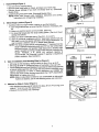
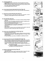
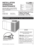
Range Overall Dimensions:
Width - 29-15/16" (76.04 cm)
Height - 35-1/2" (90.17 cm)
•Add 2" (5.08 cm) for doorhandle
Depth - 26-3/8" (70.00 cm)
_
I
_
• INSTALL
ANTI-TIP
DEVICES
• FOLLOWALL INSTALLATION
INSTRUCTIONS.
PACKEDWITH RANGE.
r" =.CTRICAL SPECIFICATIONS: 120/240 VAC OR 120/208 VAC 60 Hz 50 amp circuitprotection recommended,
,Imp minimum required. Wire size: For 50 amp service use #6 60°(3 or #8 75°C (copper only) three or four
r^_ductor, for 40 amp service use #8 (copper only) three or four conductor.
LECTRICAL CONNECTION: Unitto be properlycircuitprotected and wired accordingto local electricalcode and
,_ationalelectriccode, Unit power requirements located on serial plate on front of range.
8101P265-60
(04-97-00)
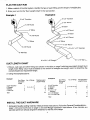
1. UnpackRange (Figure 1)
• Cut and remove shippingcarton.
• Removelowerrangepanelor drawer,and place outof work area.
• Removeblower package (if you have not already done so.) (Downdraft
ModelsOnly.)
• LocateDuctingInstructionsheet. (DowndraftModelsOnly.)
NOTE:Please read through entire installation instructions and ducting
instructions priorto beginninginstallation.
1
2. Select Range Location(Figure 2)
• Carefullyselectthe rangelocation,keepingin mindthefollowing:
A. Over-rangecabinetsarenotrecommended.However,ifnecessary,see
(Figure 1)
B. Makesure electricalpower can be provided.(See #13.)
C. For downdraft ranges plan the range ductingsystem. (Per #'s 9-12 and
ducting instructions.)
D. Make sure there is adequatespace. (See#'s 4, 5, 6, and 7.)
E. island or peninsularinstallationswith 24" deep base cabinet must use
rear toe space is desired, use 27" or deeper base cabinets.
NOTE:ThisrangecomplieswithUL requirementsfor "1"clearancefrom the
rangeto adjacentverticalsidewallsand7/8" fromrearverticalwall.
flushAbnormalsurface
back (no rear toe unitoperation(highheatand
space) cabinetsto avoid rangenoutensils)could
interference, lfa
__ _"
', --"q-',_- -'
._________L
__.._--.
L_'N.J
OVERNoT
RECOMMIENDEDRANG[
CABINET
_lscr,)1.24
(s_ ,)
25" MIN.
_63._o
¢,,)
t
..
_,
I,r_
.'
resultinpossiblescorching,of
ailsandposea
hazard. Therefore, a _, vertical
(15.24 wcm)
minimumpotential
spacingfire
is
recommended.On Downdraftmodels6" spacingis requiredfor
properventilation.(Seeillustration.)
(
(Figure2)
SLIDE-IN
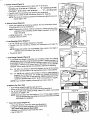
3. Type of Installation (Free-Standing/Slide-In)(Figure 3)
• Will range befree-standing?(Rangesettingonfloor.)If so, go to #7.
• Will rangebe slide-in?(Rangetop restson countertop.)If so, go to #4.
• Theseapplianceshavebeendesignedinaccordaneewiththerequirements
of varioussafetyagenciesand complywiththe maximumallowablewood
cabinet temperatures of 194°F. If these appliancesare installed with
cabinetsthat havea lowerworkingtemperaturethan194°F,discoloration,
delaminationor meltingmay occur.
NOTE:Slide-incutoutdoes notallowfor use ofbacksplashorsidepanels.
If eitherare desired,usethefree-standingcutoutand instruction.
(Figure 3)
• Moststandard countersare 25" (63.50cm) deep,36" (91.44cm) high,and
extend 1" (2.54 cm) over the cabinet front.
• Measurethe countertop and overhange.
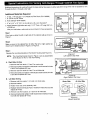
4. Measurefor Slide-InCutout (Figure 4)
_!iii
(Figure4)
5. Slide-In Cutout (Figure5)
* Use the overhang measurementto figure the "A" dimension:
Overhang 1/2" (1.27 cm) to 1" (2.54 cm) .... "A" = 22-5/8" (57,47cm)
Overhang 1" (2.54 cm) to 1-3/4" (4.45 cm) .... "A" = 23" (55.42cm)
. Carefullymarkthe countertopand recheckyour dimensions.
• Before you cut, checkthe rear countertopdimensions. (See#6.)
NOTE:The minimumclearancebetweenthe cutoutand cabinetdoors and
drawer edge is 7/8".
6. Slide-In Cutout (Figure 6)
• Check your marked up dimensionscarefully.The rear dimensions shown
in the illustrationmust be maintained.
NOTE:Wherethis isnot done,it will be necessaryto relievea portionof the
undersideof the countertop and/or support members to clear the
range rear panel.
• Cutting tolerance is = 1/'6(.16 cm.)
• Carefullymake the cutout.
(Figure5)
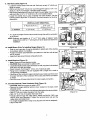
7. Free-StandingCutout (Figure 7)
• 30-1/'8" (76.52cm) minimumclearance is required.
• Carefully mark the countertop, recheck your dimensions and make the
cutout.
NOTE:Range side panels may be desirable if the cutout is too large or
(Figure 6)
• Proceedto step 8.
3or.-_.1/le,,
_, Over-RangeCabinets (Figure 8)
- To eliminate the hazard of reaching over a heated surface unit, cabinet
storage space abovethe rangeshould beavoided. If cabinet storageis to
beprovided,the riskcanbereducedby installinga rangehoodthat projects
horizontallya minimum of 5 inches beyond the bottom of the cabinets.
However,if over-rangecabinetsare necessary,observethe following:
cabinetsare on one side of the range only.
B = 30" (76.2 cm) minimum clearance between the top of the cooking
platformand the bottom of an unprotectedwood or metal cabinet.
protected by not less than 1/4" (0.635 cm) FLAME RETARDANT
B = 24"
(60,96 ore) minimumwhen
bottomof
wood or
metal
cabinet
is
millboardcovered
with not less than
No. 28MSG
sheet
steel,
0.015"
(0.038 cm) stainless steel, 0.024" (0.061 cm) aluminumor copper.
NOTE:If
you are NOT installinga downdraft unit, skip to step 13.
9. Measure
Forbe
FloorVent
• If unit will
ventedthrough the wall, go to #11.
_-"'T_'[
__.,._,._1/_
(Figure 7)
_J_______._-_.
_
_)"
_
""
I
_
T
IF
• Iffloor willbe concrete slab,see enclosedducting instructions.
• For let and right hand venting through cabinet toe space, see special
instructionson pages 7 & 8.
NOTE:Optimumcenterlinevent locationis 11"to 17" from edgeof cabinet.
Ventslocatedless thanthis distancewill requirethe unitto be raised
over blower for installation.
_
//_/_
_--
/
O O
O O
(Figure8)
_" FloorVent Cutout(Figure 10)
- Checkthe direction of the floor joists (seeillustration.)
• Locate6" square cutout anywherewithin shaded area.
The cutout must miss the floor joists!
• Recheck your dimensions and make the cutout.
• Skip to Step #12.
3
_)
_
(Figure 10)
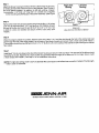
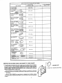
11. Wall Vent Cutout (Figure 11)
center
to center.
II
_-
_
. WALLSTUD
• Willtheventductbe6" (15.24cm) roundthroughthewall or3-1/4" x 10"
(8.26 cmx 25.4 cm) rectangle, verticatlyinside the wall?
/"
• See Ducting Instructionsfor rear duct insidethe wall. Note: Cutout in the
wall must clear 3-1/4" x 10" (8.26 cm x 25.4 cm) transition elbow.
• Locate the closest stud to your proposed vent hole location. Use the r_ (/_._
followingchartto figurethe "X" dimension.Seethe illustrationfor the other
dimensions.
oceeveasus
err.
uareusua
0 c°s
"X" MINIMUM
VERTICAL DUCT INSIDE WALL
6" Round(15.24cm)
3-1/4"x 10"
(8.26cmx 25.4cm)
4" (10.16cm)
6"(15.24cm)
. . .
(Figure 11)
THROUGH
THROUGH
OUTSIDE
WALL
THEFLOOR
12.54cm
I"
)_
• A 1" (2.54cm) lengthof duct mustprotrudethroughthe wall for connection
_-
tOthe blower.
(_
locatedfrom
9-3/8"to
11"iswill
raisedover
blowerfor
NOTE:Optimum
vent
location
11"requireunitto
to 17" frombe
edge
of cabinet.
Vents __1_]
/ j f j
installation.
"=""_._"D'U'_Th
--
_r _.-iJ
for properwire size.) If four conductorwire is used,see #15 for connection
to range,
• See frontcoverof theseinstructionsfor propersupplyconnection.
_ Jr f Jttf
n_f
IF
•
METALJOUCTDucT
TAPE I DUCT
_TAPE
12. Install Blower (Prior To Installing Range) (Figure 12)
• Refertoyourvent plan. it may be desirableto attachpart of the ducting
to theblowerbeforeit is installed.
• Positiontheblower(seeillustration)and attachitto thefloorwithat least
two (2)screws:
• Applyducttape aroundblowerexhaust/ductjoint.
,3. Install Electrical (Figure 13)
• Note: Observe all localelectricalcodes.
• CAUTION:Makesure power to cable is OFF.
• Locatetheelectricpowersupplyinthe floor orwall, anyplace inthe shaded
areawhichwill clearthe blower.
• DirectConnect.Pullthrough5' (152.4 cm)of electricalcable.
• Range Cord:Canadianunitsare equippedwitha range cord. Install a
corresponding
receptacle.
J'J_fT
/ _ _
/ _,3rf
(Figure 12)
L'IOCATEELECTRICA
_'L
POWER
IN
SHADED
AREA I
I
_
/.-_,
5 FEETOF
ELECTRICAL CABLE
_)
(Figure 13)
/ _
cup
w_s,eR
• CAUTION:Makesure
powerto
cable is OFF.
14. ConnectElectrical
(Three
ConductorWire)(Figure
14)
__o
t
•• Remove
range electrical
service cover,powercable
located on the
back, lower
Usethreethe
orfourconductor
copperstandard
(seefront
cover __,_ "-NEU'mAL(WHITE)
w____
left-handcorner.
CLAMP _
• Installa 3/4" (1.91cm) clampin the hole providedbelowthe terminalblock. ,_CABLE
• Strip 3" (7.62 cm) of outer insulationfrom the cable.
(Figure 14)
• Strip 1/2" (1.27 cm) of insulationfrom each wire,
• Pull the cable through the cable clamp. Attach the BLACK, RED, and
WHITE wires (see illustration.) Tighten the terminal block nuts and the
cable clamp and install cover.
• On ranges equippedwith a range cord, plug the cord into its receptacle.
• Skipto Step #16.
15. ConnectElectrical (Four ConductorWire) (Figure 15)
• Remove the range electrical service cover, located on the back, lower
_ ;'_
left-hand corner.
• Removethe grounstrapscrewand bendthe strapup as shown.Installa 3/4"
(1.91 cm) cable clampin the hole provided,below the terminal block.
I,_NO
l
• Strip 3" (7.62 cm) of outer insulationfrom the cable.
, GROUND
• Strip 1/2" (1,27 cm) of insulationfrom each wire.
WIRE
• Pull the cable through the cable clamp.
• Make a loop in the bare groundwire and attachitto the rangewith the screw
"BASe
that held the ground strap,
_. _'OROUNC)wlSE
• Attach the BLACK, RED, and WHITE wires (see #14.) Tightenthe terminal
block nuts and the cable clamp.
(Figure 15)
• Tape the ground strap to the WHITE wire as shown. Install electricalcover.
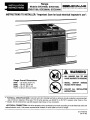
16. Install Options (Figure 16)
• If the backsplash or side panels are to be used, install according to
instructionsincluded in those accessories.
c oo.
a esure
oa.e ower
17. Position Range (Figure 17)
• Free-Standing,Adjust the rangefeet so the rangeand cabinetheightwill be
approximately the same. Slide the range into place, taking care not to
damagefloor covering.
• Slide-In. Adjust range feet so that range top clears countertop. Slide/lift
range into place. Adjust feet so range is adjacentto countertop surface.
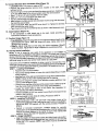
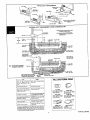
18, Anti-Tip DeviceInstallation
NOTE: A risk of range tip over exists if the appliance is not installed in
accordancewith the installationinstructions provided.The proper use of these
devices minimizesthe risk of TIP-OVER.In using these devices the consumer
must stillobservesafety precautionsas statedin the USE and CARE MANUAL
and avoid using the oven door and/or lower drawer as a step stool.
Instructionsare providedfor installation in eithera wood or concretefloor.Any
othertype ofconstructionmay requirespecialinstallationtechniquesas deemed
necessaryto provide adequatefastening of the ANTI-TIP bracket to the floor.
STEP 1 - LocatingThe Brackets
• Placethe unitin itsfinal location.
• Removethe storagedrawer or lower door panel(dependingon model
beinginstalled.)
• Markthe floor at the right and leftwherethe rangefront meetsthe floor.
NOTE: Protectthe floor with maskingtape prior to marking.
• Removethe range for access to the bracket mountingpositions. Use
care to avoid damageto floor.
• Drawa lineon the floor at the backof the cutoutwhich isoffset 23-5/16"
from the marks made at the front of the range (see illustration.)
• Locate the center (side to side) of the cutout. See illustration for
free-standingand slide-in dimensions.
•
Positionbrackets 13-7/8" from center line and flush to the backline as
shown in the illustration.
• Use the bracketto mark holes for drilling. Proceedto STEP 2.
STEP2 - InstallingThe Brackets
markedhole positions(a nailor awlmay beusedif a drilJisnotavailable.)
• Wood
a I/8" with
pilotthe
holescrews
in the center
of each
of the
SecureConstruction:Drill
the ANTI-TIP brackets
provided.
Proceed
to
STEP3.
• Cement or Concrete Construction: Suitable screws for concrete
constructioncan beobtainedat a hardwarestore.Drillthe requiredsize
hole for the screw obtained in the center of each of the marked hole
positions.Secure the ANTI-TIPbracketsto the floor,
STEP3Rangerange
Installation
• Alignthe
to its designatedlocationand slideit back into position.
Make surethat the rearleveling feet arefully insertedinto and secured
by the ANTI-TIP brackets. NOTE: Leg levelers must be screwed out
1-1/2 turns.
5
-. J'
" 1" /
4
I
(Figure 16)
(Figure 17)
_1
,5,1
_1
_
[59.21
cm]
2_5/16
TYP
=
_'F.o._0RAw_
0_L'NES.AN_EAT
I
I (_6S2
.A-_L.
F"_E-STAN0_
2g 7/8=,)
SL_E-_N 1(75.8s
_01/_"
_)
(_8"2_'=.>
[5 _/_6"
(379_
_s/_S.m)
_1 II
(Figure 18)
_._,-e._v_.ms
_
__/_.
___._"
.._OKEr
-
19. Level Range (Figure 19)
• Free-Standing.Adjustthelevelerfeet to levelrangewiththe countertop.
• Slide.ln.Adjustthelevelerfeettotakesomeoftheweightoffefthecountertop.
• Unit must be level for optimum baking performance. Check levelness inside
oven using a level that is placed on oven rack.
• Fornon-downdraft unitsgo to step 22.
--IL
ll
(Figure 19)
20. Connect Blower Electrical (Downdraft Units Only) (Figure 20)
,ow_,co,o
BLOWER
• Connectthe blower power cord on the range to the blower (see illustration.)
_]__
21. Install Flex Duct (Downdraft Units Only) (Figure 21)
• Attach the flex duct to the blower and range (see illustration.) Using a
screwdriver,securelytighten duct clamp at each connection.
22. CheckOperation (Figure22)
• Unpack and install grill elementin one side and optional cookingcartridge in
other side.
• Be sure to remove all packaging materialsfrom unit priorto applying power.
• Switchthe electricalcircuit breaker to the ON position.
• Consult Use & Care Manualfor operation.
• Checkrangetop elements.Fancomeson automaticallywhen grill is turnedon,
• Check
oven.C°°kingcheck
ventCartridgefan,
doesnot energize fan automatically.
]lJ
iolli i
I
(Figure 20)
_! _,f
_k,_
(Figure21)
C.ECK .EAT pOWE,
O,
__A,,
there are no air leaks. Verify proper airflow with airflow card.
• With vent fan on, check all vent duct connectionsto the outside to make sure
23. Install Lower Left and Right Side Toe Plates (Figure 23)
• Pull protectivebackingfrom tape.
• Set Sideplate on floor guide plate between cabinet and range until plate is
positioned over the side trim. Press plate againstside trim on range to insure
tape has bonded.
• For Non-Downdraftunits, finish your installationby replacingthe drawer.
24. Install AccessPanel and LowerAdjustable Panel (Figure 24)
• After checking for air leaks at duct connections,install the lower range door.
• Measurethe distancebetweenthe lower panelclipand the floor.Dimension"A".
• Cut covemolding (providedon some units- see Note2) to this Dimension"A".
• Insertcove molding (or other selected material) into lower panel clip.
NOTE: 1) It will be easierto attachthe cove molding if the access door is
removed from the range.
2) To matchyour installation,variouscolors of cove moldingmay be
purchasedfrom any building supply store,
25. Install Jars (Downdraft Units Only) (Figure 25)
• Openaccess panel.
• Placedrain jars intotheir holders located behindthe front legs of the range.
ROLS
__"
(Figure 22)
..,,, _
_.._--_
(Figure 23)
i _,._S::._
(Figure24)
NOTE:On units with one side grilling, only one drain jar is supplied.
(Figure25)
6
:
'
_peCial
Instructi---onsFor Ven_net
Toe S )ace
Additional instructionsfor ventingthrough the base cabinettoe space oneither sideof the rangewhen it is not possibleto vent
through the floor or through a rear wall.
Additional MaterialsRequired
1.5" Dia. x 19" long (12.7 cm x 48.26 cm) Flex Duct* (P/N702935)
1 • 6" (15.24 cm) 90° Elbow
2. Hose Clamps* (P/N702331)
Left
Cabinet
1 5" to 3-1/4" x 10" (12.7 cm to 8.26 cmx 25.4 cm) Transition*
•
2. Wood Spacers (right sidevent only) 1-1/2" Thick x 9" Long (3.81 cm
5._o' I (_'_ cm)
Dis-Hole
|
X 22.86cm)
*Seeyourlocaldealerorauthorizedservicecontractorfortheseaccessories.
_
31.19"
79.22
_
!
_-17.12S",-_
(,3.,7._.
=']-.C-"-_-----"--"//
--
Step 1
Cut a hole in either the left or right side of the cabinet wall as shown in
Figure 1.
Make a cutout in the cabinet floor of either the left or right cabinet as
Step 3
_elocatethe mountng bracketson the blowerhousing(see Figure4.)
(43.49
_) I 5.so'
| Dis.
Hole
'
. _..9, or,,
---------_'---_r // =
(Figure 1)
"h
t=7
. ===.J==_
_r__
J,.
.---t.I'_'_(e=.7_m)= ! _o_OT_o"N
(Figure 2)
Left Cabinet (TopView)
NOTE: The mountingbracket shown in Figure 4 are as asssembled
at the factory for flooror rear wall venting.
A. RightSide Venting
_-17.125"-,_
'_
Step
2
shown by the shaded areas in Figure 2 or Figure 3.
"
Right
Cabinet
..¢
iNu='-rltd.
_
14.
2. Removebracketandreattachitwithstuds 1and 2 insertedin holes
A and C and replaceall 3 nuts.
3. Remove nuts from studs 5, 6 and 7 on air inlet side•
4. Removebracketandreattachitwithstuds5and6insertedinholes
D and B and replaceall 3 nuts.
11"
=
s,owe, I,OCt'nON
(_o=_7"-m)----'_
(Figure 3)
B. Left SideVenting
1. Remove nutsfrom studs 1,2, 3 and 4 on motorside.
2. Removebracket.
4. Reattachbracketwith studs 4 and 1 inserted in holes A and C and
replace all 4 nuts.
5. Removenuts from studs 5, 6, 7 and 8 on air inlet side.
6. Removebracketand reattachitwith studs8 and 5 insertedinholes
D and B and replaceall 4 nuts.
Right Cabinet (TopView)
Motor Side
Air Inlet Side
....
Mounting
srecket
(Figure 4)
BlowerAssembly
Step 4
Attachthe blowerhousingto the floor withthe outlettoward the direction
of venting and the inlettoward the front of the cabinets. (See Figures 2
and 3 for specific location.) in addition, for left side venting, a spacer
Right Side
Venting
Left Side
Venting
I
I
{erthe mountingbracketflanges ofthe blowerassembly.(SeeFigure
Step 5
_,_proximately1-1/2"
thick x 9" long (3.81 cm x 22.86 cm)is required
Removethe inside wire and the outside stringfrom the first 1-1/2 inches
(3.81 cm) of one end of the 5" (12.7 cm) flex duct (P/N702935.)Stretch
this end of the flex duct over the end of the 5" to 3-1/4" x 10" (12.7 cm
to 8.26 cm x 25.4 cm) transitionand secure it with a hose clamp (P/N
702331.)
__
Spacer/
(Figure 5)
Viewfrom Air Inlet Side of Blower
Step 6
Whenthe range is placedinto position,feed the open end of the 5" (12.7 cm)flex duct through the hole in the cabinet side wall
and through the side of the range, attach it to the outlet of the blower housingand secureit with a hose clamp (P/N 702331.)
Thetransitionshouldthen beattachedtothe 3-1/4"x 10" (8.26cmx 25.4cm) ductingin the cabinettoe spacethrough the cabinet
floor cutout.
Step 7
Installthe 6" (_5.24cm) elbowto the inlet of the btowerhousingand secureit with duct tape. The open end of the elbow should
be pointed to the left. Attach the 6" (15.24cm) flex duct (provided with the range)to the elbowand to the range. Secure it with
2 hose clamps (P/N 702331.) See Step 21 of the installationinstructions.
NOTE:Forrightsideventing,the 6" (15.24cm)diameterflex duct may becutinhalfand useone sectioninsteadof the full length.
"- make it easier to assemble.
'JENN-AIR
403WEST
FOURTH
STREET,
NORTH
• NEWTON,
IA 50208
I
.
DUCTING
INSTALLATION
INSTRUCTIONS
FREE-STANDING
SLIDE-INMODELS
GRILL-RANGE
DROP-IN
c o M _= A N Y
E N N-AI
3o3_S.ADEL*ND• ,NO,_NAPOL'S,
'N46226oR
9ol
k
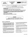
DUCTING MUST CONFORM TO LOCAL CODE MATERIALS AND "MAKE-UP"
300 CFM MINIMUM
IMPORTANT: SAVE FOR LOCAL ELECTRICAL INSPECTOR'S
• DUCTING A JENN-AIR GRILL-RANGE
PERFORMANCE.
IS EASY BUT CRITICAL
• AFTER READING THESE INSTRUCTIONS
REQUIREMENTS-USE
FOR PROPER
PLAN THE DUCT RUN.
• USE THE 'DUCT LENGTH CHART' TO FIND THE EQUIVALENT
LENGTH OF THE RUN.
• SHIFTTHE BLOWER TO 'HIGH RANGE' IF INDICATED (DONE BY SNAPPING
'RESTRICTER RING' OUT OF THE BLOWER INLET), BE SURE BLOWER IS
NOT RUNNING.
THE
• INSTALL THE DUCT HARDWARE.
• ENJOY GRILLING
AND COOKING
AT ITS FINEST!
THIS UNIT IS RATED AT 60 FEET OF STRAIGHT DUCT
LOW RANGE IS UP TO 30 FEET--HIGH
IMPORTANT
GENERAL
RANGE IS 31 TO 60 FEE'[
CONSIDERATIONS:
1. Use 6" diameter round or 37/4"x 10"rectangular only,
except as follows: For Electric Models, 5" diameter
round May be used for venting straight out the back of
the rangeand directlythrough the wallfor 10feetor less.
For Gas Models with Electric Ovens, 5" diameter
roundMust be usedif the duct lengthis 10feet or less.
5. The numberofdownstreamelbowsor transitionsshould
belimitedto three.The initial 5"to 6"straighttransition,if
used,neednot becounted in this number.
6. Handmadecrimpsare likelyto cause restrictions.
7. If an alternate wall or roof cap is used, be certain duct
sizeis not reduced,andthat there is a backdraftdamper.
It is best to use listed caps to be certain of proper
performance.
2. Do not use 5"elbowsexceptin a 5"system.Instead,use
a 5"to 6"transitionfollowedby a 6" elbow,or a 5"to 31/4
,,
x 10"elbowtransition,
3. Usequalitymetalduct of at least26gaugegalvanizedor
24gauge aluminum.Inferiorqualitypipeand fittingscan
cause up to twice the restriction shown and is a poor
value. See box on page 4 for optionalunder-slabducting. Local codes may require a heaviergauge material
or restrictPVC.
8. Thermalbreaks:Inareasofextremecoldweather,it may
be necessary to provide a short length of nonmetallic
duct as closeto the wall as possible,to preventconductJonalong the metaJduct.
9. High altitude installations: It is advisable to reduce
allowableduct run by 20%.
4. Distance betweenadjacent fittings (elbows,transitions,
etc.) shouldbe at least 18".Thefarther the better.Closer
distancepromotesturbulencewhich reducesairflow,
10. Followthe duct calculation on page 2 carefullyfor best
performanceand satisfaction.
1
PART NO. 204754D
PLAN THE DUCT RUN
1. Make a sketch of the total system. Identify the type of each fitting and the length of straight pipe.
2. Enter your run into the 'Duct Length Chart' in the next section.
Example I
__
Example 2
_.5"
to 6" Transition
to 6" Transition
2' of 6" ound
Elbow
2' of 6" Round
'
\ .6'
Elbow
4' of 6" Round
\
6"Round
Elbow
6"
)_"
6" Elbow
;"Elbow
4' of 6" Round
.
6 of 6 Round
31/4
" X10"Transition
6" WallCap
10'of 3¼"x 10"Straig
C,..,.
DUCT LENGTH CHART
1. Elbows, wall caps and other fittings are shown in the table on page 3 with their equivalent straight duct
length. Each fitting value must be added to the amount of straight duct length used, to determine the
overal! straight duct equivalent length.
2. Using the examples above:
ExampleI
Example2
DuctFitting No.ofFittings TotalEquivalent
Equivalent
Length-Fittings
Length
5"to6"Transition
1
1
1
6"Straight
"f 2+4+6= 12
12
6"Elbow
5
2
10
6"WallCap
0
1
0
DuctFitting
No.ofFittings TotalEquivalent
Equivalent
Length-Fittings
Length
5"to6"Transition
1
1
1
6"Straight
t 2+4+6+4= 16
"t6
6"Elbow
5
3
15
6"to31/:_
' x10"
Transition
1
1
1
31/4,
x10,Straight
1
10
10
31/4"
x 10"WallCap
0
1
0
Total
43
Total
23
INSTALL THE DUCT HARDWARE
1. Using good quality ducting material, install per these instructions. Follow the General Considerations
page 1, Do's and Don'ts box on page 4, and Grill-Range Installation Instructions. A few minutes an£1
pennies spent now will pay long term dividends for the life of the range.
2
USE TABLE BELOW TO CALCULATE TOTAL SYSTEM
DUCT F|TTING
EQUIVALENT LENGTH
DUCT FITTING
6" Dia. 90 ° Elbow
5 FL (1.52 m)
6" Dia. 45 ° Elbow
2.5 Ft. (.76 m)
5" to 6" Transilion
NO. OF FITTINGS
TOTAL EQUIVALENT
LENGTH-FITTING
.._
P/N A456
_m n.ow THZS
omECT_0N
o27c= to _24 cm}
_ _OT _
RECOI_Eta_tD
AIRFLQW
1.0 Ft. (,30 rn)
6" tO3%" x 10 " 90_ Elbow
(1524 c rn tO 8 25 cm X 254 cm)
WN A496
5 Ft. (1.52 m)
AIR F1-OW
3%" X 10 " to 6" 90" ELBOW
{8 26-cm • 254 cm to 1524 Crn)
P/N A496
9 Ft. (2.75 m)
AIR FLOW
6" to 3V,'*x 10" Ttansitton
_._"_
(1524 Ctn to 826 cm x 254 cm}
P/N A463
1 Ft. (.30 m)
(Also PiN A453 _nS_de O_¢t)
AIR F'LOW
3%" x 10" to 6" TransilJ_l
(82Scmx254cmto15.24
cm)
WN A463
../_
4.5 Ft. (1.37 m)
AIR FLOW
5" to 3%" x 10" 90° E_¢ N /_.,_
[12,7 cm to 8,26 cm X 25.4 cm)
P/N A4g5
AmRow T,_s
DIREC*_
NOT
REOOMI4EN[_
6 Ft. (1.83 m)
AERF].O_
3,1,"x 10" 90° Elbow
is.2s¢,_x _.4 cm)
_
5 Ft. (1.52 m)
3%" X 10" Flat Elbow
(3.66 rn)
[8:26cmx2s4cml
_
12 Ft.
6" Wall Cap 5" Wall Cap m,_
(15.24 crn)
(12.7 ¢m)
P/N A406
PIN A405
(Short Run)
0 Ft. (0 m)
3%" • 10" Wall Cap
_s26cmx2s.4cm_
WN A4D3
0 Ft. (0 m)
10" • 10" Roof ,lack
USE LEIGH PRODUCTS
P/N
5850
(Z5
4 °q
x 25'4 cm_
0 Ft. ((] m)
IAblO mmt4Hle R J_nn-AIr p/N ?01943)
5" P/N 708786
6" P/N 715557
THERMALBREAK
6" DIAMETER
STRAIGHTDUCT- FEET
3V," x 10"
STRAIGHTDUCT. FEET
2 Ft. (.61 m)
(For flex duct,
multiplyby 2)
1 Ft. 1.30 rn)
1 Ft. (.30 m)
SYSTEMTOTAL
1. This grill-range isequippedwith a dual rangeblower.It is shippedfromthe factory
mostinstallations.
If theRANGE'
EquivalentDuct
Lengthexceeds
SHIFTINGin
LOW RANGEfor
THE BLOWER
FROM 'LOW
TO 'HIGH
RANGE'
30 feet it must be shifted to HIGH RANGE. Do not shift to high range for
1. BLOWEROFF
_
_
J_,,,'11
affect the flame pattern on gas units.
In the examples on the precedingpage, the blower in example #1 shouldbe
installed
shiffed_igh
Range,
as received from the factory.The blower jnexample #2 should be
,_
.o shift to HIGH RANGE, be sure blower is stopped and carefully remove
the spring loaded "RESTRICTERRING'out of the blower inlet. See illustration
at fight. lengths.This will cause excessivenoise, conditionedair loss and
shorter
_
3
2. SNAP OUT RESTRICTERRING
' s"ola.su=t
TYPICALDUCT ARRANGEMENTS
Typical througft
Rein" DUCt
(Outside Waft)
Through Cabinet Toe Space
(See special instructions
204917)
(|l_.side Wall)
OPTIONAL DUCT ARRANGEMENT UNDER CONCRETE SLAB
NOTE; PVC sewer pipe Wpe PSM 12454-S
Also Required: Jenn-AW Kit P/N 712139,
Ilvaileble trom your authorized set-
t
Sewer Pipe
Coupling
Sewer Pipe Elbow
Sewer Pipe Elbow
Pack tightly with
gravel or =rand
completely around pipe,
Note:
Window
WeB installation
for electric models only.
I
12" Min,
_
* Cut Off Pipe at
!
Wall Cup -
Sewer Pipe
Sewer Pipe Elbow
Sell the space between outside of
wall ¢mp inlet and inside of PYC 6" Dla. PVC
couf_kl g wit_ ¢au_blg m_te_L
Couplleg
oo
Pack tightly "t_th
gravel or sand
completely around pipe.
oo.'r
WALL
CAPS/THERMAL
BREAKS
use 5" 112.7 cm), 6" (15,24 cm),
Use 4" (1016 ore) dryer vent pipe
or 3_/," x 10" (8,255 cm x 254 cm),
or flex duct,*
piPe as recommended for your !
Use rec<;mmende_Wallcap_
model.
UsenomomthanOneg0°e_owwim
five inch (1P.7 ore) duct _r th r_._g0*
eLb0ws
wilh
sixinch(15.2cm)or3"x 10"
(8255 crn x25 4ore) _u_
Use launary type wall Cap.
Over run your systenn with too
marly b_rtd$aridtu_$.
Pad 708786
Fits 5" (t 2.7 cm) Round
Duct. Acids 2 ft. to duct
length CalCulation.
Dum systemto the 0uts,:le
Vecltinto art atticor ¢r_wlspace,walls
and conc_lled spaceofa building.
Mix 6" (15.24¢m) duct ar',d3'/," x10"
duct (8.255 cm x 25A cm) within the
samesystem rf necessary
Recluceback to 5" {12 7 cm) system
atterusieg 6" (15.24 cm)or 3V," x 1G*'
(8.255 cm x 25.4 cmt.
Tape all joints securely
severalwraps of fade.
Butt joints, atways use male-female
Connectiorl$_ndirectronof flow.
0se one unit per duct system.
witi_
_
PART _15557
PitsS"(15._
ore)Round
Duct. Adds 2 ft. to duct
length calculation
_
(_
MODEL ._.d$
Pits 5" (127 cm) Round
Duct. R_uire_ 5%" (13.34
cm) Dia opening.
MOD_tL
Fits 6" t15.24 cm) Round
Duct, Requires6%" (15.875
cm) 0ia. opening,
f_
Exhaust mote than one unit into a
sJn21esyst(_n
MODEL A44_
Single-darrtper,
down
diScftargetofit3%'xlO"
{E.25_cm x 25.4 cm) duct.
"Althougrt riot recommended,5" Or 6'* metal flex duct may be LISe_.Due to
_eltregu/arsutfac_°tf_exib_e_'uct_'_'eacrtfc_off!exduCtc°unfaastw°l_l
feet of regular metal _uct. Also, each elbow made in flex _luct wc_JIdcount
twice as muct_ asstandard metat el_ow. The 0est idea with ftexible ducting
is tOkeePit as ellorl and as _t_'_ightas _ossi_e.
4
LEIGH PRODUCTS
P/N 5950
RoofJacktO'xt(_"
(254 crn x 254 cm)
PART NO. 204754D