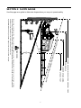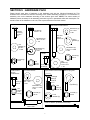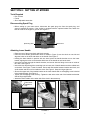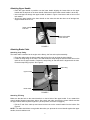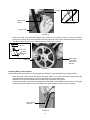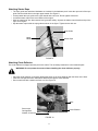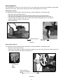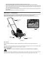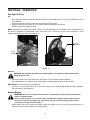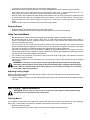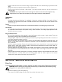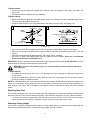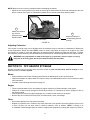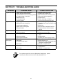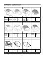
1
OPERATOR’S MANUAL
20” Side Discharge
High Wheel Mower
570 Series
IMPORTANT: READ SAFETY RULES AND INSTRUCTIONS CAREFULLY
Warning: This unit is equipped with an internal combustion engine and should not be used on or near any unimproved forestcovered, brush-covered or grass-covered land unless the engine’s exhaust system is equipped with a spark arrester meeting
applicable local or state laws (if any). If a spark arrester is used, it should be maintained in effective working order by the operator.
In the State of California the above is required by law (Section 4442 of the California Public Resources Code). Other states may have
similar laws. Federal laws apply on federal lands. A spark arrester for the muffler is available through your nearest engine authorized
service dealer or contact the service department, P.O. Box 368022 Cleveland, Ohio 44136-9722.
MTD PRODUCTS INC. P.O. BOX 368022 CLEVELAND, OHIO 44136-9722
PRINTED IN U.S.A.
FORM NO. 770-1044A
(1/98)
Table of Contents
Content
Page
Safe Operation Practices .........................................................................3
Slope Guage ............................................................................................5
Finding Model Number.............................................................................6
Unpacking ................................................................................................6
Hardware Pack ........................................................................................7
Setting Up Mower ....................................................................................8
Controls....................................................................................................13
Operation .................................................................................................14
Maintenance ............................................................................................15
Service & Adjustments............................................................................ 16
Off-Season Storage ................................................................................ 17
Trouble-Shooting Guide.......................................................................... 19
Your Notes .............................................................................................. 20
Shroud Chart............................................................................................21
Parts List ..................................................................................................22
Warranty ..................................................................................................24
2
SECTION 1: IMPORTANT SAFE OPERATION PRACTICES
This symbol points out important safety instructions which, if not followed, could endanger the
personal safety and/or property of yourself and others. Read and follow all instructions in this manual
before attempting to operate your lawn mower. Failure to comply with these instructions may result
in personal injury. When you see this symbol—heed its warning.
Your lawn mower was built to be operated according to the rules for safe operation in this manual.
DANGER: As with any type of power equipment, carelessness or error on the part of the operator can result in
serious injury. If the operator violates any of these rules, he/she may cause serious injury to
himself/herself or others.
1.
GENERAL OPERATION
• Read this owner’s guide carefully in its entirety
before attempting to assemble this machine. Read,
understand, and follow all instructions on the
machine and in the manual(s) before operation. Be
completely familiar with the controls and the
proper use of this machine before operating it.
Keep this manual in a safe place for future and
regular reference and for ordering replacement
parts.
• Your rotary mower is a precision piece of power
equipment, not a plaything. Therefore, exercise
extreme caution at all times. Your unit has been
designed to perform one job: to mow grass. Do not
use it for any other purpose.
• Never allow children under 14 years old to operate
a power mower. Children 14 years old and over
should only operate mower under close parental
supervision. Only responsible individuals who are
familiar with these rules of safe operation should be
allowed to use your mower.
• Keep the area of operation clear of all persons,
particularly small children and pets. Stop engine
when they are in the vicinity of your mower to help
prevent blade contact or thrown object injury.
Although the area of operation should be
completely cleared of foreign objects, an object
may have been overlooked and could be
accidentally thrown by the mower in any direction
and cause serious personal injury to the operator or
any others allowed in the area.
• Thoroughly inspect the area where the equipment
is to be used. Remove all stones, sticks, wire,
bones, toys and other foreign objects which could
be picked up and thrown by the mower in any
direction and cause serious personal injury to the
operator or any others allowed in the area. Plan
your mowing pattern to avoid discharge of material
toward roads, sidewalks, bystanders and the like.
To help avoid a thrown object’s injury, keep
children, bystanders and helpers at least 75 feet
from the mower while it is in operation.
• Always wear safety glasses or safety goggles
during operation or while performing an adjustment
or repair, to protect eyes from foreign objects that
may be thrown from the machine in any direction.
• Wear sturdy, rough-soled work shoes and closefitting slacks and shirts. Shirts and pants that cover
the arms and legs and steel-toed shoes are
recommended. Do not wear loose fitting clothes or
jewelry. They can be caught in moving parts. Never
operate a unit in bare feet, sandals, or sneakers.
• Do not put hands or feet near or under rotating
parts. Keep clear of discharge opening at all times
as the rotating blade can cause injury.
• Many injuries occur as a result of the mower being
pulled over the foot during a fall. Do not hang on to
•
•
•
•
•
•
•
•
•
•
•
•
•
•
•
2.
the mower if you are falling; release the handle
immediately.
Never pull the mower toward you while you are
walking. If you must back the mower away from a
wall or obstruction first look down and behind, and
then follow these steps:
Step back from the mower to fully extend your
arms.
Be sure you are well balanced with sure footing.
Pull the mower back slowly, no more than half way
toward you.
Repeat these steps as needed.
Do not operate the mower while under the
influence of alcohol or drugs.
The blade control handle is a safety device. Never
attempt to bypass its operation. Doing so makes
the safety device inoperative and may result in
personal injury through contact with the rotating
blade. The blade control handle must operate
easily in both directions and automatically return to
the disengaged position when released.
Never operate the mower in wet grass. Always be
sure of your footing. A slip and fall can cause
serious personal injury. Keep a firm hold on the
handle and walk, never run. Mow only in daylight or
in good artificial light.
Stop the blade when crossing gravel drives, walks
or roads.
If the equipment should start to vibrate abnormally,
stop the engine and check immediately for the
cause. Vibration is generally a warning of trouble.
Shut the engine off and wait until the blade comes
to a complete stop before removing the grass
catcher or unclogging the chute. The cutting blade
continues to rotate for a few seconds after the
engine is shut off. Never place any part of the body
in the blade area until you are sure the blade has
stopped rotating.
Never operate mower without proper guards, grass
catcher, plates or other safety protective devices in
place.
Muffler and engine become hot and can cause a
burn. Do not touch.
Only use accessories approved for this machine
by the manufacturer. Read, understand, and follow
all instructions provided with the approved
accessory.
If situations occur which are not covered in this
manual, use care and good judgment. Contact your
dealer for assistance.
SLOPE OPERATION
For your safety, use the slope gauge included as part of this
manual to measure slopes before operating this unit on a
sloped or hilly area. If the slope is greater than 15 degrees
as shown on the slope gauge, do not operate this
3
DO:
• Keep all nuts, bolts, and screws tight to be sure the
equipment is in safe working condition.
• Never tamper with safety devices. Check their
proper operation regularly.
• After striking a foreign object, stop the engine,
remove the wire from the spark plug, and
thoroughly inspect the mower for any damage.
Repair the damage before starting and operating
the mower.
• Never attempt to make a wheel or cutting height
adjustment while the engine is running.
• Grass catcher components are subject to wear,
damage and deterioration, which could expose
moving parts or allow objects to be thrown. For
safety protection, frequently check components and
replace with manufacturer’s recommended parts,
when necessary.
• Mower blades are sharp and can cut. Wrap the
blade(s) or wear gloves, and use extra caution
when servicing them.
• Do not change the engine governor setting or
overspeed the engine. Excessive engine speeds
are dangerous.
• Mow across the face of slopes; never up and down.
Exercise extreme caution when changing direction
on slopes.
• Watch for holes, ruts, hidden objects, or bumps.
Tall grass can hide obstacles.
• Always be sure of your footing. A slip and fall can
cause serious personal injury. If you feel you are
losing your balance release the blade control
handle immediately and the blade will stop in less
than 3 seconds.
DO NOT:
• Do not mow near drop-offs, ditches or
embankments. The operator could lose footing or
balance.
• Do not mow slopes greater than 15 degrees as
shown on the slope gauge.
• Do not mow on wet grass. Reduced footing could
cause slipping.
3.
CHILDREN
Tragic accidents can occur if the operator is not alert to the
presence of children. Children are often attracted to the
mower and the mowing activity. Never assume that children
will remain where you last saw them.
• Keep children out of the mowing area and under
the watchful care of a responsible adult other than
the operator.
• Be alert and turn mower off if a child enters the
area.
• Before and while moving backwards, look behind
and down for small children.
• Never allow children under age 14 to operate the
mower.
• Use extreme care when approaching blind corners,
shrubs, trees, or other objects that may obscure
your vision of a child or hazard.
4.
WARNING: The engine exhaust from this
product contains chemicals known to
the State of California to cause cancer,
birth defects or other reproductive harm.
5. Your Responsibility
• Restrict the use of this power machine to persons
who read, understand and follow the warnings and
instructions in this manual and on the machine.
• Following are representations of the safety labels
on your lawn mower. Maintain safety while
operating the mower.
SERVICE
• Use extreme care in handling gasoline and other
fuels. They are extremely flammable and the
vapors are explosive.
• Use only an approved gasoline container.
• Never remove gas cap or add fuel while the engine
is running. Allow engine to cool at least two
minutes before refueling.
• Replace gasoline cap securely and wipe off any
spilled gasoline before starting the engine as it may
cause a fire or explosion.
• Extinguish all cigarettes, cigars, pipes and other
sources of ignition.
• Never refuel machine indoors because flammable
vapors will accumulate in the area.
• Never store the machine or fuel container inside
where there is an open flame or spark such as a
gas water heater, space heater, or furnace.
• Never run an engine inside a closed area.
• To reduce fire hazard, keep mower free of grass,
leaves, or other debris build-up. Clean up oil or fuel
spillage. Allow mower to cool at least 5 minutes
before storing.
• Before cleaning, repairing, or inspecting, make
certain the blade and all moving parts have
stopped. Disconnect the spark plug wire, and keep
the wire away from the spark plug to prevent
accidental starting.
• Check the blade and engine mounting bolts at
frequent intervals for proper tightness. Also,
visually inspect blade for damage (e.g., bent,
cracked). Replace with blade which meets original
equipment specifications.
4
SECTION 2: SLOPE GAUGE
Use this page as a guide to determine slopes where you may not operate safely.
FOL
D
O
N DO
RE
PRE
S
E
NTIN
G
A1 o
5
SLO
PE
OR A FENCE POST
A CORNER OF A BUILDING
A POWER POLE
SIGHT AND HOLD THIS LEVEL WITH A VERTICAL TREE
T
T
E
D LI
NE,
15o
WARNING
Do not mow on inclines with a slope in excess of 15 degrees (a rise of approximately 2-1/2 feet every 10 feet). A riding
mower could overturn and cause serious injury. If operating a walk-behind mower on such a slope, it is extremely difficult to
maintain your footing and you could slip, resulting in serious injury.
Operate RIDING mowers up and down slopes, never across the face of slopes.
5
SECTION 3: FINDING MODEL NUMBER
This owner’s guide is an important part of your new Yard-Machine lawn mower. It will help you to
assemble, prepare and maintain your mower. Please read and understand what it says.
Before you start assembling the mower for its first use, please locate its model plate and copy the
information on to this owner’s guide. The information on the model plate is very important if you need
help from your nearest service center or the Yard-Machine customer support department.
• Every mower has a model plate. You can locate it by standing behind the unit in the operating
position and looking down at the cutting deck.
• The model plate will look like Figure 1.
This is where mower model number will be.
XXX-X-XXX-X-XXX XXXXXXXXXXX
This is where mower serial number will be.
Copy the model number here:
MTD PRODUCTS INC
Copy the serial number here:
CLEVELAND, OHIO 44136
FIGURE 1
SECTION 4: UNPACKING
Removing Unit From Carton
•
•
•
•
Remove staples, break glue on top flaps, or cut tape at carton end and peel along top flap to open
carton.
Remove loose parts included with the unit. A list of loose parts is given below. It is recommended that
you compare this list with the loose parts included in the carton and identify each part before starting to
assemble the unit.
Cut along dotted lines and lay carton down flat. Remove packing material.
Roll or slide unit out of carton. Check carton thoroughly for loose parts. Make sure that no part is
missing.
NOTE: Make sure not to crimp the cables while removing the loose parts or the entire unit from the carton.
NOTE: Reference to right or left hand side of the mower and/or front or behind the mower is observed from
the operating position.
Loose Parts
1. Upper handle
2. Lower handle
3. Hardware pack (See following page for an illustrated list of the hardware pack.)
4. Rear hi-wheel
5. Front wheel
NOTE: Remember that all hardware necessary for assembling the mower is contained in the
hardware pack, and is identified in the following section.
6
SECTION 5: HARDWARE PACK
Please identify each piece of hardware in the hardware pack with the following illustrated list. This
illustrated list is divided into sections according to the mower assembly procedure. For convenience in
assembly, sort out the hardware according to the sections given here. NOTE: The actual number of
hardware pieces necessary for an assembly procedure is given in parenthesis after each description. For
actual location of the hardware on the unit, refer to parts list at the end of this manual.
Chute to deck:
Handle bracket to deck:
Rear wheel to handle bracket:
Bell Washer (2)
.401 x .870
x .063
Hex Bolt (2)
3/8-16 x .75
Carriage
Screw (2)
1/4-20 x
1.0
Flat Washer (2)
.385 x 1.0 OD
x .135
Flat
Washer (2)
.28 ID x
.74 OD
Rear Axle
Bolt (2)
.500 x 2.62
Spring
Washer (2)
Bell Washer (2)
.39 ID x 1.13 OD
x .062
Bell Washer (2)
.401 x .870
x .063
Handle bracket
to handle:
Hex Nut (2)
3/8-16
Lock Nut (2)
1/4-20
Handle bracket
through
handle & deck:
Hex
Screw (4)
5/16-18
Hex
Flange
Lock
Nut (4)
Hex
Nut (2)
3/8-16
Flat
Washer (2)
.510 x 1.373
x .04
Self-Tapping
Screw (2)
Front wheel to deck:
Upper handle to lower handle:
Starter rope guide:
Carriage
Bolt (2)
5/16-18
x 1.5
Bell Washer (2)
.401 x .870
x .063
Bell Washer (2)
.39 ID x 1.13 OD
x .062
Hex
Nut (2)
5/16-18
Hex Nut (2)
3/8-16
Lock
washer (2)
Eye Bolt (1)
Lock Nut (1)
1/4-20
Cable to handle: (illustrated in half size)
Front axle bolt (2)
.498 x 1.635
Cable tie (1)
7
SECTION 6: SETTING UP MOWER
Tools Required
• Pair of Pliers
• Funnel
• Set of adjustable wrenches
Disconnecting Spark Plug
• Before setting up your lawn mower, disconnect the spark plug wire from the spark plug, and
ground it against the engine. If the engine is equipped with the optional rubber boot, attach the
boot to a bolt on the engine to ground. See Figure 2.
Spark Plug Wire
Rubber Boot
FIGURE 2
Attaching Lower Handle
• Raise the rear of the mower deck and block securely.
• Place the lower handle (pointed side down as shown in Figure 3) over the deck on one side and
align the holes on the deck with those on the handle. See Figure 3.
• Holding the lower handle in position with one hand, place the handle bracket next to the lower
handle, aligning the holes on the bracket with those on the handle as well as the deck.
• Insert two hex bolts through the handle bracket, and secure with two flange lock nuts on inside of
the deck. See Figure 3.
• Insert third hex bolt through the remaining hole at lower end of handle bracket and the middle hole
on the deck. See Figure 7 inset for details. Secure with flat washer between bracket and deck, and
a bell washer and hex nut from inside the deck. See Figure 3. Keep this finger-tight now.
• Secure the upper end of the handle bracket to the lower handle with a self-tapping screw included
in the hardware pack. See Figure 3.
• Tighten the self-tapping screw securely. Tighten the bolt at the other end of the handle bracket that
was left finger tight earlier.
• Attach the lower handle on the other side of the deck in the same way.
Place lower
handle this
way
Attach
to deck
Attach bracket
& handle here
FIGURE 3
8
Insert
self-tapping
screw here
Attaching Upper Handle
• Place the upper handle in position over the lower handle aligning the lowest hole on the upper
handle with the top hole on the lower handle. Make sure that the blade control handle is at the top.
• Insert carriage bolt through the upper handle as shown in Figure 4 and secure with a hex nut and
lock washer.
• Secure the upper handle to the lower handle on the other side with the other set of carriage bolt,
cupped washer and hex nut.
Insert carriage
bolt here
Insert lock washer
& hex nut here
FIGURE 4
Attaching Brake Cable
Attaching snap fitting
The brake cable is attached to the engine at the factory; the free end requires assembly.
• Route the cable under the lower handle and pull the free end up along the upper handle.
• Locate the snap fitting on the cable. The shaft inside this snap fitting fits into the middle hole on the
inside of the left upper handle. Position the snap fitting so that the shaft is aligned with the hole.
Press the snap fitting in place. See Figure 5.
Snap Fitting
Upper Handle
Brake Cable
FIGURE 5
Attaching Z Fitting
Make sure that the hole on the control handle is on the left side of the upper handle. If not, reattach the
control handle following instructions below. Also check and make sure that the control handle touches
the upper handle when squeezed against it. (At this position, the blade is engaged.)
• Pull the Z end of the cable up and insert into the hole on the control handle from the inside. See
Figure 6.
NOTE: The cable should have enough slack that when you squeeze the control handle against the upper
handle, the two handles touch.
9
Z Fitting
Z Fitting
Blade Control
Handle
View from other side
Upper Handle
FIGURE 6
• Secure the cable to the lower left handle near the base of the unit with a cable tie. Insert the cable tie
through the second hole on the left handle bracket and wrap around the lower handle making sure to keep
the cable inside this ring. Pull the cable tie and trim off extra. See Figure 7.
To lower handle
To cable tie
To
deck
To rear wheel
To lower
handle &
deck
Insert cable
tie through
this hole on
bracket
Cable Tie
FIGURE 7
Attaching Blade Control Handle
Reattach the blade control handle if, during shipping or unpacking, it got detached from the upper handle.
• Place the blade control handle flat against the upper handle. The ends of the blade control handle will
approximate two corresponding holes on the upper handle. Locate these holes.
• Insert the curved end of the blade control handle into the right hole. See Figure 8.
• Squeeze the handle in and insert the straight end of the blade control handle into the left hole of the upper
handle.Squeeze the blade control handle against the upper handle to check for proper assembly.
Insert curved
end here
FIGURE 8
10
Attaching Starter Rope
• The rope guide and associated hardware are included in the hardware pack. Insert the open end of the rope
guide into the middle hole in the right upper handle. See Figure 9.
• Loosely attach the rope guide to the upper handle with a lock nut. Do not tighten at this time.
• Locate the starter rope on the recoil starter of the engine.
• With the spark plug wire disconnected and grounded safely, depress the blade control handle and pull the
rope out of engine.
• Slip the starter rope inside the rope guide as shown in the figure. Tighten the hex lock nut.
Rope Guide
Upper
Handle
Starter Rope
FIGURE 9
Attaching Chute Deflector
The chute deflector is shipped as loose part in the carton. The necessary hardware is in the hardware pack.
WARNING: Do not operate the mower without installing the chute deflector properly.
• Place the chute deflector on the deck aligning the holes on the chute deflector with the holes on the deck.
• Insert two carriage bolts from underside of the deck through the chute deflector.
• Secure each bolt with a washer and lock nut. See Figure 10.
Deck
Secure with
Carriage Bolt,
Washer & Lock Nut
Chute Deflector
FIGURE 10
11
Attaching Wheels
The three holes on each side of the front and rear of the cutting deck provide three adjustable cutting height
positions for the mower. Attach all four wheels at the same relative position for an even cut.
Attaching front wheel
You will find the wheels among the loose parts and the necessary hardware in the hardware pack.
•
•
•
•
•
•
Block the front of the mower securely.
Place the axle bolt through the front wheel with the hub side of the wheel facing the deck.
Place the small bell washer on the axle bolt with the crown side towards the wheel. See Figure 11.
Insert the larger bell washer and the hex nut from inside the deck and tighten the bolt. See Figure 11.
Attach the other front wheel in the same way.
Remove the blocks.
Attach wheel here
Place small bell
washer here
FIGURE 11
Attaching Rear Wheels
You will find the wheels among the loose parts and the necessary hardware in the hardware pack.
• Block rear of the mower securely.
• Place one wave washer and then one large flat washer on the rear axle bolt with the cupped side of the
wave washer against the flat washer. See Figure 12.
Flat Washer
Axle Bolt
Wave
Washer
Secure wheel with
axle bolt and hardware
here
FIGURE 12
12
• Insert axle bolt with washers through wheel assembly. See Figure 12 inset.
• Place the small bell washer on the other end of the axle bolt with the crown side towards the wheel.
• Slide the wheel assembly with all the hardware through one of the three holes on the handle bracket. See
Figure 12. Remember to insert the axle bolt and the wheel assembly with hardware through the hole at the
same relative position as the front wheels.
• Secure the axle bolt with a bell washer and hex nut as shown in Figure 12. Attach the other rear wheel in the
same manner.
• Remove blocks and put the mower firmly on level ground.
SECTION 7: CONTROLS
Read this owner’s manual and safety rules before operating your lawn mower. Compare the illustrations in Figure 13
with your lawn mower to familiarize yourself with the location of various controls and adjustments.
Always wear safety glasses while operating the mower, or while performing any adjustments or repairs on it.
Blade Control
Handle
Recoil
Starter
Primer
Chute
Deflector
Spark Plug Wire
FIGURE 13
Recoil Starter
The recoil starter is attached to the handle. Stand behind the unit and pull the recoil starter to start the unit.
Primer
The primer is used to pump gas into the carburetor. Use it to start a cold engine, but do not use it to restart a warm
engine after short shutdown. See Figure 13 inset above for location.
Blade Control Handle
WARNING: This control mechanism is a safety device. Never attempt to bypass its operations.
The blade control handle is located on the upper handle of the mower. The blade control handle must be
depressed in order to operate the unit. Release the blade control handle to stop the engine and the blade.
13
SECTION 8: OPERATION
Gas And Oil Fill-Up
Oil:
• Only use high quality detergent oil rated with API service classification SF, SG or SH. Use SAE30 oil; do not
use 10W40 oil.
• Position the mower on level ground and clean area around oil fill plug.
• Remove oil fill plug.See Figure 14. Pour recommended oil through the oil fill till full.
• Install oil fill plug and tighten securely.
NOTE: Although multi-viscosity oils (5W30, 10W30, etc.) improve starting in cold weather, these multiviscosity oils
will result in increased oil consumption when used above 32oF. Check the oil level more frequently to avoid
possible engine damage from running low on oil.
Fill up
gas here
Fill up
oil here
FIGURE 14
Gasoline
WARNING: Never fill fuel tank indoors, or when engine is running or hot. Do not smoke when
filling up the fuel tank.
• Clean area around fuel cap. Remove cap. See Figure 14. Use a funnel to prevent spillage.
• Pour approximately 1.5 quarts of fresh, regular grade, unleaded gasoline slowly to the fuel tank.
IMPORTANT: Never mix engine oil with gasoline.
• Fill tank to 1/2” below the bottom of the filler neck. Wipe any fuel spillage. Do not fill fuel tank completely.
Provide space for fuel expansion.
Starting Engine
WARNING: Be sure no one other than the operator is standing near the lawn mower while starting
engine or operating mower.
Never run engine indoors or in enclosed, poorly ventilated areas. Engine exhaust contains carbon
monoxide, an odorless and deadly gas. Keep hands, feet, hair and loose clothing away from any
moving parts on engine and lawn mower.
• Attach spark plug wire to spark plug. Make certain the metal cap on the end of the spark plug wire is
fastened securely over the metal tip on the spark plug.
14
• To prevent the unit from sliding, place your foot firmly against the tire.
• Move throttle control all the way forward. This step is not applicable in case of mowers with fixed throttle.
• Push primer three times. Wait about two seconds between each push. In cold weather around 55o F or
below, prime five times. Do not prime to restart a warm engine after a short shutdown.
• Hold the control lever against the upper handle and pull starter rope out slowly until engine reaches the start
of compression cycle (rope will pull slightly harder at this point). Let the rope rewind slowly. Pull rope with a
rapid, continuous, full arm stroke. Keeping a firm grip on the control lever, let the rope return to the starter
slowly.
• After the engine starts, move throttle control to desired engine speed.
Stopping Engine
• Release blade control handle to stop the engine and the blade.
• Disconnect spark plug wire and move away from spark plug to prevent accidental starting.
Using Your Lawn Mower
• Do not operate the mower without the discharge chute properly installed and tightly secured.
• Be sure that the lawn is clear of stones, sticks, wire, or other objects which could damage lawn mower or
engine. Such objects could be accidently thrown by the mower in any direction and cause serious personal
injury to the operator and others.
• For best results, do not cut wet grass because it tends to stick to the underside of the mower, preventing
proper discharge of grass clippings, and could cause you to slip and fall. New grass, thick grass or wet grass
may require a narrower cut. Blade speed should be adjusted to the condition of the lawn.
• The best mowing pattern is one that allows the clippings to discharge towards the uncut part of the lawn.
This permits recutting of the clippings to further pulverize them. When cutting high weeds, discharge towards
cut portion, then recut at right angles to first direction.
• For a healthy lawn, always cut off one-third or less of the total length of the grass. Lawn should be trimmed
in fall as long as there is growth.
• This mower is designed to run at full throttle to give you the best cut and do the most effective job of bagging
the cut grass.
WARNING: If you strike a foreign object, stop the engine. Remove spark plug wire from spark plug,
thoroughly inspect the mower for any damage. Repair the damage before restarting and operating the
mower. Extensive vibration of the mower during operation is an indication of damage. The unit should
be promptly inspected and repaired.
Adjusting Cutting Height
Refer to height adjustments section of this manual on page 17 and 18 for instruction on how to adjust the cutting
height and the handle height.
• For best results in mowing, keep the cutting height position high until it is determined which height is best for
your lawn.
SECTION 8: MAINTENANCE
WARNING: Always stop the engine and disconnect the spark plug wire before performing any
maintenance work or adjustments on your lawn mower.
Cleaning Mower
The underside of the mower deck should be cleaned after each use to prevent any build-up of grass clippings,
leaves, dirt, or other debris. If this debris is allowed to accumulate, it will result in rust and corrosion.
• Disconnect spark plug wire.
• Drain the gasoline from the lawn mower, or place a piece of plastic under the gas cap.
15
• Tip the mower so that it rests on the housing. Keep the side with the air cleaner facing up. Hold the mower
firmly.
• Scrape and clean the underside of the deck with a suitable tool.
• Put the mower back on its wheels on the ground. If you had put plastic under the gas cap, make sure to
remove it now.
WARNING: Never tip the mower more than 90 degrees and do not leave the mower tipped for any
length of time. Oil can drain into the upper part of the engine causing a starting problem.
Lubrication
Wheels
• Lubricate the wheels and bearings, if so equipped, at least once a season with light oil or engine oil. Also, if
the wheels are removed for any reason, lubricate the surface of the axle bolt and the inner surface of the
wheel with light oil.
Engine
• Follow the engine manual instructions and recommended schedule for lubricating engine components.
Pivot Points
• Lubricate the pivot points on the blade control handle and the brake cable at least once a season with light
oil. The blade control handle must operate freely in both directions. The cutting height adjustment lever
should be able to move easily.
Engine Maintenance
• A list of key maintenance jobs required for good performance by the mower is given below. Follow the
accompanying engine manual for detailed list and instructions.
• Change engine oil after the first two operating hours and every 25 operating hours thereafter. Check the oil
level before starting the engine every time.
• Service foam filter in the air cleaner every 25 hours of use and replace the paper filter component every 100
hours. You may have to service the air filter more frequently if you are operating the mower under extremely
dusty conditions.
• Clean the engine periodically. Remove dirt and debris with a cloth or brush. We do not recommend using a
garden hose to clean mower unless the muffler, air filter and the carburetor are covered to keep water out.
Water in engine can shorten engine life.
• Clean the spark plug and reset the gap to .030” at least once a season or every 50 hours of operation. Spark
plug replacement is recommended at the start of each season. Refer to the engine manual for correct spark
plug type.
• Inspect muffler periodically, and replace if necessary. Damaged mufflers or spark arresters can create a fire
hazard. Make sure to avoid muffler and surrounding areas while the mower engine is hot because
temperature of these areas of the engine may exceed 150o F.
SECTION 9: SERVICE & ADJUSTMENTS
Blade Care
Periodically inspect the blade adapter for cracks, especially if you strike a foreign object. Replace when necessary.
WARNING: When removing the cutting blade for sharpening or replacement, protect hands by using
heavy gloves or a rag to grasp the cutting blade.
• Disconnect spark plug wire from spark plug.
• Turn mower on its side making sure that the air filter and the carburetor are up.
16
To Remove Blade
• Remove the bolt and blade bell support which hold the blade and adapter to the engine crankshaft. See
Figure 15A.
• Remove the blade and adapter from the crankshaft.
To Replace Blade:
• Before reinstalling the blade and the blade adapter to the unit, lubricate the engine crankshaft and the inner
surface of the blade adapter with light oil.
• Install the blade adapter on the crankshaft with the “star” away from the engine. See Figure 15A.
A
B
Crankshaft
1. Insert screw driver through hole
Blade
Adapter
2. Blade should be parallel to ground
Screw
Blade
Driver
Blade
Hex Bolt
(Torque: 450 - 600 in.-lbs.)
Blade Bell
Support
Ground
FIGURE 15
• Place the new blade with the side marked bottom (or with part number) facing away from the adapter.
• Place the bell support next. Make sure to align the tabs in the holes of the blade with the hole in the bell
support.
• Insert the hex bolt through the blade assembly. See Figure 15A for assembly.
• Use block of wood to hold blade again while you tighten the bolt clockwise. Follow the recommended
torque for the bolt which is 450-600 in.-lbs.
IMPORTANT: The bolt, used to secure the blade to the engine, is specially heat-treated. Do not substitute. To order
replacement bolt, refer to the Parts List section of this manual.
WARNING: To ensure safe operation of your unit, all nuts and bolts must be checked periodically for
correct tightness.
To Sharpen Blade:
• The blade can be sharpened with a file or on a grinding wheel. Do not attempt to sharpen while operator is
on the mower.
• Follow the original angle of grind as a guide. Make sure that each cutting edge receives an equal amount of
grinding to prevent an unbalanced blade.
NOTE: An unbalanced blade will cause excessive vibration when rotating at high speeds, may cause damage to the
mower and could break, causing personal injury. Test the blade by balancing it on a round shaft screwdriver or a
blade balancer. See Figure 15B. If the blade is not balanced, remove metal from the heavy side until it balances
evenly.
Replacing Rear Flap
The rear flap is attached to the rear of the mower deck, and is designed to minimize the possibility of objects being
thrown from the rear of the mower towards the operator. If the rear flap is damaged in any way, replace as follows:
• To remove the old flap, compress the hinge clips and remove from the slots on the deck. Place new spring
clips in the slots on the new flap. Compress the spring clips and reinsert flap in slots on deck.
Adjusting Cutting Height
Your mower is designed to operate at three settings of cutting height. Make sure to disconnect the spark plug wire
before starting the adjustment job. To change the cutting height, proceed as follows:
17
NOTE: Make sure not to lose any hardware while reassembling the wheels.
• Adjust all four wheel positions up or down by removing the wheels from the deck and reattaching to the hole
above or below. See Figure 16. Remember to attach all four wheels at the same relative position.
1
Attach rear wheel to
any of three
positions on the
handle bracket
2
Highest Cut Position
Attach front wheel to
corresponding position
on deck
FIGURE 16
Adjusting Carburetor
If the engine is running rough, minor adjustments to the carburetor may be required to compensate for differences
in fuel, temperature, altitude and load. NOTE: A dirty air cleaner may cause an engine to run rough too. So make
sure that the air cleaner is clean and attached to the carburetor before deciding to adjust the carburetor. To adjust
the carburetor, please follow the recommendations and instructions on carburetor adjustment in the engine manual.
WARNING: If any adjustments are made to the engine (e.g. carburetor) while the engine is running,
keep clear of all moving parts. Be careful of heated surfaces like the muffler.
SECTION 10: OFF-SEASON STORAGE
Prepare your lawn mower for storage at the end of the season or if the unit will not be used for 30 days or more.
Store the mower in a clean, dry area.
Mower
• Clean underside of the mower following instructions in the Maintenance section of this manual.
• Inspect and sharpen or replace blade as required. Refer to the Maintenance section of this manual for blade
care instructions.
• Lubricate mower following instructions on page 16.
Engine
• Follow recommendations in the accompanying engine manual for off-season storage of the engine.
• Change oil if it has not been changed in the last three months. For instructions on how to change oil, refer to
the engine manual.
• Clean engine and remove any grass clippings, dirt, or chaff from the exterior of the engine.
• Remove any dirt or debris from cooling fins, air intake screen, levers, and linkage.
Other
• Do not store gasoline from one season to another.
• Replace your gasoline can if it starts to rust. Rust and/or dirt in the gasoline will cause problems. Store unit in
a clean, dry area. Do not store next to corrosive materials, such as fertilizer. NOTE: If storing in an
unventilated or metal storage shed, be certain to rustproof the equipment by coating with a light oil or silicone.
18
SECTION 11: TROUBLE-SHOOTING GUIDE
PROBLEM
POSSIBLE CAUSE
CORRECTIVE ACTION
Engine fails to start
1. Blade control handle disengaged
2. Spark plug wire disconnected
3. Throttle control lever not in starting position
4. Fuel tank empty, or stale fuel
5. Blocked fuel line
6. Faulty spark plug
7. Engine flooded
1. Engage blade control handle
2. Connect wire to spark plug
3. Move throttle lever to correct position
4. Fill up tank with fresh gasoline
5. Clean fule line
6. Clean, adjust gap, or replace
7. Crank engine with throttle in FAST
Engine runs erratic
1. Spark plug wire loose
2. Blocked fuel line or stale fuel
1. Connect and tighten spark plug wire.
2. Clean fuel line, fill tank with clean, fresh
gasoline.
3. Clear vent.
4. Drain fuel tank. Refill with fresh fuel.
5. Clean air cleaner. Refer to engine
manual.
3. Vent in gas cap plugged
4. Water or dirt in fuel system
5. Dirty air cleaner
Engine overheats
1. Engine oil level low
2. Air flow restricted
1. Fill crankcase with proper oil.
2. Clean lawn mower engine.
Excessive vibration
1. Cutting blade loose or unbalanced
1. Tighten blade and adapter, balance
blade.
2. Replace blade.
3. Contact your nearest service center
2. Bent cutting blade
3. Bent engine crankshaft
Mower will not
mulch grass
1. Move throttle lever to FAST position.
2. Wait until later to cut.
3. Mow once at a high cutting height, then
mow again at desired height.
4. Sharpen or replace blade.
1. Engine speed too low
2. Wet grass
3. Excessively high grass
4. Dull blade
Uneven cut
1. Wheels not in same height position
2. Dull blade
1. Place all four wheels in same relative
height position.
2. Sharpen or replace blade.
For repairs beyond the minor adjustments listed above, please
contact your nearest service center or call 1(800) 800-7310.
19
Your Notes
Date
Comment
20
SECTION 12: SHROUD CHART
Hardware:
710-1256 (Screw)
Hardware:
710-1256 (Screw)
Color
Part No.
Black
731-1587A
Yellow
731-1603A
Pewter
731-1610A
Gray
731-1620A
Hardware:
710-1184 (Screw)
Part No.
Color
731-1402A
Yellow
731-1694
Black
731-1695
Silver
731-1934
Charcoal
Hardware:
710-1258 (Screw)
Part No.
7510143208
Part No.
731-1585B
Part No.
751B281439
751B281440
751B281443
Part No.
751B281451
Color
Dark Red
Black
Bright Red
Color
Gray
Hardware:710-1256
Part No.
731-1395A
731-1396A
731-1397A
Color
Red
Black
Gray
Color
Black
Color
Black
Part No.
731-1561
Color
Black
Hardware:
7510042823 (Screw)
Part No.
731-1586B
731-1612A
Color
Black
Red
Hardware:
7510042823 (Screw)
Hardware:
710-1274 (Screw)
Hardware:
7510042823 (Screw)
Part No.
751B281476
751B281777
Part No.
7511681311
7511681911
7511682011
Hardware: - -
Part No.
Color
Black
Yellow
Hardware:710-1237
21
Color
Black
Red
Gray
Hardware:
Color
SECTION 13: REPAIR PARTS
1
2
3
23
4
25
6
5
30
33
34 31
38
8
28
18
5
9
16
31
6
37
8
7
9
30 37
16
27
24
26
7
17
27
35
10
11
16
30
24
23
22
19
6
30
35
16 18
12
20
17
21
11
19
15
14
13
22
Ref.
No.
Part No.
1
2
3
4
747-0976
749-1076
746-0946
710-0262
5
710-0726
6
7
8
9
10
11
12
13
14
15
16
17
18
734-1864
734-1976
738-0481
736-0182
736-0456
782-0048
734-1779
748-0376B
710-1044
736-0524A
742-0640
712-0798
710-3008
736-0331
19
20
21
22
738-0533
710-0932
731-0064
736-0173
23
24
712-0324
712-3004A
25
26
27
28
30
710-1205
731-0872A
17098
749-1077
736-0105
31
33
34
35
782-3060
736-0119
712-0267
710-0216
37
736-0258
38
726-0240
Code
N
N
N
N
N
N
23
Description
Control Handle Assembly
Upper Handle
Control Cable: 48.25”
Carriage Screw 5/16-18 x
1.5”
Self-Tapping Screw 5/1612
Rear Wheel 14” x 1.8 Bar
Rear Wheel 14” x 1.8
Rear Axle Bolt
Spring Washer
Bell Washer
Deck
Front Wheel 7” x 1.5
Blade Adapter
Hex Bolt 3/8-24 x 1.5 Gr.8
Blade Bell Support
Cutting Blade
Hex Nut 3/8-16
Hex Bolt 5/16-18 x 0.75”
Bell Washer .39 I.D. x 1.13
O.D. x .062
Front Axle Bolt
Carr. Screw 1/4-20 x 1.0
Side-Discharge Chute
Flat Washer .28 I.D. x .74
O.D. x .063
Hex Lock Nut 1/4-20
Hex Flange Lock Nut 5/1618 Gr.5
Rope Guide
Rear Trailing Shield
Hinge Clip
Lower Handle
Bell Washer .401 x .870 x
.063
Handle Bracket
Lock Washer
Hex Nut 5/16-18
Hex Screw 3/8-16 x .75”
Gr.5
Flat Washer .385 x 1.0 x
.135
Cable Tie
MANUFACTURER’S LIMITED WARRANTY FOR:
For TWO YEARS from the date of retail purchase
within the United States of America, its possessions
and territories, MTD PRODUCTS INC will, at its
option, repair or replace, for the original purchaser,
free of charge, any part or parts found to be
defective in material or workmanship. This warranty
covers units which have been operated and
maintained in accordance with the operating
instructions furnished with the unit, and which have
not been subject to misuse, abuse, commercial use,
neglect, accident, improper maintenance or
alteration.
products sold or exported outside of the United
States of America, its possessions and territories,
except those sold through MTD PRODUCTS INC’s
authorized channels of export distribution.
Normal wear parts or components thereof are
subject to separate terms as noted below in the “No
Fault Ninety Day Consumer Warranty” clause.
3. Log splitter pumps, valves and cylinders or
component parts thereof are covered by a one
year warranty.
All normal wear part failures will be covered on this
product for a period of 90 days regardless of cause.
After 90 days, but within the two year period, normal
wear parts failures will be covered ONLY IF caused
by defects in material or workmanship of OTHER
component parts. Normal wear parts are defined as
batteries*, belts, blades, blade adapters, grass
bags, rider deck wheels, seats, snow thrower skid
shoes, shave plates and tires.
4. All other warranties, express or implied,
including
any
implied
warranty
of
merchantability or fitness for a particular
purpose, are hereby expressly disclaimed in
their entirety.
How to obtain service: Warranty service is
available, with proof of purchase, through your local
authorized service dealer. To locate the dealer in
your area, please check the yellow pages or contact
the Customer Service Department of MTD
PRODUCTS INC, P. O. Box 368022, Cleveland,
Ohio 44136-9722. Phone 1 (800) 800-7310. The
return of a complete unit will not be accepted by the
factory unless prior written permission has been
extended by the Customer Service Department of
MTD PRODUCTS INC.
Transportation charges: Transportation charges
for the movement of any power equipment unit or
attachment are the responsibility of the purchaser.
Units exported out of the United States: MTD
PRODUCTS INC does not extend any warranty for
Other Warranties:
1. The engine or component parts thereof carry
separate warranties from their manufacturers.
Please refer to the applicable manufacturer’s
warranty on these items.
2. *Batteries are covered by a 90-day replacement
warranty.
5. The provisions as set forth in this warranty
provide the sole and exclusive remedy of MTD
PRODUCTS INC’s obligations arising from the
sales of its products. MTD PRODUCTS INC will
not be liable for incidental or consequential loss
or damage.
How state law relates to this warranty: This
limited warranty gives you specific legal rights, and
you may also have other rights which vary from
state to state. Certain disclaimers are not allowed in
some states and therefore they may not apply to
you under all circumstances.
NOTE: This warranty does not cover routine
maintenance items such as lubricants, filters, blade
sharpening and tune-ups, or adjustments such as
brake adjustments, clutch adjustments or deck
adjustments. Nor does this warranty cover normal
deterioration of the exterior finish due to use or
exposure.