1
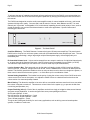
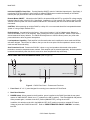
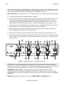
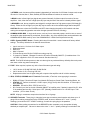
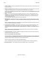
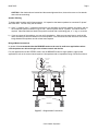
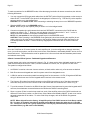
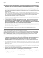
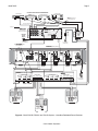
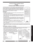
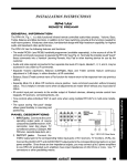
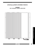
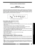
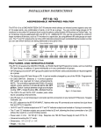
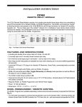
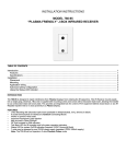
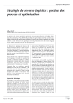
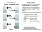
INSTALLATION INSTRUCTIONS MODEL PA635 SIX CHANNEL POWER AMPLIFIER WITH IR CONTROL TABLE OF CONTENTS Section Title Page GENERAL INFORMATION ................................................................................................................................. 2 PA635 PANEL AND FEATURE DESCRIPTIONS................................................................................................. 3 Factory Default Settings, Item #9............................................................................................................ 5 INSTALLATION RC68+ (or RC68) PROGRAMMER / REMOTE CONTROL ..................................................................... 6 PHYSICAL LOCATION AND MOUNTING .............................................................................................. 9 CONNECTING THE PA635 .............................................................................................................................. 10 Stereo Mode Connections ..................................................................................................................... 10 Speaker Phasing................................................................................................................................... 11 Bridged Mode Connections ................................................................................................................... 11 Typical Applications............................................................................................................................... 12 A Basic Common IR Bus System - Dedicated Keypads and Remotes.................................................... 12 A Basic Dedicated IR System - Non Dedicated Keypads and Remotes.................................................. 14 Connecting the REMOTE MASTER ON/OFF CONTROL Terminals ...................................................... 16 A Multi-Zone Power Managed System, using a ZPR68-10, a GATEKEEP-IR™ and a PA635 ............... 16 TROUBLE SHOOTING...................................................................................................................................... 18 SPECIFICATIONS............................................................................................................................................. 19 Page 2 Model PA635 GENERAL INFORMATION To enhance the ease of installation and obtain optimum performance from the PA635, we recommend that you first become familiar with all its features and special capabilities by studying the descriptions and instructions in this manual. The PA635 was designed to meet the audio power amplifier needs of custom installed multi-room, multi-zoned systems with high sonic quality. Common and Local IR control of Volume, Mute, Balance and OFF, for each channel pair, is provided. Its bridgeable 6-5-4-3 multi-channel capability permits a wide variety of uses, such as enough channels to run surround sound home theater or multi-room applications. Specific features and technology are as follows: 1 2 3 POWER PA635 SIX CHANNEL AMPLIFIER Figure 1 – The Model PA635 Cost/Size Efficiency. The PA635 features 6 conservatively rated 35-watt power amplifiers. This permits each PA635 to drive 3-zones in a multi-zone system, each with a 35 watts/channel stereo amplifier per zone. The rack mountable low profile design, using a large single multiple filtered power supply, delivers high quality at a reasonable price. IR Controlled Volume Level. Volume can be ramped from zero output to maximum for individual channel pairs, or, as group through the Common Bus inputs, using IR volume control commands from an RC68+ (or RC68). The maximum input sensitivity at full volume is 0. 5 volts for rated output (35 Watts/channel). Local or Common Bus. Each stereo pair can be fed audio individually via their LOCAL inputs from differing zones or sources. In addition, a single source can be fed, via the COMMON Bus, to some or all stereo pairs as desired. This flexibility permits the installer to drive as many as three rooms in stereo as a single zone system, or three rooms in stereo as a three-zone system --- or divide them up for a combination of both. Volume Setting Capabilities. The installer has the option of using the volume control of the PA635 as the sole volume control for a zone or the system, or to adjust the PA635 volume to a desired fixed level and use the volume action of a connected preamp instead. Max-V Setting. This allows the amplifier to be set to deliver a controlled maximum sound level into a zone when the volume is ramped to maximum. This acts as a volume limiter for the system (e.g. to prevent the kids from over-driving wall speakers, etc.). Output Flexibility (6-5-4-3). Each of the six amplifiers can be driven singly or bridged to allow several channel and power output capabilities. It can be configured into seven power packages as follows: Six 35-watt amplifiers - 6 total. One 150 and four 35-watt amplifiers - 5 total. Two 150 and two 35-watt amplifiers - 4 total. Three 150-watt amplifiers - 3 total. This gives the PA635 great flexibility for use in many applications, such as driving surround sound speaker systems, in addition to multi-room. © 2001 Xantech Corporation. Model PA635 Page 3 Individual ON/OFF of Amp Pairs. Permits Standby ON/OFF control of individual channel pairs. Specifically, it permits the STATUS outputs (12 Volts On/Off) of Xantech ZPR68 zones to switch the Standby of the PA635 channel pairs (CI) On and OFF with zone ON and OFF commands. Remote Master ON/OFF. Allows the entire PA635 to be powered ON and OFF by a positive DC voltage ranging between 5 and 30 volts (16mA @ 12V). Specifically, it permits the 12 Volt common CO (Control Output) on the Xantech ZPR68 to power one or more PA635's ON and OFF automatically with first zone ON and last zone OFF commands. CAUTION: When powering up multiple PA635’s, a delay of 2 or more seconds should be incorporated between “power on” using multiple Xantech AC2’s. Default settings. As received from the factory, Volume level is set to 1 Volt for 3 Watts output, Balance is centered and Mute is OFF, for all channels. Also, pressing the LEVEL (System) RESET switch 2 times within 1 second restores all factory defaults. The PA635 will always return to last set values (volume, etc.) after main power shut down or after any power interruptions. Low Impedance Capability. Each amplifier is 4-Ohm safe under music conditions in stereo mode and 8-Ohm safe when bridged. This means, for instance, that you can drive two pairs of 8-Ohm speakers in stereo mode in each zone with ease and safety. Auto Protection Circuit. Protects the PA635 if a short or very low impedance is detected at the speaker terminals or excessive temperatures are reached. Each amplifier pair is protected separately. Normal operation is restored automatically when the short is removed or when temperatures drop sufficiently. PA635 PANEL AND FEATURE DESCRIPTIONS (refer to Figure 2) 1 2 2 1 2 3 POWER PA635 SIX CHANNEL AMPLIFIER 3 4 Figure 2 – PA635 Front Panel – Features and Functions 1. Front Panel. 19" x 3 ½" panel designed for mounting into a standard 19" Rack Panel. 2. Rack Panel Handles. 3. POWER Switch. When pressed to the IN position, power is applied to the PA635 [provided the rear panel master AC LINE ON/OFF Switch, item 17, is placed in the ON (I) position]. This is the MANUAL ON position. When pressed again, it releases to the OUT position (MANUAL OFF), turning the unit OFF. In addition, this switch must be left in the MANUAL OFF (OUT) position to permit an external DC Control Voltage to power the PA635 ON and OFF. Refer to "REMOTE MASTER ON/OFF CONTROL" terminals, item #13. © 2001 Xantech Corporation Page 4 Model PA635 NOTE: The PA635 may also be powered ON/OFF with an external AC line switch into which the power cord of the PA635 is plugged (such as the switched AC outlet of a preamp, timer, etc. with a 10A rating). For this type of operation, leave the POWER switch depressed to the MANUAL ON position. 4. Status LED Indicators. These indicators, one for each channel pair, provide the following status information: a) They show Power ON/OFF and Standby ON/OFF conditions. b) They flash Amber 5 times during power up, then turn steady Green when Power On Mute releases. This action occurs whether the unit is powered ON and OFF by the POWER switch (item # 3) or by a DC voltage applied to the REMOTE MASTER ON/OFF CONTROL terminals (item #13). Be sure the rear panel master AC LINE ON/OFF Switch, item #17, is set to the ON (I) position for the above to occur. c) They will go off when the Standby OFF IR command is received. Sending a MUTE OFF command will restore operation. Also, each LED blinks with Volume action for that channel. d) A Mute command will cause the channel LED to blink Green (Red if Volume is within 5 dB of Max-V). Mute is released when any other PA635 command is sent. e) Changing an IR Code Group will cause them to blink Amber, confirming the change has taken effect. f) When the volume level is increased to a range within 5 dB of MAX-V, the LED color changes from Green to Red. NOTE: Red indicates that volume gain setting is approaching maximum --- not an indication of power output level. 9 8 5 7 6 5 7 6 5 7 6 18 10 COMMON AUDIO BUS WARNING TURN POWER OFF BEFORE CHANGING MODES LEFT MODE STEREO MONO BRIDGED RIGHT 1 LEFT CAUTION COMMON LOCAL RISK OF ELECTRIC SHOCK. DO NOT OPEN 5-30 VOLTS DC ® 14 13 16 IR IN CI STATUS + GROUND -- + BRIDGED -- COMMON LOCAL TURN POWER OFF BEFORE CHANGING MODES LEFT MODE STEREO MONO BRIDGED + BRIDGED -- SPEAKER LEFT WARNING RIGHT 2 MODE STEREO MONO BRIDGED CI GROUND STATUS IR IN LEVEL RESET RIGHT 3 COMMON LEFT AC 120V 60 HZ 2 AMP + BRIDGED -- SPEAKER RIGHT + -- -- + FUSE 6.25 AMP SLOW BLOW LOCAL CI GROUND STATUS IR IN RIGHT REMOTE MASTER ON/OFF CONTROL CI GROUND STATUS IR IN LEFT SPEAKER RIGHT LEFT + -- -- + RIGHT + -- -- + AC LINE ON/OFF 15 11 12 11 12 11 12 17 Figure 3 – PA635 Rear Panel – Features and Functions 5. Line Inputs. These RCA-type jacks are the audio inputs for each of the amplifier pairs. Connect them to the OUTPUT jacks of the driving preamp with good quality RCA-type patch cables. Note that the inputs are marked LEFT-1-RIGHT, LEFT-2-RIGHT, etc., signifying the stereo channel pairs. Both the LEFT and RIGHT jacks are also active when the MODE switch (item #7) is set to the MONO or BRIDGED mode. 6. COMMON BUS / LOCAL Switch. Switches the amplifier stereo pair inputs between the LOCAL (LEFT/RIGHT) jacks, item #5 and the COMMON AUDIO BUS (LEFT/RIGHT) jacks, item #8. In this way, each amplifier pair can be driven by separate zones or sources or from a common source via the COMMON AUDIO BUS. 7. MODE Switch. Switches the amplifier pair between STEREO, MONO and BRIDGED modes. © 2001 Xantech Corporation. Model PA635 Page 5 In STEREO mode, the two amplifiers operate independently of each other for 35 Watts of output each, except IR control of Volume, Max-V, Mute, Standby OFF/ON and Balance functions is common to both. In MONO mode, left and right input signals are summed internally for Mono output from each of the two amplifiers. Also, either the Left or Right (item #5) input may be used if the source is already a Mono signal. In BRIDGED mode, the two amplifiers are bridged for a single channel of high power output (150 Watts @ 8 Ohms). Either the Left or Right input (item #5) may be used to drive the resultant single channel amplifier. CAUTION: Be sure to have the POWER turned OFF when changing the position of this switch and when making the corresponding speaker connection changes (see also item #12, following). 8. COMMON AUDIO BUS. A single audio source, such as from a connected preamp, can drive one or more of the amplifier pairs simultaneously, as desired, from this Bus. Any of the amplifier pairs can be switched to the COMMON AUDIO BUS at will by use of the COMMON BUS / LOCAL Switch (see also item #6). 9. LEVEL (System) RESET Button. Pressing this button 2 times within 1 second restores all factory default settings. The factory defaults for all channels are as follows: • • • • • • Input Level set to 1 Volt rms for 3 Watts output. Balance centered. Mute OFF. MAX-V Cleared. IR Code Group set to B0 (the PA1235 uses code group A0). CI (control in) disabled. Changes CI control to IR control of Standby ON/OFF. (CI enables when +5 to +30 VDC is applied to CI for 2 or more seconds. See also item #11). NOTE: The PA635 will always return to last set values (plus any unaltered factory defaults) after main power shut down or after any power interruptions. 10. FUSE. When required, replace only with a fuse of the same type and rating: • • • 120 V Version: 6.25 AMP 250 VAC, SLOW BLOW. 240 V Version: 3.15 A Time-Lag 250 VAC. Replacement with a fuse of higher rating will not protect the amplifier and will void the warranty. 11. IR IN, STATUS, GROUND and CI Terminals. Removable, 4-Terminal, screw type plug-in connector. • • • • IR IN = IR Signal. Receives IR Input from Xantech IR Receivers, Smart Pads, Connecting Blocks, etc. STATUS Out. Delivers a constant +12 VDC output (9V @ 70 mA) with ON condition. 0 Volts output = OFF (Standby). GROUND. Ground for IR IN, STATUS out & CI in. CI = Control Input. Use for control of Standby ON/OFF of amplifier pairs, if desired, instead of by IR. After CI is enabled (see item #9), 0 Volts input = OFF (Standby) condition and +5 to +30 VDC input = ON condition. (12V in draws 16 mA). NOTE: All plug-in connectors accept wire sizes from 24 to 12 gauge. 12. SPEAKER Terminals. These plug-in 4-terminal screw type connectors permit speaker wire sizes up to 12 gauge. When making connections for the STEREO mode, be sure to observe the "+” and "–" polarity markings, just under the LEFT & RIGHT markings, for each wire pair going to the speakers. CAUTION: When making connections for the BRIDGED mode, remember, only one speaker is being attached per amplifier pair. Be sure to observe the outer "+” and "–" polarity markings on each side of the © 2001 Xantech Corporation Page 6 Model PA635 word "BRIDGED" on the panel above the 4-terminal connector when connecting the 2-conductor wire to the speaker. 13. REMOTE MASTER ON/OFF CONTROL. This 2-terminal connector allows the entire PA635 to be powered ON and OFF by a control voltage ranging between 5 and 30 Volts DC (16mA @ 12 V). Be sure to observe the marked polarity. For instance, the 12 volt common CO (Control Output) of the Xantech ZPR68 preamp will power the PA635 ON and OFF automatically with the first zone ON and last zone OFF commands. The DC Voltage must be applied continuously to retain the ON condition and drop to less than 0.5 Volt to switch to the OFF condition. NOTE: The front panel POWER switch (item #3) must be left in the Manual OFF (Out) position and the Master AC Line Switch (item #17) set to ON (I) to permit the REMOTE MASTER ON/OFF CONTROL to operate. See also CAUTION notes, Fig. 9. 14. Rear Panel ON/OFF LED. This LED indicates the power ON/OFF condition of the entire PA635, whether activated by a REMOTE MASTER ON/OFF CONTROL voltage (item #13) or from the front panel POWER switch (item # 3). 15. Common IR IN and STATUS Connector. This 4-terminal connector provides the same type of IR control functions as that of the individual amplifier pairs (item #11) except they apply to all amplifier pairs in common. That is, IR commands for Volume, Mute, etc., control all amplifier pairs together. NOTE: Individual control of amplifier pairs is possible, however, through the Common IR IN, provided the IR Code Group is changed on amplifier pairs you wish to control separately. The STATUS output goes high and low with the AC Power ON/OFF state of the entire PA635. It does not respond to a Common IR OFF/ON (Standby) condition. 16. Grounding Screw. Provides a means for chassis connection to earth ground or to other A/V products to aid in the reduction of system noise, etc., where needed. 17. Master AC LINE ON/OFF Switch. Turns power OFF to the entire PA635, regardless of IR, Control IN, or front panel POWER switch conditions. Must be placed in the ON (I) position for the other power switching functions to work. 18. 3-Conductor AC Line Cord Receptacle. Standard IEC male receptacle for plug-in of a 3-conductor power line cord. Depending on the application, plug the line cord into a switched or un-switched 120V 60 Hz AC outlet (or 240 VAC 50 Hz on the 240 V version). RC68+ (or RC68) Programmer / Remote Control The RC68+ Programmer (available separately) contains all the commands necessary to operate the IR control functions of the PA635. You will need it to program universal learning devices such as the Xantech URC-2 learning remote, Xantech SmartPads, 590-10 Programmable Controller, 710 Fone Link, etc., with commands that operate the PA635. NOTE: The RC68+ codes operate many other Xantech models as well, such as the RGC11, CC12, ZPR68, etc. Therefore, only the button descriptions that apply to the operation of the PA635 are listed below. All others should be ignored. CAUTION: While the RC68+ can be used as a handheld remote control, it is highly recommended it not be given to the final user for the following reasons: • Since it includes adjustable code groups, the user may inadvertently alter the installer configurations. • Also, since the user will require IR commands from other brands of equipment to control the total system, in addition to those of the PA635, all commands should be consolidated into one learning device, for ease of use. © 2001 Xantech Corporation. Model PA635 Page 7 Applicable RC68+ Button Descriptions 1 10 A 80 2 B 48 C 10 90 1 2 3 4 00 C0 50 D0 5 A ADJ-OFF 6 INPUT 7 01 41 8 40 A0 B0 21 20 E0 30 70 F0 61 TREBLE BASS Z-ADJ VOL 60 88 18 98 9 GLOBAL 09 MUTE 3 08 A8 38 B8 ON OFF 28 E8 78 F8 E-FLAT LAST MAX-V TRIM 68 C8 58 D8 49 OFF 29 8 7 69 C-BAL E1 89 C9 A9 E9 71 19 59 39 79 F1 99 D9 B9 F9 6 5 4 RC68+ PROGRAMMER Figure 4 – The RC68+ Programmer 1. IR Emitter Lens. 2. Instant Volume Presets. These commands allow random access or direct preset activation of any of 12 fixed preset levels on the PA635. This is useful when setting up "audio scene" ambiance levels for rooms or partial mute actions. The RC68+ buttons that select a fixed level attenuation below Max. Volume is as follows: RC68+ Button 38 10 00 C0 50 D0 40 A0 30 B0 20 E0 PA635 Level Attenuation in dB (Mute ON) (C & 01 on RC68) (1) (2) (3) (4) (5) (6) (7) (8) (Treble Up Arrow) (Bass Up Arrow) > 90 (Min. Volume) 60 52 44 36 30 24 18 14 10 6 0 (Max. Volume) 3. OFF Command. Turns the amplifier pairs (both LOCAL and COMMON) to Standby OFF mode (audio mute and 0.0VDC on Status). The "Standby OFF" mode remains until the MUTE OFF command is sent. NOTE: This command is inhibited automatically when the CI terminal is driven high with an external control voltage. Refer also to items 9 and 11, Fig. 3. © 2001 Xantech Corporation Page 8 Model PA635 4. C-BAL Command. Instantly returns the balance to the Center position (equal volume in each channel) from any previous setting. 5. Balance Commands. When the Balance "arrow" buttons are pressed, the audio output will move to the left or right (with a 2 dB/step reduction in the attenuated channel) with each left or right press. NOTE: These commands do not ramp. That is, no change will occur if the BALANCE buttons are held down continuously! 6. MAX-V. This command saves a maximum desired volume level for a zone or rooms (both LOCAL and COMMON). The volume is first adjusted to what is desired as a maximum level. The MAX-V button is then pressed, locking in this setting. This acts as a volume limiter for the system (e.g. to prevent the kids from over-driving wall speakers, etc.). To unlock the MAX-V setting, press the ADJ-OFF button (item #10). 7. MUTE ON/OFF. Separate ON / OFF Mute commands give positive mute action without knowing the actual mute status. This is very helpful in a remote room where commands are sent “blind” without any visual aids for status. NOTE: In addition to MUTE OFF, the muted condition can be released with VOLume (item #8), Preset Level (item #2) and Balance (items #4 & 5) commands. 8. Volume Up/Down Commands. When pressed in individual steps, volume increase and decrease is 2 dB per step over a range of 0 dB (Max.) to -60 dB. The next step below -60 dB is OFF (> -90 dB). When pressed continuously, volume level will change (ramp) continuously in 1 dB steps. See also MAX-V settings (item 6). NOTE: Volume action of the PA635 has been designed specifically to ramp more quickly in the DOWN direction and more slowly in the UP direction. 9. Code Group Numbers. The PA635 is capable of being set to 55 different code groups, both individually as amplifier pairs and collectively as a group. Be sure to set the RC68+ to the same number! It may be necessary to change the PA635 amplifier pairs to different code groups if you wish to address each pair individually from the COMMON IR BUS (item #15, Fig. 3) or an external common IR bus network when using other Xantech PA635's in large systems, to avoid mutual interaction. Refer to the RC68+ instructions for code group setting procedures. NOTE: As shipped from the factory, all amplifier pairs in the PA635 are set to code group number B0. 10. ADJ-OFF Command. This command unlocks a previous MAX-V setting. See also item #6. © 2001 Xantech Corporation. Model PA635 Page 9 INSTALLATION - PHYSICAL LOCATION AND MOUNTING When you mount the PA635, you should plan its location carefully. Pay attention to each of the following factors: Upper shelf, component, wall, etc. PA635 Keep perforations on top cover free of obstructions for max. cooling effect. To maximize air flow, route single large opening in lower shelf. Convection Airflow 2-inch spacing (minimum) Keep perforations on bottom plate free of obstructions. Figure 5 – Horizontal Mounting 1. The amplifier is convection cooled - it depends on the natural free flow of air up through the slot perforations in the bottom plate, over the internal heat dissipating fins, then out the top cover, for adequate cooling. 2. If mounted in an equipment cabinet or other confining location, allow at least 2 inches of space above the top cover (see Fig. 5). Be sure there are large openings in the shelf below the unit and in the cabinet to allow the entry of cool air and the escape of warm air. NOTE: Do not remove feet in shelf-top installations. 3. If the cabinet contains other heat generating components or you are using several PA635's in a large multizone system, you will have to pay even closer attention to adequate ventilation. 4. Do not hesitate to use fans (quiet, boxer type), if necessary, to ensure a constant flow of air through the PA635's and the other heat generating components. 5. When mounting in a 19" (483mm) rack, adding a single RU (Rack Unit) above and below the PA635 will improve convection in heavy use applications (one Rack Unit size = 1-3/4" (44.5mm) in height). 6. In multi-zone installations, you will have large bundles of wire and cable to accommodate audio, video and speaker connections. Be sure to allow enough room for the leads and dress them in such a manner so as not to block airflow. 7. The PA635 is designed for mounting into standard 19" Rack Panels or on flat horizontal surfaces. When mounting into a 19" rack, use the rack panel cup washers and screws supplied. NOTE: You should consider some sort of rear support for rack mounted units when used in mobile applications or when located in seismically-active areas. © 2001 Xantech Corporation Page 10 Model PA635 CONNECTING THE PA635 When making connections to the PA635 be sure the power cord is unplugged. Proceed as follows: Preamp Outputs ZPR68, etc. VIDEO RCA Type Patch Cords L AUDIO R Set MODE Switch to STEREO position 1 PA635 Rear Panel LEFT 1 MODE STEREO MONO BRIDGED RIGHT COMMON CI GROUND STATUS IR IN LOCAL + BRIDGED -- SPEAKER LEFT RIGHT + -- -- + Be sure speakers are connected with correct polarity as shown. + + Wall speakers, shelf speakers, etc. Left Right Figure 6 – Stereo Mode Connections Stereo Mode Connections 1. Using good quality RCA-type patch cables, connect the L and R OUTPUT jacks of the driving preamp to the LEFT and RIGHT input jacks on the PA635. Do this for each amplifier pair. Refer to Fig. 6. 2. Slide the MODE switch to the STEREO position. 3. Using good quality speaker wire, connect the individual speaker leads to the 4-terminal "SPEAKER" connectors on the PA635 as shown. 4. The PA635 is 4-Ohm safe in Stereo Mode. Make sure the impedance presented to the speaker terminals by the speakers (or any combination of speakers) is 4-Ohms minimum. 5. Be sure to observe correct polarity by connecting the "+" and "–" terminal from each channel on the PA635 to the corresponding "+" and "–" terminals on each speaker. This will ensure correct "phasing". See Fig. 6 and Speaker Phasing, following. Since the connectors are removable, you may unplug them for ease of lead assembly. 6. As a rule of thumb, use 18 gauge speaker wire for speaker runs up to 30' (9m), 16 gauge up to 70' (21m), and 14 gauge up to 150' (39m). The 4-terminal connectors accept wire sizes up to 12 gauge max. 7. Strip the insulation back about 1/4" (6mm) and twist the strands on each lead to prevent fraying. © 2001 Xantech Corporation. Model PA635 Page 11 CAUTION: After lead ends are inserted and the screws tightened down, be sure there are no free strands that could cause shorting! Speaker Phasing To obtain stable imaging and full bass response, it is imperative that stereo speakers be connected "in phase" with each other. You can verify this as follows: a) If the "+" (positive) and "–" (negative) terminals on your speakers are correctly marked, and visible, and you have wired the system as shown in Figs. 6 and 7, then the system will be "in phase". No further action is required. Most manufacturers identify the positive terminal with a red binding post, a "+" sign, or a red dot. b) If you are unsure of the markings, you can verify the phasing. Using a mono sound source, such as AM radio, alternately reverse the leads to one of the speakers. Pick the connection that delivers a solid center image between the speakers as well as best bass response. Bridged Mode Connections In general, it is recommended that the BRIDGED mode not be used in multi-room applications where several speakers are driven through room volume controls and the like. For such applications use the STEREO mode. Use the BRIDGED mode for single speaker, higher power applications, such as in surround sound systems. Use speakers with an impedance rating of 8-Ohms minimum. Preamp Outputs ZPR68, etc. VIDEO RCA Type Patch Cords L AUDIO Set MODE Switch to BRIDGED position R 1 1 RIGHT LEFT COMMON 1 RIGHT COMMON LOCAL CI GROUND STATUS IR IN LOCAL MODE STEREO MONO BRIDGED + BRIDGED -- + BRIDGED -- SPEAKER LEFT CI GROUND STATUS IR IN LEFT MODE STEREO MONO BRIDGED PA635 Rear Panel SPEAKER RIGHT LEFT + -- -- + RIGHT + -- -- + Be sure speakers are connected with correct polarity as shown. + + Wall speakers, shelf speakers, etc. Left Right Figure 7 – Bridged Mode Connections © 2001 Xantech Corporation Page 12 Model PA635 To make connections for the BRIDGED mode, follow the steps given before for stereo connections, but with the following differences: 1. You may connect the RCA-type patch cables from the OUTPUT jacks of the driving preamp or other source to either the LEFT or the RIGHT input jacks of the bridged pair, as shown in Fig. 7. Do this for just the amplifier pairs you wish to run in the bridged mode. CAUTION: Be sure Power is OFF when connecting or switching the amp into or out of BRIDGED operation. 2. Slide the MODE switch to the BRIDGED position. NOTE: Do this only on the amplifier pairs you wish to run in the bridged mode! 3. Connect one speaker wire pair between the 4-terminal "SPEAKER" connectors on the PA635 and the speakers as shown in Fig. 7. Be sure to use only the two outer terminals marked "+” and "–" on the 4terminal connector as shown on the panel for BRIDGED connections. NOTE: Only one speaker is connected per amplifier pair in the BRIDGED mode! CAUTION: When operating in the BRIDGED mode (particularly when bench testing the amplifier) do not make a ground or any other kind of connection to the amplifier speaker terminals other than those to the individual speakers as shown. Failures caused by inappropriate connections are not covered under the warranty. Typical Applications Since the PA635 has an IR control system for each amplifier pair, it can be configured so that each individual room, in a multi-room system, can have Line Level Volume, Mute, Balance, and Standby ON/OFF action via IR or Smart Pad control. This eliminates the need for speaker level volume controls and their attendant power losses and reduced sound quality. A Basic Common IR Bus System - Dedicated Keypads and Remotes. A typical system using a low cost approach is shown in Fig. 8. It does require that a dedicated remote be used in each room that has an IR receiver - that is, remote commands for Volume, etc., are specific for each room. The system is configured as follows: 1. An RS41AV is used as a low cost 4-source selector, an ideal solution when only a few sources are desired. 2. Both IR receivers and keypads are used for system control from designated rooms. 3. A CB18 is used as a convenient parallel connecting block for the common +12 VDC, IR signal and GND bus wiring for all the home runs from the keypads and IR receivers in the remote rooms. 4. The Common IR is taken from the #2 connector on the CB18 (connection to any of the other connectors would also work) and run to the Common IR IN on the PA635 with a 2-conductor lead. Refer to Fig. 8. 5. To provide common IR control to the RS41AV and the Source Components and to power the keypads and IR receivers, three leads are connected between the CB18 and a 789-44 Connecting Block. 6. Since a common IR bus is used to keep costs low, each of the amplifier pairs on the PA635 must be set to a different IR Code Group number, so that Volume, Mute, Balance and Standby ON/OFF in each room can be adjusted independent of the others. To make Code Group changes, refer to the RC68+ Programmer Instructions. NOTE: When shipped from the factory, all amplifier pairs of the PA635 are set to Code Group number B0. You may, for example, leave the #1 amplifier pair at B0 and change the other two to C0 and D0, etc. Just be sure not to use a group number that is used by any other Xantech product connected on the same IR bus (e.g. #20 used on the RS41AV). © 2001 Xantech Corporation. Model PA635 Page 13 CONTROLLED SOURCE COMPONENTS CD Changer L L R Cassette DecK Satellite Receiver AM/FM Tuner R V L L R 286M Dual Blink-IR R Mouse Emitters (2) RCA type Patch Cords 6015900 To Video Distribution (if used) 3 4 RS41AV VIDEO REMOTE SWITCHER IR CONFIRM ® EMITTERS SYLMAR, CA MADE IN U.S.A. AUDIO LEFT RS41AV Power Supply 3.5mm to-stripped-ends mono cable (7) AUDIO RIGHT CONNECTING BLOCK Type Power Supply POWER 15VAC V V G IR IN INPUT 789-44 782 OUTPUT White striped side To AC MAINS (Unswitched) ® 12VDC GND Audio/Video Remote Switcher 2 IR IN 1 +12 VDC RS41AV STATUS IR Signal To AC MAINS (Unswitched) PA635 (rear panel) COMMON AUDIO BUS WARNING LEFT TURN POWER OFF BEFORE CHANGING MODES MODE STEREO MONO BRIDGED RIGHT 1 LEFT CAUTION COMMON RISK OF ELECTRIC SHOCK. DO NOT OPEN LOCAL MODE STEREO MONO BRIDGED 2 5-30 VOLTS DC ® CI IR IN STATUS + GROUND -- + BRIDGED -- COMMON LOCAL LEFT MODE STEREO MONO BRIDGED 3 RIGHT COMMON LEFT AC 120V 60 HZ 2 AMP SPEAKER RIGHT LEFT + -- -- + RIGHT AC LINE ON/OFF + -- -- + TO ROOM 3 SPEAKERS TO ROOM 2 SPEAKERS IR FUSE 6.25 AMP SLOW BLOW LOCAL + BRIDGED -- SPEAKER RIGHT + -- -- + TO ROOM 1 SPEAKERS +12V TURN POWER OFF BEFORE CHANGING MODES + BRIDGED -- SPEAKER LEFT WARNING RIGHT CI GROUND STATUS IR IN LEVEL RESET CI GROUND STATUS IR IN RIGHT CI GROUND STATUS IR IN LEFT REMOTE MASTER ON/OFF CONTROL To AC MAINS (Unswitched) CB18 Parallel Connecting Block +12 VDC IR 1 2 3 4 5 6 7 8 9 GND GND L L R V G ST R V G ST IR IR Smart Pad3 Smart Pad3 ROOM 3 ROOM 1 L R V G ST IR 780-80 "J" Box IR Receiver ROOM 2 Figure 8 – Basic PA635 and RS41AV System – Requires Room-Dedicated Remotes © 2001 Xantech Corporation IR RCVR Page 14 Model PA635 CAUTION: When changing the group numbers, you must connect an IR receiver to each amplifier pair's IR input (item 11, Fig. 3) one at a time. You cannot use the Common IR Input (item 15, Fig. 3) as this will change them all to a different, but same number. 7. After the Code Groups are set up, "teach" volume and other commands from the RC68+ Programmer (Fig. 4) into learning remote controls (and the keypads) dedicated to each room. Be sure to set the RC68+ to the specific Code Group Number that corresponds to the ones chosen for each of the amplifier pairs, during this "teaching" process. NOTE: With a Common IR Bus system, you cannot carry the same remote control from room-toroom. You must use a dedicated learning remote (such as the Xantech URC versions) for each room into which you have "taught" the specific RC68+ Code Group that operates the specific PA635 Amplifier Pair that controls the volume, etc., for that room! If you wish to carry remotes that have the same codes from room-to-room, that is, Non-Dedicated Remotes, use the IR System shown in Fig. 9. 8. To keep the system cost low, no AC power management is included. The user would need to operate the power switching for each component individually, using front panel power switches, or IR, as appropriate. Individual room Standby ON/OFF is provided, however. The STATUS of Standby ON/OFF is indicated at the IR receivers and keypads via the STATUS line connection to each room, as shown. 9. This system is primarily set up to distribute music to each room. A video feed to a single room could also be done at low cost. However, video distribution to all rooms would add additional layers of complexity and cost that would best be handled by a ZPR68-10. 10. When connecting speakers for each room, be sure to observe correct polarities as shown in Fig. 6. A Basic Dedicated IR System - Non-Dedicated Keypads and Remotes. A typical system of this type is shown in Fig. 9, where each remote room has a Dedicated IR path going to the PA635 amplifier pair that controls it. The IR bus is not connected in common as it is in Fig. 8. It eliminates the need for dedicated remotes, allowing you to carry the same remote(s) from room-to-room - that is, remote commands for Volume, Mute, etc., will work in any room from the same remote. This system is similar in many respects to the previous system (Fig. 8), but differs as follows: 1. A 796-20 Six Zone Connecting Block is used to "zone" individual IR control signals to each amplifier pair of the PA635 for Volume, Mute, Balance and Standby ON/OFF action in each room. It also carries a "COMMON" IR signal to a 789-44 Connecting Block for control of the RS41AV Remote Switcher and the Source Components. 2. Note that the ZONE numbers on the 796-20 do not agree with the room or amplifier pair numbers. This is of no consequence; it is only necessary that each room's keypad or IR receiver connects to a different ZONE IR INPUT on the 796-20. 3. Since the 796-20 channels the IR from each room to it's specific PA635 amplifier pair, each amplifier pair can use the same IR Code Group (the factory default B0). 4. While use of the 796-20 entails some added expense, it reduces programming time for both the hand-held remotes and the keypads, in addition to providing additional convenience to the user. 5. The desired volume and other commands from the RC68+ Programmer (see Fig. 4) need to be "taught" into learning remote controls (such as the Xantech URC types) and Smart Pads used in the system, either directly or by using Dragon Drop IR™. © 2001 Xantech Corporation. Model PA635 Page 15 CONTROLLED SOURCE COMPONENTS CD Changer L L R Cassette DecK Satellite Receiver AM/FM Tuner R V L L R 286M Dual Blink-IR R Mouse Emitters (2) RCA type Patch Cords IR Signal To Video Distribution (if used) 4 RS41AV VIDEO REMOTE SWITCHER ® RS41AV Power Supply AUDIO RIGHT INPUT IR CONFIRM SYLMAR, CA MADE IN U.S.A. AUDIO LEFT EMITTERS 782 789-44 CONNECTING BLOCK Type Power Supply POWER 15VAC V V G IR IN OUTPUT ® 12VDC White striped side To AC MAINS (Unswitched) IR RCVR To AC MAINS (Unswitched) 6015900 3.5mm to-stripped-ends mono cable (7) GND 3 IR IN 2 STATUS 1 Audio/Video Remote Switcher +12 VDC RS41AV PA635 (rear panel) COMMON AUDIO BUS WARNING LEFT TURN POWER OFF BEFORE CHANGING MODES MODE STEREO MONO BRIDGED RIGHT 1 LEFT CAUTION COMMON RISK OF ELECTRIC SHOCK. DO NOT OPEN LOCAL MODE STEREO MONO BRIDGED 2 IR IN CI 5-30 VOLTS DC ® STATUS + GROUND -- + BRIDGED -- TURN POWER OFF BEFORE CHANGING MODES COMMON LOCAL LEFT A A B B RIGHT AC LINE ON/OFF TO ROOM 3 SPEAKERS â SYLMAR CA, MADE IN U.S.A. ZONE 6 A AC 120V 60 HZ 2 AMP + -- -- + TO ROOM 2 SPEAKERS ZONE EMITTERS ZONE IR INPUTS ZONE 6 LOCAL LEFT SIX ZONE CONNECTING BLOCK / EXPANDER ZONE 5 COMMON SPEAKER RIGHT + -- -- + 796-20 ZONE 4 FUSE 6.25 AMP SLOW BLOW RIGHT 3 + BRIDGED -- SPEAKER RIGHT + -- -- + TO ROOM 1 SPEAKERS ZONE EMITTERS LEFT MODE STEREO MONO BRIDGED + BRIDGED -- SPEAKER LEFT WARNING RIGHT CI GROUND STATUS IR IN LEVEL RESET CI GROUND STATUS IR IN RIGHT REMOTE MASTER ON/OFF CONTROL CI GROUND STATUS IR IN LEFT ZONE 5 ZONE IR INPUTS ZONE 9 ZONE 4 +12 IN G +12 IN G +12 IN G B ZONE 7 ZONE 8 ZONE 9 A A A B B ZONE 8 ZONE 7 COMMON +12 IN G +12 IN G +12 IN G +12 OUT G To AC MAINS (Unswitched) B GND IR +12 VDC L L R V G ST V G ST IR Smart Pad3 R L R IR Smart Pad3 ROOM 3 ROOM 1 V G ST IR 780-80 "J" Box IR Receiver ROOM 2 Figure 9 – Basic PA635, RS41AV and 796-20 System – Uses Non-Dedicated Room Remotes © 2001 Xantech Corporation Page 16 Model PA635 Connecting the REMOTE MASTER ON/OFF CONTROL Terminals As mentioned under "PA635 PANEL AND FEATURE DESCRIPTIONS", the REMOTE MASTER ON/OFF CONTROL terminals allow the power to the entire PA635 to be turned ON and OFF by a remotely applied DC Voltage. Fig. 10 is a typical applications using this feature. Using a DC Power Adapter as a Control Voltage Fig. 10 illustrates how a PA635 can be switched ON and OFF via the switched AC outlet on the rear of a preamplifier or other control center. When the preamplifier Power Switch is switched ON, power is applied to the DC adapter which in turn applies 5 V to 30 VDC to the PA635, switching it ON. Similarly, when the preamplifier is switched OFF, the DC voltage to the PA635 is removed, turning it OFF. CAUTION: The output voltage of some adapters, such as the 781RG, drops off too slowly to provide a quick turnoff for the PA635. Therefore, when using any adapter (12 VDC max), always connect the included 220 Ohm 1 Watt resistor in shunt with the REMOTE MASTER ON/OFF CONTROL terminals as shown in Fig. 9. Failure to do so may result in blowing of the power line fuse (item #10, Fig. 3). NOTE: Do not use the 220 Ohm resistor when connecting to the CO terminals of a ZPR68! This must be the positive (+) lead (white striped lead on Xantech Power Supply Adapters) PA635 (portion of rear panel) Preamplifier, Control Center, etc. COMMON AUDIO BUS LEFT WARNING TURN POWER OFF BEFORE CHANGING MODES IR IN STATUS + LEVEL RESET CI -- 5-30 VOLTS DC ® 5V to 12 VDC Adapter, such as a Xantech 781RG, plugged into a Switched AC Outlet on Preamplifier RIGHT REMOTE MASTER ON/OFF CONTROL GROUND (+) CAUTION: You must use the included 220 ohm resistor. Figure 10 – Using the Remote Master On/Off Control Terminals A Multi-Zone Power Managed System, using a ZPR68, a GATEKEEP-IR™ and a PA635 Fig. 10 shows a PA635 in a typical multi-room system with a Xantech ZPR68-10 six-zone preamp and a GATEKEEP-IR. The PA635 has been designed specifically to work well with both Zone and All-Zone ON/OFF management as rendered by the ZPR68-10. In this example, the STATUS & GND output (0 to +12 VDC) of each zone of the ZPR68-10 is connected, via a 2conductor lead, to the CI & GROUND of each amplifier pair on the PA635. This causes the ON/OFF condition of any given ZPR68-10 Zone to turn it's corresponding amplifier pair ON/OFF (Standby ON/OFF). Also, the common CO (control output, 0 to +12 VDC) from the ZPR68-10 is used to drive the REMOTE MASTER ON/OFF CONTROL terminals of the PA635. © 2001 Xantech Corporation. Model PA635 Page 17 CAUTION: When making this connection, do not use the included 220 Ohm resistor! Refer also to CAUTION notes, Fig. 9. When any one of the zones is turned ON, the common CO goes high (+12V), turning on power to the entire PA635. Similarly, when the last zone is turned OFF, the CO drops to 0 V, turning the PA635 totally OFF. NOTE: No IR control of the PA635 is used in the system shown in Fig. 11. All volume, mute, etc. functions are handled by IR control of the ZPR68-10. The PA635 amplifier pairs are all set to the default volume level setting by pressing the LEVEL (System) RESET button (refer to item #9, Fig. 3). AC Power Management of the entire system as shown in Fig. 11 is accomplished, therefore, as follows: a) The PA635 is controlled via the STATUS and CO functions as noted above. The Source Components are controlled via the GATEKEEP-IR™ sensor system and the IR macros in the Smart Pads and, where used, IR macros in Learning Remotes (such as the Xantech URC types). CAUTION: When powering up multiple PA635’s, a delay of 2 or more seconds should be incorporated between “power on” using multiple Xantech AC2’s. © 2001 Xantech Corporation Page 18 Model PA635 TROUBLE SHOOTING If you encounter a problem, please review the items in the following list. Be sure, in addition, to check other system components, such as preamplifiers, CD players, speakers, speaker wiring, etc., that may be at fault. PROBLEM PROBABLE CAUSE AND SOLUTION Front Panel LEDs and rear panel power indicator does not light – no sound. Check line cord for good contact in a live AC outlet. If the REMOTE MASTER ON/OFF CONTROL terminals (item #13, Fig. 3) are used, be sure applied voltage is between +5 V and +30 VDC with proper polarity. Refer to Fig. 10. Low level or no sound when operated without IR control. Level was previously set by IR to a low level or muted. Simply press LEVEL (System) RESET button as instructed in item 9, Fig. 3. Sound cuts in and out every 3 to 5 seconds. Speaker load impedance is less than 4-Ohms for Stereo mode or less than 8-Ohms for Bridged mode. Make changes in matching auto-formers and/or speakers as necessary to obtain higher impedance. PA635 does not turn OFF when REMOTE input voltage goes to 0 Volts. Be sure that the POWER switch (item 3, Fig. 2) is set to the MANUAL OFF (Out) position. PA635 becomes very warm, shuts OFF, but does not come back ON automatically. Set POWER switch (item 3, Fig. 2) to MANUAL OFF (OUT) position for 15 seconds, then back ON. If the REMOTE MASTER ON/OFF CONTROL terminals are used, unplug for 15 seconds, then re-plug. Unit responds intermittently or not at all to IR commands. Look for IR noise at the IR receiver locations in the various rooms. Also, long lengths of shielded wire from keypads or IR receivers can cause poor IR executions. Refer to the troubleshooting sections of the IR receiver and keypad manuals you are using. The PA635 blew its fuse (item #10, Fig. 3) as power was turned OFF using an adapter driving the REMOTE MASTER ON/OFF CONTROL terminals. The supplied 220 Ohm resistor may not have been connected in shunt with the REMOTE MASTER ON/OFF CONTROL terminals. Be sure this resistor is connected and that the leads are making secure contact within the screw terminals of the connector. Refer to CAUTION notes, Fig. 9 © 2001 Xantech Corporation. Model PA635 Page 19 PA635 SPECIFICATIONS Number of channels 6 Power Output 35 Watts at 8 Ohms Rated continuous power, each channel, all six channels simultaneously driven, 20 Hz to 20kHz, at rated THD Power Output Short term continuous, each channel, 2 channels driven, 1 kHz, at rated THD Bridged Power Output 55 Watts at 8 Ohms 80 Watts at 4 Ohms 150 Watts at 8 Ohms Short term continuous, one pair driven at 1 kHz, at rated THD Rated THD < 0.08% Damping Factor > 100 at 50 Hz, half rated power S/N Ratio > 100 dB A-weighted, shorted inputs, ref to rated power Frequency Response 12 Hz to 55 kHz at 1 Watt, ± 3dB Input Sensitivity at rated power, stereo mode, input gain (IR controlled setting) Max: 0.5 V Default: 1.0 V Minimum: Off Input Impedance Local Inputs: 22 kOhms Common Audio Bus Inputs: 70 kOhms Power Source 120 VAC, 60 Hz TMRA 30° Celsius. If this temperature is exceeded, you will need to provide additional ventilation to ensure proper operation. 240 VAC, 50 Hz (European version) Power Consumption No signal: 20 Watts 6 Channels at 1/10 rated power: 150 Watts 6 Channels at rated power: 600 Watts 6 Channels Bridged at 660 Watts Remote On/Off and CI Voltage/Current +5 V to +30 VDC (16 mA at +12 VDC) Line Fuse Rating 120 V version: 6.25 A Slow Blow 250 VAC 240 V version: 3.15 A Time-Lag 250 VAC Dimensions 19” W x 3.5” H x 15.5” D (483 mm W x 89 mm H x 394 mm D) Weight 22.4 lbs (10.2 kg) © 2001 Xantech Corporation Page 20 Model PA635 Part No. 08901150 Rev A 01-02-2002 © 2001 Xantech Corporation.