1
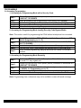
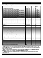
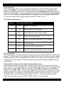
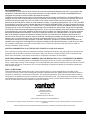
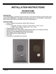
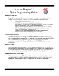
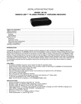
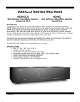
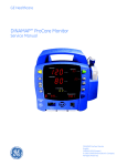
INSTALLATION INSTRUCTIONS DCH4 Doorbell Communicator Hub DESCRIPTION The DCH4 is a Doorbell Communicator Hub that provides keyless entry control with the MRC88CTL. The DCH4 has the ability to answer and open up to 4 doors or gates from the nearest phone. When combined with the DPC100 and MRC88CTL, the DCH4 can provide 2 different door chimes and whole-house paging. SPECIFICATIONS Power: 120VAC/13.8VAC 1.25Amp, UL listed adaptor provided. Dimensions: 210mm x 159mm x 45mm (8.25” x 6.25” x 1.75”) Shipping Weight: 1.5 kg (3.2 lbs) Environmental: 0C to 32C (32F to 90F) with 5% to 95% non-condensing humidity. Ring Output: 8 REN, capable of ringing (16) 0.5 REN phones REN: 0.1A Relay Contacts: 5A @ 30VDC/250VAC Connections: (30) cage clamp screw terminals Talk Battery: 40 VDC 08905107C -1- 1. 2. 3. 4. 5. 6. Power supply connection. Be sure to use the included power supply only. C.O. / Phone Line Input. If installing without a C.O. line, “*5” must be programmed. Entry Phone Input. Line Out to Phones. Can be connected to an unused line / trunk input on a phone system. Door Strike, Relay Contact Output. N.O., COM, N.O. Doorbell Switch / Auxiliary Input. Connect to a doorbell switch (lighted or non-lighted) momentary SPST 6-16V bulb. Note: Unit must be in Doorbell Mode (DIP switch 1 ON). Or uses as an Auxiliary Input, allowing connection to a momentary SPST switch, keyed switch, postal lock with limit switch, etc. Note: Unit must be in Auxiliary Contact Mode DIP switch 1 must be off. 7. Auxiliary Relay Contact Output. N.C., COM, N.O. APPLICATION Note: DIP switch 2 must be ‘on’ (DPC100), DIP switch 1 must be ‘off’ (DCH4) Note: To provide unique front and back door chimes, the DCH4 must have the AUXILIARY contact programmed for “Entry Phone Triggered Rind Cadence Activation” (3#60). See Programming Section B Quick Programming Features. 08905107C -2- PROGRAMMING A. Accessing Programming 1. Accessing the Programming Mode with a Security Code Step 1. Step 2. Step 3. Step 4. Step 5. Come off-hook with any house phone (device) connected to terminals 4 & 5, LINE OUT TO PHONES. Enter *# followed by the 6-digit security code (factory set to 845464). A double beep will indicate that you have accessed the programming mode. You can now Touch Tone program the features listed in section B below. When finished programming, hang up. 2. Accessing the Programming Mode Locally (Security Code Bypass Mode) Note: This mode is useful for programming the DCH4 without a telephone line connected. Step 1. Step 2. Step 3. Step 4. Step 5. Move DIP switch 2 from OFF to ON (Security Code Bypass Mode, see DIP Switch Programming section D). Come off-hook with any house phone connected to terminals 4 & 5, LINE OUT TO PHONES A double beep will indicate that you have accessed the programming mode. You can now Touch Tone program the features listed in section B below. When finished programming, hang up and move DIP switch 2 to the OFF position. 3. Accessing the Programming Mode Remotely Step 1. Step 2. Step 3. Step 4. Step 5. Call into the DCH4 from a Touch Tone phone. Note: Call in from another line to avoid C.O. busy signals, etc. Answer the call from any house phone (device) connected to terminals 4 & 5, LINE OUT TO PHONES. From either phone enter *# followed by the six digit security code (factory set to 845464, see Programming section C). A double beep will indicate that you have accessed the programming mode. You can now Touch Tone program the features listed in section B below. Note: Programming from a cell-phone may not be suitable in areas with weak coverage. 08905107C -3- B. Quick Programming Features Privacy Number (factory disabled) Entry phone 1 keyless entry codes (factory disabled) * Entry phone 1 one time use keyless entry codes (factory disabled) Entry phone 2 keyless entry codes (factory disabled) * Entry phone 2 one time use keyless entry codes (factory disabled) Entry phone 3 keyless entry codes (factory disabled) * Entry phone 3 one time use keyless entry codes (factory disabled) Entry phone 4 keyless entry codes (factory disabled) * Entry phone 4 one time use keyless entry codes (factory disabled) Master keyless entry codes (factory disabled) * Master one time use keyless entry codes (factory disabled) Doorstrike 1 activation time (.5 - 99 secs, factory set to 00 = .5 secs) Doorstrike 2 activation time (.5 - 99 secs, factory set to 00 = .5 secs) Doorstrike 3 activation time (.5 - 99 secs, factory set to 00 = .5 secs) Doorstrike 4 activation time (.5 - 99 secs, factory set to 00 = .5 secs) ** Auxiliary Contacts: Auxiliary contact timing (.5 - 99 secs, factory set to 00 = .5 secs, DIP switch 1 off) 1. Entry phone triggered timed activation (factory setting, DIP switch 1 off) 2. Entry phone triggered continuous activation 3. Entry phone triggered ring cadence activation 4. Auxiliary input triggered timed activation Maximum entry phone ring count (1 - 99 rings, factory set to 5 rings) Enable entry phone ringing (factory setting) *** Disable entry phone ringing Security code (factory set 845464) Enable entry phone Caller ID (factory setting) Disable entry phone Caller ID Entry phone calls give custom double ring cadence (factory setting) Entry phone calls give standard ring cadence Dial “9” to access an outside line Instant outside line access (factory setting, for use with private dial tone) Enable doorstrike latching commands (factory setting) Disable doorstrike latching commands Enable entry phone identifier beeps (factory setting) Disable entry phone identifier beeps Reset all programming to factory default settings Memory Location #00 #11 - #16 *#11 - *#16 #21 - #26 *#21 - *#26 #31 - #36 *#31 - *#36 #41 - #46 *#41 - *#46 #51 - #56 *#51 - *#56 #19 #29 #39 #49 Enter Digits 0-6 digits (0-9) 4-6 digits (0-9) 4-6 digits (0-9) 4-6 digits (0-9) 4-6 digits (0-9) 4-6 digits (0-9) 4-6 digits (0-9) 4-6 digits (0-9) 4-6 digits (0-9) 4-6 digits (0-9) 4-6 digits (0-9) 2 digits (00-99) 2 digits (00-99) 2 digits (00-99) 2 digits (00-99) - then + + + + + + + + + + + + + + + 2 digits (00-99) + #59 1 2 3 4 2 digits (01-99) 1 0 6 digits (0-9) *1 *2 *3 *4 *5 + + + + + + + + #60 #60 #60 #60 #61 #62 #62 #47 *6 *7 *8 *9 *0 ### * Note: A keyless entry code can be programmed for EITHER an unlimited number of uses or one time use, NOT both. There can be a maximum of 6 keyless entry codes and/or one time use keyless entry codes per entrance. ** Note: Auxiliary contact programming is only to be used if the DCH4 is in the Auxiliary Contact Mode (DIP switch 1 OFF), see DIP Switch Programming section D. *** Note: Only entry phone call waiting Caller ID will function in this mode, standard entry phone Caller ID will not. 08905107C -4- C. Security Code This six digit number can be used to access the programming mode. The security code has been factory set to 845464. It is recommended that you change the security code to a personal 6 digit number. To change the security code, access programming (see Programming section A). Enter six digits 0-9 followed by #47. If you have forgotten your security code, follow the steps in Programming section A, 2. Accessing the Programming Mode Locally (Security Code Bypass Mode). Note: The security code must be six digits in length and can NOT contain a * or #. D. DIP Switch Programming SWITCH POSITION DESCRIPTION 1 OFF Auxiliary Contact Mode. 1 ON Doorbell Mode (Factory setting). 2 OFF Normal Operation Mode (Factory setting). 2 ON Security Code Bypass Mode. 3 OFF Entry Phone automatic disconnect (CPC) disabled. 3 ON Entry Phone automatic disconnect (CPC) enabled (Factory setting). 4 OFF Entry Phone busy signal disabled. 4 ON Entry Phone busy signal enabled (Factory setting). E. Privacy Number The “Privacy Number” is factory disabled so an entry phone off-hook will automatically ring the house phones. If a “Privacy Number” is programmed, the visitor must Touch Tone dial the number to be able to call into the house. The “Privacy Number” may be from 1 to 6 digits and is stored in location “#00”. To disable the “Privacy Number,” clear the number’s memory location by entering “#00” without any previous digits. F. Keyless Entry Codes and One Time Use Keyless Entry Codes Each entry phone may have a combination of up to 6 keyless entry codes or one time use keyless entry codes for Touch Tone keyless entry. The keyless entry codes may be from 4 to 6 digits in length and are stored in locations #11 - #16 for entry phone 1, #21 - #26 for entry phone 2, #31 - #36 for entry phone 3, and #41 - #46 for entry phone 4. Up to 6 master keyless entry codes may be from 4 to 6 digits in length and are stored in locations #51 - #56. The master keyless entry codes can be used at any entry phone. To change any of the keyless entry codes to one time use, insert a * in front of the specific memory location during programming (ie: “*#11”). To clear any keyless entry codes, simply enter the location number (ie: “#11” or “*#11”) without any previous digits. 08905107C -5- G. Door Strike Activation Time A single pole double throw relay is available for each entry phone (a second set of contacts are available on solder pads only), and each may be programmed with its own “doorstrike” activation time (programmed in seconds). Each time must be 2 digits (Example: 00 = 1/2 sec.) and is stored in locations #19, #29, #39 and #49 for relays 1 through 4 respectively. All activation times are factory set to 00 (1/2 sec.) Note: A buzz sound will be heard in the house phone and entry phone, indicating the door strike relay has been activated and visitors can now open the door. H. Caller ID The DCH4 is factory set to send “Caller ID” and “Call Waiting Caller ID” information from the entry phones. If “Caller ID” is not required, enter “*2” while in programming to disable the DCH4 from sending “Caller ID” and “Call Waiting Caller ID” data to the house phones. Enter “*1” to enable “Caller ID” and “Call Waiting Caller ID” data (see Operation section A). I. Entry Phone Ring Cadence Entry phone calls are factory set to ring the house phones in a custom double ring cadence (.7 seconds on/.3 seconds off/.7 seconds on then 4 seconds off between rings), “*3”. The DCH4 can be programmed to give a standard ring cadence for entry phone calls (2 seconds of ring, and 4 seconds off between rings), enter “*4” when in programming. Entry phone ringing can also be disabled by entering “0#62”. This is useful when connecting the DCH4 to the DPC100 to provide unique front and back door chimes. J. Outside Line Access 1. Dial “9” to Access the Outside Line - To program the DCH4 for C.O. dial tone, enter “*5” while programming. To gain access to C.O. dial tone, dial a Touch Tone “9”. 2. Instant Outside Line Access (factory default) - To program the DCH4 for private dial tone, enter “*6” while programming. House phones will instantly have the outside line dial tone on an off-hook. K. Maximum Entry Phone Ring Count The number of times an entry phone call will ring the house phones can be limited in programming. The programmable maximum ring count must be 2 digits and is stored in location “#61”. The maximum ring count is programmable from 1 - 99 and factory set to (05) 5 rings. L. Doorbell Switch Input and Auxiliary Contact Output 1. Doorbell Mode (DIP Switch 1 ON - factory setting) With the DCH4 in the doorbell mode (DIP switch 1 ON), a normally open switch (SPST 6-16V lighted or non-lighted doorbell button, etc.) can be connected to terminals 26 and 27 (DOORBELL SWITCH / AUX INPUT). This switch should be located near entry phone 1. Door chime power (normally connected to a doorbell button) can be routed through terminals 28 and 29 (N.O. AUX CONTACT OUTPUT). A momentary closure on the DCH4 input terminals will momentarily activate the AUX CONTACT OUTPUT terminals for the same duration, activating your door chime. Entry phone 1 will be called, automatically answer (see the Technical Practice for your entry phone) and begin ringing the house phones (terminals 4 and 5 LINE OUT TO PHONES). The house phones can then be answered, doorstrike commands entered, etc. (see Operation sections A-E). Notes: Entry phone 1 ringing the house phones can be disabled in this doorbell mode, if it is desirable to have the doorbell chime but not the house phones ring. This option can only be used if 08905107C -6- there is only one entry phone on the DCH4. Program the DCH4 with “0#62 ”(disable entry phone ringing). When the doorbell chimes, picking up a house phone will instantly connect the house phone to the entry phone. If the user presses the doorbell switch again while their call is either ringing the house phones or while talking to the house, the auxiliary relay will activate each time they press the doorbell switch (causing the doorbell to chime again). With the DCH4 in the auxiliary contact mode (DIP switch 1 OFF), the auxiliary contact output can be programmed (see Programming section B) to activate in 3 different patterns when entry phones 1-4 are off-hook. These patterns include a momentary activation, a continuous activation while the entry phone is in use, and a ring cadence pattern. A fourth programmed setting is also available for a timed activation of the auxiliary relay from a contact closure. 2. Auxiliary Contact Mode (DIP Switch 1 OFF) a. Entry Phone Triggered Timed Activation (0.5 second factory default with DIP switch 1 OFF) With the entry phone triggered timed activation programmed (1 followed by #60), when any entry phone is activated, the auxiliary contacts will activate for the programmed time (0.5 99 seconds) in memory location #59 (see section M below). b. Entry Phone Triggered Continuous Activation With the entry phone triggered continuous activation programmed (2 followed by #60), when any entry phone is activated, the auxiliary contacts will activate continuously (latch) until the entry phone disconnects. This is ideal for controlling video cameras, lights, etc. In this mode only, when a house phone has dialed a monitor command (#1, #2, #3 or #4) to connect to an entry phone, the DCH4 will latch the auxiliary relay during the “monitor” once the entry phone answers (so a camera or light can be activated while monitoring. c. Entry Phone Triggered Ring Cadence Activation With the entry phone triggered ring cadence activation programmed (3 followed by #60), when entry phone 1 is activated, a repeating 1 second on and 3 seconds off auxiliary contact pattern is generated. When entry phone 2, 3, or 4 is activated, a repeating double burst contact pattern is generated with 3 seconds off between patterns. The auxiliary contact pattern stops when the house phone answers the call from the entry phone. This is ideal for controlling visual ring indicators, or connecting to a model DPC100 for unique front and back door chimes. d. Auxiliary Input Triggered Timed Activation With the auxiliary input triggered timed activation programmed (4 followed by #60), a momentary contact closure on the DOORBELL/AUX INPUT will activate the auxiliary contacts for the programmed time (0.5 - 99 seconds in memory location #59, see section M below). The auxiliary contacts may be used to provide an additional relay or may be used to add doorstrike entry to an entry phone that does not have a Touch Tone keypad. The auxiliary input contacts may also be used for timed operation of other devices such as yard lights, etc. and can be triggered by the second set of door entry contacts (available through solder pads on the DCH4 PCB). M. Auxiliary Contact Timing To program the length of time the “AUXILIARY CONTACT” is activated when triggered from an entry phone or the “AUX INPUT”, enter 00 - 99 followed by #59. 08905107C -7- OPERATION A. Visitors When a visitor presses the call button (comes off-hook) on the entry phone, the DCH4 will begin ringing the house phones and “Caller ID” information is sent. If a house phone is on a C.O. call, call waiting tones and “Call Waiting Caller ID” information is sent. A Touch Tone “#” from the house phone will put the C.O. call on hold and connect the house phone to the entry phone (beeps will be heard, indicating which entry phone you are connected to). Enter Touch Tones “**” to momentarily activate that entry phone doorstrike and return to the C.O. call or enter “#” to just return to the C.O. call without activating the doorstrike. If the doorstrike is activated, a buzz sound will be heard confirming the strike has been activated. If you require the door strike to remain on continuously (ie: a truck delivery), enter Touch Tones “*1” to continuously activate that relay and return to the C.O. call. A 5 second buzz sound will indicate the door strike relay is latched on. When the visitor calls in again (ie: they are finished unloading the truck), enter Touch Tones “*0” to deactivate the relay. Alternatively, the doorstrike relay can be de-activated by going off-hook with any house phone and entering #1*0 for doorstrike relay 1, #2*0 for doorstrike relay 2, etc. See Operation section C. A short buzz will indicate the door strike relay is off. Entry Phone Caller ID and Call Waiting ID 1 2 3 4 “Entry Phone 1” “Entry Phone 2” “Entry Phone 3” “Entry Phone 4” B. Monitoring Tenants may dial out to an entry phone that supports auto-answering capability by dialing “#1”, “#2”, “#3” or “#4” to call entry phones 1-4 respectively. C. Activating Doorstrike/Gate You may activate the doorstrike relay without calling out to the entry phone. Refer to the chart at the right for dialing strings. When you momentarily activate a doorstrike relay, it will activate for the amount of time specified in Programming, section F. * Note: The latch command can be disabled (see Programming section B). Entry Relay 1 2 3 4 08905107C Momentarily Activate Doorstrike #1** #2** #3** #4** * Latch Doorstrike #1*1 #2*1 #3*1 #4*1 Un-Latch Doorstrike #1*0 #2*0 #3*0 #4*0 Toggle Doorstrike Relay #1*# #2*# #3*# #4*# -8- D. Privacy Number The privacy number feature is useful for preventing unwanted (prank) entry phone calls from visitors. If a privacy number has been programmed, an off hook entry phone is given 4 seconds of dial tone to allow the visitor to enter the privacy number. If the visitor enters the correct privacy number, the DCH4 will ring the house phones. If they enter an incorrect number, they will be disconnected. If a privacy number is not programmed, then an off-hook entry phone will immediately ring the house phones. Note: The “Privacy Number” may be programmed with the first 6 digits of the actual home/office phone number. Visitors may dial the actual 7-digit phone number as if they are making an actual telephone call to the home/office. E. Keyless Entry Codes and One Time Use Keyless Entry Codes Touch Tone keyless entry codes may be used by the tenants to provide keyless entry. Each entry phone may have up to 6 keyless entry codes. There are also up to 6 master keyless entry codes which can be used at all four entry locations. If a keyless entry code has been programmed, an offhook entry phone is given 4 seconds of dial tone before ringing the house phone. During this time a Touch Tone “#” + the “keyless entry code” may be entered. A correct keyless entry code will provide a timed doorstrike activation for that entry phone location. One time use keyless entry codes function as described above but can only be used ONCE. After the one time use keyless entry code has been used, it is instantly cleared from the DCH4’s memory. This is ideal for issuing keyless entry codes to service personnel, etc. Note: A short buzz sound indicates when the relay has been activated and the visitor can now open the door. F. Operation Commands Activate doorstrike relay Continuously activate (latch) doorstrike relay Continuously de-activate (unlatch) doorstrike relay Toggle relay from last position Answer or disconnect an entry phone call Monitor entry phone 1 Monitor entry phone 2 Monitor entry phone 3 Monitor entry phone 4 08905107C Touch Tone Commands ** *1 *0 *# # #1 #2 #3 #4 -9- FCC REQUIREMENTS This equipment complies with Part 68 of the FCC rules and the requirements adopted by the ACTA. On the side of this equipment is a label that contains, among other information, a product identifier in the format US:AAAEQ##TXXXX. If requested, this number must be provided to the telephone company. The REN is used to determine the number of devices that may be connected to a telephone line. Excessive REN's on a telephone line may result in the devices not ringing in response to an incoming call. In most but not all areas, the sum of the REN's should not exceed five (5.0) To be certain of the number of devices that may be connected to a line, as determined by the total REN's, contact the local telephone company. For products approved after July 23, 2001, the REN for this product is part of the product identifier that has the format US:AAAEQ##TXXXX. The digits represented by ## are the REN without a decimal point (e.g., 03 is a REN of 0.3). For earlier products, the REN is separately shown on the label. The plug used to connect this equipment to the premises wiring and telephone network must comply with the applicable FCC Part 68 rules and requirements adopted by the ACTA. If your home has specially wired alarm equipment connected to the telephone line, ensure the installation of this DCH4 does not disable your alarm equipment. If you have questions about what will disable alarm equipment, consult your telephone company or a qualified installer. If the DCH4 causes harm to the telephone network, the telephone company will notify you in advance that –temporary discontinuance of service may be required. But if advance notice isn't practical, the telephone company will notify the customer as soon as possible. Also, you will be advised of your right to file a complaint with the FCC if you believe it is necessary. The telephone company may make changes in its facilities, equipment, operations, or procedures that could affect the operation of the equipment. If this happens, the telephone company will provide advance notice in order for you to make the necessary modifications to maintain uninterrupted service. If trouble is experienced with the DCH4 for repair or warranty information, please contact: XANTECH CORPORATION, 13100 TELFAIR AVE. SYLMAR, CA 91342 (818) 362-0353 If the equipment is causing harm to the telephone network, the telephone company may request that you disconnect the equipment until the problem is resolved. Connection to Party Line Service is subject to State Tariffs. Contact the state public utility commission, public service commission or corporation commission for information. WHEN PROGRAMMING EMERGENCY NUMBERS AND (OR) MAKING TEST CALLS TO EMERGENCY NUMBERS: Remain on the line and briefly explain to the dispatcher the reason for the call. Perform such activities in the off-peak hours, such as early morning or late evenings. It is recommended that the customer install an AC surge arrester in the AC outlet to which this device is connected. This is to avoid damaging the equipment caused by local lightning strikes and other electrical surges. PART 15 LIMITATIONS This equipment has been tested and found to comply with the limits for a Class A digital device, pursuant to Part 15 of the FCC Rules. These limits are designed to provide reasonable protection against harmful interference when the equipment is operated in a commercial environment. This equipment generates, uses, and can radiate radio frequency energy and, if not installed and used in accordance with the instruction manual, may cause harmful interference to radio communications. Operation of this equipment in a residential area is likely to cause harmful interference in which case the user will be required to correct the interference at his own expense. Xantech Corporation 13100 Telfair Avenue, 2/F Sylmar, CA 91342 Installation Instructions, DPC100 © 2007 Xantech Corporation, Document #08905107C This document is copyright protected. No part of this manual may be copied or reproduced in any form without prior written consent from Xantech Corporation. Xantech Corporation shall not be liable for operational, technical, or editorial errors/omissions made in this document. 08905107C - 10 -