1
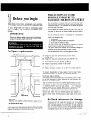
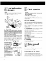
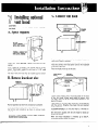
30" EYE-LEVEL&ROWAVE RANGE
30" EYE-LEVELRANGE
ve Ovens, Compactors, Room Air Conditioners, Dehumidifiers, Automatic Washers, Clothes Dryers, Freezers, Refrigerator-Freezers, Ice Makers,Dishwasl
PRECAUTIONS
TO AVOID
POSSIBLE EXPOSURE TO
EXCESSIVE MICROWAVE
ENERGY
II
Before you begin
Do not attempt
to operate this oven with the door open
since open-door
operation
can result in harmful exposure to
microwave
energy. It is important
not to defeat or tamper
with the safety interlocks.
Read these instructions
completely
and carefully.
If followed, they will simplify the installation job.
If your range does not have a microwave upper
oven, disregard the following
microwave
information.
Do not place any
the door or allow
sealing surfaces.
IMPORTANT:
object between
soil or cleaner
the oven front face and
residue to accumulate
on
Do not operate the oven if it is damaged.
It is particularly
important
that the oven door close properly
and that
there is no damage to the:
1. Door (bent)
2. Hinges and latches (broken or loosened)
3. Door seals and sealing surfaces.
Observe all governing codes and ordinances.
Failure to follow these instructions
could lead
to fire or electrical shock hazard.
The oven should
not be adjusted or repaired
except properly
qualified
service personnel.
The oven should
be checked
qualified
service personnel after
A. Spacerequirements
/
\
==lrll_i-i==
Do not operate
Height
7l-7/8”
for range with
min.
eye-level
oven plus vent hood:
B=
Height
for range with
eye-level
oven alone:
C=
Width
between
D=
Height
of countertop:
30-318”
35.5/8”
receptacle
location:
7” max. from floor.
-I] L
1-aIII
L
/’
I
min.
to 30-l/2”.
to 36.13/16”.
discoloration
at least l/2”
8”
to 22”
from
either
of base cabinet,
front of oven
beyond front surface of cabinets.
cabinet,
frame
Do not seal range to cabinets.
The copper power cord (pigtail)
to the wall receptacle
to avoid
portion of the range and wall.
\
A
66-l/8”
22-112”.
F= Pigtail
To prevent
must extend
by
glass is broken.
A=
E= Depth:
--
for microwave
leakage
a repair is made.
the oven if the door
counters:
by anyone
must run downward,
pinching
the cord
left or right
between rear
B
d
go0
! P
/
Top of eye-level
oven may be installed
against bottom
of overhead cabinet.
However,
for easy installation
and removal,
allow
1” clearance
between
oven top and cabinet.
or 1” clearance
between
hood top and cabinet. When hood is attached
to cabinet, allow 1” clearance between hood bottom and oven top.
t-F-
WALL
RECEPTACLE
I
7”
MAX.
The back of a free-standing
range may be installed
against a
vertical
wall. Sides may be installed
against base cabinets
or
against vertical
walls extending
above upper edge of the cook
top.
t
CAUTION:
Reaching
over heated surface elements
causes risk I-If
_.
being burned. To eliminate
hazard, cabinets should NOT
be installed above range.
If cabinets
are already provided,
reduce hazard
ling a range hood. Hood should project horizontally
bottom of cabinets by a minimum
of 5 inches.
by instalbeyond
B.Check microwavefor damage
Remove all packing material
from the oven cavity.
When
unpacking
the unit, check for damage such as misaligned
door, damaged gaskets around the door, or dents inside the
oven or on the exterior.
If there is any damage, please do
not operate the unit until it has been checked by an authorized Whirlpool
trained service technician.
C. Electrical requirements
Wire size and connectors
must conform to
the ampere rating of the range as stated in
paragraph C-l.
IMPORTANT:
Attach special ring connectors to the aluminum
house wiring that are UL listed and designed
for joining copper to aluminum. These special
ring connectors (available at electrical supply
houses) can be attached directly to the range
terminal block.
SAVE THESE INSTRUCTIONS
FOR THE
LOCAL ELECTRICAL INSPECTOR’S USE
WARNING: DO NOT PLUG THE “PIGTAIL”
POWER
CORD
INTO A LIVE WALL
RECEPTACLE
BEFORE
CORD
IS
PERMANENTLY
CONNECTED
TO THE
TERMINAL BLOCK.
1. This appliance must be connected to the proper
electrical voltage and frequency as specified on
nameplate. Models rated at 15 KW on 240 volts
(11.25 KW on 208 V) or more require a separate 50
ampere circuit. Models rated less than 15 KW on 240
volts (11.25 KW on 208 V) require a separate 40
ampere circuit. Fuse both sides of the line. DO NOT
fuse the neutral. A time-delay fuse or circuit breaker
is recommended. Wire sizes must conform to the
requirements of the National Electrical Code and/or
local codes and ordinances for the kilowatt rating of
the range. The nameplate is located on the front
frame of the main oven behind the main door. For
the Eye-level Microwave, it is on the front frame
behind microwave oven door.
2. All wires ending at the appliance
ring type terminals.
must terminate
3. All power cords and cables to appliance
fitted with a UL approved strain relief.
in
must be
4. The range should be connected with copper wire
only. Aluminum wire requires special connectors.
Improper use may create a fire hazard.
5. Appliance may be connected directly to the fused
disconnect (or circuit breaker) box through flexible
armored or non-metallic sheathed copper cable. Do
not use an extension cord. Allow 4 feet (min.) slack
so appliance can be moved for servicing. Wire sizes
must conform to the ampere rating of the range. See
paragraph C-l above.
The connectors must conform to the ampere
rating of the range as stated in paragraph C-l.
7. If local codes permit, your range may be connected
with a three wire flexible type, UL listed “pigtail”
power cord of the proper ampere rating.* Plug must
match a 3-wire NEMA type lo-50R receptacle
(shown below).
8. CAUTION: FOR MOBILE HOME USE, A 4-WIRE
POWER CORD MUST BE USED. This appliance is
manufactured with ground connected to frame. This
must be revised so green ground wire of 4-wire
power cord is connected to frame.
If using a 4-wire NEMA type
(shown above) you must use a
listed “pigtail” power cord. Cord
or SRDT, at least 4 feet long
ending in ring terminals at the
14-50R receptacle
matching 4-wire UL
should be type SRD
with all conductors
appliance.
MINIMUM CONDUCTOR SIZE. . .
(4-WIRE COPPER POWER CORD)
For 40 ampere circuits: two No. 8 conductors, one
No. 10 white neutral, and one No. 8 green ground.
For 50 ampere circuits: two No. 6 conductors,
No. 8 neutral and one No. 6 green ground.
one
*CAUTION:
Power Cord Requirements
- Only a
power supply cord kit rated at 240 volts, 50 amperes
and investigated for use with ranges shall be used.
6. WARNING: THE TERMINAL
BLOCK ON THE
APPLIANCE ACCEPTS COPPER WIRE ONLY,
NOT ALUMINUM. IF ALUMINUM HOUSE WIRING
MUST BE CONNECTED,
USE ONE OF THE
FOLLOWING PROCEDURES:
l
l
Connect copper wire to the range terminal block
(using ring terminals).
Connect the copper wire to the aluminum house
wiring using special connectors UL listed and
designed for joining copper to aluminum.
3
Begin the
installation
Begin electrical
connection
Remove racks and all other contents from oven
before moving appliance. Be sure to remove all
packaging material (cardboard,
protective film,
etc.) from range before use.
A. Remove shipping skid
Grounding
Instructions
WARNING:
THIS APPLIANCE MUST BE CONNECTED TO A
GROUNDED,
METALLIC,
PERMANENT
WIRING
SYSTEM, OR AN EQUIPMENT GROUNDING CONDUCTOR SHOULD BE RUN WITH THE CIRCUIT
CONDUCTORS AND CONNECTED TO THE EQUIPMENT GROUNDING TERMINAL OR LEAD ON THE
APPLIANCE.
.m..CARDBOARDPADS
UNDER APPLIANCE
SHIPPING iKID
\
,.
Remove the 4 cardboard pads from shipping box. Place
them on floor as shown to protect appliance’s finish.
Rest appliance (on its back) on pads.
CAUTION: Before connecting flexible armored cable
for permanent wiring, disconnect power at fuse box or
circuit breaker.
A. Remove terminal block cover
Remove the two 318” shipping bolts from wooden skid.
Discard the skid.
B. Extend leveling legs
3/8”
BRASS NUTS
TERMINAL
BLOCK ,
COVER
ADJUSTABLE WRENCH
BOTTOM OF
LEVELING LEG
Terminal block cover is located on back of the appliance near the bottom.
Remove retaining screws to expose electrical terminal
block.
Once skid is removed, 4 leveling legs are exposed at
bottom of frame.
Loosen legs by applying an adjustable wrench to the
1%” base of the leveling legs. Back each of them out
about 4 complete turns.
Stand appliance
on its base.
USE ONLY the supplied 3/8” brass nuts when connecting cord.
USE ONLY ring type terminals
to connect cord.
3
B. Strain relief required
LOCKING
,
Use this wiring method ONLY if local codes permit
connecting
frame grounding
conductor to neutral
wire of power cord.
THIS APPLIANCE
IS MANUFACTURED
WITH
NEUTRAL
TERMINAL
CONNECTED
TO THE
FRAME.
If local codes do not permit grounding through the
neutral. The 3-conductor
cord or cable assembly
must be replaced by a 4-conductor
cord. The
replacement
cord must be rated 240 volts, 50
amperes and investigated
for use with ranges.
II
1. Connect
terminal.
INSERT FROM
UNDER FRAME
neutral wire to the center silver-colored
2. Connect remaining 2 wires to the terminals on either
side of the silver colored terminal.
Disconnect clamping ring from strain relief. Push relief
(from bottom) through hole beneath terminal block.
Tighten clamping ring (from above) onto strain relief
threads.
--L-n-U
-I--Y.-wW-m
_--,.- is*~l--T-i+..4 ,_.~.,,.
3. Use ring type terminals only. Connect with the brass
nuts that are taped to the frame. Do not loosen factory installed nuts already on the terminal.
4. Replace terminal block cover.
D. 4-wire electrical connections
SILVER COLORED.
TERMINAL
i
RUN CORD THROUGH
STRAIN RELIEF
Run cord or cable through
strain relief.
Leave enough slack to attach ring-type terminals
terminal block. Tighten clamping screws.
C. If frame grounding is allowed
to
y
I”’
RELIEF
:
SILVER COLORED
Use this wiring method for mobile homes
whenever a 4-wire installation
is required.
and
1. Remove the grounding strap screw from the range
frame. Keep this ground screw. Bend up the grounding strap so that it does not contact the range frame.
2. Connect the green ground wire to the frame of the
appliance with the ground screw, using the hole in
the frame where the ground strap was removed.
NEUTliAIv
1’ ’
3. Connect the white neutral wire of the power cord to
the silver colored terminal of the terminal block. Connect the remaining wires to the outer terminals.
4. Replace the terminal
block cover.
5
/A 1 Level and position
” the range
Gl
NOTE:
If installing the option vent hood, go to that step now.
Instructions are on page 7. Level and position the
range after the vent hood is attached.
‘-
I
SPIRIT
LEVEL -\
5
Check operation
CAUTION:
Do not touch any heating
and you may be burned.
elements.
They
may
be hot
A. Surface elements
Turn on each of the 4 surface elements.
Check
tain they heat and check for proper operation
indicator
light(s).
to be cerof surface
B. Oven elements
BAKE - Set selector switch on BAKE. Turn thermostat
to
350°
BAKE. The bottom
element should glow red and indicator
light should
be on. The upper element
should
become hot but NOT glow red.
BROIL
- Set selector switch on BROIL.
Turn thermostat
to high. The top element should glow red and indicator
light should be on.
C. Rotisserie
(if optional
A. Leveling
Move range into fiGI operating position. Use caution
when moving this appliance to prevent damage to floor
coverings. The weight of the appliance may cause ripping, scratching or other damage to the floor. For best
results, slide appliance onto cardboard or hardboard
before moving to prevent damage.
Place rack in oven. Put spirit level on rack. If range
needs leveling, remove oven drawer. The tops of leveling legs will be exposed as shown.
Use a 3/” allen wrench to raise or lower legs as needed.
IMPORTANT:
Oven must be properly leveled for
satisfactory baking conditions.
B. Remove shipping clips
Each of the 4 elements is
secured by a shipping clip.
Place straight
Place broiler
Back appliance away from
wall, leaving room to make
connection.
Plug flexible
pigtail into ap-
proved receptacle (if allowed by local codes). OR
Connect flexible armored or
non-metallic shielded cable
directly to fused disconnect
box.
6
oven rack on bottom
kit is installed)
ledge position
pan on oven rack
Place special rotisserie
rack on broiler
bar on this special rack.
Rotation
should start
tacle in back of oven.
D. Clock
when
pan. Position
spit bar is inserted
the spit
into
recep-
(if so equipped)
Refer to operating
instructions
(packed in the oven).
in the Use and Care Guide
E. Cleaning
See the Use and Care Guide (packed
care and cleaning instructions.
in the oven)
for proper
Before you call
for service. . .
Using screwdriver or pliers,
bend upper part of the clip
to vertical position. Slide
clip out and discard it.
C. Complete elect.rical connection
rotisserie
See the Use and Care Guide
Be sure pigtail
Check
power
for blown
cord
for trouble-shooting
is plugged
fuses or tripped
checklist.
in.
circuit
breaker.
If you must call for service.. .
You will
need the appliance
model
and serial number.
Find the serial plate on the front frame of the main
behind the main door. For the Eye-level
Microwave,
on the front frame behind the microwave
oven door.
oven
it is
7
Ll
Installing optional
vent hood
C. Connect vent hood
CAUTION:
Disconnect
vent hood.
from
electrical
supply
before
installing
A. Spacerequired
EYE-LEVEL
RANGE
Reach through hole in bottom
cord until all slack is removed.
Install
vent
nection.
hood
BEFORE
making
When measuring,
remember
justed. Total height needed
final
that leveling
for vent hood
electrical
con-
legs will be adis 71-7/e”
with
of vent hood,
pull out power
Place vent hood on the top of the oven. Lift front of vent
hood and connect vent hood power cord to the receptacle
in the top of the oven.
Rest vent hood on the top of the oven.
legs extended about half way.
The top of the vent hood
of over head cabinets.
may be installed
against
bottom
VENT HOOD
BACK
\
B. Removeknockout plug
ORIGINAL
,/POSITION
\
I
REMOVE
IT
THIS POSITION
i
OVEN
BACK
Loosen screws holding
the 2 mounting
plates on the back
of the vent hood.
Rotate
these plates (as shown)
until
the lower holes line up with matching
screwholes
in the
Position
Knockout
appliance
so that front
plug is at right
Use hammer
out plug.
and back are accessible.
rear of oven top panel.
and screwdriver
as shown
to remove
CAUTION:
Avoid damage to power supply
located below knockout plug.
knock-
receptacle
Fasten plates to the oven back using the 2 screws supplied
with the vent kit. Retighten
the screws that were loosened
in the vent hood.
To connect ducting
stallation,
or to use vent
see instructions
packed
See instructions
packed
proper use and care.
When
“Level
vent hood
and position
with
hood
with
the vent
in a ductless inthe vent hood.
hood
installation
is finished,
range” on page 6.
for details
go to
on
Step 4,
HOME 5% APPLIANCES
Making your world a little easier.
In the event your WHIRLPOOL
appliance should need service, call the dealer from whom you purchased the
service company. He is in the Yellow Pages of your telephone
appliance or a WHIRLPOOL franchised TECH-CARE@
directory listed under “Appliances-Household-Major-Service
and Repair.” You can also obtain his name and number
by dialing, free. the Whirlpool COOL-LINE”
service (SW) 2551301.
Dial just as ou normally dial long distance. A
special operator will tell you the name and number of your nearest Whirlpool TE 8 H-CARE@ service outlet. During
normal working hours,, Whirlpool consultants at this same number will also answer any questions about operating or
maintaining your appltance not covered in your Use and Care Guide.
Learn the benefits of using TECH-CARE
WHIRLPOOL
appliance.
Part No. 313480
Rev. 6
service
for maintaining
the quality originally
built into your
Printed
in U.S.A.
idifiers, Automatic Washers, Clothes Dryers, Freezers, Refrigerator-Freezers, Ice Makers, Dishwashers, Built-In Ovens and Surface Units, Ranges, Microv