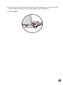
1
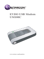
EVDO USB Modem UM100C www.utstar.com/handsets CONTENTS CONTENTS 1. BEFORE USING UM100C ................................................................................1 1.1 About this User’s Manual ..........................................................................................1 1.2 Product Overview ......................................................................................................1 1.3 Product Package Contents .......................................................................................1 1.4 Introduction to UM100C USB Modem......................................................................2 1.5 Product Features .......................................................................................................2 1.6 Product Handling .......................................................................................................2 1.7 Configuration .............................................................................................................3 2. INSTALLATION AND SETUP FOR QUICKLINK MOBILE.............................3 2.1 QuickLink Mobile Setup Program .............................................................................4 2.2 QuickLink Mobile Setup Wizard................................................................................6 3. USING QUICKLINK MOBILE ...........................................................................8 3.1 Features .....................................................................................................................8 3.2 Getting Started...........................................................................................................8 3.3 Connecting.................................................................................................................9 3.4 SMS Messaging ...................................................................................................... 11 4. QUICKLINK MOBILE PREFERENCES .........................................................13 4.1 General Preferences ...............................................................................................13 4.2 WWAN Specific Settings.........................................................................................14 4.3 SMS Settings ...........................................................................................................17 4.4 Additional Features..................................................................................................18 5. INSTALLING UM100C .....................................................................................22 5.1 Precautions ..............................................................................................................22 5.2 Recommended System Requirements ..................................................................22 5.3 Installing Software ...................................................................................................23 6. REGULATORY AND SAFETY INFORMATION.............................................30 6.1 Regulatory Notices ..................................................................................................30 6.2 Operating Conditions...............................................................................................30 6.3 Warnings and Cautions ...........................................................................................30 6.4 Safety Precautions ..................................................................................................31 6.5 Specific Absorption Rates (SAR) ............................................................................32 6.6 Safety Information for FCC RF Exposure ..............................................................33 6.7 General Safety.........................................................................................................33 6.8 FCC Compliance Information .................................................................................34 6.9 Manufacturer's Warranty.......................................................................................34 1. BEFORE USING UM100C 1.1 About this User’s Manual You will find all the information you need to install and use the UM100C in this user’s manual. Before using the UM100C, you must properly install the UM100C by closely following the installation instructions. Instructions • Install the UM100C software before inserting the UM100C USB Device into your PC. The installation software is included in the product package. Insert the CD into your CD-ROM drive. Installation may take a few minutes. • It is highly recommended that you read the safety precautions described in this manual before using the UM100C. 1.2 Product Overview Thank you for purchasing UM100C USB Modem. The UM100C is a 3G wireless device that enables high-speed wireless communication from your PC. The UM100C is simple to install and use. 1.3 Product Package Contents The following items are included in the product package. If any of the items listed below are missing, please contact the retail location where you purchased the product. UM100C Wireless USB Modem Installation CD that contains software and this user manual UM100C Screen Clip USB Modem Extension Y Cable Quick Start Guide 1 1.4 Introduction to UM100C USB Modem The UM100C is designed for your PC’s USB port, which is available in most PC models. The UM100C can be used to access the Internet, your company’s intranet, or you can use it to send and receive email. It is extremely useful when you are away from the office, on the road, or wherever wireline Internet access is not readily available. 1.5 Product Features - Power management: The UM100C utilizes power management and system overhead reduction functions provided by the USB interface for maximum power savings. - Antenna design: Efficient, innovative design optimizes data transfer rate and sensitivity to network signals. - Extension Y Cable connector: Connect the Y cable to two separate USB ports of your computer to deliver sufficient power when needed to increase RF performance, and to solve clearance issues. - USB Modem that supports Type A USB Port interface. - Supports North American PCS (1900 MHz), Cellular (800 MHz) and Aws (Tx 1700MHZ, Rx 2100MHZ) bands. - Utilizes QUALCOMM MSM6800A chip set. - Supports 3G network technologies. - Supports Windows 2000, XP and Vista systems with installed host software and driver. 1.6 Product Handling - Do not put any adhesive label on the USB connector. It may leave a sticky residue that can cause problems inside the PC USB port. - The UM100C USB device should easily slide into the USB port. Do not force the UM100C into the USB port as it may cause damage to the modem and/or the port. - Keep the UM100C in a dry and clean place. (Storage temperature: -22°F to 149°F [- 30°C to 65°C]). Keep your device away from liquids, dust and excessive heat. 2 1.7 Configuration To use the UM100C, you should install the software included in the installation CD and configure the UM100C USB device. See the next section for more information on software installation and USB device configuration. 2. INSTALLATION AND SETUP FOR QUICKLINK MOBILE This section will guide you through the installation and setup process for QuickLink Mobile. Before getting started, you should become familiar with the documentation that came with your USB Modem. CD’s 1. If you purchased a USB Modem, there is only one CD that contains QuickLink Mobile and the USB Modem drivers. Getting Started To install QuickLink Mobile: 1. Turn on your computer then close all applications. 2. Insert the CD-ROM into your CD drive. 3. If set up does not automatically start, click the Start button on the taskbar then choose Run. Type D:\Start (where D is the letter of your CD-ROM drive) then click OK. 4. Follow the steps in the next section. * QuickLink Mobile software must be installed before you insert the USB Modem in to the computer for the first time. Only after the software has been installed can Windows successfully install and configure the USB Modem. 3 2.1 QuickLink Mobile Setup Program STEP 1: The “Welcome” screen appears. Click the “Next” button to continue with the installation process. STEP 2: After the Welcome screen appears, you will see QuickLink Mobile License Agreement. In order to install and use this product you must agree with the terms of this agreement. Select “I agree with this software license agreement”, then click the “Next” button to continue. If you do not agree with this agreement, click the “Cancel” button to exit. STEP 3: You are now ready to select the location on your computer where QuickLink Mobile should be installed. It is recommended that you do not modify the default destination folder. Click the “Next” button to continue. 4 STEP 4: During this step the components of QuickLink Mobile product are being installed onto your computer. Installation will occur to the destination folder specified in Step 3 above. STEP 5: Installation is now complete. Click the “Finish” button to leave the QuickLink Mobile setup program and begin using your new software. * The setup program will automatically create a QuickLink Mobile shortcut on your desktop. 5 2.2 QuickLink Mobile Setup Wizard After you have successfully completed the installation process of QuickLink Mobile, you are ready to start QuickLink Mobile program and begin your initial setup. The steps in the Setup Wizard are critical to the proper operation of QuickLink Mobile. STEP 1: On first-run of QuickLink Mobile the Setup Wizard will automatically run. The “Welcome” screen appears. If you have an Internet connection, it is recommended that you check to see if you are running the latest version of QuickLink Mobile. Click the “Check for Updates” button to perform this check. Click “Next” to continue. STEP 2: USB device users would insert their USB device now, and wait for Windows to detect and install drivers for the device. Note: If the Card has already been activated, the screen above will not appear. You will need to use the “Activate” menu in the connection manager window under Tools> Activation. 6 STEP 3: The detection and configuration process for your wireless device is now complete. In this step you can elect to run QuickLink Mobile automatically every time you start your computer. Click “Finish” when complete. Please familiarize yourself with the information in the “Using QuickLink Mobile” and “Connecting to the Internet” sections of this guide. 7 3. USING QUICKLINK MOBILE Today’s online world offers more services everyday and Wireless gives you the tools you need to take advantage of the best in connectivity solutions. With QuickLink Mobile, enjoy the freedom and convenience of wireless Internet connectivity from your notebook computer! 3.1 Features WWAN (Wireless Wide Area Network, 1xEV-DO/1xRTT/CDMA) Specific Features: • Configures your PC to use your USB Modem. • Creates a Data Connection if using an EVDO capable USB Modem. • Copies utility to create wireless copies of your dial-up connections, if supported by your device. • Test function for WWAN device. * A WWAN capable device is required to use the WWAN features. Individual WWAN features are also device dependent as described in the WWAN section above. Other Features: • Logs connections used, duration and bytes sent and received. • It also supports SMS messaging. • See the section “Additional Features” for more information about the features of QuickLink Mobile. 3.2 Getting Started Double click on the Cricket Wireless icon on your desktop or click on the Windows Start menu and select QuickLink Mobile from the list of Programs. About the Wireless Networks View QuickLink Mobile will open the Wireless Networks window by default. This view is where you manage your wireless connections. The Wireless Networks window displays all currently available network connections. 8 At a glance you can see the signal strength and battery level. Select “Refresh Networks” from the “Tools” menu to update the information in this panel. Your current connection state and the elapsed time of the connection are displayed along the bottom of the status bar. If your expected connection does not appear after starting QuickLink Mobile, select “Refresh Networks” from the “Tools” menu. * If you change USB Modems, you will need to run the Setup Wizard again. To do this, select “Run Wizard” from the “Tools” menu. 3.3 Connecting Once your device is properly configured, connecting to the Internet is as simple as selecting the network connection type shown in the list and clicking the “Networks” button. 1. Select Data Connection. 2. Click the “Connect” button when it becomes enabled. Once connected, the “Connect” button will change to “Disconnect”. Simply click this to end your current connection. To connect to any other network shown, select it, and then select “Connect”. The Status Bar Information regarding your current network connection can be seen in the status bar along the bottom of QuickLink Mobile interface. For more information on this status bar, see the section “The Status Bar” in the “Additional Features” section. * The first time you connect with the Data Connection, a connectivity warning message will appear. You have the option to suppress these warning messages when they are displayed. 9 QuickLink Mobile will display status information at the bottom during the connection process as well as while connected. When not connected, the status text in the lower left corner will display “Not connected” for the currently selected network. The timer will display “00:00:00”. Once connected, the status text will display “Connected” and the elapsed timer will begin to run. The pop up status can be turned off, if desired, by selecting “Options”, “Preferences”, “Options” tab, then un-checking “Show popup status windows by tray”. Right clicking on the tray icon provides various options and double clicking on it will always show the application. Placing your cursor on it will display the current connection status. Based on your preferences, your browser, e-mail or VPN program can be launched automatically, or you can launch whatever software you want to use. At any time during your connection you can check your current connection speed and throughput stats in the Statistics tab of the Session Information window. To see this window, select “Statistics” from the “Session” menu. The Session Information window will also contain a My Computer tab if applicable. The My Computer tab contains detailed information about your computer. This information is helpful when troubleshooting a problem. When using the “Data” connection: By default QuickLink Mobile enables the software for the Data connections. If your connection fails when you try to connect, with QuickLink Mobile returning to its idle state, you should try to connect again. If you feel you may have incorrectly entered your wireless telephone number during initial setup, select “Tools”, then “Run Wizard”. 10 Dormancy: The data session becomes dormant if you are not sending or receiving any data. As soon as you resume sending or receiving data, the data session will return to an active state. Depending on your device and service plan, your data session may disconnect during a dormant state. 3.4 SMS Messaging QuickLink Mobile supports SMS Messaging for the UM100C. Receiving SMS Messages • All of your SMS messages will appear in the list box at the top of the SMS messaging view. By default, all sent and received messages will appear. • To view only certain messages, click on the “View” toolbar button and select “Received Messages,” “Sent Messages” or “All Messages.” • If you are in the SMS Messaging view and a new message arrives, the message will automatically appear in the list formatted in bold. • To view a long SMS message, select the message in the list view. The details of the message will appear below the list. • If you are not in the SMS Messaging view and a new message arrives, a SMS icon will appear in the status bar showing that new messages are available. There is also a SMS preference option that can automatically switch QuickLink Mobile to the SMS view when new messages arrive. By default, this feature is turned off. • To reply to an inbound message, select the message and press the “Reply” button. The phone number of the sender will be populated in the send area below. Enter your new message and press the “Send” button to send the message. 11 • To forward an inbound message, select the message and press “Forward” button. The message will be populated in the send area below prefixed with a “FW:.” Press the “Send” button to send the message. • To resend a sent message, select the message and press the “Resend” button. The phone number and message will be populated in the send area below. Press the “Send” button to send the message again. Sending SMS Messages • While using the UM100C, to send a text message to: — A US-based wireless number, enter: +, 1, then the wireless number. — A wireless number outside the US, enter: +, 011, the country code, then the wireless number. • To send a SMS message to one or more subscribers, enter their 10-digit mobile numbers separated by semi-colons in the “To...” field. (Ex: 555-555-5555; 555-555-5556). • With some devices that support SMS messaging contact lists, you may be able to click on the “ ” button to open your contact list. • The phone number and the message fields are required. • The Character counter counts up from 0 to 160 and counts all of the characters typed in the message field. • Click the “Send” button. 12 4. QUICKLINK MOBILE PREFERENCES 4.1 General Preferences Options Tab Click on “Options”, then “Preferences”. Minimize application into tray: When you minimize the application it will now appear in the Windows task bar. To restore the application click on QuickLink Mobile tray icon, and select “Show Application”. Show popup status windows by tray: Displays small popup sliding windows in the lower right corner of the screen when connections are made, and when network connections are lost. Run QuickLink Mobile at Startup: Automatically launches QuickLink Mobile whenever you start your computer. Updates Tab 13 This feature allows QuickLink Mobile to automatically check for software updates. If an update is available, you will be notified of its size and approximate download times. You will be given the choice to download or cancel. If you select download, a display appears that shows the progress as the update is downloading with the option to cancel if desired. You do not need to download the updates wirelessly; you can use any connection to the Internet. Note: If you download the updates wirelessly, normal usage charges apply. You can allow the software to automatically check for updates, daily, weekly (default), or monthly. It only checks when the application is running and when it detects that you are connected and able to access the Internet. If desired, you can select “Manually” and the software will only check for updates when you select “Update Now” (pictured above), or when you select “Help”, then “Check for Updates” from QuickLink Mobile’s main screen. 4.2 WWAN Specific Settings WWAN Preferences Click on “Options”, then “Preferences”. WWAN Options Set Options . . . : This is used to set various WWAN connection settings. See below. Automatically Connect: If desired, you can select to have QuickLink Mobile automatically connect at application startup. 14 Connect Tab When you select the “Set Options” button from the screen above, the following options will appear (“Options”, “Preferences”, “WWAN tab”, “Set Options. . . “) : Do not open my browser: With this option selected, when you connect to a WWAN network, QuickLink Mobile will not automatically launch your default web browser. Open my browser to my default home page: With this option selected, when you connect to a WWAN network, QuickLink Mobile will automatically launch your default web browser and your home page will load. Open my browser to this URL: With this option selected, when you connect to a WWAN network, QuickLink Mobile will automatically launch your default web browser but do it in such a way that the URL you specify will load instead of your home page. Turn off graphics: If you select this it will turn off graphics in Internet Explorer. With these options off, web pages will load faster but you will have to right click and select “show picture” to view any pictures. Run program on connection: This allows automatically running a program when you , to use QuickLink Mobile to connect to a WWAN network. Select the browse button, browse to the desired application you want to run when you connect to a WWAN network using QuickLink Mobile. The application will run for all WWAN connections made from QuickLink Mobile. 15 VPN Tab The following options exist on the VPN tab (“Options”, “Preferences”, “WWAN” tab, “Set Options. . . “, “VPN” tab) : VPN Client: QuickLink Mobile automatically detects if certain VPN clients like Microsoft, Cisco, CheckPoint, etc are installed on the computer and allows you to select the one you wish to use. Check with your network administrator to setup your VPN connection. If the VPN client you wish to use does not appear in the list, you can select “Other VPN Application”. Other VPN Application: This allows running a VPN program when QuickLink Mobile connects to a network. Enter the full path to an executable, or select the browse button, , to find the path to the desired application. 16 4.3 SMS Settings SMS (Short Text Message Service) is a messaging application for your wireless device which allows you to compose and send text messages to other wireless phones and email accounts. The SMS tab in the preferences dialog allows you to configure certain text message delivery options. These options include: Incoming Message Options • Open SMS window on arrival of new message: Enable/disable automatic opening of the SMS window on arrival of new text messages • Play sound on arrival of new messages: Play a sound upon receipt of new SMS messages Outgoing Message Options • Message delivery duration: Includes settings to automatically resend returned or undelivered messages for a period of time. The default is a duration of 1 week. Confirmations The following confirmation dialogs can be turned on or off: • Warn before deletion of messages. • Confirm deletion of messages. • Confirm sent messages. 17 4.4 Additional Features In addition to the basic features mentioned in previous sections, QuickLink Mobile has the additional features listed below. The Status Bar The details of your current connection can be seen in the status bar at the bottom of QuickLink Mobile interface. This status bar is always visible when the interface is fully expanded. You can see the service area as an icon appearing on the left bottom of the QuickLink Mobile interface. You see a 1X icon when you are in a 1X coverage area, a DO icon when you are in EVDO Rev.0 coverage area, and a rA icon when you are in EVDO Rev.A coverage. Connection Status The text on the status bar reflects your current state. During an active connection, this text will change to “Connected”. If you are not connected, it will display “Not Connected”. WWAN USB Modem Status Area The text can change to the following: • Device not inserted: Your WWAN USB Modem is removed from the laptop. • Device not activated: Your USB Modem needs to be activated. Select “Activation” from the Tools menu. Coverage For USB Modems, an icon will display if you are in Broadband coverage. Hover the mouse to see the tool tip showing the name of the current network. Throughput The amount of data that you have sent and received since the current network connection was initiated can be seen by holding the mouse over the green up and down arrows on the left side of the status bar. Elapsed Time The amount of time that has elapsed since the current network connection was initiated is tracked on the lower left side of the status bar. 18 The Session Menu Connect / Disconnect: You can connect or disconnect the wireless networks. Log: This provides a concise session log of your network activity. Click on a column heading to sort the log. This window also displays the total number of sessions as well as the total time connected. The information displayed in the Usage log can be customized using the controls that appear just below the list. To view only the connection history of a specific network type, check the “Selected connection” checkbox and select the desired type from the drop-down list. To view only the connections made during a specific interval, check the “Date range” checkbox and specify the date in the “From:” and “To:” fields. To export this log as a CSV file, click the Export button that is immediately above the log. To clear the log, press the Clear button. Note that clearing the log cannot be undone. Close: Exit the application. 19 The Tools Menu Test WWAN Device: Retrieve and display detailed information about your WWAN device (1xEV-DO/1xRTT/CDMA USB Modem) such as manufacturer, model, version, etc. This information can be valuable when troubleshooting a problem. Run Wizard: Runs the Setup Wizard again. This is useful if you need to reconfigure QuickLink Mobile to use a new USB Modem. Activation: Programs the activation code, phone number, and IMSI(MIN) to the USB Modem. Data Setup: Please contact the service provider for details. 20 The Options Menu Control Panels: From this menu you have access to your system’s “Modem”, “Network and Dial-Up Connections”, and “Internet” control panels. You can also see all control panels by selecting “All”. Preferences: This is used to select preferences for connection settings. Please see WWAN Specific Settings for details. Always on Top: When checked, QuickLink Mobile window displays in front of all other open application windows, even if another window is placed over QuickLink Mobile Software window. The “Internet” button Launches the default web browser on your computer. The “Email” button Launches the default email application on your computer. The Help Menu The Connection Manager has a Help section. Please see the Help section for additional questions. “Email” Button “Internet” Button 21 5. INSTALLING UM100C 5.1 Precautions 1) Do not insert the UM100C before installing the software on the computer. When you complete the software installation, the system will prompt you to insert the UM100C into the USB port. 2) Once the modem has been inserted into the PC, do not remove it from your PC without first completing the unplugging/ejection process. 5.2 Recommended System Requirements To successfully install and use the UM100C USB device in your PC, the following system specifications are required. Item Required Specification Operating system Windows® Vista / Windows® XP / Windows® 2000 Port Type A USB port Processor 150MHz or faster Disk drive CD-ROM Memory 128 MB Disk space 32 MB Dial-up networking DUN bound to TCP/IP * The UM100C is useful for Pocket PCs that include a USB port. Voice service is not supported. 22 5.3 Installing Software 5.3.1 Warnings • Make sure to complete the unplugging/ejection process before removing the UM100C. If you remove the device improperly, the product may be damaged. • Before inserting the UM100C into your PC’s USB port, remove the Installation CD from the CD-ROM drive. 5.3.2 Notes • If you have inserted the device properly, Windows will inform you of the new hardware. Wait until Windows completes the “Found New Hardware” task. In Windows 2000, several windows similar to “Found New Hardware” window can appear and disappear automatically. In Windows XP, several tool tips similar to the “Found New Hardware” function will appear and disappear in the system tray automatically. In Windows Vista, several tool tips similar to the “Installing device driver software” function will appear and disappear in the system tray automatically. Once hardware detection is complete, you will be prompted to start activation. • It is normal to hear a short beep sound each time you insert or remove the UM100C. It is an audible notification that your PC recognizes the new hardware. • The UM100C comes with a convenience clip to attach to your laptop computer when the screen is in the upright position. This will help deliver optimum reception, as well as allow easy monitoring of the LED status indicators while in use. 23 5.3.3 Using the Device Power status LED Signal strength indicator Power statue LED • Green: Power OK. • Red: Not enough power. If you see Red on the power status LED it is recommend that you use the USB modem extension Y cable. Signal strength indicator • 0~4: weak or no signal strength, 4: high signal strength. Note: Make sure to complete the unplugging/ejection process before removing the UM100C. If you remove the device improperly, the product may be damaged. 5.3.4 Unplugging or Ejecting the modem • Make sure to complete the unplug/eject process on your computer before removing the UM100C from your PC. If you remove the USB device improperly, the product may be damaged. • Double click the Unplug/Eject Hardware icon in the system tray. Windows 2000 Windows XP Windows Vista 24 1) Unplug or Eject Hardware with Windows 2000 • As shown in the above figure, two “NEC PCI to USB Open Host Controller” options will be displayed in the Hardware devices list of Win2000. However, one of them is disabled and marked with “V”. Select the device with no “V” mark. If you select it and click the “Stop” button, the following window will appear: • Select either of the “NEC PCI to USB Open Host Controller” and click the [OK] button. • The dialog box above will appear. Click the [OK] button. 25 • Then, the above window will appear. It is now safe to unplug the UM100C. 2) Unplug or Eject Hardware with Windows XP • As shown above, only one “NEC PCI to USB Open Host Controller” option will be displayed in Windows XP. Select “NEC PCI to USB Open Host Controller” and click the “Stop” button. • Then, two “NEC PCI to USB Open Host Controller” options will be displayed. Select either one of them and click the [OK] button. 26 • Click the [Close] button. It is now safe to unplug the UM100C. 3) Unplug or Eject Hardware with Windows Vista • As shown above, only one “NEC PCI to USB Open Host Controller” option will be displayed in Windows Vista. Select “NEC PCI to USB Open Host Controller” and click the “Stop” button. • Then, two “NEC PCI to USB Open Host Controller” options will be displayed. Select one of them and click the [OK] button. 27 • Click the [Close] button. It is now safe to unplug the UM100C. 5.3.5 Remove the UM100C from your laptop • Remove the UM100C from your laptop. When removing the UM100C, always grip the sides of the modem and push/pull carefully. 5.3.6 Using the USB Modem Extension Y Cable • The UM100C Modem package includes an extension USB Y-shaped cable. Although the Y cable is not required for use with your UM100C Modem, it offers increased performance for your UM100C Modem under certain operating conditions. Connect the Y cable to two separate USB ports of your computer to deliver sufficient power when needed to increase RF performance, and to solve clearance issues. Using the USB Modem Extension Y Cable: 1) Plug the single end of the Y-shaped cable into the UM100C Modem. [A] 2) Depending on the condition you are trying to solve (increased RF performance, or clearance issues), plug either one of the two connected ends of the USB modem extension Y cable into the Type A USB port(s) on your computer. [B] Note: The USB modem extension Y cable connector labeled #1, is the primary data power cable used to either extend the UM100C modem away from your computer allowing you to locate the modem in a more optimum signal location or solve any computer USB port clearance issues. The USB modem extension Y cable connector labeled #2, is a power boost Y cable and must be used with connector #1 to provide the modem up to 1Amp of current for use in weaker signal areas. Must be connected to two separate USB ports. 28 3) The device is connected to and powered by the computer as soon as the USB Y cable is plugged properly into the appropriate Type A USB port(s). 4) Click Connect. B #2 B #1 A 29 6. REGULATORY AND SAFETY INFORMATION 6.1 Regulatory Notices UM100C complies with Parts 15, 22, and 24 of the FCC rules. It has been tested with the typical personal computer with a USB port. This USB device must not be co-located or operated in conjunction with any other antenna or transmitter. If you use this USB device in any other configuration, the FCC RF Exposure compliance limit can be exceeded. 6.2 Operating Conditions 1) This device may not cause harmful interference, and this device must accept any interference received, including interference that may cause undesirable operations. 2) The manufacturer stipulates that the antenna should be more than 1.5 cm (0.60”) from by-standers and 1.0cm (0.39”) from the user. 6.3 Warnings and Cautions 1) Modifying or changing this USB device without express authorization can nullify compliance with RF exposure guidelines. 2) This USB device has been tested and found to comply with the limits pursuant to Part 15, 22, and 24 of the FCC Rules. These limits are designed to provide reasonable protection against harmful interference when appropriately installed. This USB device generates, uses, and can radiate radio frequency and, if not installed and used according to the instructions provided, it may cause harmful interference to radio communication. However, there is no guarantee that interference will not occur in any particular installation. 3) If this USB device does cause harmful interference with radio or television signals (determine this by turning the USB device off and on), attempt to correct the interference by trying one or more of the following: • Reorient or relocate the antenna. • Increase the separation between the USB device and receiver. • Connect the USB device into an outlet on a circuit different from that to which the receiver is connected. 30 • Consult the dealer or an experienced radio/TV technician for help. 4) This USB device does not exceed the Class B limits for radio noise emissions from digital apparatus as set out in the interference causing equipment standard entitled “Digital Apparatus”, ICES-003 of the Department of Communications. 5) If you have purchased this product under a United States Government contract, it shall be subject to restrictions as set forth in subparagraph (C)(1)(ii) of Defense Federal Acquisitions Regulations (DFARs) Section 252.227-7013 for Department of Defense contracts, and as set forth in Federal Acquisitions Regulations (FARs) Section 52.227-19 for civilian agency contracts or any successor regulations. If further government regulations apply, it is your responsibility to ensure compliance with such regulations. 6.4 Safety Precautions 1) Data transmission and reception cannot be guaranteed because of the nature of wireless communications. Data can be delayed, corrupted or lost during transmission. Even though it is quite rare that significant data delay or loss occurs if the USB device is used in a normal manner, this USB device should not be used in cases that data transmission or reception failure could result in damage of any kind to the user or another party, including but not limited to personal injury, death or loss of personal property. UTStarcom bears no responsibility for damages or losses of any kind resulting from delays or errors in data transmission using the USB device, or for failure of the USB device to transmit or receive such data. 2) Do not use this USB device in areas where blasting is in progress, where explosive atmospheres may be present, near medical equipment, life support equipment, or any equipment which may be susceptible to any form of radio interference. Turn off this USB device in these areas, since it can transmit signals that could interfere with this equipment. 3) Do not use this USB device in any aircraft whether the aircraft is on the ground or in flight. Make sure to turn off this USB device in aircraft. If used in an aircraft, it can transmit signals that could interfere with various aircraft systems. 31 4) Do not use this USB device while driving a car, since it can distract driver’s driving. In some area, using the communication device while driving a car is illegal. 6.5 Specific Absorption Rates (SAR) THIS MODEL DEVICE MEETS THE GOVERNMENT’S REQUIREMENTS FOR EXPOSURE TO RADIO WAVES. Your wireless device is a radio transmitter and receiver. It is designed and manufactured not to exceed the emission limits for exposure to radiofrequency (RF) energy set by the Federal Communications Commission of the U.S. Government. These limits are part of comprehensive guidelines and establish permitted levels of RF energy for the general population. The guidelines are based on standards that were developed by independent scientific organizations through periodic and thorough evaluation of scientific studies. The standards include a substantial safety margin designed to assure the safety of all persons, regardless of age and health. The exposure standard for wireless mobile phones employs a unit of measurement known as the Specific Absorption Rate, or SAR. The SAR limit set by the FCC is 1.6 W/kg. * Tests for SAR are conducted with the device transmitting at its highest certified power level in all tested frequency bands. Although the SAR is determined at the highest certified power level, the actual SAR level of the device while operating can be well below the maximum value. This is because the device is designed to operate at multiple power levels so as to use only the power required to reach the network. In general, the closer you are to a wireless base station antenna, the lower the power output. Before a device model is available for sale to the public, it must be tested and certified to the FCC that it does not exceed the limit established by the government adopted requirement for safe exposure. The tests are performed in positions and locations (e.g., at the ear and worn on the body) as required by the FCC for each model. The highest SAR value for this model device when tested for use at the ear is 1.01 W/Kg and when worn on the body, as described in this userguide, is 0.741 W/Kg. (Body-worn measurements differ among phone models, depending upon available accessories and FCC requirements). While there may be differences between the SAR levels of various phones and at various positions, they all meet the government requirement for safe exposure. The FCC has granted an Equipment Authorization for this model device with all reported SAR levels evaluated as in compliance with the FCC RF exposure guidelines. SAR information on this model device is on file with the FCC and can be found under the Display Grant section of http:// www. fcc.gov/oet/fccid after searching on UM100. Additional information on Specific Absorption Rates (SAR) can be found on the Cellular Telecommunications & Internet Association (CTIA) website at http://www.phonefacts.net. 32 * In the United States and Canada, the SAR limit for mobile phones used by the public is 1.6 watts/kg (W/kg) averaged over one gram of tissue. The standard incorporates a substantial margin of safety to give additional protection for the public and to account for any variations in measurements. 6.6 Safety Information for FCC RF Exposure WARNING! READ THIS INFORMATION BEFORE USING YOUR DEVICE. In August 1996 the Federal Communications Commission (FCC) of the United States with its action in Report and Order FCC 96-326 adopted an updated safety standard for human exposure to radio frequency electromagnetic energy emitted by FCC regulated transmitters. Those guidelines are consistent with the safety standard previously set by both U.S. and international standards bodies. The design of this device complies with the FCC guidelines and these international standards. BODY-WORN OPERATION This device was tested for typical body-worn operations with the back of the device kept 2.0 cm from the body with a beltclip that contains metallic components. The use of accessories that do not satisfy these requirements may not comply with FCC RF exposure requirements, and should be avoided.For more information about RF exposure, please visit the FCC website at www.fcc.gov. 6.7 General Safety PRECAUTIONS Your modem is a high quality piece of equipment. Before operating, read all instructions and cautionary markings on the product and adapter.Failure to follow the directions below could result in serious bodily injury and/or property damage. • DO NOT use or store this equipment in a place where it will be exposed to high temperatures, such as near an open flame or heat-emitting equipment. • DO NOT drop your device or subject it to severe shock. When not using, lay down the unit to avoid possible damage due to instability. • DO NOT expose this equipment to rain or spilled beverages. • DO NOT use unauthorized accessories. • DO NOT disassemble the device or its accessories. If service or repair is required, return unit to an authorized UTStarcom cellular service center. If unit is disassembled, the risk of electric shock or fire may result. 33 6.8 FCC Compliance Information This device complies with Part 15 of FCC Rules. Operation is subject to the following two conditions: (1) This device may not cause harmful interference, and (2) This device must accept any interference received. Including interference that may cause undesired operation. Information to User This equipment has been tested and found to comply with the limits for a Class B digital device, pursuant to part 15 of the FCC Rules. These limits are designed to provide reasonable protection against harmful interference in a residential installation. This equipment generates, uses and can radiate radio frequency energy and, if not installed and used in accordance with the instructions, may cause harmful interference to radio communications. However, there is no guarantee that interference will not occur in a particular installation. If this equipment does causeharmful interference to radio or television reception, which can be determined by turning the equipment off and on, the user is encouraged to try to correct the interference by one or more of the following measures: CAUTION: The user who makes changes or modifications to the unit without the express approval by the manufacturer will void user authority to operate the equipment. 6.9 Manufacturer's Warranty UTStarcom Personal Communications (the Company) warrants to the original retail purchaser of this UTStarcom modem, that should this product or any part thereof during normal consumer usage and conditions, be proven defective in material or workmanship that results in product failure within the first twelve (12) month period from the date of purchase, such defect(s) will be repaired or replaced (with new or rebuilt parts) at the Company’s option, without charge for parts or labor directly related to the defect(s). This Warranty extends only to consumers who purchase the product in the United States or Canada and it is not transferable or assignable. This Warranty does not apply to: (a) Product subjected to abnormal use or conditions, accident, mishandling, neglect, unauthorized alteration, misuse, improper installation or repair or improper storage; (b) Product whose mechanical serial number or electronic serial number has been removed, altered or defaced. (c) Damage from exposure to moisture, humidity, excessive temperatures or extreme environmental conditions; 34 (d) Damage resulting from connection to, or use of any accessory or other product not approved or authorized by the Company; (e) Defects in appearance, cosmetic, decorative or structural items such as framing and non-operative parts; (f) Product damaged from external causes such as fire, flooding, dirt, sand, weather conditions, battery leakage, blown fuse, theft or improper usage of any electrical source. The Company disclaims liability for removal or reinstallation of the product, for geographic coverage, for inadequate signal reception by the antenna or for communications range or operation of the cellular system as a whole. When sending your wireless device to UTStarcom Personal Communications for repair or service, please note that any personal data or software stored on the device may be inadvertently erased or altered. Therefore, we strongly recommend you make a back up copy of all data and software contained on your device before submitting it for repair or service. This includes all contact lists, downloads (i.e. third-party software applications, ringtones, games and graphics) and any other data added to your device. In addition, if your wireless device utilizes a SIM or Multimedia card, please remove the card before submitting the device and store for later use when your device is returned, UTStarcom Personal Communications is not responsible for and does not guarantee restoration of any third-party software, personal information or memory data contained in, stored on, or integrated with any wireless device, whether under warranty or not, returned to UTStarcom Personal Communications for repair or service. To obtain repairs or replacement within the terms of this Warranty, the product should be delivered with proof of Warranty coverage (e.g. dated bill of sale), the consumer’s return address, daytime phone number and/or fax number and complete description of the problem, transportation prepaid, to the Company at the address shown below or to the place of purchase for repair or replacement processing. In addition, for reference to an authorized Warranty station in your area, you may telephone in the United States (800) 229-1235, and in Canada (800) 465-9672 (in Ontario call 416-695-3060). THE EXTENT OF THE COMPANY’S LIABILITY UNDER THIS WARRANTY IS LIMITED TO THE REPAIR OR REPLACEMENT PROVIDED ABOVE AND, IN NO EVENT, SHALL THE COMPANY’S LIABILITY EXCEED THE PURCHASE PRICE PAID BY PURCHASER FOR THE PRODUCT. 35 ANY IMPLIED WARRANTIES, INCLUDING ANY IMPLIED WARRANTY OF MERCHANTABILITY OR FITNESS FOR A PARTICULAR PURPOSE, SHALL BE LIMITED TO THE DURATION OF THIS WRITTEN WARRANTY. ANY ACTION FOR BREACH OF ANY WARRANTY MUST BE BROUGHT WITHIN A PERIOD OF 18 MONTHS FROM DATE OF ORIGINAL PURCHASE. IN NO CASE SHALL THE COMPANY BE LIABLE FOR AN SPECIAL CONSEQUENTIAL OR INCIDENTAL DAMAGES FOR BREACH OF THIS OR ANY OTHER WARRANTY, EXPRESS OR IMPLIED, WHATSOEVER. THE COMPANY SHALL NOT BE LIABLE FOR THE DELAY IN RENDERING SERVICE UNDER THIS WARRANTY OR LOSS OF USE DURING THE TIME THE PRODUCT IS BEING REPAIRED OR REPLACED. No person or representative is authorized to assume for the Company any liability other than expressed herein in connection with the sale of this product. Some states or provinces do not allow limitations on how long an implied warranty lasts or the exclusion or limitation of incidental or consequential damage so the above limitation or exclusions may not apply to you. This Warranty gives you specific legal rights, and you may also have other rights, which vary from state to state or province to province. IN USA: UTStarcom Personal Communication 555 Wireless Blvd. Hauppauge, NY 11788 (800) 229-1235 IN CANADA: UTStarcom Canada Company 5535 Eglinton Avenue West Suite# 234 Toronto, ON M9C 5K5 (800) 465-9672 * WARNING: This product contains a chemical known to the State of California to cause cancer. * WARNING: This product contains a chemical known to the State of California to cause birth defects or other reproductive harm. 36