1
HIGH PERFORMANCE TRANSISTOR INVERTER
TRUE TORQUE CONTROL DRIVE SERIES
PROFIBUS-DP COMMUNICATIONS INTERFACE
December, 1998
ICC #10160-001
Introduction
Thank you for purchasing the “Profibus-DP Communications Interface” for the
Toshiba TOSVERT-130 G3 High-Performance Transistor Inverter. Before using the
Profibus-DP interface, please be sure to thoroughly read the instructions and
precautions contained in this manual. In addition, please make sure that this
instruction manual is delivered to the end user of the inverter unit into which the
Profibus-DP interface kit is installed, and keep this instruction manual in a safe place
for future reference or inverter inspection.
This instruction manual describes the device specifications, wiring methods,
maintenance procedures, supported functions and usage methods for the ProfibusDP communications interface.
1
Usage Precautions
Operating Environment
•=
Please use the interface only when the ambient temperature of the inverter unit into
which the interface is installed is within the following specified temperature limits:
Operation: -10 ∼ +40°C (+14 ∼ +104°F)
-25 ∼ +65°C (-13 ∼ +149°F)
Storage:
•=
•=
Avoid installation locations that may be subjected to large shocks or vibrations.
Avoid installation locations that may be subjected to rapid changes in temperature or
humidity.
Installation • Wiring
•=
•=
•=
•=
•=
Do not touch charged parts such as the terminal block while the inverter’s CHARGE
lamp is lit. A charge will still be present in the inverter unit’s internal electrolytic
capacitors, and therefore touching these areas may result in an electrical shock.
Always turn all inverter input power supplies OFF, and wait at least 5 minutes after the
CHARGE lamp has gone out before connecting communication cables or motor wiring.
When installing the interface board into the inverter and making wiring connections,
make certain that no clippings or wiring leads that could cause device failure fall into
the inverter or onto electronic components.
Proper ground connections are vital for both safety and signal reliability reasons. For
proper grounding procedures, please refer to the section in this manual pertaining to
grounding (section 3).
Route the communication cables separate from the inverter input/output power wiring.
To avoid the possibility of electric shock due to leakage currents, always ground the
inverter unit’s E/GND terminal and the motor. To avoid misoperation, do not connect
the Profibus interface board's shield terminal to either of the above-mentioned grounds
or any other power ground.
Other Precautions
•=
•=
•=
•=
•=
•=
The inverter’s EEPROM has a life span of 10,000 write cycles. Do not write to the
same parameter register more than 10,000 times.
Do not touch or insert a rod or any other item into the inverter while power is applied,
as this may lead to electrical shock or inverter damage.
Commission the disposal of the interface board to a specialist.
Do not assign the same address to more than one inverter in the same network.
Individual slave addresses can be set from 0 ∼ 125. Addresses 126 and above are
invalid, and will cause the inverter to trip "OPTION PCB ERROR".
When the inverter’s control power supply is turned on, the inverter performs
initialization functions for approximately 2 seconds, during which communications
capabilities are disabled. Communications capabilities will also be disabled for
approximately 2 seconds after momentary control power supply outages or inverter
resets.
2
TABLE OF CONTENTS
1. Interface Board Diagram..........................................................................5
2. Interface Board Installation / Removal ...................................................6
2.1
Before Installation ............................................................................................6
2.2
Installation Procedure.......................................................................................7
2.3
Removal .........................................................................................................11
2.3.1
Before Removal ......................................................................................11
2.3.2
Removal Procedure.................................................................................11
3. Grounding...............................................................................................14
4. Equipment Specifications .....................................................................14
5. Maintenance And Inspection.................................................................15
6. Storage And Warranty............................................................................16
6.1
6.2
Storage ..........................................................................................................16
Warranty ........................................................................................................16
7. G3 Parameter Settings...........................................................................17
8. Feature Summary ...................................................................................18
9. Exchanged Data Structures ..................................................................20
9.1
9.2
9.3
Output (Control) Data Format.........................................................................20
Input (Status) Data Format.............................................................................22
Diagnostics.....................................................................................................24
10.
Parameter Register Access................................................................25
10.1
10.2
10.3
10.4
11.
Parameter Number / Action Output Words .................................................25
Parameter Number / Action Input Words ....................................................26
Parameter Access Procedure .....................................................................27
Register Access Error Codes......................................................................28
Parameter Registers ...........................................................................29
11.1
Read-Only Registers ..................................................................................31
11.2
Read/Write Registers .................................................................................33
11.2.1
GROUP:FUNDAMENTAL PARAMETERS #1......................................33
11.2.2
GROUP:FUNDAMENTAL PARAMETERS #2......................................34
11.2.3
GROUP:PANEL CONTROL PARAMETERS .......................................34
11.2.4
GROUP:TERMINAL SELECTION PARAMETERS ..............................35
11.2.5
GROUP:SPECIAL CONTROL PARAMETERS....................................39
11.2.6
GROUP:FREQUENCY SETTING PARAMETERS...............................40
3
11.2.7
GROUP:PROTECTION FUNCTION PARAMETERS...........................43
11.2.8
GROUP:PATTERN RUN CONTROL PARAMETERS..........................45
11.2.9
GROUP:FEEDBACK CONTROL PARAMETERS................................48
11.2.10
GROUP:COMMUNICATION SETTING PARAMETERS ......................49
11.2.11
GROUP:AM/FM TERMINAL ADJUSTMENT PARAMS........................50
11.2.12
GROUP:UTILITY PARAMETERS........................................................51
11.2.13
GROUP:MOTOR RATING PARAMETERS .........................................53
11.3
Inverter Fault Codes ...................................................................................55
12.
GSD File .............................................................................................. 57
13.
Notes ................................................................................................... 59
4
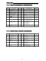
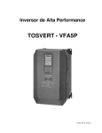
1. Interface Board Diagram
Standoff mounting holes
Plated SHIELD connection
point for grounding (refer to
Section 3).
Standoff mounting holes
5
Network connector (CN1)
2. Interface Board Installation / Removal
The Profibus Communications Option ROM enclosed with the Profibus kit is
compatible only with G3 inverters with V120 or later main software. An error will
occur if the option ROM is installed in an inverter with pre-V120 main software. The
main software version number is printed on the CPU package (IC1) on the control
board. Additionally, this version number can be read from inverter memory by
displaying the parameter CPU VERSION in GROUP:UTILITY PARAMETERS. If you
are unsure of the software version of your inverter, please contact Toshiba
International Corporation for more information.
The Profibus option ROM version number is printed on the label attached to the
ROM. The option ROM version number can also be read from the inverter’s memory
and displayed on the LCD panel after initialization by displaying the parameter ROM
VERSION in GROUP:UTILITY PARAMETERS. The option ROM version number
replaces the standard ROM version number after installation/initialization.
IMPORTANT NOTE: The option ROM included with the Profibus interface kit
is for installation into G3 230V/460V units only. Do not install the option ROM into
any other inverter unit (such as H3, E3, or G3 600V units). All inverter units other
than the G3 230V/460V series are shipped from the factory with full communications
capability, and installation of the option ROM may cause incorrect operation or
inverter damage.
Please note that due to internal mechanical clearances, not all Profibus connectors
can be used on all inverter units. Ensure that the Profibus connector that you plan on
using does not come into contact with any of the drive’s internal components, circuit
boards or brackets. Toshiba has determined that connectors such as the ERNI
103648 (non-terminated) and 103649 (terminated) will work for all installations. If you
have difficulty locating a connector which will work properly in your unit, please
contact Toshiba International Corporation for assistance.
Additionally, certain drive models require a modified panel support bracket to allow
installation of the Profibus interface. Specifically, all G3 460v 10HP through 50HP
and 230v 7.5HP through 25HP units require a modified panel support bracket. To
obtain this support bracket, contact your local distributor or Toshiba International
Corporation.
2.1 Before Installation
All parameters will be automatically reset to the factory default values after the option
ROM is installed in the inverter. If it is desired to retain the current parameter
settings, the user should access the user-changed parameter group to display and
record all the parameters and setting values that have been changed from factory
defaults. Even if the current settings are saved to non-volatile memory by setting the
STANDARD SETTING MODE SELECTION parameter in GROUP:UTILITY
*
PARAMETERS to 5 , they will be erased from memory during initialization of the option
ROM.
6
•=
Setting the standard mode selection parameter will be referred to in this manual
as performing a TYPE X RESET, where X is the parameter setting value.
2.2 Installation Procedure
Installation of the TOSHIBA Profibus option ROM and interface board into a
TOSVERT-130 G3 inverter should only be performed by a qualified technician
familiar with the maintenance and operation of the G3. To install the option ROM and
interface board, complete the following steps:
1. Record the option ROM version number located on the label of the option ROM in
the following box. The option ROM version is the number immediately following
the “V” on the ROM label. For example, if the label indicates “V6402”, the option
ROM version is 6402. This version number will be used later in the installation
.
process. Option ROM version =
Record the standard ROM version number prior to option ROM installation. The
standard ROM version can be read from parameter ROM VERSION in
GROUP:UTILITY PARAMETERS.
Standard ROM version =
.
CAUTION!
2.
Verify that all input power sources to the inverter have
been turned OFF and are locked and tagged out.
3.
Wait at least 5 minutes for the inverter’s electrolytic
capacitors to discharge before proceeding to step 4. Do not touch any internal
parts with power applied to the inverter, or for at least 5 minutes after
power to the inverter has been removed. A hazard exists temporarily for
electrical shock even if the source power has been removed.
4.
Remove the inverter’s cover (open the door on units with hinged doors).
Verify that the CHARGE LED has gone out before continuing the installation
process.
DANGER!
5. Loosen the 4 screws attaching the G3’s operation panel support bracket to the
control board support bracket, and then remove the operation panel and support
bracket as a unit (refer to Figure 1).
7
operation panel
support bracket
operation panel support
bracket screws
Figure 1: G3 with front cover removed
6.
CAUTION!
The option ROM PCB assembly and interface board are
static-sensitive devices. Standard electrostatic-sensitive component handling
precautions should be observed. Locate the option ROM connector, labeled
CN41, on the lower-left side of the control PCB. Line up the connector on the
back of the option ROM PCB with CN41. Install the option ROM by pressing
gently but firmly on the option ROM PCB until a slight “click” is felt. Verify that the
option ROM PCB is seated properly and firmly in CN41. If the option ROM
connector does not appear to be mating with CN41 properly, verify that the ROM
is oriented properly and that there are no obstructions in either connector.
7. Install the 4 nylon standoffs into the holes provided in the control board support
bracket (refer to Figure 2).
8
standoff mounting holes
Figure 2: G3 with front cover and operation panel support bracket
removed
8. Install the Profibus network cable through the access holes at the bottom of the
inverter and route the cable in order to make connections to the interface board
connector (CN1). Take care to not route the cable near any sharp edges or in
positions where it may be pinched.
9. Connect the Profibus cable to the interface board connector (CN1). If a ground
cable is going to be used, attach the ground cable to the plated hole near CN1 on
the lower-right portion of the Profibus board (refer to section 3).
CAUTION!
Extremely high voltages exist in the area near the Profibus
interface board and connector. Ensure that no stray wires come into contact with
any internal inverter components. Also ensure that the communications cable is
not routed in such a manner that it may come into contact with high-voltage
inverter components, or inverter components that may heat up during operation
and damage the cable insulation.
10. Install the interface board into the inverter by carefully aligning the 4 nylon
standoffs with the 4 mounting holes provided in the interface board. Ensure that
connector CN5A on the back side of the interface board is aligned with connector
CN5 on the front side of the control board.
11. Press the interface board firmly onto the standoffs and connector CN5 until the
standoff retaining tabs lock. Ensure that CN5 and CN5A are thoroughly
interlocked.
12. Carefully re-install the operation panel and support bracket and tighten the 4
screws that attach the operation panel support bracket to the control board
support bracket. Once installed, take a moment to verify that all interface board
and network components have sufficient clearance from other drive components.
9
13. If a ground cable is being used, connect the ground cable to the selected ground
point.
14. Reinstall the inverter’s cover (close and latch the door on units with hinged
doors).
DANGER!
Do not operate the unit with the cover off / cabinet
door open.
15. Turn all power sources to the inverter unit ON, and verify that the inverter
functions properly. If the inverter unit does not appear to power up, or does not
function properly, immediately turn power OFF. Repeat steps 2 ∼ 4 to remove
all power from the inverter. Then, verify all connections. Contact Toshiba
International Corporation for assistance if the problem persists.
16. To perform final verification that the option ROM is installed properly, display the
value of the ROM VERSION parameter in GROUP:UTILITY PARAMETERS. This
number should match the option ROM version number that was recorded in step
1. If this parameter value does not match the option ROM version number
recorded in step 1, repeat steps 2 ∼ 4 to remove all power from the inverter,
then re-verify that the option ROM is installed properly. If the option ROM
appears to be installed properly, but the version numbers still do not match,
contact Toshiba International Corporation for further assistance.
10
2.3 Removal
Removal of the Profibus interface board from a TOSVERT-130 G3 inverter should
only be performed by a qualified technician familiar with the maintenance and
operation of the G3. In order to protect the interface board connector’s reliability, do
not repeatedly connect and disconnect the interface. Use the following procedure if it
becomes necessary to remove the Profibus interface board from the inverter.
CAUTION!
Do not remove the interface board while power is applied to
the inverter. Removing the interface board with power applied may damage the
inverter.
2.3.1 Before Removal
The inverter will display an error message if the option ROM becomes dislodged or is
removed from its socket. The inverter must be reset to clear this error. Therefore, all
parameters will be automatically reset to the factory default values after an option
ROM has been removed from the inverter. If it is desired to retain the current
parameter settings, the user should access the user-changed parameter group to
display and record all the parameters and setting values that have been changed
from factory defaults. Even if the current settings are saved using the TYPE 5
RESET function, they will be erased from memory during the re-initialization of the
inverter after the option ROM has been removed.
2.3.2 Removal Procedure
1.
CAUTION!
Verify that all input power sources to the inverter have
been turned OFF and are locked and tagged out.
DANGER!
2.
Wait at least 5 minutes for the inverter’s electrolytic
capacitors to discharge before proceeding to step 3. Do not touch any internal
parts with power applied to the inverter, or for at least 5 minutes after
power to the inverter has been removed. A hazard exists temporarily for
electrical shock even if the source power has been removed.
3.
Remove the inverter’s cover (open the door on units with hinged doors).
Verify that the CHARGE LED has gone out before continuing the removal
process.
4. Loosen the 4 screws attaching the operation panel support bracket to the control
board support bracket and remove the operation panel and support bracket as a
unit (refer to Figure 3).
11
operation panel
support bracket
operation panel support
bracket screws
Figure 3: G3 with front cover removed
5.
CAUTION!
The option ROM PCB and Profibus interface board are
static-sensitive devices. Standard electrostatic-sensitive component handling
precautions should be observed. Release the 4 corners of the interface board
from the standoffs by pressing down on the standoff locking tabs with a small flatheaded screwdriver. Be careful to not apply any abnormal stress to the interface
board while performing this, as this may damage the interface board or control
board connectors.
6. Remove the interface board from the inverter.
7. Disconnect the communications cable from the interface board connector (CN1),
and pull the cable out through the access holes at the bottom of the inverter.
8. Locate the option ROM in the option ROM connector, labeled CN41, on the
lower-left side of the control PCB. Gently work the option ROM PCB up and
down while pulling on it until the ROM releases from the control PCB option ROM
connector.
IMPORTANT NOTE: Do not remove the option ROM on inverter units that
were received from the factory with option ROMs pre-installed. Units that are
shipped from the factory with option ROMs pre-installed (H3 and 600V G3 units,
for example) require these ROMs for correct operation, and removal of the option
ROM may cause incorrect operation or inverter damage. If you are in doubt
about the requirement of an option ROM in your inverter unit, contact Toshiba
International Corporation for assistance.
9. Carefully re-install the operation panel and support bracket and tighten the 4
screws that attach the operation panel support bracket to the control board
support bracket.
12
10. Reinstall the inverter’s cover (close and latch the door on units with hinged
doors).
DANGER!
Do not operate unit with the cover off / cabinet
door open.
11. Turn all power sources to the inverter unit ON, and verify that the inverter
functions properly. If the inverter unit does not appear to power up, or does not
function properly, immediately turn power OFF. Repeat steps 1 ∼ 3 to remove
all power from the inverter. Then, verify all connections. Contact Toshiba
International Corporation for assistance if the problem persists.
12. To re-initialize the inverter after the ROM has been removed, perform a TYPE 3
reset. After the initialization sequence, display the value of the ROM VERSION
parameter in GROUP:UTILITY PARAMETERS. This number should match the
standard ROM version number that was recorded prior to option ROM installation.
If this parameter value does not match the value recorded earlier, contact
Toshiba International Corporation for further assistance.
13
3. Grounding
Grounding is of particular importance for reliable, stable operation. Communication
system characteristics may vary from system to system, depending on the system
environment and grounding method used. The Profibus interface card is provided
with a plated SHIELD connection point by CN1, on the lower right-hand side of the
board. This SHIELD connection point is directly connected to the metallic housing of
the DB9 connector, which should then be connected to the shield of the Profibus
network cable through the Profibus connector. To ground the network cable shield,
therefore, connect a wire with lug terminal to this SHIELD point, and then connect the
other end of the wire to an appropriate ground. For specific details and requirements
regarding protective grounding and the Profibus network, refer to the Profibus
Standard (DIN 19245, part 1).
Please be sure to consider the following points for making proper ground
connections:
Grounding method checkpoints
1. Make all ground connections such that no ground current flows through the
inverter case.
2. Ensure that all grounds are connected to points that are at the same potential as
inverter grounds.
3. Do not connect the Profibus interface board's SHIELD connection point to a
power ground or any other potential noise-producing ground connection (such as
the inverter's E/GND terminal).
4. Do not make connections to unstable grounds (paint-coated screw heads,
grounds that are subjected to inductive noise, etc.)
4. Equipment Specifications
Item
Operating Environment
Operating Temperature
Storage Temperature
Relative Humidity
Vibration
Grounding
Cooling Method
Specification
Indoors, less than 1000m above sea level, do not
expose to direct sunlight or corrosive / explosive gasses.
-10 ∼ +40°C (+14 ∼ +104°F)
-25°C ∼ +65°C (-13 ∼ +149°F)
20% ∼ 90% (without condensation)
5.9m/s2 {0.6G} or less (10 ∼ 55Hz)
According to DIN 19245, part 1
Self-cooled
14
5. Maintenance And Inspection
Preventive maintenance and inspection is required to maintain the Profibus
communication interface in its optimal condition, and to ensure a long operational
lifetime. Depending on usage and operating conditions, perform a periodic
inspection once every three to six months. Before starting inspections, always turn
off all power supplies to the inverter unit, and wait at least five minutes after the
inverter’s “CHARGE” lamp has gone out.
DANGER!
Do not touch any internal parts with power applied
to the inverter, or for at least 5 minutes after power to the inverter has been
removed. A hazard exists temporarily for electrical shock even if the source
power has been removed.
Inspection Points
•= Check that the network connector screws are not loose. Tighten if necessary.
•= Check that there are no defects in any attached grounding wire terminal crimp
points. Visually check that the crimp points are not scarred by overheating.
•= Visually check the wiring and cables for damage.
•= Clean off any accumulated dust and dirt. Place special emphasis on cleaning the
ventilation ports of the inverter and all installed PCBs. Always keep these areas
clean, as adherence of dust and dirt can cause premature component failure.
•= If use of the inverter unit is discontinued for extended periods of time, turn the
power on at least once every two years and confirm that the unit still functions
properly.
•= Do not perform hi-pot tests on the inverter or Profibus interface board, as they
may damage the unit’s internal components.
Please pay close attention to all periodic inspection points and maintain a good
operating environment.
15
6. Storage And Warranty
6.1 Storage
Observe the following points when the Profibus interface board is not used
immediately after purchase or when it is not used for an extended period of time.
•= Avoid storing the interface board in places that are hot or humid, or that contain
large quantities of dust or metallic dust. Store the interface board in a wellventilated location.
•= When not using the Profibus interface board for an extended period of time, turn
the power on at least once every two years and confirm that it still functions
properly.
6.2 Warranty
The Profibus communications interface kit is covered under warranty for a period of
12 months from the date of installation, but not to exceed 18 months from the date of
shipment from the factory. For further warranty or service information, please contact
Toshiba International Corporation.
16
7. G3 Parameter Settings
Profibus interface board communications are enabled by setting parameter
COMMUNICATION SELECTION in GROUP:COMMUNICATION SETTING PARAMETERS
to 2 (Profibus, Modbus, DeviceNet). None of the Tosline-F10 communication
parameter settings apply when using the Profibus interface. For more information on
methods for changing parameter settings, refer to the TOSHIBA G3 Operation
Manual.
The following is a list of the parameter settings that are required during setup to
enable Profibus communications:
Parameter
BLIND FUNCTION
SELECTION
COMMUNICATIONS PARMS
BLIND
COMMUNICATION
SELECTION
INVERTER ID NUMBER
Note:
Group
GROUP:UTILITY
PARAMETERS
GROUP:UTILITY
PARAMETERS
GROUP:COMMUNICATION
SETTING PARAMETERS
GROUP:COMMUNICATION
SETTING PARAMETERS
Required Value
1
1
2
any value other than
126 ∼ 255.
Although the INVERTER ID NUMBER parameter can be set from 0 to 255,
the allowable Profibus slave addresses range only from 0 to 125. Therefore,
if this parameter is set to a value from 126 to 255, the Profibus interface card
will trip “OPTION PCB ERROR” upon initialization. To correct this error, set
the INVERTER ID NUMBER parameter to a value from 0 to 125.
To implement any parameter changes in GROUP:COMMUNICATION SETTING
PARAMETERS, the drive must be reset after making the changes.
If the drive into which a Profibus communications interface board is installed trips
“OPTION PCB ERROR” for any reason during initialization or operation (for example,
if it becomes loose from its mounting connections), it is incapable of being reset via
the Profibus network. When this trip condition occurs, therefore, the drive can only
be reset locally via the panel or control terminal block.
If drive control (frequency command input, RUN/STOP, etc.) is to be performed via
the Profibus network, the following inverter parameters must also be set as shown:
Parameter
Group
COMMAND MODE SELECTION
FREQUENCY MODE SELECTION
GROUP:UTILITY PARAMETERS
GROUP:UTILITY PARAMETERS
Required
Value
3
3
Of course, input data can always be monitored from the network regardless of the
settings of COMMAND MODE SELECTION and FREQUENCY MODE SELECTION. Also
note that if the COMMAND MODE SELECTION or FREQUENCY MODE SELECTION
parameters are changed while the drive is running, the change will not take effect
until the next time the drive is stopped.
17
8. Feature Summary
The Toshiba Profibus-DP interface provides a wide array of network data access and
drive control features. Combined with the flexible configuration and high-speed data
transfer capabilities of the Profibus network, this allows powerful networked control
and monitoring systems to be designed. Some of the main features provided in the
G3 Profibus-DP interface which allow for this control and configurability are briefly
described here:
Protocol
Profibus DP (Decentralized Periphery). The interface can also co-exist
simultaneously on networks using Profibus-FMS.
Network Baud Rates
Supports all Profibus baud rates from 9.6kbaud to 12Mbaud. The network baud rate
is automatically detected and continuously monitored during operation; no parameter
settings are necessary.
Global Control Functions
•= Freeze mode: Input (monitor) data values are held constant at the drive until the
next “freeze” command or an “unfreeze” command is received.
Used primarily for synchronized monitoring of multiple Profibus
nodes.
•= Sync mode:
Output (control) data values are held constant at the drive until the
next “sync” command or an “unsync” command is received. Used
primarily for synchronized control of multiple Profibus nodes.
•= Clear_Data:
All output (control) data values are cleared to “0”.
Address Change Functions
Set_slave_address function supported – allows modification of the drive’s INVERTER
ID NUMBER parameter. The INVERTER ID NUMBER parameter can also be
changed while in the DATA_EXCHANGE state by accessing parameter register 204
(hex). Refer to sections 10 and 11 of this document for more information on
accessing parameter registers.
Network Watchdog
A network watchdog function is always operating within the interface – in the event of
a disconnection from the network or loss of the network master, the interface will
automatically stop the drive for safety (note that either the COMMAND MODE
SELECTION or FREQUENCY MODE SELECTION parameter must be set to 3 (network
control) in order for the drive to stop when a watchdog time-out occurs).
18
Indicators
1 green LED is provided to indicate when the interface has achieved the
DATA_EXCHANGE state with the network master. This serves as a convenient
indicator that the master and drive are configured properly and are exchanging data.
Isolation
The network interface portion of the Profibus-DP board is fully optically-isolated for
optimal noise-immunity characteristics.
Network Connector
The network interface is a standard DB9 connector with the following signals
provided:
Pin Number
3
4
5
6
8
1, 2, 7, 9
Function
Profibus network “B” (positive) data line
RTS signal – direction control for fiber optic network
interface
DGND – power supply ground internally connected to the
interface board’s isolated ground
VP – power supply +5v internally connected to the
interface board’s isolated P5.
Profibus network “A” (negative) data line
No connection
In/Out
In/out
Out
In/out
-
In addition to the above signals, the metallic housing of the DB9 connector is
connected to the shield section of the interface board. The shield section contains a
plated connection point where a ground wire can be attached to connect the network
cable shield to ground. Refer to section 3 of this document for more information
related to grounding.
Input/Output Data
The interface’s cyclic data sizes are fixed at 8 bytes of output (control) data
configured as 4 words, and 16 bytes of input (status) data configured as 7 words and
2 bytes. For detailed explanations of the format and usage of this data, refer to
sections 9 and 10 of this document.
19
9. Exchanged Data Structures
9.1 Output (Control) Data Format
The output data structure from the network master to the G3 Profibus interface card
is comprised of 8 bytes structured as 4 words:
Offset
Data
0
Command word
high byte
1
Command word
low byte
2
Frequency
command high byte
3
Frequency
command low byte
4
Parameter number
/ action high byte
5
Parameter number
low byte
6
Parameter data to
write high byte
7
Parameter data to
write low byte
Explanation
Bit-level drive control command word (refer to
Table 1 : Command Word Format)
Drive’s frequency command
Parameter action bits and upper 4 bits of the
parameter register number. Refer to section 10
for a detailed explanation of this data word
During parameter register writes, this word
contains the data to write. Refer to section 10
for a detailed explanation of this data word
The data contained in the frequency command word must be the desired frequency
command multiplied by 100, and then converted to hexadecimal. In other words, if a
frequency command of 55.34Hz is desired, then 55.34 x 100 = 5534, which
converted to hexadecimal is 0x159E. The frequency command high byte (offset 2)
must therefore contain 0x15, and the frequency command low byte (offset 3) must
contain 0x9E.
In this way, the G3’s allowable frequency command range of 0.00Hz ∼ 400.00Hz
equates to network values of 0x0000 ∼ 0x9C40.
Regardless of the frequency command value sent via the Profibus network to the
drive, the actual operating frequency of the drive will still be limited locally by the
LOWER LIMIT FREQUENCY, UPPER LIMIT FREQUENCY, and MAXIMUM OUTPUT
FREQUENCY parameter settings.
20
Table 1 : Command Word Format
High Byte
Low Byte
Bit
Function
0
RUN command
1
STOP Command (has priority
over RUN command)
2
Forward / reverse run
selection
3
Acc/dec #1 / #2 selection
4
5
6
7
Reserved
Reserved
Reserved
Jog mode selection
8
Feedback control
9
Compulsory DC injection
braking mode
A
Fundamental parameter
switching
B
Gate block (coast stop)
command
C
Emergency off command
D
Reset command (trip clear)
E
F
Reserved
Reserved
Setting
0: Stop
1: Run
0: run enabled
1: stop
0: reverse
1: forward
0: Acc / dec #1
1: Acc / dec #2
Value is ignored
0: Normal (acc/dec mode)
1: Jog mode
0: Feedback valid
1: Feedback invalid
0: No compulsory DC injection braking
1: Compulsory DC injection below DC
INJECTION START FREQUENCY
0: V/F #1
1: V/F #2
0: Normal
1: Gate block
0: Does nothing
1: Emergency off
0: Does nothing
1: Reset when tripped
Value is ignored
21
9.2 Input (Status) Data Format
The input data structure from the G3 Profibus interface card to the network master is
comprised of 16 bytes structured as 7 words and 2 independent bytes:
Offset
Data
0
Status word
high byte
Explanation
Bit-level drive status word (refer to Table 2 :
Status Word Format)
1
Status word
low byte
2
Output frequency
high byte
3
Output frequency
low byte
4
IV input terminal
value high byte
5
IV input terminal
value low byte
6
RR input terminal
value high byte
7
RR input terminal
value low byte
8
Input terminal
monitor high byte
9
Input terminal
monitor low byte
10
Drive output
current monitor
0x00 ∼ 0xFF corresponds to 0 ∼ 255% drive
rated load current
11
Drive output
voltage monitor
0x00 ∼ 0xFF corresponds to 0 ∼ 255% drive
rated output voltage
12
Parameter number
/ action high byte
13
Parameter number
low byte
14
Parameter data
response high byte
15
Parameter data
response low byte
Drive’s current operating frequency
Continuously reports the value of the drive’s IV
analog input terminal. 0 ∼ 100% terminal input
corresponds to data values of 0x0000 ∼ 0xFFFF
Continuously reports the value of the drive’s RR
analog input terminal. 0 ∼ 100% terminal input
corresponds to data values of 0x0000 ∼ 0xFFFF
Bit-level status word of drive’s digital input
terminals (refer to Table 3 : Input Terminal
Monitor Word Format)
Parameter action bits and upper 4 bits of the
parameter register number. Refer to section 10
for a detailed explanation of this data word
During parameter register reads, this word
contains the requested data response. Refer to
section 10 for a detailed explanation of this data
word
22
In order to determine the drive’s actual output frequency, the data contained in the
output frequency word (offsets 2 and 3) must first be converted from hexadecimal to
decimal, and then divided by 100. For example, if the output frequency high byte is
0x12 and the output frequency low byte is 0x34, then 0x1234 converted to decimal is
4660. Dividing this number by 100, the actual operating frequency of 46.60Hz is
obtained.
In this way, network data values of 0x0000 ∼ 0x9C40 correspond to the G3’s actual
allowable output frequency range of 0.00Hz ∼ 400.00Hz.
Table 2 : Status Word Format
High Byte
Low Byte
Bit
Function
0
Run / stop status
1
Run enable status
2
Forward / reverse status
3
Accel / decel #1 / #2 selection
status
4
5
Reserved
Fault status
6
7
Reserved
Jog mode status
8
Feedback enable status
9
Compulsory DC injection
braking mode
A
Fundamental parameter
switching
B
Coast stop command status
C
Emergency off command
D
E
Reserved
Main Circuit Undervoltage
F
Reserved
Value
0: Stopped
1: Running
0: Run enabled
1: Stopped
0: Reverse
1: Forward
0: Accel / decel #1
1: Accel / decel #2
Always “0”
0: Faulted
1: Not Faulted
Always “0”
0: Normal (accel/decel mode)
1: Jog mode
0: Feedback invalid
1: Feedback valid
0: DC injection braking inactive
1: DC injection braking active
0: V/F #1
1: V/F #2
0: Normal
1: Coast to stop
0: Normal
1: Emergency off
Always “0”
0: Normal
1: Undervoltage
Always “0”
23
High Byte
Low Byte
Table 3 : Input Terminal Monitor Word Format
Bit
Terminal
0
F
1
R
2
S1
3
S2
4
S3
5
S4
6
S5 (option)
7
S6 (option)
8
9
A
B
C
D
Reserved
Reserved
Reserved
Reserved
Reserved
S7 (option)
E
RES
F
ST
Value
0: Terminal – CC open
1: Terminal – CC shorted
0: Terminal – CC open
1: Terminal – CC shorted
0: Terminal – CC open
1: Terminal – CC shorted
0: Terminal – CC open
1: Terminal – CC shorted
0: Terminal – CC open
1: Terminal – CC shorted
0: Terminal – CC open
1: Terminal – CC shorted
0: Terminal – CC open
1: Terminal – CC shorted
0: Terminal – CC open
1: Terminal – CC shorted
Always 0
0: Terminal – CC open
1: Terminal – CC shorted
0: Terminal – CC open
1: Terminal – CC shorted
0: Terminal – CC open
1: Terminal – CC shorted
9.3 Diagnostics
When the drive trips, 1 byte of high-priority user diagnostics is supplied to the master.
The value of the diagnostics byte is the drive’s fault code. Refer to section 11.3 for a
list of drive fault codes.
24
10. Parameter Register Access
10.1 Parameter Number / Action Output Words
To access inverter parameters, 2 output words are provided in the output data
structure. The structure of these 2 output words is as follows:
15
14
13
12
Reserved
Req1
Req0
Bit #:
Reserved
Parameter number / action word
11
8
7
4
3
0
Parameter number (12 bits)
Parameter number / action
high byte (offset 4)
Parameter number
low byte (offset 5)
Parameter data write word
Bit #:
15
12
11
8
7
4
3
Parameter data (16 bits)
Parameter data to write
high byte (offset 6)
Parameter data to write
low byte (offset 7)
25
0
10.2 Parameter Number / Action Input Words
The response by the G3 interface card to parameter read and write requests is
placed in 2 input words of the input data structure. The structure of these 2 input
words is as follows:
15
14
13
12
0
0
Resp0
Bit #:
Resp1
Parameter number / action response word
11
8
7
4
3
0
Parameter number (12 bits)
Parameter number / action
response high byte (offset 12)
Parameter number
response low byte (offset 13)
Parameter data / error code response word
Bit #:
15
12
11
8
7
4
3
Parameter data / error code (16 bits)
Parameter data response
high byte (offset 14)
Parameter data response
low byte (offset 15)
26
0
10.3 Parameter Access Procedure
In order to read from a parameter or write to a parameter, 2 control bits are provided.
These bits, labeled Req1 and Req0 in the Parameter number / action word, can have
the following values:
Req1
0
0
1
1
Req0
Meaning
0........... No action (idle state)
1........... Parameter read
0........... Parameter write
1........... Reserved: do not use
Similarly, when the drive responds to a parameter read or write request, 2 status bits
are provided. These bits, labeled Resp1 and Resp0 in the Parameter number /
action response word, can have the following values:
Resp1
0
0
1
1
Resp0
Meaning
0........... No action (idle state acknowledge)
1........... Parameter read success acknowledge
0........... Parameter write success acknowledge
1........... Error indication
Performing a parameter read or write action from the Profibus master involves the
following process:
1. Send a “no action” code (Req1=0 and Req0=0). Every parameter access must
begin from the idle state. Once this state is sent, the Profibus master must then
wait for the G3 Profibus interface card to respond with an idle state acknowledge
(Resp1=0 and Resp0=0).
2. If the action is to be a data write, set the parameter data in the parameter data
write word. If the action is to be a data read, the parameter data write word value
is irrelevant.
3. Set the parameter register number (12 bits) and action code (Req1 and Req0).
For a list of parameter register numbers, refer to section 11.
4. Once the G3 Profibus interface receives the read or write request, it will begin
processing it. Typically, the drive will require from 20ms to 40ms to complete
each parameter access request (read or write).
5. Once the drive has completed the request, it will place its response in the
parameter number / action response word and data / error code response word:
•= If the request was a read, and the read was performed successfully, this will
be indicated to the master by Resp1:Resp0 changing from 0:0 to 0:1. The
parameter number response (12 bits) will equal the accessed parameter
number, and the resulting data read will be placed in the data / error code
response word.
•= If the request was a write, and the write was performed successfully, this will
be indicated to the master by Resp1:Resp0 changing from 0:0 to 1:0. The
parameter number response (12 bits) will equal the accessed parameter
number, and the data written to the drive will be reflected in the data / error
code response word.
27
•= If an error occurred during the read or write request, this will be indicated to
the master by Resp1:Resp0 changing from 0:0 to 1:1. The parameter
number response (12 bits) will equal the parameter number that the master
was attempting to access, and an error code reflecting the failure cause will
be placed in the data / error code response word. For a list of possible error
codes, refer to section 10.4.
6. In order to perform another parameter read or write, the master must once again
send a “no action” code (Req1=0 and Req0=0), and the drive must once again
respond with an idle state acknowledge (Resp1=0 and Resp0=0) before the next
read or write action can take place. Until a “no action” code is sent to the drive,
the drive will ignore all data in the Parameter number / action word and
Parameter write data word. Also, as long as the master sends the “no action”
code, the drive will loop-back in the parameter number / action response word
and parameter data / error code response word whatever data is sent to it in the
corresponding output words.
10.4 Register Access Error Codes
When a parameter read or write error occurs, one of the following error codes will be
returned in the Parameter data response word (offsets 14 and 15 of the input data
structure):
Error Code
Meaning
0x0001 ................ cannot execute
0x0002 ................ data error (written data value outside of valid range)
0x0003 ................ invalid register
0x0004 ................ attempt to write to a read-only register
0x0005 ................ attempt to read from a write-only register
0x0006 ................ other / unclassified error
28
11. Parameter Registers
How To Use This Section:
This section contains tables which describe all of the parameter registers accessible
from the Profibus network. The descriptions for the columns in the listed tables are
as follows:
Register ............The register number used to access the parameter.
Bit .....................This column only applies to read-only registers (section 11.1). If the
register is comprised of a collection of individual bit-oriented status
items (for example, register 0D), this column will indicate which bit(s)
in the word-sized register the corresponding parameter described in
the Function column uses (bit 0 = LSB, bit F = MSB). If the
parameter uses the whole register, "word" will appear in this column,
indicating the parameter consumes the entire register (this does not
mean, however, that all register bits are used: refer to the
explanation for Mask below). All read/write registers (section 11.2)
have word-size data. Other possible values in this column are "low
byte" (bits 0 ∼ 7) and "high byte" (bits 8 ∼ F).
Function............Describes the function accessed through this parameter register.
Bank .................0 = RAM (volatile), 1 = EEPROM (nonvolatile), 0/1 = RAM &
EEPROM, 2, 3 and 6 = code space (read-only). IMPORTANT: the
inverter’s EEPROM has a life span of 10,000 write cycles. Do not
write to a read/write holding register whose bank is listed as 1 or 0/1
more than 10,000 times.
Mask .................The data bits within a register that are not covered by the
hexadecimal mask (for example, bits 8 ∼ F if the mask is 00FF) will
always be returned as 0 during data reads and will be ignored during
data writes. For example, if a hexadecimal value of AB98 is sent to
a register whose mask is 00FF, the actual value written to the
register's corresponding parameter will be 0098. As this is not
considered an error, no exception response will be generated if this
type of extraneous data condition occurs.
Adjustment Range ... Indicates valid data settings in real terms (Hz, ON/OFF, etc.)
Multiplier ...........Indicates scaling factor used to convert Adjustment Range data into
integer values. The equation used for this conversion is:
Actual Holding Register Data = Real Data ÷ Multiplier
For example, if 60.00Hz MAXIMUM OUTPUT FREQUENCY were
desired, register 26 must be set to [60.00 ÷ 0.01] = 6000 decimal (=
1770 hex).
29
Example Table Excerpt:
Register
26
27
Function / Title
MAXIMUM OUTPUT
FREQUENCY
BASE FREQUENCY #1
28
BASE FREQUENCY
VOLTAGE SELECT
29
MAXIMUM
VOLTAGE
REVERSE
DISABLE
2A
OUTPUT
#1
OPERATION
SELECT
(∗
∗)
(∗
∗)
Bank
Mask
Adjustment Range
0/1
FFFF
0BB8 ∼ 9C40 (30.00∼400.00)
0/1
FFFF
0/1
0030
09C4 ∼ 9C40 (25.00∼400.00)
0000: Input voltage level
0020: Automatic setting
0030: Stationary setting
0/1
FFFF
0000 ∼ 0258 (0 ∼ 600)
0/1
0020
0000: Reverse allowed
0020: Reverse not allowed
Multiplier
0.01
0.01
(0)
(1)
(2)
1
(0)
(1)
Other Programming Register Notes:
•= All register numbers indicated are in hexadecimal notation (for example, 29 hex =
41 decimal). Occasionally, hexadecimal notation in this document may also take
the form of a number beginning with “0x”.
•= Throughout this document, the abbreviations "LL", "UL", and "Fmax" will stand for
LOWER LIMIT FREQUENCY, UPPER LIMIT FREQUENCY, and MAXIMUM
OUTPUT FREQUENCY, respectively.
•= Reading from or writing to registers marked as "Reserved" will generate an
“invalid register” error (error code 0x0003)
•= Certain parameter registers cannot be written to while the inverter is running.
These registers will be indicated by the character (∗). If an attempt is made to
write to these registers while the inverter is running, a “cannot execute” error
(error code 0x0001) will be generated.
•= The parameter register data for all read/write registers with Bank information
listed as 0/1 will be retrieved from bank 0 (RAM) during reads and will be written
to both banks 0 and 1 (RAM and EEPROM) during writes.
•= All parameters in GROUP:COMMUNICATION SETTING PARAMETERS (section
11.2.10) are retrieved by the drive from non-volatile memory upon inverter
initialization only. When any of these registers are modified, therefore, the drive
must be reset for the changed values to take effect.
•= If the COMMAND MODE SELECTION or FREQUENCY MODE SELECTION
parameters are changed while the drive is running, the change will not take effect
until the next time the drive is stopped.
30
11.1 ReadRead-Only Registers
Register
Bit
01 ∼ 09
0A
word
Reserved
Function
word
0B
word
RX terminal analog input
value
Frequency command
monitor
0C
word
0D
word
Input voltage monitor(Note 1)
Output terminal status
monitor
Bank
Mask
0
FFFF
Adjustment Range
0000 ~ 7FFF (-100% ~ 0%)
7FFF ~ FFFF (0% ~ 100%)
Multiplier
0
FFFF
0
FFFF
0000 ∼ 9C40
(0.00 ∼ 400.00 Hz)
0 ~ 255%
0
00FF
Refer to Table 4 (page 32)
1
0.01
0.1
0E
word
Inverter Status 1
0
FFFF
Refer to Table 5 (page 32)
0F
word
Inverter Status 2
0
00FF
Refer to Table 6 (page 32)
10
word
Present trip
0
00FF
11
4th Past trip (most recent)
0
7F00
13
high
byte
low
byte
high
byte
low
byte
word
14
12
3rd past trip
2nd past trip
007F
0
1st past trip (oldest)
Refer to section 11.3 for fault
codes
7F00
007F
Pre-compensation output
frequency
0
FFFF
0000 ∼ 9C40
(0.00 ∼ 400.00 Hz)
0.01
word
Post-compensation output
frequency
0
FFFF
0000 ∼ 9C40
(0.00 ∼ 400.00 Hz)
0.01
15
16
word
word
Torque current monitor
Excitation current monitor
0
0
FFFF
00FF
(Note 2)
00 ∼ FF (0 ~ 255%)
0.01
1
17
word
PID feedback value
0
FFFF
(Note 2)
0.02
18
19
1A
1B
1C
word
word
word
word
word
Motor overload ratio
Inverter overload ratio
DBR overload ratio
Input power (%)
Input power (kW)
0
0
0
0
0
FFFF
FFFF
FFFF
FFFF
FFFF
1D
word
Output power (%)
0
FFFF
(Note 2)
1E
word
Output power (kW)
0
FFFF
(Note 2, Note 3)
1F, 20
word
Reserved
21
word
Input / output power units
0
0008
22
word
Command mode status
0
0003
23
word
Frequency mode selection
status
0
000C
0000: 0.01kW
0008: 0.1kW
0000: terminal
0001: panel
0002: option
0003: RS232C
0000: terminal
0004: panel
0008: option
000C: RS232C
24
low
byte
high
byte
word
Profibus interface card
software revision
Profibus interface card
software version
Output current (amps)
FFFF
0.0 ~ 6553.5 A
0.1
25
0 ~ 65535
0 ~ 65535
0 ~ 65535
0 ~ 6553.5
100/65535
100/65535
100/65535
0.1
(Note 3)
0.1
(Note 1)
These monitor voltage units are not affected by the setting of VOLTAGE UNITS SELECTION in
GROUP:UTILITY PARAMETERS; they are always in units of %.
(Note 2)
These registers use signed data (data values larger than 7FFFH are negative). If the register data is
8000H or larger, the actual value can be obtained by: actual value = - [FFFFH - (register data) + 1].
31
(Note 3)
If the input / output power units data is 0, the monitored data is in 0.01kW units, and the multiplier is
0.01. If the input / output power units data is 1, the monitored data is in 0.1kW units, and the multiplier
is 0.1. These values are automatically set according to the inverter’s capacity.
Table 4: Output Terminal Status Monitor (register 0D)
Lower
Byte
Bit
Output Terminal
0
1
Single-Bit
Read Mask
bit 0
unused (always 0)
bit 1
unused (always 0)
bit 2
bit 3
bit 4
bit 5
bit 6
bit 7
FAN
FL
MS relay
OUT (option)
RCH
LOW
OFF
FLB-FLC shorted
OFF
OUTB-OUTC shorted
RCHA-RCHC open
LOWA-LOWC open
ON
FLA-FLC shorted
ON
OUTA-OUTC shorted
RCHA-RCHC shorted
LOWA-LOWC shorted
0004
0008
0010
0020
0040
0080
0
1
Single-Bit
Read Mask
Table 5: Inverter Status 1 (register 0E)
Lower
Byte
Upper
Byte
Bit
Inverter Status
bit 0
running (acc/dec)
running
0001
bit 1
unused (always 0)
bit 2
bit 3
bit 4
forward / reverse
acc/dec #1/#2
for inverter use
reverse
acc/dec #1
forward
acc/dec #2
0004
0008
bit 5
for inverter use
bit 6
for inverter use
bit 7
jog/normal mode
normal (acc/dec)
jog mode
0080
Bit
Inverter Status
0
1
Single-Bit
Read Mask
bit 0
feedback ON/OFF
OFF
feedback active
0001
bit 1
bit 2
bit 3
bit 4
bit 5
DC inj. braking
V/F #1/#2
coasting
emergency off
for inverter use
OFF
V/F #1
not coasting
not in emergency off
DC inj. braking active
V/F #2
coasting
in emergency off
0002
0004
0008
0010
bit 6
for inverter use
bit 7
for inverter use
0
1
Single-Bit
Read Mask
Table 6 : Inverter Status 2 (register 0F)
Upper
Byte
Bit
Inverter Status
bit 0
accelerating
not accelerating
accelerating
0001
bit 1
bit 2
decelerating
for inverter use
not decelerating
decelerating
0002
bit 3
bit 4
retrying
running
0008
0010
bit 5
retry
running (including DC
injection braking)
for inverter use
not retrying
stopped
bit 6
for inverter use
bit 7
tripped
not tripped
tripped
0080
32
11.2 Read/Write Registers
11.2.1 GROUP:FUNDAMENTAL PARAMETERS #1
Register
26
27
Function / Title
MAXIMUM OUTPUT
FREQUENCY
BASE FREQUENCY #1
28
BASE FREQUENCY
VOLTAGE SELECT
29
MAXIMUM
VOLTAGE
REVERSE
DISABLE
2A
(∗
∗)
(∗
∗)
OUTPUT
#1
OPERATION
SELECT
Bank
Mask
Adjustment Range
0/1
FFFF
0BB8 ∼ 9C40 (30.00∼400.00)
0/1
FFFF
0/1
0030
09C4 ∼ 9C40 (25.00∼400.00)
0000: Input voltage level
0020: Automatic setting
0030: Stationary setting
0/1
FFFF
0000 ∼ 0258 (0 ∼ 600)
0/1
0020
0000: Reverse allowed
0020: Reverse not allowed
0000 ~ Fmax
Multiplier
0.01
0.01
(0)
(1)
(2)
1
(0)
(1)
2B
2C
UPPER LIMIT FREQUENCY
LOWER LIMIT FREQUENCY
0/1
0/1
FFFF
FFFF
2D
VOLTS PER HERTZ
PATTERN
0/1
000F
2E
0/1
FFFF
0000 ∼ 012C (0.0 ∼ 30.0)
0.1
2F
1, 2 VOLTAGE BOOST #1
ACCELERATION TIME #1
0/1
FFFF
0001 ∼ EA60 (0.01~ 600.00)
0001 ∼ EA60 (0.1~ 6000.0)
0.01
0.1
30
DECELERATION TIME #1
0/1
FFFF
0.01
0.1
31
ACC/DEC PATTERN #1
SELECTION
0/1
0030
0001 ∼ EA60 (0.01~ 600.00)
0001 ∼ EA60 (0.1~ 6000.0)
0000: Linear
0010: Self-adjusting
0020: S-Pattern #1
0030: S-Pattern #2
32
ACCEL/DECEL PATTERN
ADJUST LOW
ACCEL/DECEL PATTERN
ADJUST HIGH
0/1
00FF
0003 ~ 00FD (0 ∼ 50)
(Note 1)
1
0/1
00FF
0003 ~ 00FD (0 ∼ 50)
(Note 1)
1
33
Note 1:
(∗
∗)
0000 ∼ UL, Fmax
0000: Constant torque
0001: Variable torque
0002: Auto. torque boost
0006: #3 w/ auto. energy savings
000A: Vector control
000E: #5 w/ auto. energy savings
Register data = (desired setting x 5 + 3), converted to hexadecimal
33
0.01
0.01
(1)
(2)
(3)
(4)
(5)
(6)
(0)
(1)
(2)
(3)
11.2.2 GROUP:FUNDAMENTAL PARAMETERS #2
Register
Function / Title
Bank
Mask
34
BASE FREQUENCY #2
0/1
FFFF
09C4 ∼ 9C40 (25.00 ∼ 400.00)
35
MAXIMUM OUTPUT
VOLTAGE #2
VOLTAGE BOOST #2
0/1
FFFF
0000 ∼ 0258 (0 ∼ 600)
0/1
FFFF
0000 ∼ 012C (0.0 ∼ 30.0)
ELECTRONIC THERMAL
PROTECT LVL #2
STALL PROTECTION
SELECTION #2
0/1
00FF
000A ∼ 0064 (10 ∼ 100)
0/1
0040
0000: ON
0040: OFF
0/1
00FF
000A ∼ 00D7 (10 ∼ 215)
3A
STALL PROTECTION
LEVEL #2
ACCELERATION TIME #2
0/1
FFFF
0001 ∼ EA60 (0.1~ 6000.0)
0001 ∼ EA60 (0.01~ 600.00)
0.1
0.01
3B
DECELERATION TIME #2
0/1
FFFF
0001 ∼ EA60 (0.1~ 6000.0)
0001 ∼ EA60 (0.01~ 600.00)
0.1
0.01
3C
ACC/DEC PATTERN #2
SELECTION
0/1
0030
0000: Linear
0010: Self-adjusting
0020: S-Pattern #1
0030: S-Pattern #2
3D
ACC/DEC #1/#2 SWITCH
FREQUENCY
0/1
FFFF
0000 ∼ Fmax
36
37
38
39
0
Adjustment Range
Multiplier
0.01
1
0.1
1
(0)
(1)
1
(0)
(1)
(2)
(3)
0.01
11.2.3 GROUP:PANEL CONTROL PARAMETERS
Register
Bank
Mask
3E
DIRECTION SELECTION
(FORWARD/REV)
Function / Title
0/1
0004
3F
STOP PATTERN
SELECTION
0/1
0040
40
FUNDAMENTAL PARAM
SWITCHING
0/1
0004
41
ACCEL/DECEL #1/#2
SELECTION
0/1
0008
42
PANEL RESET SELECTION
0/1
0030
43
PANEL FEEDBACK
CONTROL
0/1
0001
34
Adjustment Range
0000: Reverse
0004: Forward
0000: Decelerated stop
0040: Coast stop
0000: V/F #1
0004: V/F #2
0000: Acc / dec #1
0008: Acc / dec #2
0000: All possible
0010: OL only
0020: OL, OC only
0000: Feedback valid
0001: Feedback invalid
Multiplier
(0)
(1)
(0)
(1)
(1)
(2)
(1)
(2)
(0)
(1)
(2)
(0)
(1)
11.2.4 GROUP:TERMINAL SELECTION PARAMETERS
Register
Bank
Mask
44
INPUT TERMINAL
SELECTION
0/1
0001
0000: Standard functions
0001: Individual selections
45
“R” INPUT TERMINAL
FUNCTION
“S1” INPUT
TERMINAL FUNCTION
“S2” INPUT
TERMINAL FUNCTION
“S3” INPUT
TERMINAL FUNCTION
“S4” INPUT
TERMINAL FUNCTION
“F” INPUT TERMINAL
FUNCTION
“RES” INPUT
TERMINAL FUNCTION
“ST” INPUT
TERMINAL FUNCTION
“S5” INPUT
TERMINAL FUNCTION
“S6” INPUT
TERMINAL FUNCTION
“S7” INPUT
TERMINAL FUNCTION
POTENTIAL TERMINAL
FUNCTION
R,S1-S7 TERMINAL
RESPONSE TIME
F INPUT TERMINAL
RESPONSE TIME
RES INPUT TERMINAL
RESPONSE TIME
ST INPUT TERMINAL
RESPONSE TIME
“RCH” CONTACTS
FUNCTION
0/1
FFFF
0000 ∼ FFFF (0 ∼ 54)
46
47
48
49
4A
4B
4C
4D
4E
4F
50
51
52
53
54
55
56
57
58
59
5A
5B
5C
5D
5E
5F
Function / Title
1
Adjustment Range
Multiplier
(0)
(1)
Refer to Table 7 (page 37)
0/1
00FF
0001 ∼ 0064 (1 ∼ 100)
1
0/1
00FF
0001 ∼ 0064 (1 ∼ 100)
1
0/1
00FF
0001 ∼ 0064 (1 ∼ 100)
1
0/1
00FF
0001 ∼ 0064 (1 ∼ 100)
1
0/1
FFFF
0 ∼ FFFF (0 ∼ 63)
Refer to Table 8 (page 38)
“RCH” CONTACTS DELAY
TIME
“RCH” CONTACTS HOLD
TIME
“LOW” CONTACTS
FUNCTION
0/1
00FF
0001 ∼ 0064 (1 ∼ 100)
1
0/1
00FF
0001 ∼ 0064 (1 ∼ 100)
1
0/1
FFFF
0 ∼ FFFF (0 ∼ 63)
Refer to Table 8 (page 38)
“LOW” CONTACTS DELAY
TIME
“LOW” CONTACTS HOLD
TIME
“FL” CONTACTS
FUNCTION
0/1
00FF
0001 ∼ 0064 (1 ∼ 100)
1
0/1
00FF
0001 ∼ 0064 (1 ∼ 100)
1
0/1
FFFF
0 ∼ FFFF (0 ∼ 63)
Refer to Table 8 (page 38)
0/1
00FF
0001 ∼ 0064 (1 ∼ 100)
1
0/1
00FF
0001 ∼ 0064 (1 ∼ 100)
1
0/1
FFFF
0 ∼ FFFF (0 ∼ 63)
Refer to Table 8 (page 38)
0/1
00FF
0001 ∼ 0064 (1 ∼ 100)
1
“FL” CONTACTS DELAY
TIME
“FL” CONTACTS HOLD
TIME
“OUT” CONTACTS
FUNCTION
“OUT” CONTACTS DELAY
TIME
35
Register
60
61
62
63
64
65
66
67
68
Bank
Mask
“OUT” CONTACTS HOLD
TIME
LOW SPEED SIGNAL
OUTPUT FREQ
ACC/DEC COMPLETE
DETECT BAND
SPEED REACH MAXIMUM
FREQUENCY
SPEED REACH MINIMUM
FREQUENCY
COMMERCIAL POWER/INV
SWITCHING OUTPUT
Function / Title
0/1
00FF
0001 ∼ 0064 (1 ∼ 100)
0/1
FFFF
0 ∼ Fmax
0.01
0/1
FFFF
0 ∼ Fmax
0.01
0/1
FFFF
0 ∼ Fmax
0.01
0/1
FFFF
0 ∼ Fmax
0.01
0/1
00C0
0000: OFF
(0)
0040: Auto switch on trip
(1)
0080: At COMMERCIAL POWER/INV
SWITCH FREQ
(2)
00C0: Both (1) and (2)
(3)
COMMERCIAL
POWER/INV
SWITCH FREQ
“FP” OUTPUT TERMINAL
PULSE FREQUENCY
0/1
FFFF
0 ∼ Fmax
0/1
0003
0/1
00E0
0000: 48f
0001: 96f
0002: 360f
0000: Standard
0040: Fmax
0080: TACC/TDEC mult.
00C0: VB mult. Factor
0020: CL mult. Factor
2, 3
RR INPUT SPECIAL
FUNCTION SELECT
36
Adjustment Range
Multiplier
1
0.01
(0)
(1)
(2)
(0)
(1)
(2)
(3)
(4)
Table 7: Input Terminal Selections
Setting
Value
Data
(Hex)
Function
Setting
Value
Data
(Hex)
Function
0
1
2
3
4
5
6
7
10C8
011C
021C
041C
081C
20C8
201B
C0C9
R
SS1
SS2
SS3
SS4
F
RES
ST
28
29
30
31
32
33
34
35
04AF
08AF
10AF
20AF
40AF
04CE
01C7
02C7
36
37
38
39
40
04C7
08C7
10C7
02B9
C0C8
011B
10CE
20CE
40CE
80CE
02CE
01CE
0AC9
06C9
10AE
20AE
JOG selection
Acc/dec #1/#2 selection
Emergency off
DC injection braking ON/OFF
Fundamental parameter
switching (V/F #2)
Feedback control ON/OFF
Pattern run selection #1
Pattern run selection #2
Pattern run selection #3
Pattern run selection #4
Pattern run continue signal
Pattern run step trigger signal
JOG forward run
JOG reverse run
Binary bit #0
Binary bit #1
Binary bit #6
Binary bit #7
Binary bit #8
Binary bit #9
Binary bit #10
No effect
UP/DOWN frequency setting (UP)
UP/DOWN frequency setting
(DOWN)
UP/DOWN frequency clear
PUSH-type RUN key
PUSH-type STOP key
No effect
Forward/reverse run selection
8
9
10
11
12
0CC8
081A
101B
021B
041B
13
14
15
16
17
18
19
20
21
22
23
41
42
43
44
45
46
47
48
49
50
51
20C7
30C9
0198
0298
0498
0898
1098
2098
4098
8098
08CE
24
25
26
27
40AE
80AE
01AF
02AF
Binary bit #2
Binary bit #3
Binary bit #4
Binary bit #5
52
53
54
40C7
10CB
20CB
(reverse run)
(preset speed selection)
(preset speed selection)
(preset speed selection)
(preset speed selection)
(forward run)
(fault reset)
(gate ON/OFF)
RUN
Binary data write
[LOCAL/REMOTE] key
[MON] key
[PRG] key
[UP] (▲) key
[DOWN] (▼) key
[READ/WRITE] key
[RUN] key
[STOP/CLEAR] key
Commercial power / inverter
switching signal
Reserved for option use
RR frequency switching input
IV frequency switching input
Note: In order for binary bit #0 ∼ #10 (setting values 22 ∼ 32) and UP/DOWN frequency setting (setting values 34 &
35) inputs to be valid, parameter FREQUENCY PRIORITY SELECTION #1 or FREQUENCY PRIORITY
SELECTION #2 in GROUP:FREQUENCY SETTING PARAMETERS must be set to 5 (BIN (binary setting or
UP/DOWN setting)).
37
Table 8: Output Terminal Selections (RCH, LOW, FL, OUT relay contacts)
Setting
Value
Data
(Hex)
0
1
2
3
4
5
6
7
8
9
10
0000
0100
0200
0300
0400
0500
0600
0700
0800
0900
0A00
11
Function
Setting
Value
Data
(Hex)
Function
Lower limit frequency
/Lower limit frequency
Upper limit frequency
/Upper limit frequency
Low speed signal
/Low speed signal
Accel/decel complete
/Accel/decel complete
Selected speed reach signal
/Selected speed reach signal
Fault
32
33
34
35
36
37
38
39
40
41
42
C5B7
CDB7
B5BB
BDBB
D5CF
DDCF
D5D8
DDD8
C5BB
CDBB
1400
0B00
/Fault
43
1500
12
0C00
44
1600
13
0D00
45
1700
14
95B5
Fault other than earth fault or
load-end overcurrent
/Fault other than earth fault or
load-end overcurrent
Overcurrent pre-alarm
46
E5D8
15
9DB5
/Overcurrent pre-alarm
47
EDD8
16
85C5
Inverter overload pre-alarm
48
F5D8
17
8DC5
/Inverter overload pre-alarm
49
FDD8
18
19
20
21
22
23
24
25
26
27
28
29
30
31
95C5
9DC5
D5C5
DDC5
A5B4
ADB4
E5B4
EDB4
85B5
8DB5
85D1
8DD1
E5BB
EDBB
Motor overload pre-alarm
/Motor overload pre-alarm
Overheat pre-alarm
/Overheat pre-alarm
Overvoltage pre-alarm
/Overvoltage pre-alarm
Undervoltage alarm
/Undervoltage alarm
Undercurrent alarm
/Undercurrent alarm
Overtorque alarm
/Overtorque alarm
Braking resistor OL pre-alarm
/Braking resistor OL pre-alarm
50
51
52
53
54
55
56
57
58
59
60
61
62
63
85C0
8DC0
F5B6
FDB6
1800
1900
A5D1
ADD1
1A00
1B00
A5B6
ADB6
1E00
1F00
Executing emergency off
/Executing emergency off
Executing retry
/Executing retry
Pattern run switching output
/Pattern run switching output
PID deviation limit
/PID deviation limit
Run/stop
/Run/stop
Severe fault (armature short, loadend short, open phase, output
error, earth fault)
/Severe fault (armature short, loadend short, open phase, output
error, earth fault)
Non-severe fault (overload,
overcurrent, overvoltage)
/Non-severe fault (overload,
overcurrent, overvoltage)
Commercial power / inverter
switching output #1
/Commercial power / inverter
switching output #1
Commercial power / inverter
switching output #2
/Commercial power / inverter
switching output #2
Fan ON/OFF
/Fan ON/OFF
Executing JOG
/Executing JOG
Local/remote operation
/Local/remote operation
Cumulative timer alarm
/Cumulative timer alarm
Communication error alarm
/Communication error alarm
F/R
/F/R
Run preparation complete
/Run preparation complete
38
11.2.5 GROUP:SPECIAL CONTROL PARAMETERS
Register
Bank
Mask
START-UP FREQUENCY
0/1
FFFF
0000 ∼ 03E8 (0.00 ∼ 10.00)
Reserved
END FREQUENCY
0/1
FFFF
0000 ∼ 0BB8 (0.00 ∼ 30.00)
0.01
71
RUN FREQUENCY
0/1
FFFF
0000 ∼ Fmax
0.01
72
RUN FREQUENCY
HYSTERESIS
ENABLE JUMP
FREQUENCIES
0/1
FFFF
0000 ∼ 0BB8 (0.00 ∼ 30.00)
0.01
0/1
0080
0000: Function OFF
0080: Function ON
JUMP FREQUENCY #1
0/1
FFFF
0000 ∼ Fmax
0.01
JUMP FREQUENCY #1
BANDWIDTH
JUMP FREQUENCY #2
0/1
FFFF
0000 ∼ 0BB8 (0.00 ∼ 30.00)
0.01
0/1
FFFF
0000 ∼ Fmax
0.01
JUMP FREQUENCY #2
BANDWIDTH
JUMP FREQUENCY #3
0/1
FFFF
0000 ∼ 0BB8 (0.00 ∼ 30.00)
0.01
0/1
FFFF
0000 ∼ Fmax
0.01
JUMP FREQUENCY #3
BANDWIDTH
0/1
FFFF
0000 ∼ 0BB8 (0.00 ∼ 30.00)
0.01
0/1
00FF
0005 ∼ 0064 (0.5 ∼ 10.0)
69
6A ∼ 6F
70
73
74
75
76
77
78
79
7A ∼ 7F
80
Note 1:
Function / Title
1
Reserved
PWM CARRIER FREQUENCY
(Note 1)
Actual adjustment range depends on inverter rating.
39
Adjustment Range
Multiplier
0.01
(0)
(1)
0.1
11.2.6 GROUP:FREQUENCY SETTING PARAMETERS
Register
Bank
Mask
81
FREQUENCY PRIORITY
SELECTION #1
0/1
0007
82
FREQUENCY PRIORITY
SELECTION #2
0/1
0038
83
ANALOG INPUT FILTER
0/1
0003
84
RR TERMINAL STANDARD
OR ADJUSTABLE
0/1
0002
85
RR REFERENCE
SETTING POINT #1
RR REF POINT #1
FREQUENCY
RR REFERENCE
SETTING POINT #2
RR REF POINT #2
FREQUENCY
IV TERMINAL STANDARD
OR ADJUSTABLE
0/1
00FF
0000 ∼ 0064 (0 ∼ 100)
0/1
FFFF
0000 ∼ Fmax
0/1
00FF
0000 ∼ 0064 (0 ∼ 100)
0/1
FFFF
0000 ∼ Fmax
0/1
0004
0000: Standard
0004: Adjustable
0/1
00FF
0000 ∼ 0064 (0 ∼ 100)
0/1
FFFF
0000 ∼ Fmax
0/1
00FF
0000 ∼ 0064 (0 ∼ 100)
0/1
FFFF
0000 ∼ Fmax
0/1
0008
0000: Standard
0008: Adjustable
RX REFERENCE
SETTING POINT #1
0/1
00FF
009C ∼ 00FF, 0000 ∼ 0064
(-100 ∼ -1, 0 ∼ 100)
RX REF POINT #1
FREQUENCY
RX REFERENCE
SETTING POINT #2
0/1
FFFF
-Fmax ∼ Fmax
0/1
00FF
009C ∼ 00FF, 0000 ∼ 0064
(-100 ∼ -1, 0 ∼ 100)
RX REF POINT #2
FREQUENCY
PG TERMINAL STANDARD
OR ADJUSTABLE
0/1
FFFF
-Fmax ∼ Fmax
0/1
0010
0000: Standard
0010: Adjustable
PG REFERENCE
SETTING POINT #1
0/1
00FF
009C ∼ 00FF, 0000 ∼ 0064
(-100 ∼ -1, 0 ∼ 100)
PG REF POINT #1
FREQUENCY
PG REFERENCE
SETTING POINT #2
0/1
FFFF
-Fmax ∼ Fmax
0/1
00FF
009C ∼ 00FF, 0000 ∼ 0064
(-100 ∼ -1, 0 ∼ 100)
PG REF POINT #2
FREQUENCY
0/1
FFFF
-Fmax ∼ Fmax
86
87
88
89
8A
8B
8C
8D
8E
8F
Function / Title
1
IV REFERENCE
SETTING POINT #1
IV REF POINT #1
FREQUENCY
IV REFERENCE
SETTING POINT #2
IV REF POINT #2
FREQUENCY
RX TERMINAL STANDARD
OR ADJUSTABLE
1
1
90
91
92
93
94
95
96
97
1
40
Adjustment Range
0001: RR
0002: IV
0003: RX
0004: PG
0005: BIN
0008: RR
0010: IV
0018: RX
0020: PG
0028: BIN
0000: No filter
0001: Small filter
0002: Medium filter
0003: Large filter
0000: Standard
0002: Adjustable
Multiplier
(1)
(2)
(3)
(4)
(5)
(1)
(2)
(3)
(4)
(5)
(0)
(1)
(2)
(3)
(0)
(1)
1
0.01
1
0.01
(0)
(1)
1
0.01
1
0.01
(0)
(1)
1
0.02
1
0.02
(0)
(1)
1
0.02
1
0.02
Register
Bank
Mask
98
BINARY INPUT STD OR
ADJUSTABLE
0/1
0001
0000: Standard
0001: Adjustable
99
BINARY REF
SETTING POINT #1
BINARY REF POINT
#1 FREQUENCY
BINARY REF
SETTING POINT #2
BINARY REF POINT
#2 FREQUENCY
JOG RUN FREQUENCY
0/1
00FF
0000 ∼ 0064 (0 ∼ 100)
0/1
FFFF
-Fmax ∼ Fmax
0/1
00FF
0000 ∼ 0064 (0 ∼ 100)
0/1
FFFF
-Fmax ∼ Fmax
0/1
FFFF
0/1
00C0
0000 ∼ 07D0 (0.00 ∼ 20.00)
0000: Decelerated stop
0040: Coast stop
0080: DC injection stop
0/1
000F
0000 ∼ 000F (0 ∼ 15)
Reserved
PRESET SPEED
MODE
ACTIVATION
PRESET SPEED
#1 FREQUENCY
PRESET SPEED
#1 OPERATING
MODE
0/1
0004
0000: Deactivated
0004: Activated
1
FFFF
LL ∼ UL
1
040C
0004:
0000:
000C:
0008:
0404:
0400:
040C:
0408:
2 or
higher
PRESET SPEED
#2 FREQUENCY
1
FFFF
LL ∼ UL
1
040C
Same as PRESET SPEED #1
OPERATING MODE
3 or
higher
PRESET SPEED
#2 OPERATING
MODE
PRESET SPEED
#3 FREQUENCY
1
FFFF
LL ∼ UL
1
040C
Same as PRESET SPEED #1
OPERATING MODE
4 or
higher
PRESET SPEED
#3 OPERATING
MODE
PRESET SPEED
#4 FREQUENCY
1
FFFF
LL ∼ UL
1
040C
Same as PRESET SPEED #1
OPERATING MODE
5 or
higher
PRESET SPEED
#4 OPERATING
MODE
PRESET SPEED
#5 FREQUENCY
1
FFFF
LL ∼ UL
1
040C
Same as PRESET SPEED #1
OPERATING MODE
6 or
higher
PRESET SPEED
#5 OPERATING
MODE
PRESET SPEED
#6 FREQUENCY
1
FFFF
LL ∼ UL
1
040C
Same as PRESET SPEED #1
OPERATING MODE
7 or
higher
PRESET SPEED
#6 OPERATING
MODE
PRESET SPEED
#7 FREQUENCY
1
FFFF
LL ∼ UL
PRESET SPEED
#7 OPERATING
MODE
1
040C
Same as PRESET SPEED #1
OPERATING MODE
9A
9B
9C
9D
Function / Title
1
JOG STOP
METHOD
9E
Other
than 0
9F
PRESET SPEED
SELECTION
A0 ∼ FF
100
Other
than 0
101
102
103
104
105
106
107
108
109
10A
10B
10C
10D
10E
41
Adjustment Range
(0)
(1)
(2)
(3)
(4)
(5)
(6)
(7)
Multiplier
(0)
(1)
1
0.02
1
0.02
0.01
(0)
(1)
(2)
1
(0)
(1)
0.01
1
0.01
1
0.01
1
0.01
1
0.01
1
0.01
1
0.01
1
Register
10F
Bank
Mask
8 or
higher
Function / Title
PRESET SPEED
#8 FREQUENCY
1
FFFF
LL ∼ UL
1
040C
Same as PRESET SPEED #1
OPERATING MODE
9 or
higher
PRESET SPEED
#8 OPERATING
MODE
PRESET SPEED
#9 FREQUENCY
1
FFFF
LL ∼ UL
1
040C
Same as PRESET SPEED #1
OPERATING MODE
10 or
higher
PRESET SPEED
#9 OPERATING
MODE
PRESET SPEED
#10 FREQUENCY
1
FFFF
LL ∼ UL
1
040C
Same as PRESET SPEED #1
OPERATING MODE
11 or
higher
PRESET SPEED
#10 OPERATING
MODE
PRESET SPEED
#11 FREQUENCY
1
FFFF
LL ∼ UL
1
040C
Same as PRESET SPEED #1
OPERATING MODE
12 or
higher
PRESET SPEED
#11 OPERATING
MODE
PRESET SPEED
#12 FREQUENCY
1
FFFF
LL ∼ UL
1
040C
Same as PRESET SPEED #1
OPERATING MODE
13 or
higher
PRESET SPEED
#12 OPERATING
MODE
PRESET SPEED
#13 FREQUENCY
1
FFFF
LL ∼ UL
1
040C
Same as PRESET SPEED #1
OPERATING MODE
14 or
higher
PRESET SPEED
#13 OPERATING
MODE
PRESET SPEED
#14 FREQUENCY
1
FFFF
LL ∼ UL
PRESET SPEED
#14 OPERATING
MODE
PRESET SPEED
#15 FREQUENCY
PRESET SPEED
#15 OPERATING
MODE
1
040C
Same as PRESET SPEED #1
OPERATING MODE
1
FFFF
LL ∼ UL
1
040C
Same as PRESET SPEED #1
OPERATING MODE
110
111
112
113
114
115
116
117
118
119
11A
11B
11C
11D
11E
15
42
Adjustment Range
Multiplier
0.01
1
0.01
1
0.01
1
0.01
1
0.01
1
0.01
1
0.01
1
0.01
1
11.2.7 GROUP:PROTECTION FUNCTION PARAMETERS
Register
Bank
Mask
Adjustment Range
Multiplier
11F
DYNAMIC BRAKING
SELECTION
0/1
0003
0000: no dynamic braking
(0)
0001: with dynamic braking, no DBR
overload trip
(1)
0003: with dynamic braking and
DBR overload trip
(2)
120
BRAKING RESISTOR
VALUE
BRAKING RESISTOR
POWER RATING
OVERVOLTAGE STALL
PROTECTION
0/1
FFFF
000A ∼ 2710 (1.0 ∼ 1000)
0.1
0/1
FFFF
0001 ∼ EA60 (0.01 ∼ 600.00)
0.01
0/1
0004
0000: ON
0004: OFF
DC INJECTION START
FREQUENCY
DC INJECTION
Other
CURRENT
than 0
MAGNITUDE
DC INJECTION
TIME
FWD/REV DC INJECTION
PRIORITY CTRL
0/1
FFFF
0000 ∼ 2EE0 (0.00 ∼ 120.00)
0/1
00FF
0000 ∼ 0064 (0 ∼ 100)
0/1
00FF
0000 ∼ 0064 (0.0 ∼ 10.0)
0/1
0040
127
MOTOR SHAFT
STATIONARY CTRL
0/1
0080
128
EMERGENCY OFF MODE
SELECTION
0/1
0030
0000: OFF
0040: ON
0000: OFF
0080: ON
0000: Coast stop
0010: Decelerated stop
0020: DC injection stop
129
EMERGENCY OFF DC
INJECTION TIME
NUMBER OF RETRY
ATTEMPTS
TIME BETWEEN
Other
RETRY ATTEMPTS
than 0
0/1
00FF
0000 ∼ 0064 (0.0 ∼ 10.0)
0/1
00FF
0000 ∼ 000A (0 ∼ 10)
0/1
00FF
0000 ∼ 0064 (0.0 ∼ 10.0)
121
122
123
124
125
126
12A
12B
Function / Title
2
2
(0)
(1)
0.01
1
0.1
(0)
(1)
(0)
(1)
(0)
(1)
(2)
0.1
1
0.1
12C
REGENERATION POWER
RIDE-THROUGH
0/1
0008
0000: OFF
0008: ON
12D
REGENERATION
RIDE-THROUGH TIME
AUTO-RESTART (MOTOR
SPEED SEARCH)
0/1
00FF
0000 ∼ 00FA (0.0 ∼ 25.0)
0/1
0018
0000: OFF
0008: On power failure
0010: On ST make/break
0018: Both (1) and (2)
0/1
00FF
000A ∼ 0064 (10 ∼ 100)
0/1
FFFF
0000 ∼ 0BB8 (0.00 ∼ 30.00)
0/1
00FF
0001 ∼ 00F0 (10 ∼ 2400)
10
0/1
0030
0/1
0040
0000: with motor overload trip,
without soft-stall
(0)
0010: with motor overload trip and
soft-stall
(1)
0020: without soft-stall or motor
overload trip
(2)
0030: with soft-stall, without motor
overload trip
(3)
0000: ON
(0)
0040: OFF
(1)
0/1
00FF
000A ∼ 00D7 (10 ∼ 215)
1
12E
12F
130
131
132
1
ELECTRONIC THERMAL
PROTECT LVL #1
OVERLOAD REDUCTION
START FREQ
MOTOR 150% OVERLOAD
TIME LIMIT
OVERLOAD SELECTION
133
STALL PROTECTION
ENABLE
134
0
STALL PROTECTION
CURRENT LEVEL
43
(0)
(1)
0.1
(0)
(1)
(2)
(3)
1
0.01
Register
Function / Title
Bank
Mask
135
UNDERVOLTAGE TRIP
SELECTION
0/1
0080
0000: Trip disabled
0080: Trip (during run)
136
UNDERVOLTAGE DETECT
TIME
LOW CURRENT DETECT
SELECTION
0/1
FFFF
0000 ∼ 03E8 (0.00 ∼ 10.00)
0/1
0008
0000: Trip disabled
0008: Trip on detection
LOW CURRENT DETECT
LEVEL
LOW CURRENT DETECTION
TIME
OUTPUT SHORT-CIRCUIT
DETECTION SELECT
0/1
00FF
0000 ∼ 0064 (0 ∼ 100)
1
0/1
00FF
0000 ∼ 00FF (0 ∼ 255)
1
0/1
0003
141
OVERTORQUE TRIP
SELECTION
0/1
0040
0000: Standard motor
(0)
0001: High-speed motor
(1)
0002: Positioning use (standard
motor)
(2)
0003: Positioning use (high-speed
motor)
(3)
0000: Trip disabled
(0)
0040: Trip enabled
(1)
142
OVERTORQUE TRIP LEVEL
0/1
00FF
143
0/1
0002
144
COOLING FAN CONTROL
SELECTION
0/1
0004
0000 ∼ 00C8 (0 ∼ 200)
0000: Data cleared when powered
OFF
(0)
0002: Data retained when powered
OFF
(1)
0000: Automatic (temperature
detection)
(0)
0004: Always ON
(1)
1
FAULT TRIP EEPROM
SAVE ENABLE
145
CUMULATIVE RUN TIMER
ALARM SETTING
0/1
FFFF
137
138
139
140
44
Adjustment Range
0000 ∼ C34B (0.00 ∼ 999.90)
Multiplier
(0)
(1)
0.01
(0)
(1)
0.02
11.2.8 GROUP:PATTERN RUN CONTROL PARAMETERS
Register
Function / Title
Bank
Mask
146
PATTERN RUN SELECTION
0/1
0008
147
1
0/1
0001
1
00FF
148
149
150
151
152
153
154
155
156
157
158
159
15A
15B
15C
15D
15E
15F
160
161
162
163
164
165
166
167
168
PATTERN RUN
CONTINUE MODE
PATTERN GROUP #1
SPEED #0
PATTERN GROUP #1
SPEED #1
PATTERN GROUP #1
SPEED #2
PATTERN GROUP #1
SPEED #3
PATTERN GROUP #1
SPEED #4
PATTERN GROUP #1
SPEED #5
PATTERN GROUP #1
SPEED #6
PATTERN GROUP #1
SPEED #7
PATTERN GROUP #1
NUMBER OF CYCLES
PATTERN GROUP #2
SPEED #0
PATTERN GROUP #2
SPEED #1
PATTERN GROUP #2
SPEED #2
PATTERN GROUP #2
SPEED #3
PATTERN GROUP #2
SPEED #4
PATTERN GROUP #2
SPEED #5
PATTERN GROUP #2
SPEED #6
PATTERN GROUP #2
SPEED #7
PATTERN GROUP #2
NUMBER OF CYCLES
PATTERN GROUP #3
SPEED #0
PATTERN GROUP #3
SPEED #1
PATTERN GROUP #3
SPEED #2
PATTERN GROUP #3
SPEED #3
PATTERN GROUP #3
SPEED #4
PATTERN GROUP #3
SPEED #5
PATTERN GROUP #3
SPEED #6
PATTERN GROUP #3
SPEED #7
PATTERN GROUP #3
NUMBER OF CYCLES
Adjustment Range
0000: OFF
0008: ON
0000: reset on stop
0001: switch when done
0000: Skip
Multiplier
(0)
(1)
(0)
(1)
(0)
1
0001 ∼ 000F: Speeds 1 ∼ 15
0/1
00FF
0001 ∼ 00FF: 1 ∼ 255
1
00FF
0000: Skip
1
(0)
1
0001 ∼ 000F: Speeds 1 ∼ 15
0/1
00FF
0001 ∼ 00FF: 1 ∼ 255
1
00FF
0000: Skip
1
(0)
1
0001 ∼ 000F: Speeds 1 ∼ 15
0/1
00FF
45
0001 ∼ 00FF: 1 ∼ 255
1
Register
169
16A
16B
16C
16D
16E
16F
170
171
172
173
174
175
176
177
178
179
17A
17B
17C
17D
17E
17F
180
181
Function / Title
PATTERN GROUP #4
SPEED #0
PATTERN GROUP #4
SPEED #1
PATTERN GROUP #4
SPEED #2
PATTERN GROUP #4
SPEED #3
PATTERN GROUP #4
SPEED #4
PATTERN GROUP #4
SPEED #5
PATTERN GROUP #4
SPEED #6
PATTERN GROUP #4
SPEED #7
PATTERN GROUP #4
NUMBER OF CYCLES
SPEED #1 CONTINUE
MODE
Bank
Mask
1
00FF
Adjustment Range
0000: Skip
Multiplier
(0)
1
0001 ∼ 000F: Speeds 1 ∼ 15
0/1
00FF
0001 ∼ 00FF: 1 ∼ 255
1
1
00FF
0000: Count in seconds from time of
activation
(0)
0001: Count in minutes from time of
activation
(1)
0002: Count in seconds from speed
reach
(2)
0003: Count in minutes from speed
reach
(3)
0004: Non-stop (continue until
STOP command)
(4)
0005: Continue until next step
command
(5)
SPEED #1 DRIVE
TIME
SPEED #2 CONTINUE
MODE
1
FFFF
0000 ∼ 1F40 (0 ∼ 8000)
1
1
00FF
Same as SPEED #1 CONTINUE
MODE
SPEED #2 DRIVE
TIME
SPEED #3 CONTINUE
MODE
1
FFFF
0000 ∼ 1F40 (0 ∼ 8000)
1
1
00FF
Same as SPEED #1 CONTINUE
MODE
SPEED #3 DRIVE
TIME
SPEED #4 CONTINUE
MODE
1
FFFF
0000 ∼ 1F40 (0 ∼ 8000)
1
1
00FF
Same as SPEED #1 CONTINUE
MODE
SPEED #4 DRIVE
TIME
SPEED #5 CONTINUE
MODE
1
FFFF
0000 ∼ 1F40 (0 ∼ 8000)
1
1
00FF
Same as SPEED #1 CONTINUE
MODE
SPEED #5 DRIVE
TIME
SPEED #6 CONTINUE
MODE
1
FFFF
0000 ∼ 1F40 (0 ∼ 8000)
1
1
00FF
Same as SPEED #1 CONTINUE
MODE
SPEED #6 DRIVE
TIME
SPEED #7 CONTINUE
MODE
1
FFFF
0000 ∼ 1F40 (0 ∼ 8000)
1
1
00FF
Same as SPEED #1 CONTINUE
MODE
SPEED #7 DRIVE
TIME
SPEED #8 CONTINUE
MODE
1
FFFF
0000 ∼ 1F40 (0 ∼ 8000)
1
1
00FF
Same as SPEED #1 CONTINUE
MODE
SPEED #8 DRIVE
TIME
1
FFFF
0000 ∼ 1F40 (0 ∼ 8000)
1
<4
<4
<4
<4
<4
<4
<4
<4
46
Register
Bank
Mask
182
SPEED #9 CONTINUE
MODE
1
00FF
Same as SPEED #1 CONTINUE
MODE
183
SPEED #9 DRIVE
TIME
SPEED #10 CONTINUE
MODE
1
FFFF
0000 ∼ 1F40 (0 ∼ 8000)
1
1
00FF
Same as SPEED #1 CONTINUE
MODE
SPEED #10
DRIVE TIME
SPEED #11 CONTINUE
MODE
1
FFFF
0000 ∼ 1F40 (0 ∼ 8000)
1
1
00FF
Same as SPEED #1 CONTINUE
MODE
SPEED #11
DRIVE TIME
SPEED #12 CONTINUE
MODE
1
FFFF
0000 ∼ 1F40 (0 ∼ 8000)
1
1
00FF
Same as SPEED #1 CONTINUE
MODE
SPEED #12
DRIVE TIME
SPEED #13 CONTINUE
MODE
1
FFFF
0000 ∼ 1F40 (0 ∼ 8000)
1
1
00FF
Same as SPEED #1 CONTINUE
MODE
SPEED #13
DRIVE TIME
SPEED #14 CONTINUE
MODE
1
FFFF
0000 ∼ 1F40 (0 ∼ 8000)
1
1
00FF
Same as SPEED #1 CONTINUE
MODE
SPEED #14
DRIVE TIME
SPEED #15 CONTINUE
MODE
1
FFFF
0000 ∼ 1F40 (0 ∼ 8000)
1
1
00FF
Same as SPEED #1 CONTINUE
MODE
1
FFFF
0000 ∼ 1F40 (0 ∼ 8000)
1
184
185
186
187
188
189
18A
18B
18C
18D
18E
18F
Function / Title
<4
<4
<4
<4
<4
<4
<4
SPEED #15
DRIVE TIME
47
Adjustment Range
Multiplier
11.2.9 GROUP:FEEDBACK CONTROL PARAMET
PARAMETERS
ERS
Register
Function / Title
Bank
Mask
Adjustment Range
Multiplier
0/1
0060
FEEDBACK INPUT
SIGNAL SELECTION
0/1
001C
0020: No feedback
(0)
0040: PID control
(1)
0060: Speed feedback
(2)
0004: RR input
(1)
0008: IV input
(2)
000C: RX input
(3)
0010: PG feedback
(4)
0014: RS232C input
(5)
0018: Communication/12-bit binary
interface board
(6)
001C: BIN input
(7)
PROPORTIONAL
GAIN
INTEGRAL GAIN
0/1
00FF
0001 ∼ 00FF (0.01 ∼ 2.55)
0.01
0/1
FFFF
0001 ∼ 8CA0 (0.01 ∼ 360.00)
0.01
0/1
00FF
0000 ∼ 00FF (0.0 ∼ 25.5)
0.1
0/1
00FF
0000 ∼ 00FF (0 ∼ 255)
0/1
FFFF
0 ∼ Fmax
0/1
0080
0000: No PID deviation limit
0080: PID deviation limited
0/1
00FF
0000 ∼ 0032 (0 ∼ 50)
1
0/1
00FF
0000 ∼ 0032 (0 ∼ 50)
1
0/1
FFFF
0001 ∼ 270F (1 ∼ 9999)
1
0/1
0001
0000: Single-phase input
0001: Two-phase input
0000: OFF
0002: ON
190
FEEDBACK CONTROL
SELECTION
191
1, 2
192
193
194
195
196
197
198
199
19A
19B
ANTI-HUNTING
GAIN
LAG TIME
CONSTANT
PID LOWER LIMIT
FREQUENCY
PID DEVIATION LIMIT
SELECTION
PID DEVIATION
UPPER LIMIT
PID DEVIATION
LOWER LIMIT
PG INPUT: NUMBER OF
PULSES
PG INPUT: NUMBER OF
PHASES
1
DROOPING CONTROL
ENABLE
0/1
0002
19D
DROOPING CONTROL
AMOUNT
OVERRIDE CONTROL
SELECTION
0/1
00FF
0000 ∼ 0064 (0 ∼ 10.0)
0/1
0007
OVERRIDE
MULTIPLIER INPUT
SELECTION
0/1
0038
0000: OFF
0001: FCRR
0002: FCIV
0003: FCRX
0004: FCPG
0005: FCPNL
0006: FCOPT
0007: FCMLT
0000: Reference
0008: KRR
0010: KIV
0018: KRX
0020: KBIN
OVERRIDE CHANGE
MULTIPLIER
0/1
FFFF
19E
19F
1A0
1A1 ∼
1CF
7
Reserved
48
1
0.01
19C
1
(0)
(1)
(1)
(2)
(0)
(1)
0.1
(0)
(1)
(2)
(3)
(4)
(5)
(6)
(7)
(0)
(1)
(2)
(3)
(4)
FC18 ∼ 03E8 (-100.0 ∼ 100.0)
0.1
11.2.10 GROUP:COMMUNICATION SETTING PARAMETERS
Register
Function / Title
Bank
Mask
Adjustment Range
Multiplier
1D0 ∼
200
201
Reserved
RS232 BAUD RATE
1
0018
202
NUMBER OF DATA BITS
1
0040
.203
PARITY SETTING
1
0080
204
INVERTER ID NUMBER
1
00FF
205
COMMUNICATION
SELECTION
1
0007
206
1
MASTER/SLAVE
SELECTION
1
0018
RS485 BAUD RATE
1
0004
TOSLINE-F10
COMMAND INPUT
1
0003
209
TOSLINE-F10
MONITOR OUTPUT
1
003C
20A
TOSLINE-F10 COMM
ERROR MODE
1
0080
TOSLINE-S20
RECEIVE ADDRESS
TOSLINE-S20
TRANSMIT ADDRESS
TOSLINE-S20
COMMAND INPUT
TOSLINE-S20
MONITOR OUTPUT
TOSLINE-S20 FREQ
REF ADDR SELECT
1
FFFF
0000 ∼ 03FF (0 ∼ 1023)
1
1
FFFF
0000 ∼ 03FF (0 ∼ 1023)
1
1
001F
0000 ∼ 001F (0 ∼ 31)
1
1
001F
0000 ∼ 001F (0 ∼ 31)
1
1
0001
0000: Disable
0001: Enable
1
FFFF
0000 ∼ 03FF (0 ∼ 1023)
207
208
20B
20C
20D
20E
20F
210
2
3
1
TOSLINE-S20
FREQ REFERENCE
ADDR
0000: 2400 baud
0008: 4800 baud
0010: 9600 baud
0000: 7 bits
0040: 8 bits
0000: Even parity
0080: Odd parity
(0)
(1)
(2)
(0)
(1)
(0)
(1)
0000 ∼ 00FF (0 ∼ 255) Note 1
0000: OFF
(0)
0001: RS485
(1)
0002: Profibus, Modbus, DNet (2)
0003: TOSLINE S-20
(3)
0004: 12 bit binary input
(4)
0005: 3-digit BCD (0.1Hz)
(5)
0006: 3-digit BCD (1Hz)
(6)
0000: Slave
(0)
0008: Master (frequency command)
(1)
0010: Master (output frequency) (2)
0000: Normal mode
(0)
0004: High-speed mode
(1)
0000: OFF
(0)
0001: Frequency command
(1)
0002: Command input
(2)
0003: Both (1) and (2)
(3)
0000: (0)
0020: (8)
0004: (1)
0024: (9)
0008: (2)
0028: (10)
000C: (3)
002C: (11)
0010: (4)
0030: (12)
0014: (5)
0034: (13)
0018: (6)
0038: (14)
001C: (7)
003C: (15 )
0000: Data cleared
(0)
0080: Data retained
(1)
(0)
(1)
1
1
1
Note 1: Although the INVERTER ID NUMBER parameter can be set from 0 to 255, the allowable Profibus slave
addresses range only from 0 to 125. Therefore, if this parameter is set to a value from 126 to 255, the
Profibus interface card will trip “OPTION PCB ERROR” upon initialization.
49
Register
Bank
Mask
211
TOSLINE-S20 COMM
ERROR MODE
Function / Title
1
0002
0000: Data cleared
0002: Data retained
Adjustment Range
(0)
(1)
1
212
TOSLINE-S20 COMM
OPTION RESET
1
0004
0000: No effect
0004: Reset
(0)
(1)
1
(0)
(1)
213
RS485/12-BIT BINARY
BIAS,GAIN
0/1
0020
0000: OFF
0020: ON
214
1
RS485/12-BIT
BINARY POINT #1
RS485/12-BIT
BINARY PT. #1
FREQ
RS485/12-BIT
BINARY POINT #2
RS485/12-BIT
BINARY PT. #2
FREQ
0/1
00FF
0000 ∼ 0064 (0 ∼ 100)
0/1
FFFF
0000 ∼ Fmax (0 ∼ Fmax)
0/1
00FF
0000 ∼ 0064 (0 ∼ 100)
0/1
FFFF
0000 ∼ Fmax (0 ∼ Fmax)
215
216
217
Multiplier
1
0.01
1
0.01
11.2.11 GROUP:AM/FM TERMINAL ADJUSTMENT PARAMS
Register
Bank
Mask
218
FM TERMINAL FUNCTION
SELECTION
0/1
FFFF
1194: Pre-comp ref. frequency
6686: Post-comp output freq.
1500: Frequency setting
2576: Output current
2689: DC voltage
5668: Output voltage
3684: Torque current
2688: Excitation current
7506: PID feedback value
0584: Motor overload ratio
0586: Inverter overload ratio
0588: DBR overload ratio
835C: Input power
835E: Output power
A000: Fixed output
2304: Peak output current
8302: Peak input voltage
219
FREQUENCY METER
ADJUSTMENT
AM TERMINAL FUNCTION
SELECTION
0/1
FFFF
0000 ∼ FFFF
1
0/1
FFFF
Same as FM TERMINAL FUNCTION
SELECTION
0/1
FFFF
0000 ∼ FFFF
1
21A
21B
Function / Title
CURRENT METER
ADJUSTMENT
50
Adjustment Range
Multiplier
(0)
(1)
(2)
(3)
(4)
(5)
(6)
(7)
(8)
(9)
(10)
(11)
(12)
(13)
(14)
(15)
(16)
11.2.12 GROUP:UTILITY
GROUP:UTILITY PARAMETERS
Register
Function / Title
Bank
Mask
Adjustment Range
Multiplier
21C
INDUSTRIAL
APPLICATIONS
(previous setting monitor for
read use only)
0/1
00FF
21D
INDUSTRIAL
APPLICATIONS
0/1
00FF
0000: Std. Shpmt. setting
(0)
0001: Pump application
(1)
0002: Fan application
(2)
0003: Conveyor application
(3)
0004: Hoist application
(4)
0005: Textiles application
(5)
0006: Machine tools appl.
(6)
0000: Does nothing
(0)
0011: Pump application
(1)
0012: Fan application
(2)
0013: Conveyor application
(3)
0014: Hoist application
(4)
0015: Textiles application
(5)
0016: Machine tools appl.
(6)
0000: Does nothing
(0)
0001: 50Hz std. Settings
(1)
0002: 60Hz std. Settings
(2)
0003: Factory settings
(3)
0004: Trip clear
(4)
0005: Save user-set param.
(5)
0006: TYPE 5 reset
(6)
0007: Initialize typeform
(7)
0000: Only RS232C valid
(0)
0001: Terminal input valid
(1)
0002: Panel input valid
(2)
0003: Communication interface input
valid
(3)
0004: local/remote valid
(4)
0000: Only RS232C valid
(0)
0008: Terminal input valid
(1)
0010: Panel input valid
(2)
0018: Communication/12-bit binary
interface input valid
(3)
0020: local/remote valid
(4)
(for write use)
(∗
∗)
21E
STANDARD SETTING MODE
SELECTION
(∗
∗)
0/1
00FF
21F
COMMAND MODE
SELECTION
0/1
0007
220
FREQUENCY MODE
SELECTION
0/1
0038
221
PANEL OPERATION MODE
SELECTION
0/1
00FB
0000 ∼ 003F (0 ∼ 63)
(except 0004, 0008, 000C....)
222
PASS NUMBER
0/1
00FF
223
CPU VERSION
2
FFFF
0000 ∼ 0063 (0 ∼ 99)
(Monitor only)
224
ROM VERSION
3 or 6
FFFF
(Monitor only)
225
EEPROM VERSION
1
FFFF
(Monitor only)
226
INVERTER TYPEFORM
0
00FF
Refer to Table 9 (page 54)
227
STATUS MONITOR #1
DISPLAY SELECT
STATUS MONITOR #2
DISPLAY SELECT
STATUS MONITOR #3
DISPLAY SELECT
STATUS MONITOR #4
DISPLAY SELECT
FREQUENCY UNITS SCALE
FACTOR
FREQUENCY DISPLAY
RESOLUTION
0/1
FFFF
0001 ∼ 0010 (1 ∼ 16)
1
0/1
FFFF
0001 ∼ 0010 (1 ∼ 16)
1
0/1
FFFF
0001 ∼ 0010 (1 ∼ 16)
1
0/1
FFFF
0001 ∼ 0010 (1 ∼ 16)
1
0/1
FFFF
0000 ∼ 4E20 (0.00 ∼ 200.00)
0/1
0003
0000: 1Hz
0001: 0.1Hz
0002: 0.01Hz
228
229
22A
22B
22C
51
1
1
0.01
(0)
(1)
(2)
Register
Bank
Mask
22D
ACC/DEC TIME UNITS
SELECTION
Function / Title
0/1
0004
22E
CURRENT UNITS
SELECTION
0/1
0008
22F
VOLTAGE UNITS
SELECTION
0/1
0010
230
BLIND FUNCTION
SELECTION
0/1
0001
231
1
FUNDAMENTAL
PARAMS #2 BLIND
0/1
0040
232
PANEL CONTROL
PARAMS BLIND
0/1
0080
233
TERMINAL
SELECTION PARAMS
BLIND
SPECIAL CONTROL
PARAMS BLIND
0/1
0001
0/1
0002
235
FREQUENCY SETTING
PARAMS BLIND
0/1
0004
236
PROTECTION
FUNCTION PARAMS
BLIND
PATTERN RUN
CONTROL PARAMS
BLIND
FEEDBACK CONTROL
PARAMS BLIND
0/1
0008
0/1
239
23A
Adjustment Range
Multiplier
0000: 0.1 sec.
0004: 0.01 sec.
0000: %
0008: A
0000: %
0010: V
0000: Blind
0001: Selective unblinding
0000: Blind
0040: Unblind
0000: Blind
0080: Unblind
0000: Blind
0001: Unblind
(0)
(1)
(0)
(1)
(0)
(1)
(0)
(1)
(0)
(1)
(0)
(1)
(0)
(1)
0000: Blind
0002: Unblind
0000: Blind
0004: Unblind
0000: Blind
0008: Unblind
(0)
(1)
(0)
(1)
(0)
(1)
0010
0000: Blind
0010: Unblind
(0)
(1)
0/1
0020
0/1
0040
INDUSTRIAL
APPL:PUMP PARAMS
BLIND
INDUSTRIAL
APPL:FAN PARAMS
BLIND
INDUSTRIAL APPL:
CONVEYOR BLIND
0/1
0080
(0)
(1)
(0)
(1)
(0)
(1)
COMMUNICATION
PARAMS BLIND
0000: Blind
0020: Unblind
0000: Blind
0040: Unblind
0000: Blind
0080: Unblind
0/1
0001
0000: Blind
0001: Unblind
(0)
(1)
0/1
0002
INDUSTRIAL APPL:
HOIST BLIND
0/1
0004
23E
INDUSTRIAL APPL:
TEXTILES BLIND
0/1
0008
23F
INDUST
APPL:MACHINE
TOOLS BLIND
AM/FM ADJUSTMENT
PARAMS BLIND
0/1
0010
(0)
(1)
(0)
(1)
(0)
(1)
(0)
(1)
23D
0000: Blind
0002: Unblind
0000: Blind
0004: Unblind
0000: Blind
0008: Unblind
0000: Blind
0010: Unblind
0/1
0001
0/1
0004
0000: Blind
0001: Unblind
0000: Blind
0004: Unblind
(0)
(1)
(0)
(1)
234
237
238
23B
23C
240
241
MOTOR PARAMETERS
BLIND
52
11.2.13 GROUP:MOTOR RATING PARAMETERS
Register
Function / Title
Bank
Mask
242
NUMBER OF MOTOR POLES
0/1
00FF
0001:
0002:
0003:
0004:
0005:
0006:
0007:
0008:
243
MOTOR RATED CAPACITY
0/1
FFFF
244
MOTOR TYPE
0/1
0030
0001 ∼ 270F (0.1 ∼ 999.9)
0000:Toshiba EQPIII motor
0010:Toshiba STD motor
0020:Other
245
2
0/1
00FF
0/1
00FF
0000 ∼ 00C8 (0 ∼ 400)
0/1
FFFF
0
0008
0/1
00C0
0000 ∼ 270F (0 ∼ 9999)
0000: Auto-tuning disabled
0008: Auto-tuning enabled
0000: Small
0040: Medium
0080: Large
00C0: Very large
248
MOTOR RATED
VOLTAGE
(230 / 460v units)
(575v units)
MOTOR RATED
FREQUENCY
MOTOR RATED RPM
249
AUTO-TUNING ENABLE
246
247
24A
LOAD MOMENT OF
INERTIA
Adjustment Range
Multiplier
(2)
(4)
(6)
(8)
(10)
(12)
(14)
(16)
2
0.1
(0)
(1)
(2)
0012 ∼ 0078 (90 ∼ 600)
5
001A ∼ 00AC (130 ∼ 860)
53
2
1
(0)
(1)
(0)
(1)
(2)
(3)
Table 9: Inverter Typeform Codes
230v Class
Inverter
Model
G3-2010
G3-2015
G3-2025
G3-2035
G3-2055
G3-2080
G3-2110
G3-2160
G3-2220
G3-2270
G3-2330
G3-2400
Typeform
Data (Hex)
××21
××22
××23
××24
××25
××26
××27
××28
××29
××2A
××2B
××2C
460v Class
Inverter
Model
G3-4015
G3-4025
G3-4035
G3-4055
G3-4080
G3-4110
G3-4160
G3-4220
G3-4270
G3-4330
G3-4400
G3-4500
G3-4600
G3-4750
G3-410K
G3-412K
G3-415K
G3-420K
G3-425K
G3-430K
Typeform
Data (Hex)
××42
××43
××44
××45
××46
××47
××48
××49
××4A
××4B
××4C
××4D
××4E
××4F
××50
××51
××52
××53
××54
××55
600v Class
Inverter
Model
G3-6060
G3-6120
G3-6160
G3-6220
G3-6270
G3-6330
G3-6400
G3-6500
G3-6600
G3-6750
G3-610K
G3-612K
G3-615K
G3-620K
Typeform
Data (Hex)
××65
××67
××68
××69
××6A
××6B
××6C
××6D
××6E
××6F
××70
××71
××72
××73
Note: Due to the continual capacity expansion of the Toshiba adjustable speed drive
family, newly-released drive models may have typeform data which is not
documented in this table. If you encounter this situation, please contact
Toshiba International Corporation for verification of your model’s typeform
data.
54
11.3 Inverter Fault Codes
LCD Display Message
Data
(Hex)
Explanation
NO ERROR
××00
No error has been recorded since the last inverter reset or trip clear
OVERCURRENT (ACCEL)
(PRESS CLEAR)
OVERCURRENT (DECEL)
(PRESS CLEAR)
OVERCURRENT (RUN)
(PRESS CLEAR)
LOAD-END OVERCURRENT
(PRESS CLEAR)
U-PHASE SHORT CKT
(PRESS CLEAR)
V-PHASE SHORT CKT
(PRESS CLEAR)
W-PHASE SHORT CKT
(PRESS CLEAR)
LOST INPUT PHASE
(PRESS CLEAR)
LOST OUTPUT PHASE
(PRESS CLEAR)
OVERVOLTAGE (ACCEL)
(PRESS CLEAR)
OVERVOLTAGE (DECEL)
(PRESS CLEAR)
OVERVOLTAGE (RUN)
(PRESS CLEAR)
INVERTER OVERLOAD
(PRESS CLEAR)
MOTOR OVERLOAD
(PRESS CLEAR)
DBR OVERLOAD TRIP
(PRESS CLEAR)
OVERHEAT TRIP
(PRESS CLEAR)
EMERGENCY OFF
(PRESS CLEAR)
EEPROM WRITE FAILURE
(PRESS CLEAR)
EEPROM READ FAILURE
(PRESS CLEAR)
××01
Overcurrent during acceleration
××02
Overcurrent during deceleration
××03
Overcurrent during constant-speed run
××04
Load-end overcurrent detected at start-up (output terminals, motor
wiring etc.)
××05
U-phase armature short circuit
××06
V-phase armature short circuit
××07
W-phase armature short circuit
××08
Lost input phase (option)
××09
Lost output phase (option)
××0A
Overvoltage during acceleration
××0B
Overvoltage during deceleration
××0C
Overvoltage during constant-speed run
××0D
Inverter overload
××0E
Motor overload
××0F
Dynamic braking resistor overload
××10
Inverter overheat
××11
Emergency off
××12
EEPROM failure during write
××13
EEPROM failure during initial read
××14
Unused
××15
RAM error
××16
ROM error
××17
CPU error
××18
RS232C timer time-out
××19
Gate array error
RAM ERROR
(PRESS CLEAR)
ROM ERROR
(PRESS CLEAR)
CPU ERROR
(PRESS CLEAR)
COMMUNICATION ERROR
(PRESS CLEAR)
GATE ARRAY FAULT
(PRESS CLEAR)
55
LCD Display Message
Data
(Hex)
Explanation
CURRENT DETECT ERROR
(PRESS CLEAR)
OPTION PCB ERROR
(PRESS CLEAR)
OPTION ROM ERROR
××1A
Output current detection circuit error
××1B
Option PCB error
××1C
Option ROM error
LOW CURRENT TRIP
(PRESS CLEAR)
UNDERVOLTAGE TRIP
(PRESS CLEAR)
××1D
Low current
××1E
Main circuit undervoltage
OVERTORQUE TRIP
(PRESS CLEAR)
EARTH FAULT (SOFT)
(PRESS CLEAR)
EARTH FAULT (HARD)
(PRESS CLEAR)
OPEN FUSE TRIP
(PRESS CLEAR)
DBR OVERCURRENT TRIP
(PRESS CLEAR)
DC OVERCURRENT (ACC)
(PRESS CLEAR)
DC OVERCURRENT (DEC)
(PRESS CLEAR)
DC OVERCURRENT (RUN)
(PRESS CLEAR)
AUTO-TUNING ERROR
(PRESS CLEAR)
INV TYPEFORM ERROR
(PRESS READ/WRITE)
××1F
Unused
××20
Overtorque
××21
Earth fault (software)
××22
Earth fault (hardware)
××23
Open fuse
××24
Dynamic braking resistor overcurrent
××25
Overcurrent in DC section during acceleration
××26
Overcurrent in DC section during deceleration
××27
Overcurrent in DC section during constant-speed run
××28
Auto-tuning error
××29
Inverter typeform error
56
12. GSD File
The following is a copy of the G3 Profibus interface card’s GSD file, which is used for
network commissioning and administration. An electronic version of this file can be
downloaded via the internet from http://www.iccdesigns.com.
;============================================================
;
GSD File for Toshiba 3-series adjustable speed drive ;
;
;
;
Toshiba International Corporation
;
;
13131 W. Little York Rd.
;
;
Houston, TX 77041
;
;
(713) 466-0277
;
;
;
;
INV3-PROFIBUS
;
;
File name: ICC087B.GSD
;
;============================================================
;
Rev. 1
11.30.98
DH
Initial file entry
;
;============================================================
;
#Profibus_DP
; Unit Definition List:
GSD_Revision
= 1
Vendor_Name
= "TOSHIBA"
Model_Name
= "G3/VFA5 Inverter Interface"
Revision
= "Rev. 1"
Ident_Number
= 0x087B
Protocol_Ident
= 0
Station_Type
= 0
FMS_supp
= 0
Hardware_Release
= "Rev. A"
Software_Release
= "Ver. 1.0"
;
9.6_supp
= 1
19.2_supp
= 1
93.75_supp
= 1
187.5_supp
= 1
500_supp
= 1
1.5M_supp
= 1
3M_supp
= 1
6M_supp
= 1
12M_supp
= 1
;
MaxTsdr_9.6
= 60
MaxTsdr_19.2
= 60
MaxTsdr_93.75
= 60
MaxTsdr_187.5
= 60
MaxTsdr_500
= 100
MaxTsdr_1.5M
= 150
MaxTsdr_3M
= 250
MaxTsdr_6M
= 450
MaxTsdr_12M
= 800
;
Redundancy
= 0
Repeater_Ctrl_Sig
= 2
;
; Slave Specification:
24V_Pins
= 0
;
Implementation_Type
= "SPC3"
Freeze_Mode_supp
= 1
57
Sync_Mode_supp
= 1
Auto_Baud_supp
= 1
Set_Slave_Add_supp
= 1
Min_Slave_Intervall
= 1
;
Modular_Station
= 0
Max_Module
= 1
Max_Input_Len
= 16
Max_Output_Len
= 8
Max_Data_Len
= 24
;
; Module Definition:
Max_Diag_Data_Len
= 8
Slave_Family
= 0
OrderNumber
= "INV3-PROFIBUS"
Module = "Toshiba ASD:5w2b2w In, 2w2w Out" 0x54,0x11,0xD1,0x61,0xE1
EndModule
58
13. Notes
59
60
TOSHIBA INTERNATIONAL CORPORATION
INDUSTRIAL DIVISION
13131 W est Little York Rd., Houston, TX 77041
Tel: [800] 231-1412 Fax: [713] 466-8773 Telex: 762078
W orld W ide W eb http://www.tic.toshiba.com
Printed in U.S.A