1
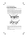
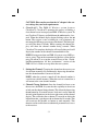
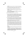
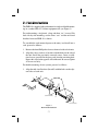
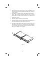
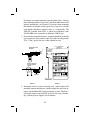
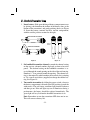
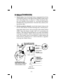
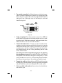
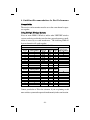
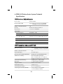
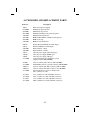
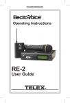
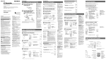
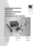
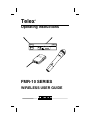
Telex
â
Operating Instructions
Telex
FMR-10
R
A
1
2
3
4
-20
-10
0
+3
RF
CLEAR
SCAN TM
Diversity
Audio
Channel
B
Te
lex
TR
AN
ITT
ER
Tele
-10 x
SM
UH
F
WT
POWE
R
BAT
.
O
N
AUD
IO
FMR-10 SERIES
WIRELESS USER GUIDE
R
Table of Contents
Section
Page
1. Quick System Setup Guide . . . . . . . . . . . . . . . . . . . . . . . 1
2. System Description . . . . . . . . . . . . . . . . . . . . . . . . . . . . . 3
3. Detailed system/component setup instructions . . . . . . . . 4
3.1. FMR-10 Receiver Setup and Operation . . . . . . . . . . 4
3.1.1 Rack Mount Installation . . . . . . . . . . . . . . . . . . . 7
3.1.2 Antenna Placement . . . . . . . . . . . . . . . . . . . . . . . 9
3.2. Handheld Transmitter Setup . . . . . . . . . . . . . . . . . . 11
3.3. Bodypack Transmitter Setup . . . . . . . . . . . . . . . . . 13
4. Guidelines/Recommendations for Best Performance . . 16
5. Troubleshooting Guide . . . . . . . . . . . . . . . . . . . . . . . . . 18
6. Technical Specifications . . . . . . . . . . . . . . . . . . . . . . . . 19
FCC Information . . . . . . . . . . . . . . . . . . . . . . . . . . . . . . 20
Accessories and Replacement Parts. . . . . . . . . . . . . . . . 21
1. Quick System Setup Guide
Receiver Setup
1. Plug power supply cord into the back of the receiver and plug the
power supply into an outlet. The channel display & red/green
“Diversity” light on the receiver front panel should light up.
2. Attach the supplied 1/4 wave antenna’s to the FMR-10 receiver.
Orient the receive antennas angled up and away from each other
(at a 90 degree angle). For specific receiver setup information, refer to section 3.1 for the FMR-10 receiver. Assure that your transmitter(s) are turned OFF.
3. Depress “SET” button on front panel and release when channel
display starts to flash (about 3 seconds). This activates
“ClearScan™” to find an interference free channel for operation.
Note the channel (0 - 9) shown on the receiver front panel channel
display.
4. Connect receiver audio output to mixer or amplifier. Mute or reduce mixer gain.
-1-
Transmitter Setup
1. Open battery compartment, install 9 Volt battery. Make sure to
observe proper battery polarity.
2. Adjust channel setting to match channel number shown on receiver channel display. Replace battery cover.
3. If using bodypack transmitter, plug the microphone into the transmitter connector.
Operating the System
1. Turn transmitter ON via the ON/OFF switch. After a few seconds, the yellow “Tx On” light should illuminate on the receiver
front panel.
2. Turn audio switch to the ON position to the audio.
3. Set mixer amp gain to normal position.
4. Talk/sing into the microphone at a normal volume. You should
hear audio coming out of the system.
5. If the signal is distorted, turn the gain adjust control on the transmitter down. If the signal level is low, you may need to turn the
gain adjust control up.
-2-
2. System Description
The Telex FMR-10 Wireless is a series of 10 channel frequency agile
UHF wireless systems that combine Telex’s legendary quality and
reliability with high value. The transmitters and receivers operate in
the UHF frequency range. The well-designed audio circuitry ensures
excellent signal-to-noise ratio with accurate sound quality.
System Features
· 10 Channel Frequency Agile UHF system operation.
· Featuring “ClearScan™” which makes for quick and easy system
setup.
· Handheld transmitters feature Electro-Voice N/DYM mic elements, for superior sound quality.
· True-diversity system with Posi-Phase™ insures maximum range
and freedom from interference.
· Well-designed companding and audio circuitry insures high signal-to-noise ratio and excellent sound quality.
· Receivers may be rack-mounted with included hardware.
· FMR-10 output via 3-pin XLR-type balanced mic level connector.
-3-
3. Detailed Setup Instructions
3.1 FMR-10 Receiver Setup & Operation
1. Place the receiver where there is a clear line of sight to the area
where the transmitter will be used.
2. Attach either the supplied 1/4-wave antennas or two remotely
mounted antennas to the antenna connectors on the rear panel of the
FMR-10. Be sure and tighten the connectors securely. If the supplied
1/4-wave antennas are used, they must be oriented at a 90o angle as
shown in Figure 2. Unlike other diversity wireless systems, two
antennas are required for the FMR-10 to operate correctly.
SET ANTENNAS
AT 90 DEGREES
CHANNEL
SET
BUTTON
Telex
CHANNEL
DISPLAY
DIVERSITY
LIGHTS
RF METER
FMR-10
R
A
1
2
3
4
-20
-10
0
+3
RF
CLEAR
SCAN TM
Diversity
Audio
Channel
B
AUDIO METER
LOCK OUT INDICATOR
Figure 1 FMR-10 Front View
BALANCED
AUDIO
OUTPUT
Antenna
Balanced
Mic Level
Output
Made
in
U.S.A.
Antenna
Telex
FC
C
Power
12-15 V AC/DC
700 mA
R
FMR-10
Canada
Patent Pending
POWER
JACK
Squelch
Tested to Comply
with FCC Standards
llll
llll
llll
llll lllllll llll
SQUELCH
CONTROL
Figure 2 FMR-10 Rear View
3. Connect the power supply cord to the receiver. Plug the power
supply into an AC outlet. Confirm that the receiver is ON by
checking for the lighted channel display and diversity led’s on the
front panel.
NOTE: Upon power-up, the receiver will return to the channel it
was set to when it was turned off.
-4-
CAUTION: Please make sure that the AC adapter is the correct voltage for your local requirements.
4. ClearScan™: The FMR-10 Wireless system features
ClearScan™. ClearScan™ automates the process of finding a
clear channel to use in setup of your FMR-10 Wireless system. To
use ClearScan™, depress and hold down the set button for 3 seconds. When the channel display begins flashing release the set
button. The receiver is now searching for a clear frequency by
measuring the RF energy present on each channel. The entire process will take about 5 seconds. While scanning, the channel display will show the channel number being scanned. When
ClearScan™ is complete, the display will stop flashing and it will
display the number of the channel recommended for use.
NOTE: If using more than one FMR-10 system, set up ONE system at a time. Turn on the transmitter for the first system, before
using ClearScan™ to set up the second. Please see the “Guideline/Recommendations for best performance” section of the
FMR-10 User’s Guide to set up more than two systems.
5. Setting the Channel: Changing the channel on the receiver can
also be done manually. By momentarily depressing the set button, the channel number is increased by one.
NOTE: when the system is turned off, the channel number is
saved in non-volatile memory. When the receiver is turned on, it
will return to the same channel number.
6. Channel Change Lock-out: Once the channel has been set on
the receiver, the FMR-10 system has the capability to deactivate
or lock-out the channel change button. This is done by depressing
the set button for 10 seconds or more. Lock-out is active when the
decimal point illuminates in the lower right corner of the channel
display. This will defeat the set button. To override or defeat the
lockout function, again depress the set button for 10 seconds. This
will reactivate the channel set button to work normally. This
function can be useful where unauthorized personnel have access
to the receiver.
-5-
NOTE: If the system is in “lock-out”, ClearScan™ will not function.
7. Make sure the gain setting is muted or turned down on the mixer
or amp channel you will connect the wireless system to.
8. Plug the audio cable (not supplied) into the output connector.
NOTE: The 3-pin XLR-type connector output level is fixed, and
cannot be adjusted.
Now refer to details located in the FMR-10 User’s Guide on
how to set up the transmitter.
Once the Transmitter has been set-up, and turned on...
9. Speak or sing loudly into the microphone and observe the Audio
level meter on the receiver. Adjust the gain control on the transmitter to prevent over or under modulation. The gain should be
adjusted so that the signal peaks are no more than -10dB and that
there is at least -20dB or audio level meter indication.
10. “Walk” the expected area of use to check for dropouts or interference. To minimize the potential for dropouts or interference,
please observe good antenna placement. When the transmitter is
turned on, the RF meter on the receiver should be illuminated in
the green range to verify it is receiving a strong signal.
11. Adjust the squelch control if necessary. The squelch control on
the back of the receiver may be adjusted to effectively increase
range or to reduce interference. The factory setting is at a midpoint, which should be suitable for most situations. To effectively
increase range, turn the control counter-clockwise until you hear
noise or interference, then, turn the squelch clockwise until the
noise is muted. To reduce interference, turn the control clockwise.
NOTE: If the squelch is being adjusted, the transmitter should be
turned off.
CAUTION! Increasing the range will make the system more
susceptible to outside interference! Reducing interference
will also effectively decrease the range, which will make the
system more susceptible to dropouts.
-6-
3.1.1 Rack Mount Installation
The FMR-10 is supplied with rack mounts for single and double mounting in a standard EIA 19”/ 483mm equipment rack (see Figure 3).
For rack mounting a single unit, a long and short “ear” are used. For
dual side-by-side mounting, use the short “ears” and the mid sized
brackets from two FMR-10 as shown.
To assemble the rack mount adapters to the unit(s) and install into a
rack, proceed as follows:
1. Remove the front Phillips head screws from each side of each unit.
2. Align the correct rack ear or bracket with the holes on the side of
the unit. Install the previously removed screws. Insert an additional screw (provided in the parts pack) into the remaining hole.
Repeat this step for the opposite side of the unit. Be sure to tighten
all screws securely.
For double mounting of two systems, proceed as follows:
1. Align the mid-sized brackets (Item #2) with the holes on the adjacent sides of each unit.
1
REMOVE SCREWS
(TYPICAL 4 SIDES)
6
CLE
SC AR
AN
5
Chan
nel
Divers
ity
1
AUD
IO
2
3
4
6
FM
R-1
0
3
CLE
SC AR
AN
2
Chan
nel
Divers
ity
1
AUD
IO
2
3
4
(TYPICAL BOTH SIDES)
5
FM
R-1
0
1
6
4
(TYPICAL ALL SIDES)
Figure 3
Rack Mount Installation
-7-
2. Install the previously removed screws. Insert an additional screw
(provided in the parts pack) into the remaining holes. Tighten all
screws securely.
3. Place the two assemblies side-by-side with the mid brackets together. (The left bracket should fit above the right so that the
countersinks are visible). Install 4 flat-head screws (Item #5) and
tighten them securely.
4. Attach the antenna connectors to the brackets.
5. Attach the supplied extension cables from the rack connectors to
the antenna connections on the back of the receiver.
6. Place the assembly into the rack enclosure and insert 4 #10-32 x
3/8” Phillips pan head screws (supplied) in each corner of the rack
ears and secure to the enclosure. Some rack enclosures require
metric screws which are not supplied.
Ch
ann
el
Div
ersi
ty
AU
DIO
FM
R-1
0
Ch
ann
el
Div
ersi
ty
AU
DIO
Figure 4
-8-
FM
R-1
0
3.1.2 Antenna Placement
For any wireless system to perform correctly, strong RF signals are
mandatory. To maximize signal strength, good antenna placement
must be utilized. Although some situations prohibit perfect antenna
placement, here are some guidelines:
1. The antennas should be placed in a location with a clear signal
path to the transmitter. Walls, ceilings, metal objects, equipment
racks, etc. are all signal barriers that will reduce range and performance. Generally speaking, placing the receiver at an elevated location can help increase range and signal strength.
Figure 5
1/2-Wave antenna for Remote Mounting
Figure 6
2. If the receiver is rack-mounted, external antennas are necessary. Do not rack mount the FMR-10 with the antennas
mounted directly on the back of the unit. This will severely
decrease the range and performance of the system.
If the FMR-10 is rack-mounted, make sure the antennas are
front-mounted (following the directions noted above). If antennas are mounted remotely from the chassis, the 1/4-wave antennas supplied with the receiver cannot be used. 1/2-wave antennas
are a necessity if the antennas are remote-mounted and can provide better performance when used with the rack mount.
-9-
If antennas are remote-mounted, separating them 6 feet (1.8m) or
more and keeping them at least 2 feet (.6m) from other barriers will
improve performance (see Figure 8). If you are remote mounting
the antennas and require strong signal over a large area, consider
using highly directional antennas such as a log-periodic. The
ALP-450 available from Telex is tuned for frequencies from
450-900 MHz and can provide an additional 5 dB of gain.
3. If you remote-mount the antennas, attention should be paid to the
type and quality of the antenna cable. For cable runs longer than
25-ft. (7.6m), special low-loss cables should be used.
MICROPHONE STAND
MOUNTING
6 FT (2 METERS)
MINIMUM
DISTANCE
2 FT (60 CM)
MINIMUM
DISTANCE
Telex
FMR-10
R
A
CLEAR
SCAN TM
1
2
3
4
-20
-10
0
+3
RF
AUDIO
B
Telex
FMR-10
R
A
CLEAR
SCAN TM
Diversity
Channel
1
2
3
4
-20
-10
0
+3
RF
Diversity
Channel
AUDIO
B
BRACKET SHOULD BE
AT TOP OF MOUNTING
SURFACE.
SIDE
MOUNTING
Figure 7
Figure 8
4. If multiple wireless systems are being used, a multi-coupler will
minimize antenna interference. A multi-coupler has one set of antennas and distributes RF signal to multiple systems. The Telex
will supply antenna signal and DC power to 4 systems, eliminating 3 external power supplies and 6 antennas.
-10-
3.2 Handheld Transmitter Setup
1. Insert battery. Slide open the hinged battery compartment cover
by placing your thumb on the indents of the battery door (at the
bottom of the transmitter) and gently pushing down (see Figure
9). Insert the battery, terminal end first, into the compartment,
with the smaller positive terminal to the right.
SLIDE BATTERY DOOR BACK
Telex
R
Telex
e
lex
R
GAIN
ADJUST
SWING DOOR UPWARD
8
7
Telex
6
R
8
7
9
6
POWER
SWITCH
9
0
5
1
2
3
4
MIC
SWITCH
Figure 9
0
5
1
2
3
4
CHANNEL SET
SWITCH
Figure 10
2. Set handheld transmitter channel to match the channel setting
on the receiver (channel number displayed on front of receiver
panel). The channel setting on the handheld transmitter is accessed through the round opening on the side of the mic housing.
Numbers 0 - 9 are printed around the opening. The channel setting is determined by which number the arrowed slot is pointing
to. Use a small screwdriver (supplied) to change the channel setting. See Figure 10.
3. Turn on the transmitter by sliding the power switch (closest to
the battery compartment) forward to the ON position (toward the
windscreen). The red battery condition light should flash once
and then go out. If the red light stays on or illuminates during a
performance, the battery should be replaced immediately. The
green light will stay lit when the handheld transmitter is on.
Note: Remember to turn the transmitter OFF when not in use.
This will conserve battery life.
-11-
4. Verify Reception. When the transmitter is turned on: (FMR-10)
the RF meter will illuminate, indicating that the receiver is picking up the signal. If this does not happen, make sure that the transmitter and receiver are set to the same channels.
5. Unmute the audio by sliding the audio switch (immediately below the mic element) towards the windscreen. Speak or sing into
the microphone and you should hear your voice through the PA /
sound system.
6. Adjustment of the transmitter audio gain - if necessary. The
transmitter audio gain is set to a mid level which should be suitable for most situations. However, for loud or soft speakers or
singers, an adjustment may be necessary. First, speak or sing into
the microphone and listen closely. If the gain is too high, you will
hear distortion, and if the gain is too low, the signal will be low. In
either situation, an adjustment may be necessary.
To adjust the transmitter gain, gently insert the provided screwdriver (or other 3/32-in./2.4mm screwdriver) into the hole near
the head of the transmitter (see Figure 12). Turn lightly until the
screwdriver tip drops into the slot in the level control. Gently turn
counterclockwise until the control stops (the mic output is attenuated but not “off”). Slowly turn the mic-level control up while listening to the audio. If the audio becomes distorted, turn the mic
level control down (counter-clockwise) about 1/8 turn.
Note: Operate with the transmitter audio gain set as high as possible without distortion, for the best signal to noise ratio.
7. Test performance. Check to see that the RF meter on the
FMR-10 receiver is illuminated, an indication that the receiver is
picking up the signal. Then, “walk” the intended area of use and
make sure that there are no barriers to reception or sources of interference. If problems are encountered, see Troubleshooting
Guide.
-12-
3.3 Bodypack Transmitter Setup
1. Insert battery. Open the hinged battery compartment by placing
your thumb or finger on the indent labeled OPEN on the battery
door and pushing down, see Figure 11. When inserting the battery, pay attention to the polarity (+/-) and insert the terminals
into the battery compartment first. Close the battery door by sliding the door shut.
2. Set the transmitter channel to match the channel setting on the
receiver. The channel switch on the bodypack is located just underneath the battery door, and to the right of the indent labeled
OPEN. Note the channel number label (0-9) surrounding the
opening. The bodypack channel must be set to the same number
as the receiver channel, which is displayed on the receiver front
panel. The channel setting is determined by which number the
arrowed slot is pointing to. Use a small screwdriver (supplied)
to change the channel setting.
BELT CLIP MAY BE TURNED
90 DEGREES BY REMOVING
SCREW AND REINSTALLING
HERE.
GAIN
ADJUSTMENT
CHANNEL
SWITCH
DOOR OPENED
BUT NOT
SWUNG UPWARD
SWING DOOR
UPWARD TO
ACCESS BATTERY
COMPARTMENT
TO OPEN BATTERY DOOR
PRESS ARROW WITH INDEX
FINGER AND PULL DOWN WITH
THUMB AND MIDDLE FINGER
Figure 11
Channel Switch
-13-
3. Turn on the transmitter by sliding the power switch to its on position. Check the condition of the battery by watching the light
below the power switch. The red battery light should flash once
and then go out. If the light stays on, the battery is weak and
should be replaced.
ANTENNA
POWER
SWITCH
AUDIO
SWITCH
POWER
O
N
MIC
CABLE
ENTRY
AUDIO
O
F
F
BAT.
BATTERY LIGHT
Figure 12
4. Verify reception. When the transmitter is turned on: (FMR-10)
the RF meter will illuminate, indicating that the receiver is picking up the signal. If this does not happen, make sure that the transmitter and receiver are set to the same channels.
5. Connect the audio source. If using a lavalier or headworn microphone, insert the connector on the end of the mic wire, into the
connector on the bodypack. If using a lavalier mic, use the clip to
attach the mic to the users clothing. If using the headworn mic,
place the headset on the user’s head, positioning the mic at the
corner of their mouth.
Note: Keep the audio muted while plugging in and adjusting
the microphone or source. Placement of lavalier and headworn
microphones will noticeably change the sound quality, so some
testing with the user is necessary. An important point to remember,
the closer to the sound source, the stronger or louder the signal.
6. Unmute the audio, by sliding the large AUDIO switch located on
the bodypack, to the ON position. Speak or sing into the microphone
and you should hear your voice through the PA / sound system.
7. Listen carefully to the audio and be sensitive of overload distortion and low gain.
-14-
8. Adjust the transmit gain if necessary. Gently insert the provided screwdriver or other 3/32-in. 2.4mm screwdriver into the
gain adjustment located at the top edge of the battery compartment under the door (see Figure 11). The door has to be opened
but not swung upward to make adjustments. Turn lightly until the
screwdriver tip drops into the slot on the level control. Gently turn
the control counterclockwise until the control stops (the audio
output is attenuated but not “off”). Slowly turn the audio level
control clockwise while listening to audio; if the audio becomes
distorted, turn the mic level control counter-clockwise about 1/8
turn.
9. Test performance. Check to see that the RF meter on the
FMR-10 receiver is illuminated, an indication that the receiver is
picking up the signal. Then, “walk” the intended area of use and
make sure that there are no barriers to reception or sources of interference. If problems are encountered, see Troubleshooting
Guide.
10. Clip the bodypack to the user’s belt or pocket. The bodypack
can be positioned horizontally or vertically by moving the belt
clip attachment. This is done by removing the belt clip attachment
screw, rotating the clip to the desired position, and replacing the
screw.
-15-
4. Guidelines/Recommendations for Best Performance
Compatibility
The receiver and transmitter must be set to the same channel to operate together.
Using Multiple Wireless Systems
If two or more FMR-10 Wireless and/or other VHF/UHF wireless
systems are being used in the same location, proper frequency coordination is necessary to avoid interference. The following FMR-10
System channels will work together:
FMR-10 FREQUENCIES
LOW BAND
Channel
Number
0
1
2
3
4
5
6
7
8
Compatible Systems
within Low Band
✔
✔
✔
9
✔
✔
✔
✔
Operating
Frequency
707.45
708.25
709.25
710.05
711.65
713.85
715.25
718.85
720.50
TV
Channel
53
53
53
54
54
54
54
55
55
Channel
Number
0
1
2
3
4
5
6
7
8
721.45
55
9
TV
Channel
56
56
56
57
57
57
58
58
58
Channel
Number
0
1
2
3
4
5
6
7
8
58
9
HIGH BAND
Channel
Number
0
1
2
3
4
5
6
7
8
Compatible Systems
within High Band
✔
✔
✔
Operating
Frequency
725.45
726.25
727.25
728.35
729.65
732.65
734.05
736.45
737.05
9
✔
737.85
✔
✔
✔
Compatible
Systems within
High & Low Band
✚
✚
✚
✚
✚
✚
✚
✚
✚
✚
Contact your dealer or Telex for assistance, if you are planning to add
more wireless systems to be operated simultaneously in the same location.
-16-
Multiple System Setup & ClearScan™
ClearScan™ is most useful for finding operating frequencies for situations where no more than 2 systems will be used simultaneously.
When setting up more than 2 systems, use ClearScan™ to choose the
first channel of operation. Set up subsequent systems following the
channel groupings listed above in the “Using Multiple Wireless Systems” section.
Potential Sources of Interference
There are many potential sources of interference for your wireless
system. Any electronic product that contains digital circuitry including digital signal processors (reverb/multi-effects units), electronic
keyboards, digital lighting controllers, CD players and computers, all
emit RF energy that can adversely affect the performance of your
wireless system. It is always best to place your receiver as far away
from these devices as possible to minimize this potential source of
problems.
-17-
Battery Recommendations
Fresh 9-volt alkaline batteries from a quality manufacturer will yield
the best performance from your FMR-10 transmitters. Rechargeable
8.4-volt Ni-cad batteries can be used, but will yield much shorter operational time.
When the transmitter switch is turned on, the red battery light will
flash once if the battery is good. If the light does not flash or stays lit
continuously, the battery is weak or dead. If the light comes on during
use, the battery is weakening and should be replaced as soon as possible.
If sound quality degrades during use, it may be the result of a weakening battery.
Receiver and Antenna Placement
Do not place the receiver near a large metal object or surface.
Locate the receiver as close as possible to the area where the Transmitter user will be working. Ideally, position the receiver so that the
transmitter is within site of the receiver.
When using multiple systems, do not allow antennas to cross or touch
each other.
-18-
5. Troubleshooting Guide
Problem
Possible Causes
Solutions
No audio & no lights on
receiver
Receiver is off
Make sure that power supply is properly connected and providing power to
the receiver
No audio & no Tx ON
light on receiver
Transmitter is off
Turn on transmitter power switch
No (or dead) battery in
transmitter
Insert fresh battery in transmitter
Faulty battery contacts
in transmitter
Clean contacts
Transmitter audio switch
is off (signal is muted)
Turn on transmitter audio switch
Receiver audio cable is damaged or disconnected
Connect, repair, or replace cable
G a i n not s uf f i c i e nt
mixer/preamp/amp input.
Increase mixer/preamp/amplifier gain
setting
No audio
Low audio signal
Distorted audio signal
Interference
Short range or drop-outs
on
Gain set too low (or muted) on
mixer/preamp/amplifier
I nc r e a s e
ga i n
s e t t i ng
mixer/preamp/amplifier
R e c e i ve r a udi o t oo l ow
(1/4”/6.4mm output)
Increase receiver audio volume setting
Transmitter audio level too low
Increase transmitter audio gain setting
Transmitter audio level too high
(overloading transmitter circuit)
Decrease transmitter audio gain setting
Receiver audio set too high (1/4”
6.4mm output)
Decrease receiver audio level setting
Battery level low in transmitter
Insert fresh battery in transmitter
Another wireless product in the
immediate area, operating on the
same frequency, or on a frequency that mixes with another
RF signal (such as a TV broadcast transmitter).
Change operating frequency. If interference is weak, keep transmitter on at
all times (to override interfering signal) whenever receiver is on.
Receiver placed too close to a
digital signal processor or similar device.
Move receiver to a different location
Strong electromagnetic field
from stage lighting or other
source near the transmitter or receiver, which may be producing
RF noise on or near the operating frequency.
Change operating frequency. Repair or
remove source of interference. Move
receiver to a different location.
RF reflective metal obstacles
between transmitter & receiver.
Move the obstacles, or reposition the
receiver
Poorly oriented beltpack antenna
Reorient bodypack so that antenna is
positioned vertical (up and down) and
facing receiver, if possible
Faulty receiving antenna system
Reposition antennas or receiver
-19-
on
6. FMR-10 Wireless Series System Technical
Specifications
UHF Receivers: FMR-10 Receiver
Receiver Type
Synthesized PLL
Frequency Range (RF)
Selected Frequencies between 710-866 MHz
(depending on Country of Operation)
Number of Selectable Channels
10
Diversity
True Diversity with Secure-Phaseä
RF Sensitivity
< .8 uV for 12 dB SINAD
Audio Output,
Frequency Response
50-15 kHz +/- 2 dB
Audio Output, Balanced (XLR)
-20 dBV (600 Ohm Load)
Audio Output, Unbalanced
(1/4”/6.4mm, NRU only)
adjustable 8 mv to 0.775V RMS (100 K ohm load)
Distortion (THD)
Less than 0.5%
Signal-to-Noise Ratio
>94 dB
Dynamic Range
100 dB
UHF Transmitters: WT-10 and HT-10D
RF Frequency Range
Selected Frequencies between 710 - 866 MHz
(depending on Country of Operation)
Number of Selectable Channels
10
Radiated RF Output
10-15 mW typical
Microphone Element HT-100 handheld
EV N/D 767a cardioid N/DYM dynamic
TA4F Connector Wiring:
Pin 1: Ground; Pin 2: Mic Input;
Pin 3: +5 volt bias; Pin 4: +5 volt bias fed
through a 3 K ohm resistor for 2-wire electrets
Audio Gain Adjustment Range
40 dB beltpacks, 26 dB handhelds
Battery Life
8 - 10 hours with 9-Volt alkaline
Bodypack Antenna
flexible external 1/4 wave
Handheld Mic Antenna
internal 1/2 wave
Size (Handheld transmitter)
10. 13 in. (257mm) long
Size (Bodypack transmitter) HxWxD
4.5 in. (114mm) x 2.6 in. (66mm)
x 1.3 in. (32mm) (no antenna)
-20-
FCC INFORMATION
The TELEX Receiver FMR-10 is authorized under Part 15 of
the Federal Communication Commission.
The Telex WT-10 and HT-10D Transmitters are type Accepted under United States Federal Communications Commission Part 74.
Licensing of Telex equipment is the user’s responsibility
and licensability depends upon the user’s classification,
user’s application, and frequency selected. Telex strongly
urges the user to contact the appropriate telecommunications authority for any desired clarification.
CAUTION: Any changes or modifications made to the above
equipment could void the user’s authority to operate the
equipment.
-21-
ACCESSORIES AND REPLACEMENT PARTS
Order No.
Description
450131
63850006
63850007
64277000
57013001
70925001
70928001
57013001
450124
870343
71081001
71081002
730139
730140
730103
71253000
Plastic belt clip for bodypack
WLM-50 tie clip-horizontal
WLM-50 tie clip-vertical
WLM-50 omnidirectional lapel microphone
WLM-50 foam windscreen
ELM-22 MicroMini™ omnidirectional lapel mic
ELM-22 mic clip
ELM-22 foam windscreen
Spring-adjusted handheld mic stand adapter
Deluxe handheld mic stand adapter
Rack-mount kit - Single
Rack-mount kit - Double
120-volt power supply (US/Canada type)
230-volt power supply (EURO type)
230-volt power supply (UK type)
UAD-2 Antenna/power distribution system
(supplies 4 units) (600-780 MHz)
879010
71147000
870658-5
870658-6
71138000
1/4-wave antenna with connector (668-746 MHz)
ALP-450 Directional log periodic antenna (450-900 MHz)
1/2-wave antenna with TNC connector (690-725 MHz)
1/2-wave antenna with TNC connector (725-760 MHz)
Universal bracket for 1/2-wave antenna with
10 ft. (3.05m) coax cable
71151025
71151050
71151075
71151100
25 ft. (7.62m) coax cable with TNC connectors
50 ft. (15.24m) coax cable with TNC connectors
75 ft. (22.86m) coax cable with TNC connectors
100 ft. (30.48m) coax cable with TNC connectors
-22-
R
Telex Communications Inc., 12000 Portland Ave. South, Burnsville, MN 55337
(952) 884-4051, (800) 828-6107, Fax: (952) 887-9212
PN 803341
May 2001