1
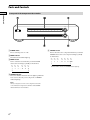
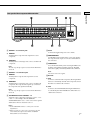
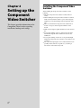
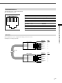
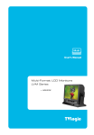
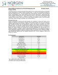
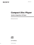
3-198-136-11(1) Component Video Switcher Installation Manual Owner’s Record The model and serial numbers are located on the rear panel. Record the model and serial numbers in the spaces provided below. Refer to them whenever you call upon your Sony dealer regarding this product. Model No. CAV-CVS12ES 2007 Sony Corporation Serial No. WARNING To reduce the risk of fire or electric shock, do not expose this apparatus to rain or moisture. To reduce the risk of fire or electric shock, do not place objects filled with liquids, such as vases, on the apparatus. This symbol is intended to alert the user to the presence of uninsulated “dangerous voltage” within the product’s enclosure that may be of sufficient magnitude to constitute a risk of electric shock to persons. This symbol is intended to alert the user to the presence of important operating and maintenance (servicing) instructions in the literature accompanying the appliance. WARNING This equipment has been tested and found to comply with the limits for a Class B digital device, pursuant to Part 15 of the FCC Rules. These limits are designed to provide reasonable protection against harmful interference in a residential installation. This equipment generates, uses, and can radiate radio frequency energy and, if not installed and used in accordance with the instructions, may cause harmful interference to radio communications. However, there is no guarantee that interference will not occur in a particular installation. If this equipment does cause harmful interference to radio or television reception, which can be determined by turning the equipment off and on, the user is encouraged to try to correct the interference by one or more of the following measures: – Reorient or relocate the receiving antenna. – Increase the separation between the equipment and receiver. – Connect the equipment into an outlet on a circuit different from that to which the receiver is connected. – Consult the dealer or an experienced radio/ TV technician for help. US CAUTION You are cautioned that any changes or modifications not expressly approved in this manual could void your authority to operate this equipment. Important Safety Instruction 1 2 3 4 5 6 7 Read these instructions. Keep these instructions. Heed all warnings. Follow all instructions. Do not use this apparatus near water. Clean only with dry cloth. Do not block any ventilation openings. Install in accordance with the manufacturer’s instructions. 8 Do not install near any heat sources such as radiators, heat registers, stoves, or other apparatus (including amplifiers) that produce heat. 9 Do not defeat the safety purpose of the polarized or grounding-type plug. A polarized plug has two blades with one wider than the other. A grounding type plug has two blades and a third grounding prong. The wide blade or the third prong are provided for your safety. If the provided plug does not fit into your outlet, consult an electrician for replacement of the obsolete outlet. 10 Protect the power cord from being walked on or pinched particularly at plugs, convenience receptacles, and the point where they exit from the apparatus. 11 Only use attachments/accessories specified by the manufacturer. 12 Use only with the cart, stand, tripod, bracket, or table specified by the manufacturer, or sold with the apparatus. When a cart is used, use caution when moving the cart/ apparatus combination to avoid injury from tip-over. 13 Unplug this apparatus during lightning storms or when unused for long periods of time. 14 Refer all servicing to qualified service personnel. Servicing is required when the apparatus has been damaged in any way, such as power-supply cord or plug is damaged, liquid has been spilled or objects have fallen into the apparatus, the apparatus has been exposed to rain or moisture, does not operate normally, or has been dropped. Welcome! Thank you for purchasing the Component Video Switcher. Before operating the unit, please read this manual thoroughly and retain it for future reference. Table of Contents Chapter 1 Getting Started Features 4 Unpacking 5 Parts and Controls 6 Chapter 2 Setting up the Component Video Switcher Installing the Component Video Switcher 8 Hooking up the Component Video Switcher 10 Chapter 3 Other Information Precautions 12 Troubleshooting 13 Specifications 14 US Chapter 1 Getting Started This chapter provides information on the features, parts, and controls of the Component Video Switcher. US Features You can control up to twelve video sources in up to twelve zones (e.g., rooms or areas) with this CAV-CVS12ES Component Video Switcher. The Component Video Switcher allows you to: – Distribute HD video signals in up to twelve zones. – Up-convert up to four composite video signals to component video signals for higher quality. – Control the source component in synchronization with the CAV-M1000ES via RS-232C commands. – Control the source component via IR control signal. – Transmit video signals throughout the house using a CAT5 (Category 5e) cable. Unpacking Getting Started The CAV-CVS12ES Component Video Switcher includes the following: CAV-CVS12ES Component Video Switcher AC power cord Installation Manual (this manual) Rack-mount brackets (2) US Parts and Controls Getting Started Front panel of the Component Video Switcher ZONE 1 2 3 4 5 6 7 8 9 10 11 12 POWER SOURCE 1 2 3 4 5 6 POWER switch Press to turn the power on or off. ZONE indicator The selected zone number lights up. 7 8 9 2 3 … 10 11 12 SOURCE indicator The source number selected for the zone lights up. When the zone does not select any source component, no SOURCE indicator lights up. Note When you assign two or more source components to the same source number, the assigned source numbers of the SOURCE indicator blink as an error indication. US 11 12 SOURCE selector Turn to select the source component. Each time you turn the SOURCE selector, the source component changes cyclically as shown below. 1 ZONE selector Turn to select the zone. Each time you turn the ZONE selector, the zone changes cyclically as shown below. 1 10 2 3 … 10 11 12 OFF When the OFF is selected, no SOURCE indicator lights up. SOURCE 1 IN OUT SOURCE 2 IN OUT SOURCE 3 IN SOURCE 4 OUT IN OUT SOURCE 5 IN OUT Getting Started Rear panel of the Component Video Switcher SOURCE 6 IN OUT SOURCE 7 IN OUT SOURCE 8 IN SOURCE 9 SOURCE 10 SOURCE 11 SOURCE 12 OUT Y IN OUT IN ASSIGNABLE PB S9 PR OUT ASSIGNABLE VIDEO OUT VIDEO OUT VIDEO OUT VIDEO OUT VIDEO OUT VIDEO OUT VIDEO OUT VIDEO OUT VIDEO OUT VIDEO OUT VIDEO OUT VIDEO OUT ZONE 2 ZONE 3 ZONE 4 ZONE 5 ZONE 6 ZONE 7 ZONE 8 ZONE 9 ZONE 10 ZONE 11 ZONE 12 S10 SOURCE 1 ~ 8 connection jacks a) VIDEO IN An RCA jack for component video input from a source component. b) VIDEO OUT An RCA jack for connecting a video source to another local component. Note The video loop-through output is not active when the Main Unit is turned off. SOURCE 9 ~ 12 connection jacks a) VIDEO IN An RCA jack for composite video input from a source component. b) VIDEO OUT An RCA jack for connecting a video source to another local component. The composite video signal is up-converted to the component video signal automatically. Note The video loop-through output is not active when the Main Unit is turned off. IN OUT ASSIGNABLE S11 IN OUT ASSIGNABLE ~ AC IN S12 RS-232C IR REMOTE ZONE 1 IN AUX CAV AC IN Connects the supplied AC power cord to AC IN. ZONE VIDEO OUT A CAT5 RJ45 connector that sends a source video signal to the component video input of a zone. Use a CAT5 cable for the connection. IR REMOTE IN A 3.5 mm monaural mini jack for receiving the SIRCS code from the connected IR-controlled component. The Main Unit can be equally controlled by the RS-232C commands. Note The remote control is not supplied. RS-232C a) AUX Connects to other RS-232C components, allowing the Main Unit to be controlled by other RS-232C components. Use an RS-232C cross cable for the connection. b) CAV Connects to the CAV-M1000ES, allowing the Main Unit to be controlled by the CAV-M1000ES. Use an RS-232C cross cable for the connection. ASSIGNABLE switch for SOURCE 9 ~ 12 Assign the source component connected to source 9 ~ 12 to source 1 ~ 8. For example, when the SOURCE 9 ASSIGNABLE switch is set to “1”, the source 9 video signal is distributed to the zone selected for source 1. Notes Set the ASSIGNABLE switch to “0” when you do not use the assign function. When you assign two or more source components to the same source number, the assigned source numbers of SOURCE indicator blink as an error indication. US Chapter 2 Setting up the Component Video Switcher This chapter provides information on the Component Video Switcher regarding installation, hookups and settings. US Installing the Component Video Switcher When installing the Component Video Switcher, note the following: Place the Component Video Switcher on a flat and level surface. When installing the Component Video Switcher in a cabinet, make sure the back of the cabinet is open to allow adequate ventilation, prevent heat buildup, and prolong the life of the unit. Place a board under the Component Video Switcher if it is located on a carpet to allow adequate ventilation on the bottom. Make sure the weight is equally distributed on each of its four feet. Do not place anything on the top of the Component Video Switcher that might block the ventilation holes and cause malfunction. Do not place anything on the front or rear panel that might damage the Component Video Switcher’s control buttons and connectors. Use caution when placing the unit on surfaces that have been specially treated (with wax, oil, polish, etc.) as staining or discoloration of the surface may result. Using rack-mount brackets You can also mount the Component Video Switcher into a rack. Make sure that you measure the space needed before mounting. 1 Detach the four feet of the Component Video Switcher. 2 Detach the six screws attached to the Component Video Switcher as shown below. Rack-mount bracket (supplied) Screws Screws ZONE 1 2 3 4 5 6 7 8 9 10 11 12 1 2 3 4 5 6 7 8 9 10 11 12 POWER SOURCE Rack Rack Screws (not supplied) Screws (not supplied) Notes Screws 3 Install the rack-mount brackets onto the Component Video Switcher with the six screws detached in step 2 as shown below. Make sure that the rack-mount brackets are installed securely. Rack-mount bracket (supplied) Use the M4 × 11/32 inch (8mm) screws (attached to the Component Video Switcher) for installing the rack-mount brackets onto the Component Video Switcher. In case the screws are missing, use M4 screws with a maximum diameter of 1/2 inch (12mm). Use screws with a minimum diameter of 3/16 inch (4mm) when you mount the Component Video Switcher into the rack. Make sure you check the rack manufacturer’s specifications before you mount the Component Video Switcher into the rack. This is to ensure mechanical stability. This Component Video Switcher requires 2U height when you mount the Component Video Switcher on a standard rack. Screws US Setting up the Component Video Switcher 4 Mount the Component Video Switcher into the rack as shown below. Make sure that the Component Video Switcher is installed securely. Hooking up the Component Video Switcher Before hooking up the Component Video Switcher, be sure the AC power cord is unplugged. Refer to the illustration below for the connection. Zone 1 ~ 12 Display Audio/Video Source 1 ~ 8 Audio/Video Source 9 ~ 12 (VHS, etc.) Component Video Component Video Balun CAV-CVB1 Composite Video CAT5 cable Component Video cable CAV-CVS12ES Setting up the Component Video Switcher RS-232C cable Keypad Audio L/R Speaker Audio L/R CAV-M1000ES CAV-M1000ES The CAT5 cable can extend up to 300 feet. 10US RS-232C cable Speaker CAT5 RJ45 Video Pinout The CAT5 RJ45 pinouts use the T568B standard. Refer to the illustration below. Pinout Wire color BLUE/Pb (R) White/Orange Pin 2 BLUE/Pb (T) Orange Pin 3 GREEN/Y (R) White/Green Pin 4 GND Blue Pin 5 +11V White/Blue Pin 6 GREEN/Y (T) Green Pin 7 RED/Pr (R) White/Brown Pin 8 RED/Pr (T) Brown Setting up the Component Video Switcher Pin 1 CAT5 cable Before installation, be sure to verify the CAT5 wiring connection is correct. Use Category 5e or Category 6 cable. RJ45 connector Wire color White/Orange Orange White/Green Blue White/Blue Green White/Brown Brown Pin No. 1 2 3 4 5 6 7 8 Wire color White/Orange Orange White/Green Blue White/Blue Green White/Brown Brown Pin No. 1 2 3 4 5 6 7 8 CAT5 cable RJ45 connector 11US Chapter 3 Other Information This chapter provides additional information that will help you understand and maintain your system. Precautions On safety Should any solid object or liquid fall into the cabinet, unplug the Component Video Switcher and have it checked by a qualified service technician before operating it any further. On power sources Before operating the unit, check that the operating voltage of the unit is identical to that of your local power supply. The operating voltage is indicated on the nameplate on the back of the unit. If you are not going to use the unit for a long time, be sure to disconnect it from the AC power source. To disconnect the lead, grasp the plug itself; never pull the cord. Install this system so that the power cord can be unplugged from the wall socket immediately in the event of trouble. On placement Place the unit in a location with adequate ventilation to prevent heat build-up in the Component Video Switcher. Do not place the unit on a soft surface such as a rug that might block the ventilation holes on the bottom. Do not place the unit in a location near heat sources, or in a place subject to direct sunlight, excessive dust, or mechanical shock. On cleaning Clean the cabinet, panel, and controls with a soft cloth slightly moistened with a mild detergent solution. Do not use any type of abrasive pad, scouring powder, or solvent, such as alcohol or benzine. On operation If the system is brought directly from a cold to a warm location, moisture may condense on the surface of the unit or inside the unit. Should this occur, the system may not operate properly. In this case, turn off and leave the system until the moisture evaporates. Do not use the system until the moisture evaporates, otherwise it may cause a malfunction. If you have any questions or problems concerning the Component Video Switcher, please consult your nearest Sony dealer. 12US Troubleshooting If you experience any of the following difficulties while using the Component Video Switcher, use this troubleshooting guide to help you to remedy the problem. Should any problem persist, consult your nearest Sony dealer. There is no picture, or an unclear picture appears on the TV screen or monitor. Select the appropriate input on the Main Unit. Set your TV to the appropriate input mode. Move your TV away from the audio components. The picture does not appear properly. Check that the Component Video Switcher is connected correctly. For details on how to make the connection, refer to “Hooking up the Component Video Switcher” on page 10. Other Information The multiple SOURCE indicators blink. Two or more source components are assigned to the same source number. Set the ASSIGNABLE switch to the appropriate source number. The source does not change even after turning the SOURCE selector. Check that you are watching video in the zone indicated by the lit ZONE indicator. RS-232C does not function. Check that the RS-232C cross cable is used for the connection. Check that the baud rate setting on the CAV-M1000ES is set to “9600 bps”. Check that the RS-232C commands are correct. 13US Specifications Video input Y: 1.0Vp-p/75 ohm Pb: 0.7Vp-p/75 ohm Pr: 0.7Vp-p/75 ohm Video output CAT5 RJ45 output General IR input: accept 40 kHz IR modulation frequency Power requirements: 120 V AC, 60 Hz Power consumption: 33 W Operating temperature: 0°C to 40°C (32°F to 104°F) Other Information Dimensions: 435 100 290 mm (17 1/4 4 11 1/2 inches) (w/h/d) (including projecting parts) Mass: 4.5 kg (9 lbs 15 oz) (excluding AC power cord) Design and specifications are subject to change without notice. 14US Sony Corporation Printed in Malaysia