1
RD-7502
ENGLISH
SAFETY INSTRUCTIONS
1. Read Instructions - All the safety and operating instructions should
be read before the product is operated.
2. Retain instructions - The safety and operating instructions should
be retained for future reference.
3. Heed Warnings - All warnings on the product and in the operating
instructions should be adhered to.
4. Follow Instructions - All operating and use instructions should be
followed.
5. Cleaning - Unplug this product from the wall outlet before cleaning.
Do not use liquid cleaners or aerosol cleaners. Use a damp cloth for
cleaning.
6. Attachments - Do not use attachments not recommended by the
product manufacturer as they may cause hazards.
7. Water and Moisture - Do not use this product near water - for
example, near a bath tub, wash bowl, kitchen sink, or laundry tub; in
a wet basement, or near a swimming pool; and the like.
8. Accessories - Do not place this product on an unstable cart, stand,
tripod, bracket, or table. The product may fall, causing serious injury
to a child or adult, and serious damage to the product. Use only with
a cart, stand, tripod, bracket, or table recommended by the
manufacturer, or sold with the product. Any mounting of the product
should follow the manufacturer’s instructions, and should use a
mounting accessory recommended by the
manufacturer.
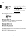
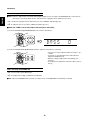
9. A product and cart combination should be
moved with care. Quick stops, excessive
force, and uneven surfaces may cause the
product and cart combination to overturn.
10. Ventilation - Slots and openings in the
cabinet are provided for ventilation and to
ensure reliable operation of the product PORTABLE CART WARNING
and to protect it from overheating, and
these openings must not be blocked or covered. The openings
should never be blocked by placing the product on a bed, sofa, rug,
or other similar surface. This product should not be placed in a
built-in installation such as a bookcase or rack unless proper
ventilation is provided or the manufacturer’s instructions have been
adhered to.
11. Power Sources - This product should be operated only from the
type of power source indicated on the marking label. If you are not
sure of the type of power supply to your home, consult your product
dealer or local power company. For products intended to operate
from battery power, or other sources, refer to the operating
instructions.
12. Grounding or Polarization - This product may be equipped with a
polarized alternating-current line plug (a plug having one blade
wider than the other). This plug will fit into the power outlet only one
way. This is a safety feature. If you are unable to insert the plug
fully into the outlet, try reversing the plug. If the plug should still fail
to fit, contact your electrician to replae your obsolete outlet. Do not
defeat the safety purpose of the polarized plug.
Alternate Warnings - This product is equipped with a three-wire
grounding-type plug, a plug having a third(grounding) pin. This plug
will only fit into a grounding-type power outlet. this is a safety
feature. If you are unable to insert the plug into the outlet, contact
your electrician to replace your obsolete outlet. Do not defeat the
safety purpose of the grounding-type plug.
13. Power-Cord Protection - Power-supply cords should be routed so
that they are not likely to be walked on or pinched by items placed
upon or against them, paying particular attention to cords at plugs,
convenience receptacles, and the point where they exit from the
product.
14. Outdoor Antenna Grounding - If an outside antenna or cable
system is connected to the product, be sure the antenna or cable
system is grounded so as to provide some protection against
voltage surges and built-up static charges. Article 810 of the
National Electrical Code, ANSI/NFPA 70, provides information with
regard to proper grounding of the mast and supporting structure,
grounding of the lead-in wire to an antenna discharge unit, size of
grounding conductors, location of antenna-discharge unit,
connection to grounding electrodes, and requirements for the
grounding electrode. See Figure 1.
15. Lightning - For added protection for this product during a lightning
storm, or when it is left unattended and unused for long periods of
time, unplug it from the wall outlet and disconnect the antenna or
cable system. This will prevent damage to the product due to
lightning and power-line surges.
16. Power Lines - An outside antenna system should not be located in
the vicinity of overhead power lines or other electric light or power
circuits, or where it can fall into such power lines or circuits. When
installing an outside antenna system, extreme care should be taken
to keep from touching such power lines or circuits as contact with
them might be fatal.
17. Overloading - Do not overload wall outlets, extension cords, or
integral convenience receptacles as this can result in a risk of fire
or electric shock.
18. Object and Liquid Entry - Never push objects of any kind into this
product through openings as they may touch dangerous voltage
points or short-out parts that could result in a fire or electric shock.
Never spill liquid of any kind on the product.
19. Servicing - Do not attempt to service this product yourself as
opening or removing covers may expose you to dangerous voltage
or other hazards. Refer all servicing to qualified service personnel.
20. Damage Requiring Service - Unplug this product form the wall
outlet and refer servicing to qualified service personnel under the
following conditions:
a) When the power-supply cord or plug is damaged,
b) If liquid has been spilled, or objects have fallen into the
product,
c) If the product has been exposed to rain or water,
d) If the product does not operate normally by following the
operating instructions. Adjust only those controls that are
covered by the operating instructions as an improper
adjustment of other controls may result in damage and will
often require extensive work by a qualified technician to
restore the product to its normal operation.
e) If the product has been dropped or damaged in any way, and
f) When the product exhibits a distinct change in performance this indicates a need for service.
21. Replacement Parts - When replacement parts are required, be
sure the service technician has used replacement parts specified
by the manufacturer or have the same characteristics as the
original part. Unauthorized substitutions may result in fire, electric
shock, or other hazards.
22. Safety Check - Upon completion of any service or repairs to this
product, ask the service technician to perform safety checks to
determine that the product is in proper operating condition.
23. Wall or Ceiling Mounting - The product should be mounted to a
wall or ceiling only as recommended by the manufacturer.
24. Heat - The product should be situated away from heat sources
such as radiators, heat registers, stoves, or other products
(including amplifiers) that produce heat.
2
Introduction
This symbol is intended to alert the user to the presence of
uninsulated "dangerous voltage" within the product's
enclosure that may be of sufficient magnitude to constitute a
risk of electric shock to persons.
CAUTION
WARNING
: TO REDUCE THE RISK OF ELECTRIC SHOCK, DO
NOT REMOVE COVER (OR BACK). NO USERSERVICEABLE PARTS INSIDE. REFER SERVICING
TO QUALIFIED SERVICE PERSONNEL.
This symbol is intended to alert the user to the presence of
important operating and maintenance (servicing) instructions
in the literature accompanying the appliance.
: TO REDUCE THE RISK OF FIRE OR ELECTRIC SHOCK,
DO NOT EXPOSE THIS APPLIANCE TO RAIN OR MOISTURE.
Caution regarding installation
Note : For heat dispersal, do not install this unit in a confined space such as a bookcase or similar enclosure.
Do not block ventilation openings or stack other equipment on the top.
Note to CATV System Installer :
This reminder is provided to call the CATV system installer’s attention to Article 820-40 of the NEC that provides guidelines for proper
grounding and, in particular, specifies that the cable ground shall be connected to the grounding system of the building, as close to the point
of cable entry as practical.
FCC INFORMATION
This equipment has been tested and found to comply with the limits for a Class B digital device, pursuant to Part 15 of the FCC Rules. These
limits are designed to provide reasonable protection against harmful interference in a residential installation. This equipment generates, uses and
can radiate radio frequency energy and, if not installed and used in accordance with the instructions, may cause harmful interference to radio
communications. However, there is no guarantee that interference will not occur in a particular installation. If this equipment does cause harmful
interference to radio or television reception, which can be determined by turning the equipment off and on, the user is encouraged to try to correct
the interference by one or more of the following measures:
• Reorient or relocate the receiving antenna.
• Increase the separation between the equipment and receiver.
• Connect the equipment into an outlet on a circuit different from that to which the receiver is connected.
• Consult the dealer or an experienced radio/TV technician for help.
Caution : Any changes or modifications in construction of this device which are not expressly approved by the party responsible for compliance
could void the user’s authority to operate the equipment.
FOR YOUR SAFETY
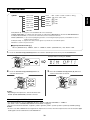
U.S.A
CANADA
120 V
Units shipped to the U.S.A and CANADA are designed for operation on 120 V AC only.
Safety precaution with use of a polarized AC plug.
However, some products may be supplied with a nonpolarized plug.
: To prevent electric shock, match wide blade of plug to wide slot, fully insert.
CAUTION
Pour éviter chocs électriques, introduire la lame la plus large de la fiche dans la borne
ATTENTION : correspondante
de la prise et pousser jusqu’ au fond.
CAUTION
• Leave a space around the unit for sufficient ventilation.
• Avoid installation in extremely hot or cold locations, or in an area that is exposed to direct sunlight or heating equipment.
• Keep the unit free from moisture, water, and dust.
• Do not let foreign objects in the unit.
• The ventilation should not be impeded by covering the ventilation openings with items, such as newspapers, table-cloths, curtains, etc.
• No naked flame sources, such as lighted candles, should be placed on the unit.
• Please be care the environmental aspects of battery disposal.
• The unit shall not be exposed to dripping or splashing for use.
• No objects filled with liquids, such as vases, shall be placed on the unit.
• Do not let insecticides, benzene, and thinner come in contact with the set.
• Never disassemble or modify the unit in any way.
■Notes on the AC power cord and the wall outlet.
• The unit is not disconnected from the AC power source(mains) as long as it is connected to the wall outlet, even if the unit has been turned off.
• When disconnecting the power cord from the wall outlet, always pull the plug, not the power cord.
• Disconnect the plug from the wall outlet when not using the unit for long periods of time.
• The wall outlet shall be installed near the unit and shall be easily accessible.
3
ENGLISH
READ THIS BEFORE OPERATING YOUR UNIT
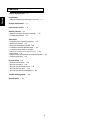
CONTENTS
ENGLISH
SAFETY INSTRUCTIONS
| 2
Introduction
• READ THIS BEFORE OPERATING YOUR UNIT
| 3
System Connections | 5
Front Panel Controls | 11
Remote Controls | 13
• REMOTE CONTROL OPERATION RANGE
• LOADING BATTERIES | 14
| 14
Operations
• LISTENING TO A PROGRAM SOURCE | 15
• SURROUND SOUND | 18
• ENJOYING SURROUND SOUND | 20
• LISTENING TO RADIO BROADCASTS | 26
• LISTENING TO XM SATELLITE RADIO
(XM Satellite Radio (only for North America)) | 28
• RECORDING | 31
• DIGITAL AUDIO RECORDING WITH MD RECORDER
• OTHER FUNCTIONS | 33
| 32
System Setup | 34
• SETTING THE SYSTEM | 37
• SETTING THE INPUT | 39
• SETTING THE SPEAKER SETUP | 41
• SETTING THE CH LEVEL | 48
• SETTING THE SOUND PARAMETER | 50
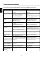
Troubleshooting Guide | 54
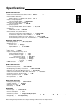
Specifications | 55
4
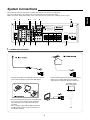
System Connections
VIDEO 2
PR/CR
PB/CB
Y
PR/CR
PB/CB
Y
PR/CR
PB/CB
Y
R
L
R
AUDIO
Manufactured under license from Digital
Theater Systems, Inc. U.S. Pat. No's.
5,451,942; 5,956,674; 5,974,380; 5,978,762; 6,487,535 and other
U.S. and world-wide patents issued and pending.
"DTS", "DTS-ES", "DTS 96/24" and "Neo:6" are trademarks of
Digital Theater Systems, Inc. Copyright 1996, 2003-2005 Digital
Theater Systems, Inc. All Rights Reserved.
AC INPUT
120V~60Hz
3.8A
MODEL NO.
RD-7502
AUDIO/ VIDEO RECEIVER
SN.
MADE IN CHINA
DESIGNED IN USA
SPEAKERS
AC OUTLET
SURROUND
(6 )
CENTER
(6 )
SURROUND BACK
(6 )
VIDEO 2
FRONT
(6 )
This device complies with Part 15 of the FCC rules.
Operation is subject to the following two conditions:
(1)This device may not cause harmful interference,and
(2)This device must accept any interference received,
including interference that may cause undesired operation.
VIDEO 1
VIDEO 1
CD
OPT OUT
AM
LOOP
DIGITAL
Manufactured under license from Dolby Laboratories.
"Dolby", "Pro Logic", and the double-D symbol are
trademarks of Dolby Laboratories.
MONITOR OUT
VIDEO
TAPE OUT
TAPE
VIDEO 1 OUT
VIDEO 1
VIDEO 1 OUT
VIDEO 2
CENTER
COAX 1
OPT 2
FRONT
GND
OPT 1
ANTENNA
FM
75
SURROUND SUBWOOFER
COAX 2
SUR.BACK
EXTERNAL IN
XM
MONITOR OUT
MONITOR OUT
SUBWOOFER
PRE OUT DIGI-LINK
ENGLISH
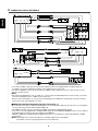
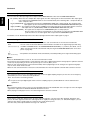
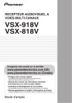
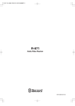
• Do not plug the AC input cord into the wall AC outlet until all connections are completed.
• Be sure to observe the color coding when connecting audio, video and speaker cords.
• Make connections firmly and correctly. If not, it can cause loss of sound, noise or damage to the receiver.
R
L
S-VIDEO
COMPONENT VIDEO
L
R
L
R
L
120V~60Hz
SWITCHED
TOTAL 120W(1A) MAX.
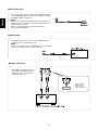
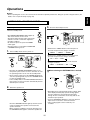
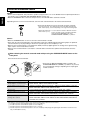
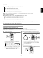
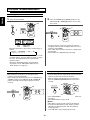
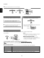
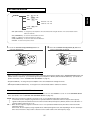
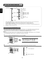
1. CONNECTING ANTENNAS
• Change the position of the FM indoor antenna until you
get the best reception of your favorite FM stations.
• Place the AM loop antenna as far as possible from
the receiver, TV set, speaker cords and the AC
input cord and set it to a direction for the best
reception.
• If the reception is poor with the AM loop antenna,
an AM outdoor antenna can be used in place of
the AM loop antenna.
5
• A 75Ω outdoor FM antenna may be used to further
improve the reception. Disconnect the indoor
antenna before replacing it with the outdoor one.
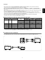
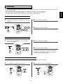
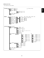
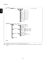
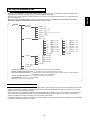
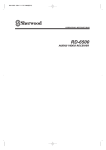
2. CONNECTING VIDEO COMPONENTS
HDMI OUT
COMPONENT
OUT
Y CB CR
AUDIO
OUT
R
L
AUDIO
IN
R
L
VIDEO 1 OUT
VIDEO 2
PR/CR
PB/CB
Y
PR/CR
PB/CB
Y
PR/CR
PB/CB
Y
VIDEO 2
TAPE
VIDEO 1
VIDEO 2
VIDEO 1
R
VIDEO 1
VIDEO 1 OUT
MONITOR OUT
VIDEO
S-VIDEO
OUT IN
L
AUDIO
S-VIDEO
COMPONENT VIDEO
OUT HDMI
VIDEO 1
VIDEO 2
PR/CR
PB/CB
Y
PR/CR
PB/CB
Y
AUDIO
OUT
L
R
MONITOR OUT
VIDEO
OUT (COMPOSITE)
VIDEO
COMPONENT
S-VIDEO
OUT
OUT
Y CB CR
VIDEO 2
VIDEO 2
HDMI
IN
(COMPOSITE)
VIDEO
IN
MONITOR OUT
MONITOR OUT
S-VIDEO
IN
VIDEO
COMPONENT
IN
Y CB CR
VIDEO 2
PR/CR
PB/CB
Y
MONITOR OUT
ENGLISH
(COMPOSITE) OUT
VIDEO IN
• The jacks of VIDEO 1 may also be connected to a DVD recorder or other digital video recording component.
For details, refer to the operating instructions of the component to be connected.
• The jacks of VIDEO 2 can also be connected to an additional video component such as a cable TV tuner, an LD
player or satellite system.
Note :
• When Sherwood DVD player such as V-768, etc. is connected to the DIGI-LINK jack for system control, you should
connect the DVD player to the " VIDEO 2" jacks of this unit.
Because, if the PLAY button, etc. is pressed on the DVD player, the VIDEO 2 is automatically selected as an input
source on this unit. Then playback, etc. starts.
HDMI(High Definition Multimedia Interface) connection : (*)
• You can connect the source component (DVD player, etc.) to the display component (TV, projector, etc.) through this
receiver with using a commercially available HDMI cord.
• The HDMI connection can carry uncompressed digital video signals and digital audio signals.
• This receiver can output digital video and digital audio signals from the MONITOR HDMI OUT of this receiver without
passing through any circuits as they were input into the HDMI IN.
• HDMI, the HDMI logo and High-Definition Multimedia Interface are trademarks or registered trademarks of HDMI
licensing LLC.
Note: Depending on the connected component, unreliable signal transfer may happen.
(For details, refer to the operating instruction of your component.)
6
• There are three types of video jacks(COMPONENT, S-VIDEO, (composite) VIDEO) for connecting video components.
Connect them to the corresponding video jacks according to their capability.
• For your reference, the excellence in picture quality is as follows : "COMPONENT” > "S-VIDEO” > "(composite) VIDEO”.
• When making COMPONENT VIDEO connections, connect "Y" to "Y", "PB/CB" to "CB" (or "B-Y", "PB") and "PR/CR" to "CR" (or
"R-Y", "PR" ).
• When recording video program sources through VIDEO 1 OUT jacks, you must use the same type of video jacks that you did
connect to video playback components such as DVD player, LD player, etc.
• This unit is equipped with a function that up-converts composite video or S-Video signals to component video signals or
down-converts S-Video signals to composite video signals and outputs them from the MONITOR OUTs. Because of this, you
need not connect all the types of MONITOR OUT jacks to the MONITOR TV.
• After connecting the video components, you should set the video mode correctly, referring to the following table.
(For details, refer to "When selecting the VIDEO MODE" on page 40.)
Relationship between the video input signal and the video output signal
Video input signals
COMPONENT
S-VIDEO
Video Mode
(composite) VIDEO
COMPONENT
S-VIDEO
(composite) VIDEO
“AT”(Auto)
Component
S-Video
Composite video
“CPN”(Component)*1
Component
×
×
“SVD”(S-Video)*2
S-Video
S-Video
S-Video
“CPS”(Composite)*2
Composite video
Composite video
Composite video
“AT”(Auto)
Component
S-Video
S-Video
“AT”(Auto)
Component
Composite video
Composite video
“AT”(Auto)
Component
×
×
“AT”(Auto)
S-Video
S-Video
Composite video
×
×
×
×
×
×
×
×
MONITOR OUTs
Setting
×
“AT”(Auto)
S-Video
S-Video
“AT”(Auto)
Composite video
Composite video
S-Video
Composite video
*1 : Component video signal can be output from the MONITOR COMPONENT OUT jacks only.
*2 : The video signal set in the VIDEO MODE menu can be output from all the types of MONITOR OUT jacks.
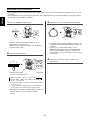
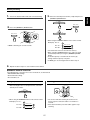
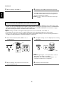
3. CONNECTING AUDIO COMPONENTS
• The TAPE IN/OUT jacks can be connected to audio recording equipment such as a tape deck, an MD recorder, etc.
TAPE
L
R
L
R
CD
CD player
AUDIO
OUT
L
R
7
Tape deck,
MD recorder, etc.
AUDIO
IN
AUDIO
OUT
ENGLISH
Continued
ENGLISH
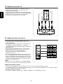
4. CONNECTING EXTERNAL INS
• Use these jacks to connect the corresponding outputs of a
DVD player or external decoder, etc. that has 6, 7 or 8
channel analog audio outputs
• In case of 6 or 7 channel outputs, do not connect both of the
SURROUND BACK L and R inputs or the SURROUND BACK
R input of this unit. (For details, refer to the operating
instructions of the component to be connected.)
5. CONNECTING DIGITAL INS AND OUT
• The OPTICAL and the COAXIAL DIGITAL OUTs of the
components that are connected to this unit can be connected
to these DIGITAL INs.
• A digital input should be connected to the components such
as a CD player, LD player, DVD player, etc. capable of
outputting DTS Digital Surround, Dolby Digital or PCM format
digital signals, etc.
• If the component with OPTICAL IN jack is connected to the
OPTICAL OUT jack of this unit, you can record the high
quality sound of CDs, etc. without degradation.
• For details, refer to the operating instructions of the
component connected.
• When making the COAXIAL DIGITAL connection, be sure to
use a 75 Ω COAXIAL cord, not a conventional AUDIO cord.
• All of the commercially available optical fiber cords cannot be
used for the equipment. If there is an optical fiber cord which
cannot be connected to your equipment, consult your dealer
or nearest service organization.
Note :
• Be sure to make either a OPTICAL or a COAXIAL DIGITAL
connection on each component. (You don’t need to do both.)
Digital input default settings
• If you connect the DIGITAL INs to your components, it is easier to do so following the default settings.
• If your DIGITAL connections are different from default settings, your should assign the DIGITAL INs you used with the "When
selecting the DIGITAL IN" procedure on page 39.
• The default settings are as follows :
OPTICAL IN 1 : VIDEO 1, OPTICAL IN 2 : VIDEO 2, COAXIAL IN 1 : CD, COAXIAL IN 2 : AUX.
8
6. CONNECTING SUBWOOFER PRE OUT
ENGLISH
• To emphasize the deep bass sounds, connect a powered
subwoofer.
7. CONNECTING DIGI-LINK
• Connect this jack to the DIGI LINK jack of the external
Sherwood component that uses the DIGI LINK II or III remote
control system.
Note :
• The DIGI LINK operation may not work on some Sherwood
components.
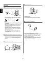
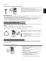
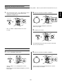
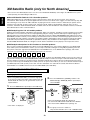
8. CONNECTING XM (only for North America)
• Connect the XM terminal to the XM Mini-Tuner system (sold
separately).
• Position the XM Mini-Tuner system near a south-facing
window to receive the best signal.
When making connections, also refer to the operating
instructions of the XM Mini-Tuner system.
• For the best reception, check the signal strength of the XM radio
signal with using signal strength display mode, then adjust the
position of the XM Mini-Tuner system until “GOOD” is displayed.
(For details, refer to “Displaying XM information” on page 30.)
• To listen to XM Satellite Radio, refer to “XM Satellite Radio
(only for North America)” on page 28.
XM Mini-Tuner system
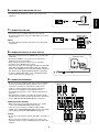
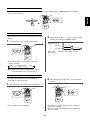
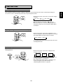
9. CONNECTING SPEAKERS
• Be sure to connect speakers firmly and correctly according to
the channel (left and right) and the polarity (+ and -). If the
connections are faulty, no sound will be heard from the
speakers, and if the polarity of the speaker connection is
incorrect, the sound will be unnatural and lack bass.
• For installing the speakers, refer to "Speaker placement" on
page 10.
• After installing the speakers, first adjust the speaker settings
according to your environment and speaker layout. (For details,
refer to "SETTING THE SPEAKER SETUP" on page 41.)
Surround back speakers
• When using only one surround back speaker, you should
connect it to SURROUND BACK LEFT channel.
In this case, you can connect a subwoofer without built-in
amplifier to the SURROUND BACK RIGHT channel. (For details,
refer to “When selecting the AMP ASSIGN” on page 37.)
Caution :
• Be sure to use the speakers with the impedance of 6 ohms or
above.
• Do not let the bare speaker wires touch each other or any
metal part of this unit. This could damage this unit and/or the
speakers.
9
R
L
R
L
R
L
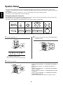
10. SWITCHED AC OUTLETS
ENGLISH
• These outlets are switched on(power-on mode) and
off(standby mode) according to power control as
follows(Maximum total capacity is 120 W (1 A)).
Standby mode - Switched AC outlet off
Power-on mode - Switched AC outlet on
11. AC INPUT CORD
• Plug this cord into a wall AC outlet.
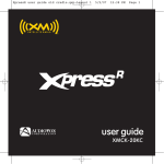
Speaker placement
Ideal speaker placement varies depending on the size of your
room and the wall coverings, etc. The typical example of
speaker placement and recommendations are as follows :
■Front left and right speakers and center speaker
• Place the front speakers with their front surfaces as flush with
TV or monitor screen as possible.
• Place the center speaker between the front left and right
speakers and no further from the listening position than the
front speakers.
• Place each speaker so that sound is aimed at the location of
the listener’s ears when at the main listening position.
■Surround left and right speakers
• Place the surround speakers approximately 1 meter (40
inches) above the ear level of a seated listener on the direct
left and right of them or slightly behind.
■Surround back left and right speakers
• Place the surround back speakers at the back facing the front
at a narrower distance than front speakers.
• When using a single surround back speaker, place it at the
rear center facing the front at a slightly higher position (0 to
20 cm) than the surround speakers.
• We recommend installing the surround back speaker(s) at a
slightly downward facing angle. This effectively prevents the
surround back channel signals from reflecting off the TV or
screen at the front center, resulting in interference and
making the sense of movement from the front to the back
less sharp.
■Subwoofer
• The subwoofer reproduces powerful deep bass sounds.
Place a subwoofer anywhere in the front as desired.
Notes :
• When using a conventional TV, to avoid interference with the
TV picture, use only magnetically shielded front left and right
and center speakers.
• To obtain the best surround effects, the speakers except the
subwoofer should be full range speakers.
10
1. TV or screen
7. Surround right speaker
2. Front left speaker
8. Surround back left speaker
3. Subwoofer
9. Surround back right speaker
4. Center speaker
10. Surround center speaker
5. Front right speaker
11. Listening position
6. Surround left speaker
ENGLISH
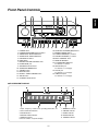
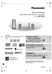
Front Panel Controls
AUDIO/VIDEO RECEIVER
RD-7502
XM
VIDEO 3
DISPLAY
D/A MODE
SETUP
CH. LEVEL
CONTROL
1. POWER switch
2. POWER ON/STANDBY button/indicator
3. VIDEO INPUT SELECTOR button
4. AUDIO INPUT SELECTOR button
5. EXTERNAL IN button
6. BAND button
7. MASTER VOLUME CONTROL knob
8. HEADPHONE jack
9. SPEAKER button/indicator
10. SURROUND MODE button
11. STEREO button
12. DISPLAY button
13. DIGITAL / ANALOG MODE button
14. SETUP button
15. CHANNEL LEVEL button
MEMO/ENTER
TUNE
PRESET
16. CONTROL UP/DOWN(▲/▼) buttons
17. MEMORY/ENTER button
18. TUNING UP/DOWN(+/-) buttons
19. PRESET UP/DOWN(+/-) buttons
20. MULTI CONTROL knob
21. REMOTE SENSOR
22. FLUORESCENT DISPLAY
For details, see below.
23. SETUP MIC jack
For details, see next page.
24. AUX IN jack
For details, see next page.
25. VIDEO 3 IN jacks
For details, see next page.
FLUORESCENT DISPLAY
1. Input, frequency, volume level, operating information, etc.
2. Surround mode indicators
3. AUTO indicator
4. DIGITAL INPUT indicator
5. DIRECT indicator
6. Preset number, sleep time display
11
7. MEMORY indicator
8. PRESET indicator
9. SLEEP indicator
10. TUNED indicator
11. STEREO indicator
ENGLISH
SETUP MIC JACK
• To use Auto Setup function, connect the supplied microphone
to the SETUP MIC jack.(For details, refer to "When selecting
the AUTO SETUP" on page 41.)
Notes:
• Because the microphone for Auto Setup is designed for use
with this receiver, do not use a microphone other than the one
supplied with this receiver.
• After you have completed the auto setup procedure,
disconnect the microphone.
AUX IN JACK
• The AUX IN jack can be connected to an additional audio
component such as an MP3 player, etc.
Note:
• When connecting this jack to an MP3 player, etc., you should
use the stereo mini cord, not a mono mini cord.
VIDEO 3 IN JACKS
• The VIDEO 3 IN jacks may be also
connected to an additional video
component such as a camcorder,
video game player, etc.
When not using the
VIDEO 3 IN jacks,
cover these jacks
with the supplied cap.
12
STANDBY
POWER ON
2
3
5
6
1
SLEEP
NUMERIC (1~0) buttons
4
8
7
ENGLISH
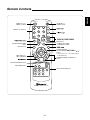
Remote Controls
DIMMER
9
MUTE
VOLUME
P.SCAN
0
D/A MODE CH.LEVEL
DIGITAL/ANALOG MODE
button
DISPLAY
MUTE button
SETUP
DISPLAY button
ENTER
SEL
SEL
TE
SOUND PARAMETER button
U
N
ARCH MODE
O
SE
ER
D
ST
ST
EO
R
SU
SOUND
TONE PARAMETER
R
CUSOR CONTROL
ENTER</SEARCH MODE, SELECT / >
buttons
• The functions in "< >" are regional option
for North America.
SURROUND MODE UP/DOWN(>/<)
buttons
EXT.IN
TONE MODE button
TAPE
VIDEO 1
VIDEO 2
VIDEO 3
INPUT SELECTOR buttons
FM/AM/XM
CD
AUX
REMOTE CONTROL RC-110
13
ENGLISH
REMOTE CONTROL OPERATION RANGE
AUDIO/VIDEO RECEIVER
RD-7502
XM
VIDEO 3
DISPLAY
D/A MODE
STANDBY
POWER ON
2
3
5
6
1
4
8
7
SETUP
SLEEP
DIMMER
9
CH. LEVEL
CONTROL
MEMO/ENTER
TUNE
PRESET
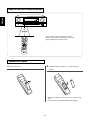
• Use the remote control unit within a range of
about 7 meters (23 feet) and angles of up to 30
degrees aiming at the remote sensor.
MUTE
VOLUME
P.SCAN
0
D/A MODE CH.LEVEL
DISPLAY
SETUP
ENTER
SEL
SEL
TE
SEA
ER
EO
R C H MOD
OU
ND
ST
ST
E
SU
SOUND
TONE PARAMETER
RR
EXT.IN
TAPE
VIDEO 1
VIDEO 2
FM/AM/XM
CD
AUX
VIDEO 3
REMOTE CONTROL RC-110
LOADING BATTERIES
1. Remove the cover.
2. Load two batteries("AAA" size, 1.5V) matching the
polarity.
• Remove the batteries when they are not used for a long
time.
• Do not use the rechargeable batteries(Ni-Cd type).
14
Operations
ENGLISH
Notes:
• Before operating this receiver, first set this unit as desired for optimum performance, doing the system setup procedures. (For
details, refer to “System Setup” on page 34)
LISTENING TO A PROGRAM SOURCE
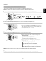
3. Select the desired input source.
Before operation
• Enter the standby mode.
D/A MODE CH.LEVEL
DISPLAY
SETUP
ENTER
SEL
SEL
TE
ST
STANDBY
POWER ON
2
3
5
6
1
4
7
8
TAPE
VIDEO 1
VIDEO 2
FM/AM/XM
CD
AUX
VIDEO 3
EXT.IN
TAPE
VIDEO 1
VIDEO 2
FM/AM/XM
CD
AUX
VIDEO 3
SLEEP
DIMMER
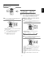
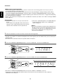
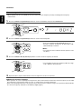
• Each time the BAND button is pressed, the band
changes as follows;
→ FM ST → FM MONO → AM → XM
9
VOLUME
SETUP
ENTER
RR
• Each time the "AUDIO" button on the front panel is
pressed, the input source changes as follows:
→ CD → AUX → TAPE
STANDBY
0
SEL
SU
• Each time the "VIDEO" button on the front panel is
pressed, the input source changes as follows:
→ VIDEO 1 → VIDEO 2 → VIDEO 3
D/A MODE CH.LEVEL
DISPLAY
E
REMOTE CONTROL RC-110
MUTE
P.SCAN
R C H MOD
SOUND
TONE PARAMETER
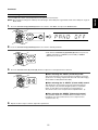
1. In the standby mode, turn the power on.
POWER ON
SEA
ER
EO
OU
ND
ST
• The POWER ON/STANDBY button lights up .
This means that the receiver is not
disconnected from the AC mains and a small
amount of current is retained to support the
operation readiness.
• To switch the power off, push the POWER
switch again.
• Then the power is cut off and the POWER ON
/ STANDBY button goes off.
SEL
TE
ST
• Each time the POWER ON/STANDBY button on the
front panel is pressed, the receiver is turned on to enter
the operating mode or off to enter the standby mode.
• On the remote control, press the POWER ON button to
enter the operating mode or press the STANDBY button
to enter the standby mode.
• In the standby mode, if the INPUT SELECTOR button is
pressed, the receiver is turned on automatically and the
desired input is selected.
When selecting the EXTERNAL IN as desired,
ENTER
SEL
SEL
TE
SEA
ER
EO
R C H MOD
E
SU
SOUND
TONE PARAMETER
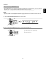
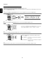
2. Switch the speakers on.
OU
ND
ST
ST
RR
EXT.IN
EXT.IN
TAPE
VIDEO 1
VIDEO 2
FM/AM/XM
CD
AUX
VIDEO 3
REMOTE CONTROL RC-110
• Depending on the surround back speaker setting, "EXT
IN" is displayed and 8(/7/6) separate analog signals
from the component connected to this input pass
through the tone and volume circuits only and can be
heard from your speakers.
• Press the EXTERNAL IN button or select the desired
input source to cancel the external in function.
• These analog signals can be heard only, not
recorded.
• Then the SPEAKER indicator lights up and the sound
can be heard from the speakers connected to the
speaker terminals.
• When using the headphone for private listening, press
the SPEAKER button again to switch the speakers off.
15
7. To mute the sound.
When CD, AUX, VIDEO 1~2 is selected as an
input source
STANDBY
POWER ON
2
3
5
6
1
4
7
2
3
1
D/A MODE
6
5
4
8
MUTE
9
MUTE
SLEEP
VOLUME
P.SCAN
0
D/A MODE CH.LEVEL
DIMMER
DISPLAY
8
7
SLEEP
DIMMER
STANDBY
POWER ON
D/A MODE
SETUP
9
MUTE
VOLUME
P.SCAN
0
D/A MODE CH.LEVEL
SEL
SETUP
ENTER
SEL
TE
DISPLAY
D
ST
ENTER
SEL
SEL
TE
SEA
ER
EO
R C H MOD
E
OU
ND
ST
ST
R
UR
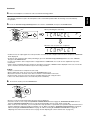
• "MUTE" will flicker.
• To resume the previous sound level, press it again.
• Each time this button is pressed, the corresponding
input is selected as follows:
→ A(nalog) → o(ptical) 1 → o(ptical) 2
c(oaxial) 2 ← c(oaxial) 1 ←
8. To listen with the headphones.
Notes :
• When TUNER, TAPE, EXTERNAL IN or VIDEO 3 is
selected as an input source, the analog input is selected
automatically.
• When the selected digital input is not connected, the
"DIGITAL" indicator flickers and the analog input is
automatically selected.
• The selected digital or analog input is automatically
assigned to the corresponding input source on the
INPUT setup menu. (For details, refer to "SETTING
THE INPUT" on page 39.)
• The sound from the component connected to the
selected digital input can be heard regardless of the
selected input source.
• Ensure that the SPEAKER button is set to off.
• Depending on the signal format which is being input, you
can listen in different Dolby Headphone modes, stereo
mode, etc. (For details, refer to "Listening in a Dolby
Headphone mode" on page 21).
• When the EXTERNAL IN is selected as an input source,
only front left and front right channel signals can be
reproduced through the headphones.
5. Operate the selected component for playback.
• When playing back the program sources with surround
sound, refer to "ENJOYING SURROUND SOUND" on
page 20.
6. Adjust the (overall) volume.
STANDBY
POWER ON
2
3
5
6
1
4
8
7
SLEEP
DIMMER
VOLUME
9
MUTE
VOLUME
P.SCAN
0
D/A MODE CH.LEVEL
DISPLAY
SETUP
ENTER
SEL
SEL
TE
ST
ST
SEA
ER
EO
R C H MOD
E
OU
ND
ENGLISH
4. Select the digital or analog input connected as desired.
RR
16
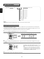
Adjusting the tone (bass and treble)
9. Enter the tone mode.
SETUP
ENTER
SEL
ENGLISH
DISPLAY
SEL
TE
SEA
ER
EO
R C H MOD
OU
ND
ST
ST
E
SU
TONE
SOUND
TONE PARAMETER
RR
EXT.IN
TAPE
VIDEO 1
VIDEO 2
FM/AM/XM
CD
AUX
VIDEO 3
REMOTE CONTROL RC-110
• The tone mode is displayed for several seconds.
Note : When the digital signals from DTS, Dolby Digital program
sources are input or the EXTERNAL IN is selected can
listen to a program source without the tone effect.
When the “TONE” is set to ON to adjust the
tone (bass and treble).
10. Press the CURSOR LEFT(◀)/RIGHT(▶) buttons to
select the desired tone mode.
8
7
11. Press the CURSOR UP(▲)/DOWN(▼) buttons to
9
MUTE
VOLUME
P.SCAN
0
D/A MODE CH.LEVEL
DISPLAY
select the desired tone.
SETUP
ENTER
SEL
8
7
SEL
9
MUTE
VOLUME
P.SCAN
TE
0
ST
SEA
ER
EO
R C H MOD
E
SU
SOUND
TONE PARAMETER
D/A MODE CH.LEVEL
OU
ND
ST
RR
DISPLAY
SETUP
EXT.IN
VIDEO 1
VIDEO 2
FM/AM/XM
CD
AUX
ENTER
SEL
VIDEO 3
SEL
TE
TAPE
SEA
ER
EO
R C H MOD
OU
ND
ST
ST
E
SU
SOUND
TONE PARAMETER
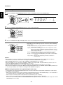
• Each time these buttons are pressed, the tone mode is
selected as follows:
OFF : To listen to a program source without the tone
effect. (“DIRECT” indicator lights up.)
RR
EXT.IN
TAPE
VIDEO 1
VIDEO 2
FM/AM/XM
CD
AUX
VIDEO 3
• Each time these buttons are pressed, the tone is
selected as follows:
ON : To adjust the tone for your taste.
(“DIRECT” indicator goes off.)
BASS
TRBL(treble)
TONE ON
12. Press the CURSOR LEFT(◀)/RIGHT(▶) buttons to
adjust the selected tone as desired.
8
7
9
MUTE
VOLUME
P.SCAN
0
D/A MODE CH.LEVEL
DISPLAY
SETUP
ENTER
SEL
SEL
TE
SEA
ER
EO
R C H MOD
OU
ND
ST
ST
E
S
SOUND
TONE PARAMETER
R
UR
EXT.IN
TAPE
VIDEO 1
VIDEO 2
FM/AM/XM
CD
AUX
VIDEO 3
• The tone level can be adjusted within the range of -10 ~
+10 dB.
• In general, we recommend the bass and treble to be
adjusted to 0 dB (flat level).
• Extreme settings at high volume may damage your
speakers.
• To complete tone adjustment, repeat the above steps 11
and 12.
• If the tone display disappears, start from the step 9
again.
17
SURROUND SOUND
ENGLISH
• This receiver incorporates a sophisticated Digital Signal Processor that allows you to create optimum sound quality and sound
atmosphere in your personal Home Theater.
Surround modes
• DTS Neo : 6 Cinema
This mode is optimum for playing movies. Decoding is
performed with emphasis on separation performance to
achieve the same atmosphere with 2-channel sources as
with 6.1-channel sources.
DTS Digital Surround
DTS Digital Surround(also called simply DTS) is a multichannel digital signal format which can handle higher data
rates. Discs bearing the "
" include the recording of
up to 5.1 channels of digital signals, which can be generally
thought to provide better sound quality due to the lower audio
compression required.
It also provides wide dynamic range and separation, resulting
in magnificent sound.
DTS - ES Extended Surround™ (
)
This is a new multi channel digital signal format which greatly
improves the 360- degree surround impression and space
expression thanks to further expanded surround signals, offering
high compatibility with the conventional DTS format.
In addition to the 5.1 channels, DTS-ES Extended Surround also
offers the surround back (sometimes also referred to as
"surround center") channel for surround playback with a total of
6.1 channels. DTS-ES Extended Surround includes two signal
formats with different surround signal recording methods as
follows:
• DTS-ES™ Discrete 6.1
Because the signals for 6.1 channels (including the surround back
channel) are fully independent, it is possible to achieve a sense
that the acoustic image are moving about freely among the
background sounds surrounding the listener from 360 degrees.
Though maximum performance is achieved when sound tracks
recorded with this system are played using a DTS -ES decoder,
when played with a conventional DTS decoder, the surround back
channel signals are automatically downmixed to the surround left
and surround right channels so that none of the signal
components are lost.
• DTS - ES™ Matrix 6.1
With this format, the additional surround back channel signals
undergo matrix encoding and are input to the surround left and
surround right channels beforehand. During playback, they are
decoded to the surround left, surround right and surround back
channels.
Because the bit stream format is 100% compatible with
conventional DTS signals, the effect of the DTS-ES Matrix 6.1
format can be achieved even with DTS 5.1- channel signal
sources. Of course, it is possible to play DTS-ES Matrix 6.1 channel signal sources with a DTS 5.1 - channel decoder.
When DTS-ES Discrete 6.1 or Matrix 6.1 sources are decoded
with a DTS - ES decoder, the format is automatically detected
upon decoding and the optimum surround mode is selected.
However, some DTS - ES Matrix 6.1 sources may be detected
as DTS sources. In this case, the DTS - ES Matrix mode should
be selected manually to play these sources.
DTS Neo : 6™ surround
This mode applies conventional 2-channel signals such as digital
PCM or analog stereo signals to the high precision digital matrix
decoder used for DTS-ES Matrix 6.1 to achieve 6.1-channel
surround playback. DTS Neo : 6 surround includes two modes for
selecting the optimum decoding for the signal source.
18
• DTS Neo : 6 Music
This mode is suited mainly for playing music. The front left
and front right signals bypass the decoder and are played
directly so there is no loss of sound quality, and the effect of
the surround signals from the center, surround left, surround
right and surround back channels adds a natural sense of
expansion to the sound field.
DTS 96/24
Conventional surround formats used sampling frequencies
of 48 or 44.1 kHz, so 20 kHz was about the maximum
playback signal frequency. With DTS 96/24, the sampling
frequency is increased to 96 or 88.2 kHz to achieve a wide
frequency range of over 40 kHz. In addition, this format has
a resolution of 24 bits, resulting in the same frequency band
and dynamic range as 96kHz / 24 bit PCM signals.
As with conventional DTS surround, DTS 96/24 is
compatible with a maximum of 5.1 channels. DTS 96/24 is
fully compatible with the conventional DTS surround format,
so DTS 96/24 sources can be played using a conventional
DTS 5.1 channel decoder.
"DTS", "DTS-ES", "DTS 96/24" and "Neo:6" are trademarks
of Digital Theater Systems, Inc.
Dolby Digital
Dolby Digital is the multi- channel digital signal format
developed by Dolby Laboratories. Discs bearing the
"
" includes the recording of up to 5.1 channels of
digital signals, which can reproduce much better sound
quality, spatial expansion and dynamic range characteristics
than the previous Dolby Surround effect.
Dolby Digital EX
This mode creates the back (sometimes also referred to as
"surround center") signals from the surround left and right
signals in Dolby Digital 5.1 channel source using a matrix
decoder and provides 6.1 channel surround playback. For
the best results, this mode should be selected during
playback of sources(bearing the "
") recorded in
Dolby Digital EX.
With this additional channel, you can experience more
dynamic and realistic moving sound especially.
When Dolby Digital EX sources are decoded with a Dolby
Digital EX decoder, the format is automatically detected
upon decoding and the Dolby Digital EX mode is selected.
However, some Dolby Digital EX sources may be detected
as Dolby Digital sources. In this case, the Dolby Digital EX
mode should be selected manually to play these sources.
Dolby Pro Logic
• Dolby Pro Logic IIx Music
When listening to music, this mode allows you to further
enhance the sound quality by adding processing that
emphasizes the musical effects.
Dolby Pro Logic II surround
This mode applies conventional 2-channel signals such as
digital PCM or analog stereo signals as well as Dolby Surround
signals, etc. to surround processing to offer improvements over
conventional Dolby Pro Logic circuits.
Dolby Pro Logic II surround includes Dolby Pro Logic II Movie
and Dolby Pro Logic II Music like Dolby Pro Logic IIx surround.
Dolby Virtual Speaker
This mode creates a virtual surround sound field using as few
as two front speakers, allowing you to experience listening from
5.1 channel speakers.
This mode is effective not only for 5.1 channel sources but also
for stereo(2 channel) sources.
Dolby VIrtual Speaker includes two listening mode as follows:
Dolby Pro Logic is a specially encoded two channel surround
format which consists of four channels (front left, center, front
right and surround). Sources bearing the
"
" provide the theater-like surround sound.
The surround channel is monaural, but is played through
both surround speakers.
Dolby Headphone
The Dolby Headphone function simulates 5.1 channel
surround sound, which allows you to enjoy 5.1 channel
surround sound through 2 channel headphones, just like
listening from 5.1 channel speakers.
This mode is effective not only for 5.1 channel sources but
also for stereo(2 channel) sources.
Manufactured under license from Dolby Laboratories.
"Dolby", "Pro Logic" and the double-D symbol are
trademarks of Dolby Laboratories.
• The following modes apply conventional 2-channel signals
such as digital PCM or analog stereo signals to high
performance Digital Signal Processor to recreate sound
fields artificially. Select one of the 3 provided surround
modes according to the program source you want to play.
Theater
This mode provides the effect of being in a movie theater
when watching a movie.
Hall
This mode provides the ambience of a concert hall for
classical music sources such as orchestral, chamber music
or an instrumental solo.
• Dolby Virtual Speaker Reference
The width of the front sound image is defined by the actual
distance between front speakers.
Stadium
• Dolby Virtual Speaker Wide
The width of the front sound image seems to extend beyond
the front speakers.
This mode provides the expansive sound field to achieve the
true stadium effect when watching baseball or soccer games.
• When using the EXTERNAL INs to play back the sound from the additional multi-channel decoder for surround sound, you can
enjoy the corresponding surround sound, too.(For details, refer to the operating instructions of the component to be
connected.)
For your reference, the sound from each channel can be reproduced according to the surround modes as follows:
Modes
Channels
FRONT L/R
CENTER
SURROUND L/R
SURROUND BACK L/R
SUBWOOFER
—
DTS, DTS 96/24
DTS ES DISCRETE/MATRIX
—(*)
DTS NEO: 6 CINEMA/MUSIC
—
DOLBY DIGITAL
DOLBY DIGITAL EX
DOLBY PRO LOGIC IIx MOVIE/MUSIC
DOLBY PRO LOGIC II MOVIE/MUSIC
—
DOLBY PRO LOGIC
—
—(*)
DOLBY VIRTUAL SPEAKER
—
—(*)
—(*)
Other Surrounds
STEREO
—
—
—
—(*)
EXTERNAL IN
(*): Depending on the subwoofer setting, the sound from the subwoofer channel may be reproduced.
• Depending on the speaker settings and the number of the encoded channels, etc., the sound from the corresponding channels
cannot be reproduced.(For details, refer to "SETTING THE SPEAKER SETUP" on page 41.)
19
ENGLISH
Dolby Pro Logic IIx surround
Dolby Pro Logic IIx decodes all stereo (2 channel ) and 5.1
channel sources and extends to 7.1channel surround playback.
It delivers the most natural, full range and immersing 7.1
channel listening experience. Dolby Pro Logic IIx surround
includes two modes as follows :
• Dolby Pro Logic IIx Movie
When enjoying movies, this mode allows you to further
enhance the cinematic quality by adding processing that
emphasizes the sounds of the action special effects.
Notes:
• Before surround playback, first perform the speaker setup procedure, etc. on the SETUP menu for optimum performance.
(For details, refer to "SETTING THE SPEAKER SETUP" on page 41.)
• When the EXTERNAL IN is selected as an input source, the surround modes cannot be selected.
Depending on how to select a surround mode, select the auto surround mode or the manual surround mode.
• Each time this button is pressed, the mode changes as follows :
Auto surround mode : The optimum surround mode will be automatically
selected depending on the signal format being input.
("AUTO" indicator lights up)
Manual surround mode : You can select the desired of different surround
modes selectable for the signal being input with
using the MULTI CONTROL knob or the
SURROUND MODE UP/DOWN (>/<) buttons.
(“AUTO” indicator goes off)
Notes :
• When the SPEAKER button is set to off, the auto surround mode is invalid.
• Even when the auto surround mode is selected and the same type of digital signal format is being input, the optimum
surround mode may vary depending on whether the speaker type is set to "N”(None) or not.
• When the auto surround mode is selected and the PCM (2 channel) digital signal or the analog stereo signal is being
input, only the stereo mode will be selected.
• When the auto surround mode is selected, the surround modes other than the optimum surround mode cannot be
selected.
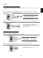
■When selecting the manual surround mode with pressing the SURROUND MODE button on the
front panel.
Select the desired surround mode.
D/A MODE CH.LEVEL
SETUP
DISPLAY
ENTER
SEL
SEL
TE
ST
SEA
ER
EO
R C H MOD
E
SU
SOUND
TONE PARAMETER
RR
EXT.IN
VIDEO 1
VIDEO 2
CD
AUX
VIDEO 3
O
TAPE
FM/AM/XM
U
N
D
ST
OU
ND
ENGLISH
ENJOYING SURROUND SOUND
SU
R
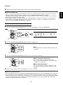
• Each time the MULTI CONTROL knob is rotated or the
SURROUND MODE UP / DOWN (>/<) buttons are pressed,
the surround mode changes depending on the input signal
format as follows :
R
REMOTE CONTROL RC-110
Signal format being input
Selectable surround mode
Dolby Digital EX6.1 channel sources,
(DOLBY D + PLIIx MOVIE), < DOLBY D + PLIIx MUSIC, DOLBY DIGITAL EX>,
Dolby Digital 5.1 channel sources
DOLBY DIGITAL, DOLBY VS REF, DOLBY VS WIDE
Dolby Digital 2 channel sources
<DOLBY PLIIx MOVIE, DOLBY PLIIx MUSIC>, [DOLBY PLII MOVIE, DOLBY PLII MUSIC],
DTS sources
corresponding DTS mode, DOLBY VS REF, DOLBY VS WIDE, {DTS + NEO:6}
DOLBY PRO LOGIC, DOLBY VS REF, DOLBY VS WIDE
96 kHz PCM (2channel) sources
<DOLBY PLIIx MOVIE, DOLBY PLIIx MUSIC>, [DOLBY PLII MOVIE, DOLBY PLII MUSIC],
DOLBY PRO LOGIC, NEO:6 CINEMA, NEO:6 MUSIC, THEATER, HALL, STADIUM
PCM (2channel) sources,
<DOLBY PLIIx MOVIE, DOLBY PLIIx MUSIC>, [DOLBY PLII MOVIE, DOLBY PLII MUSIC],
Analog stereo sources
DOLBY PRO LOGIC, DOLBY VS REF, DOLBY VS WIDE, NEO:6 CINEMA, NEO:6 MUSIC,
THEATER, HALL, STADIUM
• Depending on surround speaker setting, some surround modes can be selected or not as follows:
< >: Possible only when surround back speaker is not set to "N"(None).
[ ] : Possible only when surround back speaker is set to "N"(None).
( ): Possible only when surround back speaker is set to " 2c"(2ch).
{ }: Possible only when surround back speaker is not set to "N”(None) while playing the digital signals from DTS 5.1 channel sources
only(, not DTS 96/24 sources).
20
Continued
To cancel the surround mode for stereo operation
SETUP
ENTER
SEL
• Depending on the signal format which is being input, either the stereo
mode or the 2CH downmix mode is selected.
• To cancel either the stereo mode or the 2CH downmix mode, select
the surround mode with using the MULTI CONTROL knob on the front
panel or the SURROUND MODE UP/DOWN ( >/< ) buttons on the
remote control.
SEL
TE
ER
SEA
ER
EO
R C H MOD
E
SU
SOUND
TONE PARAMETER
EO
OU
ND
ST
ST
ST
RR
EXT.IN
TAPE
VIDEO 1
VIDEO 2
FM/AM/XM
CD
AUX
VIDEO 3
REMOTE CONTROL RC-110
2CH downmix mode
• This mode allows the multi-channel signals encoded in DTS or Dolby Digital format to be mixed down into 2 front channels and
to be reproduced through only two front speakers or through headphones.
• When the SPEAKER button is set to off to listen with headphones, if the STEREO button is pressed while playing the multichannel digital signals from DTS or Dolby Digital sources, it will enter the 2CH downmix mode automatically.
• To cancel the 2CH downmix mode, select the desired Dolby Headphone mode with using the MULTI CONTROL knob on the
front panel or the SURROUND MODE UP/DOWN ( >/< ) buttons on the remote control.
Listening in a Dolby Headphone mode
• The Dolby Headphone function simulates 5.1 channel surround sound, which allows you to enjoy 5.1 channel surround sound
through 2 channel headphones, just like listening from 5.1 channel speakers.
Notes :
• Only when the SPEAKER button is set to off, the Dolby Headphone mode can be selected.
• When playing the 96 kHz PCM(2 channel) digital signals, only the stereo mode can be selected.
• While listening with headphones, select the desired Dolby Headphone mode.
DISPLAY
SETUP
ENTER
SEL
• Each time the MULTI CONTROL knob is rotated or the SURROUND
MODE UP/DOWN ( >/< ) buttons are pressed, the mode changes as
follows :
SEL
TE
R C H MOD
E
SU
RR
EXT.IN
VIDEO 1
VIDEO 2
CD
AUX
VIDEO 3
O
TAPE
FM/AM/XM
U
N
D
SEA
ER
EO
OU
ND
ST
ST
SOUND
TONE PARAMETER
SU
R
R
REMOTE CONTROL RC-110
DH 1 : This simulates the soundfield as if you were in a relatively small room
with less reverberations.
DH 2 : This simulates the soundfield as if you were in a typical listening room
with moderate reverberations.
DH 3 : This simulates the soundfield as if you were in a large space like
theater.
When adjusting the sound parameters
• While playing digital signals from Dolby Digital or DTS program source or listening in a surround mode such as Dolby Pro
Logic II / Dolby Pro Logic IIx Music, Dolby Headphone, Dolby Virtual Speaker mode, you can adjust their parameters for
optimum surround effect.
1. Press the SOUND PARAMETER button.
DISPLAY
SETUP
ENTER
SEL
SEL
TE
SOUND
PARAMETER
SEA
ER
EO
R C H MOD
OU
ND
ST
ST
E
SU
SOUND
TONE PARAMETER
RR
EXT.IN
TAPE
VIDEO 1
VIDEO 2
FM/AM/XM
CD
AUX
VIDEO 3
REMOTE CONTROL RC-110
• Depending on the kind of digital input signal or/and the selected
surround mode, the corresponding parameter mode is displayed
for several seconds as follows:
* “NIGHT” (Night mode) :
Selectable only while playing digital signals from Dolby Digital or DTS
source.
* “PANO” (Panorama mode) :
Selectable only while listening in Dolby Pro Logic II/Dolby Pro Logic IIx
Music mode.
* “REF” or “WIDE” (Dolby VS Reference/Wide mode) :
Selectable only while listening in Dolby Virtual Speaker mode.
* “DH 1” (Dolby Headphone 1 mode) :
Selectable only while listening in Dolby Headphone mode.
• If the parameter mode disappears, press this button again.
21
ENGLISH
DISPLAY
Continued
8
7
9
MUTE
VOLUME
P.SCAN
0
D/A MODE CH.LEVEL
DISPLAY
SETUP
ENTER
SEL
SEA
ER
EO
R C H MOD
OU
ND
ST
ST
E
SU
SOUND
TONE PARAMETER
• Depending on the surround mode, each time these buttons are
pressed, the parameter mode changes as follows:
* When listening in Dolby Pro Logic II/Dolby Pro Logic IIx Music mode, you
can adjust the various surround parameters for optimum surround effect.
“PANO”
“C.WIDTH”
“DIMEN”
SEL
TE
RR
(Panorama mode)
(Center width control)
(Dimension control)
EXT.IN
TAPE
VIDEO 1
VIDEO 2
FM/AM/XM
CD
AUX
* When listening in Dolby Virtual Speaker mode, you can select the speaker
layout to be used actually for each Dolby Virtual Speaker mode.
REF
WIDE
VIDEO 3
(Dolby VS Reference mode)
(Dolby VS Wide mode)
* When listening in Dolby Headphone mode, you can select the desired
listening mode for each Dolby Headphone mode.
DH 1
DH 2
DH 3
(Dolby Headphone 1 mode)
3. Press the CURSOR LEFT(◀)/RIGHT(▶) buttons to adjust the selected parameter as desired.
8
7
9
MUTE
VOLUME
P.SCAN
0
D/A MODE CH.LEVEL
DISPLAY
SETUP
ENTER
SEL
SEL
TE
ST
ST
SEA
ER
EO
R C H MOD
OU
ND
ENGLISH
2. Press the CURSOR UP(▲)/DOWN(▼) buttons to select the desired parameter.
E
S
SOUND
TONE PARAMETER
R
UR
EXT.IN
TAPE
VIDEO 1
VIDEO 2
FM/AM/XM
CD
AUX
VIDEO 3
When selecting the “NIGHT” (Night mode)
This function compresses the dynamic range of previously specified parts of the Dolby Digital or DTS sound track (with
extremely high volume) to minimize the difference in volume between the specified and non specified parts.
This makes it easy to hear all of the sound track when watching movies at night at low levels.
The night mode can be set in 11 steps from 0.0 to 1.0 (default value : 0.0)
Note: In some Dolby Digital or DTS softwares, the night mode may not be valid.
[Dolby Pro Logic II/Dolby Pro Logic IIx Music Parameters]
When selecting the “PANO” (Panorama) mode
This mode extends the front stereo image to include the surround speakers for an exciting “wraparound” effect with side wall
imaging. Select “OFF” or “ON” (default value : OFF).
When selecting the “C.WIDTH” (Center width) control
This adjusts the center image so it may be heard only from the center speaker, only from the left/right speakers as a phantom
image, or from all three front speakers to varying degrees.
The control can be set it 8 steps from 0 to 7 (default value : 3).
When selecting the “DIMEN” (Dimension) control
This gradually adjusts the soundfield either towards the front or towards the rear. The control can be set in 7 steps from -3 to +3
(default value : 0).
[Dolby Virtual Speaker Parameters]
When selecting the “REF” (Dolby Virtual Speaker Reference) mode
2 SP : When using 2 front speakers only.
3 SP : When using 2 front and center speakers.
22
Continued
When selecting the “WIDE” (Dolby Virtual Speaker Wide) mode
2 SP : When using 2 front speakers only.
ENGLISH
3 SP : When using 2 front and center speakers
4 SP : When using 2 front and 2 surround speakers.
5 SP : When using 2 front, center and 2 surround speakers.
Note: When the speakers are set to “N” (None), the corresponding speaker layouts cannot be selected.
[Dolby Headphone Parameters]
When selecting the “DH 1”, “DH 2”, “DH 3” (Dolby Headphone 1,2,3) mode
MOVIE : This provides the surround effect suitable for movie sources.
MSC 1 : This provides the surround effect suitable for music sources.
MSC 2 : This provides less surround effect compared to Music 1 mode.
Note : You can select the listening mode only when playing analog stereo, PCM 2 channel or Dolby Digital 2 channel source.
4. Repeat the above steps 2 and 3 to adjust other parameters
Adjusting each channel level with test tone
• The volume level of each channel can be adjusted easily with the test tone function.
Note : When the SPEAKER button is set to off or it is in the stereo mode, etc., the test tone function does not work.
1. Enter the test tone mode.
2. At each channel, adjust the level as desired until the
sound level of each speaker is heard to be equally loud.
D/A MODE CH.LEVEL
DISPLAY
SETUP
4
ENTER
SEL
8
7
SEL
9
MUTE
VOLUME
P.SCAN
TE
SEA
ER
EO
R C H MOD
OU
ND
ST
0
ST
E
SU
TE
ST
SOUND
TONE PARAMETER
D/A MODE CH.LEVEL
RR
DISPLAY
SETUP
EXT.IN
VIDEO 1
VIDEO 2
CD
AUX
ENTER
SEL
VIDEO 3
SEL
TE
TAPE
FM/AM/XM
SEA
ER
EO
R C H MOD
OU
ND
ST
ST
E
S
SOUND
TONE PARAMETER
R
UR
EXT.IN
TAPE
VIDEO 1
VIDEO 2
FM/AM/XM
CD
AUX
VIDEO 3
REMOTE CONTROL RC-110
• The test tone will be heard from the speaker of each
channel for 2 seconds as follows:
→ FL → C → FR → SR
Center
Front Right
Surround Right
3. Cancel the test tone function.
SW ← SL ( ← SB) or ( ← BL ← BR) ←
Subwoofer
Surround Left
Surround Back Surr.Back Left Surr.Back Right
• When the speaker setting is "N” (None or No), the test
tone of the corresponding channel is not available.
• ( ) : Possible depending on whether the surround back
channel is set to "2c" (2ch) or "1c" (1ch).
DISPLAY
SETUP
ENTER
SEL
SEL
TE
ST
ST
SEA
ER
EO
R C H MOD
OU
ND
Front Left
• You can select the desired channel with pressing the
CONTROL UP(▲)/DOWN(▼) buttons or the CURSOR
UP(▲)/DOWN(▼) buttons.
E
SU
TE
ST
SOUND
TONE PARAMETER
RR
EXT.IN
TAPE
VIDEO 1
VIDEO 2
FM/AM/XM
CD
AUX
VIDEO 3
REMOTE CONTROL RC-110
23
• After adjusting each channel level with test tone, adjust the channel levels either according to the program sources or to suit
your tastes.
• You can adjust the current channel levels as desired. These adjusted levels are just memorized into user’s memory ("CAL"),
not into preset memory("REF 1", "REF 2").
1. Press the CHANNEL LEVEL button.
3. Adjust the level of the selected channel as desired.
8
7
9
MUTE
VOLUME
P.SCAN
0
STANDBY
POWER ON
D/A MODE CH.LEVEL
DISPLAY
2
3
5
6
1
4
SETUP
DIMMER
ENTER
SEL
CH.LEVEL
SEL
ST
9
TE
8
7
MUTE
ST
VOLUME
P.SCAN
0
SEA
ER
EO
R C H MOD
OU
ND
CH. LEVEL
SLEEP
E
SU
RR
D/A MODE CH.LEVEL
SOUND
TONE PARAMETER
DISPLAY
EXT.IN
SETUP
ENTER
SEL
TAPE
VIDEO 1
VIDEO 2
FM/AM/XM
CD
AUX
VIDEO 3
SEL
TE
D
ST
• Then the memory mode ("CAL" or "REF 1", etc.) is
displayed for several seconds.
• When the memory mode or channel level disappears,
press this button again.
• The LFE level can be adjusted within the range of -10
~ 0 dB and other channel levels within the range of -15
~ +15 dB.
• In general, we recommend the LFE level to be
adjusted to 0 dB. (However, the recommended LFE
level for some early DTS software is -10 dB.) If the
recommended levels seem too high, lower the setting
as necessary.
2. Select the desired channel.
6
5
4
8
7
9
4. Repeat the above steps 2 and 3 to adjust each
MUTE
VOLUME
P.SCAN
0
D/A MODE CH.LEVEL
DISPLAY
SETUP
channel level.
CONTROL
ENTER
SEL
SEL
TE
ST
ST
SEA
ER
EO
R C H MOD
OU
ND
ENGLISH
Adjusting the current channel level
E
SU
SOUND
TONE PARAMETER
RR
EXT.IN
TAPE
VIDEO 1
VIDEO 2
FM/AM/XM
CD
AUX
VIDEO 3
• Each time these buttons are pressed, the corresponding
channel is selected as follows:
→ REF 1,2 (or CAL) → FL → C → FR → SR
<DTS or DD> ← SW ← SL(←SB) or(←BL←BR) ←
DTS LFE
Dolby Digital LFE
( ): Possible depending on whether the surround back channel is
set to "2c" or "1c".
< >: Possible only when the digital signals from Dolby Digital or
DTS program sources that include LFE signal are input.
• Depending on the speaker settings("N”(None or No) and
surround mode, etc., some channels cannot be
selected.
24
Memorizing the adjusted channel levels
1. After performing the steps 1~4 in "Adjusting the current
2. Select the desired one of REF 1 and REF 2.
channel level" procedure on page 24, press the
(MEMORY/) ENTER button.
8
7
9
MUTE
VOLUME
P.SCAN
0
D/A MODE CH.LEVEL
8
7
DISPLAY
9
SETUP
MUTE
VOLUME
P.SCAN
0
D/A MODE CH.LEVEL
ENTER
SEL
SETUP
SEL
TE
DISPLAY
ST
ENTER
SEL
SEA
ER
EO
R C H MOD
OU
ND
ST
MEMO/ENTER
E
R
SU
R
SEL
TE
ENTER
SOUND
TONE PARAMETER
EXT.IN
SEA
ER
EO
R C H MOD
OU
ND
ST
ST
E
SU
SOUND
TONE PARAMETER
TAPE
VIDEO 1
VIDEO 2
FM/AM/XM
CD
AUX
VIDEO 3
RR
EXT.IN
TAPE
VIDEO 1
VIDEO 2
FM/AM/XM
CD
AUX
VIDEO 3
• If the preset memory disappears, perform the
above step 1 again.
• The "1" of "REF 1" indication flickers for several
seconds.
3. Confirm your selection.
7
MUTE
VOLUME
P.SCAN
0
D/A MODE CH.LEVEL
DISPLAY
SETUP
MEMO/ENTER
ENTER
SEL
SEL
TE
ENTER
SEA
ER
EO
R C H MOD
OU
ND
ST
ST
E
SU
SOUND
TONE PARAMETER
RR
EXT.IN
TAPE
VIDEO 1
VIDEO 2
FM/AM/XM
CD
AUX
VIDEO 3
• The adjusted channel levels have now been memorized
into the selected memory.
Recalling the memorized channel levels
1. Press the CHANNEL LEVEL button.
2. Select the desired one of REF 1 and REF 2.
8
7
9
MUTE
VOLUME
P.SCAN
0
STANDBY
POWER ON
D/A MODE CH.LEVEL
2
3
5
6
1
4
8
ENTER
SEL
CH.LEVEL
9
SEL
ST
MUTE
VOLUME
P.SCAN
SETUP
TE
7
SLEEP
DIMMER
ST
0
SEA
ER
EO
R C H MOD
E
SU
D/A MODE CH.LEVEL
DISPLAY
SEL
SOUND
TONE PARAMETER
SETUP
ENTER
OU
ND
CH. LEVEL
DISPLAY
RR
EXT.IN
TAPE
VIDEO 1
VIDEO 2
FM/AM/XM
CD
AUX
VIDEO 3
SEL
TE
S
• “CAL” (or “REF 1", etc.) is displayed for several
seconds.
• If the channel level mode display disappears, press this
button again.
• Then the channel levels memorized into the selected
preset memory are recalled.
25
ENGLISH
• You can memorize the adjusted channel levels into preset memory("REF 1", "REF 2") and recall the memorized whenever you
want.
LISTENING TO RADIO BROADCASTS
1. Select the desired band.
2. Press the TUNING UP(+)/DOWN(-) buttons or the
DISPLAY
SELECT UP(▶) / DOWN(◀) buttons for more than
0.5 second.
SETUP
ENTER
SEL
SEL
TE
SEA
ER
EO
R C H MOD
OU
ND
ST
ST
E
SU
RR
D/A MODE CH.LEVEL
DISPLAY
SOUND
TONE PARAMETER
TAPE
VIDEO 1
VIDEO 2
SETUP
VIDEO 3
ENTER
SEL
AUX
SEL
ST
CD
TE
FM/AM/XM
TUNE
ST
SEA
ER
EO
R C H MOD
OU
ND
FM/AM/XM
EXT.IN
E
SU
REMOTE CONTROL RC-110
RR
SEL
SOUND
TONE PARAMETER
SEL
EXT.IN
TAPE
VIDEO 1
VIDEO 2
FM/AM/XM
CD
AUX
VIDEO 3
REMOTE CONTROL RC-110
• The tuner will now search until a station of sufficient
strength has been found. The display shows the tuned
frequency and "TUNED".
• If the station found is not the desired one, simply repeat
this operation.
• Weak stations are skipped during auto tuning.
• Each time this button is pressed, the band changes as
follows:
→ FM ST → FM MONO → AM → XM
("ST" lights up) ("ST" goes off)
• When FM stereo broadcasts are poor because of weak
broadcast signals, select the FM mono mode to reduce
the noise, then FM broadcasts are reproduced in
monaural sound.
• To listen to XM Satellite Radio, select XM mode.
(For details, refer to "XM Satellite Radio (only for
North America)" on page 28.)
Manual tuning
Auto presetting
• Manual tuning is useful when you already know the
frequency of the desired station.
• After selecting the desired band, press the TUNING UP(+)
/ DOWN(-) buttons or the SELECT UP(▶) / DOWN(◀)
buttons repeatedly until the right frequency has been
reached.
• Auto presetting function automatically searches for FM
stations only and store them in the memory.
• While listening to radio broadcasts, press and hold
down the (MEMORY/)ENTER button for more than 2
seconds.
8
7
9
MUTE
VOLUME
P.SCAN
0
D/A MODE CH.LEVEL
DISPLAY
D/A MODE CH.LEVEL
DISPLAY
SETUP
MEMO/ENTER
SETUP
ENTER
SEL
ENTER
SEL
SEL
ENTER
TE
SEL
ST
TUNE
SEA
ER
EO
R C H MOD
E
R
SU
R C H MOD
E
S
R
UR
R
SEL
SOUND
TONE PARAMETER
SEA
ER
EO
OU
ND
ST
TE
ST
ST
OU
ND
ENGLISH
Auto tuning
SEL
SOUND
TONE PARAMETER
EXT.IN
EXT.IN
TAPE
VIDEO 1
VIDEO 2
FM/AM/XM
CD
AUX
TAPE
VIDEO 1
VIDEO 2
FM/AM/XM
CD
AUX
VIDEO 3
VIDEO 3
• Then "AUTO MEM" flickers and this receiver starts auto
presetting.
• Up to 30 FM stations can be stored.
Notes:
• FM stations of weak strength cannot be memorized.
• To memorize AM stations or weak stations, preform
"Manual presetting" procedure with using "Manual
tuning" operation.
• In the XM mode, auto presetting doesn't work.
REMOTE CONTROL RC-110
26
Manual presetting
• You can store up to 30 preferred stations in the memory.
3. Select the desired preset number (1~30) and press the
ENGLISH
1. Tune in the desired station with auto or manual tuning.
(MEMORY/)ENTER button.
TUNE
MEMO/ENTER
2. Press the (MEMORY/) ENTER button.
8
7
9
MUTE
VOLUME
P.SCAN
0
PRESET
D/A MODE CH.LEVEL
DISPLAY
SETUP
MEMO/ENTER
ENTER
SEL
SEL
TE
ENTER
SEA
ER
EO
R C H MOD
OU
ND
ST
ST
E
SU
SOUND
TONE PARAMETER
RR
EXT.IN
TAPE
VIDEO 1
VIDEO 2
FM/AM/XM
CD
AUX
• When using the NUMERIC buttons on the remote control.
Examples) For “3” :
3
VIDEO 3
For “15” :
• "MEM" is flickering for several seconds.
For “30” :
within 2 seconds
1
within 2 seconds
3
5
0
• The station has now been stored in the memory.
• When using the NUMERIC buttons, the station is stored
automatically without pressing the (MEMORY/)ENTER
button.
• A stored frequency is erased from the memory by
storing another frequency in its place.
• If "MEM" goes off, start again from the above step 2.
4. Repeat the above steps 1 to 3 to memorize other stations.
MEMORY BACKUP FUNCTION
The following items, set before the receiver is turned off, are memorized.
• INPUT SELECTOR settings
• Surround mode settings
• Preset stations,etc.
Tuning to preset stations
Scanning preset stations in sequence
• After selecting the tuner as an input source, select the
desired preset number.
STANDBY
POWER ON
2
3
5
6
1
P.SCAN
4
PRESET
7
8
SLEEP
DIMMER
9
MUTE
VOLUME
P.SCAN
0
D/A MODE CH.LEVEL
DISPLAY
SEL
SETUP
ENTER
SEL
TE
ST
• The receiver will start scanning the stations in the
preset sequence and each station is received for 5
seconds.
• At the desired station, press this button again to stop
scanning.
• When using the NUMERIC buttons on the remote control.
Examples) For “3” :
3
For “15” :
For “30” :
1
3
within 2 seconds
within 2 seconds
5
0
27
XM Satellite Radio (only for North America)
About XM Satellite Radio for U.S. & Canadian products
XM Satellite Radio offers an extraordinary variety of commercial-free music, plus the best in sports, news, talk and
entertainment. XM is broadcast in superior digital audio from coast to coast. From rock to reggae, from classical to hip hop, XM
has something for every music fan. XM’s dedication to playing the richest selection of music is matched by its passion for live
sporting events, talk radio, up-to-the-minute news, stand-up comedy, children’s programming, and much more. For U.S.
customers, information about XM Satellite Radio is available online at www.xmradio.com. For Canadian customers, information
about XM Canada is online at www.xmradio.ca.
XM Ready® legal for U.S. & Canadian products
Hardware and required monthly subscription sold separately. Other fees and taxes, including a one-time activation fee may apply.
Subscription fee is consumer only. All fees and programming subject to change. Channels with frequent explicit language are
indicated with an XL. Channel blocking is available for XM radio receivers by calling 1-800-XMRADIO (US residents) and 1-877GET-XMSR (Canadian residents). For a full listing of the XM commercial-free channels and advertising-supported channels, visit
lineup.xmradio.com (US residents) or xmradio.ca (Canadian residents). Subscriptions subject to Customer Agreement available
at xmradio.com (US residents) and xmradio.ca (Canadian residents). Only available in the 48 contiguous United States and
Canada. ©2006 XM Satellite Radio Inc. All rights reserved. All other trademarks are the property of their respective owners.
XM Ready® subscriptions for U.S. Products & Canadian products
Once you have installed the XM Mini-Tuner Dock, inserted the XM Mini-Tuner, connected the XM Dock to your XM Ready®
home audio system, and installed the antenna, you are ready to subscribe and begin receiving XM programming. There are
three places to find your eight character XM Radio ID: on the XM Mini-Tuner, on the XM Mini-Tuner package, and on XM
Channel 0. Record the Radio ID in the following eight squares for reference.
Note: The XM Radio ID does not use the letters “I”, “O”, “S” or “F”. Activate your XM Satellite Radio service in the U.S. online at
http://activate.xmradio.com or call 1-800-XM-RADIO (1-800-967-2346). You will need a major credit card. XM will send a signal
from the satellites to activate the full channel lineup. Activation normally takes 10 to 15 minutes, but during peak busy periods
you may need to keep your XM Ready home audio system on for up to an hour. When you can access the full channel lineup on
your XM Ready home audio system you are done. For more information or to subscribe in Canada, visit XM on the Web at
www.xmradio.ca or call XM’s Listener Care at 1-877-GET-XMSR (1-877-438-9677).
LISTENING TO XM SATELLITE RADIO
Signing up for XM Satellite Radio
• Before using XM Satellite Radio, you must first sign up for
an account. You will need a major credit card and your XM
Satellite Radio ID, which you can get from this receiver as
explained below.
2. Press the TUNING UP(+)/DOWN(-) buttons or the
SELECT UP(▶) / DOWN(◀) buttons repeatedly to
select “XM 000”.
DISPLAY
1. Press the BAND button repeatedly to select XM mode.
SETUP
ENTER
SEL
SEL
TE
ST
SEA
ER
EO
R C H MOD
OU
ND
ST
TUNE
E
S
R
UR
SEL
SOUND
TONE PARAMETER
ENTER
SEL
SEL
EXT.IN
SEL
TAPE
VIDEO 1
VIDEO 2
FM/AM/XM
CD
AUX
VIDEO 3
TE
ST
ST
SEA
ER
EO
R C H MOD
E
SU
SOUND
TONE PARAMETER
FM/AM/XM
OU
ND
ENGLISH
• This receiver is the XM Ready® receiver. You can receive XM Satellite Radio® by connecting to the XM Mini-Tuner system
(sold separately) and subscribing the XM service.
RR
EXT.IN
TAPE
VIDEO 1
VIDEO 2
FM/AM/XM
CD
AUX
VIDEO 3
REMOTE CONTROL RC-110
• Then your XM Satellite Radio ID is displayed.
• You can find the XM Satellite Radio ID on the XM MiniTuner itself and the XM Mini-Tuner package. too.
REMOTE CONTROL RC-110
• Then “XM ~” is displayed.
3. To sign up, access the website at
"http://activate.xmradio.com" or call "1-800-967-2346".
28
Channel search
• In the XM mode, press the TUNING UP (+)/DOWN (-) buttons or the SELECT UP(▶) / DOWN(◀) buttons repeatedly to
select the desired channel.
DISPLAY
SETUP
ENTER
SEL
TE
ENGLISH
SEL
ST
SEA
ER
EO
R C H MOD
OU
ND
ST
TUNE
E
SU
RR
SEL
SOUND
TONE PARAMETER
SEL
EXT.IN
TAPE
VIDEO 1
VIDEO 2
FM/AM/XM
CD
AUX
VIDEO 3
REMOTE CONTROL RC-110
Direct search
• Direct search is useful when you already know the channel
number.
2. While displaying "XM - - - ", select the desired channel
number with pressing the NUMERIC buttons.
1. In the XM mode, select the direct search mode.
Examples) For “3” :
DISPLAY
3
SETUP
For “27” :
ENTER
SEL
TE
For “124” :
SEA
ER
EO
R C H MOD
E
SU
SOUND
TONE PARAMETER
SE
RR
EXT.IN
TAPE
VIDEO 1
VIDEO 2
FM/AM/XM
CD
AUX
ARCH MODE
OU
ND
ST
ST
2
within 5 seconds
7
SEL
1
within 5 seconds
2
within 5 seconds
4
• When "XM - - - " disappears, repeat again from the
above step 1.
VIDEO 3
REMOTE CONTROL RC-110
• Each time this button is pressed, the search mode
changes as follows:
→ XM - - - → Category name → OFF
(Direct search)
(Category search)
Note: When using channel search or preset search,
press this button to select the search off.
Category search
2. While displaying a category name, select the desired
• Category search allows you to select the desired
channel by the selected category.
category.
1. In the XM mode, select the category search mode.
D/A MODE CH.LEVEL
DISPLAY
DISPLAY
SETUP
SETUP
ENTER
SEL
SEL
TE
ENTER
SEL
SEL
SEA
ER
EO
R C H MOD
SE
ARCH MODE
R C H MOD
E
R
SU
OU
ND
ST
ST
E
SU
SOUND
TONE PARAMETER
SEA
ER
EO
OU
ND
ST
TE
ST
R
SEL
RR
SOUND
TONE PARAMETER
SEL
EXT.IN
EXT.IN
TAPE
VIDEO 1
VIDEO 2
FM/AM/XM
CD
AUX
TAPE
VIDEO 1
VIDEO 2
FM/AM/XM
CD
AUX
VIDEO 3
VIDEO 3
REMOTE CONTROL RC-110
REMOTE CONTROL RC-110
• Each time these buttons are pressed, one of different
categories is selected.
• When a category name disappears, repeat again from
the above step 1.
• Then a category name is displayed.
29
Continued
ENGLISH
3. Select the desired channel in the selected category.
8
7
9
MUTE
VOLUME
P.SCAN
0
D/A MODE CH.LEVEL
PRESET
TUNE
DISPLAY
SETUP
ENTER
SEL
SEL
TE
ENTER
SEA
ER
EO
R C H MOD
OU
ND
ST
ST
E
SU
SOUND
TONE PARAMETER
RR
EXT.IN
TAPE
VIDEO 1
VIDEO 2
FM/AM/XM
CD
AUX
VIDEO 3
Presetting channels
Preset search
• You can store up to 30 preferred channels in the memory.
• In the XM mode, select the desired preset channel.
PRESET
1. Select the desired channel with preforming channel
search, direct search or category search.
2. To memorize the channels, perform the steps 2 to 4
• When using the NUMERIC buttons on the remote control.
Examples) For “3” :
3
in "Manual presetting" procedure on page 27.
For “15” :
For “30” :
1
3
within 2 seconds
within 2 seconds
5
0
Displaying XM information
• You can display XM information such as channel name, artist name, song title and signal strength.
• In the XM mode,
STANDBY
POWER ON
DISPLAY
2
3
5
6
1
4
DISPLAY
7
Note:
• If the information on artist name, song title or category is
not available, it will not be displayed correctly.
8
SLEEP
DIMMER
Signal strength display mode
9
• If the reception is poor, you can check the signal
strength of the XM radio signal and adjust the position of
the XM antenna until "GOOD" is displayed.
MUTE
VOLUME
P.SCAN
0
D/A MODE CH.LEVEL
DISPLAY
SEL
SETUP
ENTER
SEL
TE
D
ST
• Each time the DISPLAY button is pressed, the display mode changes as follows:
→ Channel number/name → Artist name → Song title → Category
Volume ← Surround mode ← Signal strength(“GOOD”, “MARGINAL”, “WEAK”, “NO SIGNL”) ←
Error message and status
• If an operation takes longer than usual or an error occurs, one of the following messages may be displayed.
Message
Status
ANTENNA
The XM Mini-Tuner system is not connected correctly. Check the antenna.
UPDATING
The XM user encryption code is being updated. Please wait.
NO SIGNL
The signal is too weak. Check the antenna connection and reposition it for the best reception.
LOADING
This receiver is tuning or decoding audio or text data. Please wait.
OFF AIR
The selected XM channel is not currently broadcasting. Select another channel.
30
• The analog signals from the EXTERNAL INs as well as the digital signals from the coaxial or optical digital input can be heard
but cannot be recorded.
• When recording the analog signals from CD, AUX, VIDEO 1~2, be sure to select the analog input.
(For details, refer to "When CD, AUX, VIDEO 1~2 is selected as an input source" on page 16.)
• The volume and tone (bass, treble) settings have no effect on the recording signals.
Recording with TAPE
1. Select the desired input as a recording source except
2. Start recording on the TAPE.
for TAPE.
D/A MODE CH.LEVEL
DISPLAY
SETUP
ENTER
SEL
SEL
TE
SEA
ER
EO
R C H MOD
OU
ND
ST
ST
E
SU
SOUND
TONE PARAMETER
RR
VIDEO 1
VIDEO 2
CD
AUX
3. Start play on the desired input.
VIDEO 3
EXT.IN
TAPE
VIDEO 1
VIDEO 2
FM/AM/XM
CD
AUX
VIDEO 3
FM/AM/XM
REMOTE CONTROL RC-110
Dubbing from video components onto VIDEO 1
1. Select the desired of VIDEO 2 ~ 3 as a recording
2. Start recording on the VIDEO 1.
source except VIDEO 1.
ENTER
SEL
SEL
TE
SEA
ER
EO
R C H MOD
OU
ND
ST
ST
E
SU
SOUND
TONE PARAMETER
RR
EXT.IN
TAPE
VIDEO 1
VIDEO 2
FM/AM/XM
CD
AUX
VIDEO 2
3. Start play on the desired input.
VIDEO 3
VIDEO 3
• The audio and video signals from the desired input will
be dubbed onto the VIDEO 1 and you can enjoy them
on the TV set and from the speakers.
REMOTE CONTROL RC-110
Dubbing the audio and video signals separately onto VIDEO 1
Example) When dubbing the VIDEO 2 video signal and the CD audio signal separately onto VIDEO 1.
1. Select VIDEO 2 as a video recording source.
2. Select CD as an audio recording source.
DISPLAY
ENTER
SEL
SETUP
ENTER
SEL
SEL
SEL
TE
ER
EO
R C H MOD
E
SU
SOUND
TONE PARAMETER
RR
EXT.IN
TAPE
VIDEO 1
VIDEO 2
FM/AM/XM
CD
AUX
ST
SEA
ER
EO
R C H MOD
E
SU
SOUND
TONE PARAMETER
VIDEO 2
VIDEO 3
OU
ND
SEA
OU
ND
ST
ST
TE
ST
RR
EXT.IN
TAPE
VIDEO 1
VIDEO 2
FM/AM/XM
CD
AUX
VIDEO 3
CD
REMOTE CONTROL RC-110
REMOTE CONTROL RC-110
31
ENGLISH
RECORDING
Continued
4. Start play on the VIDEO 2 and the CD respectively.
ENGLISH
3. Start recording on the VIDEO 1.
• The audio signal from the CD and the video signal from
the VIDEO 2 will be dubbed and you can enjoy them on
the TV set and from the speakers.
Note: Be sure to observe the order of the above steps
1 and 2.
DIGITAL AUDIO RECORDING WITH MD RECORDER
• Only when the OPTICAL DIGITAL OUT of this receiver is connected to the OPTICAL DIGITAL IN of the MD recorder or CD
recorder, you can enjoy high-quality sound of digital recording without converting the original signals. Refer to "CONNECTING
VIDEO COMPONENTS", "CONNECTING AUDIO COMPONENTS" and "CONNECTING DIGITAL INS and OUT" on pages
6~8 and the operating instructions of the MD recorder or CD recorder.
Notes:
• Digital recording is available for the digital audio program sources such as CDs, MDs, some DVDs, etc.
• In most DVDs as well as some CDs, etc., digital recording may not be available depending on the signal format.
• There are some restrictions on recording digital signals. When making digital recordings, refer to the operating instructions of
your digital recording equipment to know what restrictions are imposed.
1. Select the desired of CD, AUX, VIDEO 1~2 as a
2. For digital recording, select the digital input as recording
recording source.
signal input.
ENTER
SEL
STANDBY
POWER ON
SEL
TE
ST
SEA
ER
EO
R C H MOD
D/A MODE
OU
ND
ST
E
SU
RR
VIDEO 1
SOUND
TONE PARAMETER
VIDEO 2
D/A MODE
EXT.IN
4
7
TAPE
VIDEO 1
VIDEO 2
FM/AM/XM
CD
AUX
2
3
5
6
1
8
VIDEO 3
SLEEP
DIMMER
9
MUTE
VOLUME
P.SCAN
0
D/A MODE CH.LEVEL
AUX
DISPLAY
SEL
SETUP
ENTER
SEL
TE
ST
REMOTE CONTROL RC-110
E
ND
CD
Note :
• When the digital signals are not input from the selected
digital input, there will be no recording.
(For details, refer to "When CD, AUX, VIDEO 1 ~ 2 is
selected as an input source" on page 16.)
3. Start recording on the component connected to the
4. Start play on the desired input.
OPTICAL DIGITAL OUT.
32
OTHER FUNCTIONS
• The sleep timer allows the system to continue to operate for a specified period of time before automatically shutting off.
• To set the receiver to automatically turn off after the specified period of time.
2
7
5
6
8
9
SLEEP
SLEEP
3
1
4
• Each time this button is pressed, the sleep time changes
as follows:
→ 10 → 20 → 30 → --- → 90 → OFF
STANDBY
POWER ON
DIMMER
Unit : minutes
MUTE
VOLUME
P.SCAN
0
D/A MODE CH.LEVEL
DISPLAY
• While operating the sleep timer, "
" lights up.
• When the sleep time is selected, all display panels of
Sherwood components connected by the DIGI LINK III
are dimly lit.
SETUP
ENTER
SEL
SEL
TE
ST
Adjusting the brightness of the fluorescent displays
2
3
1
4
7
• Each time this button is pressed, the brightness of all
fluorescent displays of Sherwood components connected
by the DIGI LINK III changes together as follows:
STANDBY
POWER ON
5
6
8
9
DIMMER
SLEEP
DIMMER
MUTE
VOLUME
P.SCAN
→ ON → dimmer → OFF
0
D/A MODE CH.LEVEL
SETUP
DISPLAY
SEL
ENTER
SEL
TE
• In the display OFF mode, pressing any button will restore
the display ON mode.
ST
Displaying the operation status
• During playback,
2
3
5
6
1
4
DISPLAY
8
7
→ Surround →
mode
SLEEP
DIMMER
Volume →
Input
source
9
MUTE
VOLUME
P.SCAN
0
• When the EXTERNAL IN is selected as an input source,
the surround mode is not displayed.
• When XM Satellite Radio function is available in your
country, for details on the XM information, see
“Displaying XM information” on page 30.
D/A MODE CH.LEVEL
DISPLAY
SETUP
ENTER
SEL
SEL
TE
ST
S
SEA
ODE
ND
DISPLAY
• Each time this button is pressed, the display mode
changes as follows:
STANDBY
POWER ON
33
ENGLISH
Operating the sleep timer
• The setup menu is displayed on the fluorescent display and allows you to perform the setup procedures easily. In most
situations, you will only need to set this once during the installation and layout of your home theater, and it rarely needs to be
changed later.
The setup menu consists of 5 main menus ; system , input, speaker setup, CH level and parameter.
These menus are then divided up into various sub-menus.
■Navigating through the setup menu
• The explanations here assume you are using the buttons on the remote control when performing the setup menu operation.
However, you can use the buttons on the front panel as well.
The buttons on the front panel correspond to those on the remote control as shown below.
SETUP
ENTER
SETUP
CONTROL
MEMO/ENTER
1. Turn the setup menu on.
2. Select the desired menu using the CURSOR UP(▲) /
DOWN(▼) buttons.
STANDBY
POWER ON
2
3
5
6
8
9
1
SLEEP
8
7
9
MUTE
VOLUME
P.SCAN
0
4
DIMMER
D/A MODE CH.LEVEL
DISPLAY
7
SETUP
SETUP
MUTE
VOLUME
P.SCAN
0
ENTER
SEL
D/A MODE CH.LEVEL
ENTER
SEL
SEA
ER
EO
R C H MOD
OU
ND
ST
ST
SEL
SEL
TE
SETUP
DISPLAY
E
SU
SOUND
TONE PARAMETER
RR
EXT.IN
TE
S
TAPE
VIDEO 1
VIDEO 2
FM/AM/XM
CD
AUX
VIDEO 3
• The setup menu will be shown.
• To turn the menu off, press this button again.
3. Confirm your selection.
7
MUTE
VOLUME
P.SCAN
0
D/A MODE CH.LEVEL
DISPLAY
SETUP
ENTER
SEL
SEL
TE
ENTER
ST
ST
SEA
ER
EO
R C H MOD
OU
ND
ENGLISH
System Setup
E
SU
SOUND
TONE PARAMETER
RR
EXT.IN
TAPE
VIDEO 1
VIDEO 2
FM/AM/XM
CD
AUX
VIDEO 3
• When selecting “SYSTEM”, see “SETTING THE SYSTEM” on
page 37.
• When selecting “INPUT”, see “SETTING THE INPUT” on
page 39.
• When selecting “SPK SET”, see “SETTING THE SPEAKER
SETUP” on page 41.
• When selecting “CH LEVEL”, see “SETTING THE CH LEVEL”
on page 48.
• When selecting “PARAMTR”, see “SETTING THE SOUND
PARAMETER” on page 50.
• When selecting “EXIT”, the setup menu will be turned off.
34
Setup menu flow
• The setup menu flow is as follows:
AMP : SB / SB + W
SW
: Default settings
ENGLISH
SYSTEM
: NORM / SW +
TONE : OFF / ON
BASS 0 / -10~+10
TRBL
0 / -10~+10
C-EQ : OFF / ON
RETURN
INPUT
VID 1 CFG
D. IN
VID 2 CFG
V. MODE : AT / CPS / SVD / CPN
VID 3 CFG
AUTO
CD CFG
REMST : OFF / ON
TAPE CFG
SYNC
AUX
RETURN
CFG
: OPT 1 / OPT 2 / COX 1 / COX 2 / ANL
: OFF / ON
: 0 / 0~200
TUNE CFG
RETURN
SPK SET
AUTO SET
CONFIG
FRONT : L / S
CENTER : L / S / N
SURR
: L/S/N
SURR-B : L 2c / L 1c / S 2c / S 1c / N
SUB-W : Y / N
RETURN
DISTANCE
UNIT : FT
/ M
FL
: 10.0 FT / 0~30
FL
: 3.0 M / 0.1~9.0
C
: 10.0 FT / 0~30
C
: 3.0 M / 0.1~9.0
FR
: 10.0 FT / 0~30
FR
: 3.0 M / 0.1~9.0
SR
:
5.0 FT / 0~30
SR
: 1.5 M / 0.1~9.0
BR
:
5.0 FT / 0~30
BR
: 1.5 M / 0.1~9.0
BL
:
5.0 FT / 0~30
BL
: 1.5 M / 0.1~9.0
SL
:
5.0 FT / 0~30
SL
: 1.5 M / 0.1~9.0
RETURN
X-OVER
F
: 80 Hz / 40~200
C
: 80 Hz / 40~200
S
: 80 Hz / 40~200
SB : 80 Hz / 40~200
RETURN
R-EQ : OFF / ON
RETURN
35
RETURN
Continued
MODE : CAL / REF 1 / REF 2
ENGLISH
CH LEVEL
: Default settings
FL :
0 dB / -15~+15
C:
0 dB / -15~+15
FR :
0 dB / -15~+15
SR :
0 dB / -15~+15
BR :
0 dB / -15~+15
BL :
0 dB / -15~+15
SL :
0 dB / -15~+15
SW : 0 dB / -15~+15
DD : 0 dB / -10~0
DTS : 0 dB / -10~0
RETURN
PARAMTR
NIGHT : 0.0 / 0.0~1.0
PLII MSC
PANO : OFF / ON
C.WIDTH : 3 / 0~7
DIMEN : 0 / -3~+3
RETURN
DOLBY HP
DH1 : MOVIE / MSC1 / MSC2
DH2 : MSC1 / MSC2 / MOVIE
DH3 : MSC2 / MOVIE / MSC1
RETURN
DOLBY VS
REF : 2 SP / 3 SP
WIDE : 2 SP / 2 SP~5 SP
RETURN
RETURN
EXIT
• When “RETURN” is selected on a sub-menu, it will returns to the previous menu.
Note: During setup menu operation, only the (POWER ON/)STANDBY button and the buttons required for system setup will
function.
36
SETTING THE SYSTEM
SYSTEM
SW
ENGLISH
AMP : SB / SB + W
: NORM / SW +
TONE : OFF / ON
BASS 0 / -10~+10
TRBL 0 / -10~+10
C-EQ : OFF / ON
RETURN
• AMP (AMP ASSIGN) : To assign the power amplifier to the surround back left and right channels or the surround back and the
subwoofer channels.
• SW (SUBWOOFER) : To select the desired subwoofer mode.
• TONE : To adjust the tone (bass and treble) as desired.
• C-EQ (CINEMA EQ) : To select the desired cinema EQ mode.
• RETURN : To return to the previous menu.
1. Press the CURSOR UP(▲)/DOWN(▼) buttons to
2. Press the CURSOR LEFT(◀)/RIGHT(▶) buttons to
select the desired item.
set the selected item as desired.
7
7
MUTE
MUTE
VOLUME
P.SCAN
VOLUME
P.SCAN
0
0
D/A MODE CH.LEVEL
D/A MODE CH.LEVEL
DISPLAY
DISPLAY
SETUP
ENTER
SEL
SETUP
ENTER
SEL
SEL
SEL
TE
R C H MOD
E
S
SOUND
TONE PARAMETER
ST
R
UR
VIDEO 1
VIDEO 2
FM/AM/XM
CD
AUX
R C H MOD
E
R
SU
SOUND
TONE PARAMETER
EXT.IN
TAPE
SEA
ER
EO
VIDEO 3
OU
ND
SEA
ER
EO
OU
ND
ST
ST
TE
ST
R
EXT.IN
TAPE
VIDEO 1
VIDEO 2
FM/AM/XM
CD
AUX
VIDEO 3
When selecting the AMP ASSIGN
• When connecting one surround back speaker and the subwoofer without built-in amplifier to the SURROUND BACK LEFT and
RIGHT channels respectively, you should assign the power amplifier to “SB+W” (Surround Back+Subwoofer). (For details on
speaker connection, refer to "CONNECTING SPEAKERS" on page 9.)
SB (Surround Back) : To assign the power amplifier to the surround back left and right channels.
SB+W (Surround Back+Subwoofer) : To assign it to the surround back and the subwoofer channels.
When selecting the SUBWOOFER mode
• "SW +" mode is valid only when "FRONT" and "CENTER" are set to "L" and "SUB-W" is set to "Y" on the SPEAKER SETUP
menu. (For details, refer to "SETTING THE SPEAKER SETUP" on page 41.)
NORM : When the low frequency signals of channels set to "L" are reproduced from those channels only.
In this mode, the low frequency signals that are reproduced from the subwoofer channel is only the low frequency
signals of LFE (from the multi-channel sources that contains LFE (Low Frequency Effects) channel, also called the ".1"
channel) and the channels set to "S".
SW + : When the low frequency signals of channels set to "L" are reproduced simultaneously from those channels and the
subwoofer channel.
In this mode, the low frequency range expands more uniformly through the room, but depending on the size and shape
of the room, interference may result in a decrease of the actual volume of the low frequency range.
37
Continued
Note : When the digital signals from DTS, Dolby Digital program sources are input or the EXTERNAL IN is selected as an
input source, you cannot adjust the tone and can listen to a program source without the tone effect.
OFF : To listen to a program source without the tone effect. ("DIRECT" indicator lights up.)
ON : To adjust the tone for your taste. ("DIRECT" indicator goes off.)
When the TONE is set to ON to adjust the tone (bass and treble)
① Press the CURSOR UP(▲)/DOWN(▼) buttons to select the desired tone.
8
7
9
MUTE
VOLUME
P.SCAN
0
D/A MODE CH.LEVEL
DISPLAY
SETUP
ENTER
SEL
SEL
TE
SEA
ER
EO
R C H MOD
OU
ND
ST
ST
E
SU
SOUND
TONE PARAMETER
RR
EXT.IN
TAPE
VIDEO 1
VIDEO 2
FM/AM/XM
CD
AUX
VIDEO 3
② Press the CURSOR LEFT(◀)/RIGHT(▶) buttons to adjust the selected tone as desired..
7
MUTE
• The tone level can be adjusted within the range of -10 ~
+10 dB.
• In general, we recommend the bass and treble to be
adjusted to 0 dB (flat level).
• Extreme settings at high volume may damage your
speakers.
• To complete tone adjustment, repeat the above steps ①
and ②.
VOLUME
P.SCAN
0
D/A MODE CH.LEVEL
DISPLAY
SETUP
ENTER
SEL
SEL
TE
ST
ST
SEA
ER
EO
R C H MOD
OU
ND
ENGLISH
When selecting the TONE
E
SU
SOUND
TONE PARAMETER
RR
EXT.IN
TAPE
VIDEO 1
VIDEO 2
FM/AM/XM
CD
AUX
VIDEO 3
When selecting the CINEMA EQ
OFF : To turn off the cinema EQ function.
ON : To compensate for edgy or shrill movie sound tracks.
Note : When the EXTERNAL IN is selected as an input source, the CINEMA EQ is automatically set to OFF.
38
SETTING THE INPUT
VID 1 CFG
D. IN
VID 2 CFG
V. MODE : AT / CPS / SVD / CPN
VID 3 CFG
AUTO
CD CFG
REMST : OFF / ON
TAPE CFG
SYNC
AUX
RETURN
CFG
: OPT 1 / OPT 2 / COX 1 / COX 2 / ANL
: OFF / ON
: 0 / 0~200
TUNE CFG
RETURN
• D.IN (DIGITAL IN) : To assign the connected DIGITAL INs to the desired input.
• V.MODE (VIDEO MODE) : To output the video input signal to be output from the MONITOR OUTs other than the HDMI MONITOR OUT.
• AUTO (AUTO SURROUND) : To select the auto surround mode or the manual surround mode.
• REMST (REMASTER) : To process the input digital signal and to convert its digital sampling frequency to 88.2/96 kHz for a more
detailed sound reproduction.
• SYNC (AV SYNC) : To adjust the time delay of audio signals to synchronize the sound with the picture.
• RETURN : To return to the previous menu.
Digital input default settings (*)
“OPT 1” (OPTICAL IN 1) : VIDEO 1, “OPT 2” : “VIDEO 2”, “COX 1” (COAXIAL IN 1) : CD, “COX 2” : AUX
1. Press the CURSOR UP(▲)/DOWN(▼) buttons to select the desired input source, then press the ENTER button.
7
Example: When selecting the VIDEO 1
MUTE
VOLUME
P.SCAN
0
D/A MODE CH.LEVEL
DISPLAY
SETUP
ENTER
SEL
SEL
TE
ENTER
SEA
ER
EO
R C H MOD
OU
ND
ST
ST
E
SU
SOUND
TONE PARAMETER
RR
EXT.IN
TAPE
VIDEO 1
VIDEO 2
FM/AM/XM
CD
AUX
VIDEO 3
2. Press the CURSOR UP(▲)/DOWN(▼) buttons to
3. Press the CURSOR LEFT(◀)/RIGHT(▶) buttons to
select the desired item.
8
7
set the selected item as desired.
7
9
MUTE
VOLUME
P.SCAN
MUTE
0
VOLUME
P.SCAN
0
D/A MODE CH.LEVEL
D/A MODE CH.LEVEL
DISPLAY
DISPLAY
SETUP
SETUP
ENTER
SEL
ENTER
SEL
SEL
SEL
TE
ST
RC H M
ST
OU
ND
ER
EO
ODE
SU
SEA
ER
EO
R C H MOD
E
SU
RR
SOUND
TONE PARAMETER
SOUND
TONE PARAMETER
OU
ND
ST
TE
ST
SEA
RR
EXT.IN
EXT.IN
TAPE
VIDEO 1
VIDEO 2
FM/AM/XM
CD
AUX
TAPE
VIDEO 1
VIDEO 2
FM/AM/XM
CD
AUX
VIDEO 3
VIDEO 3
■Note :
• Depending on the input source, some items other than
“AUTO” (AUTO SURROUND) cannot be selected.
When selecting the DIGITAL IN
• You should assign the connected DIGITAL INs to the desired of CD, AUX and VIDEO 1 ~ VIDEO 2.
(For details, refer to "CONNECTING DIGITAL INS and OUT" on page 8.)
• You can select the desired of OPT 1 (optical 1), OPT 2 (optical 2), COX 1 (coaxial 1), COX 2 (coaxial 2) and ANL (analog).
■Note :
• In such a case that a DIGITAL IN is assigned to two input sources or more, when these input sources are selected, the digital
audio signals can be heard from the same DIGITAL IN.
39
ENGLISH
INPUT
Continued
When selecting the VIDEO MODE
ENGLISH
• You can select the video input signal to be output from the MONITOR OUTs other than the HDMI MONITOR OUT.
“AT” (AUTO) : When there are multiple video input signals, the video input signals are detected and the video input signal
to be output from the MONITOR OUTs is selected automatically in the following order : component video, Svideo, composite video.
“CPS” (COMPOSITE) : The signal that is input into the (COMPOSITE) VIDEO jack is always played. The composite video
input signal is up-converted and output from the S-VIDEO and COMPONENT MONITOR OUT jacks.
“SVD” (S-VIDEO) : The signal that is input into the S-VIDEO jack is always played. The S-video input signal is converted
and output from the (COMPOSITE) VIDEO and COMPONENT MONITOR OUT jacks.
“CPN” (COMPONENT) : The signals that are input into the COMPONENT jacks are always played.
Because video conversion is not performed, no video signals are output from the MONITOR OUT
jacks when there are no video signals that are input into the COMPONENT jacks.
• For details, refer to "Relationship between the video input signal and the video output signal" on page 7.
When selecting the AUTO SURROUND
• Depending on how to select a surround mode, you can select the auto surround mode or the manual surround mode.
OFF
(Manual surround mode)
ON
: You can select the desired of different surround modes selectable for the signal being input with using
the MULTI CONTROL knob or the SURROUND MODE UP/DOWN ( >/< ) buttons. (For details, refer to
"When selecting the manual surround mode with pressing the SURROUND MODE button on the front
panel" on page 20.)
: The optimum surround mode will be automatically selected depending on the signal format being input.
(Auto surround mode)
Notes :
• When the SPEAKER button is set to off, the auto surround mode is invalid.
• Even when the auto surround mode is selected and the same type of digital signal format is being input, the optimum surround
mode may vary depending on whether the speaker type is set to "N” (None) or not.
• When the auto surround mode is selected and the PCM (2 channel) digital signal or the analog stereo signal is being input,
only the stereo mode will be selected.
• When the auto surround mode is selected, the surround modes other than the optimum surround mode cannot be selected.
When selecting the REMASTER
• The remastering processes the input digital signal and converts its digital sampling frequency to twice the current frequency
(88.2/96 kHz) for a more detailed sound reproduction.
OFF : To turn off the remastering function.
ON : To process the input digital signal and to convert its sampling frequency to 88.2/96 kHz for a more detailed sound
reproduction.
Notes:
• The remastering function have no effect on the input digital signal from the 88.2/96 kHz source or higher as well as the digital
signal that is output from the OPTICAL DIGITAL OUT of this receiver.
• When playing an analog input source, the remastering function cannot be activated.
When selecting the AV SYNC
• There may be a slight time delay between the video and audio signals in case that some video playback equipments may
process the video signals later than the audio signals due to signal processing procedure, etc.. Should this happen, you can
adjust the time delay of audio signals to synchronize the sound with the picture.
• The time delay can be adjusted within the range of 0 ~ 200 msec.
40
• After you have installed this receiver and connected all the components, you should adjust the speaker settings for the
optimum sound acoustics according to your environment and speaker layout.
• Even when you change speakers, speaker positions, or the layout of your listening environment, you should adjust the
speaker settings, too.
• When performing the AUTO SETUP procedure, you need not perform the SPEAKER CONFIGURATION, SPEAKER
DISTANCE, SPEAKER CROSSOVER and CH LEVEL setup procedures.
SPK SET
AUTO SET
CONFIG
FRONT : L / S
CENTER : L / S / N
SURR
: L/S/N
SURR-B : L 2c / L 1c / S 2c / S 1c / N
SUB-W : Y / N
RETURN
DISTANCE
UNIT : FT
/ M
FL
: 10.0 FT / 0~30
FL
: 3.0 M / 0.1~9.0
C
: 10.0 FT / 0~30
C
: 3.0 M / 0.1~9.0
FR
: 10.0 FT / 0~30
FR
: 3.0 M / 0.1~9.0
SR
:
5.0 FT / 0~30
SR
: 1.5 M / 0.1~9.0
BR
:
5.0 FT / 0~30
BR
: 1.5 M / 0.1~9.0
BL
:
5.0 FT / 0~30
BL
: 1.5 M / 0.1~9.0
SL
:
5.0 FT / 0~30
SL
: 1.5 M / 0.1~9.0
RETURN
X-OVER
F
: 80 Hz / 40~200
C
: 80 Hz / 40~200
S
: 80 Hz / 40~200
RETURN
SB : 80 Hz / 40~200
RETURN
R-EQ : OFF / ON
RETURN
• AUTO SET (AUTO SETUP) : To set the speaker setup and channel level setup automatically.
• CONFIG (SPEAKER CONFIGURATION) : To select the sizes of the speakers that are connected.
• DISTANCE (SPEAKER DISTANCE) : To enter the distance between the listening position and each speaker to set the delay time
automatically for optimum surround playback.
• X-OVER (SPEAKER CROSSOVER) : To select the desired crossover frequency.
• R-EQ (ROOM EQ) : To turn on or off the room EQ.
• RETURN : To return to the previous menu.
When selecting the AUTO SETUP
• Auto Setup lets you avoid troublesome listening-based speaker setup and achieve good surround sound. Auto Setup has the
feature that provides the optimum listening environment at two main listening positions in your room, where there are often
multiple listeners viewing programs together.
You should connect the supplied microphone to the SETUP MIC jack so that this receiver can analyze the information from a
series of test tones emitted from speakers at two main listening positions and can adjust the size, distance, sound level,
crossover frequency and frequency response of each speaker automatically.
For optimum effectiveness, move the microphone from first position to second position within the listening area surrounded by
the speakers while performing the auto setup.
41
ENGLISH
SETTING THE SPEAKER SETUP
Continued
Preparations
① Check that the speakers are securely connected to this
receiver.
• If your subwoofer has adjustable volume and crossover
frequency, set the volume halfway and set the crossover
frequency to the maximum or the low pass filter off.
② Connect the supplied microphone to the SETUP MIC jack
on the front panel.(For details, refer to "SETUP MIC
JACK" on page 12.)
Notes :
• Because the microphone for Auto Setup is designed for use
with this receiver, to use the auto setup function, do not use
a microphone other than the one supplied with this receiver.
• After you have completed the auto setup procedure,
disconnect the microphone.
1. Place the microphone on a flat level surface at the first main listening position.
• If possible, use a tripod, etc. to attach the microphone at the same height as your ears would be when you are seated in your
listening position.
• Ensure there are no obstacles between the speakers and the microphone.
2. Press the CURSOR UP(▲)/DOWN(▼) buttons to select the “AUTO SET” , then press the ENTER button.
8
7
9
MUTE
VOLUME
P.SCAN
0
D/A MODE CH.LEVEL
DISPLAY
SETUP
ENTER
SEL
SEL
TE
SEA
ER
EO
R C H MOD
OU
ND
ST
ST
E
SU
SOUND
TONE PARAMETER
ENTER
RR
EXT.IN
TAPE
VIDEO 1
VIDEO 2
FM/AM/XM
CD
AUX
VIDEO 3
3. Press the CURSOR UP(▲)/DOWN(▼) buttons to select the “START”, then press the ENTER button
8
7
9
MUTE
When measurements at first position have been completed.
VOLUME
P.SCAN
0
D/A MODE CH.LEVEL
DISPLAY
SETUP
ENTER
SEL
SEL
TE
ST
ST
SEA
ER
EO
R C H MOD
OU
ND
ENGLISH
About the first listening position
The first listening position is the point where a listener sits most often or the listening position when only one person is
listening. Measurements start from this point.
• If you want to personalize your speaker setup and channel level setup by making the settings manually, perform "When
selecting the SPEAKER CONFIGURATION" on page 44, "When selecting the SPEAKER DISTANCE" on page 45, "When
selecting the SPEAKER CROSSOVER" on page 46, "Adjusting each channel level with test tone" on page 23 and "Adjusting
the current channel level" on page 24.
• After the auto setup has been completed, set the room EQ mode as desired. (For details, refer to "When selecting the ROOM
EQ" on page 47.)
E
SU
SOUND
TONE PARAMETER
ENTER
RR
EXT.IN
TAPE
VIDEO 1
VIDEO 2
FM/AM/XM
CD
AUX
VIDEO 3
• Each time the CURSOR UP(▲)/DOWN(▼) buttons are pressed, “START” or “RETURN” is selected.
• Loud test tones are output from each speaker and then if measurements at the first position have been completed,
"CONTINUE" will be displayed.
42
Continued
• For optimum effectiveness, place the microphone at the second main position within the listening area surrounded by
the speakers.
5. Press the CURSOR UP(▲)/DOWN(▼) buttons to select the "CONTINUE", then press the ENTER button.
8
7
9
MUTE
VOLUME
P.SCAN
When performing the auto setup
0
D/A MODE CH.LEVEL
DISPLAY
SETUP
ENTER
SEL
SEL
TE
ENTER
SEA
ER
EO
R C H MOD
OU
ND
ST
ST
E
S
SOUND
TONE PARAMETER
R
UR
EXT.IN
TAPE
VIDEO 1
VIDEO 2
FM/AM/XM
CD
AUX
VIDEO 3
REMOTE CONTROL RC-110
When the auto setup has been completed
• Loud test tones are output again successively and then if a series of auto setup procedure has been completed, "COMPLETE"
will be displayed.
• To stop the auto setup procedure while performing it, (press the CURSOR UP(▲)/DOWN(▼) buttons to select "CANCEL",
then) press the ENTER button.
In such a case that the auto setup procedure is stopped before "COMPLETE", the results of each adjustment may not be
memorized.
• If there may be a problem with front speakers or microphone connection, “ERROR” will be displayed. In this case, turn off the
power, check the connection and then retry the auto setup procedure.
■Notes :
• It takes several minutes to complete the auto setup.
• Before starting auto setup, be sure not to set the SPEAKER button to off.
• Because the test tones are loud, ensure there no infants or small children in the room.
• For best results, ensure the room is as quiet as possible during the auto setup procedure.
If there is too much ambient noise, the results may not be satisfactory.
6. To check the results, press the ENTER button.
7
MUTE
VOLUME
P.SCAN
0
D/A MODE CH.LEVEL
DISPLAY
SETUP
ENTER
SEL
SEL
TE
ENTER
SEA
ER
EO
R C H MOD
OU
ND
ST
ST
E
S
SOUND
TONE PARAMETER
R
UR
EXT.IN
TAPE
VIDEO 1
VIDEO 2
FM/AM/XM
CD
AUX
VIDEO 3
• Then the results are memorized and the previous menu is displayed.
• Check the results on each setup menu(SPEAKER CONFIGURATION menu on page 44, SPEAKER DISTANCE menu on
page 45, SPEAKER CROSSOVER menu on page 46 and CH LEVEL menu for "CAL" mode on page 48).
• If the results are not satisfactory, you can retry the auto setup procedure or personalize your speaker setup and channel level
setup by making the settings manually. (For details, refer to "When selecting the SPEAKER CONFIGURATION" on page 44,
"When selecting the SPEAKER DISTANCE" on page 45, "When selecting the SPEAKER CROSSOVER" on page 46,
"Adjusting each channel level with test tone" on page 23 and "Adjusting the current channel level" on page 24.)
43
ENGLISH
4. Place the microphone on a flat level at the second main listening position.
Continued
1. Press the CURSOR UP(▲)/DOWN(▼) buttons to select the “CONFIG”, then press the ENTER button.
8
7
9
MUTE
VOLUME
P.SCAN
0
D/A MODE CH.LEVEL
DISPLAY
SETUP
ENTER
SEL
SEL
TE
ENTER
SEA
ER
EO
R C H MOD
OU
ND
ST
ST
E
SU
SOUND
TONE PARAMETER
RR
EXT.IN
TAPE
VIDEO 1
VIDEO 2
FM/AM/XM
CD
AUX
VIDEO 3
2. Press the CURSOR UP(▲)/DOWN(▼) buttons to select the desired speaker.
7
MUTE
VOLUME
P.SCAN
0
D/A MODE CH.LEVEL
DISPLAY
SETUP
ENTER
SEL
SEL
TE
SEA
ER
EO
R C H MOD
OU
ND
ST
ST
E
S
SOUND
TONE PARAMETER
R
UR
EXT.IN
TAPE
VIDEO 1
VIDEO 2
FM/AM/XM
CD
AUX
VIDEO 3
3. Press the CURSOR LEFT(◀)/ RIGHT(▶) buttons to set the selected speaker as desired.
7
MUTE
VOLUME
P.SCAN
0
D/A MODE CH.LEVEL
DISPLAY
SETUP
ENTER
SEL
SEL
TE
ST
ST
SEA
ER
EO
R C H MOD
OU
ND
ENGLISH
When selecting the SPEAKER CONFIGURATION
E
SU
SOUND
TONE PARAMETER
RR
EXT.IN
TAPE
VIDEO 1
VIDEO 2
FM/AM/XM
CD
AUX
VIDEO 3
• Depending on your speaker type, you can select one of these following
speaker types.
L (Large) : Select this when connecting speakers that can fully reproduce sounds
below crossover frequency.
S (Small) : Select this when connecting speakers that can not fully reproduce sounds
below crossover frequency. When this is selected, sounds below crossover
frequency are sent to the subwoofer or speakers which are set to “L” (Large)
(when not using a subwoofer).
N (None) : Select this when no speakers are connected. When this is selected,
sounds are sent to the speakers which are not set to “N” (None).
2c (2ch) / 1c (1ch) : Select the desired depending on the number of surround back
speakers.
Y (Yes) / N (No) : Select the desired depending on whether a subwoofer is
connected or not.
Notes :
• When speakers are set to "S" (Small), you should set their crossover frequency correctly according to their frequency
characteristics. (For details, refer to "When selecting the SPEAKER CROSSOVER" on page 46.)
• When “SUB-W” (Subwoofer) is set to “N” (No), “FRONT” is automatically set to “L” (Large).
• When the "FRONT" is set to "S" (Small), "CENTER", "SURR" (Surround), "SURR -B" (Surround Back) cannot be set to "L"
(Large) and "SUB-W" (Subwoofer) is automatically set to "Y" (Yes).
• When the “SURR" (Surround) is set to "S" (Small), "SURR -B" (Surround Back) cannot be set to "L" (Large).
• When the power amplifier is assigned to “SB+W” (Surround Back+Subwoofer), the “SURR-B” (Surround Back) cannot be set
to “2c” (2ch). (For details, refer to "When selecting the AMP ASSIGN" on page 37.)
When setting the speaker size by performing the auto setup.
If the speakers may not be detected properly because of incorrect connection, measurement environment, or other factors,
the speakers are set as follows :
• When a pair of speakers such as front, surround or surround back speakers are detected differently (i.e, one is detected as
"L" (Large), the other as "S" (Small)), both are automatically set to "S" (Small)".
• When only one surround speaker is detected, both are automatically set to "N" (None).
• When only the surround back right speaker is detected, both are automatically set to "N" (None).
In this case, connect that speaker to the SURROUND BACK LEFT speaker terminals and retry the auto setup, then it will be
automatically set to "1c" (1ch).
44
Continued
About the speaker size
• Select “L” (Large) or “S” (Small) not according to the actual size of the speaker but according to the speaker's capacity for
playing low frequency (bass sound below frequency set on the SPEAKER CROSSOVER menu) signals.
• If you do not know, try comparing the sound at both settings (setting the volume to a level low enough so as not to damage
the speakers) to determine the proper setting.
• When setting the speaker size by performing the auto setup, depending on whether the measured crossover frequency of
each speaker is lower or higher than 80 Hz, its size is automatically set to “L" (Large) or “S" (Small). (For details, refer to
"When selecting the SPEAKER CROSSOVER" on page 46.)
When selecting the SPEAKER DISTANCE
1. Press the CURSOR UP(▲)/DOWN(▼) buttons to select the “DISTANCE”, then press the ENTER button.
8
7
9
MUTE
VOLUME
P.SCAN
0
D/A MODE CH.LEVEL
DISPLAY
SETUP
ENTER
SEL
SEL
TE
ENTER
SEA
ER
EO
R C H MOD
OU
ND
ST
ST
E
SU
SOUND
TONE PARAMETER
RR
EXT.IN
TAPE
VIDEO 1
VIDEO 2
FM/AM/XM
CD
AUX
VIDEO 3
2. Press the CURSOR UP(▲)/DOWN(▼) buttons to select the desired item.
7
MUTE
VOLUME
P.SCAN
0
D/A MODE CH.LEVEL
DISPLAY
SETUP
ENTER
SEL
Note :
• You cannot select the subwoofer and the speakers set to
"N" (None).
SEL
TE
SEA
ER
EO
R C H MOD
OU
ND
ST
ST
E
SU
SOUND
TONE PARAMETER
RR
EXT.IN
TAPE
VIDEO 1
VIDEO 2
FM/AM/XM
CD
AUX
VIDEO 3
3. Press the CURSOR LEFT(◀)/RIGHT(▶) buttons to set the selected item as desired.
7
MUTE
VOLUME
P.SCAN
When selecting the desired unit
0
D/A MODE CH.LEVEL
DISPLAY
• You can select either “M” (Meter) or “FT” (Feet).
• Once a unit is selected, the distances are automatically
changed in the selected unit.
SETUP
ENTER
SEL
SEL
TE
SEA
ER
EO
R C H MOD
OU
ND
ST
ST
E
SU
SOUND
TONE PARAMETER
RR
When setting the distance
EXT.IN
TAPE
VIDEO 1
VIDEO 2
FM/AM/XM
CD
AUX
VIDEO 3
• You can set the distance within the range of 0.1 ~ 9.0
meters in 0.1 meter intervals (or 0 ~ 30 feet in 0.5 feet
intervals).
4. Repeat the above steps 2 and 3 until the distances are all set as desired .
About the speaker distance
When enjoying multi-channel surround playback with Dolby Digital and DTS sources, etc., it is ideal that the center, surround
and surround back speakers should be the same distance from the main listening position as the front speakers. By entering
the distance between the listening position and each speaker, the delay times of center, surround and surround back speakers
are automatically adjusted to create an ideal listening environment virtually as if the center, surround and surround back
speakers were at their ideal locations respectively.
45
ENGLISH
4. Repeat the above steps 2 and 3 until the speakers are all set to the desired mode.
Continued
• When speakers are set to "S" (Small), be sure to set their crossover frequency correctly according to their frequency
characteristics.
1. Press the CURSOR UP(▲)/DOWN(▼) buttons to select the “X-OVER”, then press the ENTER button.
8
7
9
MUTE
VOLUME
P.SCAN
0
D/A MODE CH.LEVEL
DISPLAY
SETUP
ENTER
SEL
SEL
TE
SEA
ER
EO
R C H MOD
OU
ND
ST
ST
E
S
SOUND
TONE PARAMETER
ENTER
R
UR
EXT.IN
TAPE
VIDEO 1
VIDEO 2
FM/AM/XM
CD
AUX
VIDEO 3
2. Press the CURSOR UP(▲)/DOWN(▼) buttons to select the desired speaker.
7
MUTE
VOLUME
P.SCAN
• Each time CURSOR UP(▲)/DOWN(▼) buttons are
pressed, “F” (Front), “C” (Center), “S” (Surround) or “SB”
(Surround Back) is selected.
0
D/A MODE CH.LEVEL
DISPLAY
SETUP
ENTER
SEL
SEL
TE
SEA
ER
EO
R C H MOD
OU
ND
ST
ST
E
SU
SOUND
TONE PARAMETER
Note :
• You cannot select the subwoofer and the speakers set to
"N" (None).
RR
EXT.IN
TAPE
VIDEO 1
VIDEO 2
FM/AM/XM
CD
AUX
VIDEO 3
3. Press the CURSOR LEFT(◀)/RIGHT(▶) buttons to set the crossover frequency as desired.
7
MUTE
VOLUME
P.SCAN
0
D/A MODE CH.LEVEL
DISPLAY
SETUP
ENTER
SEL
• You can adjust the crossover frequency within the range
of 40 ~ 200 Hz in 10 Hz intervals.
SEL
TE
ST
ST
SEA
ER
EO
R C H MOD
OU
ND
ENGLISH
When selecting the SPEAKER CROSSOVER
E
SU
SOUND
TONE PARAMETER
RR
EXT.IN
TAPE
VIDEO 1
VIDEO 2
FM/AM/XM
CD
AUX
VIDEO 3
4. Repeat the above steps 2 and 3 until the crossover frequencies are all set as desired.
About the crossover frequency
• When speakers are set to "S" (Small), low frequencies in those channels that are below the crossover frequency are to output
from subwoofer or front speakers which are set to “L” (Large) (when not using a subwoofer).
• Refer to the operating instructions of the speakers to be connected. If the frequency range of your speaker is 100 Hz~20 kHz,
the crossover frequency should be set to 100 Hz(or slightly higher).
46
Continued
• The room EQ is a kind of room equalizer for your speakers. According to the acoustic characteristics of your room measured
by the auto setup, the room EQ automatically adjusts the frequency response of speakers.
• If you use different brands or sizes of speakers for some channels or have a room with unique acoustic characteristics, such
as walls, furniture, and the dimensions or the shape of the room, we recommend using the room EQ.
Note :
• To use the room EQ, first you should finish measuring the acoustic characteristics of your room performing the auto setup.
(For details, refer to "When selecting the AUTO SETUP" on page 41.)
1. Press the CURSOR UP(▲)/DOWN(▼) buttons to select the “R-EQ”.
8
7
9
MUTE
VOLUME
P.SCAN
0
D/A MODE CH.LEVEL
DISPLAY
SETUP
ENTER
SEL
SEL
TE
SEA
ER
EO
R C H MOD
OU
ND
ST
ST
E
SU
SOUND
TONE PARAMETER
RR
EXT.IN
TAPE
VIDEO 1
VIDEO 2
FM/AM/XM
CD
AUX
VIDEO 3
2. Press the CURSOR LEFT(◀)/RIGHT(▶) buttons to select the desired room EQ mode.
7
MUTE
VOLUME
P.SCAN
0
D/A MODE CH.LEVEL
DISPLAY
OFF : When turning off the room EQ mode.
SETUP
ENTER
SEL
SEL
ON : When turning it on.
TE
SEA
ER
EO
R C H MOD
OU
ND
ST
ST
E
SU
SOUND
TONE PARAMETER
RR
EXT.IN
TAPE
VIDEO 1
VIDEO 2
FM/AM/XM
CD
AUX
VIDEO 3
47
ENGLISH
When selecting the ROOM EQ
SETTING THE CH LEVEL
CH LEVEL
ENGLISH
MODE : CAL / REF 1 / REF 2
Memory mode
FL :
0 dB / -15~+15
C:
0 dB / -15~+15
FR :
0 dB / -15~+15
SR :
0 dB / -15~+15
BR :
0 dB / -15~+15
BL :
0 dB / -15~+15
SL :
0 dB / -15~+15
SW : 0 dB / -15~+15
DD : 0 dB / -10~0
DTS : 0 dB / -10~0
RETURN
Note :
• Depending on the speaker settings("N" (None or No)), some channels cannot be selected.
Adjusting the current channel level
• You can adjust the current channel levels as desired. These adjusted levels are just memorized into user’s memory("CAL"),
not into preset memory("REF 1", "REF 2").
• After adjusting each channel level with test tone, adjust the channel levels either according to the program sources or to suit
your tastes.(For details, refer to "Adjusting each channel level with test tone" on page 23.)
1. Press the CURSOR UP(▲)/DOWN(▼) buttons to select the desired channel.
8
7
9
MUTE
VOLUME
P.SCAN
0
D/A MODE CH.LEVEL
DISPLAY
Example) When selecting Dolby Digital source’s LFE.
SETUP
ENTER
SEL
SEL
TE
SEA
ER
EO
R C H MOD
OU
ND
ST
ST
E
SU
SOUND
TONE PARAMETER
RR
EXT.IN
TAPE
VIDEO 1
VIDEO 2
FM/AM/XM
CD
AUX
VIDEO 3
2. Press the CURSOR LEFT(◀)/RIGHT(▶) buttons to adjust the level of the selected channel or program sources LFE as
desired.
7
MUTE
VOLUME
P.SCAN
0
D/A MODE CH.LEVEL
DISPLAY
• The LFE level can be adjusted within the range of -10 ~ 0
dB and other channel levels within the range of -15 ~ +15
dB.
• In general, we recommend the LFE level to be adjusted
to 0 dB.(However, the recommended LFE level for some
early DTS software is -10 dB.) If the recommended levels
seem too high, lower setting as necessary.
SETUP
ENTER
SEL
SEL
TE
SEA
ER
EO
R C H MOD
OU
ND
ST
ST
E
SU
SOUND
TONE PARAMETER
RR
EXT.IN
TAPE
VIDEO 1
VIDEO 2
FM/AM/XM
CD
AUX
VIDEO 3
3. Repeat the above steps 1 and 2 to adjust each channel level.
48
Continued
• You can memorize the adjusted channel levels into preset memory("REF 1", "REF 2") and recall the memorized whenever
you want.
1. After performing the steps 1~3 in "Adjusting the current channel level" procedure on page 48, press the CURSOR
UP(▲)/DOWN(▼) buttons, then press the ENTER button.
8
7
9
MUTE
VOLUME
P.SCAN
0
D/A MODE CH.LEVEL
DISPLAY
SETUP
ENTER
SEL
SEL
TE
ENTER
SEA
ER
EO
R C H MOD
OU
ND
ST
ST
E
R
SU
SOUND
TONE PARAMETER
R
EXT.IN
TAPE
VIDEO 1
VIDEO 2
FM/AM/XM
CD
AUX
VIDEO 3
• The “1” of "REF 1" indication flickers.
2. Press the CURSOR LEFT(◀)/RIGHT(▶) buttons to select the desired preset memory, then press the ENTER button.
8
7
9
MUTE
VOLUME
P.SCAN
0
D/A MODE CH.LEVEL
DISPLAY
• Each time the CURSOR LEFT(◀)/RIGHT(▶) buttons are
pressed, "REF 1" or "REF 2" is selected.
• The adjusted channel levels have now been memorized
into the selected memory.
SETUP
ENTER
SEL
SEL
TE
ENTER
SEA
ER
EO
R C H MOD
OU
ND
ST
ST
E
SU
SOUND
TONE PARAMETER
RR
EXT.IN
TAPE
VIDEO 1
VIDEO 2
FM/AM/XM
CD
AUX
VIDEO 3
Recalling the memorized channel levels
1. Press the CURSOR UP(▲)/DOWN(▼) buttons to select the “MODE~”.
8
7
9
MUTE
VOLUME
P.SCAN
0
D/A MODE CH.LEVEL
DISPLAY
SETUP
ENTER
SEL
SEL
TE
SEA
ER
EO
R C H MOD
OU
ND
ST
ST
E
SU
SOUND
TONE PARAMETER
RR
EXT.IN
TAPE
VIDEO 1
VIDEO 2
FM/AM/XM
CD
AUX
VIDEO 3
• "CAL" may be displayed instead of "REF 1" or "REF 2".
2. Press the CURSOR LEFT(◀)/ RIGHT(▶) buttons to select the desired one of REF 1 and REF 2.
7
MUTE
VOLUME
P.SCAN
0
D/A MODE CH.LEVEL
DISPLAY
SETUP
ENTER
SEL
• Then the channel levels memorized into the selected
preset memory are recalled.
SEL
TE
SEA
ER
EO
R C H MOD
OU
ND
ST
ST
E
SU
SOUND
TONE PARAMETER
RR
EXT.IN
TAPE
VIDEO 1
VIDEO 2
FM/AM/XM
CD
AUX
VIDEO 3
49
ENGLISH
Memorizing the adjusted channel levels
SETTING THE SOUND PARAMETER
PARAMTR
NIGHT : 0.0 / 0.0~1.0
ENGLISH
PLII MSC
PANO : OFF / ON
C.WIDTH : 3 / 0~7
DIMEN : 0 / -3~+3
RETURN
DOLBY HP
DH1 : MOVIE / MSC1 / MSC2
DH2 : MSC1 / MSC2 / MOVIE
DH3 : MSC2 / MOVIE / MSC1
RETURN
DOLBY VS
REF : 2 SP / 3 SP
WIDE : 2 SP / 2 SP~5 SP
RETURN
RETURN
• NIGHT (NIGHT MODE) : To adjust the dynamic range compression that makes faint sound easier to hear at low volume levels.
• PLII MSC (DOLBY PLII MUSIC) : To adjust the various surround parameters for optimum surround effect.
• DOLBY HP (DOLBY HEADPHONE) : To select the desired listening mode for each Dolby Headphone mode.
• DOLBY VS (DOLBY VIRTUAL SPEAKER) : To select the speaker layout to be used actually for each Dolby Virtual Speaker mode.
• RETURN : To return to the previous menu.
When selecting the NIGHT MODE
• This function compresses the dynamic range of previously specified parts of the Dolby Digital or DTS sound track (with
extremely high volume) to minimize the difference in volume between the specified and non-specified parts.
This makes it easy to hear all of the sound track when watching movies at night at low levels.
Notes:
• The night mode setting is valid only when the digital signals from the Dolby Digital or DTS program source are being input.
• In some Dolby Digital or DTS softwares, the night mode setting may not be valid.
1. Press the CURSOR UP(▲)/DOWN(▼) buttons to select the “NIGHT”.
8
7
9
MUTE
VOLUME
P.SCAN
0
D/A MODE CH.LEVEL
DISPLAY
SETUP
ENTER
SEL
SEL
TE
SEA
ER
EO
R C H MOD
OU
ND
ST
ST
E
SU
SOUND
TONE PARAMETER
RR
EXT.IN
TAPE
VIDEO 1
VIDEO 2
FM/AM/XM
CD
AUX
VIDEO 3
2. Press the CURSOR LEFT(◀)/ RIGHT(▶) buttons to adjust the dynamic range compression as desired.
7
0.0
MUTE
VOLUME
P.SCAN
0
D/A MODE CH.LEVEL
DISPLAY
SETUP
0.1
ENTER
SEL
TE
0.2
:
:
:
0.9
SEA
ER
EO
R C H MOD
OU
ND
ST
ST
Lower compression
SEL
E
SU
SOUND
TONE PARAMETER
RR
EXT.IN
TAPE
VIDEO 1
VIDEO 2
FM/AM/XM
CD
AUX
VIDEO 3
Higher compression
1.0
50
Continued
• You can adjust the various surround parameters for optimum surround effect.
Note: The parameter settings are valid only when listening in either Dolby Pro Logic II Music mode or the Dolby Pro Logic IIx
Music mode.
1. Press the CURSOR UP(▲)/DOWN(▼) buttons to select the “PLII MSC”, then press the ENTER button.
8
7
9
MUTE
VOLUME
P.SCAN
0
D/A MODE CH.LEVEL
DISPLAY
SETUP
ENTER
SEL
SEL
TE
ENTER
SEA
ER
EO
R C H MOD
OU
ND
ST
ST
E
SU
SOUND
TONE PARAMETER
RR
EXT.IN
TAPE
VIDEO 1
VIDEO 2
FM/AM/XM
CD
AUX
VIDEO 3
2. Press the CURSOR UP(▲)/DOWN(▼) buttons to select the desired parameter.
8
7
9
MUTE
VOLUME
P.SCAN
0
D/A MODE CH.LEVEL
DISPLAY
SETUP
ENTER
SEL
SEL
• Each time the CURSOR UP(▲)/DOWN(▼) buttons are pressed,
“PANO” (Panorama), “C.WIDTH” (Center width) or “DIMEN”
(Dimension) is selected.
TE
SEA
ER
EO
R C H MOD
OU
ND
ST
ST
E
SU
SOUND
TONE PARAMETER
RR
EXT.IN
TAPE
VIDEO 1
VIDEO 2
FM/AM/XM
CD
AUX
VIDEO 3
3. Press the CURSOR LEFT(◀)/ RIGHT(▶) buttons to adjust the selected parameter as desired.
7
MUTE
VOLUME
P.SCAN
0
D/A MODE CH.LEVEL
DISPLAY
SETUP
ENTER
SEL
SEL
When selecting the “PANO” (Panorama) mode
This mode extends the front stereo image to include the surround
speakers for an exciting "wraparound" effect with side wall imaging.
Select "OFF" or "ON"(default value:OFF).
TE
SEA
ER
EO
R C H MOD
OU
ND
ST
ST
E
SU
SOUND
TONE PARAMETER
RR
EXT.IN
TAPE
VIDEO 1
VIDEO 2
FM/AM/XM
CD
AUX
VIDEO 3
When selecting the “C. WIDTH” (Center width) control
This adjusts the center image so it may be heard only from the
center speaker, only from the left/right speakers as a phantom
image, or from all three front speakers to varying degrees.
The control can be set in 8 steps from 0 to 7(default value : 3).
When selecting the “DIMEN” (Dimension) control
This gradually adjusts the soundfield either towards the front or
towards the rear. The control can be set in 7 steps from -3 to
+3(default value : 0).
4. Repeat the above steps 2 and 3 to adjust other parameters.
51
ENGLISH
When selecting the DOLBY PLII MUSIC
Continued
• You can select the desired listening mode for each Dolby Headphone mode.
Note: The listening mode setting is valid only when playing analog stereo, PCM 2 channel or Dolby Digital 2 channel source
in a Dolby Headphone mode.
1. Press the CURSOR UP(▲)/DOWN(▼) buttons to select the “DOLBY HP”, then press the ENTER button.
8
7
9
MUTE
VOLUME
P.SCAN
0
D/A MODE CH.LEVEL
DISPLAY
SETUP
ENTER
SEL
SEL
TE
ENTER
SEA
ER
EO
R C H MOD
OU
ND
ST
ST
E
SU
SOUND
TONE PARAMETER
RR
EXT.IN
TAPE
VIDEO 1
VIDEO 2
FM/AM/XM
CD
AUX
VIDEO 3
2. Press the CURSOR UP(▲)/DOWN(▼) buttons to select the desired Dolby Headphone mode.
8
7
9
MUTE
VOLUME
P.SCAN
0
D/A MODE CH.LEVEL
DISPLAY
SETUP
ENTER
SEL
• Each time the CURSOR UP(▲) / DOWN(▼) buttons are pressed,
“DH 1” (Dolby Headphone 1), “DH 2” or “DH 3” is selected.
SEL
TE
SEA
ER
EO
R C H MOD
OU
ND
ST
ST
E
R
SU
SOUND
TONE PARAMETER
R
EXT.IN
TAPE
VIDEO 1
VIDEO 2
FM/AM/XM
CD
AUX
VIDEO 3
3. Press the CURSOR LEFT(◀)/ RIGHT(▶) buttons to select the desired listening mode.
7
MUTE
VOLUME
P.SCAN
0
D/A MODE CH.LEVEL
DISPLAY
SETUP
ENTER
SEL
MOVIE : This provides the surround effect suitable for movie
sources.
SEL
TE
ST
ST
SEA
ER
EO
R C H MOD
OU
ND
ENGLISH
When selecting the DOLBY HEADPHONE
E
SU
SOUND
TONE PARAMETER
RR
EXT.IN
TAPE
VIDEO 1
VIDEO 2
FM/AM/XM
CD
AUX
MSC 1 (MUSIC 1) : This provides the surround effect suitable for
music sources.
VIDEO 3
MSC 2 (MUSIC 2) : This provides less surround effect compared
to MUSIC 1 mode.
4. Repeat the above steps 2 and 3 to select the desired listening modes for other Dolby Headphone modes.
52
Continued
• You can select the speaker layout to be used actually for each Dolby Virtual Speaker mode.
Note : The speaker layout settings are valid only when listening in a Dolby Virtual Speaker mode.
1. Press the CURSOR UP(▲)/DOWN(▼) buttons to select the “DOLBY VS”, then press the ENTER button.
8
7
9
MUTE
VOLUME
P.SCAN
0
D/A MODE CH.LEVEL
DISPLAY
SETUP
ENTER
SEL
SEL
TE
ENTER
SEA
ER
EO
R C H MOD
OU
ND
ST
ST
E
S
SOUND
TONE PARAMETER
R
UR
EXT.IN
TAPE
VIDEO 1
VIDEO 2
FM/AM/XM
CD
AUX
VIDEO 3
2. Press the CURSOR UP(▲)/DOWN(▼) buttons to select the desired Dolby Virtual Speaker mode.
8
7
9
MUTE
VOLUME
P.SCAN
0
D/A MODE CH.LEVEL
DISPLAY
SETUP
ENTER
SEL
SEL
TE
SEA
ER
EO
R C H MOD
OU
ND
ST
ST
E
SU
SOUND
TONE PARAMETER
RR
• Each time the CURSOR UP(▲)/DOWN(▼) buttons are pressed,
“REF” (Dolby Virtual Speaker Reference) mode or “WIDE” (Dolby
Virtual Speaker Wide) mode is selected.
EXT.IN
TAPE
VIDEO 1
VIDEO 2
FM/AM/XM
CD
AUX
VIDEO 3
3. Press the CURSOR LEFT(◀)/RIGHT(▶) buttons to select the desired speaker layout.
7
MUTE
VOLUME
P.SCAN
0
D/A MODE CH.LEVEL
DISPLAY
SETUP
ENTER
SEL
SEL
When selecting the “REF” (Dolby Virtual Speaker
Reference) mode
TE
2 SP : When using 2 front speakers only.
SEA
ER
EO
R C H MOD
OU
ND
ST
ST
E
S
SOUND
TONE PARAMETER
R
UR
EXT.IN
TAPE
VIDEO 1
VIDEO 2
FM/AM/XM
CD
AUX
3 SP : When using 2 front and center speakers.
VIDEO 3
When selecting the “WIDE” (Dolby Virtual Speaker
Wide) mode
2 SP : When using 2 front speakers only.
3 SP : When using 2 front and center speakers.
4 SP : When using 2 front and 2 surround speakers.
5 SP : When using 2 front, center and 2 surround speakers.
Note: When the speakers are set to "N" (None), the corresponding speaker layouts cannot be selected.
4. Repeat the above steps 2 and 3 to select the desired speaker layout for another Dolby Virtual Speaker mode.
53
ENGLISH
When selecting the DOLBY VIRTUAL SPEAKER
Troubleshooting Guide
ENGLISH
If a fault occurs, run through the table below before taking your receiver for repair.
If the fault persists, attempt to solve it by switching the receiver off and on again. If this fails to resolve the situation, consult
your dealer. Under no circumstances should you attempt to repair the receiver yourself. This could void the warranty.
PROBLEM
POSSIBLE CAUSE
REMEDY
No power
• The AC input cord is disconnected.
• Poor connection at AC wall outlet or the outlet is
dead or off.
• Connect cord securely.
• Check the outlet using a lamp or another
appliance.
No sound
• The speaker wires are disconnected.
• The master volume is adjusted too low.
• The MUTE button is pressed to ON.
• Incorrect selection of input source.
• Incorrect connections between the components.
• Check the speaker connections.
• Adjust the master volume.
• Press the MUTE button to cancel the muting effect.
• Select the desired input source correctly.
• Make connections correctly.
No sound from the surround
speakers
• Surround mode is switched off(stereo mode).
• Master volume and surround level are too low.
• Monaural source is used.
• Surround speaker setting is "N" (None).
• Select a surround mode.
• Adjust master volume and surround level.
• Select a stereo or surround source.
• Select the desired surround speaker setting.
No sound from the center
speaker
• Dolby Virtual Speaker, stereo mode, etc is
selected.
• Center speaker setting is "N" (None).
• Master volume and center level are too low.
• Select the desired surround mode.
• The input signal format or the current surround
mode cannot support the 7.1(or 6.1) surround.
• Master volume and surround back level are too low.
• Surround back speaker setting is "N" (None).
• Under the proper situations, perform the 7.1(or
6.1) surround playback.(For details, refer to
"ENJOYING SURROUND SOUND" on page 20.)
• Adjust master volume and surround back level.
• Select the desired surround back speaker setting.
Stations cannot be received
• No antenna is connected.
• The desired station frequency is not tuned in.
• Antenna is in wrong position.
• Connect an antenna.
• Tune in the desired station frequency.
• Move antenna and retry tuning.
Preset stations cannot be
received
• An incorrect station frequency has been memorized.
• The memorized stations are cleared.
• Memorize the correct station frequency.
• Memorize the stations again.
Poor FM reception
• No antenna is connected.
• The antenna is not positioned for the best reception.
• Connect an antenna.
• Change the position of the antenna.
Continuous hissing noise during
FM reception, especially when a
stereo broadcast is received.
• Weak signals.
• Change the position of the antenna.
• Install an outdoor FM antenna.
Continuous or intermittent
hissing noise during AM
reception, especially at night.
• Noise is caused by motors, fluorescent lamps or
lightning, etc.
• Keep the receiver away from noise sources.
Remote control unit does not
operate.
• Batteries are not loaded or exhausted.
• The remote sensor is obstructed.
• Replace the batteries.
• Remove the obstacle.
Other Sherwood components do
not react to remote control
commands.
• DIGI LINK connections are not made properly.
• Make proper DIGI LINK connections.
No sound from the surround
back speakers
• Select the desired center speaker setting.
• Adjust master volume and center level.
• Install an outdoor AM antenna.
54
AMPLIFIER SECTION
×100 W
• Power output, stereo mode, 6 Ω, THD 0.2 %, 40 Hz~20 kHz | 2×
• Total harmonic distortion, 6 Ω, 95 W, 1 kHz | 0.05 %
• Intermodulation distortion
60 Hz : 7 kHz= 4 : 1 SMPTE, 6 Ω, 95 W | 0.1 %
• Input sensitivity/impedance
Line (CD, TAPE, VIDEO) | 300 mV/47kΩ
• Signal to noise ratio, IHF "A" weighted
Line (CD, TAPE, VIDEO) | 100 dB
• Frequency response
Line (CD, TAPE, VIDEO), 10 Hz~100 kHz | +0, -3 dB
• Output level
TAPE OUT, 2.2 kΩ | 300 mV
• Bass/Treble control, 100 Hz/10 kHz | ±10 dB
• Surround mode, only channel driven
Front power output, 6 Ω, 1 kHz, THD 0.7 % | 110 W / 110 W
Center power output, 6 Ω, 1 kHz, THD 0.7 % | 110 W
Surround power output, 6 Ω, 1 kHz, THD 0.7 % | 110 W / 110 W
Surround back power output, 6 Ω, 1 kHz, THD 0.7 % | 110 W / 110 W
DIGITAL AUDIO SECTION
• Sampling frequency | 32, 44.1, 48, 96 kHz
• Digital input level
Coaxial, 75 Ω | 0.5 Vp-p
Optical, 660 nm
| -15~-21 dBm
VIDEO SECTION
• Video format
| NTSC
• Input sensitivity(=Output level), 75 Ω
Video (Composite(normal))
| 1 Vp-p
S-Video (luminance signal)
| 1 Vp-p
(chrominance signal)
| 0.286 Vp-p
Component video (R-Y signal) | 0.5 Vp-p
(B-Y signal) | 0.5 Vp-p
(Y signal) | 1.0 Vp-p
• HDMI connector
| 19 pin
FM TUNER SECTION
• Tuning frequency range
| 87.5~108 MHz
• Usable sensitivity, THD 3%, S/N 30 dB
| 12 dBf
• 50 dB quieting sensitivity, mono/stereo
| 20.2 / 45.3 dBf
• Signal to noise ratio, 65 dBf, mono/stereo
| 60 / 55 dB
• Total harmonic distortion, 65 dBf,1 kHz, mono/stereo
| 0.5 / 0.8 %
• Frequency response, 30 Hz~15 kHz
| ±3 dB
• Stereo separation, 1 kHz
| 32 dB
• Capture ratio
| 4.0 dB
• IF rejection ratio | 75 dB
AM TUNER SECTION
• Tuning frequency range
| 520~1710 kHz
• Usable sensitivity
| 500 µV/m
• Signal to noise ratio
| 40 dB
• Selectivity
| 25 dB
GENERAL
• Power supply
| 120 V ~ 60 Hz
• Power consumption
| 3.8 A
• Switched AC outlets
| TOTAL 120 W (1 A) max.
• Dimensions (W×H×D, including protruding parts)
|
• Weight (Net)
| 10.1 kg (22.3 Ibs)
×141×
×370 mm(17-3/8×
×5-1/2×
×14-1/2 inches)
440×
Note: Design and specifications are subject to change without notice for improvements.
55
ENGLISH
Specifications
RD-7502
5707-21128-052-0S