1
S A/ S
®
MODEL
917.257651
OWNER'S MANUAL
o Assembly
o Operation
Customer Responsibilities
o Service and Adjustments
Repair Parts
CAUTION:
_i_
'
Read and follow
,
all safety
.........
rules
and instructions
_:_
before
operating
..............................................................
this equipment.
SAFETY
Practices RULES
for Ride-On
Safe Operation
Mowers
IMPORTANT: THIS CUTTING MACHINE IS CAPABLE OF AMPUTATING HANDS AND FEET AND THROWING OBJECTS.
FAILURE TO OBSERVE THE FOLLOWING SAFETY INSTRUCTIONS COULD RESULT IN SERIOUS INJURY OR DEATH,
L
GENERAL
-
Read, understand, and foltow all instructions in the manual
and on the machine before starting
Only aliow responsible adults, who are familiar with the
instructions, to operate the machine
Tragic accidents can occur if the operator is not alert to the
presence of children Children are often attracted to the machine
and the mowing activity Neverassume that children will remain
where you last saw them
Clear the area of objects such as rocks, toys wire, etc,
which could be picked up and thrown by the blade.
Besuretheareaisclearofotherpeoplebeforemowing
Stop
machine if anyone enters the area
Never carry passengers.
Do not mow in reverse unless absolutely necessary Atways
look down and behind before and while backing
Be aware of the mower discharge direction and do not point
it at anyone Do not operate the mower without either the
entire grass catcher or the guard in place..
Stow clown before turning
Never leave a running machine unattended. Always turn off
blades, set parking brake, stop engine, and remove keys
before dismounting
Turn off blades when not mowing
Stop engine before removing grass catcher or unclogging
chute
°
•
•
•
•
•
•
*
*
o
-
OPERATION
III.
.
•
Mow only in daylight or good artificial light
Do not operate the machine while under the influence of
alcohol or drugs.
°
•
Watch for traffic when operating near or crossing roadways..
Use extra care when loading or unloading the machine into
a trailer or truck
II.
SLOPE
•
DO:
Before and when backing, look behind and down for smelt
children
•
Never carry children. They may fall off and be seriously
injured or interfere with safe machine operation.
Never allow children to operate the machine
Use extra care when approachirrg blind corners, shrubs,
trees, or other objects that may obscure vision
,,
°
IV.
SERVICE
•
Use extra care in handting gasoline and other fuets. They are
flammable and vapors are explosive
Use only an approved container.
Never remove gas cap or add fuel with the engine
runnir_g Allow engine to cool before refueling. Do not
smoke
Never refuel the machine indoors.
Never store the machine or fuet container inside where
there is an open fIame, such as a water heater'
Never run a machine inside a ctosed area
•
•
•
•
•
•
•
•
Mow up and down slopes, not across.
Remove obstacles such as rocks, tree limbs, etc.
Watch for holes, ruts, or bumps. Uneven terrain could
overturn the machine_ Tafl grass can hide obstacles.
•
°
•
Use slow speed.. Choose a low gear so that you wilt not have
to stop or shift while on the slope
Follow the manufacturer's
recommendations
for wheel
weights or counterweights to improve stability
Use extra care with grass catchers or other attachments
These can change the stability of the machine
.
.
•
°
Keep all movement on the slopes slow and gradual.
make sudden changes in speed or direction
Do not
•
Avoid starting or stopping on a slope. If tires lose traction
d sengage the blades and proceed slowly sfraightdown the
slope.
Keep children out of the mowing a|ea and under the watchful
care of another responsible adult
Be alert and turn machine off if children enter the area
•
OPERATION
Slopes are a major factor related to loss-of-controt and tipover
accidents, which can result in severe injury or death_ All slopes
require extra caution, if you cannot back up the stope orif you feel
uneasy on it, do not mow iL
CHILDREN
•
Keep nuts and bolts, especially blade attachment bolts, tight
and keep equipment in good condition.
Never tamper with safety devices.
Check their proper
operation regularly.
Keep machine free of grass, leaves, or other debris build-up.
Clean oi_ or fuel spillage° Allow machine to cool before
storing
Stop and inspect the equipment if you strike an object.
Repair, if necessary, before restarting
Never make adjustments or repairs with the engine running
Grass catcher components are subject to wear, damage, and
deterioration, which could expose moving parts or allow
objects to be thrown, Frequently check components and
replace with manufacturer's recommended parts, when necessary_
Mower biades are sharp and can cut, Wrap the blade(s) or
wear gloves, and use extra caution when servicing them
Check brake operation frequently
Adjust and service as
required.
i NNHHIrHHI
DO NOT:
•
•
°
Donotturnenslopesunlessnecessary,andthen
turn slowly
and gradual y downh , if possibte.
Do not mow near drop-offs ditches, or embankments. The
mower could suddenly turn over if a wheel is over the edge
of a cliff or ditch, or if an edge caves in,
Do not mow on wet grass.. Reduced traction could cause
sliding°
•
Do not try to stabilize the machine by putting your foot on the
ground
•
Do not use grass catcher on steep slopes
IIHI
Look for this symbol to point out important
safety
precautions,
it means
CAUTIONI!!
BECOME
ALERTHI
YOUR
SAFETY IS INVOLVED.
iii,
,,HIH
H ,,,,,.,,,,,,,,,,,
CAUTION:
Always
disconnect
spark
plug wire and place wire where it cannot
contact spark plug in order to prevent
accidental
starting
when
setting
up,
transporting,
adjusting
or making
repairs=
ii
HI
PRODUCT
CONGRATULATIONS
on your purchase of a Sears
Tractor° It has been designed, engineered and manufactured to give you the best possible dependability and
performance..
Should you experience any problem you cannot easily
remedy, please contact your nearest Sears Authorized
Service Center/Department,
We have competent, welltrained technicians and the proper tools to service or repair
this unit°
Please read and retain this manual, The instructions will
enable you to assemble and maintain your unit properly,
Always observe the "SAFETY RULES",
MODEL
NUMBER
SPECIFiCATiONS
HORSEPOWER:
15.5
GASOLINE CAPACITY
AND TYPE:
35 GALLONS
UNLEADED REGULAR
OIL TYPE (API-SG):
SAE 30 (above 32°F)
SAE 5W-30 (below 320F)
OIL CAPACITY:
W/FILTER:
W/O FILTER:
SPARK PLUG:
(GAP:
,030")
917.25765I
CHAMPION
RCt2YC
VALVE CLEARANCE:
INTAKE:
EXHAUST:
0015" - 0030"
0020"- 0035"
GROUND SPEED (MPH):
FORWARD:
1st
2nd
3rd
4th
5th
6th
REVERSE:
SERIAL
NUMBER
DATE OF PURCHASE
THE MODEL AND SERIAL NUMBERSWILL BE FOUND
ON A PLATE UNDER THE SEAT
YOU SHOULD RECORD BOTH SERIAL NUMBER AND
DATE OF PURCHASE AND KEEP iN A SAFE PLACE
FOR FUTURE REFERENCB
MAINTENANCE
AGREEMENT
RESPONSIBIMTIES
•
Read and observe the safety rules_
o
Follow a regularschedule
using your unit.
•
Follow the instructions under"Customer Responsibilities" and "Storage" sections of this owner's manual,
in maintaining, caring for and
LHVliTED TWO YEAR WARRANTY
1,14
1 49
2,34
3,49
4,45
5 68
1,75
TIRE PRESSURE:
FRONT:
REAR:
14 PSI
12 PSi
CHARGING SYSTEM:
3 AMPS BATTERY
5 AMPS HEADLIGHTS
BLADE BOLT TORQUE:
30-35 FT'., LBS
WARNING: This unit is equipped with an internal combustion engine and should not be used on or near any unimproved foresFcovered, brush-covered or grass-covered
land unless the engine's exhaust system is equipped with
a spark arrester meeting applicable local or state taws (if
any). tf a spark arrester is used, it should be maintained in
effective working order by the operator..
A Sears Maintenance Agreement is available on this producL Contact your nearest Sears store for details.
CUSTOMER
4,0 PINTS
3,5 PINTS
In the state of California the above is required by law
(Section 4442 of the California Public Resources Code)..
Other states may have similar laws. Federal laws apply on
federal lands.. A spark arrester for the muffler is available
through your nearest Sears Authorized Service Center/
Department (See REPAIR PARTS section of this manual)
ON ELECTRIC
START RIDING EQUIPMENT
For two (2) years from the date of purchase, if this riding equipment is maintained, lubricated and tuned up according to the
instructions in the owner's manual, Sears will repair or replace, free of charge, any parts found to be defective _n material or
workmanship..
This Warranty does not cover:.
.
•
•
°
Expendable items which become worn during normal use, such as blades, spark plugs, air cleaners and belts
Tire replacement or repair caused by punctures from outside objects, such as nails, thorns, stumps, or glass
Repairs necessary because of operator abuse, negligence, improper storage or accident or the failure to maintain the
equipment according to the instructions contained in the owner's manual
Riding equipment used for commercial or rental purposes
LIMITED 90 DAY WARRANTY
ON BATTERY
For ninety (90) days from date of purchase, if any battery included with this riding equipment proves defective in matedal or
workmanship and our testing determines the battery will not hold a charge, Sears will replace the battery at no charge
WARRANTY SERVICE
CENTER/DEPARTMENT
IS AVAILABLE BY RETURNING
IN THE UNITED STATES,
THE RIDING
EQUIPMENT
TO THE
NEAREST
SEARS SERVICE
This Warranty gives you specific legal rights, and you may also have other rights which may vary from state to state
SEARS, ROEBUCK AND CO., D/817 WA, HOFFMAN ESTATES, ILLINOIS 60179
3
TABLE OF CONTENTS
,
i i
SAFETY RULES ................................
i ...........................
2
PRODUCT
SPECIFICATIONS
......................................
3
CUSTOMER
RESPONSIBILITIES
.....................
3, 15-18
WARRANTY
.................. ;................................................
3
TRACTOR
ACCESSORIES
;..........................................
5
ASSEMBLY
..............................................................
7-10
OPERATION
.............................................................
1t-14
MAINTENANCE SCHEDULE ......................................
15
SERVICE AND ADJUSTMENTS ............................ 19-23
STORAGE ....................................................................
24
TROUBLESHOOTING
............................................
25-26
REPAIR PARTS - TRACTOR ................................. 28-45
REPAIR PARTS - ENGINE ..................................... 44-51
PARTS ORDERING/SERVICE ................ BACK COVER
UNDEX
A
E
O
Accessories .........................................................
5
Electrical:
Adjustments:
Interlocks and Relays .........................
22
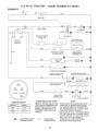
Schematic ........................................ 27
Brake ............................................... 21
Carburetor ........................................ 23
Wiring Diagram ...................................28
Mower
Engine:
Front*To-Back ............................ 20
Air' Filter ......................................
17
Side-To-Side ............................. 20
Air Screen ................................................
18
Throttle Control Cable .....................23
Cooling Fins ..........................................
18
Oil Change .................................... 17
Air Filter, Engine .............................
17
Oil Level ............................................13
Air Screen, Engine .............................. t8
Oil Type ...................................... 13,17
AssembZy .........................................
7-I0
Preparation .................................
13
Repair Parts ................................44-5t
B
Starting .........................................
14
Storage ........................................
24
Battery:
Charging ..................................................
8
F
Cleaning ......................................... 16
Installation ......................................... 9
Filter:
Levels ..................................................
8,16
Air Filter ............................................ 17
Preparation ..........................................8
Fuel ..........................................................
18
Starting with Weak Battery .............22
Fuel:
Storage ............................................ 24
Type .................................................. 13
Terminals .......................................... 16
Storage ..................................._.............
24
Belt:
Fuse
...................................................
22
Motion Drive
Oil:
Removal/Replacement
...............2t
Mower Belt(s)
Removal/Replacement
.................
21
Blade:
Sharpening ..............................................
16
Replacement ................. ................ 16
Brake Adjustment ......................................21
Service and Adjustments .............. 19-23
Carburetor. ........................................ 23
Fuse
22
Hood Removal!installation
.......... 22
Motion Drive Belt
Removal/Replacement
............ 21
Mower Belt(s)
RemovaltReplacement
............. 21
Mower Adjustment
Front-to-Back ............................. 20
Side-to*Side ...................................20
Mower Remova]/fnsta]lation
.......... 19
Tire Ca_e ....................................8,16,22
Slope Guide Sheet .................................. 55
Spark Plug(s) ........................................... t 8
Specifications .......................................... 3
Starting the Engine ......................... 13q4
Steering Wheel ..................................... 7,22
Stopping the Tractor .................................12
Storage ...................................................... 24
C
Carburetor Adjustment .......................... 23
Controls, Tractor, .................................... 11
Customer Responsibilities ................15-18
Engine:
Air Filter ................................................
17
Air Screen ............................
18
Cooling Fins ............................ 18
Engine Oil .............................. 13,17
Fuel Filter ..................................... 18
Spark Plug(s) .............................. 18
Tractor:
Battery ......................................
16
Blade ........................................... 16
Lubrication Chart ..........................15
Maintenance Schedule ...............15
Tire Care ............................. 8,16,22
Transaxte .................................... 17
Cutting Height, Mower, ............................12
H
Hood Removal/installation
.................... 22
L
Leveling Mower Deck ........................... 20
Lubrication:
Chart .........................................................
15
Engine ................................................17
M
Maintenance Schedule ............................15
Mower:
Adjustment, Front4o-Back ................
20
Adjustment, Side-to-Side
........... 20
Blade Replacement ....................... 16
Blade Sharpening .............................16
Cutting Height .......
:........................
12
Installation ..............................................
19
Operation ................................................
13
Removal .......................................
19
Mowing Tips ........
;.............................................
14
Muftier ..................................................................
18
Spark Airester ...............................3,36
Cold Weather Conditions .............
13,17
Engine ...........................................
17
Storage .............................................. 24
Operation ..........................................................
11-!4
Operating Mower .........................................
13
Options:
Accessories ...................................
5
Spark Arrester .............................. 3,36
P
Parking Brake ................................... 1lq2
Parts Bag ...............................................
6
Parts, Replacement/Repair
............ 28-45
Product Specifications ..................................
3
R
Repair Parts ..........................................
28-45
S
Safety Rules ............................................... 2
Seat ........................................................... 8
...................................................
T
Throttle Control Cable Adjustment .......23
Tires ................................................. 8,16,22
Troubleshooting Chart .......................25_26
Transaxle ................................................ 17
W
Warr&nty ...........................................
3
Wiring Diagram ............................................
28
Wiring Schematic ..............................
27
,,in,=lr
AOOESSOR ESAND
, i , ,,
ATTACH
i
ENTS
,,rl,l,lU,,U,,,, '1' I
These accessories and attachments were available through most Sears retail outtets and service centers when the tractor was purchased,
Most Sears stores can order these items for you when you provide the model number of your tractor,
ENGINE
SPARK PLUG
MAINTENANCE
GAS CAN
ENGINE OIL
FUEL STABILIZER
BLADES
BELTS
PERFORMANCE
Sears offers a wide variety of attachments that fit your tractor.
you. This list was current at the time of publication; however,
may be made in these attachments, or some may no longer
accessories
and attachments
that are available for your
Most of these attachments do not require additional hitches
attaching and detaching
Many of these are listed below with brief explanations of how they can help
it may change in future years - more attachments may be added, changes
be avai]abfe or fit your model Contact your nearest Sears store for the
tractor.
or conversion kits (those that do are indicated) and are designed for easy
AERATOR promotes deep root growth for a healthy lawn Tapered 2 5-inch steel spikes mounted on !04nch diameter discs
puncture holes in soil at close intervals to let moisture soak in
Steei weight tray for increased penetration.
BAGGER lets you collect
grass clippings and _eaves for a
healthier, nearer looking lawn Two Permanex containers held
30-gallon plastic bags..
BUMPER protects front end of tractor from damage
CARTS make hauling easy
Variety of sizes availabFe, plus
accessories such as side panel kits, tool caddy, cart cover,
protective mat and dolly
CORING AERATOR takes small plugs out of soil to allow moisture and nutrients to reach grass roots. 36-inch swath
24
hardened steel coring tips 150 Ib capacity weight tray.
EASY OIL DRAIN VALVE makes oil changes easier, faster
FRONT NOSE ROLLER canters in front of mower deck to reduce
chances of "scalping '_on uneven terrain.
GANG HITCH lets you tow 2 or 3 pull-behind attachments at once,
such as sweepers, dethatchers, aerators (not for use with rollers,
carts or other heavy attachments).
GAUGE WHEELS on both sides of the mower deck reduce
chances of "scalping" on uneven terrain For mower decks not so
equipped..
MULCH RAKE/DETHATCHER
loosens soi! and flips thatch and
matted leaves to lawn surface for easy pickup. Twenty spring tine
teeth. Usefulto prepare bare areas forseedlng. Available for front
or rear mounting.
HIGH PERFORMANCE
REEL-ACTION
SPRING TINE DETHATCHER covers 36-inch wide path and
tosses thatch into large hopper Mounts behind tractor
MULCHING CLOSE-OUT PLATE KIT, once installed, lets you
mulch, discharge or bag clippings (bagger optional) wilhout
changing blades For models not equipped as 3-in-1 Convertible
mowers
See "MOWER" in the Repair Pads section of this
manual
RAMP TOPS AND FEET tel you load and unload tractor from a
pickup truck. Use with 2 x 8 or 2 x t0 lumber
ROLLER for smoother lawn surface.
36-inch wide, 18-inch
diameterwater4ightdrumholdsupto3901bs
ofweight Rounded
edges prevent harm to turf Adiustabfe scraper automatically
cleans drum
SNOW B LADE for snow removal only. 14-inch high, 42-inch wide
blade clears 38-inch path when angEed left or right Raises, lowers
with side lever Adjustable skids; repfaceable, reversible scraper
bar (Use with tire chains and wheel weights and!or rear drawbar
weight. )
SNOWTHROWER has 40-inch swath Drumqype auger handles
powdery and wet/heavy snow. Mounts easily with simple pin
arrangement. Discharge chute adjusts from tractor seat. 6-inch
diameter spout discharges snow 10 to 50 feet Lift controlled at
tractor seat. (Use with chains and wheeI weights and/or rear
drawbar weight..)
SPRAYERS use !2-volt DC electric motor that connects to the
tractor battery or other 12-volt source.
Includes booms for
automatic spraying and hand held wand for spot spraying Wand
has adjustable spray pattern
For applying herbicides, insecticides, fungicides and liquid fertilizers.
SPREADER/SEEDERS
make seeding, fertilizing, and weed kilEing easy. Broadcast spreaders are also useful for granular deicers and sand
SWEEPERS
let you collect grass clippings and leaves.
TILLER has 5 hp engine and 364nch swath to prepare seed beds,
cultivate and compost garden residue Tiller has its own builtqn
lift and depth control system and does NOT require a sleeve hitch
Fits anylawn, yard or garden tractor Simply hook up to the tractor
drawbar and go!
Optional
accessories
convert unit for
dethatching, aerating, hilling without tools
TIRE CHAINS are heavy duty; c_osely spaced extraqarge cross
links give smooth ride, outstanding traction
TRACTOR CAB has heavy duty vinyl fabric over tubular steel
frame, ABS plastic top; clear plastic windshield offers 360 degree
visibiJlty Hinged metal doors with catch_ Keeps operator warm
and dry Remove vinyl sides and windshie}ds for use as sun
protector in summer. Optional accessories
include:
tinted/
tempered solid safety glass windshield with hand operated wiper;
12-volt amber caution light for mounting on cab top.
VACS for powerful collection of heavy grass clippings and leaves
Optional wand attachment
to pick up debris in hard-to-reach
places VAC/CHIPPER includes a chipper-shredder.
WEIGHT BRACKET for drawbar for snow removal applications.
Uses (1) 55 _b ,,_eight.
WHEEL WEIGHTS {or re_.,_wheels provide needed traction for
snow removal or dozing ,_,_,
_vy maiedals
u,
,,, ,U,=lU-i.
,
n
lU="M'I",IIIIr'Illl
CONTENTS OF HARDWARE PACK
,i i ,,, ,11,11,
i,,111
Parts Bag contents
;.;;;_,_
Parts packed separately in carton
shown full size
ii
i ,n i ,,, nlHin,!,
Seat
Battery acid
(1) Knob
Mulcher
Plate
(1) Shoulder Bolt
5/16-18
Steering
Wheel
Battery
H
(1) Washer
17/32 x 1-3/16 x 12 Gao
Owner's Manual
Parts Bag
,,, u i ,, i Ull,,
i i,u,,uu .........................
Parts bag contents
@
(2) Lock Washers
(2) Screws #10 x 5/8
.....
_
#10
(2) Weld Nuts #10
i
@
(2) Hex Bolts 1/4-20 x 3/4
(¢
(2) Centerlock Nuts
(2) Hex Nuts 1/4-20
(2) Keys
Terminal Guard
[
r ''i.........
i'_I_
.................. i[
(2) Lock Washers
1/4
@
(2) Wing Nuts
..............
Sleeve
Steering
(2) Battery Carriage Bolts 1/4-20 x 7-1/2
(2) Washers
9/32,,,,×,,5/8x 16 Ga.
full size
, ,ii,,u.....
Steering
Wheel
Insert
3/16 x 3/4 x 16 Gauge
CP_!It!!lII!llU
n,u
©
(2) Shoulder'
Bolts
x(2)7/8
x 14 Gauge
Washers
3/8
(2) Washers
not shown
15 ° Slope Sheet
1/4-20
....
lU,,,,,, i :, u,,
6
i ......
i1,,i,,,,111
}'
Battery Caps
and Instructions
ASSEMBLY
Your new tractor has been assembled at the factory with exception of those parts left unassembled for shipping purposes
To ensure safe and proper operation of your tractor all parts and hardware you assemble must be tightened securely Use
the correct tools as necessary to insure proper tightness.
TOOLS
REQU1RED
FOR ASSEMBLY
A socket wrench set will make assembly easier
wrench sizes are listed,
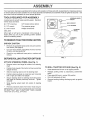
STEERING
WHEEL
Standard
(2) 7/16" wrenches
3/4" Socket w/drive ratchet
(1) 1/2" wrench
Tire pressure gauge
(1) 9/16" wrench
Phillips Screwdriver
-._
HEX LOCKNUT
1
FLAT WASHER
'_--
_
STEERING
Utility knife
When right or left hand is mentioned in this manual, it
means when you are in the operating position (seated
behind the steering wheel).
TEERING
TO REMOVE TRACTOR
UNPACK
FROM CARTON
,
WHEEL
STEERING
ADAPTER
CARTON
•
Remove all accessible loose parts and parts cartons
from carton (See page 6).
•
Cut, from top to bottom, along lines on all four corners
of carton, and lay panels flat,
o
Check for any additional loose parts or cartons and
remove.
STEERING
WHEEL
Remove locknut and large flat washer from steering
shaft,,
•
Position front wheels of the tractor so they are pointing
straight forward
•
Slide the steering sleeve over the steering shaft
•
Position steering wheel so cross bars are horizontal
(left to right) and slide onto adapter,
•
Secure steering wheel to steering shaft with locknut
and large flat washer previously removed
Tighten
securely.
Snap steering wheel
wheel,
/
_
•
SHAFT
/
_
/
STEERING
//SLEEVE
/
FIG. 1
(See Fig. 1)
o
•
,,,
_,
BEFORE ROLLING TRACTOR OFF SKID
ATTACH
,
insert into center of steering
o
Remove protective ptastic from tractor hood and griFL
IMPORTANT: CHECK FOR AND REMOVE ANY STAPLES
IN SKID THAT MAY PUNCTURE
TIRES WHERE
TRACTOR IS TO ROLL OFF SKID
TO ROLL TRACTOR
OFF SKID (See Fig. 8)
o
Raise attachment lift lever to its highest position,,
.
Release parking brake by depressing clutch/brake
pedal,.
Place gearshift lever in neutral (N) position
Roll unit backwards off skid,
•
.
•
Remove banding holding discharge guard up against
tractor
inl,lulu"n
lu nu!l
i
i
ASSEMBLY
HOW TO SET UP YOUR TRACTOR
PREPARE
BATTERY
u,m,ull
&
ilUll
lUl
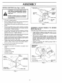
SEAT (See Fig. 3)
Adjust seat before tightening adjustment knob
(See Fig. 2)
................
CAUTION:
INSTALL
u
i
Wear eye and face shield.
Wash hands or clothing immediately if
accidentally in contactwith battery acid,
Do not smoke.
Fumes from charged
battery acid are explosive,
Read the instructions included with the
battery vent caps, Always wear gloves,
clothing and goggles to protect your
hands, skin and eyes.
°
•
Remove cardboard packing on seat pan,
Place seat on seat pan and assemble shoulder bolt
.
Assemble adjustment
Do not tighten,
o
Tighten shoulder bolt securely
o
Lower seat into operating position and sit on seat,
o
Slide seat until a comfortable position is reached which
allows you to press clutch/brake pedal all the way
down_
°
Get off seat without moving its adjusted position.
°
Raise seat and tighten adjustment knob securely
Your tractor has a battery charging system which is sufficient for normal use,. However, periodic charging of the
battery with an automotive charger' witt extend its life,
o
See instructions packed with vent caps in parts bag
o
Fill battery with acid, Fill each cell until it reaches the
bottom of the vent wells Do not overfill,.
knob and flat washer loosely,
SEAT
k
SEAT PAN
SHOULDER
BOLT
Allow battery to stand and settle for at least thirty
minutes
After standing, check the battery cell acid
level If below the vent wells, add more acid until the
correct level is reached,,
While battery is standing (after adding acid) and later, while
battery is being charged, continue with assembly of tractoL
IMPORTANT:
TO MAXIMIZE THE LIFE QF YOUR
BATTERY, IT 1S NECESSARY THAT THE BATTERY BE
CHARGED
BEFORE USE FAILURE TO CHARGE
BATTERY CAN RESULT IN A SHORTENED BATTERY
LIFE
.
Charge battery at a rate of 6 amperes for I hour Use
a 12 volt battery charger,. Observe all safety precautions required for battery charging
-
Check the acid level after the battery is charged, tf the
acid has fallen below the correct level, add distilled or
iron free water
o
Install the vent caps to cover the vent wells,. Wash the
top of the battery with water to remove any acid, then
wipe dry.,
-
Check battery case for' leakage to make sure that no
damage has occurred in handling.
-
Dispose of excess battery acid. Neutralize acid for
disposal by adding it to two gallons of water in a five
gallon plastic container, Stir with a wooden or plastic
paddle while adding baking soda until the addition of
more soda causes no more foaming
-
, FLAT WASHER
ADJUSTMENT
KNOB
FIG. 3
CHECK
-
Reduce tire pressure to PSI shown in "PRODUCT
SPECIFICATIONS" on page 3 of this manual.
CHECK
DECK
LEVELNESS
For best cutting results, mower housing should be properly
leveled
See "TO LEVEL MOWER HOUSING" in the
Service and Adjustments section of this manual,
CHECK
BELTS
FOR
PROPER
POSITION
OF
ALL
See the figures that are shown for replacing motion and
mower blade drive belts in the Service and Adjustments
section of this manual
Verify that the belts are routed
correctly,
VENT CAP
VENT WELL
CHECK
BATTERY
CELL ACID
LEVEL
FIG, 2
PRESSURE
The tires on your tractor were overinflated at the factory for
shipping purposes
Correct tire pressure is important for
best cutting performance
Follow instructions on how to install battery,
CUT AWAY VIEW
TIRE
BRAKE
SYSTEM
After you learn how to operate your tractor, check to see
that the brake is properly adjusted. See "TO ADJUST
BRAKE" in the Service and Adjustments section of this
manual
8
ASSEMBLY
INSTALL
BATTERY
(See Figs. 4 and 5)
WING NUTS _
H'H'I'HHHH' U'
TERMINAL
CAUTION: Do not short battery terminals, Before installing battery, remove
BATTERY
....
rings, etc.
metal bracelets,
wristwatch
bands,
Positive terminal must be connected
first to prevent sparking from accidental grounding.
o
Lift hood to raised position.
o
Be sure battery drain tube has not come loose and is
securely attached to drain in battery tray
o
Lower battery into battery tray with terminals to front of
tractor.
•
First connect RED battery cable to positive (+) battery
terminal with hex bolt, flat washer, lock washer and hex
nut as shown. Tighten securely
•
Connect BLACK grounding cable to negative (-) battery
terminal with remaining hex bolt, flat washer, lock
washer and hex nut, Tighten securely
.
Slide the two battery bolts through the terminal guard
and start the wing nuts onto the threads,
•
Position terminal guard over battery as shown, lower
battery bolts into key holes and slide square shafts of
battery bolts into slots of key holes.
.
Tighten wing nuts by hand making sure battery bolts
remain in slots of the key holes in the battery support.
Be sure terminal access doors are closed,
.
_'_ _.._"
/ _'_TERMINAL
___ACCESS
UUL, "-___
.
I It I!
_
DOORS
_ VENTCAPS
_" KEY HOLE
FIGo 5;
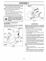
ASSEMBLE
GAUGE
DECK (See Fig. 6)
WHEELS
TO MOWER
Assemble gauge wheels with tractor on a flat tevel surface,
.
Adjust mower to desired cutting height (See 'q-O AD,JUST MOWER CUTTING HEIGHT" in the Operation
section of this manual).
•
With mower in desired height of cut position, gauge
wheels should be assembled so they are slightly off the
ground. Install gauge wheel in appropriate hole with
shoulder bolt, 3/8 washer and 3/8-16 Iocknut and
tighten securely.
°
Repeat for opposite side installing
same adjustment hole.
gauge wheel in
Use terminal access doors for:
•
Inspection
ware).
for secure connections
.
Inspection for corrosion.
.
Testing battery.,
.
Jumping (if required).
•
Periodic charging,
(to tighten hard-
FLAT
WASHER
LOCK
WASHER
GAUGE WHEEL
MOUNTING
BRACKET
3_-16
LOCKNUT
(POSITIVE)
3/8 WASHER
HEX N UT ,,.,._
_SHOULDER
GAUGE WHEEL
BOLT
FIG. 6
BOLT
(NEGATIVE)
BLACK CABLE
DRAIN TUBE
FIG_ 4
,IH,I
iNSTALL MULCHER
o
linil-
i,,,ll
H i
,
i
PLATE (See Figs.7A & 7B)
install two latch hooks to mulcher plate using screw,
washer, lock washer, and weld nut as shown.
NOTE: Pre-assemb[e weld nut to latch hook by inserting
weld nut from the top with hook pointing down
•
Tighten hardware securely.
°
Raise and hold deflector shield in upright position.
•
o
Place front of mulcher plate over front of mower deck
opening and slide into place, as shown.
Hook front latch into hole on front of mower deck.
-
Hook rear' latch into hole on back of mower deck
ill,mlll,ii
iill!
!llHi
,
CAUTION: Do not remove discharge
guard from mower'. Raise and hold
guard when attaching mulcher plate
and allow it to rest on plate while in
operation.
TO CONVERT
DISCHARGING
TO BAGGING
LATCH
FIG. 7B
OR
/CHECKLIST
Simply remove mulcher plate and store in a safe place.
Your' mower is now ready for' discharging or installation of
optional grass catcher' accessory,,
BEFORE YOU OPERATE AND ENJOY YOUR NEW
TRACTOR, WE WISH TO ASSURE THAT YOU RECEIVE
THE BEST PERFORMANCEAND SA TtSFACTION FROM
THIS QUALITY PRODUCT.
HOOK POINTS
DOWN
WELD NUT
FROM THE
PLEASE REVIEW THE FOLLOWING
LOCK
/
All assembly instructions have been completed..
/
No remaining loose parts in carton,
/
Battery is properly prepared and charged,
1 hour at 6 arnps).
/
Seat is adjusted comfortably and tightened securely°
v"
All tires are properly inflated. (For shipping purposes,
the tires were ovefinflated at the factory).
¢"
Be sure mower deck is properly leveled side-to-side/
front-to-rear for best cutting results. (Tires must be
properly inflated for leveling)
/
Check mower and drive belts. Be sure they are routed
properly around pulleys and inside all belt keepers..
/
Check wiring. See that all connections are stilt secure
and wires are properly clamped,
WELD
NUT
_
WASHER
SCREW
LATCH
HOOK
_'LATCH
HOOK
LOCK
WASHER
MULCHER
PLATE
WELD
NUT
I WASHER
WASHER
CHECKLIST:
(Minimum
WHILE LEARNING HOW TO USE YOUR TRACTOR, PAY
EXTRA A TTENTION TO THE FOLLOWING IMPORTANT
ITEMS:
_'_'_'_SCREW
FIG. 7A
v"
Engine oil is at proper level..
,/"
Fuel tank is filled with fresh, clean, regular unieaded
gasoline.
Become familiar with all controls - their location and
function. Operate them before you start the engine.
v"
v"
10
Be sure brake system is in safe operating condition.
i,J_=,J ,
.........
OPERATION
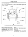
KNOW YOUR TRACTOR
READ THIS OWNER'S
MANUAL
AND SAFETY
RULES
BEFORE
OPERATING
YOUR TRACTOR.
Compare the i[lustrations with your tractor to familiarize yourself with the location of various controls and adjustments, Save
this manual for future reference,
ATTACHMENT
CLUTCH LEVER
THROTTLE/CHOKE
CONTROL
IGNITION SWITCH
- - _
__ _
LIFT LEVER
" _
LIGHT SWITCH
ATTACHMENT
LEVER
CLUTCH/BRAKE
PEDAL
PARKING
LEVER
BRAKE
HEIGHT
ADJUSTMENT
KNOB
GEARSHIFT
LEVER
FIG_ 8
Our tractors conform to the safety standards of the American National Standards Institute°
ATTACHMENT CLUTCH LEVER - Used toengage mower
blades or other attachments mounted to your tractor,
ATTACHMENT LIFT LEVER - Used to raise and lower
mower deck or other attachments mounted to your tractor.
CLUTCH/BRAKE
PEDAL - Used for dectutching
braking the tractor and starting the engine,
HEIGHT ADJUSTMENT
height,
GEARSHIFT
the tractor,
LEVER - Selects the speed and direction of
IGNITION SWITCH - Used to start and stop the engine,,
PARKING BRAKE LEVER - Locks clutch/brake pedal into
the brake position,
and
THROTTLE/CHOKE
CONTROL - Used for starting and
controting engine speed
LIFT LEVER PLUNGER - Used to release attachment lift
lever when changing its position,
KNOB - Used to adjust the mower
LIGHT SWITCH - Turns the headlights on and off
11
i-m-=,=,
OPERATNON
,u
i
:u_J=_=,,,,,
=
i
, i, 11,1
The operation of any tractor can result in foreign objects thrown into the eyes, which can
result in severe eye damage. Always wear safety glasses or' eye shields while operating
your tractor or performing any adjustments or repairs. We recommend a wide vision safety
mask for over the spectacles or Standard safety glasses.
,.
HOW TO USE YOUR TRACTOR
TO SET PARKING
BRAKE
TO MOVE FORWARD
(See Fig. 9)
(See Fig. 9)
o
Depress clutch/brake
and hold
o
Place parking brake lever in "ENGAGED" position and
release pressu re from clutch!brake pedal Pedalshould
rema'n in "BRAKE'pos t'on Make sure park ng brake
will hold tractor secure.
STOPPING
The direction and speed of movement
gearshift lever_
pedal into full "BRAKE" position
(See Fig. 9)
Move attachment clutch lever to "DISENGAGED"
sition.
GROUND
o
•
°
Start tractor with clutch/brake pedal depressed
gearshift lever in neutral (N) position_
-
Move gearshift lever to desired
"DISENGAGED"
POSITION
lever to neutral (N) position.
position
PARKING BRAKE
"ENGAGED"POSITION
NOTE:
Failure to move throttle control to slow (-_,)
position and allowing engine to idle before stopping may
cause engine to "backfire",
•
Turn ignition key to "OFF" position and remove key.
Always remove key when leaving tractor to prevent
unauthorized use,
-
Never use choke to stop engine.
"BRAKE"
POSITION
HEIGHT
ADJUSTMENT
NOTE: Under' certain conditions when tractor is standing
idle with the engine running, hot engine exhaust gases may
cause "browning" of grass. To eliminate this possibility,
always stop engine when stopping tractor on grass areas.
__
position
ATTACHMENT
CLUTCH LEVER
"ENGAGED"
POSITION
THROTTL_CHOKE
CONTROL
Depress clutch/brake pedal into fuit "BRAKE" position.
Move throttle control to stow (,_)
CLUTCHfBRAKE
TO ADJUST
(See Fig. 9)
Operating engine at tess than furl throttle reduces the
battery charging rate.
°
Full throttle offers the best bagging and mower performance.
KNOB
POSITION
MOWER
CUTTING
HEIGHT
The cutting height is controlled by turning the height adjustment knob in desired direction.
(See Fig. 9)
•
PEDAL "DRIVE"
\ "DISENGAGED"
POSITION
FIG. 9
pletely, as described above, before leaving
the operator's
to empty
CAU1"ION:
Always position;
stop tractor
com........
grass catcher, etc.
TO USE THROTTLE
CONTROL
Always operate engine at full throttle
and
po-
DRIVE -
o
Move gearshift
ENGINE -
is controlled by the
.
Slowly release clutch/brake pedal to start movemenL
IMPORTANT: BRING TRACTOR TO A COMPLETE STOP
BEFORE SHIFTING OR CHANGING GEARS. FAILURE
TO DQ SO WILL SHORTEN THE USEFUL LiFE OF YOUR
TRANSAXLE
MOWER BLADES o
AND BACKWARD
•
Turn knob clockwise (f'_l) to raise cutting height,
•
Turn knob
height.
counterclockwise
(F'h)to
lower cutting
The cutting height range is approximately 1-1/2" to 4",, The
heights are measured from the ground to the blade tip
with the engine not running. These heights are approximate and may vary depending upon soil conditions, height of grass and types of grass being mowed.
12
•
The average lawn should be cut to approximately 2-1/2
inches during the coo! season and to over 3 inches
during hot months. For healthier and better looking
lawns, mow often and after moderate growth
.
For best cutting perf0rmance, grass over' 6 inches in
height should be mowed twice
Make the first cut
relatively high; the second to desired height
OPERATION
,i
TO OPERATE
MOWER
(See
Fig.
,
,
,
i
TO TRANSPORT
10)
Your tractor is equipped with an operator presence sensing
switch Any attempt by the operator to leave the seat with
the engine running and the attachment clutch engaged will
shut off the engine.
.
Raise attachment lift to highest position with attachment lift control.
o
When pushing or towing your tractor, be sure gearshift
lever is in neutral (N) position,
•
-
Select desired height of cut
Lower mower with attachment lift controt.
.
Do not push or tow tractor at more than five (5) MPH
•
Start mower blades by engaging attachment
control
•
TO STOP MOWER BLADES - disengage attachment
clutch control.
CAUTION: Do not operate the mower
without either the entire grass catcher,
on mowers so equipped, or the discharge guard in place:
"ENGAGED"
POSITION
NOTE: To protect hood from damage when transporting
your tractoron a truck or a trailer, be sure hood is closed and
secured to tractor, Use an appropriate means of tying hood
to tractor (rope, cord, etc_)
clutch
BEFORE
!
I
I
i
CHECK
ATTACHMENT
LIFT LEVER HIGH
ENGINE
THE ENGINE
OIL LEVEL
(See Fig. 17)
-
The engine in your tractor has been shipped, from the
factory, already filled with summer weight oil
•
Check engine oil with tractor on level ground
•
Unthread and remove oil fill cap!dipstick; wipe oil off,
Reinsert the dipstick into the tube and rest oil fill cap on
the tube. Do not thread the cap onto the tube. Remove
and read oil level. If necessary, add oil untit "FULL"
mark on dipstick is reached, Do not overfilL
•
For cold weather operation you should change oil for
easier starting (See "OIL ViSCOSiTY CHART" in the
Customer Responsibilities section of this manuat).
o
To change engine oil, see the Customer Responsibilities section in this manual
ATTACHMENT
"DISENGAGED"
POSITION
CLUTCH LEVER
STARTING
ADD GASOLINE
(/'_
=
Fill fuel tank. Use fresh, clean, regular unleaded
gasoline. (Use of leaded gasoline will increase carbon
and lead oxide deposits and reduce valve life)
IMPORTANT: WHEN OPERATING IN TEMPERATURES
BELOW 32°F(0°C), USE FRESH, CLEAN WINTER GRADE
GASOLINE TO HELP INSURE GOOD COLD WEATHER
STARTING
DISCHARGE
GUARD
FIG. 10
TO OPERATE
I
WARNING:
Experience indicates that alcohol blended
fuels (called gasoho! or using ethanol or methanol) can
attract moisture which leads to separation and formation of
acids during storage
Acidic gas can damage the fuel
system of an engine while in storage_ To avoid engine
problems, the fuel system should be emptied before storage of 30 days or longer. Drain the gas tank, start the
engine and let it run until the fuel lines and carburetor are
empty. Use fresh fuel next season. See Storage Instructions for additional information
Never use engine or
carburetor cleaner products in the fuel tank or permanent
damage may occur
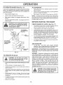
ON HILLS
hills
with slopes
greater
and
CAUTION:
Do not
drive than
up or15°down
do not drive across any slope.
,
Choose the slowest speed before starting up or down
hills.
•
Avoid stopping or changing speed on hills
•
tf slowing is necessary,
slower position
•
If stopping is absolutely necessary, push clutch/brake
pedal quickly to brake position and engage parking
brake
move throttle control lever to
&
Move gearshift lever to 1st gear. Be sure you have
allowed room for tractor to roll slightly as you restart
movement.
•
To restart movement, siowly release parking brake and
clutch/brake pedal
•
Make all turns slowly
113
CAUTION:
Fill to bottom of gas tank
filler neck. Do not overfill. Wipe off any
spilled oil or fuel. Do not store, spill or
use gasoline near an open flame°
OIPERATJON
TO START
ENGINE
(See Fig. 9)
f
When starting engine for the first time or if engine has run
out of fuel, it wilt take extra cranking time to move fuel from
the tank to the engine,.
o
Depress clutch/brake
°
Place gearshift lever in neutral (N) position
pedal and set parking brake,
°
Move attachment
.
Move throttle control lever to choke (N) position for'
cold engine start. For warm engine start, move throttle
control to fast (._) position
=
insert key into ignition and turn key clockwise to"START"
position and release key as soon as engine starts. Do
not run starter continuously for more than fifteen
seconds per minute, if engine does not start after
several attempts, move throttle control to fast (,1_,)
position, wait a few minutes and try again,
clutch to "DISENGAGED"
position,,
.
When engine starts, move throttte control to desired
position_
o
Allow engine to warm up for a few minutes
engaging drive or attachments,
,,_
FIG. 11
MULCHING
MOWING
TIPS
IMPORTANT:
FOR BEST PERFORMANCE,
KEEP
MOWER HOUSING FREE OF BUiLT-UP GRASS AND
TRASH CLEAN AFTER EACH USE
o
The special mulching blade will recut the grass clip_
pings many times and reduce them in size so that as
they fall onto the lawn they will disperse into the grass
and not be noticed,, Also, the mulched grass will
biodegrade quickly to provide nutrients for the lawn.
Always mulch with your highest engine (blade) speed
as this will provide the best recutting action of the
blades,.
•
Avoid cutting your lawn when it is wet Wet grass tends
to form clumps and interferes with the mulching action
The best time to mow your' lawn is the early afternoon
At this time the grass has dried and the newly cut area
will not be exposed to the direct sun
before
NOTE: If at a high altitude (above 3000 feet) or in cold
temperatures (below 32°F), the carburetor fuel mixture
may need to be adjusted for best engine performance. See
"TO ADJUST CARBURETOR" in the Service and Adjustments section of this manual.
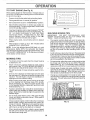
MOWING
,J
T PS
•
Tire chains cannot be used when the mower housing
is attached to unit,.
o
o
Mower should be properly leveled for best mowing
performance See "TO LEVEL MOWER HOUSING" in
the Service and Adjustments section of this manual
The left hand side of mower should be used for trimming,
For best results, adjust the mower cutting height so that
the mower cuts off only the top one-third of the grass
blades (See Fig. 12), For extremely heavy mulching,
reduce you r width of cut on each pass and mow slowly.
•
Certain types of grass and grass conditions may Irequire that an area be mulched a second time to completely hide the clippings, When doing a second cut,
mow across or perpendicular to the first cut path.
•
Change your cutting pattern from week to week. Mow
north to south one week then change to east to west the
next week This wili help prevent matting and graining
of the lawno
•
-
Drive so that clippings are discharged onto the area
that has been cut. Have the cut area to the right of the
machine, This wilt result in a more even distribution of
clippings and more uniform cutting,,
o
When mowing large areas, start by turning to the right
so that clippings will discharge away from shrubs,
fences, driveways, etc. After' one or two rounds, mow
in the opposite direction making left hand turns until
finished (See Fig_ t 1).
•
If grass is extremely tail, it should be mowed twice to
reduce load and possible fire hazard from dried ctippings_ Make first cut relatively high; the second to the
desired height°
.
Do not mow grass when it is wet° Wet grass will plug
mower and leave undesirable ctumps, Allow grass to
dry before mowing,.
o
Always operate engine at full throttle when mowing to
assure better mowing performance and proper discharge of material, Regulate ground speed by selecting a low enough gear to give !he mower cutting
performance as well as the quality of cut desired,
MAX 1/3
FIG. 12
When operating attachments, select a ground speed
that will suit the terrain and give best performance of
the attachment being used.
14
i_ ,,,,i iii ................
CUSTOME
Ill
ESPON
UTIES
ml
FILL IN DATES
REGULAR
.... SERVICE
Check Brake Operation
.,
/_
__0_
_
6_
Check Tire Pressure
e,'4_ _,7
_.,_"
6#4
Check for Loose Fasteners
R
Sharpen/Replace
Mower Blades
............
6/'4
C
Lubrication Chart
6/
V#
6#I
6/
........ 6#/
T ,,check Battery Level!Recharge
0 Clean Batter;/and Terminals
.,
6#4
,
Blade
Belt(s)
Tension
6#15
Adjust Motion Drive Belt(s) Tension
,, ,, ,
.L,.....................
Check Engine Oil Level
$/s
2
"""u'"._H' ""'
':' '"'_ .....
t
6#I
.......
6#_1,2,3
E Clean Air Filter
N
_
I_/
6#42
Clean Air Screen
Inspect Muffler/SparkArrester
6#I
Replace Oil Filter (if equipped)
I_,2
Clean Engine Cooling Fins
Replace Spark Plug
_2
t_
Replace Air Filter Paper Cartridge
_#q'2
....
v"
Replace Fuel Filter
1 - Chaege more often when operating under a heavy load or in high ambienl
2 - Service more often ',,#hen operating in dirty ot dusty conditions
GENERAL
1
_
Change Engine Oil
I
__
CheckTransaxle Cooling
Adjust
N
G
DATES
6#/
T
R
........
SERVICE
lemperatures
I
3 _ If equipped with olt filter, change oil every 50 hours
4 * Replace blades more often when mowing in sandy soil
5 - II equipped with adjustable system
RECOiVIMENDAT[ONS
The warranty on this tractor does not cover items that have
been subjected to operator abuse or negligence.
To
receive fuft value from the warranty, operator must maintain
tractor as instructed in this manual,
Some adjustments wilt need to be made periodically to
properly maintain your tractor_
All adjustments in the Service and Adjustments section of
this manual should be checked at least once each season
o
Once a year you should replace the spark plug, clean
or replace air filter, and check blades and belts for
wear. A new spark plug and clean air filter assure
proper air-fuel mixture and help your engine run better
and last longer..
BEFORE
EACH
(_ ATTACHMENT"
CLUTCH
PIVOT(S)
USE
°
Check engine oil level
o
Check brake operation.
o
•
Check tire pressure
Check for loose fasteners
PIVOTS
(_SAE
30 OR 10W30 MOTOR OIL API -SG
(_)GENERAL
(_REFER
!5
PURPOSE
GREASE
TO CUSTOMER
RESPONSIB|LITIES
"ENGINE"
SECTION
IMPORTANT:
DO NOT OIL OR GREASE
THE PIVOT POINTS
WHICH HAVE SPECIAL
NYLON BEARINGS
VISCOUS LUBRIC/%fTS WILL ATTRACT
DUST AND DIRT THAT WILL SHORTEN
THE LIFE OF THE SELF-LUBR{CATING
BEARINGS,
IF YOU
FEEL THEY MUST BE LUBRICATED,
USE ONLY A DRY. POWDE_ED GRAPH!TE
TYPE [L!3RICANT
SPARINGLY
,
,,
__
CUSTO
--
RESPONSWB L T ES
TRACTOR
o
To check blade balance, you will need a 5/8" diameter
steel bolt, pin, or a cone balancer (When using a cone
balancer, follow the instructions supplied with balancer.)
°
Slide blade on to an un{hreaded portion of the steel bolt
or pin and hold the bolt or pin parallel with the ground,
If blade is balanced, it should remain in a horizontal
position. If either end of the blade moves downward,
sharpen the heavy end until the blade is balanced.
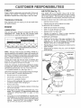
Atways observe safety rules when performing any maintenance.
BRAKE
OPERATION
ff tractor requires more than six (6) feet stopping distance
at high speed in highest gear, then brake must be adjusted.
(See "TO ADJUST BRAKE" in the Service and Adjustments section of this manual)
NOTE: Do not use a nail for balancing blade. The lobes of
the center hole may appear to be centered, but are not.
TIRES
CENTER HOLE
o
Maintain proper air pressure in all tires (See "PRODUCT SPECIFICATIONS" on page 3 of this manual)
.
Keep tires free of gasoline, oil, or insect control chemicals which can harm rubber.
.
BLADE
CARE
For best results mower blades must be kept sharp
place bent or damaged blades°
BLADE
/
/'
5/8" BOLT
OR PIN
Avoid stumps, stones, deep ruts, sharp objects and
other hazards that may cause tire damage.
BLADE
/
/
REMOVAL
Re-
FIG. 14
(See Fig. 13)
BATTERY
°
Raise mower to highest position to allow access to
blades
.
Remove hex bolt, lock washer and flat washer securing
blade
o
Install new or resharpened
towards deck as shown.
o
Reassemble hex bolt, lock washer and flat washer in
exact order as shown.
(See Fig. 15)
Your tractor has a battery charging system which is sufficient for normal use However, periodic charging of the
battery with an automotive charger will extend its life.
=
Acid solution level in each battery cell should be even
with bottoms of vent wells. Add only distilled or iron free
water if necessary Do not overfill.
=
Keep battery and terminals clean,
blade with trailing edge up
°
Keep battery bolts tight°
o Tighten bolt securely (30-35 Ft. Lbs. torque)
IMPORTANT: BLADE BOLT IS GRADE 8 HEATTREATED
•
Keep vent caps tight and small vent holes in caps open
.
Recharge at 6 amperes for 1 hour'.
NOTE: We do not recommend sharpening blade- but if you
do, be sure the blade is balanced.
TO CLEAN BATTERY AND TERMINALS
BLADE
,/_
_'_ _
FLAT
WASHER
Corrosion and dirt on the battery and terminals can cause
the battery to "leak" power.
MANDREL
_l,_,.
TRAILING
/
.
Disconnect BLACK battery cable first then RED battery cable and remove battery from tractor
.
Wash battery with solution of four tablespoons of
baki ng soda to one gallon of water. Be careful not to get
the soda solution into the cells
•
Rinse the battery with plain water' and dry,
o
Clean terminals and battery cable ends with wire brush
until bright.
.
Coat terminals with grease or petroleum jelly
°
Reinstall battery (See "INSTALL
Assembly section of this manual)
CUT AWAY VIEW
FIG, t3
BLADE
Remove terminal guard,
EDGE
'A GRADE 8 HEAT TREATED BOLT CAN BE
IDENTIFIED BY SIX LINES ON THE BOLT HEAD,
TO SHARPEN
•
(See Fig, 14)
The blade can be sharpened with a file or on a grinding
wheel Do not attempt to sharpen while on the mower.
/.
VENT CAP
,
VENT WELL
!-
BATTERY
CELL ACID
LEVEL
Care should be taken to keep the blade balanced° An
unbalanced blade will cause excessive vibration and eventual damage to mower and engine
o
BATTERY"
16
FIG. 15
in the
i
CUSTOM
RESPONSmlBtLJTJES
V-BELTS
AIR FILTER
Check V-belts for deterioration and wear after 100 hours of
operation and replace if necessary, The belts are not
adjustable Replace belts if they begin to s!ip from wear
TRANSAXLE
(See Fig. 17)
Your engine will not run properly using a dirty air filter,
Clean the foam pre-cleaner after every 25 hours of operation or every season. Service paper cartridge every 100
hours of operation or every season, whichever occurs first,
Service air cleaner more often under dusty conditions
•
Remove knob and cover.
COOLING
Keep transaxle free from build-up of dirt and chaff which
can restrict cooling,
.
Remove wing nut and air cleaner from base,
TO SERVICE PRE-CLEANER
ENGINE
•
Slide foam pre-cleaner off cartridge.
LUBRICATION
•
Wash it in liquid detergent and water,
.
Squeeze it dry in a clean cloth.
Only use high quality detergent oil rated with API service
classification SG
Select the oil's SAE viscosity grade
according to your expected operating temperature,
•
Saturate it in engine oil Wrap it in clean, absorbent
cloth and squeeze to remove excess oil
TO SERVICE CARTRIDGE
SAE VISCOSITY GRADES
o
Gently tap the flat side of the paper cartridge to dislodge dirt, Do not wash the paper cartridge or use
pressurized air, as this will damage the cartridge
Replace a dirty, bent, or damaged cartridge,
.
Reinstall the pre-cfeaner (cleaned and oiled) over the
paper cartridge.
.
Reassemble air cleaner, wing nut, cover and tighten
knob securely.
I
_F
_20 _
_C -30°
0°
-20_
TEMPERATURE
30 _
-10"
32 _ 40 _
0_
RANGE ANTICIPATED
6D*
10"
80 _
20"
100 _
30_
40"
BEFORE NEXT OIL CHANGE
FIG. t6
NOTE: Although mu_ti-viscosity oils (5W30, 10W30 etc)
improve starting in cold weather, these multi-viscosity oils
wil! result in increased oil consumption when used above
32°F. Check your engine oil level more frequently to avoid
possible engine damage from running tow on oil,
, COVER
AIR CLEANER
COVER
WING NUT
.RUBBER
GROMMET
FOAM
PRE-CLEANER
Change the oil after the first two hours of operation and
every 50 hours thereafter or at least once a year if the
tractor is not used for 50 hours in one year.
KNOB
Check the crankcase oil level before starting the engine
and after each eight (8) hours of operation, Tighten oil fill
cap/dipstick securely each time you check the oil level
TO CHANGE ENGINE OIL (See Figs,16 & 17)
AIR CLEANER
BASE
Determine temperature range expected before oil change.
All oil must meet API service classification SG.
o
Be sure tractor is on level surface,
o
o
Oil will drain more freely when warm
Catch oil in a suitable container.
o
Remove oil fi!l cap/dipstick, Be careful not to allow dirt
to enter the engine when changing oil
=
Remove drain plug
o
After oil has drained completely, replace oil drain plug
and tighten securely.
o
Refill engine with oil through oil fill dipstick tube. Pour
slowly. Do not overfill, For approximate capacity see
"PRODUCT SPECIFICATIONS"
on page 3 of this
manual
PAPER CARTRIDGE
OIL FILL
CAP/DIPSTICK
AIR
SCREEN
OIL DRAIN
PLUG
FIG. 17
Use gauge on oit fill cap/dipstick for checking level
Insert dipstick into the tube and rest the oil fill cap on the
tube, Do not thread the cap onto the tube when taking
reading
Keep oil at "FULL" line on dipstick Tighten
cap onto the tube securely when finished
17
CUSTOMER
RESPONSiBiLiTiES
M.,...in., ,'11
CLEAN
AER SCREEN
(See Fig. 17)
im,n.ll
I
I
MUFFLER
Air' screen must be kept free of dirt and chaff to prevent
engine damage from overheating. Clean with a wire brush
or compressed air to remove dirt and stubborn dried gum
fibers.
Inspect and replace corroded muffler and spark arrester (if
equipped) as it could create a fire hazard and/or damage.
CLEAN
Replace spark plugs at the beginning of each mowing
season or after every 100 hours of operation, whichever
occurs first. Spark plug type and gap setting are shown in
"PRODUCT SPECIFICATIONS" on page 3 of this manual
AIR INTAKE/COOLING
SPARK
AREAS
To insure proper cooling, make sure the grass screen,
cooling fins, and other external surfaces of the engine are
kept clean at all times..
IN-LINE
Every 100 hours of operation (more often under extremely
dusty, dirty conditions), remove the blower housing and
other cooling shrouds Clean the cooling fins and external
surfaces as necessary. Make sure the cooling shrouds are
reinstalled.
OIL FILTER
(See Fig. 18)
Replace the engine oil filter every season or' every other oil
change if the tractor is used more than I00 hours in one
year
.
FUEL
FILTER
(See Fig. 19)
The fuel filter should be replaced once each season, If fuel
filter becomes clogged, obstructing fuel flow to carburetor,
replacement is required.
NOTE: Operating the engine with a blocked grass screen,
dirty or' plugged cooling fins, and!or cooling shrouds removed will cause engine damage due to overheating.
ENGINE
PLUGS
=
With engine cool, remove filter and plug fue! line
sections.
•
Place new fuel filter in position in fuel line with arrow
pointing towards carburetor.
.
Be sure there are no fuel line leaks and clamps are
properly positioned
o
Immediately wipe up any spilled gasoline
CLAMP
Drain oil from engine crankcase (See "TO CHANGE
ENGINE OIL" in this section of this manual, through
step remove drain ptug).
,
Remove oil filter and wipe off filter adapter
o
Apply a thin coating of new engine oil to the rubber
gasket on replacement oil filter.
•
Install replacement oil filter on filter adapter Turn oil
filter clockwise until rubber gasket contacts the filter
adapter, then tighten filter an additional 1/2 turn.
o
Fill crankcase with new oi! (See "TO CHANGE ENGINE OIL" in this section of this manual). For approximate capacity see "PRODUCT SPECIFICATIONS" on
page 3 of this manual.
•
Start the engine and check for oil leaks. Correct any
leaks before placing engine into full operation..
CLAMP
FUEL FILTER
FIG. 19
CLEANING
OIL FILTER
=
Clean engine, battery, seat, finish, etc. of all foreign
matter.
o
Keep finished surfaces and wheels free of all gasoline,
oil, etc
.
Protect painted surfaces with automotive type wax.
(
We do not recommend using a garden hose to clean your
tractor unless the electrical system, muffler, air filter' and
carburetor are covered to keep water out. Water in engine
can result in a shortened engine life.
FIG. 18
18
SERVICE AN
i
ADJUSTMENTS
i
.........................................
i,,,,,i,,,
i ill i,
i, ii i i i i
CAUTION:
o
o
o
o
.
o
i
BEFORE PERFORMING
ANY SERVICE OR ADJUSTMENTS:
Depress
clutch/brake
fully(N)and
set parking brake.
Place gearshift
lever inpedal
neutral
position.
Place attachment clutch in "DISENGAGED"
position.
Turn ignition key "OFF" and remove key.
Make sure the blades and all moving parts have completely stopped.
Disconnect spark plug wire from spark plug and place wire where it cannot come in contact with
plug.
i
.................................................................
TRACTOR
TO REMOVE
MOWER
(See Fig. 20)
LEVER
Mower will be easier to remove from the right side of tractor
o
°
CLUTCH
Place attachment clutch in "DISENGAGED" position,,
Move attachment Iift lever forward to lower mower to its
lowest position,
°
Roll belt off engine pulley.
,
Disconnect clutch rod from clutch lever by removing
retainer spring
°
Disconnect anti-sway bar from chassis bracket by
removing retainer spring,
o
Disconnect suspension arms from rear deck brackets
by removing retainer springs
•
Disconnect front links from deck by removing retainer
springs°
o
Raise lift lever to raise suspension arms Slide mower
out from under tractor
SUSPENSION
ARMS
MOWER
RETAINER
SPRING
ANTI-SWAY
Raise attachment
o
Slide mower under tractor with discharge guard to right
side of tractor
•
Lower lift lever to its lowest position.
-
Install mower in reverse order of removal instructions,
BAR
RETAINER
SPRINGS
(BOTH SIDES)
(See Fig. 20)
°
PULLEY
_RETAINER
SPRINGS
(BOTH SIDES
IMPORTANT:
IF AN ATTACHMENT OTHER THAN THE
MOWER IS TO BE MOUNTED TO THE TRACTOR, THE
R.H.AND L,H. SUSPENSION ARMS MUST BE REMOVED
FROM TRACTOR
TO INSTALL
SPRING
lift lever to its highest position
FIG. 2O
19
SERVMCE AND ADJUSTMENTS
TO LEVEL
MOWER
HOUSING
To obtain the best cutting results, the mower housing
should be adjusted so that the front is approximately 1/4" to
3/4" lower than the rear when the mower is in its highest
position.
Adjust the mower while tracto_ is parked on level ground or
driveway.
Make sure tires are propedy inflated (See
"PRODUCT SPEC! FtCATIO NS" on page 3 of this manual).
If tires are over or underinf]ated, you will not properly adjust
your mower,.
SIDE-TO-SIDE
ADJUSTMENT
(See Figs. 21 and 22)
o
Raise mower to its highest position,
o
At the midpoint of both sides of mower, measure height
from bottom edge of mower to ground_ Distance"A" on
both sides of mower shoutd be the same or within 1/4"
of each other.
.
If adjustment is necessary, make adjustment on one
side of mower only,
•
To raise one side of mower, tighten lift link adjustment
nut on that side,.
°
To lower one side of mower, loosen lift link adjustment
nut on that side,.
NOTE: Three furl turns of adjustment
mower height about 1/8"
•
Recheck measurements
Check adjustment on right side of tractot_ Measure distance "D" directly in front and behind the mandrel at bottom
edge of mower housing as shown.
•
Before making any necessary adjustments, check that
both front links ate equal in length° Both links should
be approximately 10-3/8"..
-
If links are not equal in length, adjust one link to same
length as other link.
°
To lower front of mower loosen nut "E" on both front
links an equal number of turns
When distance "D" is 1/4" to 3/4" lower at front than
rear, tighten nuts "F" against trunnion on both front
links
.
•
To raise front of mower, loosen nut"F" from trunnion on
both front links. Tighten nut "E" on both front links an
equal number of turns.
°
When distance "D" is 1/4" to 3/4" lower at front than
rear, tighten nut"F" against trunnion on both front links:
•
Recheck side-to-side adjustment,
•
Recheck side-to-side adjustment.
nut will change
after adjusting,_
FRONT-TO-BACK ADJUSTMENT (See Figs, 23 and 24)
IMPORTANT: DECK MUST BE LEVEL SIDE-TO-SIDE tF
THE FOLLOWING FRONT-TO-BACK ADJUSTMENT tS
NECESSARY, BE SURETOADJUST BOTH FRONT LINKS
EQUALLY SO MOWER WILL STAY LEVEL SIDE-TOSIDE
BOTTOM EDGE
OF MOWER TO
GROUND
,,
,,,,
_, ,/
MANDREL
BOTTOM EDGE
OF MOWER TO
FIG. 23
BOTH FRONT LINKS MUST BE EQUAL IN LENGTH
FIG. 21
NUT "E"
NUT "F*'_
FRONT LINKS
LIFT LINKADJUSTMENTNUT
TRUNNION
FIG. 24
FIG. 22
2O
ii
i , Ill
',l,,I "1 '
SERVICE AN
i
iml,i
,",,,i,,
ADJUSTMENTS
i
................
TO REPLACE
(See Fig. 25)
MOWER
BLADE
DRIVE
BELT
WITH PARKING
illll
BRAKE "ENGAGED"
The mower blade drive belt may be replaced without tools.
Park the tractor on level surface° Engage parking brake_,
BELT REMOVAL •
Remove tractor from mower (See "TO REMOVE
MOWER" in this section of this manual).
•
Work belt off both mandrel pulleys and idler pulley,
•
Pull belt away from mower,
NUT "A"
JAM NUT
,/
BELT INSTALLATION •
Install new belt in reverse order of removal.
-
Make sure belt is in all pultey grooves and inside all belt
guides.
MANDREL
OPERATING
ARM
IDLER
PULLEY
FIGo 26
TO REPLACE
(See
MOTION
DRIVE
BELT
Fig. 27)
Park the tractor on level surface, Engage parking brake,
For assistance, there is a belt installation guide decal on
bottom side of left footrest,
,
\
MANDREL
PU LLEY
FIG. 25
TO ADJUST
BRAKE
Your tractor is equipped with an adjustable brake system
which is mounted on the right side of the transaxle.
Depress clutch/brake pedal and engage parking brake
Measure distance between brake operating arm and
nut "A" on brake rod
-
If distance is other than 1-1/2", loosen jam nut and turn
nut "A" until distance becomes 1-1/2", Retighten jam
nut against nut "A",
o
Road test tractor for proper stopping distance as stated
above Readjust if necessary, If stopping distance is
still greater than six (6) feet in highest gear, further
maintenance is necessary. Contact your nearest authorized service center/department
o
Remove upper belt keeper.
.
.
Remove belt from stationary idler and clutching idler
Pull belt slack toward rear of tractor, Remove belt
upwards from transaxte pulley by deflecting belt keepers.
',
Pull belt toward front of tractor and remove downwards
from around engine pulley
ENGINE
PULLEY
If tractor requires more than six (6) feet stopping distance
at high speed in highest gear, then brake must be adjusted.
.
Remove mower (See 'q'O REMOVE MOWER" in this
section of this manual )
°
Install new belt by reversing above procedure.,
IMPORTANT:
MAKE SURE UPPER BELT KEEPER IS
POSITIONED PROPERLY BETWEEN LOCATOR TABS
(See Fig. 26)
°
-
CLUTCHING
IDLER
STATIONARY
IDLER
_
TRANSAXLE
PULLEY
FIG. 27
21
II
KEEPER
SERWCE AND ADJUSTMENTS
i.
TO ADJUST
STEERING
WHEEL
iii
i, iliNi
i
...............
ALIGNMENT
TO REMOVE CABLES, REVERSE ORDER
if steering wheel crossbars are not horizontal (left to right)
when wheels are positioned straight forward, remove steering wheel and reassemble per instructions in the Assembly
section of this manual
FRONT
WHEEL
-
BLACK cable first from chassis and then from the fully
charge d battery.
RED cable last from both batteries.
TOE=IN/CAMBER
The front wheel toe-in and camber are not adjustable on
your tractor. If damage has occurred to affect the front
wheet toe-in or camber, contact your nearest authorized
service center/department_
TO REMOVE WHEEL
(See Fig. 28)
.
=
.
°
.
o
FOR REPAIRS
Block up axle securely
Remove axle cover, retaining ring and washers to allow
wheel removaf (rear whee! contains a square key - Do
not lose),
Repair' tire and reassemble_
On rear wheels only: align grooves in rear wheel hub
and axle_ Insert square key
Replace washers and snap retaining ring securely in
axle groove.
Replace axle cover
FIG. 29
TO REPLACE
°
°
WASHERS
o
RING
.
INTERLOCKS
AXLE
ENGINE
(See Fig. 29)
WITH A WEAK
BULB
AND RELAYS
Loose or damaged wiring may cause your tractor to run
poorly, stop running, or prevent it from starting
Check wiring
See electrical wiring diagram in the
Repair Parts section of this manual°
SQUARE KEY
(REAR WHEEL ONLY)
FIG. 28
TOSTART
HEADLIGHT
Raise hood
Pull bulb holder out of the hole in the backside of the
grill
Replace bulb in holder and push bulb holder securely
back into the hole in the backside of the gritL
Close hood°
TO REPLACE
BATTERY
FUSE
Replace with 30 amp automotive-type plug-in fuse.
fuse holder is located behind the dash,
The
,Ll_U,,, ,'N,, I, ....
TO REMOVE HOOD
(See Fig. 30)
ate explosive gases. Keep sparks, flame
and
CAUTION:
smoking Lead-acid
materials batteries
away from
generbatteries.
Always wear eye protection
when around batteries.
If your battery is too weak to start the engine, it should be
recharged.
If "jumper cables" are used for emergency
starting, follow this procedure:
IMPORTANT: YOUR TRACTORIS EQUIPPED WITH A t2
VOLT NEGATIVE GROUNDED SYSTEM
THE OTHER
VEHICLE MUST ALSO BE A I2 VOLT NEGATIVE
GROUNDED SYSTEM. DO NOT USE YOUR TRACTOR
BATTERY TO START OTHER VEHICLES
TO ATTACH JUMPER CABLES -
o
•
Connect each end of the RED cable to the POSITIVE
(+) terminal of each battery, taking care not to short
against chassis.
Connect one end of the BLACK cable to the NEGATIVE (-) terminal of fully charged battery.
Connect the other end of the BLACK cable to good
CHASSIS GROUND, away from fuel tank and battery.
AND GRILL
.
Raise hood.
•
=
Unsnap headlight wire connector°
Stand in front of tractor', G rasp hood at sides, tilt toward
engine and lift off of tractor,
To replace, reverse above procedure.
.
HOOD
22
ASSEMBLY
FIG. 30
SERVmCE AND ADJUSTMENTS
ENGINE
ACCELERATION
TO ADJUST
THROTTLE
(See Fig. 31)
CONTROL
o
CABLE
The throttle control has been preset at the factor*/ and
adjustment should not be necessary. Checkadjustment as
described below before loosening cabfe If adjustment is
necessary, proceed as follows:
,
With engine not running, move throttle control lever
from slow (,.¢_.) to choke (\I) position Slowly move
lever from choke (1\1) to fast (,re,) post on
o
Check to see if hole in throttle lever and hole in speed
control bracket are aligned
°
If holes are not aligned, loosen cable clamp screw and
align the holes by inserting a pencil or a 1/4" drill bit
through both holes
o
Pull throttle cable up to remove slack and tighten cable
clamp screw Remove alignment pencil or drill bit
TO ADJUST
CARBURETOR
TEST-
Move throttle control lever from slow (._)
to fast
position
If engine hesitates
or dies, turn idle
adjusting needle out (counterclockwise)
1/8 turn
peat test and continue to adjust, if necessary,
engine accelerates
smoothly.
(,_)
fuel
Reuntil
High speed stop is factory adjusted
Do not adjust damage may result,
IMPORTANT:
NEVER TAMPER
WITH THE ENGINE
GOVERNOR,
WHICH tS FACTORY
SET FOR PROPER
ENGINE SPEED
OVERSPEEDING
THE ENGINE ABOVE
THE
FACTORY
HIGH
SPEED
SETTING
CAN
BE
DANGEROUS
IFYOUTHINKTHEENGINE-GOVERNED
HIGH SPEED NEEDS ADJUSTING,
CONTACT
YOUR
NEAREST
AUTHORIZED
SERVICE
CENTER/
DEPARTMENT,
WHICH HAS PROPER EQUIPMENT
AND
EXPERIENCE
TO
MAKE
ANY
NECESSARY
ADJUSTMENTS
(See Fig. 32)
CABLE
The carburetor has been preset at the factory and adjustment should not be necessary. However, minor adjustment may be required to compensate fordifferences in fuel,
temperature, altitude or load tf the carburetor does need
adjustment, proceed as follows:
CLAMP SCREW_....._
SPEEDCONTROLBRACKET_
In general, turning the adjusting needles in (clockwise)
decreases the supply of fuel to the engine giving a leaner
fuel/air mixture Turning the adjusting needles out (counterclockwise) increases the supply of fuel to the engine giving
a richer fuel/air mixture
IMPORTANT:
DAMAGE
SEATS 1N CARBURETOR
TURNED tN TOO TIGHT
PRELIMINARY
TO THE NEEDLES AND THE
MAY RESULT tF NEEDLE IS
THROTTLE
FIG. 31
SETTING -
•
Be sure you have a dean air filter and the throttle
control cable is adiusted properly (see above)
•
With engine off turn idle fuel adjusting needle in (clockwise) closing it finger tight and then turn out (counterclockwise) I turn
IDLE SPEED ADJUSTING
SCREW
IDLE FUEL ADJUSTING
NEEDLE
FINAL SETTING o
Start engine and allow to warm for five minutes. Make
final adjustments with engine running and shift/motion
control lever in neutral (N) position
•
Idle speed setting - With throttle control lever in slow
(,_)
position, engine should idle at 1750 RPM If
engine idles too slow or fast, turn idle speed adjusting
screw in or out until correct idle is attained
•
Idle f_el ne,_dle setting - With throttle control lever in
slow i-_._) position, turn idle fuel adjusting needle in
(clockwise) until engine begins to die and then turn out
(counterclockwise) approximately 1/8 to 1/4 turn to
obtain best low speed performance
o
Recheck idle speed
FIGo 32
Readjust if necessary
23
LEVER
....
=
= B
=
__
STORAGE
ENGINE
Immediately prepare your tractor for' storage at the end of
the season or if the tractor wilt not be used for 30 days or
more
FUEL SYSTEM
ml ,ill
IMPORTANT:
IT iS IMPORTANT TO PREVENT GUM
DEPOSITS FROM FORMING IN ESSENTIAL
FUEL
SYSTEM PARTS SUCH AS CARBURETOR, FUEL FILTER,
FUEL HOSE, OR TANK DURING STORAGE.
ALSO,
EXPERIENCE INDICATES THAT ALCOHOL BLENDED
FUELS (CALLED GASOHOL OR USING ETHANOL OR
METHANOL) CAN ATTRACT MOISTURE WHICH LEADS
TO SEPARATION AND FORMATION OF ACIDS DURING
STORAGE.
ACIDIC GAS CAN DAMAGE THE FUEL
SYSTEM OF AN ENGINE WHILE tN STORAGE
CAUTION: Never store the tractor with
gasoline in the tank inside a building
where fumes may reach an open flame
or spark,
Allow the engine to cool
before storing in any enclosure.
TRACTOR
Remove mower from tractor for winter storage° When
mower is to be stored for a period of time, clean it thoroughly, remove all dirt, grease, leaves, etc. Store in a
clean, dry area.
o
Clean entire tractor (See"CLEAN ING" in the Customer
Responsibilities section of this manual).
o
Inspect and replace belts, if necessary (See belt replacement instructions in the Service and Adjustments
section of this manual).
•
Lubricate as shown in the Customer Responsibilities
section of this manual..
o
Be sure that all nuts, bolts and screws are securely
fastened Inspect moving parts for damage, breakage
and wear_ Replace if necessary°
.
Touch up all rusted or chipped paint surfaces; sand
lightly before painting..
Fully charge the battery for storage.
o
After a period of time in storage, battery may require
recharging..
=
=
Drain the fuel tank
°
Start the engine and tet it run until the fuel lines and
carburetor are empty
o
Never use engine or carburetor cleaner products in the
fuel tank or permanent damage may occur.
Use fresh fuel next season.
o
NOTE: Fuel stabilizer is an acceptable alternative in
minimizing the formation of fuel gum deposits during storage. Add stabilizer to gasoline in fue! tank or storage
container. Always follow the mix ratio found on stabilizer
container. Run engine at least 10 minutes after adding
stabilizer to allow the stabilizer to reach the carburetor. Do
not drain the gas tank and carburetor if using fuel stabilizer
ENGINE
OIL
Drain oil (with engine warm) and replace with clean engine
oil. (See "ENGINE" in the Customer Responsibilities
section of this manual).
BATTERY
•
o
CYLINDERS
To help prevent corrosion and power leakage during
tong periods of storage, battery cables should be
disconnected and battery cleaned thoroughly (see "TO
CLEAN BATTERY AND TERMINALS" in the Customer Responsibilities section of this manual).
After' cleaning, leave cables disconnected and place
cables where they cannot come in contact with battery
terminals.
•
Remove spark plug(s).
°
Pour one ounce of oi! through spark plug hole(s) into
cylinder(s).
o
Turn ignition key to"START" position for a few seconds
to distribute oil..
o
Replace with new spark plug(s).
OTHER
°
Be sure battery drain tube is securely attached.
°
Do not store gasoline from one season to another.
=
If battery is removed from tractor for storage, do not
store battery directly on concrete or damp surfaces.
o
Replace your' gasoline can if your can starts to rust°
Rust and/or dirt in your gasoline will cause problems.
o
If possible, store your' tractor indoors and cover it to
give protection from dust and dirt.
•
Cover your tractor with a suitable protective cover that
does not retain moisture. Do not use plastic. Plastic
cannot breathe which allows condensation to form and
will cause your tractor to rust,
IMPORTANT: NEVER COVER TRACTOR WHILE ENGINE
AND EXHAUST AREAS ARE STILL WARM.
24
TROUIBLESHOOT NG
PROBLEM
Will not start
POINTS
CAUSE
I
Fill fuet tank
properly
2
3
4
5
6
7
See "TO START ENGINE" in Operation seclion
Wait several minules before attempting to start
Reptace spark plug
Cieanirep_ace air rifler
Replace fuel filter
Drain fuel tank and carburetor, reffil tank with fresh
8
9
10
Loose or damaged wiring
Carburetor out of adjustment
Engine valves out of adjustment
8
9
t0
gasoline and replace fuel fitter
Check nil wiring
Contact an authorized service center/department
Contact an authorized service canter/department
Hard to start
t
2
3
4
5
6
7
8
Dirty air filter
Bad spark plug
Weak or dead batiery
Dirty fuel filter
Stale or dirty fuel
Loose or damaged wiring
Carburetor out of adjustment
Engine valves out of adjustment
t
2
3
4
5
6
7
8
Clean!replace air filter
Replace spark plug
Recharge or replace battery
Repiace fuel filter
Drain fuel tank and refill with fresh gasoline
Check all wiring
Contact an aulhorized service centeddepartment
Contact an authorized service center/department
Engine wilf not turn over
t
2
3
4
Clutch!brake pedal not depressed
Attachment clutch is engaged
Weak or dead battery
Blown fuse
5
6
7
8
9
Corroded battery terminals
Loose or damaged wiring
Fautty ignition switch
Fauity solenoid or starter
Faulty operator presence switch(es)
1,
2
3
4
5
6
7
8
9
Depress clutch/brake psdal
Disengage attachment clutch
Recharge or replace battery
Replace fuse
Clean battery terminals
Check all wiring
CheckJreplace ignition switch
ChecWreplace sofenoid or starter
Contact an authorized service center/department
1
2
3
4
Weak or dead battery
Corroded baflery terminals
Loose or damaged wiring
Faulty soieneid or starter
1
2
3
4
Recharge or replace battery
Ctean battery terminals
Check a!] wiring
ChecWreptace solenoidor starter
1
2
3
4
5
6
7
8
9
Cutting too much grass!too fast
Throttle in "CHOKE" position
Build-up of grass, leaves and trash under mower,
Dirty air filter
Low oil leve!!dirty oil
Faulty spark plug
Dirty fuel filter
Stale or dirty fuel
Water in fuei
1
2
3
4
5
6
7
8
9
Set in "Higher Cut" position!reduce speed
Adjust throttle control
Clean underside of mower housing
Clean/replace air filler
Check oil ievefichange oil
Clean and regap or change spark plug
Replace fuei filler
Drain fuel tank and refill with fresh gasoline
Drain fuel tank and carburetor, refill tank with fresh
gasoline and replace fuel filter
Connect and tighten spark plug wire
Clean engine air screen/lins
Clean!replace muffler
Check aii wiring
Contact an authorized service center!department
Contact an authorized service center/department
Engine
start
clicks but will not
Loss of power
t
Out of fuel
2
3
4
5
6
7
Engine not "CHOKED"
Engine flooded
Bad spark p_ug
Dirty air fitter
Dirty fuel filter
Water in fuel
CORRECTION
10
t 1
12
13
14
15
Excessive
vibration
1
2
3
Spark plug wire loose
Dirty engine air screen/fins
Dirlyictogged rnuffler
Loose or damaged wiring
Carburetor out of adiustment
Engine valves out of adjustment
Worn, bent or loose blade
Bent blade mandrel
Looseldamaged part(s)
10
11
12
13
14
t5
1
2
Re,lace blade Tighten blade boll
7..:;..ace blade mandrel
3
Tighten loose parlls'_
Peptace damaged parts
r,,i, ,u
-luu
_ ............
_,l,lll,ln
TROUBLESHOOTING
IH i....
i,,
,n
i
PO NTS
uul i,
=HH''II
n
PROBLEM
CAUSE
CORRECTION
Engine continues to run
when operator leaves seat
with attachment clutch
1,
1
Check wiring, switches and connections
If not
corrected, contact an authorized service center/
department
1
2
3
4
5
Replace blade Tighten blade bolt
Level mower deck
Clean underside of mower housing
Replace blade mandrel.
Clean around mandrels to open vent holes
Faulty operator-safety presence control system
JIL'IJ,J
engaged
Ill
Poor cut - uneven
Mower blades will not
rotate
Poor grass discharge
I
I
I
I
1
2
Worn, bent or toose blade
Mower deck not level
3
4
Buildup of grass, leaves, and trash under mower
Bent blade mandrel
5.
Clogged mower deck vent holes from buildup of
grass, {eaves, and trash around mandrels
1
Obstruction
2
3
4_
Worn/damaged mower drive bell
Frozen idler pulley
Frozen blade mandrel
in clutch mechanism
1
2
3
4
Remove
Replace
Replace
Repface
1
2
3.
4
Engine speed too slow
Travel speed too fast
Wet grass
Mower deck not level
!
2
3
4
Place throttle control in "FAST" position
Shift to slower speed.
Allow grass to dry before mowing
Leve_ mower deck
5
6
7
8
Low/uneven tire air pressure
Worn, bent or loose blade
Buildup of grass, leaves and trash under mower
Mower drive belt worn
9
10
11
Blades improperly installed
Improper blades used
Clogged mower deck vent hates from buildup of
grass, leaves, and trash around mandrels
5
6
7
8
9
t0
11
obstruction
mower ddve belt
idler pulley.
blade mandrel
Check tires for proper air pressure
Replacelsharpan blade Tighten blade bolt
Clean underside of mower housing
Replace mower drive belt
Reinstall btades sharp edge down
Replace with blades listed in this manual
Clean around mandrels to open vent holes
i
Headlight(s)
not working
(if so equipped)
Battery will not charge
Engine "backfires"
when turning engine
"OFF'*
1
Switch is "OFF"
1
Turn switch "ON"
2
3
4
5
Bulb(s) burnedout
Faulty !ight swilch.
Loose or damaged wiring
Blown fuse
2
3
4
5
Replace bulb(s)
Check!replace light switch
Check wiring and connections
Replace fuse
t
2
Bad battery ceil(s)
Poor cable connections
1
2
Replace battery
Check/clean all connections
3.
4
Faulty regulator (if so equipped)
Faulty alternator
3
4
Replace regulator,
Reptsce a_temator
1
Engine throttle contro! not set at "SLOW"
position for 30 seconds belore stopping engine.
1
Move throtlle control to "SLOW" position and allow
to idle for 30 seconds before stopping engine
26
15.5 HP 42" TRACTOR
- - MODEL
NUMBER
917.257651
SCHEMATIC
BLACK
BATTERY
RED
WHITE
FUSE 30 AMP
CLUTCH / BRAKE
(PEDAL UP)
BLACK
ATT'MENT CLUTCH
(CLUTCH OFF)
GROUNDING
CONNECTOR
BLACK
i
BLACK
C[
IGNITIONuNIT1
O
SPARK
_-PLUG
BLUE
AFTER FIRE SOLENOID
2B VOLTS AC MIN. @ 3600 RPM
(CHARGING
SYSTEM OISCONNECTED)
CHARGING SYSTEM OUTPUT
3 AMP OC @ 3600 RPM ,
RED
DIODE
DEC]3
BCC]3
)
LIGHTING SYSTEM OUTPUT
5 AMP AC @ 3600 RPM
I ......
POSITION
OFF
SWITCH
]
............
I
CIRCUIT
M+G
ON
J
B+ L
START
]
B + S + L
NON-REMOVABLE
CONNECTIONS
@ 3600 RPM (LIGHTS
OFF)
I
:-O--_...__O,
BROWN
I ......
WIRING INSULATED
CLIPS
NOTE: IF WIRING INSULATED
CLIPS WERE REMOVED FOR
SERVICING OF UNIT, THEY
SHOULD BE REPLACED TO
PROPERLY SECURE YOUR
WIRING
---4_) "---
.2
.........
l
HEADUGHT
SWITCH (OFF)
IGNITION
I
,.,
14 VOLTS AC MIN
ORANGE
t
ALTERNATOR
REMOVABLE
CONNECTIONS
27
_
BLACK
tGHTS
NOTE
YOUR TRACTOR IS EQUIPPED WITH
A SPECIAL ALTERNATOR SYSTEM.
/-77
THE LIGHTS ARE NOT CONNECTED
TO THE BATTERY, BUT HAVE THEIR
OWN ELECTRICAL SOURCE.
BECAUSE OF THIS, THE BRIGHTNESS
OF THE LIGHTS WILL CHANGE WITH
ENGINE SPEED. AT IDLE THE LIGHTS
WILL DIM, AS THE ENGINE 1S
SPEEDED UP, THE LIGHTS WILL
BECOME THEIR BRIGHTEST
28