1
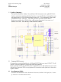
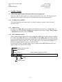
Physics and Astronomy Dept.
UBC
SCUBA-2 Project
Ron Johnson
6/6/2007 12:12 PM
SC2-ELE-S589-502
Version 1.1
Sync Box User’s Guide
Revision History:
Rev. 1.b RJ July 07, 2006 Draft
Rev. 1.c RJ Oct. 25, 2006
Rev. 1.d RJ Dec. 8, 2006 updated block diagram
Rev. 1.1 MA Jun. 7, 2007 added document number and revision history
(For SyncoCmd-V1c and firmware SC2-SyncBox-6c)
-1-
Physics and Astronomy Dept.
UBC
SCUBA-2 Project
Ron Johnson
6/6/2007 12:12 PM
SC2-ELE-S589-502
Version 1.1
Table of Contents
1
SyncBox Summary ....................................................................................................................... 3
1.1 Command IO Processor:........................................................................................................... 3
1.2 Sync Generator CPLD:............................................................................................................. 3
2
Command Summary ..................................................................................................................... 4
3
Command Communications Set-up.............................................................................................. 4
4
Command Input Variables............................................................................................................ 5
4.1 Sync_Length Period Count....................................................................................................... 5
4.1.1 Row_Len period count [default = 64 ] .......................................................................... 5
4.1.2 Num_Rows count [default = 41].................................................................................... 5
4.2 RTS_Mode or FreeRun_Mode [default = FreeRun] ............................................................... 5
4.3 FreeRun_Mode DV period count [default = 47] ...................................................................... 5
SyncBox Status and Error Messages ............................................................................................ 5
5
6
SyncBox Outputs.......................................................................................................................... 6
6.1 MCE Fiber Optic Outputs Manchester Bit Stream Components ............................................. 6
6.1.1 25 MHz Clock, Clk25M ................................................................................................. 6
6.1.2 Address Zero ................................................................................................................... 6
6.1.3 Data Valid Information.................................................................................................. 6
6.2 Data Valid Output To FTS and Polarimeter............................................................................. 7
6.3 Spare RS-485 / 5MHz NRZ Outputs........................................................................................ 7
6.4 Front Panel LEDs ..................................................................................................................... 7
7
SyncBox Inputs ............................................................................................................................ 7
7.1 Commands and Status Serial IO............................................................................................... 7
7.2 Data Valid Input [DV_RTS]..................................................................................................... 7
7.3 Reset Button ............................................................................................................................. 7
8 Other Box Inputs And Outputs..................................................................................................... 7
8.1 MCE Power Supplies Status inputs .......................................................................................... 7
8.2 MCE Power Supplies Enable Outputs...................................................................................... 8
8.3 Spare Opto-TTL Input .............................................................................................................. 8
8.4 Spare TTL-Out and TTL-In...................................................................................................... 8
Updating The Command Softwware ............................................................................................ 8
9
10 Updating The Sync Generation Firmware.................................................................................... 8
11 Power And Environmental Specifications.................................................................................... 8
12 References: ................................................................................................................................... 9
-2-
Physics and Astronomy Dept.
UBC
SCUBA-2 Project
Ron Johnson
6/6/2007 12:12 PM
SC2-ELE-S589-502
Version 1.1
1
SyncBox Summary
The SyncBox distributes Address Zero and Data Valid information to the eight MCE Clock
Cards to synchronise their data collection functions. It is controlled by a Command Processor
with connections to a CPLD [all located on the same PCB]. User commands are input to the
Command Processor via RS-232. The CPLD generates a serial bit stream which is
Manchester encoded with a 25 MHz clock, and contains information for occurrences of
Address_Zero, Data_Valid, and also a Frame Sequence Number.
1.1
Command IO Processor:
Commands are sent to the SyncBox by a 9600 baud RS-232 link to an Atmel AT89C5131A-M,
which is a version of the 80C51 single-chip 8-bit microcontroller.
Input command variables are checked by the Command Processor and loaded one byte at a time
into the Sync Generator CPLD over programmed IO connections with eight bits for data and an
eight bit address.
1.2
Sync Generator CPLD:
Generation and distribution of the Manchester bit-stream, the Data Valid signal, etc., is done
by firmware in an Altera MAXII CPLD.
-3-
Physics and Astronomy Dept.
UBC
SCUBA-2 Project
Ron Johnson
6/6/2007 12:12 PM
SC2-ELE-S589-502
Version 1.1
2
Command Summary
h
?
rl n
nr n
rt
fr n
fn n
go
st
re
dpa
dpu n
epu n
pof
ps
Help. List these commands.
List current SyncBox parameters and status.
set Row_Length to n
n = 1 to 4095
Set Num_Rows to n.
n = 1 to 63
Switch to RTS_Mode.
Switch to FreeRun_Mode with a count of n.
n = 1 to 4095
[if n omitted, then use previous n or default value.]
Set Frame Sequence Number counter to n.
n = 0 to 232-1
Enable Manchester and Data Valid outputs.
Stop. Disable Manchester and Data Valid outputs.
Reset all to defaults.
Disable all ACDCU power units.
Disable ACDCU power unit n.
n = 0 to 7
Enable ACDCU power unit n.
n = 0 to 7
Get ACDCU_onoff control byte.
Get ACDCU status byte.
Notes:
1. Row_Length × Num_Rows must be >= 250.
2. For the SyncBox, Row_Length is counted in cycles of 25MHz
3
Command Communications Set-up
Sending commands to the SyncBox can be done from a PC running Windows by using
HyperTerminal. Start HyperTerminal using the file Synco-Com.ht, or set HyperTerminal as
follows:
COM Port: 9600 baud, 8bits, no parity, 1 stop bit, no flow control.
Emulation: VT100.
Character set ASCII.
Backspace key sends “Ctrl-H, Space, Ctrl-H”.
Append line feeds to incoming line ends.
More than one command may be put on a single input command line, up to a maximum of 12
tokens [commands + arguments], and 80 characters. For repeated use this string of commands
and arguments could be put into a [one line only] text file.
-4-
Physics and Astronomy Dept.
UBC
SCUBA-2 Project
Ron Johnson
6/6/2007 12:12 PM
SC2-ELE-S589-502
Version 1.1
4
Command Input Variables
4.1
Sync_Length Period Count
In the Sync Generator CPLD, Row_Len and Num_Rows count functions are combined into a
single 18 bit counter, but are still settable independently as defined in the next two sub-sections.
To allow time for the output of the 5MHz Data_Valid information, the minimum Sync_Length
permitted will be 250. If (Row_Len x Num_Rows) < 250, an error will be reported.
The SyncBox counts Sync_Length in cycles of 25MHz, and it is assumed the Row_Len value
it receives has been scaled appropriately to match the counting done in the MCE.
4.1.1 Row_Len period count [default = 64 ]
Row_Len is settable from 1 to 4094, and counts cycles of Clk_25M.
4.1.2 Num_Rows count [default = 41]
Num_Rows is settable from 1 to 63, and counts cycles of Row_Len. Output is Addr_Zero
[The sync box does not take into account MCE start rows other than zero. ]
4.2
RTS_Mode or FreeRun_Mode [default = FreeRun]
The commands rt and fr nnnn switch between RTS_Mode and FreeRun_Mode.
In FreeRun_Mode DV_RTS is ignored.
4.3
FreeRun_Mode DV period count [default = 47]
When in FreeRun_Mode the sync box generates it own Data_Valid by down-counting
occurrences of Addr_Zero from a command settable number between 1 and 4095. When the
count goes to zero, it outputs a FreeRun_DV, and re-loads to repeat the count.
If N < 1 an error will be reported. If N is omitted, the default or previous value is used.
If the sync box is in RTS_Mode, FreeRun_DV output is ignored.
5
SyncBox Status and Error Messages
Status Output Format:
Mancho_Enable = ON
DV_Mode = FreeRun_DV
FRUN_COUNT = 47
Row_Len = 64
Num_Row = 41
ACDCU_onoff = 0X00
Some Error Messages:
Synco> xx
WHAT? "xx"
Synco> rl 9999 TOO BIG "9999"
Synco> rl 0 TOO SMALL "0"
Synco> rl xx WHAT? "xx"
-5-
// Unreconized command.
// Command parameter too large.
// or too small.
// could not parse the parameter value.
Physics and Astronomy Dept.
UBC
SCUBA-2 Project
Ron Johnson
6/6/2007 12:12 PM
SC2-ELE-S589-502
Version 1.1
6
SyncBox Outputs
6.1
MCE Fiber Optic Outputs Manchester Bit Stream Components
There are eight FO outputs which will connect to the MCE Clock Cards. The FO outputs are
divided into two groups of four each, for a possible future dual-rate operating mode.
6.1.1 25 MHz Clock, Clk25M
This is the Manchester bit-stream clock. It is always output as a stream of ones, except as
specified below.
6.1.2 Address Zero
Occurrences of Addr_Zero are encoded into the Manchester bit-stream as a single binary ‘0’.
It is output every time the Sync_Length count completes, where Sync_Length = Row_Length
× Num_Rows, and counts cycles of Clk25M.
6.1.3 Data Valid Information
This sequence contains Address Zero, Data_Valid, Status Bits, and a Frame Sequence Number.
It is output when Addr_Zero occurs, and a DV_RTS [or a FreeRun_DV if in FreeRun_Mode]
has occurred during the preceding Sync_Length count. Addr_Zero and DV are encoded into the
Manchester bit-stream as binary ‘00’. They are followed by a 6 bit status word, and then a 32
bit Frame Sequence Number count, for a total of 40 bits.
If two or more DV have occurred during a Sync_Length count the DV_Error bit will be set
[this can only occur when in RTS_Mode].
Address Zero Sync Bit
Data Valid Bit
Status [6 bits]
Frame Sequence Number [32 bits]
MSB
DV Error
FreeRun_Mode
-6-
Physics and Astronomy Dept.
UBC
SCUBA-2 Project
Ron Johnson
6/6/2007 12:12 PM
SC2-ELE-S589-502
Version 1.1
6.2
Data Valid Output To FTS and Polarimeter
This is a buffered version of DV_RTS, or FreeRun_DV if the SyncBox is in FreeRun_Mode.
The DV output for FTS or Polarimeter use will be about 1µsec wide, active low, and is delayed
to occur at the next Addr_Zero, when the manchester bit stream Data Valid and Frame
Sequence Number are output. Both outputs have an RS485 and a TTL output.
6.3
Spare RS-485 / 5MHz NRZ Outputs
There are two spare RS-485 only outputs, which are used for a 5MHz NRZ and clock version of
the Data Valid information. DV_Spare1 has the 5MHz clock output, and DV_Spare 2 has the
NRZ DV information stream.
NOTE: the 5Mhz output contains only the DV info stream, but not the occurrences of
Addr_Zero between DVs
6.4
Front Panel LEDs
FreeRun Mode
This LED is on when the SyncBox is in FreeRun Mode
DV Error
When two or more DV occur during a Sync_Length count the DV_Error LED will be turned on
[this can only occur when in RTS_Mode]. The LED is turned off at the next Addr_Zero.
7
SyncBox Inputs
7.1
Commands and Status Serial IO
One RS-232 IO connection. See Command Communications Set-up.
7.2
Data Valid Input [DV_RTS]
Data_Valid RS-485 input from RTS. Any falling edge will be taken as a DV signal.
7.3
Reset Button
Resets all control states and parameters to the default startup values.
8
Other Box Inputs And Outputs
8.1
MCE Power Supplies Status inputs
Eight inputs driven from optocouplers in the MCE ACDCUs give enabled / disabled
information. This can be checked with the ‘ps’ command, which will reply with an ASCII hex
encoded version of the ACDCU status byte.
Synco> ps
ACDCU_Status = 0X7B
-7-
Physics and Astronomy Dept.
UBC
SCUBA-2 Project
Ron Johnson
6/6/2007 12:12 PM
SC2-ELE-S589-502
Version 1.1
8.2
MCE Power Supplies Enable Outputs
Eight outputs to drive enabling optocouplers in the MCE ACDCUs.
8.3
Spare Opto-TTL Input
A One bit optocoupler isolated input to the Command Processor is available.
[This input is ignored in this version.]
8.4
Spare TTL-Out and TTL-In
These connect to the Sync Generator Module. Inthis version, TTL-Out will get a NRZ version
of the 25MHz synchronizer bit stream information. TTL-In is not used.
9
Updating The Command Softwware
If you want to modify the command software you will need the Keil uVision3 IDE. See the
Keil website www.keil.com for details.
Loading the uVision3 output hex file into the AT89C5131A-M is done using the USB port and
the Atmel Flip utility (FLexible In-system Programmer), which can be downloaded from the
Atmel website, www.atmel.com . [Flip is a Java application, so you will also need the Java
Run-time Environment]
On the SyncBox PCB [with power applied]:
To reprogram BLJB or to get the bootloader to restart so that you can download new code, the
PSEN and RESET switches must be held down while the USB connector is inserted. Reset is
then released followed by PSEN.
In Flip:
Click on the Target Device icon and select AT89C5131.
Make sure that BLJB is unchecked so that the user program will always start after a reset.
Get the hex file. [File -> Load HEX File]
Click on the USB icon and open the UBS connection.
Click on the Run button, and wait while the programming sequence completes.
Click on the Start Application button.
10 Updating The Sync Generation Firmware
11 Power And Environmental Specifications
-
Power supply, Lamda RWS15A, input voltage range 85 to 265VAC, 47 to 440Hz.
Power inlet filter, Corcom 1EEJ1, is rated 1A, 250VAC[max], 50/60Hz
Operating temperature range 0 to +30 C or better.
Time base stable to ± 50 PPM or better over temperature range.
-8-
Physics and Astronomy Dept.
UBC
SCUBA-2 Project
Ron Johnson
6/6/2007 12:12 PM
SC2-ELE-S589-502
Version 1.1
12 References:
[1] Timing and response to Data Valid Pulses [dv_timing.pdf]
M.Halpern 2005-08-11
[2] MCE_Interfaces_SCUBA2_Rev2.pdf
[x] MCE User's Manual
[x] Atmel 89C5131AM data sheet
[x] Atmel 8051 Microcontrollers Hardware Manual
[x] Altera MAXII Device Handbook
-9-