1
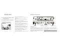
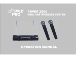
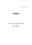
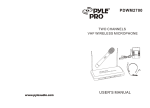
PDWM-2600
www.pyleaudio.com
PDWM-2600
DUAL UHF WIRELESS MICROPH0NE SYSTEM
OPERATION MANUAL
Thanks for your support and trust to us while choosing our wireless
microphone series with excellent quality. To ensure it functions well,
Please read this manual carefully before operation.
PDWM-2600
PDWM-2600
DUAL UHF WIRELESS MICROPH0NE SYSTEM
RECEIVER UNIT/operation
Avoid exposure of the system to rain or moisture.
No user-serviceable parts inside the system. Refer all servicing to a qualified technician only.
Handle the microphone carefully, dropping or other shocks may cause
failure.
Avoid using the system where it may be subjected to heat, such as in
direct sunlight, near radiators or other heat sources.
Should any liquid be spilt on the system, stop using it immediately. It may
be possible to dry the system, but you should have it checked by a qualified technician before using it again.
Take care with the mains power adapter and lead. If damaged in any way,
do not use the system, and refer to a qualified technician for repair.
Only use the system with the supplied components, do not attempt to use
with any other mains power supply adapter .
If the microphone is not going to be used for a time, remove the
battery to prevent leakage. In the event of electrolyte leakage inside the
battery compartment, carefully remove using a damp cloth. Take care not
to get battery electrolyte in contact with your skin, however, if it does,
wash your hands under a running tap. If electrolyte comes into contact
with your eyes, seek medical advice immediately.
Only replace the battery with the same or an equivalent type.
Please dispose of old batteries in an environmentally friendly manner in
accordance with the relevant legislation.
Do not use any solvents to clean any part of the wireless microphone system .
---1---
PDWM-2600
DUAL UHF WIRELESS MICROPH0NE SYSTEM
ANT
MIX
BALANCED
AERIAL. B
SQUELCH
ANT
DC 12V
AF. OUT
BALANCED
OUTPUT JACK
DC POWER IN
AERIAL. A
OPERATION
Switch on the wireless microphone receiver unit by pressing the POWER
switch and the POWER light will illuminate to show the receiver unit is
working. Raise the aerials to the maximum height. The positioning of the
aerials is not critical for performance; ideally it should be fully extended.
Switch ON the microphone, checking that the red LED comes on for a
second and then goes off. When the microphone is ON, the SIGNAL light
will illuminate on the receiver unit.
The wireless microphone is now ready for use; adjust the volume and
tone levels of your amplifier system as well as the receiver & the handheld
mic as required. When the wireless microphone is not being used, turn
OFF the microphone.
Note that switching the microphone on and off can cause interference that
will be heard if the microphone volume level of the amplifier system is
still set high.
---2---
HANDHELD MICROPHONE/DIAGRAM
INSTALLATION
To connect the wireless microphone to your amplifier system:
Refer to the installation diagram below.
UNSCREW BATTERY
COVER TO INSERT
BATTERY
Using the supplied jack-to-jack lead, connect from the AF OUT jack
socket to the MICROPHONE INPUT socket on your amplifier. Plug
the mains power adapter into a suitable mains socket, and plug the
lead connector into the DC 12V input socket.
With voltage selector switch for selecting a suitable AMPLIFIER
one according to different countries.
SPEAKERS
VOLTAGE
SELECTOR SWITCH
BATTERY CONDITION
INDICATOR
MICROPHONE BATTERY.
POWER SWITCH
Unscrew the battery cover at the end of the microphone, Install the provided
9 volt battery, taking care to fit it with the correct polarity connected,
Check the battery by switching the microphone ON, The red LED will come
on for one second and then go OFF, this indicates correct operation, If the
red LED stays ON or is dim, this indicates the battery is low and should be
changed, If the red LED does not come on at all, it indicates the battery
is dead, please change it right now,
---3---
RADIO MIC
RECEIVER UNIT
BATTERY COVER
MIX
ANT
SQUELCH
BALANCED
AF. OUT
ANT
DC 12V
BALANCED
MAINS POWER
ADAPTER
MICROPHONE
---4---
TROUBLE SHOOTING
SPECIFICATIONS
Please read and check the following points before asking for service.
The wireless microphone fails to work:
check the microphone battery by switching the microphone ON, the red LED battery condition indicator should
come on for a second and then go off. If the red LED stays on or is dim, replace the battery. If the red LED fails
to come on, check the battery polarity or change battery.
Check the POWER indicator on the receiver unit is ON, if not, check the mains power adapter is firmly plugged
into a working mains socket.
Check the amplifier system is ON and the microphone controls set correctly.
Check the wireless microphone jack lead is firmly connected into the output socket on the rear panel of the receiver
unit, and into the MIC input socket on your amplifier.
The working range is limited:
Check the microphone battery condition (see above)
Check the aerials are fully extended. Adjust the position of aerials to achieve the best reception.
Feed back (howl-round) is heard:
Check that the microphone is not being used too close to, or in front of, the loundspeakers.
Check the settings of the microphone controls on the amplifier, adjust volume and tone to get the best
sound without any trace of feedback.
---5---
A. OVERALL SYSTEM
1. Oscillation mode:
2. Carrier Frequency Range:
3. Stability:
4. Max Deviation:
5. Dynamic Range:
6. S/N Ratio:
7. T. H. D:
8. Squelch:
9. Frequency Response:
10. Operation range:
Quartz controlled
UHF690-960MHz
+/-0.005%
+/-56KHz with level limiting
>110dB
> 100dB
0.5
"Pilotone & noiselock" dual squelch circuit
60 Hz- 18KHz
200ft
B. REVELVER
1. Sensitivity:
2. Image Rejection:
3. Stability:
4. Audio output:
5. Power supply:
6. Dimensions:
7. Weights:
6dBpv at S/N >70dB
>60dB
>80dB
-12db/600ohm unbalanced and balanced
12V-15VDC/0.5A power supply
10.8"L x 5.9"W x 14.2"H
1.0kg approx
C. WIRELESS MICROPHONE
1. Mike capsule:
2. Antenna:
3. RF Output:
4. Spurious:
5. Battery:
Dynamic microphone
Built-in housing
<10mW
<-40dBC
one 9V battery
---6---