1
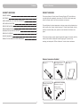
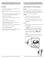
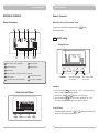
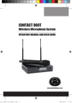
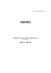
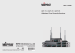
User Guide
ACT-51B / ACT-52B
ACT-51 / ACT-52
WIRELESS MICROPHONE SYSTEMS
All rights reserved. Do not copy or forward without prior approvals MIPRO.
Specifications and design subject to change without notice.
MN 014/01
2 CE 3 8 0 B
WARNING
! IMPORTANT SAFETY INSTRUCTIONS !
1.
Read these instructions.
2.
Keep these instructions.
3.
Heed all warnings.
4.
Follow all instructions.
5.
Do not use this apparatus near water.
6.
Clean only with a dry cloth.
7.
Do not block any ventilation openings. Install in accordance with the
manufacturer's instructions.
8.
Do not install near any heat sources such as radiators, heat registers, stoves, or
other apparatus (including amplifiers) that produce heat.
9.
Do not defeat the safety purpose of the polarised or ground plug: A polarised plug
has two blades with one wider than the other. The wide blade is provided for your
safety. When the provided plug does not fit into your outlet, consult an electrician
for replacement of the obsolete outlet.
1.
FOR OUTDOOR USE:
To reduce the risk of fire or electric shock, do not expose this apparatus to rain or
moisture.
2.
UNDER WET LOCATION:
Apparatus should not be exposed to dripping or splashing and no objects filled with
liquids, such as vases should be placed on the apparatus.
3.
SERVICE INSTRUCTIONS:
CAUTION - These servicing instructions are for use by qualified service personnel
only. To reduce the risk of electric shock, do not perform any servicing other than
that contained in the operating instructions unless you are qualified to do so.
This symbol indicates that dangerous voltage constituting a risk of electric
shock is present within this unit.
10. Protect the power cord from being walked on or pinched particularly at plug,
convenience receptacles, and the point where they exit from the apparatus.
This symbol indicates that there are important operating and maintenance
instructions in the literature accompanying this unit.
11. Only use attachments/accessories specified by the manufacturer.
12. Use only with a cart, stand, tripod, bracket, or table specified by the
manufacturer, or sold with the apparatus. When a cart is used, use
caution when moving the cart/apparatus combination to avoid
injury from tip-over.
& IC - ID
13. Unplug this apparatus during lightning storms or when unused for
long periods of time.
THIS DEVICE COMPLIES WITH PART15 OF THE FCC RULES AND RSS-123 ISSUE2 OF
CANADA. OPERATION IS SUBJECT TO THE FOLLOWING TWO CONDITIONS:
14. Refer all servicing to qualified service personnel. Servicing is required when the
apparatus has been damaged in any way, such as power-supply cord or plug is
damaged, liquid has been spilled or objects have fallen into the apparatus, the
apparatus has been exposed to rain or moisture, does not operate normally, or has
been dropped.
(2) This device must accept any interference, including interference that may cause
undesired operation of the device. This equipment complies with FCC RF radiation
exposure limits set forth for an uncontrolled environment.
15. To reduce the risk of fire or electric shock, do not expose this apparatus to rain or
moisture.
(1) This device may not cause interference.
Disposal
16. Apparatus should not be exposed to dripping or splashing and no objects filled with
liquids, should be placed on the apparatus.
Dispose of any unusable devices or batteries responsibly and in
accordance with any applicable regulations.
Disposing of used batteries with domestic waste is to be avoided!
17. Use only with the battery which specified by manufacturer.
18. The power supply cord set is to be the main disconnected device.
2005-08-13
Batteries / NiCad cells often contain heavy metals such as cadmium(Cd),
mercury(Hg) and lead(Pb) that makes them unsuitable for disposal with
domestic waste. You may return spent batteries/ accumulators free of
charge to recycling centres or anywhere else batteries/accumulators are
sold.
By doing so, you contribute to the conservation of our environment!
Diversity Receivers
Contents
DIVERSITY RECEIVERS
PRODUCT OVERVIEW
PRODUCT OVERVIEW
1
KEY FEATURES
2
MIPRO'S PROPRIETARY "ACT" FUNCTION & OPERATION
3
PART NAMES AND FUNCTIONS
4
RECEIVER INSTALLATION
6
RECEIVER OPERATING TIPS
7
RACKMOUNT INSTALLATION FOR RECEIVERS
8
RECEIVER VFD INTERFACE
10
RECEIVER PARAMETERS
11
GENERAL TIPS FOR IMPROVING SYSTEM PERFORMANCE
17
The receivers feature a full-color Vacuum Fluorescent Display (VFD) which delivers a
very bright light with exceptionally clear contrast. The VFD has a wide viewing angle
and can be viewed clearly in both indoor and outdoor environments.
The panel displays all pertinent parameters on the same screen, audio professionals can
clearly monitor group, channel, working frequency, RF & audio signal strength, diversity
condition, transmitter battery level, squelch level and indication of interference at a
glance.
The diversity technology ensures optimal reception and freedom of movement, while the
industry's first AutoScan & Automatic Channel Targeting (ACT) channel set-up
technology and dual-squelch "PiloTone & NoiseLock" circuits minimize interference.
Receiver Accessories Included
Antenna ×2
Audio Output Cable ×1
(2-pcs for dual channel
model)
Switching Power Supply
with Cable ×1
0
1
Rack-mount kit ×1 set (Rack
Mount Ears ×2, Plugs ×2,
Mounting Screws)
(for single 1/2RU receiver
alone)
User Guide ×1
Diversity Receivers
Diversity Receivers
KEY FEATURES
MIPRO'S PROPRIETARY "ACT" FUNCTION & OPERATION
!
Single-Channel (ACT-51/ACT-51B) and Dual-Channel (ACT-52/ACT-52B) in an EIAstandard 19” ½-rack unit metal chassis.
!
Featuring industry's first full color VFD (Vacuum Florescent Display) on a wireless
receiver.
!
Two levels of brightness adjust automatically during performance and can be viewed
clearly from all angles and day/night environments for easy monitoring.
What is ACT?
“ACT” stands for “Automatic Channel Targeting”. MIPRO developed and patented this
innovative infrared (IR) technology in 2001. MIPRO was the first manufacturer in the
industry to automatically synchronize the frequency selected on the receiver to any ACT
handheld or bodypack transmitter on the same frequency band.
ACT Benefits
!
Diversity technology for optimum reception.
!
No manual frequency adjusting needed, unlike traditional transmitters.
!
Programmable multi-function VFD displays all information on the same screen for
easy control and monitoring.
!
Simple, fast and precise frequency set-up without mechanical errors.
!
!
Fully-electronic push buttons for quick set-up and control.
!
Proprietary high performance RF filter and circuitry improve anti-interference
characteristics and increased compatible systems.
Once the frequency has been set, the data is stored in memory, meaning that
the frequency is set until it is changed by performing the “ACT” function again,
even after powering off.
!
Industry's first ACT function allows rapid and precise transmitter frequency set-up.
ACT Set-Up
!
Ensure a receiver channel is set up and transmitter batteries are fresh, installed
correctly and powered-on.
!
Dual "Pilotone & NoiseLock" circuits minimize interferences.
!
Connects to various MIPRO antenna systems.
!
!
Reliable RF, transparent audio performance and an array of leading-edge features
desired by audio professionals for a host of diverse applications.
Press the ACT button on the receiver to activate the ACT syncing function.
Once activated, the RF meter cursor and working frequency start blinking.
!
Bring ACT handheld or bodypack transmitter within 30cm (12”) of the IR port
on the receiver. The IR port is located between the ACT and ▼ buttons
and indicated by a round-shaped red color spot. The frequency will sync
automatically.
!
When the frequencies are synchronized successfully between the receiver and
transmitter, the RF meter cursor and working frequency stop blinking and the
indicators in the RF meter are lit.
MHz
A
MHz
A
AF
GRP
1
2
3
4
5
6
7
8
BAT
SQ
AF
GRP
1
2
3
4
5
6
7
8
BAT
SQ
CHANNEL 1
CHANNEL 1
<3
2
3
0c
m
(12
or
in .
)
Diversity Receivers
Diversity Receivers
PART NAMES AND FUNCTIONS
Rear Panel:
Front Panel:
ACT-51B / ACT-51
17
ACT-51B /ACT-51
AF
GRP
A
B
1
2
MHz
3
4
5
6
7
8
BAT
SQ
CHANNEL 1
5
1
2
3
6
8
13 14
15
11 12 13 14
15
16
17
ACT-52B / ACT-52
4
7
ACT-52B / ACT-52
AF
GRP
A
B
1
2
MHz
3
4
5
6
7
8
BAT
AF
SQ
CHANNEL 1
1
GRP
A
B
1
2
5
MHz
3
4
5
6
7
8
BAT
6
7
8
9
10
SQ
CHANNEL 2
2
3
5
Rear Antenna “B” Input Connector: The “B” antenna can be installed directly
to this antenna connector which also provides power to an optional antenna
booster.
6 10
Balanced Audio Output Jack: XLR type connector provides balanced audio
output signal from this jack to the mixer, and output level selectable from among
3 levels:
“-6dB” , “0dB” and “+16dB”.
7
Level Switch: “0dB” selection is for “Microphone-level” output. “+10dB” selection
is for “AUX level” output. “-6dB” selection is for half of cable microphone volume.
4
1
Antenna “A” Front Mount: Allows an optional FBC-71 rear-to-front antenna
cable for front antenna placement.
2
Receiver Display: Color VFD.
3
Power On/Off Button: Press and hold button to power on and power off.
4
Antenna “B” Front Mount: Allows an optional FBC-71 rear-to-front antenna
cable for front antenna placement.
11
8 12
Unbalanced Audio Output Jack: 6.3mm (1/4”) PHONE PLUG type connector
provides unbalanced audio output signal from this jack to the mixer. Output level
is selectable from among 3 levels: “-6dB”, “0dB” and “+10dB”.
9
Balanced and Unbalanced Output Switch:Switch to “MIXED” mode, audio
from both channels will be mixed out from BALANCED OUTPUT B 6 and
UNBALANCED OUTPUT B 8 . Switching to “SEPARATE” mode (available in
ACT-52B only) and each channel has individual output.
13
DC Input Jack: For 12 volt DC supply.
14
Rear Antenna “A” Input Connector: The “A” antenna can be installed directly
to this antenna connector which also provides power to an optional antenna
booster.
15
Rack-Mount Brackets: To install the receiver into a standard 19-inch rack case.
16
Auto Power On/Off Switch:
ON position: The receiver turns on automatically when plugged-in during “ON”
position.
OFF position: The receiver needs to be powered-on & off manually by pressing and
holding the Power On/Off Button 3 during “OFF” position.
Note: Default = “OFF” position.
17
4
5
GND Connector: For grounding protection and stabilization.
Diversity Receivers
Diversity Receivers
RECEIVER INSTALLATION
2
8
12
13
1
GND
2
HOT +
3
COLD -
1
3
5
7
11
14
(Figure 2)
!
(Figure 1)
1.
Antenna Installation: Install 2 separate antennas on the antenna sockets
on the rear panel. Illustrated in Figure 1.
2.
Connecting the power supply: Connect the AC/DC adapter cable to the 12V DC
Input Jack 13 illustrated in Figure 1. Next plug the adapter unit into an appropriate
AC outlet with caution to the correct voltage and rating, as shown in Figure 1.
3.
Audio Output Connection:
!
!
!
5
,
Electrical Guitar Output: Using audio output cable attached with “PHONE
PLUG” type, plug one end from the balanced output jack of a receiver, and the
other end to the input jack of a guitar amplifier. Switch the Level Switch 7 , 11
to “+10dB” position.
14
Level Switch 7 , 11 Setting Position: When connecting from receiver's
balanced output to the “LINE-IN” jack of a mixer or amplifier or “Electric
Guitar”, switch the Level Switch 7 , 11 to “+10dB” position. Low sensitivity may
occur if switch to the wrong level position. When connecting from receiver's
balanced output to the “MIC-IN” jack of a mixer or amplifier; switch the Level
Switch 7 , 11 to “0dB” position. Overload distortion may occur if switch to the
wrong level position. When using electric guitar, don't use “0dB” or “-6dB”
position as it may have generated insufficient level. There are lots of amplifiers
for Karaoke machine in today's market; however, gain of amplifier's “MIC IN” is
not unified. Therefore, if distortion is encountered, please switch the Level
Switch 7 , 11 to “-6dB” position.
Unbalanced Output: Using audio output cable attached with “PHONE PLUG”
type, connect one end from the unbalanced output jack 8 , 12 of the receiver,
and the other end to the “LINE-IN” input jack of the amplifier, as shown in
Figure 1.
Balanced Output: Using audio output cables with “XLR” or “Cannon” type
connectors, connect one end to the balanced output jacks 6 , 10 of the receiver,
and the other end to the “MIC IN” input jack of the mixer or amplifier, as
shown in Figure 1. (The configuration of the 3-pin connector is as shown in
Figure 2.)
6
RECEIVER OPERATING TIPS
!
Prior to powering on the receiver, ensure all transmitters are turned off and the
mixer's volume control is set to a minimized setting.
!
Normally, the RF meter level glows when a transmitter is powered on to indicate
the receiver is ready for operation. Once an audio signal is received from the
transmitter, the AF (audio) meter level glows based on signal strength. If the meter
or indicator does not glow or there is no audio output, the system may not be set
up properly. Re-check that the transmitter is turned on and the receiver and
transmitter are on the same frequency (if not, the transmitter will need to be reset
via the ACT function).
!
The microphone output level needs to be adjusted at the amplifier or mixer. There
is no need to adjust output levels at the receiver itself.
!
The antenna inputs provide 8-volt DC biased and are designed to work with MIPRO
antenna boosters. If the connecting cable is longer than 10 meters (approx. 30'), it
is advisable to install an antenna booster to ensure optimal reception.
!
Antenna dividers and receivers must be from the same frequency band.
7
Diversity Receivers
Diversity Receivers
RACKMOUNT INSTALLATION FOR RECEIVERS
Receiver Rack-Mount Kits
Single half-rack receiver
Install provided rack mount kit and fasten with screws on both sides. (Figure 3)
FB-71
Mounts 1 half-rack in
a single rack space
FB-72
Mounts 2 half-racks in
a single rack space
The rack mountable kits are pre-drilled with 4 opening holes to be fitted on an EIA
standard 19-inch rack case. (Figure 5)
(Figure 3)
Dual half-rack receivers
!
Unfasten the top and bottom screws for each receiver. Push the receivers next to
each other.
!
Place holding plates on top and bottom of the two receivers first, and following the
directions, slide both plates into position over the screw holes. Then tighten screws
(screws should be used in their original location; i.e., top screws for top holding
plate and bottom screws for bottom holding plate).
!
After both receivers are fixed together, fasten the rack mount kit on both sides of
the joined receivers as shown in Figure 4.
(Figure 5)
For ideal reception and performance, install the receiver at least 1 meter (3 feet) above
the ground and away from EMI / RFI “noise” sources. In addition, place the transmitter
microphone at least 1 meter (3 feet) away from the receiving antenna, as shown.
(Figure 6)
(Figure 4)
(Figure 6)
8
9
Diversity Receivers
Diversity Receivers
RECEIVER VFD INTERFACE
Receiver Parameters
Displays all Parameters
MENU button: To set receiver parameter values
3 parameters can be selected and programmed by the
3
2
5
4
6
button.
See instructions below:
GRP
MHz
A
MENU
GROUP setting
Blinking GRP cursor
AF
GRP
1
3
2
5
4
10
6
7
8
7
1
BAT
SQ
8
9
AF
1
Preset Channels (can be programmed)
2
Audio Signal Meter
3
Diversity A/B Antenna
4
Working Frequency
5
RF Signal Meter
6
Interference Indicator (lit denotes presence of interference)
7
Working Channel
9
Squelch Meter (levels can be programmed)
8
10
MHz
A
MENU
Transmitter Battery Meter
Press Once
Group (can be programmed)
GRP
1
2
3
4
5
6
7
8
BAT
SQ
ACT
Press once to decrease
by one group
Press once to increase
by one group
Instructions:
1.
Display Panel and Buttons
2.
3.
AF
MENU
GRP
A
B
1
2
MHz
3
4
5
6
7
8
BAT
Press and release the MENU button once. The ----GRP---- cursor starts blinking to
denote it is ready to accept parameter changes.
During blinking, press
or
button to one of the 6 groups.
Press and release the MENU button once to confirm the change. The ----GRP---cursor stops blinking and the new group is now stored into memory.
To exit GRP mode:
1. GRP mode deactivates automatically if
or
seconds. The VFD panel dims automatically, too.
SQ
ACT
10
11
button is not pressed within 5
Diversity Receivers
CH
Diversity Receivers
To Set Channel Manually:
CHANNEL setting
Blinking RF cursor
GRP
MENU
Press and release the MENU button once. The RF meter cursor starts blinking to
denote it is ready to accept parameter changes.
2.
During blinking, press and hold the
or
button. Pressing the
button will decrease or increase the channel setting by one.
3.
Press and release the MENU button once to confirm the change. The RF meter
cursor stops blinking and the new channel is now stored into memory.
MHz
A
AF
1.
1
3
2
5
4
6
7
8
BAT
SQ
ACT
During blinking RF cursor: Press and hold ▼ or ▲ button for manual channel
Press once to increase
by one channel
Press once to decrease
by one channel
Press Once
2.
3.
MHz
A
To Set Channel via AutoScan:
1.
AF
Press and release the MENU button once. The RF meter cursor starts blinking to
denote it is ready to accept parameter changes.
During blinking, press and release the
or
button once will AutoScan
and stop at one of 8 preset interference-free channels.
Press and release the MENU button once to confirm the change. The RF meter
cursor stops blinking and the new channel is now stored into memory.
MENU
GRP
1
2
3
4
5
6
MENU
GRP
1
3
4
5
6
7
8
BAT
SQ
ACT
Press once and release
To exit AutoScan mode:
1.
AutoScan mode deactivates automatically if
or
within 5 seconds. The VFD panel dims automatically, too.
BAT
SQ
To exit Manual mode:
MHz
2
8
ACT
Manual model deactivates automatically if
or
seconds. The VFD panel dims automatically, too.
A
7
Press and hold
During blinking RF cursor: Press ▼ or ▲ button to start AutoScan
AF
or
button is not pressed
12
13
button is not pressed within 5
Diversity Receivers
SQ
Diversity Receivers
SETTING ACT TRANSMITTER FREQUENCY
SQUELCH setting
To Activate:
Blinking SQ cursor
!
MHz
A
AF
MENU
Press Once
GRP
1
2
3
4
5
6
7
8
BAT
To Cancel:
!
During blinking, press and release the ACT button again on the receiver to cancel.
!
During blinking, do not press any button. Blinking stops and cancels automatically
after 10 seconds if no button is pressed.
SQ
ACT
Press once to decrease
by one level
Instructions:
Press once to increase
by one level
1.
Instructions:
1.
2.
3.
Press and release ACT button on the receiver to activate the ACT mode. Once
activated, the RF meter cursor and working frequency on the receiver start blinking.
Blinking will stop when IR signal is received by the handheld or boydpack
transmitter or no IR signal is received within 5 seconds.
2.
Press and release the MENU button once. The ----SQ---- cursor starts blinking to
denote it is ready to accept parameter changes.
During blinking, press
or
button to decrease or increase sensitivity level
by 1 indicator.
Press and release the MENU button once to confirm the change. The ----SQ---cursor stops blinking and the new squelch level is now stored into memory.
3.
4.
Ensure a receiver channel is set up and transmitter batteries are fresh, installed
correctly and powered-on.
Press the ACT button on the receiver to activate the ACT function. Once activated,
the RF meter cursor and working frequency start blinking.
Bring ACT handheld or bodypack transmitter within 30cm (12”) of the IR port on
the receiver. The IR port is located between the ACT and
buttons and
indicated by a round-shaped red color spot. The frequency will sync automatically.
When the frequencies are synchronized successfully the RF meter cursor and
working frequency stop blinking and the indicators in the RF meter are lit.
NOTE: The higher the level indicators, the lower the sensitivity which shortens the
transmission ranges. The lower the level indicators, the higher the sensitivity which
increases the transmission ranges.
MHz
A
To exit SQ mode:
1. SQ mode deactivates automatically if
or
seconds. The VFD panel dims automatically, too.
button is not pressed within 5
MHz
A
AF
GRP
1
2
3
4
5
6
7
8
BAT
SQ
AF
GRP
1
2
3
4
5
6
7
8
BAT
SQ
CHANNEL 1
CHANNEL 1
<3
0c
m
(12
or
14
15
in.
)
Diversity Receivers
Diversity Receivers
GENERAL TIPS FOR IMPROVING SYSTEM PERFORMANCE
BAT: Transmitter Battery Meter (display in receiver)
BAT
BAT
BAT
BAT
BAT
BAT
100%
90%
80%
40%
10%
0%
1.
Since the installation of the antenna influences the operating efficiency of the
receiver, the most important rule is to minimize the distance and maintain a line-ofsight between the receiving antenna and the transmitter for optimal reception and
performance.
2.
Use MIPRO supplied antennas to ensure proper receiver sensitivity.
The external DC power supply should not fall under 12V, otherwise it would not
work properly. If it is over 15V, some components of the receiver will be damaged.
3.
A built-in worldwide approved switching power supply assures stable performance in
the range of 100~240V AC power input.
4.
The antenna socket provides an 8V DC biased output. Therefore, shorting on the
antenna socket should be avoided. Temporary shorting on the antenna socket will
not affect system performance; however, continuous shorting on the antenna socket
will cause permanent system damage.
5.
If extended reception distance is needed, installing a MIPRO AT-90, directional
antenna kit, which includes internal boosters will increase the reception distance.
6.
Proper antenna distribution is vital to achieving ideal performance from multiple
wireless systems operating in the same environment. To greatly reduce antenna
clutter in multi-system installations, a MIPRO AD-707, UHF antenna divider system
is recommended. Each AD-707 supports up to four UHF diversity receivers to
operate from a single pair of antennas. When combined with an AT-70A omnidirectional extension antenna and an AT-70B antenna booster or an AT-90
directional antenna, the AD-707 antenna divider provides optimal signal reception
with minimal dropouts or interference.
7.
MIPRO's factory preset Interference-free channels within the same channel group
are recommended to ensure optimum performance from multiple wireless systems
installed in the same venue. Use of preset Interference-free channels from different
channel groups may cause interference, thus is not recommended.
Battery Status:
The battery meter is lit when the transmitter is powered on. The battery meter gives a
percentage (%) indication of remaining battery life, as shown above. Replace with new,
fresh batteries when battery indicators fall to 10% (1 indicator remaining).
The BAT cursor starts blinking when transmitter is powered-on and signal is received.
After 3~5 seconds, the cursor will stop blinking and accurate battery level will be
displayed.
AUTO POWER ON/OFF SWITCH
OFF Position:
!Power-On Receiver: Press and hold POWER button for 1~2 seconds. The panel will
be turned-on (factory default position = OFF)
!Power-Off Receiver: Press and hold POWER button for 1~2 seconds. The panel will
be turned-off.
NOTE: The receiver panel will dim automatically if no signals are received or any
button is pressed within 5 seconds after powered-on.
!Lit Panel Continuously: After powered-on, press the POWER button twice within 1
second will force the panel to be lit continuously.
!Cancel Lit Panel Continuously: Press the POWER button twice within 1 second again
will cancel it.
ON Position:
!Power-On Receiver: The receiver turns on automatically when plugged-in during
“ON” position.
!Power-Off Receiver: Press and hold POWER button for 1~2 seconds. The panel will
be turned-off.
NOTE: The receiver panel will dim automatically if no signals are received or any
button is pressed within 5 seconds after powered-on.
16
17