1
TM
PST KB136 SERIES
QWERTY KEYBOARD
TM
TM
TABLE OF CONTENTS
OVERVIEW . . . . . . . . . . . . . . . . . . . . . . . . . . . . . . . . . . . . . . . . . . . . . . . 1 - 1
SCOPE . . . . . . . . . . . . . . . . . . . . . . . . . . . . . . . . . . . . . . . . . . . . . . 1 - 1
FEATURES . . . . . . . . . . . . . . . . . . . . . . . . . . . . . . . . . . . . . . . . . . . 1 - 1
MODEL NUMBERS . . . . . . . . . . . . . . . . . . . . . . . . . . . . . . . . . . . . 1 - 2
ACCESSORIES . . . . . . . . . . . . . . . . . . . . . . . . . . . . . . . . . . . . . . . 1 - 2
OPTIONS . . . . . . . . . . . . . . . . . . . . . . . . . . . . . . . . . . . . . . . . . . . . 1 - 2
STANDARD LAYOUT . . . . . . . . . . . . . . . . . . . . . . . . . . . . . . . . . . . . 2 - 1
FRANCE . . . . . . . . . . . . . . . . . . . . . . . . . . . . . . . . . . . . . . . . . . . . . 2
GERMANY . . . . . . . . . . . . . . . . . . . . . . . . . . . . . . . . . . . . . . . . . . . 2
ITALY . . . . . . . . . . . . . . . . . . . . . . . . . . . . . . . . . . . . . . . . . . . . . . . . 2
NETHERLANDS . . . . . . . . . . . . . . . . . . . . . . . . . . . . . . . . . . . . . . 2
PORTUGAL . . . . . . . . . . . . . . . . . . . . . . . . . . . . . . . . . . . . . . . . . . 2
SPAIN . . . . . . . . . . . . . . . . . . . . . . . . . . . . . . . . . . . . . . . . . . . . . . . 2
SWEDEN/FINLAND . . . . . . . . . . . . . . . . . . . . . . . . . . . . . . . . . . . 2
UNITED KINGDOM . . . . . . . . . . . . . . . . . . . . . . . . . . . . . . . . . . . . 2
UNITED STATES . . . . . . . . . . . . . . . . . . . . . . . . . . . . . . . . . . . . . 2
-
2
3
4
5
6
7
8
9
10
INSTALLATION . . . . . . . . . . . . . . . . . . . . . . . . . . . . . . . . . . . . . . . . . . 3 - 1
HARDWARE INSTALLATION . . . . . . . . . . . . . . . . . . . . . . . . . . 3 - 1
UTILITY INSTALLATION . . . . . . . . . . . . . . . . . . . . . . . . . . . . . . . 3 - 2
PROGRAMMING . . . . . . . . . . . . . . . . . . . . . . . . . . . . . . . . . . . . . . . . . 4 - 1
HOT KEY PROGRAMMING . . . . . . . . . . . . . . . . . . . . . . . . . . . . 4
PREPARATION . . . . . . . . . . . . . . . . . . . . . . . . . . . . . . . . . 4
ENTER “HOT KEY PROGRAMMING” MODE . . . . . . . 4
INPUT THE CONTENT TO BE PROGRAMMED . . . . . 4
EXIT “HOT KEY PROGRAMMING” MODE . . . . . . . . . . 4
PROGRAMMING UTILITY (KBM.EXE) . . . . . . . . . . . . . . . . . . . 4
GENERAL . . . . . . . . . . . . . . . . . . . . . . . . . . . . . . . . . . . . . . 4
i
-
1
1
1
2
3
4
4
TM
COMMAND LISTING IN VIEW MODE . . . . . . . . . . . . . . 4
- 6
COMMAND LISTING IN ASCII-CODE EDITING MODE . . . . . .
................................................ 4 - 7
COMMAND LISTING IN SCAN CODE EDITING MODE . . . . . .
................................................ 4 - 8
ANSWER BACK CODE . . . . . . . . . . . . . . . . . . . . . . . . . . 4 - 9
HARDWARE LIMITATION . . . . . . . . . . . . . . . . . . . . . . . . 4 - 9
SHORTCUT UTILITY (RWM.EXE) . . . . . . . . . . . . . . . . . . . . . . . 4 - 10
DETAILS IN PROGRAMMING . . . . . . . . . . . . . . . . . . . . . . . . . . . 5 - 1
APPLICATION . . . . . . . . . . . . . . . . . . . . . . . . . . . . . . . . . . . . . . . . . . . 6 - 1
KEYBOARD CONSTRUCTION . . . . . . . . . . . . . . . . . . . . . . . . . 6 - 1
LED’S . . . . . . . . . . . . . . . . . . . . . . . . . . . . . . . . . . . . . . . . . . . . . . . 6 - 1
6 POSITION KEY - LOCK . . . . . . . . . . . . . . . . . . . . . . . . . . . . . . 6 - 2
PUSH KEY SWITCH MATRIX . . . . . . . . . . . . . . . . . . . . . . . . . . . 6 - 3
KEY TOP REPLACEMENT . . . . . . . . . . . . . . . . . . . . . . . . . . . . . 6 - 3
MAGNETIC STRIPE READER SLOT . . . . . . . . . . . . . . . . . . . . 6 - 6
PRELOADED PATTERN . . . . . . . . . . . . . . . . . . . . . . . . . . . . . . . 6 - 7
HARDWARE DETAILS . . . . . . . . . . . . . . . . . . . . . . . . . . . . . . . . . . . 7 - 1
PCB LAYOUT . . . . . . . . . . . . . . . . . . . . . . . . . . . . . . . . . . . . . . . . 7 - 1
CONNECTORS . . . . . . . . . . . . . . . . . . . . . . . . . . . . . . . . . 7 - 1
JUMPER SETTING . . . . . . . . . . . . . . . . . . . . . . . . . . . . . . 7 - 2
PART NUMBERS . . . . . . . . . . . . . . . . . . . . . . . . . . . . . . . . . . . . . . . . 8 - 1
ii
TM
OVERVIEW
SCOPE
The KB136 unit is the optional programmable keyboard segment within the
PST systems replacing the original KB112. This keyboard provides in the lower part a
“QWERTY” keyboard that resembles the standard PC keyboard and at the top a
matrix of 3 by 17 locations for freely programming purpose. Nevertheless, there are 2
more programmable keys within the “QWERTY” region. The “QWERTY” region is
available for layout of various countries.
This printed material works as a supplement to the available documentation
for the PST systems. In other words, the User’s Manual and Technical Manual of the
relevant PST system should be referred to for proper comprehension of the KB136.
Should there be any further question, please visit our web site
(http://www.posiflex.com.tw) and look for the “KB136 Technical Guide”.
FEATURES
l Base structure in 8 by 17 matrix
l Lower 5 rows of the matrix provide “QWERTY” keyboard, numerical keypad and
2 programmable keys for each country
l Upper 3 rows of the matrix provide powerful programmable ability (programming
under Windows, multiple page, multiple level, whole range key content, time
delay, position sense answer back code, etc.)
l A 6 position control key to provide security lock, multiple page controller and
answer back code control
l Total memory for keys to be programmed: 8 KB
l Spill-proof construction
l Wear resistant Laser marked QWERTY and numeric keys
l Reliable and pleasant key click
l Extension keyboard connector
l Comfortable key size
l Alternative double key
1-1
TM
MODEL NUMBERS
MODEL NUMBER
COUNTRY / LANGUAGE
PSTKBQRTY-FR
French
PSTKBQRTY-GR
Germany
PSTKBQRTY-IT
Italy
PSTKBQRTY-NL
Netherlands
PSTKBQRTY-PO
Portugal
PSTKBQRTY-SP
Spain
PSTKBQRTY-SV
Sweden / Finland
PSTKBQRTY-UK
United Kingdom
PSTKBQRTY-US
United States
ACCESSORIES
When the KB136 QWERTY keyboard is supplied with a PST system, the
original 112 key programmable keyboard is replaced by the KB136 QWERTY
keyboard. Meanwhile, all the keyboard relevant accessories of the original 112 key
programmable keyboard are deleted from the PST accessories carton. These parts
include: Legend sheet in 4 colors; Key clip (1 pc of QC-2000), Single key transparent
key cap (92 pcs); Double key transparent key cap (2 pcs); Quad key transparent key
cap (1 pc) and Blank key (2 or 4 pcs). The following accessories for the QWERTY
keyboard are placed in the PST accessories carton instead: This manual (1 copy);
Legend sheet for QWERTY keyboard in 4 colors (CLABKBPSTHKB112); Key clip
(1 pc of QCH-2000), Single key transparent key cap (52 pcs) and Double key
transparent key cap (1 pc).
OPTIONS
l
l
l
l
l
Single key
Double key
2 tracks ISO MSR
3 tracks ISO MSR
JIS I/II MSR
1-2
STANDARD LAYOUTS
l
l
l
l
l
l
l
l
l
FRANCE
GERMANY
ITALY
NETHERLANDS
PORTUGAL
SPAIN
SWEDEN/FINLAND
UNITED KINGDOM
UNITED STATES
TM
2-1
TM
2-2
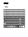
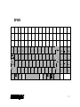
FRANCE
²
1
2
3
&
é
"
A
Z
4
# '
E
5
{ (
R
6
[ T
7
8
` _
¦ è
Y
U
9
\ ç
I
0
°
à @ )
O
+
] =
P
W
ñ
Ctrl
S
ÿ
D
X
Alt
F
C
G
V
H
B
J
N
K
?
,
L
£
.
;
M
/
:
Alt Gr
9
4
5
6
2
3
00
.
Entrée
%
µ
1
ù
*
Fin
§
ñ
!
ÿ
8
}
$
Q
7
Ctrl
0
Inser
Suppr
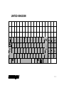
GERMANY
°
!
"
§
$
%
&
/
(
)
=
?
`
1
2
² 3
³ 4
5
6
7
{ 8
[ 9
] 0
} β
\ ´
Q
W
E
R
T
Z
U
I
O
P
U
@
ò
A
Y
ñ
Strg
S
ÿ
D
X
F
C
G
V
H
B
J
N
K
M
L
O
;
:
_
µ ,
.
-
Alt Gr
Alt
A
ÿ
7
8
Pos1
*
+
9
Bild
4
5
6
'
1
2
3
#
Ende
¦
ñ
0
Einfg
Bild
00
,
Entf
Strg
TM
2-3
TM
2-4
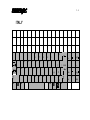
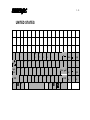
ITALY
¦
!
"
£
$
%
&
/
(
)
=
?
\
1
2
3
4
5
6
7
8
9
0
'
Q
W
E
R
T
Y
U
I
O
P
7
ì
Z
ñ
Ctrl
S
ÿ
D
X
Alt
F
C
G
V
H
B
J
N
K
M
L
°
§
ò @
à
# ù
:
_
,
.
-
Alt Gr
ÿ
4
5
6
1
2
3
] Invio
ç
;
9
Pag
*
[ +
é
è
A
8
Fine
ñ
Ctrl
0
Ins
Pag
00
.
Canc
NETHERLANDS
§
!
"
#
@
¬ 1
¹ 2
² 3
Q
W
$
_
(
)
'
?
³ 4 ¼ 5 ½ 6 ¾ 7
£ 8
{ 9
} 0
/
E
%
R
&
T
Y
U
I
O
7
\
P
A
D
Z
X
F
«
ÿ
C
»
G
V
¢
H
J
K
L
B
N
M
PgUp
4
5
6
2
3
±
`
1
+
´
End
;
:
=
[
µ ,
.
· -
]
Alt Gr
Alt
9
*
ß
ñ
Ctrl
S
Home
¦
¶
Caps
Lock
¸
°
8
ÿ
¦
ñ
0
Ins
PgDn
00
,
Del
Ctrl
TM
2-5
TM
2-6
PORTUGAL
¦
!
"
#
$
%
&
/
(
)
=
?
»
7
\
1
2 @
3
£ 4
§ 5
6
7
{ 8
[ 9
] 0
} '
«
Home
Q
Caps
Lock
A
ÿ
E
S
Z
ñ
Ctrl
W
D
X
Alt
R
T
F
C
Y
G
V
U
H
B
I
J
N
O
K
M
P
L
Ç
;
:
_
,
.
-
Alt Gr
ÿ
*
`
+
´
8
9
PgUp
4
5
6
ª
1
2
3
º
End
ñ
Ctrl
0
Ins
PgDn
00
.
Del
SPAIN
ª
"
·
$
%
&
/
(
)
=
?
¿
7
¦ 2 @
3
# 4
5
6
¬ 7
8
9
0
'
¡
Inicio
!
º \ 1
Q
W
E
R
T
Y
U
I
O
*
[ +
P
`
A
Bloq
Mayús
ÿ
D
F
G
H
J
K
L
Ñ
X
C
V
B
N
M
;
:
_
,
.
-
Alt Gr
Alt
ÿ
{
9
Re Pág
4
5
6
1
2
3
]
Ç
´
Z
ñ
Ctrl
S
8
}
Fin
ñ
0
Ins
Av Pág
00
.
Supr
Ctrl
TM
2-7
TM
2-8
SWEDEN/FINLAND
½
!
"
§
1
2 @ 3
Q
Caps
Lock
W
A
ÿ
£ 4
E
S
Z
ñ
Ctrl
#
R
D
X
Alt
$
%
&
/
(
)
=
?
`
5
6
7
{ 8
[ 9
] 0
} +
\ ´
T
F
C
Y
G
V
U
H
B
I
J
N
O
K
M
O
A
;
:
_
,
.
-
Alt Gr
ÿ
8
Home
Å
P
L
7
9
PgUp
4
5
6
*
1
2
3
'
End
¦
Ctrl
ñ
0
Ins
PgDn
00
,
Del
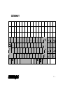
UNITED KINGDOM
¬
!
"
£
$
%
`
1
2
3
4
5
Q
Caps
Lock
A
E
S
Z
ñ
Ctrl
W
R
D
X
T
F
C
6
Y
G
V
&
*
(
)
_
+
7
7
8
9
0
-
=
Home
U
H
B
I
J
N
O
K
L
}
[
]
@
;
'
.
Alt Gr
Alt
{
:
M
,
ÿ
P
ÿ
#
?
¦
/
\
8
PgUp
4
5
6
1
2
3
End
ñ
9
0
Ins
PgDn
00
.
Del
Ctrl
TM
2-9
TM
2 - 10
UNITED STATES
`
Tab
!
@
#
$
%
1
2
3
4
5
Q
Caps
Lock
A
E
S
Z
ñ Shift
Ctrl
W
R
D
X
T
F
C
6
Y
G
V
&
*
(
)
_
+
7
7
8
9
0
-
=
Home
U
H
B
I
J
N
O
K
L
Alt
{
}
¦
[
]
\
:
"
;
'
M
Enter
?
,
ÿ
P
.
Alt
ñShift
/
ÿ
Ctrl
8
9
PgUp
4
5
6
1
2
3
End
0
Ins
PgDn
00
.
Del
TM
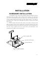
INSTALLATION
HARDWARE INSTALLATION
To install KB136 into a PST system originally equipped with KB112, the user
should disassemble the KB112 from the PST system according to the instructions
given in the Technical Manual of respective PST system. After this disassembly, there
are three cables coming from the inside of the PST system, namely, a 2 pin cable for
the standby LED, a 4 pin cable for KB signal and a DIN 5 pin cable for the external
KB connector.
The user shall connect these three cables to the proper connectors in the
KB136 assembly as shown in the example below. Unlock the mechanical lock, place
the programmable keyboard down and back to the position, lock the mechanical lock
and screw on the 2 bottom screws as in reverse order of the disassembly of the
keyboard unit. The KB136 is then well installed.
Cable for standby LED
4 pin cable for KB signal
External KB cable
Fig. 3 – 1 Cable connection
3-1
TM
UTILITY INSTALLATION
There are in total three methods to program the programmable keys in KB136
QWERTY keyboard: “RWM.EXE” the straightforward direct read/write
programming utility; “KBM.EXE” the normal programming utility and the “Hot Key
Programming” most suitable to modify the key contents of one or two keys.
Installation procedures are required for utilities “KBM.EXE” and “RWM.EXE”.
In the utility diskette, there is a file named “INSTALL.EXE” for installation of
all the utilities into any operating system among Windows95 Windows 3.1 and DOS.
The user may install the programming utility by following the step by step
instructions from this executable program. The user may refer to the information on
our web site for a preview of this program.
3-2
TM
PROGRAMMING
HOT KEY PROGRAMMING
The KB136 programmable keyboard supports the “hot key programming”
method which is most useful in instant modification of a few keys in a
preprogrammed keyboard without entering the more sophisticated programming
utility. Of course, the user may also use this feature to program through out all 51
keys (3 rows, 17 columns) by 5 pages (LP and L1 to L4) at will. The whole process of
“hot key programming” contains 4 steps for each key to be programmed and is
illustrated as following:
Preparation
Enter “hot key
programming”
mode
Input the
content to be
programmed
Exit “hot key
programming”
mode
PREPARATION
To enable “hot key programming” feature of the KB136 “QWERTY”
keyboard, a standard PC or PS-2 keyboard must be connected to the external KB
connector of KB136 before entering “hot key programming” mode. The user shall
then decide which key of which page is to be programmed and turn the 6 position
control key to the proper position before entering the “hot key programming” mode.
Please note that the answer back codes of the position control key and the 2
programmable keys in the numerical keypad are not covered by the “hot key
programming” feature.
ENTER “HOT KEY PROGRAMMING”
MODE
To enter the “hot key programming” mode, the user must input the “hot key”
and identify the key on the programmable keyboard to be programmed. The so-called
“hot key” is a special combination of keys pressed on the standard PC or PS-2
keyboard. In KB136, the “hot key” is defined as pressing and holding the left “Alt”
4-1
TM
key while pressing the “PRT SC” (“Print Screen”) key on the PC or PS-2 keyboard.
And by doing so, the KB136 will give 2 beeps to notify that it is ready to receive the
identification of which key to be programmed. Right after the “hot key” is released,
the user shall press the key to be programmed on the programmable keyboard once to
identify which key to be programmed. If the “hot key” is pressed for the second time
or the “esc” key is pressed prior to the press of the key on the programmable
keyboard, this mode will be aborted immediately. The user should not enter the “hot
key programming” mode when the programmable keyboard is already fully loaded
(no more free memory for further programming) by the key contents previously
programmed.
INPUT
THE
CONTENT
PROGRAMMED
TO
BE
Once the programmable keyboard enters the “hot key programming” mode
with the key to be programmed identified, what the user types on the standard PC or
PS-2 keyboard will be taken for the content to be programmed into that key of the
programmable keyboard till the user exits the “hot key programming” mode.
The legal input in this mode includes all alphabetical letters (including both
upper and lower cases), numerical digits (applicable only for keys at the area above
the alphabetical keys and excluding those on the numerical keypad), symbols (such as
`!”#$ and excluding those arithmetic signs in the numerical keypad) and the “enter”
key. The “shift” key, the “caps lock” key and the “back space” key are also accepted
in this mode to serve an editing purpose (for example, pressing “back space” will
erase the last character of the input instead of being treated as a character for input).
Pressing the “esc” key in this mode will abort the “hot key programming” mode
immediately. All the rest keys (such as the “Ctrl”, “Alt”, “Home”, any function key or
arrow key or any key in the numerical keypad) on the standard PC or PS-2 keyboard
are illegal inputs in this mode. The maximum number of key presses acceptable to any
key by “hot key programming” is 32.
All the input from the standard PC or PS-2 keyboard in this mode will also be
sent to the host computer. Any key press from the predefined or programmed KB136
for data input in “hot key programming” is prohibited.
4-2
TM
EXIT “HOT
MODE
KEY
PROGRAMMING”
After the intended content of the key is completely entered, the user shall press
the “hot key” again to notify the end of “hot key programming”. The programmable
keyboard will give one beep to signify the normal exit of the “hot key programming”
mode. Should there be any illegal entry in the content of the key or any other
improper operation during the programming, the programmable keyboard will give
three beeps to signify the failure of “hot key programming” and the key content is not
changed. If the user pressed the “esc” key to abort “hot key programming”, the
programmable keyboard will also give three beeps immediately as a response to
signify the abort.
4-3
TM
PROGRAMMING UTILITY (KBM.EXE)
GENERAL
Using the “KBM” utility for KB136 is quite similar to the way to use the
“KBM” utility for KB112 though they may be of different versions and should be
used distinctively. However, the screen display for KB136 is different from that for
KB112 as the physical layout is different. Therefore, the screen display is explained as
the following, whilst the user may refer to the relevant Technical Manual of PST
systems or the web site for the rest.
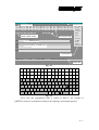
An illustration of each part of the screen display for programming this
keyboard is in Fig. 4-1, each area of the screen is labeled with its function. The user
may start programming right away with the arrow keys to move around in the key
layout map to select the key or the position control key to edit the content. The user
may also use the “PgUp” / “PgDn” key to select for different page (total 5 pages).
As demonstrated in example Fig. 4-2, the actual key layout of KB136 is
composed of 3 rows by 17 columns matrix of programmable keys (white area) at the
top and a “qwerty” portion plus numerical keypad (shaded area) with two
programmable keys at the bottom. The programming utility can in principle define the
white area indicated in Fig. 4-2 and the answer back codes of the 6 position control
key. The key definitions for the 3 by 17 matrix part can be altered according to the
Therefor, position of the 6 position key while the lower part (including the two
programmable keys and a reserved key) keeps unique definition for each key.
Please note in Fig. 4-2 that all programmable keys are put in parentheses even
the reserved possibility “RES”, which is in the shaded area indicating that this key is
in general non-accessible for normal use. Please also note that the keys 1A1 ~ 1Q3
shall be defined as 2A1 ~ 2Q3 or 3A1 ~ 3Q3 etc. if the 6 position key is turned to
position L2, L3 etc.. The font color of any programmed key in the key-layout map
will be changed into light blue on the screen for identification (though not
distinguishable on this manual as it is printed in black and white).
4-4
TM
Posiflex Programmable Keyboard Utility
vx.xx.xx
Program ID
Cursor position
1A1 1B1 1C1 1D1 1E1 1F1 1G1 1H1 1I1 1J1 1K1 1L1 1M1 1N1 1O1 1P1 1Q1
1A2 1B2 1C2 1D2 1E2 1F2 1G2 1H2 1I2 1J2 1K2 1L2 1M2 1N2 1O2 1P2 1Q2
1A3 1B3 1C3 1D3 1E3 1F3 1G3 1H3 1I3 1J3 1K3 1L3 1M3 1N3 1O3 1P3 1Q3
KLP KL0 KL1 KL2 KL3 KL4
F1: Help
PgUp
PgDn
Arrows
DEL
TOT SbT RES
Answer back codes
Key-layout map
ALT
+
27=Esc
8=BS
eXit
Delay
Separator
Editing area
1A1 _
1A1
1A2
1A3
Key-contents area
KLP
Command list
Page: L1/6
INS
ALT-X: EXIT
ASCII-CODE Editing
Status bar
Fig. 4-1
(1A1) (1B1) (1C1) (1D1) (1E1) (1F1) (1G1) (1H1) (1I1)
(1J1) (1K1) (1L1) (1M1) (1N1) (1O1) (1P1) (1Q1)
(1A2) (1B2) (1C2) (1D2) (1E2) (1F2) (1G2) (1H2) (1I2)
(1J2) (1K2) (1L2) (1M2) (1N2) (1O2) (1P2) (1Q2)
(1A3) (1B3) (1C3) (1D3) (1E3) (1F3) (1G3) (1H3) (1I3)
(1J3) (1K3) (1L3) (1M3) (1N3) (1O3) (1P3) (1Q3)
~
`
Tab
!
1
|
@
2
Q
W
$
4
E
%
5
R
^
6
T
*
8
&
7
Y
U
(
9
I
)
0
O
_
P
A
S
Z
ñ Shift
ÿ
D
X
Alt
F
C
G
V
H
B
J
N
K
M
:
;
L
<
,
(RES)
>
.
Alt
+
=
{
[
|
Caps
Lock
Ctrl
#
3
¦
\
}
]
"
'
Enter
?
/
ÿ
ñShift
Ctrl
7
8
Home
9
PgUp
4
5
6
1
End
2
3
PgDn
0
Ins
00
.
Del
(SbT) (TOT)
Fig. 4-2
Every time the programmed data is written to KB136, the content of
QWERTY portion is refreshed according to the language environment applied.
4-5
TM
COMMAND LISTING IN VIEW MODE
ESC – quit the keyboard programming program
F1 – get help on command list
F3 – enter the configuration screen
F5 – enter ASCII-code editing mode
F8 – enter scan-code editing mode
F10 – quit the keyboard programming program
Ins – toggle insert/overwrite status for editing (default = insert)
Del – delete the content of the key where cursor stays
Home – go to column A of same page same row
End – go to column I of same page same row
PgUp – go to one page less in cyclic manner
PgDn – go to one page next in cyclic manner
Up arrow – move cursor to one row up in cyclic manner
Down arrow – move cursor to one row down in cyclic manner
Left arrow – move cursor to one column left in cyclic manner
Right arrow – move cursor to one column right in cyclic manner
ENTER – enter ASCII-code editing mode, but if the last edit of the key was in scancode mode then this means enter scan-code editing mode.
Alt-A – enter ASCII-code editing mode
Alt-C – copy the key content of a key or contents of the keys in a page to buffer
Alt-E – erase the current page or all pages
Alt-G – enter the configuration page
Alt-L – load key definitions from a disk file
Alt-M – enter multi-level shift marker
Alt-N – enter scan-code editing mode
Alt-O – load key definitions from a disk file
Alt-P – paste the buffer content to key definition
Alt-R – read key definitions from the programmable keyboard
Alt-S – save key definitions to a disk file
Alt-T – toggle key-content format between page-wise and column-wise
Alt-U – recover key definition before last change
4-6
TM
Alt-W – write key definitions to the programmable keyboard
Alt-X – quit the keyboard programming program
any other key stoke – will be taken as an input in ASCII-code editing mode, and will
give no influence if the current key was last edited in scancode editing mode
COMMAND LISTING
EDITING MODE
IN
ASCII-CODE
ESC – enter view mode
F1 – get help on command list of ASCII- code editing mode
F5 – enter view mode
F8 – enter view mode
F10 – enter view mode
BkSp – delete the character to the left of cursor
Ins – toggle insert/overwrite status for editing (default = insert)
Del – delete the character where cursor stays or the last character
Home – go to first position within the key definition
End – go to last position within the key definition
PgUp – go to one page less in cyclic manner
PgDn – go to one page next in cyclic manner
Up arrow – move cursor to one row up in cyclic manner and enter view mode
Down arrow – move cursor to one row down in cyclic manner and enter view mode
Left arrow – move cursor to one character left within the key definition
Right arrow – move cursor to one character right within the key definition
Alt-A – enter view mode
Alt-D – enter time delay mark into the key-content
Alt-N – enter view mode
Alt-S – enter a multi-level separator between definitions of different levels.
Alt-X – enter view mode
Alt-27 – enter an “ESC” into the key-content
Alt-8 – enter a “BkSp” into the key-content
Ctl-C – immediately terminates the programming utility.
4-7
TM
any other key stoke – will be taken as an input in ASCII-code editing mode.
COMMAND LISTING IN SCAN CODE
EDITING MODE
ESC – leading code to enter scan code of any key after it into key-content, except
“ESC” + “F” for utility version since 2.15.xx
ESC-F – leading code of arbitrary release code for utility version since 2.15.xx.
usually used to release “CTL”, “ALT” or “SHF”.
F1 – get help on command list of ASCII- code editing mode
F5 – enter view mode
F8 – enter view mode
F10 – enter view mode
BkSp – delete the character to the left of cursor
Ins – toggle insert/overwrite status for editing (default = insert)
Del – delete the character where cursor stays or the last character
Home – go to first position within the key definition
End – go to last position within the key definition
PgUp – go to one page less in cyclic manner
PgDn – go to one page next in cyclic manner
Up arrow – move cursor to one row up in cyclic manner and enter view mode
Down arrow – move cursor to one row down in cyclic manner and enter view mode
Left arrow – move cursor to one character left within the key definition
Right arrow – move cursor to one character right within the key definition
Alt-A – enter view mode
Alt-D – enter time delay mark into the key-content
Alt-M – enter a multi-level shift marker into the key-content
Alt-N – enter view mode
Alt-S – enter a multi-level separator between definitions of different levels.
Alt-X – enter view mode
Alt-27 – work like “ESC” as the leading code for scan codes.
Alt-8 – enter a “BkSp” into the key-content
Ctl-C – immediately terminates the programming utility.
4-8
TM
any other displayable key stoke – will be taken as an input in scan-code format.
any other non-displayable key stroke – will have no influence
ANSWER BACK CODE
Programming the answer back codes of the 6 position electronic key-lock is
also very easy as they are included in the keyboard programming with the locations
coded as “KLP”, “KL0”, “KL1”, “KL2”, “KL3” and “KL4” in the key-layout map of
page L1. The programmable keyboard will issue an answer back code to PC whenever
the 6 position electronic key is switched to a new position or when the keyboard
receives an “enquiry” code (E7h) from the PC or the PST system. A time delay as
determined in the configuration of the keyboard programming utility is adjustable by
“r” and “t” key presses, this time delay is useful to give only the answer back code of
the last position of control key when it is turned across several positions. Here are
some examples of sending this “enquiry” code in different languages:
Language
Syntax
C
outp (0x60, 0xE7)
BASIC
out &H60, &H0E7
DEBUG
o 60 E7
HARDWARE LIMITATION
In case of “multiple combination key” application which means pressing three
or more keys at the same time to obtain certain data output from the keyboard, there
could be some limitations inherent from the nature of keyboard structure. The CPU of
keyboard detects the contact between the “horizontal” and “vertical” lines for each
key press, recognizes which key is pressed and sends correspondent data to the host
computer. When there are many keys pressed at the same time, and the pattern of the
contacts coincides with some special relationship, there are chances that the CPU of
keyboard be confused about exactly which keys are pressed. The user may change the
locations of the key-definition to prevent this once such confusion happens.
4-9
TM
SHORTCUT UTILITY (RWM.EXE)
The feature of this RWM.EXE is designed mainly for the off-line
programming purpose and is very useful in quick reproduction of the preprogrammed
contents of the programmable keyboard. In such application, the user should have
either the preprogrammed keyboard or the preprogrammed file with “.tpl” extension
name which is the result of the keyboard programming. The user may use RWM.EXE
to directly transfer the programmed result of the programmable keyboard to a “.tpl”
file or directly transfer a prestored “.tpl” file to a programmable keyboard without
entering the utility “KBM.EXE” which may take more keystrokes. For instance, the
user wants to transfer a file “XXX.tpl”, which was saved before, to the programmable
keyboard, he/she should type in following command in subdirectory “POSIFLEX.D”:
RWM XXX.tpl
(enter)
This operation is quite recommended to be performed on a daily basis to
ensure the system stability.
On the other hand, when the user wants to save the contents of a programmed
keyboard, e.g. when he/she newly receives a programmable keyboard, to a file named
“YYY.tpl”, he/she should type in following command in subdirectory
“POSIFLEX.D”:
RWM –r YYY.tpl
(enter)
In this application, the user must be careful on the housekeeping of these
template files and never mix such files with those originated from other
programmable keyboard. In other words, transferring a file generated from other
programmable keyboard to KB136 could mess up the data format inside KB136, and
vice versa.
4 - 10
TM
DETAILS IN PROGRAMMING
Please refer to our web site for every detail in programming this KB136. The
following simplified guide severs as a concise tool for instant application.
QUICK KEYBOARD PROGRAMMING REFERENCE GUIDE
Keys To Program
How to Program Them
Esc, F1 - F12, Back Space, Shift, Ctrl,
Alt, Insert, Delete, End, Page Up,
Press: (Alt-N), Esc, "Desired Key", Down
Page Down, Print Scrn, Scroll Lock,
Arrow
Break, and all Arrow Functions
A - Z, 0 - 9, ~ ` ! @ # $ % ^ & * ( ) - _ Press: Enter, "Desired Key or Keys", Down
= + } { [ ] | \ ' ; " : /. , < > ?
Arrow
Tab, Enter
Press: (Alt-N), "Desired Key", Down Arrow
Caps Lock
Press: Enter, (Alt-C), Down Arrow
Multishift
Press: (Alt-N), (Alt-M), Down Arrow - - - Press (Alt-M) as many times as needed.
Seperator
In Between Any Text, Press (Alt-S)
Different Levels
Press: Page Up or Page Down - - - - You'll
see an indicator on the bottom left,
corresponding to what level you are on.
5-1
TM
5-2
TM
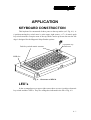
APPLICATION
KEYBOARD CONSTRUCTION
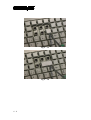
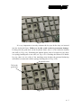
This keyboard is constructed of three parts on the top surface (ref. Fig. 6-1). A
6 position turning key switch area is at the upper right corner, a 17 x 8 matrix push
key switch structure occupies most of the top surface and a up-down slot near the left
edge is designed for the Magnetic Stripe Reader options.
Push key switch matrix structure
6 position key
switch area
MSR slot
Fig. 6 – 1 Structure of KB136
LED’s
In the rectangular area at upper right corner there are one 6 position electronic
key switch and three LED’s. They are arranged as indicated in the left of Fig. 6-2.
6-1
TM
L2
L1
L3
L2
L4
LP
Stand-By
L1
L3
L4
LP
POWER
Stand-By
POWER
Caps Lock
Num.Lock
Caps Lock
Fig. 6 – 2 Layout in 6 position key switch area
The top left LED is for stand-by indication, the top right LED is the power-on
indicator and the bottom right LED is the Cap-Lock indicator for the “QWERTY”
keyboard. For the KB136 manufactured after year 1999, another LED at the bottom
left is added to indicate Num-Lock status of the numerical keypad as shown in the
right in Fig. 6-2.
The two top LED’s work exactly in the way the host system (e.g. PST1000 or
PST6000 series) defines. In other words, the description in the user’s manual of the
system applies for these two LED’s.
For the “Caps Lock” or “Num Lock” LED at the bottom, the function as of a
normal standard PC or PS/2 keyboard applies if the KB136 is operating alone without
an external PC or PS/2 keyboard connected. When an external PC or PS/2 keyboard is
connected, pressing the “Caps Lock” key or the “Num Lock” key on the PC or PS/2
keyboard will have both the correspondent LED on KB136 and PC or PS/2 keyboard
change status accordingly. Yet, if it is the “Caps Lock” key or the “Num Lock” key
on KB136 pressed, only the correspondent LED on KB136 will change while the
LED on PC or PS/2 keyboard remain unchanged.
6 POSITION KEY-LOCK
The 6 position electronic key-lock in KB136 is identical to the one in KB112.
Please refer to the PST system manuals.
6-2
TM
PUSH KEY SWITCH MATRIX
The major part on the keyboard surface is constructed in a 17 x 8 matrix
providing a possibility of maximum 136 key positions available. This is why this
keyboard is named as KB136. However, as indicated before, while the upper 17 x 3
matrix remains in matrix and page dependent, the lower part is organized in
“QWERTY” format. This “QWERTY” format portion, occupying an area of 5 whole
rows and containing two programmable keys, is country dependent and page
independent and never possesses as many as 85 keys for any country as the layout
dictates. So there will never be a total number of actually 136 keys for any country
throughout the KB136 series.
The numerical keypad portion will function as arrow keys and “Home”,
“End”, “Ins” etc. like the numerical keypad on a standard PC or PS/2 keyboard does if
the “Num Lock” status is OFF.
The marking on the “QWERTY” keys and the numerical keys is non-erasable.
To mark the programmed keys, please refer to the method explained for KB112.
KEY TOP REPLACEMENT
In the push key switch matrix area, there are 17 by 3 programmable keys. Yet,
there are chances that the user may want to compromise some number of
programmable keys for a larger key for ease of operation. In such occasions, the user
may purchase the double key option, remove the single keys and insert the double key
and sometimes remove the double key for other arrangement. The user may use a flat
bladed screwdriver to remove the key tops (ref. Fig. 6-3a, b & c). Please note that
there are two possible directions for a double key.
6-3
TM
Fig. 6 – 3a
Fig. 6 – 3b
6-4
TM
Fig. 6 – 3c
It is very important to correctly orientate the key tops before they are inserted
into the keyboard frame. Failure to do this could result in permanent damage.
Looking into the guide hole on the keyboard frame, there is a tab inside the bottom
side wall (ref. Fig. 6-4). Examining the bottom square stem of a single key top, there
is a springy latching tab on one side (ref. Fig. 6-5a). Checking the bottom of a double
key top, there are two sides of the matching stem (besides the patented balancing
mechanism) constructed with the springy latching tab (ref. Fig. 6-5b).
Keyboard frame
Tab in the
guide hole
Fig. 6 – 4
6-5
TM
Key top
Double key top
Latching tab
Latching tab
Latching tab
Fig. 6 – 5a
Fig. 6 – 5b
When any key top is to be inserted onto the keyboard frame, the tab on the
inside wall of the key top guide hole must mate a corresponding springy latching tab
as illustrated above. In this way, the matching stem of a double key must be either at
the bottom when the double key is “vertically” aligned or at the right of the key
coverage area when the double key is “horizontally” aligned. The location for the keydefinition to be programmed for the double key shall then be the bottom or the right
position accordingly.
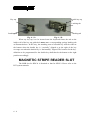
MAGNETIC STRIPE READER SLOT
The MSR slot for KB136 is identical to that for KB112. Please refer to the
PST system manuals.
6-6
TM
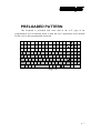
PRELOADED PATTERN
This keyboard is preloaded with some data in the “LP” page of the
programmable area as indicated below to help the user’s application at the moment
he/she receives this programmable keyboard.
Insert Home PgUp
Esc
F1
F2
F3
F4
F5
F6
F7
F8
Delete End
PgDn
F9
F11
F10
F12
Print
Scroll Pause Num
Lock
Screen Lock
~
`
Tab
!
1
|
@
2
Q
W
$
4
E
%
5
R
^
6
T
*
8
&
7
Y
U
(
9
I
)
0
O
_
P
A
S
Z
ñ Shift
ÿ
D
X
Alt
F
C
G
V
H
B
J
N
K
M
:
;
L
<
,
>
.
Alt
+
=
{
[
|
Caps
Lock
Ctrl
#
3
¦
\
}
]
"
'
Enter
?
/
ÿ
ñShift
7
8
Home
9
PgUp
4
5
6
1
End
2
3
PgDn
0
Ins
00
.
Del
Ctrl
Fig. 6 – 6
6-7
TM
6-8
TM
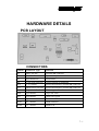
HARDWARE DETAILS
PCB LAYOUT
CONNECTORS
Position
Connector Type
Function
JP1
DIP 5 pin jack
External KB connector
JP3
8 x 1 header
6 position key lock
JP5
4 pin header 90°
Internal KB
JP6
11 pin lock connector
Narrow tongue of membrane
JP12
(7 x 1 header)
Reserved alternative external KB connector
JP13
(Mini DIN 6 pin jack)
Reserved alternative external KB connector
JP15
16 pin lock connector
Wide tongue of membrane
JP20
2 pin header
Cap Lock LED
JP21
2 pin header
(Num Lock LED)
JP181
2 pin header
Power On LED
JP185
8 x 1 header
MSR connector
JP186
3 x 1 header
MSR LED
7-1
TM
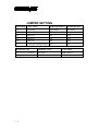
JUMPER SETTING
POSITION FUNCTION
JUMPER SHORT JUMPER OPEN
J10
JIS II/ISO
JIS II MSR
ISO MSR
J13
ALT + NUM
OFF
ON
J14
TRACK 1
ON
OFF
J15
TRACK 3
ON
OFF
J16
TRACK 2
ON
OFF
J17
Leading & ending sentinel OFF
ON
JP183 STATUS
JP184 STATUS
FUNCTION
1-2, 3-4, 5-6, 7-8 short
All open
MSR enabled
All open
1-2, 3-4 short
MSR disabled
7-2
TM
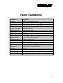
PART NUMBERS
Part Number
Description
PSTKB136
Stroke type keyboard w/o MSR
PSTKB136MR2
Stroke type keyboard with 2 track MSR
PSTKB136MR3
Stroke type keyboard with 3 track MSR
PSTKB136MRJS2
Stroke type keyboard with JIS II MSR
PSTKB136CPUMR
Keyboard controller
CMSRCATRIGE-2
MSR module 2 tracks
CMSRCATRIGE-3
MSR module 3 tracks
CMSRCATRIGE-4A
MSR module JIS II
PSTKBELCK6PASY
6 position key lock with wafer assembly
PSTKB112EKEY
4 key set for 6 position key lock
PSTKBMECHKEY
Keyboard front door key
PSTKBDR-1
Keyboard front door
CCBLA-151
Power / Caps Lock LED, (green) with cable
CCBLA-152
MSR LED, (dual color) with cable
CCBLA-167-2
Stand by LED, (yellow) with cable
QCH-2000
Key clip
CLABKBPSTHKB112 Legend sheet for qwerty keyboard in 4 colors
PSTHKEYPAIR
1 x 1 single key top & key cap pair
PSTHDBKEYPAIR
1 x 2 double key top & key cap pair
8-1
TM
8-2