1
KP-300
SIDE MOUNT
PROGRAMMABLE KEYPAD
USER’S MANUAL
Rev.: A0
FCC Notes:
This equipment generates, uses, and can radiate radio frequency energy and, if not
installed and used in accordance with the instructions manual, may cause interference
to radio communications. It has been tested and found to comply with limits for a Class
A digital device pursuant to subpart J of Part 15 of FCC Rules, which are designed to
provide reasonable protection against interference when operated in a commercial
environment. Operation of this equipment in a residential area is likely to cause
interference in which case the user at his own expense will be required to take whatever
measures to correct the interference.
Warranty Limits:
Warranty terminates automatically when any person other than the authorized
technicians opens the machine. The user should consult his/her dealer for the problem
happened. Warranty voids if the user does not follow the instructions in application of
this merchandise. The manufacturer is by no means responsible for any damage or
hazard caused by improper application.
About This Manual:
Posiflex Technologies, Inc. has made every effort for the accuracy of the content in this
manual. However, Posiflex Technologies, Inc. will assume no liability for any technical
inaccuracies or editorial or other errors or omissions contained herein, nor for direct,
indirect, incidental, consequential or otherwise damages, including without limitation
loss of data or profits, resulting from furnishing, performance, or use of this material.
This information is provided “as is” and Posiflex Technologies, Inc. expressly
disclaims any warranties, expressed, implied or statutory, including without limitation
implied warranties of merchantability or fitness for particular purpose, good title and
against infringement.
The information in this manual contains only essential hardware concerns for general
user and is subject to change without notice. Posiflex reserves the right to alter product
designs, layouts or drivers without notification. The system integrator shall provide
applicative notices and arrangement for special options utilizing this product. The user
may find the most up to date information of the hardware from web sites:
http://www.posiflex.com or http://www.posiflex.com.tw or http://www.posiflexusa.com
All data should be backed-up prior to the installation of any drive unit or storage
peripheral. Posiflex Technologies, Inc. will not be responsible for any loss of data
resulting from the use, disuse or misuse of this or any other Posiflex product.
All rights are strictly reserved. No part of this documentation may be reproduced,
stored in a retrieval system, or transmitted in any form or by any means, electronic,
mechanical, photocopying, or otherwise, without prior express written consent from
Posiflex Inc. the publisher of this documentation.
© Copyright Posiflex Technologies, Inc. 2007
All brand and product names and trademarks are the property of their respective holders.
Part 1
P/N: 19830900020
GENERAL DESCRIPTION
OVERVIEW
Table below indicates construction of this series of security devices.
Model
KP-300
Structure
Upgrade kit for KS series
Programmable keypad
Vertical layout
Magnetic stripe reader
Optional
Smart card reader
Optional
OPTIONS
Items underlined below means that this item must be installed by Posiflex
authorized distributor only and never by average user. Items in Italic printing
below means that this item must be installed prior to delivery from the factory.
• Magnetic Stripe Reader (USB interface)
∗ ISO 7811 reader head for tracks 1 and 2
∗ ISO 7811 reader head for tracks 1, 2 and 3 + AAMVA + CA DMV
∗ JIS/II reader head
• Smart card reader
• Sound ports
• Case color selection between ivory and black
Part 2
INSTALLATION GUIDE
UNPACKING CONTENTS
Items packed in for
Qt’y
The side mount programmable keypad itself
1
Posiflex product information CD
1
Transparent key caps for single key
20
Key clip
1
Control keys (4 pcs / set)
1
Legend sheets (4 sh. / set)
1
This manual
1
Note: Utility drivers for KP-300 can be found in the CD ROM packaged or
please find for latest updates by visiting driver download page of our web
site:http://www.posiflex.com.tw/DriversDownload.asp
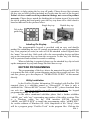
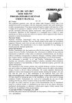
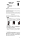
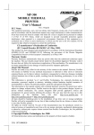
MECHANICAL FIXATION
For the KP-300 to be installed in the KS
series host system, the upgrade kit is installed to the
right edge of the LCD panel. You may find two
screw holes on back of the right side of the main
unit of KS series as circled in the left picture.
Remove these 2 screws to remove the cover for side
mount upgrade kit as arrowed in same picture. Take out the cable
inside this cover as circled in upper right picture and then
connect it to connector inside the side mount upgrade kit KP300
as arrowed in same picture. Gently arrange the excessive length
of this cable back in the hole and use the 2 original screws to fit
KP-300 back to the position originally occupied by the cover as
in the lower right picture. Please reserve the cover if there is
chance to have the side mount kit removed in the future.
KEYTOP LAYOUT
Keytop Replacement
The keypad in KP-300 is organized into 2 parts: a 4 by 4 numerical
keypad area and a 4 by 6 matrix minus a 2 by 2 square recess programmable
keypad area. However, this keypad allows some layout alterations by the
system integrator. Besides the standard single key installed, there are double
keys and blank keys for purchase to provide more convenient user interface.
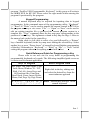
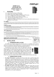
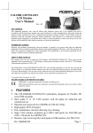
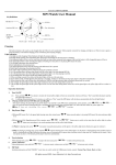
When replacement of keytop is required, it is advisable to use a
flattop (minus sign) screw driver (Do not use the attached key clip for this
Part 3
operation.) to help getting the key top off gently. Please always first orientate
the key tops as below before inserting any keytop into the case of the keypad.
Failure to do so could result in permanent damage not covered in product
warranty. Please always match the latching tab on bottom stem of keytop with
the tab in guiding hole and gently press the key top down till a click sound is
heard as indicated in the pictures below.
Single key top
Double key top
Tab in the
guide hole
Latching tab
Labeling On Keytop
The programmable keypad is provided with an easy and durable
method for reminding the user of content programmed in each programmable
key. First preprint (or write) in each cell of the attached colored legend sheet
the “name” for each key. Stick each cell to the corresponding keytop and then
put on the transparent key cap from the accessories. In this way, the labeling
will be protected and resistant to scratch or rubbing.
When re-labeling is required, please use the attached key clip to hook
up the transparent key cap and change the label then re-cap.
KEYPAD PROGRAMMING
The programming of the keys above the numerical keypad in KP-300
is in general the task of the system integrator and not the average end user. For
end user, please go to the chapter of “OPERATION GUIDE” of this manual
directly.
Utility Installation
In the Posiflex Product Information CD attached with Posiflex POS
terminal, there is a subfolder named as “\Drivers\KP”. If there is only a
subfolder like “\Drivers\KP100” but not “\Drivers\KP”, please download from
our web site: http://www.posiflex.com.tw/DriversDownload.asp the keypad
programming utility for KP-300.
In the above mentioned subfolder please find a further subfolder
“uKBW_xxx” with “xxx” representing any number of the utility revision. This
is a Windows utility for the USB interface KP-300. Execute
“uKBW_xxx\SETUP.EXE” to install the programming utility “uKBW.EXE”
for various editions of Windows OS. After completion of the “Setup”, there
will be a program group “Posiflex Tools” in the program files. Clicking the
Part 4
program “Posiflex USB Programmable Keyboard” in this group will activate
the uKBW.EXE for KP-300. Please select the right model when entering the
program if questioned by the program.
Keypad Programming
A normal keyboard may be required for inputting data in keypad
programming. In the command menu of the programming utility, “Keyboard”
=> “Read” or “Write” can be used to transfer the current content in KP-300 to
the program memory or vice versa. “File” => “Open” or “Save” can be used to
edit an existing template file or preserved the current program content to a
template file. “View” command alters the key map page corresponding to the
position of control key. The rightmost column in key map for Page 1 refers to
the answer back codes for the control key.
Right click (or left click to select a key and followed by a “Return”
key of normal keyboard) in the key map starts editing the selected key. Select
another key or press “Down Arrow” of normal keyboard finishes programming
of that key. Remember to “Keyboard” => “Write” or “File” => “Save” before
exiting the program otherwise everything worked will be lost.
Quick Reference Guide for Programming a Key
Please refer to our web site for every detail in programming the
programmable keyboards or keypads. The following simplified guide severs as
a concise tool for instant application.
Keys To Program
How to Program Them
Esc, Enter, Tab, Back Space, Caps
Lock, Menu, Window, F1 - F12,
Shift, Ctrl, Alt, Arrow Keys and
All Functions like: Print Scrn,
Scroll Lock, Pause, Insert, Delete,
Home, End, Page Up, Page Down
Right click in the key editing area
and select the desired key from the
menu/submenu appeared
A - Z, 0 - 9, ~ ` ! @ # $ % ^ & * ( ) Press: “Desired Key or Keys” of the
- _ = + } { [ ] | \ ’ ; ” : /. , < > ?
normal keyboard
Part 5
Hardware Limitation in Programming
In case of “multiple combination key” application which means
pressing three or more keys at the same time to obtain certain data output from
the keypad, there could be some limitations inherent from the nature of keypad
structure. The CPU of keypad detects the contact between the “horizontal” and
“vertical” lines for each key press, recognizes which key is pressed and sends
correspondent data to the host computer. When there are many keys pressed at
the same time, and the pattern of the contacts coincides with some special
relationship, there are chances that the CPU of keyboard be confused about
exactly which keys are pressed. The user may change the locations of the keydefinition to prevent this once such confusion happens.
MSR CONFIGURATION
Please find the subfolder “\Drivers\KP\USBMSR_xxx” in the
Posiflex Product Information CD or download from our web as mentioned
earlier and execute the “SETUP.EXE” to install the USB MSR manager under
Windows OS. The USB MSR manager can control parameters like individual
track enable/disable, Alt+Num emulation and Start/end sentinel substitute.
SMART CARD READER DRIVER INSTALLATION
Please find the subfolder “\Drivers\KP\SC200” in the Posiflex
Product Information CD or download from our web as mentioned earlier.
Execute the “SETUP.EXE” to install the driver into the Windows OS. The
reader is PC/SC 1.0 compliant. The reader is also EMV level 1 compliant. The
smart card reader is also supported by Microsoft CCID generic class driver.
Part 6
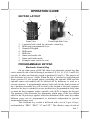
OPERATION GUIDE
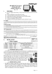
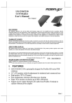
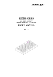
KEYPAD LAYOUT
1
7
6
2
4
3
5
8
1.
2.
3.
4.
5.
6.
7.
8.
Front Right Side View
Front View
6 position lock switch for electronic control key
Multi-page programmable keys
Numerical keypad
MSR mark
MSR slot
Smart card reader slot
Smart card reader mark
Example smart card to be read
PROGRAMMABLE KEYPAD
Electronic Control Key
On top right corner of KP-300, there is an electronic control key that
can be turned to one of the following 6 positions: LP, L0, L1, L2, L3 and L4. It
can only be taken out from the switch at positions L0 and L1. The purpose of
this electronic key serves 3 folds: When the key is switched to (and extracted
from) position L0, the keypad output (excluding the optional MSR and the
optional smart card reader) will be blocked off by hardware to work as a
security measure. A programmable answer back code for the final position of
the 6 position electronic key will be sent by the keypad to the host computer
whenever the key is switched to a new position for a programmable delay time
or when the host computer sends a specific code (E7h) to inquire the keypad.
The position of the electronic key determines which page of the key content
table for the 20 push keys applies, while the definitions of the same key within
different pages can be programmed so absolutely independent to provide
instant menu change over.
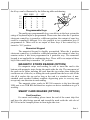
This electronic key switch is delivered with a set of 4 pcs of keys,
each marked as “PRG”, “REG”, “Z” and “GT”. The effective range of each of
Part 7
the 4 keys can be illustrated by the following table and drawing.
PRG REG
LP
L0
L1
L2
L3
L4
Y
Y
Y
Y
Y
N
N
Y
Y
Y
N
N
Z
GT
N
Y
Y
Y
Y
N
N
Y
Y
Y
Y
Y
Programmable Keys
The multi-page programmable keys can deliver to the host system the
string of keyboard input as programmed. Please note that when the 6 position
electronic control key is turned to a different position, the content of same key
could be completely different. It is also possible to use combination keys if
programmed to. There will be no output of these keys if the control key is
turned to “L0” position.
Numerical Keypad
The numerical keypad is durably pre-marked. When the 6 position
electronic control key is turned to a different position, the content of same key
remains unless it has been programmed in a particular way. The numerical
keypad is not applicable in combination keys. There will be no output of these
keys if the control key is turned to “L0” position.
MAGNETIC STRIPE READER (OPTION)
For magnetic stripe card reading, be sure to insert the card to the
bottom with magnetic stripe facing the mark aside the slot. The movement of
the card can be either inserting the card from the top surface then sliding the
card down out of the slot, or sliding the card upward from the lower side of the
slot till it reaches the top end as long as the card is a standard one. A nonstandard card recorded without complete degaussing prior to recovery may
accept only one direction in card reading.
The magnetic stripe reader in KP-300 connects to the host through
USB port as an USB KB and therefore requires no driver installation to get it
working.
SMART CARD READER (OPTION)
Card Insertion
For smart card reading, please insert the end of the smart chip first
and have the chip facing upward and toward the mark aside the side slot of
KP-300 as in the example picture in front right side view.
Part 8
Applicable Smart Card Type
The smart card reader can be used for both asynchronous and
synchronous type smart cards. For asynchronous type smart card, it reads the
card with T = 0 and T = 1 protocols up to 340 Kbps of EMV and ISO modes.
For synchronous type smart card, coverage includes: 2-wire (SLE4432/42), 3wire (SLE4418/28) etc., SDA/I2C, 4403, 4433, 4404, 896
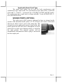
SOUND PORTS (OPTION)
The audio port in KS system is arranged to have an internal audio
speaker with maximum audio power of 2 W at lower left corner of the main
unit but no direct access port in the main unit. The
external access to audio ports can be found in the side
mount option kit KP-300 with a Microphone in and a
stereo line out jacks at its bottom surface as circled in
the right picture. The internal speaker will be
automatically disconnected when a plug is inserted in
the line output jack.
Part 9
警告使用者
T31454
這是甲類的資訊產品,在居住的環
境中使用時,可能會造成射頻干
擾,在這種情況下,使用者會被要
求採取某些適當的對策。
Part 10