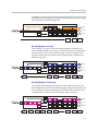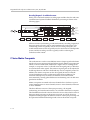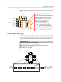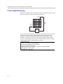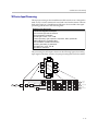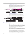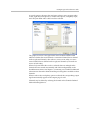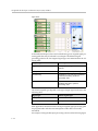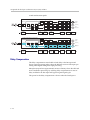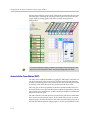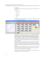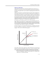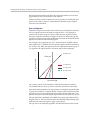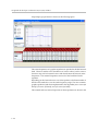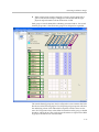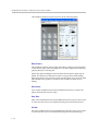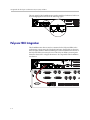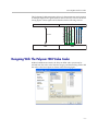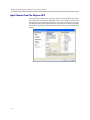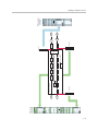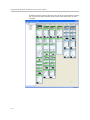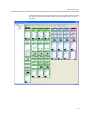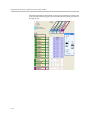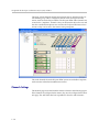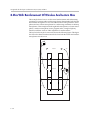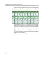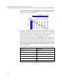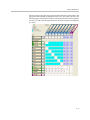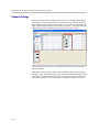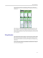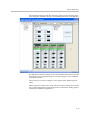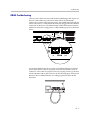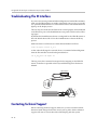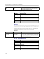
1
Design Guide
for the Polycom SoundStructure
C16, C12, C8, and SR12
3725-33186-001
Revision: B
Trademark Information
Polycom®, the Polycom logo design, and Vortex® are registered trademarks of Polycom, Inc., and Global Management
System™, MGC™, People+Content™, People On Content™, Polycom InstantDesigner™, Polycom PathNavigator™,
PowerCam™, Siren™, and VSX® are trademarks of Polycom, Inc. in the United States and various other countries.
VISCA is a trademark of Sony Corporation. All other trademarks are the property of their respective owners.
Patent Information
The accompanying product is protected by one or more U.S. and foreign patents and/or pending patent applications
held by Polycom, Inc.
Disclaimer
Some countries, states, or provinces do not allow the exclusion or limitation of implied warranties or the limitation of
incidental or consequential damages for certain products supplied to consumers, or the limitation of liability for personal
injury, so the above limitations and exclusions may be limited in their application to you. When the implied warranties
are not allowed to be excluded in their entirety, they will be limited to the duration of the applicable written warranty. This
warranty gives you specific legal rights which may vary depending on local law.
Copyright Notice
Permission is hereby granted, free of charge, to any person obtaining a copy of this software and associated
documentation files (the "Software"), to deal in the Software without restriction, including without limitation the rights to
use, copy, modify, merge, publish, distribute, sublicense, and/or sell copies of the Software, and to permit persons to
whom the Software is furnished to do so, subject to the following conditions:
The above copyright notice and this permission notice shall be included in all copies or substantial portions of the
Software.
THE SOFTWARE IS PROVIDED "AS IS", WITHOUT WARRANTY OF ANY KIND, EXPRESS OR IMPLIED,
INCLUDING BUT NOT LIMITED TO THE WARRANTIES OF MERCHANTABILITY, FITNESS FOR A PARTICULAR
PURPOSE AND NONINFRINGEMENT. IN NO EVENT SHALL THE AUTHORS OR COPYRIGHT HOLDERS BE
LIABLE FOR ANY CLAIM, DAMAGES OR OTHER LIABILITY, WHETHER IN AN ACTION OF CONTRACT, TORT OR
OTHERWISE, ARISING FROM, OUT OF OR IN CONNECTION WITH THE SOFTWARE OR THE USE OR OTHER
DEALINGS IN THE SOFTWARE.
© 2007 Polycom, Inc. All rights reserved.
Polycom Inc.
4750 Willow Road
Pleasanton, CA 94588-2708
USA
No part of this document may be reproduced or transmitted in any form or by any means, electronic or mechanical, for
any purpose, without the express written permission of Polycom, Inc. Under the law, reproducing includes translating
into another language or format.
As between the parties, Polycom, Inc. retains title to, and ownership of, all proprietary rights with respect to the software
contained within its products. The software is protected by United States copyright laws and international treaty
provision. Therefore, you must treat the software like any other copyrighted material (e.g. a book or sound recording).
Every effort has been made to ensure that the information in this manual is accurate. Polycom, Inc. is not responsible
for printing or clerical errors. Information in this document is subject to change without notice.
Contents:
1
Introduction . . . . . . . . . . . . . . . . . . . . . . . . . . . . . . . . . . . . . . . . . 1–1
2
SoundStructure Product Family . . . . . . . . . . . . . . . . . . . . . . . . . . . 2–1
SoundStructure Architecture Overview . . . . . . . . . . . . . . . . . . . . . . . . . . . . . . . . . 2–1
OBAM™ - One Big Audio Matrix . . . . . . . . . . . . . . . . . . . . . . . . . . . . . . . . . . . . . . 2–3
SoundStructure C-series Products . . . . . . . . . . . . . . . . . . . . . . . . . . . . . . . . . . . . . . 2–5
C-Series Input Processing . . . . . . . . . . . . . . . . . . . . . . . . . . . . . . . . . . . . . . . . . 2–7
C-Series Matrix Crosspoints . . . . . . . . . . . . . . . . . . . . . . . . . . . . . . . . . . . . . . 2–12
C-Series Output processing . . . . . . . . . . . . . . . . . . . . . . . . . . . . . . . . . . . . . . . 2–13
C-Series Submix Processing . . . . . . . . . . . . . . . . . . . . . . . . . . . . . . . . . . . . . . 2–14
C-Series Acoustic Echo Canceller References . . . . . . . . . . . . . . . . . . . . . . . . 2–15
SoundStructure SR-Series Products . . . . . . . . . . . . . . . . . . . . . . . . . . . . . . . . . . . . 2–16
SR-Series Input Processing . . . . . . . . . . . . . . . . . . . . . . . . . . . . . . . . . . . . . . . 2–19
SR-Series Matrix Crosspoints . . . . . . . . . . . . . . . . . . . . . . . . . . . . . . . . . . . . . 2–24
SR-Series Output Processing . . . . . . . . . . . . . . . . . . . . . . . . . . . . . . . . . . . . . . 2–25
SR-Series Submix Processing . . . . . . . . . . . . . . . . . . . . . . . . . . . . . . . . . . . . . . 2–26
Telephony Processing . . . . . . . . . . . . . . . . . . . . . . . . . . . . . . . . . . . . . . . . . . . . . . . 2–27
3
SoundStructure Design Concepts . . . . . . . . . . . . . . . . . . . . . . . . . . 3–1
Introduction . . . . . . . . . . . . . . . . . . . . . . . . . . . . . . . . . . . . . . . . . . . . . . . . . . . . . . . . 3–1
Physical Channels . . . . . . . . . . . . . . . . . . . . . . . . . . . . . . . . . . . . . . . . . . . . . . . . . . . 3–2
Physical Channel Numbering On A Single SoundStructure Device . . . . . . 3–3
Physical Channel Numbering With Multiple SoundStructure Devices . . . 3–3
Physical Channel Summary . . . . . . . . . . . . . . . . . . . . . . . . . . . . . . . . . . . . . . . 3–9
Virtual Channels . . . . . . . . . . . . . . . . . . . . . . . . . . . . . . . . . . . . . . . . . . . . . . . . . . . . 3–10
Virtual Channel Summary . . . . . . . . . . . . . . . . . . . . . . . . . . . . . . . . . . . . . . . . 3–11
Virtual Channel Groups . . . . . . . . . . . . . . . . . . . . . . . . . . . . . . . . . . . . . . . . . . . . . 3–12
Virtual Channel Group Summary . . . . . . . . . . . . . . . . . . . . . . . . . . . . . . . . . 3–16
Telephone Virtual Channels . . . . . . . . . . . . . . . . . . . . . . . . . . . . . . . . . . . . . . . . . . 3–16
Logic Pins . . . . . . . . . . . . . . . . . . . . . . . . . . . . . . . . . . . . . . . . . . . . . . . . . . . . . . . . . 3–16
Physical Logic Pins . . . . . . . . . . . . . . . . . . . . . . . . . . . . . . . . . . . . . . . . . . . . . . 3–17
Control Virtual Channels . . . . . . . . . . . . . . . . . . . . . . . . . . . . . . . . . . . . . . . . . 3–20
Control Array Virtual Channels . . . . . . . . . . . . . . . . . . . . . . . . . . . . . . . . . . . 3–21
IR Receiver Virtual Channel . . . . . . . . . . . . . . . . . . . . . . . . . . . . . . . . . . . . . . . . . . 3–23
4
Creating Designs with SoundStructure Studio . . . . . . . . . . . . . . . . . 4–1
SoundStructure Studio . . . . . . . . . . . . . . . . . . . . . . . . . . . . . . . . . . . . . . . . . . . . . . . 4–3
Step 1 - Input Signals . . . . . . . . . . . . . . . . . . . . . . . . . . . . . . . . . . . . . . . . . . . . . 4–3
Step 2 - Output Signals . . . . . . . . . . . . . . . . . . . . . . . . . . . . . . . . . . . . . . . . . . . . 4–6
1
Design Guide for the Polycom SoundStructure C16, C12, C8, and SR12
Step 3 - Device Selection . . . . . . . . . . . . . . . . . . . . . . . . . . . . . . . . . . . . . . . . . . 4–7
Step 4 - Uploading Or Working Offline . . . . . . . . . . . . . . . . . . . . . . . . . . . . . . 4–8
Online vs. Offline . . . . . . . . . . . . . . . . . . . . . . . . . . . . . . . . . . . . . . . . . . . . . . . . . . . 4–10
5
Customizing SoundStructure Designs . . . . . . . . . . . . . . . . . . . . . . . 5–1
Wiring Page . . . . . . . . . . . . . . . . . . . . . . . . . . . . . . . . . . . . . . . . . . . . . . . . . . . . . . . . . 5–1
Edit Devices . . . . . . . . . . . . . . . . . . . . . . . . . . . . . . . . . . . . . . . . . . . . . . . . . . . . . 5–4
Channels Page . . . . . . . . . . . . . . . . . . . . . . . . . . . . . . . . . . . . . . . . . . . . . . . . . . . . . . . 5–5
Editing Virtual Channels . . . . . . . . . . . . . . . . . . . . . . . . . . . . . . . . . . . . . . . . . . 5–7
Creating Virtual Channel Groups . . . . . . . . . . . . . . . . . . . . . . . . . . . . . . . . . . 5–8
Input Signals . . . . . . . . . . . . . . . . . . . . . . . . . . . . . . . . . . . . . . . . . . . . . . . . . . . . . . . 5–12
Input Signal Meters . . . . . . . . . . . . . . . . . . . . . . . . . . . . . . . . . . . . . . . . . . . . . . 5–13
Input Channel Controls . . . . . . . . . . . . . . . . . . . . . . . . . . . . . . . . . . . . . . . . . . 5–18
Analog Signal Gain . . . . . . . . . . . . . . . . . . . . . . . . . . . . . . . . . . . . . . . . . . . . . . 5–19
Mute . . . . . . . . . . . . . . . . . . . . . . . . . . . . . . . . . . . . . . . . . . . . . . . . . . . . . . . . . . 5–20
Phantom Power . . . . . . . . . . . . . . . . . . . . . . . . . . . . . . . . . . . . . . . . . . . . . . . . . 5–20
Ungated Type . . . . . . . . . . . . . . . . . . . . . . . . . . . . . . . . . . . . . . . . . . . . . . . . . . 5–21
Delay Type . . . . . . . . . . . . . . . . . . . . . . . . . . . . . . . . . . . . . . . . . . . . . . . . . . . . . 5–24
Delay Compensation . . . . . . . . . . . . . . . . . . . . . . . . . . . . . . . . . . . . . . . . . . . . 5–26
Trim . . . . . . . . . . . . . . . . . . . . . . . . . . . . . . . . . . . . . . . . . . . . . . . . . . . . . . . . . . . 5–27
Equalization . . . . . . . . . . . . . . . . . . . . . . . . . . . . . . . . . . . . . . . . . . . . . . . . . . . . 5–28
Feedback Elimination . . . . . . . . . . . . . . . . . . . . . . . . . . . . . . . . . . . . . . . . . . . . 5–30
Acoustic Echo Cancellation (AEC) . . . . . . . . . . . . . . . . . . . . . . . . . . . . . . . . . 5–32
Noise Cancellation . . . . . . . . . . . . . . . . . . . . . . . . . . . . . . . . . . . . . . . . . . . . . . 5–33
Automatic Gain Control (AGC) . . . . . . . . . . . . . . . . . . . . . . . . . . . . . . . . . . . 5–34
Dynamics Processing . . . . . . . . . . . . . . . . . . . . . . . . . . . . . . . . . . . . . . . . . . . . 5–35
Automatic Microphone Mixing . . . . . . . . . . . . . . . . . . . . . . . . . . . . . . . . . . . 5–39
Delay . . . . . . . . . . . . . . . . . . . . . . . . . . . . . . . . . . . . . . . . . . . . . . . . . . . . . . . . . . 5–43
Fader . . . . . . . . . . . . . . . . . . . . . . . . . . . . . . . . . . . . . . . . . . . . . . . . . . . . . . . . . . 5–43
Signal Generator . . . . . . . . . . . . . . . . . . . . . . . . . . . . . . . . . . . . . . . . . . . . . . . . . . . . 5–45
Output Signals . . . . . . . . . . . . . . . . . . . . . . . . . . . . . . . . . . . . . . . . . . . . . . . . . . . . . 5–46
Dynamics . . . . . . . . . . . . . . . . . . . . . . . . . . . . . . . . . . . . . . . . . . . . . . . . . . . . . . 5–47
Equalization . . . . . . . . . . . . . . . . . . . . . . . . . . . . . . . . . . . . . . . . . . . . . . . . . . . . 5–47
Delay . . . . . . . . . . . . . . . . . . . . . . . . . . . . . . . . . . . . . . . . . . . . . . . . . . . . . . . . . . 5–49
Submix Signals . . . . . . . . . . . . . . . . . . . . . . . . . . . . . . . . . . . . . . . . . . . . . . . . . . . . . 5–50
Dynamics . . . . . . . . . . . . . . . . . . . . . . . . . . . . . . . . . . . . . . . . . . . . . . . . . . . . . . 5–50
Equalization . . . . . . . . . . . . . . . . . . . . . . . . . . . . . . . . . . . . . . . . . . . . . . . . . . . . 5–50
Delay . . . . . . . . . . . . . . . . . . . . . . . . . . . . . . . . . . . . . . . . . . . . . . . . . . . . . . . . . . 5–52
Fader . . . . . . . . . . . . . . . . . . . . . . . . . . . . . . . . . . . . . . . . . . . . . . . . . . . . . . . . . . 5–52
Matrix Page . . . . . . . . . . . . . . . . . . . . . . . . . . . . . . . . . . . . . . . . . . . . . . . . . . . . . . . . 5–52
2
Adjusting Crosspoints . . . . . . . . . . . . . . . . . . . . . . . . . . . . . . . . . . . . . . . . . . . 5–54
Matrix summary . . . . . . . . . . . . . . . . . . . . . . . . . . . . . . . . . . . . . . . . . . . . . . . . 5–59
Telephony Channels . . . . . . . . . . . . . . . . . . . . . . . . . . . . . . . . . . . . . . . . . . . . . . . . 5–60
Input Gain . . . . . . . . . . . . . . . . . . . . . . . . . . . . . . . . . . . . . . . . . . . . . . . . . . . . . 5–61
Noise Cancellation . . . . . . . . . . . . . . . . . . . . . . . . . . . . . . . . . . . . . . . . . . . . . . 5–62
Automatic Gain Control (AGC) . . . . . . . . . . . . . . . . . . . . . . . . . . . . . . . . . . . 5–62
Dynamics . . . . . . . . . . . . . . . . . . . . . . . . . . . . . . . . . . . . . . . . . . . . . . . . . . . . . . 5–63
Equalization . . . . . . . . . . . . . . . . . . . . . . . . . . . . . . . . . . . . . . . . . . . . . . . . . . . . 5–63
Fader . . . . . . . . . . . . . . . . . . . . . . . . . . . . . . . . . . . . . . . . . . . . . . . . . . . . . . . . . . 5–65
Delay . . . . . . . . . . . . . . . . . . . . . . . . . . . . . . . . . . . . . . . . . . . . . . . . . . . . . . . . . . 5–65
Telephone Controls . . . . . . . . . . . . . . . . . . . . . . . . . . . . . . . . . . . . . . . . . . . . . . 5–65
6
Connecting Over Conference Link2 . . . . . . . . . . . . . . . . . . . . . . . . 6–1
Physical Connections . . . . . . . . . . . . . . . . . . . . . . . . . . . . . . . . . . . . . . . . . . . . . . . . . 6–1
Polycom HDX Integration . . . . . . . . . . . . . . . . . . . . . . . . . . . . . . . . . . . . . . . . . . . . 6–2
Designing With The Polycom HDX Video Codec . . . . . . . . . . . . . . . . . . . . . . . . . 6–3
Input Channels From The Polycom HDX . . . . . . . . . . . . . . . . . . . . . . . . . . . . 6–4
Processing On The Signals The Polycom HDX Sends To SoundStructure 6–6
Output Channels To The Polycom HDX . . . . . . . . . . . . . . . . . . . . . . . . . . . . . 6–7
Signal Routing Inside The Polycom HDX . . . . . . . . . . . . . . . . . . . . . . . . . . . . 6–8
Mute Control . . . . . . . . . . . . . . . . . . . . . . . . . . . . . . . . . . . . . . . . . . . . . . . . . . . . 6–9
Volume Control . . . . . . . . . . . . . . . . . . . . . . . . . . . . . . . . . . . . . . . . . . . . . . . . . 6–11
Designing With HDX Digital Microphone Arrays . . . . . . . . . . . . . . . . . . . . . . . 6–12
Digital Microphone Cabling Requirements . . . . . . . . . . . . . . . . . . . . . . . . . 6–13
Digital Microphone Firmware Updates . . . . . . . . . . . . . . . . . . . . . . . . . . . . . 6–14
Detecting CLink2 Devices . . . . . . . . . . . . . . . . . . . . . . . . . . . . . . . . . . . . . . . . 6–16
Digital Microphone Array Example . . . . . . . . . . . . . . . . . . . . . . . . . . . . . . . . 6–16
Assigning Digital Microphone Array Channels To Physical Inputs . . . . . 6–19
Digital Microphone Array Numbering . . . . . . . . . . . . . . . . . . . . . . . . . . . . . 6–21
Installation Options . . . . . . . . . . . . . . . . . . . . . . . . . . . . . . . . . . . . . . . . . . . . . . . . . 6–23
Summary . . . . . . . . . . . . . . . . . . . . . . . . . . . . . . . . . . . . . . . . . . . . . . . . . . . . . . . . . . 6–26
7
Installing SoundStructure Devices . . . . . . . . . . . . . . . . . . . . . . . . . 7–1
Configuration Files . . . . . . . . . . . . . . . . . . . . . . . . . . . . . . . . . . . . . . . . . . . . . . . . . . 7–1
Wiring The Devices . . . . . . . . . . . . . . . . . . . . . . . . . . . . . . . . . . . . . . . . . . . . . . . . . . 7–2
Uploading A Configuration File . . . . . . . . . . . . . . . . . . . . . . . . . . . . . . . . . . . . . . . 7–5
Downloading A Configuration File . . . . . . . . . . . . . . . . . . . . . . . . . . . . . . . . . . . . . 7–7
Updating Firmware . . . . . . . . . . . . . . . . . . . . . . . . . . . . . . . . . . . . . . . . . . . . . . . . . . 7–7
Configuring The Signal Gains . . . . . . . . . . . . . . . . . . . . . . . . . . . . . . . . . . . . . . . . 7–10
Input Signal Level Adjustment . . . . . . . . . . . . . . . . . . . . . . . . . . . . . . . . . . . . 7–10
3
Design Guide for the Polycom SoundStructure C16, C12, C8, and SR12
Signal Meters . . . . . . . . . . . . . . . . . . . . . . . . . . . . . . . . . . . . . . . . . . . . . . . . . . . 7–11
Room Gain . . . . . . . . . . . . . . . . . . . . . . . . . . . . . . . . . . . . . . . . . . . . . . . . . . . . . 7–12
Telephony Signal Levels . . . . . . . . . . . . . . . . . . . . . . . . . . . . . . . . . . . . . . . . . 7–14
Output Signal Levels . . . . . . . . . . . . . . . . . . . . . . . . . . . . . . . . . . . . . . . . . . . . 7–16
Presets . . . . . . . . . . . . . . . . . . . . . . . . . . . . . . . . . . . . . . . . . . . . . . . . . . . . . . . . . . . . 7–20
Preset Operation . . . . . . . . . . . . . . . . . . . . . . . . . . . . . . . . . . . . . . . . . . . . . . . . 7–21
Saving Presets . . . . . . . . . . . . . . . . . . . . . . . . . . . . . . . . . . . . . . . . . . . . . . . . . . 7–22
Creating Partial Presets . . . . . . . . . . . . . . . . . . . . . . . . . . . . . . . . . . . . . . . . . . 7–24
Running Presets . . . . . . . . . . . . . . . . . . . . . . . . . . . . . . . . . . . . . . . . . . . . . . . . . 7–28
Removing Presets . . . . . . . . . . . . . . . . . . . . . . . . . . . . . . . . . . . . . . . . . . . . . . . 7–29
8
Network Management . . . . . . . . . . . . . . . . . . . . . . . . . . . . . . . . . 8–1
Connecting To The Device . . . . . . . . . . . . . . . . . . . . . . . . . . . . . . . . . . . . . . . . . . . . 8–1
LAN Interface . . . . . . . . . . . . . . . . . . . . . . . . . . . . . . . . . . . . . . . . . . . . . . . . . . . . . . . 8–1
Dynamic IP Addresses . . . . . . . . . . . . . . . . . . . . . . . . . . . . . . . . . . . . . . . . . . . . 8–2
Static IP Addresses . . . . . . . . . . . . . . . . . . . . . . . . . . . . . . . . . . . . . . . . . . . . . . . 8–3
Setting The Time Server . . . . . . . . . . . . . . . . . . . . . . . . . . . . . . . . . . . . . . . . . . . 8–5
Control And Command Sessions . . . . . . . . . . . . . . . . . . . . . . . . . . . . . . . . . . . 8–5
SoundStructure Device Discovery . . . . . . . . . . . . . . . . . . . . . . . . . . . . . . . . . . 8–6
AMX Beacon . . . . . . . . . . . . . . . . . . . . . . . . . . . . . . . . . . . . . . . . . . . . . . . . . . . . 8–7
RS-232 . . . . . . . . . . . . . . . . . . . . . . . . . . . . . . . . . . . . . . . . . . . . . . . . . . . . . . . . . . . . . . 8–7
Configuring And Accessing The Logs . . . . . . . . . . . . . . . . . . . . . . . . . . . . . . . . . . 8–8
9
Advanced Applications . . . . . . . . . . . . . . . . . . . . . . . . . . . . . . . . . 9–1
1 Microphone And Mono Video Conferencing . . . . . . . . . . . . . . . . . . . . . . . . . . . 9–1
SoundStructure Studio Steps . . . . . . . . . . . . . . . . . . . . . . . . . . . . . . . . . . . . . . . 9–2
Channels Page . . . . . . . . . . . . . . . . . . . . . . . . . . . . . . . . . . . . . . . . . . . . . . . . . . . 9–4
Matrix Settings . . . . . . . . . . . . . . . . . . . . . . . . . . . . . . . . . . . . . . . . . . . . . . . . . . . 9–6
Wiring Information . . . . . . . . . . . . . . . . . . . . . . . . . . . . . . . . . . . . . . . . . . . . . . . 9–6
Controlling The System . . . . . . . . . . . . . . . . . . . . . . . . . . . . . . . . . . . . . . . . . . . 9–7
4 digital Array Microphones And A SoundStation VTX1000 . . . . . . . . . . . . . . . 9–9
SoundStructure Studio Steps . . . . . . . . . . . . . . . . . . . . . . . . . . . . . . . . . . . . . . 9–11
Matrix Settings . . . . . . . . . . . . . . . . . . . . . . . . . . . . . . . . . . . . . . . . . . . . . . . . . . 9–13
Channels Settings . . . . . . . . . . . . . . . . . . . . . . . . . . . . . . . . . . . . . . . . . . . . . . . 9–15
Wiring Information . . . . . . . . . . . . . . . . . . . . . . . . . . . . . . . . . . . . . . . . . . . . . . 9–18
Controlling The System . . . . . . . . . . . . . . . . . . . . . . . . . . . . . . . . . . . . . . . . . . 9–19
8 Microphones, Video, And Telephony Application . . . . . . . . . . . . . . . . . . . . . 9–20
SoundStructure Studio Steps . . . . . . . . . . . . . . . . . . . . . . . . . . . . . . . . . . . . . . 9–21
Matrix Settings . . . . . . . . . . . . . . . . . . . . . . . . . . . . . . . . . . . . . . . . . . . . . . . . . . 9–22
Channels Settings . . . . . . . . . . . . . . . . . . . . . . . . . . . . . . . . . . . . . . . . . . . . . . . 9–24
4
Wiring Information . . . . . . . . . . . . . . . . . . . . . . . . . . . . . . . . . . . . . . . . . . . . . . 9–26
Controlling The System . . . . . . . . . . . . . . . . . . . . . . . . . . . . . . . . . . . . . . . . . . 9–26
Two PSTN Line Positional “Receive” Audio Conferencing . . . . . . . . . . . . . . . 9–28
SoundStructure Studio Steps . . . . . . . . . . . . . . . . . . . . . . . . . . . . . . . . . . . . . . 9–29
Matrix Settings . . . . . . . . . . . . . . . . . . . . . . . . . . . . . . . . . . . . . . . . . . . . . . . . . . 9–31
Channels Settings . . . . . . . . . . . . . . . . . . . . . . . . . . . . . . . . . . . . . . . . . . . . . . . 9–34
Wiring Information . . . . . . . . . . . . . . . . . . . . . . . . . . . . . . . . . . . . . . . . . . . . . . 9–36
Controlling The System . . . . . . . . . . . . . . . . . . . . . . . . . . . . . . . . . . . . . . . . . . 9–36
8 Microphones And Stereo Video Conferencing . . . . . . . . . . . . . . . . . . . . . . . . . 9–39
Channels Settings . . . . . . . . . . . . . . . . . . . . . . . . . . . . . . . . . . . . . . . . . . . . . . . 9–44
Wiring Information . . . . . . . . . . . . . . . . . . . . . . . . . . . . . . . . . . . . . . . . . . . . . . 9–46
Controlling The System . . . . . . . . . . . . . . . . . . . . . . . . . . . . . . . . . . . . . . . . . . 9–46
8 Mics With The Polycom HDX Video Conferencing System . . . . . . . . . . . . . . 9–47
SoundStructure Studio Steps . . . . . . . . . . . . . . . . . . . . . . . . . . . . . . . . . . . . . . 9–47
Matrix Settings . . . . . . . . . . . . . . . . . . . . . . . . . . . . . . . . . . . . . . . . . . . . . . . . . . 9–49
Channels Settings . . . . . . . . . . . . . . . . . . . . . . . . . . . . . . . . . . . . . . . . . . . . . . . 9–50
Wiring Information . . . . . . . . . . . . . . . . . . . . . . . . . . . . . . . . . . . . . . . . . . . . . . 9–52
Controlling The System . . . . . . . . . . . . . . . . . . . . . . . . . . . . . . . . . . . . . . . . . . 9–52
8 Mics With Reinforcement Of Wireless And Lectern Mics . . . . . . . . . . . . . . . 9–54
SoundStructure Studio Steps . . . . . . . . . . . . . . . . . . . . . . . . . . . . . . . . . . . . . . 9–55
Matrix Settings . . . . . . . . . . . . . . . . . . . . . . . . . . . . . . . . . . . . . . . . . . . . . . . . . . 9–56
Channels Settings . . . . . . . . . . . . . . . . . . . . . . . . . . . . . . . . . . . . . . . . . . . . . . . 9–58
Wiring Information . . . . . . . . . . . . . . . . . . . . . . . . . . . . . . . . . . . . . . . . . . . . . . 9–64
Controlling The System . . . . . . . . . . . . . . . . . . . . . . . . . . . . . . . . . . . . . . . . . . 9–64
16 Mics With 6-Zone Sound Reinforcement . . . . . . . . . . . . . . . . . . . . . . . . . . . . . 9–66
SoundStructure Studio Steps . . . . . . . . . . . . . . . . . . . . . . . . . . . . . . . . . . . . . . 9–67
Matrix Settings . . . . . . . . . . . . . . . . . . . . . . . . . . . . . . . . . . . . . . . . . . . . . . . . . . 9–70
Channels Settings . . . . . . . . . . . . . . . . . . . . . . . . . . . . . . . . . . . . . . . . . . . . . . . 9–74
Wiring Information . . . . . . . . . . . . . . . . . . . . . . . . . . . . . . . . . . . . . . . . . . . . . . 9–75
Controlling The System . . . . . . . . . . . . . . . . . . . . . . . . . . . . . . . . . . . . . . . . . . 9–76
Room combining application with two rooms . . . . . . . . . . . . . . . . . . . . . . . . . . 9–78
SoundStructure Studio Steps . . . . . . . . . . . . . . . . . . . . . . . . . . . . . . . . . . . . . . 9–81
Combined Room Settings . . . . . . . . . . . . . . . . . . . . . . . . . . . . . . . . . . . . . . . . 9–84
Split Room Settings . . . . . . . . . . . . . . . . . . . . . . . . . . . . . . . . . . . . . . . . . . . . . . 9–87
Wiring Information . . . . . . . . . . . . . . . . . . . . . . . . . . . . . . . . . . . . . . . . . . . . . . 9–90
Controlling The System . . . . . . . . . . . . . . . . . . . . . . . . . . . . . . . . . . . . . . . . . . 9–91
10 TroubleShooting . . . . . . . . . . . . . . . . . . . . . . . . . . . . . . . . . . . . . 10–1
Audio Troubleshooting . . . . . . . . . . . . . . . . . . . . . . . . . . . . . . . . . . . . . . . . . . 10–1
Echo Troubleshooting . . . . . . . . . . . . . . . . . . . . . . . . . . . . . . . . . . . . . . . . . . . 10–4
5
Design Guide for the Polycom SoundStructure C16, C12, C8, and SR12
API Troubleshooting . . . . . . . . . . . . . . . . . . . . . . . . . . . . . . . . . . . . . . . . . . . . 10–9
RS-232 Troubleshooting . . . . . . . . . . . . . . . . . . . . . . . . . . . . . . . . . . . . . . . . . 10–12
HDX Integration . . . . . . . . . . . . . . . . . . . . . . . . . . . . . . . . . . . . . . . . . . . . . . . 10–13
Telco Troubleshooting . . . . . . . . . . . . . . . . . . . . . . . . . . . . . . . . . . . . . . . . . . 10–14
Ethernet . . . . . . . . . . . . . . . . . . . . . . . . . . . . . . . . . . . . . . . . . . . . . . . . . . . . . . 10–15
Hardware Troubleshooting . . . . . . . . . . . . . . . . . . . . . . . . . . . . . . . . . . . . . . . . . 10–16
OBAM Troubleshooting . . . . . . . . . . . . . . . . . . . . . . . . . . . . . . . . . . . . . . . . . 10–17
Troubleshooting The IR Interface . . . . . . . . . . . . . . . . . . . . . . . . . . . . . . . . . . . . 10–18
Contacting Technical Support . . . . . . . . . . . . . . . . . . . . . . . . . . . . . . . . . . . . . . . 10–18
11 Specifications . . . . . . . . . . . . . . . . . . . . . . . . . . . . . . . . . . . . . . . 11–1
Technical Specifications . . . . . . . . . . . . . . . . . . . . . . . . . . . . . . . . . . . . . . . . . . . . . 11–1
Pin Out Summary . . . . . . . . . . . . . . . . . . . . . . . . . . . . . . . . . . . . . . . . . . . . . . . . . . . 11–4
PSTN Cable . . . . . . . . . . . . . . . . . . . . . . . . . . . . . . . . . . . . . . . . . . . . . . . . . . . . 11–4
Conference Link2 . . . . . . . . . . . . . . . . . . . . . . . . . . . . . . . . . . . . . . . . . . . . . . . 11–5
OBAM Link . . . . . . . . . . . . . . . . . . . . . . . . . . . . . . . . . . . . . . . . . . . . . . . . . . . . 11–6
IR Receiver . . . . . . . . . . . . . . . . . . . . . . . . . . . . . . . . . . . . . . . . . . . . . . . . . . . . . 11–7
RS-232 . . . . . . . . . . . . . . . . . . . . . . . . . . . . . . . . . . . . . . . . . . . . . . . . . . . . . . . . . 11–7
Logic Interface . . . . . . . . . . . . . . . . . . . . . . . . . . . . . . . . . . . . . . . . . . . . . . . . . . 11–8
Audio Connections . . . . . . . . . . . . . . . . . . . . . . . . . . . . . . . . . . . . . . . . . . . . . . 11–9
12 Using SoundStructure Studio Controls . . . . . . . . . . . . . . . . . . . . . 12–1
Adjusting Knobs . . . . . . . . . . . . . . . . . . . . . . . . . . . . . . . . . . . . . . . . . . . . . . . . . . . . 12–1
Adjusting Matrix Crosspoints . . . . . . . . . . . . . . . . . . . . . . . . . . . . . . . . . . . . . . . . 12–2
A
Command Protocol Reference Guide . . . . . . . . . . . . . . . . . . . . . . .A–1
Introduction . . . . . . . . . . . . . . . . . . . . . . . . . . . . . . . . . . . . . . . . . . . . . . . . . . . . . . . A–1
SoundStructure Control Interfaces . . . . . . . . . . . . . . . . . . . . . . . . . . . . . . . . . . . . A–1
RS-232 . . . . . . . . . . . . . . . . . . . . . . . . . . . . . . . . . . . . . . . . . . . . . . . . . . . . . . . . . A–2
Ethernet . . . . . . . . . . . . . . . . . . . . . . . . . . . . . . . . . . . . . . . . . . . . . . . . . . . . . . . A–3
Virtual Channels . . . . . . . . . . . . . . . . . . . . . . . . . . . . . . . . . . . . . . . . . . . . . . . . A–4
Virtual Channel Types . . . . . . . . . . . . . . . . . . . . . . . . . . . . . . . . . . . . . . . . . . . A–6
Virtual Channel Groups . . . . . . . . . . . . . . . . . . . . . . . . . . . . . . . . . . . . . . . . . . A–6
SoundStructure Command Syntax . . . . . . . . . . . . . . . . . . . . . . . . . . . . . . . . . . . . A–7
Controlling SoundStructure Parameters . . . . . . . . . . . . . . . . . . . . . . . . . . . . A–8
Command Format . . . . . . . . . . . . . . . . . . . . . . . . . . . . . . . . . . . . . . . . . . . . . . A–10
Control Commands . . . . . . . . . . . . . . . . . . . . . . . . . . . . . . . . . . . . . . . . . . . . A–11
Virtual Channel Definition Commands . . . . . . . . . . . . . . . . . . . . . . . . . . . . A–13
Virtual Channel Group Definition Commands . . . . . . . . . . . . . . . . . . . . . A–18
6
Adjusting Parameters . . . . . . . . . . . . . . . . . . . . . . . . . . . . . . . . . . . . . . . . . . . A–22
Command List . . . . . . . . . . . . . . . . . . . . . . . . . . . . . . . . . . . . . . . . . . . . . . . . . . . . A–28
Command Example . . . . . . . . . . . . . . . . . . . . . . . . . . . . . . . . . . . . . . . . . . . . A–28
SoundStructure Parameters . . . . . . . . . . . . . . . . . . . . . . . . . . . . . . . . . . . . . . . . . A–30
Gain and Mute Parameters . . . . . . . . . . . . . . . . . . . . . . . . . . . . . . . . . . . . . . A–30
Matrix Parameters . . . . . . . . . . . . . . . . . . . . . . . . . . . . . . . . . . . . . . . . . . . . . . A–36
Telephony Parameters . . . . . . . . . . . . . . . . . . . . . . . . . . . . . . . . . . . . . . . . . . A–41
Equalizer Parameters . . . . . . . . . . . . . . . . . . . . . . . . . . . . . . . . . . . . . . . . . . . A–55
Dynamics Processing Parameters . . . . . . . . . . . . . . . . . . . . . . . . . . . . . . . . . A–71
Algorithm Parameters . . . . . . . . . . . . . . . . . . . . . . . . . . . . . . . . . . . . . . . . . . A–84
Input Path Parameters . . . . . . . . . . . . . . . . . . . . . . . . . . . . . . . . . . . . . . . . . . A–98
Automixer Parameters . . . . . . . . . . . . . . . . . . . . . . . . . . . . . . . . . . . . . . . . . A–100
GPIO Control Parameters . . . . . . . . . . . . . . . . . . . . . . . . . . . . . . . . . . . . . . A–107
Control Port Parameters . . . . . . . . . . . . . . . . . . . . . . . . . . . . . . . . . . . . . . . A–110
System Parameters . . . . . . . . . . . . . . . . . . . . . . . . . . . . . . . . . . . . . . . . . . . . A–114
B
Designing Audio Conferencing Systems . . . . . . . . . . . . . . . . . . . . . B–1
Large Room Environments . . . . . . . . . . . . . . . . . . . . . . . . . . . . . . . . . . . . . . . . . . . . B–2
Microphone Selection And Placement . . . . . . . . . . . . . . . . . . . . . . . . . . . . . . . . . . B–3
Microphone Fundamentals . . . . . . . . . . . . . . . . . . . . . . . . . . . . . . . . . . . . . . . . B–3
Microphones For Conferencing . . . . . . . . . . . . . . . . . . . . . . . . . . . . . . . . . . . . B–6
Automatic Microphone Mixers . . . . . . . . . . . . . . . . . . . . . . . . . . . . . . . . . . . . . . . . B–9
Noise Cancellation . . . . . . . . . . . . . . . . . . . . . . . . . . . . . . . . . . . . . . . . . . . . . . . . . . B–10
Acoustic Echo Cancellation . . . . . . . . . . . . . . . . . . . . . . . . . . . . . . . . . . . . . . . . . . B–11
AEC Reference . . . . . . . . . . . . . . . . . . . . . . . . . . . . . . . . . . . . . . . . . . . . . . . . . . B–13
Tail Time . . . . . . . . . . . . . . . . . . . . . . . . . . . . . . . . . . . . . . . . . . . . . . . . . . . . . . . B–13
Transmission Delay . . . . . . . . . . . . . . . . . . . . . . . . . . . . . . . . . . . . . . . . . . . . . B–14
Echo Return Loss . . . . . . . . . . . . . . . . . . . . . . . . . . . . . . . . . . . . . . . . . . . . . . . . B–15
Multi Channel vs. Single Channel AEC . . . . . . . . . . . . . . . . . . . . . . . . . . . . . B–16
Muting Microphones . . . . . . . . . . . . . . . . . . . . . . . . . . . . . . . . . . . . . . . . . . . . B–17
Volume Control . . . . . . . . . . . . . . . . . . . . . . . . . . . . . . . . . . . . . . . . . . . . . . . . . B–18
AEC Troubleshooting Guidelines . . . . . . . . . . . . . . . . . . . . . . . . . . . . . . . . . . B–18
Telephone Hybrid . . . . . . . . . . . . . . . . . . . . . . . . . . . . . . . . . . . . . . . . . . . . . . . . . . B–19
Amplifiers . . . . . . . . . . . . . . . . . . . . . . . . . . . . . . . . . . . . . . . . . . . . . . . . . . . . . . . . . B–21
Loudspeakers . . . . . . . . . . . . . . . . . . . . . . . . . . . . . . . . . . . . . . . . . . . . . . . . . . . . . . B–21
Speaker Zoning And Placement . . . . . . . . . . . . . . . . . . . . . . . . . . . . . . . . . . . B–23
Loudspeakers - How Much Power Is Required . . . . . . . . . . . . . . . . . . . . . . B–25
Spatial Directionality . . . . . . . . . . . . . . . . . . . . . . . . . . . . . . . . . . . . . . . . . . . . B–25
Microphone And Loudspeaker Placement Considerations . . . . . . . . . . . . B–26
In-Room Reinforcement . . . . . . . . . . . . . . . . . . . . . . . . . . . . . . . . . . . . . . . . . . . . . B–26
7
Design Guide for the Polycom SoundStructure C16, C12, C8, and SR12
8
1
Introduction
The Polycom SoundStructure™ products are professional, rack-mountable
audio processing devices that set a new standard for audio performance and
conferencing in any style of room. With both monaural and stereo echo
cancellation capabilities, the SoundStructure conferencing products provide
an immersive conferencing experience that is unparalleled. The
SoundStructure products are easier than ever to install and configure and have
been designed to integrate seamlessly with the Polycom HDX™ video
conferencing system for the ultimate in HD voice, video, and content.
The Polycom SoundStructure C16, C12, and C8 audio conferencing devices are
single rack unit devices that have 16 inputs and 16 outputs, 12 inputs and 12
outputs, or 8 inputs and 8 outputs respectively. The SoundStructure SR12 has
12 inputs and 12 outputs and is an audio device for commercial sound
applications that do not require acoustic echo cancellation capabilities. Any
combination of SoundStructure devices can be used together to build systems
up to a total of eight SoundStructure devices and up to one hundred
twenty-eight inputs and one hundred twenty-eight outputs1. SoundStructure
products can be used with any style of microphone or line-level input and
output sources and also have been designed to be compatible with the
Polycom HDX digital array microphones.
The SoundStructure products are used in similar applications as Polycom’s
Vortex® installed voice products but have additional capabilities including:
•
Stereo acoustic echo cancellation on all inputs
•
Direct digital integration with the Polycom HDX video conferencing
system
•
Feedback elimination on all inputs
•
More equalization options available on all inputs and outputs
•
Dynamics processing on all inputs and outputs
•
Modular telephony options that can be used with any SoundStructure
device
•
Submix processing and as many submixes as inputs
1
Requires SoundStructure firmware release 1.2 or higher
1-1
Design Guide for the Polycom SoundStructure C16, C12, C8, and SR12
•
Ethernet port for easy configuration and device management
SoundStructure devices are configured with Polycom's SoundStructure Studio
software, a Windows®-based comprehensive design tool used to create audio
configurations that may be created online or offline, uploaded to devices, and
retrieved from devices.
For detailed information on how to install, terminate cables, and connect other
devices to the SoundStructure devices, refer to the SoundStructure Hardware
Installation Guide. For information on the SoundStructure API command
syntax used to configure SoundStructure devices and control the devices with
third party controllers, refer to the SoundStructure Command Protocol
Reference Guide in Appendix A. The SoundStructure Command Protocol
Reference Guide can also be found by pointing a browser to the
SoundStructure device’s IP address.
This manual has been designed for the technical user and A/V designer who
needs to use SoundStructure products, create audio designs, customize audio
designs, and verify the performance of SoundStructure designs. This manual
is organized as follows:
1-2
•
Chapter 2 is an introduction to the SoundStructure products including the
OBAM™ architecture and details of the signal processing available for
inputs, outputs, telephony, and submix processing.
•
Chapter 3 presents the SoundStructure design concepts of physical
channels, virtual channels, and virtual channel groups. These concepts are
integral to making SoundStructure products easy to use and enable
control system application code to be reused and portable across multiple
installations.
•
Chapter 4 describes how to use the SoundStructure Studio windows
software to create a design. Start with this section if you want to get up and
running quickly using SoundStructure Studio.
•
Chapter 5 provides detailed information on customizing the design
created with SoundStructure Studio including all the controls presented as
part of the user interface. Start with this chapter if you have a design and
would like to customize it for your application.
•
Chapter 6 provides information on the Conference Link2 interface and
how SoundStructure devices integrate with the Polycom HDX video
conferencing system.
•
Chapter 7 provides information on how to install, set signal levels, and
validate the performance of the SoundStructure devices. Start here if you
have a system already up and running and would like to adjust the system
in real-time.
•
Chapter 8 provides information for the network administrator including
how to set IP addresses and how to view the internal SoundStructure logs,
and more.
Introduction
•
Chapter 9 provides example applications with SoundStructure products
including stereo audio conferencing applications, room combining, and
more.
•
Chapter 10 provides details on the status LEDs on SoundStructure, and
troubleshooting information and steps.
•
Chapter 11 lists the Specifications for the SoundStructure devices
including audio performance, power requirements, and more.
•
Chapter 12 provides information on how to use the different UI elements
in the SoundStructure Studio software including knobs and matrix
crosspoints.
•
Appendix A provides detailed information on the SoundStructure
command protocol and the full command set.
•
Appendix B is an audio conferencing design guide. Refer to this section if
new to audio conferencing or would like to better understand audio
conferencing concepts.
If new to the SoundStructure products, it is recommended that the manual be
read starting from Chapter 2 and continuing through the applications in
Chapter 9.
1-3
Design Guide for the Polycom SoundStructure C16, C12, C8, and SR12
1-4
2
SoundStructure Product Family
There are two product lines in the SoundStructure product family - the
SoundStructure C-series designed for audio conferencing applications (the
“C” stands for conferencing) and the SoundStructure SR-series designed for
commercial sound applications (the “SR” stands for sound reinforcement).
While these two product families share a common design philosophy they
have audio processing capabilities that are designed for their respective
applications. As described in detail below, the C-series of products include
acoustic echo cancellation on all inputs and are designed for audio and video
conferencing applications. The SR-series of products do not include acoustic
echo cancellation and are designed for dedicated sound reinforcement, live
sound, broadcast and other commercial sound applications that do not require
acoustic echo cancellation processing.
SoundStructure Architecture Overview
This section defines the common architectural features of the SoundStructure
products and then details the specific processing for both the C-series and
SR-series products. Details on how to configure the devices are presented in
Chapters 3 - 5.
All SoundStructure products have been designed with the flexibility of an
open architecture and the ease of design and installation of a fixed architecture
system. The resulting solution has tremendous flexibility in how signals are
processed while simultaneously making it easy to achieve exceptional system
performance.
The SoundStructure processing includes input processing that is available on
all the inputs, output processing that is available on all the outputs, submix
processing that is available on all the submix signals, telephony processing
that is available on all the optional telephony interfaces, and an audio matrix
that connects this processing together. The high-level architecture is shown in
2-1
Design Guide for the Polycom SoundStructure C16, C12, C8, and SR12
the following figure for a SoundStructure device that has N inputs and N
outputs. The specific input and output processing will depend on the product
family (C-series or SR-series) and is described later in this chapter.
Telco
Telco
Telco
Processing
Telco
Processing
Processing
Processing
1
Input
Processing
2
Input
Processing
N
Input
Processing
Matrix
Output
Processing
1
Output
Processing
2
Output
Processing
N
SubMix
Submix
Processing
Processsing
The table following summarizes the numbers of inputs, outputs, and the
number of submixes supported within each type of device. As shown in this
table, each SoundStructure device has as many submixes as there are inputs to
the device.
# inputs
# outputs
# submixes
C16
16
16
16
SoundStructure
C12
C8
12
8
12
8
12
8
SR12
12
12
12
A summary of the different types of processing in the C-series and SR-series
products is shown in the following table. As can be seen in this table, the
difference between the products is that the C-series products include acoustic
2-2
SoundStructure Product Family
echo cancellation while the SR-series products do not include acoustic echo
cancellation. The processing capabilities will be described in the following
sections.
SoundStructure
C-Series
SR-Series
Input Processing
Up to 8th order highpass and lowpass
1st or 2nd order high shelf and low shelf
10-band parametric equalization
Acoustic echo cancellation, 20-22kHz 200 msec tail-time, monaural or stereo
Automatic gain control: +15 to -15dB
Dynamics processing: gate, expander, compressor, limiter, peak limiter
Feedback Eliminator: 10 adaptive filters
Noise cancellation: 0-20dB noise reduction
Automixer: gain sharing or gated mixer
Signal fader gain: +20 to -100 dB
Signal delay to 1000 msec
9
9
9
9
9
9
9
9
9
9
9
9
9
9
9
9
9
9
9
9
9
9
9
9
9
9
9
9
9
9
9
9
9
9
9
9
9
9
9
9
9
9
9
9
9
9
9
9
9
9
9
9
9
9
9
9
9
9
9
9
9
9
9
Output Processing
1st or 2nd order high shelf and low shelf filters
10-bands of parametric or 31-band graphic equalizer
Dynamics processing: gate, expander, compressor, limiter, peak limiter
Signal fader gain: +20 to -100 dB
Signal delay: up to 1000 msec
Submix Processing
Up to 8th order highpass and lowpass filters
1st or 2nd order high shelf and low shelf filters
10-bands of parametric equalization
Dynamics processing: gate, expander, compressor, limiter, peak limiter
Signal fader gain: +20 to -100 dB
Signal delay: up to 1000 msec
Telco Processing
Line echo cancellation, 80-3300Hz, 32msec tail-time
Dynamics processing: gate, expander, compressor, limiter, peak limiter on telco transmit and receive
Up to 8th order highpass and lowpass filters
1st or 2nd order high shelf and low shelf filters
10-bands of parametric equalization on telco transmit and receive
Call progress detection
Signal fader gain: +20 to -100 dB
Automatic gain control: +15 to -15dB on telco receive
Signal delay on telco transmit and receive: up to 1000 msec
Noise cancellation: 0-20dB noise reduction on telco receive
OBAM™ - One Big Audio Matrix
One of the significant advancements in the SoundStructure products is the
ability for multiple devices to be linked together and to be configured and
operated as one large system rather than as multiple individual devices1. This
feature dramatically simplifies any installation where audio from more than
one device is required such as complicated sound reinforcement applications.
OBAM's 'one large system' approach provides many benefits including:
1
Requires SoundStructure firmware release 1.2 or higher.
2-3
Design Guide for the Polycom SoundStructure C16, C12, C8, and SR12
•
It is easier to work with the system because all the input signals feed into
the single matrix and all the outputs are fed from the single matrix
•
The a/v designer can be more creative as there are no limitations on how
signals from multiple devices can be used together
•
The device linking scheme is completely transparent to the designer - all
input signals are shared to all devices dramatically simplifying the setup,
configuration and maintenance of large systems
•
It is easier to set up the system with SoundStructure Studio as all inputs
and outputs are viewed on one screen, eliminating the need to configure
multiple devices and view multiple pages
This one big system design approach is the result of the SoundStructure
architectural design and the OBAM high-speed bi-directional link interface
between devices. With OBAM linking, up to eight devices may be linked
together. If there are plug-in cards installed in multiple linked SoundStructure
devices, the plug-in card resources are available for routing to any output
across the system. See the Hardware Installation Guide or Chapter 3 for more
information on how to link multiple devices together.
The one large system design philosophy means that the audio matrix of a
system of SoundStructure devices is the size of the total number of inputs and
outputs of all the component devices that are linked together. Since one
SoundStructure C16 device has a 16x16 matrix, two C16 devices linked
together create a 32x32 matrix and so forth.
The one big audio matrix architecture can be seen in the following figure
where a C16 device is OBAM linked to a C12 device which is OBAM linked to
a C8 device. The resulting system will have 36x36 inputs and 36 outputs
(16+12+8 = 36). In addition to all the inputs and outputs, the submixes of each
device will also feed the matrix allowing the designer to have 36 submix
signals (not shown in the following figure), one for each input that can be used
in the system.
36x36
16x16
IN
12x12
IN
OUT
OBAM
8x8
IN OUT
OUT
36x16
36x12
36x8
OBAM
Because of the OBAM design architecture, the A/V designer no longer has to
be concerned with device linking, as multiple SoundStructure devices will
behave as, and be configured as, one large system.
2-4
SoundStructure Product Family
SoundStructure C-series Products
The SoundStructure C16, C12, and C8 devices are designed for audio
conferencing applications where groups of people want to communicate to
other individuals or groups such as in a typical room shown in the following
figure.
The SoundStructure C-series products feature both monaural and stereo
acoustic echo cancellation, noise cancellation, equalization, dynamics
processing, feedback elimination, automatic microphone mixing, and more.
All audio inputs have the same processing capability and can be used with either
microphone-level or line-level inputs. Phantom power is available on all inputs.
All outputs have the same processing capability.
A single SoundStructure C16, C12, or C8 device supports 16, 12, or 8
microphone or line inputs and 16, 12, or 8 line outputs, respectively. Up to
eight SoundStructure devices may be linked together (any combination of
SoundStructure C-series or SR-series products may be used together) to build
audio processing systems that support up to one hundred twenty-eight analog
inputs and analog outputs.
2-5
Design Guide for the Polycom SoundStructure C16, C12, C8, and SR12
Each SoundStructure C-series device may be used with traditional analog
microphones, with Polycom's HDX digital microphone arrays1. For detailed
information on using the Polycom HDX digital microphone arrays, see
Chapter 6.
Typical applications of the SoundStructure C-series conferencing products are
audio and video conferencing where two or more remote locations are
conferenced together. The typical connections in the room are shown in the
following figure.
SoundStructure Installation
Telephony
Microphones
PSTN
Network
Telco
Amplifier
SoundStructure
C16
Playback/Record
Favorite Content
Video Codec
Before designing with SoundStructure products, the details of the
SoundStructure signal processing capabilities will be presented.
1
2-6
Requires SoundStructure firmware release 1.1 or higher.
Network
SoundStructure Product Family
C-Series Input Processing
The input processing on the SoundStructure C-series devices is designed to
make it easy to create conferencing solutions either with or without sound
reinforcement. Each audio input on a SoundStructure C-series device has the
processing shown in the following table.
Input Processing
Up to 8th order highpass and lowpass
1st or 2nd order high shelf and low shelf
10-band parametric equalization
Acoustic echo cancellation, 20-22kHz 200 msec tail-time, monaural or stereo
Automatic gain control: +15 to -15dB
Dynamics processing: gate, expander, compressor, limiter, peak limiter
Feedback Eliminator: 10 adaptive filters
Noise cancellation: 0-20dB noise reduction
Automixer: gain sharing or gated mixer
Signal fader gain: +20 to -100 dB
Signal delay to 1000 msec
The signal processing follows the signal flow shown in the following figure.
Telco
Telco
Telco
Processing
Telco
Processing
Processing
Processing
1
Input
Processing
Output
Processing
1
2
Input
Processing
Output
Processing
2
N
Input
Processing
Output
Processing
N
Matrix
SubMix
Submix
Processing
Processsing
Mute
AGC
Dynamics
Fader
Delay
Automatic
Gain Control
Dynamics
Processor
Fader
Delay
Input to
Matrix
Recording/
Ungated
Router
Automixer
Mic or Line
Input
Analog
Gain
A/D
Converter
Parametric
Equalization
Acoustic Echo
Cancellation
Noise
Cancellation
Non Linear
Processing
Automatic
Gain Control
Dynamics
Processor
Automixer
Fader
Delay
Input to
Matrix
Conferencing
Feedback
Cancellation
Automatic
Gain Control
Dynamics
Processor
Automixer
Fader
Delay
Input to
Matrix
Sound
Reinforcement
Each analog input signal has an analog gain stage that is used to adjust the gain
of the input signal to the SoundStructure's nominal signal level of 0 dBu. The
analog gain stage can provide from -20 to 64 dB of gain in 0.5 dB steps. There
is also an option to enable 48 V phantom power on each input. Finally the
2-7
Design Guide for the Polycom SoundStructure C16, C12, C8, and SR12
analog input signal is digitized and available for processing. The digital signal
is processed by five different DSP algorithms: parametric equalization,
acoustic echo cancellation, noise cancellation, feedback reduction, and echo
suppression (non linear processing).
C-Series Input Processing
Mute
AGC
Dynamics
Fader
Delay
Automatic
Gain Control
Dynamics
Processor
Fader
Delay
Input to
Matrix
Recording/
Ungated
Non Linear
Processing
Automatic
Gain Control
Dynamics
Processor
Automixer
Fader
Delay
Input to
Matrix
Conferencing
Feedback
Cancellation
Automatic
Gain Control
Dynamics
Processor
Automixer
Fader
Delay
Input to
Matrix
Sound
Reinforcement
Router
Automixer
Mic or Line
Input
Analog
Gain
A/D
Converter
Parametric
Equalization
Acoustic Echo
Cancellation
Noise
Cancellation
C-Series Input Processing
Route
Mic or Line
Input
Analog
Gain
A/D
Converter
Parametric
Equalization
Acoustic Echo
Cancellation
Noise
Cancellation
Non Linear
Processing
Feedback
Cancellation
Continuing through the signal path as shown in the next figure, the input
signal continues through the AGC (automatic gain control), dynamics
processing, an automixer, an audio fader, and finally through the input delay.
Mute
AGC
Dynamics
Fader
Delay
Automatic
Gain Control
Dynamics
Processor
Fader
Delay
Input to
Matrix
Recording/
Ungated
Non Linear
Processing
Automatic
Gain Control
Dynamics
Processor
Automixer
Fader
Delay
Input to
Matrix
Conferencing
Feedback
Cancellation
Automatic
Gain Control
Dynamics
Processor
Automixer
Fader
Delay
Input to
Matrix
Sound
Reinforcement
Router
Automixer
Mic or Line
Input
Analog
Gain
A/D
Converter
Parametric
Equalization
Acoustic Echo
Cancellation
Noise
Cancellation
AGC
Dynamics
Fader
Delay
Automatic
Gain Control
Dynamics
Processor
Fader
Delay
Input to
Matrix
Recording/
Ungated
Mute
Router
Automixer
Automatic
Gain Control
Dynamics
Processor
Automixer
Fader
Delay
Input to
Matrix
Conferencing
Automatic
Gain Control
Dynamics
Processor
Automixer
Fader
Delay
Input to
Matrix
Sound
Reinforcement
Each analog input signal is processed to generate three different versions of
the processed input signal that can be used simultaneously in the matrix:
1. Conferencing version,
2. Sound reinforcement version, and
3. Recording/ungated version
The AGC, dynamics processor, and input fader are linked together on all three
audio paths and apply the same gain to the signal paths based on an analysis
of the signal earlier in the signal path.
The automixer processing is only applied to the conferencing and sound
reinforcement signal paths to ensure that there is an 'un'-automixed version of
the input signal available for recording/ungated applications.
2-8
SoundStructure Product Family
Each analog input signal is processed to create three processed versions that can
be used in different ways in the matrix.
These three different versions of the input signal mean that, at the same time,
an output signal to the loudspeakers can use the sound reinforcement
processed version of an input signal, an output signal to the video
conferencing system can use the conferencing processed version of the input
signal, and an output signal to the recording system can use the recording
processed version of the input signal. The decision of which of these three
processed version is used is made at each matrix crosspoint on the matrix as
described in the Matrix Crosspoint section below.
Conferencing Version
The conferencing version will be processed with the acoustic echo and noise
cancellation settings, non-linear signal processing, automatic gain control,
dynamics processing, automixer, fader, delay, and input mute. The
conferencing signal path and summary block diagram is highlighted in the
following figure. This is the path that is typically used to send echo and noise
cancelled microphone audio to remote locations. This is the default processing
for microphone inputs when the automixed version of the signal is selected.
C-Series Conferencing Input Processing
Mute
AGC
Dynamics
Fader
Delay
Automatic
Gain Control
Dynamics
Processor
Fader
Delay
Input to
Matrix
Recording/
Ungated
Router
Automixer
Mic or Line
Input
Analog
Gain
A/D
Converter
Parametric
Equalization
Parametric
Equalization
Acoustic Echo
Cancellation
Noise
Cancellation
Acoustic Echo
Cancellation
Non Linear
Processing
Automatic
Gain Control
Dynamics
Processor
Automixer
Fader
Delay
Input to
Matrix
Conferencing
Feedback
Cancellation
Automatic
Gain Control
Dynamics
Processor
Automixer
Fader
Delay
Input to
Matrix
Sound
Reinforcement
Noise
Cancellation
Non Linear
Processing
Automatic
Gain Control
Dynamics
Processor
Automixer
Fader
Delay
Mute
Sound Reinforcement Version
The sound reinforcement version will be processed with the echo and noise
cancellation, optional feedback elimination processing, automatic gain
control, dynamics processing, automixer, fader, delay, and input mute. This is
the path that is typically used for sending local audio to loudspeakers in the
room for sound reinforcement. There is no non-linear processing on this path
so that the local talker audio to the loudspeakers is not affected by the presence
of remote talker audio in the local room.
The automatic gain control on the sound reinforcement path is different from
the automatic gain control on the conferencing version of the signal because
the sound reinforcement automatic gain control will not add gain to the signal.
In other words, the sound reinforcement AGC will only reduce the gain of the
input signal. This restriction on the sound reinforcement AGC is to prevent the
2-9
Design Guide for the Polycom SoundStructure C16, C12, C8, and SR12
automatic gain control on the sound reinforcement path from increasing the
microphone gain and consequently reducing the potential acoustic gain before
the onset of feedback.
C-Series Sound Reinforcement Input Processing
Mute
AGC
Dynamics
Fader
Delay
Automatic
Gain Control
Dynamics
Processor
Fader
Delay
Input to
Matrix
Recording/
Ungated
Router
Automixer
Mic or Line
Input
Analog
Gain
A/D
Converter
Parametric
Equalization
Parametric
Equalization
Acoustic Echo
Cancellation
Noise
Cancellation
Acoustic Echo
Cancellation
Non Linear
Processing
Automatic
Gain Control
Dynamics
Processor
Automixer
Fader
Delay
Input to
Matrix
Conferencing
Feedback
Cancellation
Automatic
Gain Control
Dynamics
Processor
Automixer
Fader
Delay
Input to
Matrix
Sound
Reinforcement
Noise
Cancellation
Feedback
Cancellation
Automatic
Gain Control
Dynamics
Processor
Automixer
Fader
Delay
Mute
The automatic gain control on the sound reinforcement processing path will not add
gain to the signal, it will only reduce the gain of the signal.
Recording/Ungated Version
The recording version of the processed input signal is specifically designed to
not include the gain sharing or gated style of automatic microphone mixing
processing. The recording/ungated version of the input channel is typically
used for recording applications or in any application where an un-automixed
version of the input signal is required.
For additional flexibility in audio applications, there are four different
versions of the recording/ungated signal that can be selected through the
four-input router shown in the above processing figures. This selection of
which type of recording/ungated signal to choose is performed on an input by
input basis within the SoundStructure Studio software as described in Chapter
5.
The four ungated versions are described in more detail below:
1. bypass version
2. line input version
3. conferencing version
4. sound reinforcement version
Recording/Ungated - Bypass
The recording/ungated-bypass version has no input processing other than a
fader gain control, input delay, and input mute. This version bypasses the
automatic gain control and dynamics processing as shown in the following
figure. This version can be used when it is important to minimal audio
2 - 10
SoundStructure Product Family
processing on an input signal. This version of the signal has no acoustic echo
cancellation processing and will consequently include any acoustic echo signal
that may be present at the microphones.
UNGATED - Bypass
Mute
AGC
Dynamics
Fader
Delay
Automatic
Gain Control
Dynamics
Processor
Fader
Delay
Input to
Matrix
Recording/
Ungated
Router
Automixer
Mic or Line
Input
Analog
Gain
A/D
Converter
Parametric
Equalization
Acoustic Echo
Cancellation
Noise
Cancellation
Non Linear
Processing
Automatic
Gain Control
Dynamics
Processor
Automixer
Fader
Delay
Input to
Matrix
Conferencing
Feedback
Cancellation
Automatic
Gain Control
Dynamics
Processor
Automixer
Fader
Delay
Input to
Matrix
Sound
Reinforcement
Fader
Delay
Mute
Recording/Ungated - Line Input
The recording - line input version includes equalization, automatic gain
control, and the dynamics processing as well as fader gain control, input delay,
and input mute as shown in the following figure. This processing path is
typically used by line input signals such as program audio, and hence the
name line input path.
UNGATED - Line Input Processing
Mute
AGC
Dynamics
Fader
Delay
Automatic
Gain Control
Dynamics
Processor
Fader
Delay
Input to
Matrix
Recording/
Ungated
Router
Automixer
Mic or Line
Input
Analog
Gain
A/D
Converter
Parametric
Equalization
Acoustic Echo
Cancellation
Noise
Cancellation
Non Linear
Processing
Automatic
Gain Control
Dynamics
Processor
Automixer
Fader
Delay
Input to
Matrix
Conferencing
Feedback
Cancellation
Automatic
Gain Control
Dynamics
Processor
Automixer
Fader
Delay
Input to
Matrix
Sound
Reinforcement
Parametric
Equalization
Automatic
Gain Control
Dynamics
Processor
Fader
Delay
Mute
Recording/Ungated - Conferencing
The ungated conferencing processed input includes the acoustic echo and
noise cancellation as shown in the following figure. This path is typically used
for recording of conference microphones as it includes all the acoustic echo
cancellation but not the automatic microphone mixer processing.
UNGATED - Conferencing Processing
Mute
AGC
Dynamics
Fader
Delay
Automatic
Gain Control
Dynamics
Processor
Fader
Delay
Input to
Matrix
Recording/
Ungated
Router
Automixer
Mic or Line
Input
Analog
Gain
A/D
Converter
Parametric
Equalization
Parametric
Equalization
Acoustic Echo
Cancellation
Acoustic Echo
Cancellation
Noise
Cancellation
Non Linear
Processing
Automatic
Gain Control
Dynamics
Processor
Automixer
Fader
Delay
Input to
Matrix
Conferencing
Feedback
Cancellation
Automatic
Gain Control
Dynamics
Processor
Automixer
Fader
Delay
Input to
Matrix
Sound
Reinforcement
Noise
Cancellation
Non Linear
Processing
Automatic
Gain Control
Dynamics
Processor
Fader
Delay
Mute
2 - 11
Design Guide for the Polycom SoundStructure C16, C12, C8, and SR12
Recording/Ungated - Sound Reinforcement
Finally, the sound reinforcement recording input includes the echo and noise
cancellation and optional feedback elimination processing as shown in the
following figure.
UNGATED - Sound Reinforcement Processing
Mute
AGC
Dynamics
Fader
Delay
Automatic
Gain Control
Dynamics
Processor
Fader
Delay
Input to
Matrix
Recording/
Ungated
Router
Automixer
Mic or Line
Input
Analog
Gain
A/D
Converter
Parametric
Equalization
Parametric
Equalization
Acoustic Echo
Cancellation
Noise
Cancellation
Acoustic Echo
Cancellation
Non Linear
Processing
Automatic
Gain Control
Dynamics
Processor
Automixer
Fader
Delay
Input to
Matrix
Conferencing
Feedback
Cancellation
Automatic
Gain Control
Dynamics
Processor
Automixer
Fader
Delay
Input to
Matrix
Sound
Reinforcement
Noise
Cancellation
Feedback
Cancellation
Automatic
Gain Control
Dynamics
Processor
Fader
Delay
Mute
All three versions (conferencing, sound reinforcement, recording/ungated) of
the input signal processing can be used simultaneously in the matrix. The
conferencing version is typically used to send to remote participants, the
sound reinforcement version is typically used to send to the local loudspeaker
system, and the recording version is typically used for archiving the
conference audio content.
C-Series Matrix Crosspoints
The audio matrix is used to create different mixes of input signals and submix
signals to be sent to output signals and submix signals. Matrix crosspoints gain
values are shown in dB where 0 dB means a signal value is unchanged. For
example, a crosspoint value of -6 dB will lower the signal gain by 6 dB before
it is summed with other signals. The matrix crosspoint gain can be adjusted in
0.1 dB steps between -100 and +20 dB and may also be completely muted. In
addition, the matrix crosspoint can also be negated/inverted so that the
crosspoint arithmetic creates a subtraction rather than an addition. The
inversion technique may be effective in difficult room reinforcement
environments by creating phase differences in alternating zones to add more
gain before feedback.
Matrix crosspoints associated with stereo channels have a balance or pan to
control mapping mono to stereo channels, stereo to mono channels, and stereo
to stereo channels.
The three different versions of the input processing - the ungated,
conferencing, and sound reinforcement - are selected at the matrix crosspoint.
The SoundStructure Studio software allows the user to select which version of
the input signal processing at the matrix crosspoint. As will be shown in
Chapter 4 Creating Designs, the different versions of the input processing will
be represented with different background colors in the matrix crosspoint.
2 - 12
SoundStructure Product Family
The following figure highlights how to interpret the matrix crosspoints in the
matrix.
Arc indicates L/R balance or pan
No arc indicates centered balance/pan
Outputs
Value of crosspoint is the gain in dB
Bold text Indicates signal is unmuted
Ungated/Recording
Conferencing
Sound Reinforcement
Crosspoint background indicates
version of input processing
White - Ungated/Recording
Blue - Conferencing (C-series),
Noise cancelled (SR-series)
Light Blue - Sound Reinforcement
Ungated/Recording
Inputs
Conferencing
Sound Reinforcement
Ungated/Recording
Conferencing
Sound Reinforcement
Ungated/Recording
Conferencing
Sound Reinforcement
Underscore indicates Inverted polarity
C-Series Output processing
As shown in the following table and figure, each output signal from the matrix
can be processed with dynamics processing, either 10-band parametric or 10-,
15-, or 31-band graphic equalization, a fader, and output delay up to 1000
milliseconds.
Output Processing
1st or 2nd order high shelf and low shelf filters
10-bands of parametric or 31-band graphic equalizer
Dynamics processing: gate, expander, compressor, limiter, peak limiter
Signal fader gain: +20 to -100 dB
Signal delay: up to 1000 msec
Telco
Telco
Telco
Processing
Telco
Processing
Processing
Processing
1
Input
Processing
2
Input
Processing
N
Input
Processing
Matrix
Output
Processing
1
Output
Processing
2
Output
Processing
N
SubMix
Submix
Processing
Processsing
Output Processing
Output from
Matrix
Dynamics
Processing
Parametric
or Graphic
Equalization
AEC
Reference
Fader
Delay
Mute
D/A
Converter
Analog
Gain
Output
Signal
2 - 13
Design Guide for the Polycom SoundStructure C16, C12, C8, and SR12
C-Series Submix Processing
Submixes are outputs from the matrix that can be routed directly back to the
input of the matrix as shown in the following figure.
Matrix
Output
SubMix
Signal
Matrix
Input
Submix
Processing
As an output of the matrix, any combination of input signals may be mixed
together to create the output submix signal. This output signal can be
processed with the submix processing and the processed signal will be
available as an input to the matrix. Typically microphone, remote audio
sources, or other signals will be sent to a submix channel and the resulting
submix signal used as a single input in the matrix.
Submix Processing
Up to 8th order highpass and lowpass filters
1st or 2nd order high shelf and low shelf filters
10-bands of parametric equalization
Dynamics processing: gate, expander, compressor, limiter, peak limiter
Signal fader gain: +20 to -100 dB
Signal delay: up to 1000 msec
2 - 14
SoundStructure Product Family
As shown in the following figure, each submix signal from the matrix can be
processed with dynamics processing, parametric equalization, a fader, and up
to 1000 milliseconds of delay. Each SoundStructure device has as many
submixes as there are inputs.
Telco
Telco
Telco
Processing
Telco
Processing
Processing
Processing
1
Input
Processing
2
Input
Processing
N
Input
Processing
Matrix
Output
Processing
1
Output
Processing
2
Output
Processing
N
SubMix
Submix
Processing
Processsing
Submix Processing
Submix Input
from Matrix
Dynamics
Processing
Parametric
Equalization
Fader
Mute
Delay
Submix output
to Matrix
C-Series Acoustic Echo Canceller References
In conferencing applications, an acoustic echo canceller removes the remote
site's audio that is played in the local room from being picked up by the local
microphones and sent back to the remote participants. The AECLocal Room in the
following figure removes the acoustic echo of the remote talker so it is not sent
back to the remote talker.
AEC reference for local room
AEC reference for remote room
LocalTalker
Amp
Remote Room
AECRemote Room
AECLocal Room
Amp
Local Room
Remote Talker
Acoustic echo cancellation processing is only required on the inputs that have
microphone audio connected that will “hear” both the local talkers’ speech
and the acoustic echo of the remote talkers’ speech.
2 - 15
Design Guide for the Polycom SoundStructure C16, C12, C8, and SR12
In order for the local acoustic echo canceller to cancel the acoustic echo of the
remote participants, it must have an echo canceller reference defined. The echo
canceller reference includes all the signals from the remote site that should be
echo cancelled. In the following figure, the AEC reference for both the local
and remote rooms includes the audio that is played out the loudspeaker. See
Appendix B - Designing Audio Conferencing Systems for additional
information on audio conferencing systems and acoustic echo cancellation.
Within SoundStructure devices, the acoustic echo canceller on each input can
have either one or two AEC references specified per input signal. For
traditional monaural audio or video conferencing applications, only one
acoustic echo canceller reference is used and that would typically be the signal
that is sent to the single loudspeaker zone. See the “8 microphones, video, and
telephony application” in Chapter 9 for an example.
Applications that have two independent audio sources played into the room
such as stereo audio from a stereo video codec require two mono AEC
references, or one stereo AEC reference. See the 8 microphones and stereo
video conferencing application in Chapter 9.
An acoustic echo canceller reference can be created from any output signal or
any submix signal. For a SoundStructure C16 device this means that there are
32 possible echo canceller references (16 outputs + 16 submixes) that can be
defined and selected.
SoundStructure SR-Series Products
The SoundStructure SR12 has a similar architecture to the SoundStructure
C-series. While the SoundStructure SR12 does not include acoustic echo
cancellation processing it does include noise cancellation, automatic
microphone mixing, matrix mixing, equalization, feedback elimination,
dynamics processing, delay, and submix processing. The “SR” in the name
stands for 'sound reinforcement'.
The SoundStructure SR12 is designed for both the non-conferencing
applications where local audio is played into the local room or distributed
throughout a facility and for conferencing applications to provide additional
line input and output signals when linked to a C-series product. Applications
for the SoundStructure SR12 include live sound, presentation audio, sound
2 - 16
SoundStructure Product Family
reinforcement, and broadcasting. The following figure shows an example of
using the SoundStructure SR12 to provide additional line level inputs and
outputs to a SoundStructure C8 conferencing product.
Telephony
PSTN
Network
Telco
Microphones
Local
Audio
Playback
Loudspeakers
Amplifier
SoundStructure
C8
Video
Network
Video Codec
Playback/Record
Favorite Content
SR-Series
Local
Audio
Playback
Loudspeakers
Amplifier
Playback/Record
Favorite Content
SoundStructure
SR12
12:00 am
VHS
The SoundStructure SR12 can not be used to add additional conferencing
microphones to a C series product because there is no acoustic echo
cancellation processing on the SoundStructure SR12 inputs. The following
figure shows an installation that would not work because the microphones
that are connected to the SoundStructure SR12 would not be echo cancelled. If
more conferencing microphones are required than can be used with a
2 - 17
Design Guide for the Polycom SoundStructure C16, C12, C8, and SR12
particular SoundStructure C-series device, either the next largest C-series
device or additional C-series devices must be used to support the number of
microphones required.
Telephony
PSTN
Network
Telco
Microphones
Local
Audio
Playback
Loudspeakers
Amplifier
SoundStructure
C8
Video
Network
Video Codec
SR-Series
Local
Audio
Playback
Loudspeakers
Amplifier
SoundStructure
SR12
The C-series and SR-series products can be used together and linked to form
larger systems that can support up to eight SoundStructure devices, one
hundred twenty-eight inputs, one hundred twenty-eight outputs, and eight
plug-in daughter cards.
For information on how to rack mount and terminate cables to the
SoundStructure devices, refer to the SoundStructure Hardware Installation
Guide.
2 - 18
SoundStructure Product Family
SR-Series Input Processing
The input processing on the SoundStructure SR-series devices is designed to
make it easy to create commercial sound and sound reinforcement solutions.
Each audio input on a SoundStructure SR-series device includes the signal
processing path shown in the following table.
SR-Series Input Processing
Up to 8th order highpass and lowpass
1st or 2nd order high shelf and low shelf
10-band parametric equalization
Automatic gain control: +15 to -15dB
Dynamics processing: gate, expander, compressor, limiter, peak limiter
Feedback Eliminator: 10 adaptive filters
Noise cancellation: 0-20dB noise reduction
Automixer: gain sharing or gated mixer
Signal fader gain: +20 to -100 dB
Signal delay to 1000 msec
The processing for each input is shown in the following figure from analog
input signal to the three versions of input processing that lead to the matrix.
Telco
Telco
Telco
Processing
Telco
Processing
Processing
Processing
1
Input
Processing
Output
Processing
1
2
Input
Processing
Output
Processing
2
N
Input
Processing
Output
Processing
N
Matrix
SubMix
Submix
Processing
Processsing
Mute
AGC
Dynamics
Fader
Delay
Automatic
Gain Control
Dynamics
Processor
Fader
Delay
Input to
Matrix
Recording/
Ungated
Router
Automixer
Mic or Line
Input
Analog
Gain
A/D
Converter
Parametric
Equalization
Noise
Cancellation
Feedback
Cancellation
Automatic
Gain Control
Dynamics
Processor
Automixer
Fader
Delay
Input to
Matrix
Noise Cancelled
Automatic
Gain Control
Dynamics
Processor
Automixer
Fader
Delay
Input to
Matrix
Sound
Reinforcement
2 - 19
Design Guide for the Polycom SoundStructure C16, C12, C8, and SR12
Each analog input signal has an analog gain stage that is used to adjust the gain
of the input signal to the SoundStructure's nominal signal level of 0 dBu. The
analog gain stage can provide from -20 to 64 dB of analog gain in 0.5 dB
increments. There is also an option to enable 48 V phantom power on each
input. Finally the analog input signal is digitized and ready for processing.
SR-Series Input Processing
AGC
Dynamics
Automatic
Gain Control
Dynamics
Processor
Fader
Delay
Fader
Delay
Fader
Delay
Input to
Matrix
Router
Automixer
Mic or Line
Input
Analog
Gain
A/D
Converter
Parametric
Equalization
Noise
Cancellation
Feedback
Cancellation
Automatic
Gain Control
Dynamics
Processor
Automatic
Gain Control
Dynamics
Processor
Automixer
Input to
Matrix
SR-Series Input Processing
Automixer
Fader
Delay
Input to
Matrix
Rou
Mic or Line
Input
Analog
Gain
A/D
Converter
Parametric
Equalization
Noise
Cancellation
Feedback
Cancellation
Continuing through the signal path as shown in the next figure, the input
signal processing continues through the AGC (automatic gain control),
dynamics processing, an automixer, an audio fader, and finally through the
input delay.
Each analog input signal will be processed to generate three different versions
of the processed input signal that can be used simultaneously in the matrix:
1. Noise cancelled version,
2. Sound reinforcement version, and
3. Recording/ungated version
The AGC, dynamics processor, and input fader are linked together on all three
audio paths and apply the same gain to the signal paths based on an analysis
of the signal earlier in the signal path.
2 - 20
SoundStructure Product Family
The automixer processing is only applied to the noise cancelled and sound
reinforcement signal paths to ensure that there is an 'un'-automixed version of
the input signal available for recording/ungated applications
SR-Series Input Processing
Mute
AGC
Dynamics
Fader
Delay
Automatic
Gain Control
Dynamics
Processor
Fader
Delay
Input to
Matrix
Recording/
Ungated
Automatic
Gain Control
Dynamics
Processor
Automixer
Fader
Delay
Input to
Matrix
Noise Cancelled
Automatic
Gain Control
Dynamics
Processor
Automixer
Fader
Delay
Input to
Matrix
Sound
Reinforcement
Router
Automixer
Mic or Line
Input
Analog
Gain
A/D
Converter
Parametric
Equalization
Noise
Cancellation
Feedback
Cancellation
AGC
Dynamics
Fader
Delay
Automatic
Gain Control
Dynamics
Processor
Fader
Delay
Input to
Matrix
Recording/
Ungated
Mute
Router
Automixer
k
on
Automatic
Gain Control
Dynamics
Processor
Automixer
Fader
Delay
Input to
Matrix
Noise Cancelled
Automatic
Gain Control
Dynamics
Processor
Automixer
Fader
Delay
Input to
Matrix
Sound
Reinforcement
Each analog input signal is processed to create three processed versions that can
be used in different ways in the matrix.
These three different versions of the input signal mean that, at the same time,
an output signal to the loudspeakers can use the sound reinforcement
processed version of an input signal, another output signal can use the noise
cancelled version without feedback processing, and a different output signal
can use the recording version of the input signal. The decision of which of
these three processed versions to use is made at each matrix crosspoint as
described in the Matrix Crosspoint section following this section.
Noise Cancelled Version
The conferencing version is processed with input equalization, noise
cancellation, automatic gain control, dynamics processing, automixer, fader,
delay, and input mute. The noise cancelled signal path is highlighted in the
following figure and the block diagram of this processing is also shown. This
is the path that is typically used to send a noise reduced version of the
2 - 21
Design Guide for the Polycom SoundStructure C16, C12, C8, and SR12
microphone audio to paging zones that are not acoustically coupled to the
microphone. This is the default processing for microphone inputs when the
automixed version of the signal is selected.
SR-Series Noise Cancellation Input Processing
AGC
Dynamics
Fader
Delay
Automatic
Gain Control
Dynamics
Processor
Fader
Delay
Input to
Matrix
Recording/
Ungated
Mute
Router
Automixer
Mic or Line
Input
Analog
Gain
A/D
Converter
Parametric
Equalization
Noise
Cancellation
Feedback
Cancellation
Parametric
Equalization
Noise
Cancellation
Automatic
Gain Control
Dynamics
Processor
Automixer
Fader
Delay
Input to
Matrix
Noise Cancelled
Automatic
Gain Control
Dynamics
Processor
Automixer
Fader
Delay
Input to
Matrix
Sound
Reinforcement
Dynamics
Processor
Automatic
Gain Control
Fader
Automixer
Delay
Mute
Sound Reinforcement Version
The sound reinforcement version is processed with the parametric
equalization, noise cancellation, optional feedback elimination processing,
automatic gain control, dynamics processing, automixer, fader, delay, and
input mute. This is the path that is typically used for sending local audio to
loudspeakers in the room for sound reinforcement.
The automatic gain control on the sound reinforcement path is different from
the automatic gain control on the noise cancelled version of the signal in that
the sound reinforcement automatic gain control will not add gain to the signal.
In other words, the sound reinforcement AGC will only reduce the gain of the
signal and will not add gain to the signal. This restriction on the sound
reinforcement AGC is to prevent the automatic gain control from reducing the
available potential acoustic gain before the onset of feedback.
SR-Series Sound Reinforcement Input Processing
Mute
AGC
Dynamics
Fader
Delay
Automatic
Gain Control
Dynamics
Processor
Fader
Delay
Input to
Matrix
Recording/
Ungated
Fader
Delay
Input to
Matrix
Noise Cancelled
Delay
Input to
Matrix
Sound
Reinforcement
Router
Automixer
Mic or Line
Input
Analog
Gain
A/D
Converter
Parametric
Equalization
Noise
Cancellation
Feedback
Cancellation
Parametric
Equalization
Noise
Cancellation
Feedback
Cancellation
Automatic
Gain Control
Automatic
Gain Control
Dynamics
Processor
Automatic
Gain Control
Dynamics
Processor
Dynamics
Processor
Automixer
Automixer
Automixer
Fader
Fader
Delay
Mute
The automatic gain control on the sound reinforcement processing path will not add
gain to the signal, it will only reduce the gain of the signal.
Recording/Ungated Version
The recording version of the processed input signal is specifically designed to
not include any gain sharing or gated-style of automatic microphone mixing
processing. The recording/ungated version of the input is used for recording
applications or in any application where an un-automixed version of the input
signal is required.
2 - 22
SoundStructure Product Family
For additional flexibility in audio applications, there are four different
versions of the recording/ungated signal that can be selected through the
four-input router shown in the previous processing figures. This selection of
which type of recording/ungated signal to choose is performed on an input by
input basis within the SoundStructure Studio software as described in Chapter
5.
These four ungated versions are described in more detail below:
1. bypass version
2. line input version
3. noise cancellation version
4. sound reinforcement version
Recording/Ungated - Bypass
The recording/ungated-bypass version has no input processing other than a
fader gain control, input delay, and input mute. This version bypasses the
automatic gain control and dynamics processing as shown in the following
figure. This version can be used when it is important to have minimal audio
processing on an input signal.
UNGATED - Bypass
Mute
AGC
Dynamics
Fader
Delay
Automatic
Gain Control
Dynamics
Processor
Fader
Delay
Input to
Matrix
Recording/
Ungated
Router
Automixer
Mic or Line
Input
Analog
Gain
A/D
Converter
Parametric
Equalization
Noise
Cancellation
Feedback
Cancellation
Automatic
Gain Control
Dynamics
Processor
Automixer
Fader
Delay
Input to
Matrix
Noise Cancelled
Automatic
Gain Control
Dynamics
Processor
Automixer
Fader
Delay
Input to
Matrix
Sound
Reinforcement
Fader
Delay
Mute
Recording/Ungated - Line Input
The recording - line input version includes equalization, automatic gain
control, and the dynamics processing as well as fader gain control, input delay,
and input mute as shown in the next figure. This processing path is typically
used by line input signals such as program audio, and hence the name line
input path.
UNGATED - Line Input Processing
Mute
AGC
Dynamics
Fader
Delay
Automatic
Gain Control
Dynamics
Processor
Fader
Delay
Input to
Matrix
Recording/
Ungated
Router
Automixer
Mic or Line
Input
Analog
Gain
A/D
Converter
Parametric
Equalization
Noise
Cancellation
Feedback
Cancellation
Parametric
Equalization
Automatic
Gain Control
Automatic
Gain Control
Dynamics
Processor
Automixer
Fader
Delay
Input to
Matrix
Noise Cancelled
Automatic
Gain Control
Dynamics
Processor
Automixer
Fader
Delay
Input to
Matrix
Sound
Reinforcement
Dynamics
Processor
Fader
Delay
Mute
2 - 23
Design Guide for the Polycom SoundStructure C16, C12, C8, and SR12
Recording/Ungated - Noise Cancelled
The noise cancelled recording input includes the noise cancellation as shown
in the next figure. This path is typically used for recording of microphone
audio as it includes all the noise cancellation but not the automatic
microphone mixer processing.
UNGATED - Noise Cancellation Processing
Mute
AGC
Dynamics
Fader
Delay
Automatic
Gain Control
Dynamics
Processor
Fader
Delay
Input to
Matrix
Recording/
Ungated
Delay
Input to
Matrix
Noise Cancelled
Delay
Input to
Matrix
Sound
Reinforcement
Router
Automixer
Mic or Line
Input
Analog
Gain
A/D
Converter
Parametric
Equalization
Noise
Cancellation
Feedback
Cancellation
Parametric
Equalization
Noise
Cancellation
Automatic
Gain Control
Dynamics
Processor
Automatic
Gain Control
Dynamics
Processor
Automixer
Automixer
Fader
Fader
Dynamics
Processor
Automatic
Gain Control
Fader
Delay
Mute
Recording/Ungated - Sound Reinforcement
Finally, the sound reinforcement recording input includes the noise
cancellation and optional feedback elimination processing as shown in the
following figure.
UNGATED - Sound Reinforcement Processing
Mute
AGC
Dynamics
Fader
Delay
Automatic
Gain Control
Dynamics
Processor
Fader
Delay
Input to
Matrix
Recording/
Ungated
Router
Automixer
Mic or Line
Input
Analog
Gain
A/D
Converter
Parametric
Equalization
Noise
Cancellation
Feedback
Cancellation
Parametric
Equalization
Noise
Cancellation
Feedback
Cancellation
Automatic
Gain Control
Automatic
Gain Control
Dynamics
Processor
Automixer
Fader
Delay
Input to
Matrix
Noise Cancelled
Automatic
Gain Control
Dynamics
Processor
Automixer
Fader
Delay
Input to
Matrix
Sound
Reinforcement
Dynamics
Processor
Fader
Delay
Mute
SR-Series Matrix Crosspoints
The audio matrix is used to create different mixes of input signals and submix
signals to be sent to output signals and submix signals. Matrix crosspoints gain
values are shown in dB where 0 dB means that the signal level is unchanged.
Matrix crosspoint gains can be adjusted in 0.1 dB steps between -100 and +20
dB and may also be completely muted. In addition, the matrix crosspoint can
also be negated/inverted so that the crosspoint arithmetic creates a
subtraction instead of an addition.
Matrix crosspoints associated with stereo virtual channels have a balance or
pan to control mapping mono to stereo virtual channels, stereo to mono virtual
channels, and stereo to stereo virtual channels.
The different versions of the input processing are selected at the matrix
crosspoint. The user interface provides an option for selecting the different
versions of the input processing including the noise cancelled, sound
reinforcement, and ungated/recording version. As will be shown in Chapter
4 Creating Designs, different versions of the input processing will be
2 - 24
SoundStructure Product Family
represented with different background colors at the matrix crosspoint. The
SoundStructure Studio software allows the user to select which version of the
input signal processing at the matrix crosspoint.
The next figure shows how to interpret the matrix crosspoint view.
Outputs
Value of crosspoint is the gain in dB
Bold text Indicates signal is unmuted
Ungated/Recording
Conferencing
Sound Reinforcement
Inputs
Arc indicates L/R balance or pan
No arc indicates centered balance/pan
Crosspoint background indicates
version of input processing
White - Ungated/Recording
Blue - Conferencing (C-series),
Noise cancelled (SR-series)
Light Blue - Sound Reinforcement
Ungated/Recording
Conferencing
Sound Reinforcement
Ungated/Recording
Conferencing
Sound Reinforcement
Ungated/Recording
Conferencing
Sound Reinforcement
Underscore indicates Inverted polarity
SR-Series Output Processing
The output processing for the SR-series of products is identical to the
processing for the output processing in the C-series and shown in the table and
following figure.
SR-Series Output Processing
1st or 2nd order high shelf and low shelf filters
10-bands of parametric or 31-band graphic equalizer
Dynamics processing: gate, expander, compressor, limiter, peak limiter
Signal fader gain: +20 to -100 dB
Signal delay: up to 1000 msec
2 - 25
Design Guide for the Polycom SoundStructure C16, C12, C8, and SR12
Telco
Telco
Telco
Processing
Telco
Processing
Processing
Processing
1
Input
Processing
Output
Processing
1
2
Input
Processing
Output
Processing
2
N
Input
Processing
Output
Processing
N
Matrix
SubMix
Submix
Processing
Processsing
SR-Series Output Processing
Output from
Matrix
Dynamics
Processing
Parametric
or Graphic
Equalization
Fader
Delay
Mute
D/A
Converter
Analog
Gain
Output
Signal
SR-Series Submix Processing
The submix processing for the SR-series of products is identical to the
processing for the submix processing in the C-series and shown in the
following table and figure.
SR-Series Submix Processing
Up to 8th order highpass and lowpass filters
1st or 2nd order high shelf and low shelf filters
10-bands of parametric equalization
Dynamics processing: gate, expander, compressor, limiter, peak limiter
Signal fader gain: +20 to -100 dB
Signal delay: up to 1000 msec
2 - 26
SoundStructure Product Family
Telco
Telco
Telco
Processing
Telco
Processing
Processing
Processing
1
Input
Processing
2
Input
Processing
N
Input
Processing
Matrix
Output
Processing
1
Output
Processing
2
Output
Processing
N
SubMix
Submix
Processing
Processsing
Submix Processing
Submix Input
from Matrix
Dynamics
Processing
Parametric
Equalization
Fader
Delay
Mute
Submix output
to Matrix
Telephony Processing
Both the C-series and SR-series SoundStructure devices support optional
plug-in cards. Currently there are two telephony cards: TEL1, a single-PSTN
line, and TEL2, a dual-PSTN line interface card in the form factor shown in the
following figure.
These cards are field-installable and are ordered separately from the
SoundStructure C- or SR-series devices. See the SoundStructure Hardware
Installation Guide or the Hardware Installation Guide for the TEL1 and TEL2
for additional information.
2 - 27
Design Guide for the Polycom SoundStructure C16, C12, C8, and SR12
The SoundStructure telephony cards have been designed to meet various
regional telephony requirements through the selection of a country code from
the user interface. For each telephony interface card, the signal processing is
listed in the following table and shown in the following figure.
The telephony transmit path includes dynamics processing, 10 bands of
parametric equalization, up to 1000 milliseconds of delay, a fader with gain
control from +20 to -100 dB, and a line echo canceller. There is also a tone
generator that is used to create DTMF digits and other call progress tones that
may be sent to the telephone line and also played into the local room.
Telco Processing
Line echo cancellation, 80-3300Hz, 32msec tail-time
Dynamics processing: gate, expander, compressor, limiter, peak limiter on telco
transmit and receive
Up to 8th order highpass and lowpass filters
1st or 2nd order high shelf and low shelf filters
10-bands of parametric equalization on telco transmit and receive
Call progress detection
Signal fader gain: +20 to -100 dB
Automatic gain control: +15 to -15dB on telco receive
Signal delay on telco transmit and receive: up to 1000 msec
Noise cancellation: 0-20dB noise reduction on telco receive
On the telephony receive path, the processing includes up to 20 dB of noise
cancellation, automatic gain control, dynamics processing, 10-band
parametric equalization, fader, and audio delay. In addition there is a call
2 - 28
SoundStructure Product Family
progress detector that analyzes the telephony input signal and reports if any
call progress tones are present (for example, if the telephony line is busy, the
phone is ringing, etc.).
Telco
Telco
Telco
Processing
Telco
Processing
Processing
Processing
1
Input
Processing
Output
Processing
1
2
Input
Processing
Output
Processing
2
N
Input
Processing
Output
Processing
N
Matrix
SubMix
Submix
Processing
Processsing
Telephony Processing
To Telco
from Matrix
Dynamnics
Processing
Parametric
Equalization
Delay
Tone
Generator
From Telco
to Matrix
Delay
Fader
D/A
Converter
Fader
Analog
Gain
Output to
PSTN Line
Line Echo
Cancellation
Parametric
Equalization
Dynamics
Processing
Automatic
Gain Control
Noise
Cancellation
A/D
Converter
Analog
Gain
Input from
PSTN Line
Call Progress
Detection
Typically, the telephony cards will be used in the C-series devices for audio
conferencing applications. The telephony cards are also supported on the
SR-series allowing additional plug-in cards for multiple audio conferencing
telephone lines when C-series products are used with SR-series products. In
some commercial sound applications it is also useful to have telephony access
to either broadcast or monitor the audio in the system. Audio conferencing
applications will not work with only SR-series devices because there is no
acoustic echo cancellation processing in the SR-series devices.
The telephony cards should not be used with the SR-series of products for audio
conferencing applications (i.e., simultaneous two-way audio communication) unless
all the microphones in the system are connected to SoundStructure C-series
devices. The SR-series products do not have acoustic echo cancellation.
2 - 29
Design Guide for the Polycom SoundStructure C16, C12, C8, and SR12
2 - 30
3
SoundStructure Design Concepts
Before creating designs for the SoundStructure devices, the concepts of
physical channels, virtual channels, and virtual channel groups will be
introduced. These concepts form the foundation of SoundStructure audio
designs. In addition, the concepts of defining control virtual channels and
control array virtual channels from the logic input and output pins will be
introduced.
Introduction
All audio devices have inputs and outputs that are used to connect to other
devices such as microphones and audio amplifiers. These inputs and outputs
are labeled on the front or rear-panel (depending on the product) with specific
channel numbers, such as inputs 1, 2, 3, etc., and these labels refer to particular
inputs or outputs on the device. For instance, it is common to connect to input
“1” or output “3” of an audio device. This naming convention works well -meaning that it provides a unique identifier, or name, for each input and
output -- as long as only a single device is used. As soon as a second device is
added, input “1” no longer uniquely identifies an input since there are now
two input ”1” ’s if a system is made from two devices.
Traditionally, to uniquely identify which input “1” is meant, there’s additional
information required such as a device identification name or number,
requiring the user to specify input “1” on device 1 or input “1” on device 2 in
order to uniquely identify that particular input or output. This device
identification is also required when sending commands to a collection of
devices to ensure the command affects the proper input or output signal on the
desired device.
As an example, consider what must happen when a control system is asked to
mute input 1 on device 1. The control system code needs to know how to
access that particular input on that particular device. To accommodate this
approach, most audio systems have an API command structure that requires
specifying the particular device, perhaps even a device type if there are
multiple types of devices being used, and, of course, the particular channel
numbers to be affected by the command. This approach requires that the
designer manually configure the device identification for each device that will
3-1
Design Guide for the Polycom SoundStructure C16, C12, C8, and SR12
be used and take extra care to ensure that commands are referencing that exact
input or output signal. If device identification numbers are changed or
different inputs or outputs are used from one design to the next, this requires
changing the control system code programming and spending additional time
debugging and testing the new code to ensure the new device identifications
and channel numbers are used properly. Every change is costly and is error
prone, and can often delay the completion of the installation.
SoundStructure products have taken a different, and simpler, approach to
labeling the inputs and outputs when multiple devices are used together.
SoundStructure products achieve this simplification through the use of
physical channels, virtual channels, and OBAM’s intelligent linking scheme.
As will be shown in the next section, physical channels are the actual input and
outputs numbers for a single device and this numbering is extended
sequentially when multiple devices are used. Virtual channels will extend this
concept by creating a layer over physical channels that allows the physical
channels to be referenced by a user defined label, such as “Podium mic”,
rather than as a channel number.
Physical Channels
SoundStructure defines physical channels as a channel that corresponds to the
actual inputs or outputs of the SoundStructure system. Physical channels
include the SoundStructure analog inputs, analog outputs, submixes, the
telephony interfaces, the conference link channels, and as will be shown later
in this chapter, even the logic input and output pins.
Examples of physical channels are input 3 which corresponds to the physical
analog input 3 on the rear-panel of a SoundStructure device, input 10
(corresponds to analog input 10), and output 6 which corresponds to the
physical analog output 6 on a SoundStructure device as shown in the
following figure.
Output Physical Channel 6
1
2
3
4
5
6
7
8
9
10
11
12
13
14
15
16
OUTPUTS
1
2
3
4
5
6
7
8
9
10
11
12
13
14
15
16
INPUTS
SoundStructureTM C16
Input Physical Channel 3
Input Physical Channel 10
When designing with SoundStructure products, the analog inputs (such as
microphones, or other audio sources) and outputs from the system (such as
audio sent to amplifiers) will connect to SoundStructure’s physical channels.
3-2
SoundStructure Design Concepts
The physical input channels and the physical output channels will be
numbered from 1 to the maximum number of physical channels in a system.
As described below, this approach is an enhancement of how traditional audio
signals are labeled and how their signals are uniquely referenced.
Physical Channel Numbering On A Single SoundStructure Device
As described previously, in single-device SoundStructure installations (for
example using a single SoundStructure C16), the physical channel numbering
for the inputs and outputs corresponds to the numbering on the rear-panel of
the device, for example, physical input channel 3 corresponds to input 3 on the
SoundStructure C16 device and so on as illustrated in the following figure.
Output Physical Channels 1 - 16
1
2
3
4
5
6
7
8
9
10
11
12
13
14
15
16
OUTPUTS
1
2
3
4
5
6
7
8
9
10
11
12
13
14
15
16
INPUTS
SoundStructureTM C16
Input Physical Channels 1 - 16
Physical Channel Numbering With Multiple SoundStructure Devices
When multiple SoundStructure devices are linked using OBAM to form a
multi-device SoundStructure system, instead of using a device identification
number, the physical channel numbering for both the inputs and the outputs
will range from 1 to the maximum number of inputs and outputs, respectively,
in the system. This is an extension of the single device setup where the physical
channel numbers for channels on the second device are the next numbers in
the sequence of inputs from the first device. For if there are two devices and
the first device is a SoundStructure C16, the first input on the second device
becomes physical input 17. This continuation of the sequence of numbers is
possible due to the design of the OBAM Link interface.
OBAM Link is the method for connecting multiple devices together as simply
as connecting the OBAM Link cable from one device to the next. The next
figure shows the location of the OBAM connections and the OBAM OUT and
OBAM IN connections on the rear-panel of a SoundStructure device. To help
verify when the OBAM Link is connected properly, there are status LEDs near
the outer edge of each connector that illuminate when the devices are linked
successfully.
3-3
Design Guide for the Polycom SoundStructure C16, C12, C8, and SR12
The OBAM link is bidirectional - data flows in both an upstream and
downstream direction meaning that the bus does not need to be looped back
to the first device.
PIN 2: TXD
PIN 3: RXD
PIN 5: GROUND
PIN 7: CTS
PIN 8: RTS
RS-232
C-LINK2
IN
OBAM
OUT
REMOTE CONTROL 1
REMOTE CONTROL 2
IR 12V
IN
OBAM
OUT
I
When multiple devices are linked together via OBAM, the SoundStructure
devices communicate to each other, determine which devices are linked and
automatically generate internal device identifications. These device
identifications are sequential from the first device at device ID 1 through the
latest device linked over OBAM. Externally, there are no SoundStructure
device identifications that must to be set or remembered. The internal device
identifications are not required by the user/designer and are not user settable.
As described previously, rather than referring to physical channels on
different devices by using a device identification number and a local physical
input and output number, SoundStructure devices are designed so that the
physical channel numbering is sequential across multiple devices. This allows
one to refer to different channels on multiple devices solely by using a physical
channel number that ranges from 1 to the maximum number of channels in the
linked system. As shown next, how the devices are OBAM linked determines
the resulting numbering of the physical channels for the overall system.
To properly link multiple SoundStructure devices, connect the OBAM OUT
port on the first device (typically the top SoundStructure device in the
equipment rack) to the OBAM IN port on the next SoundStructure device and
3-4
SoundStructure Design Concepts
continue for additional devices. This connection strategy, shown in the
following figures, simplifies the sequential physical channel numbering as
described next.
LAN
IN
C-LINK2
OBAM
OUT
1
2
3
4
5
6
7
8
9
10
11
12
13
14
15
16
1
2
3
4
5
6
7
8
9
10
11
12
13
14
15
16
INPUTS
RS-232
OUTPUTS
PIN 2: TXD
PIN 3: RXD
PIN 5: GROUND
PIN 7: CTS
PIN 8: RTS
REMOTE CONTROL 1
SoundStructureTM C16
REMOTE CONTROL 2
IR 12V
Connect
OBAM Out
to OBAM In
LAN
IN
C-LINK2
OBAM
OUT
2
3
4
5
6
7
8
9
10
11
12
13
14
15
16
1
2
3
4
5
6
7
8
9
10
11
12
13
14
15
16
INPUTS
RS-232
1
OUTPUTS
PIN 2: TXD
PIN 3: RXD
PIN 5: GROUND
PIN 7: CTS
PIN 8: RTS
REMOTE CONTROL 1
SoundStructureTM C16
REMOTE CONTROL 2
IR 12V
Connect
OBAM Out
to OBAM In
LAN
C-LINK2
IN
OBAM
OUT
IR 12V
1
2
3
4
5
6
7
8
9
10
11
12
13
14
15
16
1
2
3
4
5
6
7
8
9
10
11
12
13
14
15
16
INPUTS
RS-232
OUTPUTS
PIN 2: TXD
PIN 3: RXD
PIN 5: GROUND
PIN 7: CTS
PIN 8: RTS
REMOTE CONTROL 1
REMOTE CONTROL 2
SoundStructureTM C16
Once multiple devices are OBAM linked, it is easy to determine the system's
input and output physical channel numbering based on the individual
device’s physical channel numbering. The way the physical channels in a
multiple device installation are numbered is as follows:
1. The SoundStructure device that only has a connection on the OBAM OUT
connection (recommended to be the highest unit in the rack elevation)
will be the first device and its inputs and outputs will be numbered 1
through N where N is the number of inputs and outputs on the device
(for instance, 16 inputs for a SoundStructure C16 device).
2. The SoundStructure device whose OBAM IN port is connected to the
OBAM OUT connection of the previous device will become the next M
inputs and outputs for the system where M is the number of inputs and
outputs on the second device (for instance, 12 inputs for a
SoundStructure C12 device).
3. This will continue until the last device in the link which has an OBAM IN
connection to the unit above it and has no connection on the OBAM OUT
port.
It is recommended that the units be linked together in the top-down order
connecting the higher OBAM OUT connection to the next OBAM IN connection.
One way to remember this ordering is to imagine the data flowing downhill out of
the top unit and into the next unit and so on.
3-5
Design Guide for the Polycom SoundStructure C16, C12, C8, and SR12
Following the connections in the previous figure, as an example of this linking
order and how the physical channels are numbered, consider the system of
three SoundStructure C16 devices shown in the following figure. In this
example the OBAM output of device A is connected to the OBAM input of
device B and the OBAM output of device B is connected to the OBAM input of
device C. While the individual devices have physical channel inputs ranging
from 1 to 16 and physical outputs ranging from 1 to 16, when linked together,
the physical inputs and outputs of the overall system will both be numbered 1
to 48. These physical channel numbers of all the inputs and outputs will be
important because it will be used to create virtual channels, as will be
discussed in the next section.
Output Physical Channels 1 - 16
Device A
RS-232
1
2
3
4
5
6
7
8
9
10
11
12
13
14
15
16
REMOTE CONTROL 1
OUTPUTS
PIN 2: TXD
PIN 3: RXD
PIN 5: GROUND
PIN 7: CTS
PIN 8: RTS
INPUTS
IN
OBAM
OUT
REMOTE CONTROL 2
IR 12V
OUTPUTS
PIN 2: TXD
PIN 3: RXD
PIN 5: GROUND
PIN 7: CTS
PIN 8: RTS
Device B
RS-232
REMOTE CONTROL 1
INPUTS
IN
OBAM
OUT
REMOTE CONTROL 2
IR 12V
Output Physical Channels 33 - 48
OUTPUTS
PIN 2: TXD
PIN 3: RXD
PIN 5: GROUND
PIN 7: CTS
PIN 8: RTS
Device C
RS-232
REMOTE CONTROL 1
INPUTS
IN
OBAM
OUT
IR 12V
SoundStructureTM C16
REMOTE CONTROL 2
Input Physical Channels 33 - 48
With the linking of devices as shown in the previous figure, the physical
channels will be ordered as expected and shown in that figure and
summarized in the following table.
3-6
SoundStructure Design Concepts
Device A's inputs and outputs become the first sixteen physical inputs and
sixteen outputs on the system, device B's inputs and outputs become the next
sixteen physical inputs and next sixteen physical outputs on the system, and
device C's inputs and output become the last sixteen physical inputs and
sixteen physical outputs on the system.
Device
Local Numbering
(input and output)
System Numbering
(input and output)
A
1 - 16
1 - 16
B
1 - 16
17 - 32
C
1 - 16
33 - 48
The system built from the top-to-bottom, OBAM out-to-OBAM-in linking
results in a simple way of numbering the physical input and output
connections in a simple linear sequential fashion. Conceptually the linking of
these devices should be viewed as creating one large system from the
individual systems as shown in the next figure.
16
OBAM
16
OBAM
16
OBAM
IN
OUT
A
IN
OUT
B
IN
OUT
C
16
1
16
16
1
16
1
16
16
A
B
C
1
1
16
1
16
17
16
1
32
33
16
48
A
B
C
1
16
17
32
33
48
The numbering of the physical channels in a multi-device system will be determined
by how the devices are linked over OBAM. Changing the OBAM link cabling after a
system has been designed and uploaded to the devices will cause the system to
not operate properly.
If multiple devices are OBAM linked in a different order, the numbering of the
physical channels will be different. As an example of what not to do, consider
the following figure where device C is connected to both device A and to
device B. Based on the physical ordering algorithm described previously,
device A only has an OBAM OUT connection which makes this device the first
device in the link. Next, device C becomes the second device in the link and
3-7
Design Guide for the Polycom SoundStructure C16, C12, C8, and SR12
finally device B becomes the third device in the link. The result is that the
inputs and outputs on device C will become inputs 17-32 and outputs 17-32 on
the full system even though device B is physically installed on top of device C.
Output Physical Channels 1 - 16
Device A
RS-232
1
2
3
4
5
6
7
8
9
10
11
12
13
14
REMOTE CONTROL 1
15
16
OUTPUTS
PIN 2: TXD
PIN 3: RXD
PIN 5: GROUND
PIN 7: CTS
PIN 8: RTS
INPUTS
IN
OBAM
OUT
REMOTE CONTROL 2
IR 12V
OUTPUTS
PIN 2: TXD
PIN 3: RXD
PIN 5: GROUND
PIN 7: CTS
PIN 8: RTS
Device B
RS-232
REMOTE CONTROL 1
INPUTS
IN
OBAM
OUT
REMOTE CONTROL 2
IR 12V
Output Physical Channels 17 - 32
OUTPUTS
PIN 2: TXD
PIN 3: RXD
PIN 5: GROUND
PIN 7: CTS
PIN 8: RTS
Device C
RS-232
REMOTE CONTROL 1
INPUTS
IN
OBAM
OUT
IR 12V
SoundStructureTM C16
REMOTE CONTROL 2
Input Physical Channels 17 - 32
Conceptually, this creates a system as shown in the next figure and
summarized in the following table.
16
OBAM
16
OBAM
IN
IN
OUT
OUT
A
B
16
16
16
16
16
16
OBAM
3-8
IN
OUT
C
16
A
B
C
16
1
16
16
33
16
48
17
32
A
B
C
1
16
33
48
17
32
SoundStructure Design Concepts
The organization of the devices in this example would make it confusing to
properly terminate inputs and outputs to the desired physical inputs and
outputs. Any OBAM linking scheme other than the out-to-in, top-to-bottom
system, is not recommended as it will likely increase system debug and
installation time.
Device
Local Numbering
System Numbering
A
1 - 16
1 - 16
B
1 - 16
33 - 48
C
1 - 16
17 - 32
Due to this possible confusion of the numbering of physical inputs and
outputs, always connect the devices as recommended in the top-down order
connecting the higher OBAM OUT connection to the next OBAM IN
connection.
Physical Channel Summary
Physical channels and the OBAM Link were introduced in the previous section
as a simplification of how to refer to the actual physical inputs and outputs
when multiple SoundStructure devices are used. By OBAM Linking multiple
SoundStructure devices in an OBAM out-to-OBAM-in fashion from top to
bottom, the physical channel numbers in a multi-unit installation will be
sequential from 1 to the maximum number of inputs and outputs in the
system. No longer is a specific device identification required to uniquely
identify which input “1” is meant when there are multiple devices. When
multiple SoundStructure devices are used, there is only one input “1” and it
corresponds to the first input on the top device. The first input on the second
device will be input 17 (if the first device is a SoundStructure C16).
In the next section, the concept of physical channels will be extended as the
new concept of virtual channels is introduced as a way to easily and, as will be
shown, more flexibly reference the physical input and output channels,
simplifying both SoundStructure device setup and how SoundStructure
devices are controlled with external control systems.
3-9
Design Guide for the Polycom SoundStructure C16, C12, C8, and SR12
Virtual Channels
n
V
al Chan
Physical
Channel
SoundStructure
Studio
Control
System
ual Chann
irt
Physical
Channel
Left
el
Control
System
u
irt
el
V
A virtual channel can be thought of as a layer that is wrapped around one or
more physical channels. A virtual channel can represent either an individual
physical channel or it can represent a collection of strongly associated physical
channels, such as a stereo pair of signals as shown in the following figure.
Physical
Channel
Right
SoundStructure
Studio
dium mic
Po
”
“
Virtual channels are created by specifying a virtual channel name, one or more
physical channels, and a type of virtual channel. Once defined, the virtual
channel name becomes the primary way of referring to that particular input or
output instead of using the physical channel number. For example, an A/V
designer could define the virtual channel “Podium mic” that is connected to
input physical channel 9 as conceptualized in the next figure. From then on,
any settings that need to be adjusted on that input would be adjusted by
controlling the virtual channel “Podium mic”. The association between the
virtual channel and the underlying physical channel or channels means that
you can think of virtual channels as describing how the system is wired.
Input 9
popo
The virtual channel name is case-sensitive and needs to have the quotes around
the text. “Podium mic”, “Podium Mic”, and “PODIUM mic” would represent different
virtual channels.
The main benefit of virtual channels is that once a SoundStructure design is
created and the virtual channels have been defined, it is possible to change the
particular physical input or output used by moving the physical connection on
the rear-panel of the SoundStructure device and redefining the virtual channel
to use the new physical input or output that is used. Because any control
system code must use the virtual channel name, the control source code does
not have to change even if the actual wiring of the physical inputs or outputs
change. By using virtual channel names the controller code controls (for
3 - 10
SoundStructure Design Concepts
example, mutes or changes volume) the SoundStructure devices through the
virtual channel names, not the underlying physical input and output that a
particular audio signal is connected to.
For instance, if a virtual channel were named “Podium mic” then the control
system code would control this channel by sending commands to “Podium
mic”. It would not matter to the control system if on one installation “Podium
mic” were wired to input 1 and on another installation “Podium mic” was
wired to input 17. The same control system code can be used on both
installations because the SoundStructure devices translate the virtual channel
reference to the underlying physical channel(s) that were specified when the
virtual channel was defined. By using the same API commands on different
systems that refers to “Podium mic”, the control system code is insulated from
the actual physical connections which are likely to change from one
installation to the next. The virtual channel definition makes the design
portable and easily reusable.
The use of virtual channels also improves the quality of the control system
code because it is easier to write the correct code the first time as it is more
difficult to confuse “Podium mic” vs. “VCR audio” in the code than it would
be to confuse input 7 on device 2 vs. input 9 on device 1. The clarity and
transparency of the virtual channel names reduces the amount of debugging
and subsequently the amount of time to provide a fully functional solution.
Another benefit of working with virtual channels is that stereo signals can be
more easily used and configured in the system without having to manually
configure both the left and right channels independently. As will be shown
later in this manual, the SoundStructure Studio software will automatically
create the appropriate monaural mixes when interfacing a stereo signal to
mono destination and vice versa.
Using virtual channels that represent stereo physical signals reduces the
chance of improper signal routings and processing selections. The net result
is that both designs and installations can happen faster and with higher
quality.The motivation for using virtual channels is to make the system
reusable across different installations regardless of how the system is wired
because the SoundStructure device knows how to translate commands that are
sent to virtual channels, such as “Podium mic”, to the appropriate underlying
physical channel.
popo
Virtual channels are a high-level representation that encompasses information
about the physical channel. Virtual channels are used to configure and control the
underlying physical channel(s) without having to know the underlying physical
channel numbers.
Virtual Channel Summary
Virtual channels are a new concept introduced for SoundStructure products
that makes it possible to refer to one or more physical channels at a higher level
by creating a virtual channel and a memorable virtual channel name.
3 - 11
Design Guide for the Polycom SoundStructure C16, C12, C8, and SR12
Using SoundStructure virtual channels is the only way to configure and
control the underlying physical channels with third-party control systems.
The physical input and output channel numbering described in section 3.1
Physical Channels is used only in the definition of virtual channels so that the
virtual channel knows which physical channel(s) it refers to.
By using virtual channel names rather than hard wiring physical input and
output channels in the control system code, the control system source code is
more portable across other installations that use the same virtual channel
names regardless of which physical channels were used to define the virtual
channels (in other words, how the system is wired).
Virtual channels also simplify the setup and configuration of a system because
it is easier to understand and view changes to “Podium mic” than it is to have
to refer to a signal by a particular physical input or output number such as
input 17.
Virtual channels are defined by SoundStructure Studio during the project
design steps using the vcdef command described in Appendix A. As an
example, a mono virtual channel that is connected to physical input 8 would
be defined as:
vcdef “Podium mic” mono cr_mic_in 8
Virtual Channel Groups
It is often convenient to be able to refer to a group of virtual channels and
control a group of virtual channels with a single command. Virtual channel
groups are used with SoundStructure products to create a single object made
up of loosely associated virtual channels. Once a virtual channel group has
been created, all commands to a virtual channel group will affect the virtual
channels that are part of the virtual channel group and command
acknowledgements from all the members of the virtual channel group will be
returned. Virtual channel groups may be thought of as a wrapper around a
number of virtual channels as conceptualized in the following figure.
n
al Chan
n
al Chan
n
Physical
Channel
u
irt
Physical
Channel
Left
al Chan
n
el
Physical
Channel
u
irt
el
el
Physical
Channel
u
irt
V
al Chan
el
Physical
Channel
u
irt
V
n
V
al Chan
V
u
irt
el
V
Virtual Channel Group
Physical
Channel
Right
As an example of a virtual channel group, consider in the next figure the
creation of the virtual channel group “Mics” made up of the entire collection
of individual microphone virtual channels in a room. Once the virtual channel
3 - 12
SoundStructure Design Concepts
group “Mics” has been created, it is possible to configure and control all the
microphones at the same time by operating on the “Mics” virtual channel
group.
It is possible to have multiple virtual channel groups that include the same
virtual channels. Commands sent to the particular virtual channel group will
affect the members of the group and all members of the group will respond
with the appropriate command acknowledgements.
Multiple virtual channel groups may include the same virtual channels, in other
words, a virtual channel can belong to more than one virtual channel group.
popo
“Mics”
Input 3
Input 4
Input 5
able mic 4
“T
”
reless mic
Wi
”
“
ble mic 3
“Ta
”
ble mic 2
“Ta
”
dium mic
Po
”
Input 2
“
ble mic 1
”
“Ta
Input 6
Input 1
Input 8
Input 9
able mic 8
“T
”
Input 7
”
able mic 7
“T
”
able mic 6
“T
”
able mic 5
“T
Input 10
3 - 13
Design Guide for the Polycom SoundStructure C16, C12, C8, and SR12
As an example of using physical channels, virtual channels, and virtual
channel groups, consider a SoundStructure C12 device where there are ten
microphone inputs, a telephony interface, and a Polycom HDX system as
shown in the following figure.
A
Ethernet
OBAM IN
Conferencing Amp
1
1
Podium mic
2
2
Table mic 1
3
3
Table mic 2
4
4
Table mic 3
5
5
Table mic 4
6
6
Table mic 5
7
7
Table mic 6
8
Table mic 7
9
Table mic 8
10
Wireless mic
VCR
A
12:00 am
Receiver
VHS
SoundStructure
C12
Favorite Content
Record
9
10
11
11
12
LOGIC IN
Amplifier
8
12
C-LINK2
Loudspeakers
C-LINK2
LOGIC OUT
LINE
To HDX
From HDX
Polycom HDX System
770-350-4400
PSTN
Network
PHONE
RS-232
OBAM OUT
In this example, there is a wireless microphone and a podium microphone,
both reinforced into the room, eight table top microphones, and a stereo VCR
for audio playback. As shown in this figure the system is wired with the
wireless microphone in input 1, the podium mic on input 2, the table mics 1-8
on inputs 3-10, a stereo VCR is connected to inputs 11 and 12 and a Polycom
HDX video codec is connected over the digital ConferenceLink interface.
3 - 14
SoundStructure Design Concepts
Virtual channel definitions could be defined as shown in the following figure.
Inputs
Physical Channel
Virtual Channel
Virtual Channel Groups
1
“Wireless mic”
“Reinforced Mics”
2
“Podium mic”
3
“Table mic 1”
4
“Table mic 2”
5
“Table mic 3”
6
“Table mic 4”
7
“Table mic 5”
8
“Table mic 6”
9
“Table mic 7”
10
“Table mic 8”
11
12
Outputs
“VCR”
Line
“770-350-4400”
CLink2
“From HDX”
1
2
3
4
“All Mics”
“All Table Mics”
“Program Audio”
“Remote Receive Audio”
“Conferencing Amp”
“Record”
5
6
7
8
9
10
11
12
Line
“770-350-4400”
CLink2
“To HDX”
“Remote Send Audio”
The virtual channel definitions make it easy to work with the different signals
since each virtual channel has a specific name and refers to a particular input
or output. For instance to take the phone off hook, commands are sent to the
“770-350-4400” virtual channel in this example. If there were multiple
telephony interfaces, each telephony interface would have its own unique
virtual channel definition. It is possible to create a logical group of multiple
telephony virtual channels so all systems could be put onhook together at the
end of a call, etc.
In this example there are several logical groups defined including "Reinforced
Mics", "All Mics", "All Table Mics", "Program Audio", "Remote Receive
Audio", and "Remote Send Audio".
3 - 15
Design Guide for the Polycom SoundStructure C16, C12, C8, and SR12
Virtual Channel Group Summary
Virtual channel groups are an easy way to create groups of signals that may be
controlled together by sending an API command to the virtual channel group
name. It is possible to have more than one virtual channel group and to have
the same virtual channel in multiple logical groups. It is also easy to add or
remove signals from the virtual channel group making virtual channel groups
the preferred way of controlling or configuring multiple virtual channels
simultaneously.
Virtual channel groups re defined by SoundStructure Studio during the
project design steps using the vcgdef command described in Appendix A. As
an example, a virtual channel group with two members, Table Mic 1 and Table
Mic 2, would be defined as:
vcgdef “Zone 1” “Table Mic 1” “Table Mic 2”
Telephone Virtual Channels
Telephony virtual channels are created with the telephony inputs and
telephony outputs - each direction on a telephony channel is used to create a
virtual channel. There are two types of physical channels used: pstn_in, and
pstn_out, in the definition of telephony virtual channels.
By default SoundStructure Studio will create virtual channel definitions for
both the input and output commands. The command set in Appendix A shows
which commands operate on the telephone output virtual channels and which
operate on the telephony input channels.
For example, the phone_connect and phone_dial commands operate on the
telephony output channel while the phone_dial_tone_gain command operates
on the telephone input channel.
Logic Pins
SoundStructure logic input and output pins are also considered physical
inputs and outputs that can be abstracted with control virtual channels and
control array virtual channels.
3 - 16
SoundStructure Design Concepts
Physical Logic Pins
The physical logic pins and their labeling is shown in the following figure.
SoundStructure Logic
Pin 13
Pin 1
Pin 25
Pin 14
Pin 13 REMOTE CONTROL 1
Pin 1
Pin
Signal
1
2
3
4
5
6
7
8
9
10
11
12
13
+5V
Logic output 1
Logic output 2
Logic output 3
Logic output 4
Logic output 5
Logic output 6
Logic output 7
Logic output 8
Logic output 9
Logic output 10
Logic output 11
Analog gain input 1
1
2
3
4
5
6
7
8
9
10
11
12
13
+5V
Logic output 12
Logic output 13
Logic output 14
Logic output 15
Logic output 16
Logic output 17
Logic output 18
Logic output 19
Logic output 20
Logic output 21
Logic output 22
Analog gain input 2
Pin
Signal
REMOTE CONTROL 1
14
15
16
17
18
19
20
21
22
23
24
25
Logic input 1
Logic input 2
Logic input 3
Logic input 4
Logic input 5
Logic input 6
Logic input 7
Logic input 8
Logic input 9
Logic input 10
Logic input 11
Ground
REMOTE CONTROL 2
Pin 25
Pin 14
REMOTE CONTROL 2
14
15
16
17
18
19
20
21
22
23
24
25
Logic input 12
Logic input 13
Logic input 14
Logic input 15
Logic input 16
Logic input 17
Logic input 18
Logic input 19
Logic input 20
Logic input 21
Logic input 22
Ground
The logic inputs and logic outputs have physical inputs and outputs 1 - 11 on
Remote Control 1 connector and 12 - 22 on Remote Control 2 connector on each
SoundStructure device.
3 - 17
Design Guide for the Polycom SoundStructure C16, C12, C8, and SR12
When multiple devices are OBAM linked as shown in the next figure, the logic
inputs and outputs on the first device will be numbered 1 - 22 and the logic
inputs and outputs on the second device (device B) will be numbered 23 - 44,
and so on. The analog gain inputs will be numbered 1 and 2 on the first device,
3 and 4 on the second device, and so on.
Analog Gain Input 1
Logic Outputs 1 - 11
PIN 2: TXD
PIN 3: RXD
PIN 5: GROUND
PIN 7: CTS
PIN 8: RTS
RS-232
IN
OBAM
OUT
REMOTE CONTROL 1
REMOTE CONTROL 2
IR 12V
Analog Gain Input 2
Analog Gain Input 3
Logic Outputs 12 - 22
Logic Outputs 23 - 33
PIN 2: TXD
PIN 3: RXD
PIN 5: GROUND
PIN 7: CTS
PIN 8: RTS
RS-232
IN
OBAM
OUT
REMOTE CONTROL 1
REMOTE CONTROL 2
IR 12V
Analog Gain Input 4
Analog Gain Input 5
Logic Outputs 23 - 33
Logic Outputs 34 - 44
PIN 2: TXD
PIN 3: RXD
PIN 5: GROUND
PIN 7: CTS
PIN 8: RTS
RS-232
IN
OBAM
OUT
REMOTE CONTROL 1
REMOTE CONTROL 2
IR 12V
Analog Gain Input 6
Logic Outputs 34 - 44
Due to the one large system design philosophy, logic input pins on any device
can be used to control features on any SoundStructure device - not just provide
control on the device the logic inputs are on. Similarly logic outputs can be
used to provide status on signals on any SoundStructure device - not just
status on a physical channel on that particular device.
3 - 18
SoundStructure Design Concepts
Logic Inputs
All digital logic inputs (logic inputs 1 - 22) operate as contact closures and may
either be connected to ground (closed) or not connected to ground (open). The
logic input circuitry is shown in the following figure.
SoundStructure Logic Input
3.3V
Logic
Status
Logic Input Pin
Logic Pin 25 (Ground)
Analog Gain Input
The analog gain inputs (analog gain 1 and 2) operate by measuring an analog
voltage between the analog input pin and the ground pin. The maximum input
voltage level should not exceed +6 V. It is recommended that the +5 V supply
on Pin 1 be used as the upper voltage limit.
The next figure shows the analog gain input pin and the associated +5 V and
ground pins that are used with the analog gain input pin. The analog voltage
on the analog gain input pin is converted to a digital value via an 8-bit
analog-to-digital converter for use within the SoundStructure devices. The
maximum voltage value, that is, 0 dBFS on the analog gain input, is 4.096 V.
The SoundStructure API commands analog_gpio_min and analog_gpio_max
are used to map the values into a desired range of numerical values. By default
0 V is converted to 0 and 4.096 V and above is converted to 255.
SoundStructure Logic Input
5V
Analog
Voltage
Value
Logic Pin 1 (+5V)
Analog Gain Input Pin
Logic Pin 25 (Ground)
3 - 19
Design Guide for the Polycom SoundStructure C16, C12, C8, and SR12
Logic Outputs
All logic outputs are configured as open-collector circuits and may be used
with external voltage sources. The maximum voltage that should be used with
the logic outputs is 60 V with a maximum current of 500 mA.
SoundStructure Logic Output
Logic Output Pin
Logic
Controller
Chassis
Ground
The open collector design is shown in the following figure and works as a
switch as follows: when the logic output pin is set high (on), the transistor will
turn on and the signal connected to the logic output pin will be grounded and
current will flow from the logic output pin to chassis ground.
When the logic output is set low (off), the transistor will turn off and an open
circuit will be created between the logic output and the chassis ground
preventing any flow of current as shown in the following figure.
Logic Output Pin
Logic Output
High (On)
Chassis Ground
Logic Output Pin
Logic Output
Low (Off)
Chassis Ground
Examples of using logic input and output pins may be found in the
SoundStructure Hardware Installation manual.
Control Virtual Channels
The concept of virtual channels also applies to the logic inputs and outputs.
The A/V designer can create control virtual channels that consist of a logic
input or output pin.
3 - 20
SoundStructure Design Concepts
Logic pins can be defined via the command line interface from SoundStructure
Studio or a control terminal with the following syntax to define a logic input
on logic input pin 1:
vcdef “Logic Input Example” control digital_gpio_in 1
which will return the acknowledgement
vcdef "Logic Input Example" control digital_gpio_in 1
A logic output pin definition using output pin 1 can be created with the
command:
vcdef "Logic Output Example" control digital_gpio_out 1
which will return the acknowledgement
vcdef "Logic Output Example" control digital_gpio_out 1
Once defined, the designer can refer to those control virtual channels by their
name. As with the example above, the designer created a control input virtual
channel “Logic Input Example”. The SoundStructure device can be queried
with a control system to determine the value of the logic pin and when it is
active, it could be used to change the status of the device. When the “Logic
Input Example” input is inactive, it could, for example, be used with an
external control system to unmute the microphones. In version 1.0 of the
firmware logic pins must be queried by an external control system and then
the control system can execute commands or a series of commands on the
device.
The value of control virtual channels may be queried by the control system by
using the command digital_gpio_state. An example of this is shown below.
get digital_gpio_state “Logic Input Example”
The state of digital logic output may also be set active using the
digital_gpio_state command as follows for the control virtual channel “Logic
Output Example” that would be created with the vcdef command.
set digital_gpio_state “Logic Output Example” 1
Additional information about using logic pins may be found in Appendix A.
Control Array Virtual Channels
Multiple logic pins may be associated together with a control array virtual
channel. Control array virtual channels are created by one or more logic input
or logic output pins. Once a control array channel is defined, the value of the
group of pins can be queried or set using the digital_gpio_value command.
3 - 21
Design Guide for the Polycom SoundStructure C16, C12, C8, and SR12
The value of the digital control array is the binary sum of the individual logic
pins. For example if a control array virtual channel is defined with digital
output pins 3, 2, and 1, then the value of the control array channel will be in
the range of 0 to 7 with physical logic output pin 3 as the most significant bit
and physical logic output pin 1 as the least significant bit.
A control array named “logic array” that uses physical logic input pins 2, 3,
and 4 may be created with the following syntax:
vcdef “logic raray” control_array digital_gpio_in 4 3 2
which will return the command acknowledgement:
vcdef "logic array" control_array digital_gpio_in 4 3 2
The value of the digital input array can be queried using the get action:
get digital_gpio_value "logic array"
val digital_gpio_value "logic array" 0
The value of the logic array will depend on the state of inputs 4, 3, and 2 as
shown in the following table. The order that the pins are listed in the control
array definition is defined so that the first pin specified is the most significant
bit and the last pin specified is the least significant bit.
Control Array Value
Pin 4
Pin 3
Pin 2
0
0
0
0
1
0
0
1
2
0
1
0
3
0
1
1
4
1
0
0
5
1
0
1
6
1
1
0
7
1
1
1
A control array of logic output pins may be specified with the same syntax as
in the previous example substituting digital_gpio_out for digital_gpio_in.
See Appendix A for more information on control array virtual channels.
3 - 22
SoundStructure Design Concepts
IR Receiver Virtual Channel
The IR receiver input on the SoundStructure device will respond with
acknowledgments when a valid IR signal is received. The first step towards
using the IR receiver is to define the IR receiver virtual channel. This may be
done with the following syntax:
vcdef “IR input” control ir_in 1
where 1 is the only physical channel that can be specified since there is only
one physical IR receiver channel.
Once a command from the Polycom HDX IR transmitter, a command
acknowledgement of the form:
val ir_key_press “IR Input” 58
will be generated by the SoundStructure device when a key that corresponds
to code 58 is pressed on the IR remote transmitter. The infrared remote
controller ID must be set to the factory default of 3 for the IR receiver to
properly identify the command.
3 - 23
Design Guide for the Polycom SoundStructure C16, C12, C8, and SR12
3 - 24
4
Creating Designs with
SoundStructure Studio
SoundStructure Studio is the software environment for creating, managing,
and documenting SoundStructure designs. SoundStructure Studio
communicates with SoundStructure devices over a communication link
(RS-232 or Ethernet) using the SoundStructure API commands. For
information on the SoundStructure command protocol, see Appendix A SoundStructure Command Protocol Reference Guide.
A SoundStructure configuration file is a binary file that includes the definition
of the virtual channels, the virtual channel groups, the appropriate input and
output gain settings, echo cancellation settings, equalization, matrix routings,
and more. This file may be uploaded to SoundStructure devices or stored on
the local PC for later upload.
By default, SoundStructure products do not have predefined virtual channels
or a predefined matrix routing and therefore must be configured before the
SoundStructure products can be used in audio applications. The
SoundStructure Studio software with integrated InstantDesigner™ is used to
create a design and to upload that design to one or more SoundStructure
devices.
SoundStructure devices are shipped without a default configuration and must be
configured with the SoundStructure Studio software.
The details of creating a new SoundStructure Studio design file are described
in this chapter. For information on how to customize a design file, see Chapter
5 - Customizing SoundStructure Designs and for information on how to use
the specific user interface controls with SoundStructure Studio, see Chapter 12
- Using SoundStructure Studio Controls.
To create a new SoundStructure Studio project, follow these steps:
•
Launch SoundStructure Studio and select New Project from the file menu
•
Follow the on-screen steps to specify the input signals
4-1
Design Guide for the Polycom SoundStructure C16, C12, C8, and SR12
•
Follow the on-screen steps to specify the output signals
•
Select the SoundStructure devices to be used for the design
•
Create the configuration and optionally upload to the SoundStructure
devices
These steps are described in more detail in the following section.
4-2
Creating Designs with SoundStructure Studio
SoundStructure Studio
The first step to creating a SoundStructure design is to launch the
SoundStructure Studio application. If the SoundStructure Studio software is
not already installed on the local PC, it may be installed from the CD that was
included with the product. More recent versions of SoundStructure Studio
may also be available on the Polycom website - please check the Polycom
website before installing the SoundStructure Studio version that is on the
CD-ROM. Once installed, launch SoundStructure Studio and select New
Project from the File menu as shown in following figure.
Step 1 - Input Signals
Creating a new project will show the 'Create a Project' window as shown in the
following figure. The first step of the design process is to select the inputs to
the system as shown is this figure. To create a SoundStructure design, select
the style of input (Microphone, Program Audio, …), and then specify the type
4-3
Design Guide for the Polycom SoundStructure C16, C12, C8, and SR12
of input (Ceiling, Lectern, …) and the quantity of the input and then click
“Add”. The label of the input signal will become the virtual channel name of
that input signal. A signal generator will be added by default to all projects.
SoundStructure Studio provides a number of predefined input types
including microphones, program audio sources, video codecs, telephony
interfaces, submixes, and a signal generator.
Multiple styles of microphone inputs are supported including tabletop,
ceiling, lectern, and wireless. When a microphone is selected, there is a default
input gain, default equalization, and phantom power setting depending on the
style of microphone selected. Wired microphones have phantom power
enabled while the wireless microphones do not have phantom power enabled.
All microphone inputs have the acoustic echo canceller and noise canceller
enabled by SoundStructure Studio and have an 80 Hz High Pass filter enabled.
SoundStructure Studio provides default input gains for the various input and
output channels. After the design has been created, these gains, along with all
other settings, can be adjusted as described in Chapter 5 - Customizing
SoundStructure Designs.
The choices for Hybrids/Codecs include the Polycom HDX video codec, the
Polycom VSX series, and a generic mono or stereo video codec. When the
Polycom HDX video codec is selected, it is assumed that the Polycom HDX
connects to the SoundStructure device over the Conference Link2 interface. To
use the Polycom HDX with the SoundStructure devices via the analog input
and output instead of Conference Link requires selecting a different codec
such as the VSX8000 stereo codec.
4-4
Creating Designs with SoundStructure Studio
A typical system is shown in the next figure where a stereo program audio
source, eight table microphones, a wireless microphone, a telephony input,
and a Polycom HDX video codec have been selected.
The graphic icon next to the signal name in the Channels Defined: field
indicates whether the virtual channel is a monaural channel that is defined
with one physical channel (a dot with two waves on one side) or a stereo
virtual channel that is defined with two physical channels (a dot with two
waves on both sides).
When a Polycom HDX video codec is selected, there are multiple audio
channels that are created automatically and usable independently in the
SoundStructure matrix. See Chapter 6 - Connecting over CLink2 for additional
information on the audio channels and the processing that is available on these
channels.
When a video codec or telephony option is selected, the corresponding output
signal automatically appears in the outputs page as well.
Channels may be deleted by selecting the channel in the Channels Defined:
field and clicking Remove.
4-5
Design Guide for the Polycom SoundStructure C16, C12, C8, and SR12
Step 2 - Output Signals
In step 2 of the design process, the outputs from the system are specified in the
same manner that inputs were created. A sample collection of outputs is
shown in the following figure.
The outputs include audio amplifiers, recording devices, assistive listening
devices, and also other telephony or video codec systems. If the desired style
of outputs is not found, select something close and then customize the settings
as described in the next chapter.
In this example, a stereo amplifier was selected as well as a mono recording
output. The telephone and Polycom HDX video conferencing system outputs
were automatically created when their respective inputs were added to the
system. Notice that there are multiple audio channels associated with the
Polycom HDX codec. See Chapter 6 for additional information.
4-6
Creating Designs with SoundStructure Studio
Step 3 - Device Selection
In Step 3, the devices that will be used with the design are selected as shown
in the following figure.
By default, SoundStructure Studio will display the equipment with the
minimum list price, although it is possible to manually select the devices by
selecting the Manually Select Devices option and then adding devices and
optional telephony cards.
Different devices may be selected by clicking on the device, adjusting the
quantity, and clicking “Add”. Devices may be removed by selecting the device
in the “Configured Devices” window and selecting “Remove”.
The unused inputs and outputs display shows whether additional resources
are required to implement the design and also how many unused inputs and
outputs are available.
In this example, a SoundStructure C12 and a single-line telephony interface
card are selected to implement the design. The resulting system has one
additional analog input and nine additional analog outputs. The inputs are
used by the 8 microphones, 1 wireless microphone, and the stereo program
audio and the line outputs are used by the stereo amplifier and the mono
recorder. The Polycom HDX video codec does not require any analog inputs
and outputs because the signals are transferred over the digital Conference
Link2 interface.
4-7
Design Guide for the Polycom SoundStructure C16, C12, C8, and SR12
Step 4 - Uploading Or Working Offline
In step 4, the decision is made to either work offline or to work online. When
working online, a set of devices can be selected to upload the settings to via the
Ethernet or RS-232 interfaces. As a best practice, it is recommended to design
the file offline, customize settings - including the wiring page as described in
the next chapter if the system has already been cabled, and then upload the
settings to the device for final online adjustments.
In this example, the design file will be created offline for offline configuration
and later uploaded to the device.
To find devices on the network, select Send configuration to devices and
SoundStructure Studio will search for devices on the local LAN as defined by
the Ethernet interface’s subnet mask or the RS-232 interface to find devices. See
Chapter 7 for additional information on uploading and downloading
configuration files.
4-8
Creating Designs with SoundStructure Studio
Once the finish button is clicked, the SoundStructure Studio software will
create the entire design file including defining all the virtual channels and
virtual channel groups such as those shown the following figure.
The next chapter will describe how to customize the SoundStructure device
settings.
If working online, the Ethernet port on the project tree on the left of the screen
will have a large green dot next to the device name. When working offline
there will be a gray dot next to the device name.
4-9
Design Guide for the Polycom SoundStructure C16, C12, C8, and SR12
Online vs. Offline
SoundStructure Studio has been designed to fully operate in either online or
offline modes. Online operation means that SoundStructure Studio is
communicating with one or more SoundStructure devices and is sending
commands to the devices and receiving command acknowledgements from
the devices. Every change to the SoundStructure design is made in real-time to
the actual devices. There is no requirement to compile any SoundStructure
Studio code before the impact can be heard -- all changes happen in real-time.
Offline operation means that SoundStructure Studio is working with an
emulation of the SoundStructure devices and is not communicating with
actual SoundStructure devices. Commands can be sent to the emulator and
command acknowledgements will be received from the emulator allowing the
designer to test a SoundStructure system design without ever connecting to
one.
Regardless of whether the system is operating online or offline with
SoundStructure Studio, it is possible to open the SoundStructure Studio
Console and see the commands and acknowledgements by right clicking on
the control port interface as shown in the following figures.
4 - 10
Creating Designs with SoundStructure Studio
In this example the virtual channel group “Mics” was muted and the console
shows the command in blue and the acknowledgements generated in green.
When SoundStructure Studio is working offline, the prefix [Offline]: is shown
in the console as a reminder that commands are not being sent to actual
devices. While offline, commands are sent to the SoundStructure device
emulator using the command syntax described in Appendix A SoundStructure Command Protocol Reference Guide and acknowledgments
are received just as if communicating to actual systems.
Offline operation is commonly used prior to the actual installation of the
physical SoundStructure devices to adjust the system before on site
installation, or when a physical device is not readily accessible.
With SoundStructure Studio, it is possible to work offline and fully emulate the
operation of the SoundStructure devices. Commands can be sent,
acknowledgements will be received, and the entire system operation including
presets, signal gains, matrix crosspoints, and more can be tested without ever
connecting to actual SoundStructure devices.
When working offline, the configuration file may be saved at any time by
selecting Save Project option from the File menu. This will create the file with
the name of your choosing and store it on the local disk with a file extension of
str.
When working online, saving the project will prompt to save the file on the
disk as well as store the settings in the SoundStructure device.
4 - 11
Design Guide for the Polycom SoundStructure C16, C12, C8, and SR12
4 - 12
5
Customizing SoundStructure Designs
Once a SoundStructure project file has been created as described in the previous chapter, the SoundStructure Studio software can be used to adjust and
customize the design. This section provides in-depth instructions on how to
customize the settings by using the Wiring, Channels, Matrix, Telephony, and
Automixer pages. For information on uploading and downloading
configuration files, see Chapter 7.
The detailed controls for the inputs, outputs, and submix signals will be presented in the order that the controls appear on the channels page.
After changes have been made to the configuration, please ensure that the settings are stored to a preset (see Chapter 7) and that a power on preset has been
defined.
Wiring Page
During the design process SoundStructure Studio creates the virtual input and
output channels using the labels that were used during design steps 1 and 2 as
the virtual channel names. The virtual channels are created with default physical input and output channels which are assigned automatically based on the
order that the virtual channels are added to the system during the first two
design steps. Changing the order that inputs and outputs are selected will
change the default physical channel assignments.
The wiring page is where the SoundStructure Studio wiring assignment may
be reviewed and changed if SoundStructure Studio wired the system with different inputs and outputs than expected or desired.
The following figure shows the default wiring for an example that the system
created with six table top microphones, stereo program audio, and a wireless
microphone. As shown in the following figure, in this example the six table top
microphones use physical inputs 1 - 6, the program audio uses inputs 7 and 8
and the wireless microphone uses input 9. On the outputs, the amplifier stereo
virtual channel uses physical channels 1 and 2 and the recording channel uses
physical output 3. Remember that stereo virtual channels are always defined
with two physical channels while mono virtual channels are defined with one
5-1
Design Guide for the Polycom SoundStructure C16, C12, C8, and SR12
physical channel.
If it is necessary to change the wiring from the default wiring, the virtual
wiring may be changed by clicking and dragging signals from their current
input or output to a new input or output as shown in the following figure. In
this example the “Recording” output was changed from physical output 3 to
physical output 6.
5-2
Customizing SoundStructure Designs
When a virtual channel is moved, SoundStructure Studio redefines the virtual
channel to use the new physical inputs or outputs that are specified. Moving a
virtual channel does not create any visible changes in the matrix or channels
page since SoundStructure Studio operates at the level of the virtual channel
and not the physical channels. The only page that will show a difference is the
wiring page.
It is important that the actual wiring of the system match the wiring specified
on the wiring page - otherwise the system will not operate as expected. For
instance, in the example above if the recording output is physically plugged
into output 3 when SoundStructure Studio has been told the recording output
will be plugged into output 6, no audio will be heard on output 3 because the
audio is being routed to physical output 6.
For proper system operation, make sure the physical channel wiring matches the
wiring instructions on the channel page. Adjustments to the wiring can be done by
physically moving connections to match the wiring page, or by moving signals on
the wiring page to match the physical connections.
5-3
Design Guide for the Polycom SoundStructure C16, C12, C8, and SR12
Edit Devices
When working offline, the Wiring Page includes an “Edit Devices” control for
changing the underlying SoundStructure equipment that was selected during
the design process as shown in the following figure.
With the Edit Devices control it is possible to
•
grow a project from a smaller SoundStructure device to a larger device,
•
shrink a project from a larger SoundStructure device to a smaller device, if
there are enough unused inputs and outputs,
•
add, change, or remove telephony cards
The Edit Devices control that appears is the same control that was used during
the original design process and is shown below.
To reduce the equipment on a project that has too many inputs or outputs to
5-4
Customizing SoundStructure Designs
fit into the next smaller SoundStructure device requires removing audio channels from the “Edit Channels” control.
Channels Page
The channels page is the primary area for customizing the signal gains and
processing for the input, output, and submix signals. Regardless of the
number of SoundStructure devices used in a design, there is only one channels
page and that page shows all the virtual channels for the entire design. A typical channels page is shown in the following figure.
The input and output signals are shown with different colored outlines to
make it easy to differentiate among inputs, outputs, and submixes. The signals
are color coded so that the input signals have a green shading and outline and
the output signals have a blue shading and outline to match the rear-panel
labeling. The submixes have a purple shading and outline. See the following
5-5
Design Guide for the Polycom SoundStructure C16, C12, C8, and SR12
figures for examples of the different user controls.
It is possible to change which types of virtual channels are viewed by enabling
or disabling groups, inputs, outputs, and submixes with the controls on the
top of the Channels page as shown in the following figure.
In addition, groups of virtual channels may be expanded to show the individual members of the group by clicking the Expand All button or may be
collapsed to only show the virtual channel groups by clicking the Collapse All
5-6
Customizing SoundStructure Designs
button as shown in the following figure.
Any of the settings for virtual channels can be adjusted by either adjusting the
virtual channels individually or by adjusting the virtual channel group settings.
Editing Virtual Channels
To add or delete additional virtual channels, click the “Edit Channels” button
on the Channels page as highlighted in the following figure. Designs may be
adjusted to add more inputs or outputs up to the limit of the number of physical inputs and outputs of the hardware that was selected to implement the
design.
The Edit Channels button will open the input and output channel selection
window and allow the designer to add or remove virtual channels as shown
in the following figure. If virtual channels are added, they will appear on the
5-7
Design Guide for the Polycom SoundStructure C16, C12, C8, and SR12
Channels page and there will be default gain settings for the devices and
default signal routing will be created for the matrix based on the type of signal
added. If virtual channels are deleted, they will be removed from the Channels
page and their matrix signal routings will also be removed.
There is a graphic symbol (see the following figure) at the top of each virtual
channel as a reminder of whether the virtual channel is a monaural or stereo
virtual channel.
Monaural
Stereo
This graphic symbol is also shown on the Edit Channels page associated with
each channel in the ‘Channels Defined:’ column.
Creating Virtual Channel Groups
Virtual channel groups are collections of virtual channels that can be configured together, all at once. When creating a new project, a virtual channel group
called “Mics” is automatically created and includes all the microphone inputs
for the design. The virtual channel group can be used to adjust all the settings
for all the signals in the virtual group regardless of whether the group is
expanded or contracted.
A virtual channel group may be collapsed or expanded by clicking the
graphics respectively, on the top of the group page. All groups in
the channels page can be expanded or collapsed by clicking on the Expand or
5-8
Customizing SoundStructure Designs
Collapse buttons respectively.
To create additional virtual channel groups, click the Edit Groups button on
the Channels page to cause the Edit Groups screen to appear as shown in the
following figure. All existing virtual channel groups will appear on the right
of the screen. Virtual channels can be in more than one virtual channel group.
For example, “Table Mic 1” can be in the virtual channel group “Mics” and
“Zone 1 Mics” at the same time.
To add a new virtual channel group, enter a group name in the Group Label:
field and then click the Add Group button as shown in the following figures.
This example shows an example of creating the “Zone 1 Mics” virtual channel
group.
5-9
Design Guide for the Polycom SoundStructure C16, C12, C8, and SR12
Once a virtual channel group has been defined, virtual channels may be added
to the virtual channel group by selecting the desired virtual channels. More
than one virtual channel may be selected by left clicking on the first channel
and then shift-clicking on subsequent virtual channels. Once the virtual channels have been selected, click the Add Channel button as shown in the
following figure.
5 - 10
Customizing SoundStructure Designs
Any commands that are sent to configure the virtual channel group “Zone 1
Mics” will in turn be sent to the members of the virtual channel group. For
example if a mute command is sent to “Zone 1 Mics” then “Table Mic 1”,
“Table Mic 2”, and “Table Mic 3” will be muted and the “Zone 1 Mics” logical
group will be shown as muted.
If individual members of a group have different values for the same parameter, such as the mute state, the value of the group parameter will be shown
with a crosshatch pattern as shown in the following figures.
If the “Mics” group is unmuted and then the “Zone 1 Mics” group is muted,
the mute status of the “Zone 1 Mics” would show the mute status and the
“Mics” group would show a mixed mute state because some microphones in
the group were still muted but others were unmuted. The mixed mute state is
shown as a cross hatched bar in the mute button.
Notice in this figure that the gain for the microphone inputs in the “Mics”
group is shown as 48 with dashed lines around it indicates that some - but not
all - of the microphones have a gain of 48 dB. In this example the wireless
microphone has a different gain value. The group will show a dashed line if
not all the values are the same for the members in the group. In the following
figure the all the members of the “Zone 1 Mics” group have 48 dB of gain, so
5 - 11
Design Guide for the Polycom SoundStructure C16, C12, C8, and SR12
there are no dashed lines around the gain for the “Zone 1 Mics” group.
Changing virtual channel group settings will change all the settings for the virtual
channels that are part of the virtual channel group and generate command
acknowledgements for the virtual channel group and its virtual channels members.
If a parameter for all members of a virtual channel group is individually
changed to the same value, say one channel at a time until all channels have
the same value, the virtual channel group setting will not be set automatically
to the common value and consequently there will be no command acknowledgement that the virtual channel group has that common value. For instance
if all microphones in the Zone 1 group were muted individually, there would
not be an acknowledgement from the Zone 1 group that the group was muted.
However if the Zone 1 group were muted, there would be an acknowledgement for the group and all the members of the group that their state was
muted.
Changing the settings of all members in the group individually to a common value
does not cause the virtual channel group to show that common value.
Input Signals
The settings that can be applied to input channels depend on the type of virtual channel created from that physical input. For example there are different
controls if the signal is a microphone input, line level input, a stereo virtual
channel, a signal generator, or a telco input.
5 - 12
Customizing SoundStructure Designs
Input Signal Meters
All these input channels have meters that will show the signal activity. The
meters may be enabled from the Tools menu or from the lower right hand
corner of the screen. To enable the signal meters from the Tools menu, select
the menu item Tools and then Options. Choose the meters entry and select
Enable Meters. Another way to enable meters is to right click on the lower
right hand corner of the screen and select the desired meter state. Both options
are shown in the following figure.
Enabling meters is a function of the SoundStructure Studio software and not
the particular configuration file. This means that when meters are enabled,
meters are enabled for all projects that SoundStructure Studio opens from then
on.
Once meters are enabled, and a page that shows meter activity (such as the
channels page) is navigated to, the desired signal meters will be automatically
registered by SoundStructure Studio and the meter data will be sent from the
SoundStructure device to SoundStructure Studio. Navigating away from a
page with meter information will cause the meters to be unregistered and any
new meters on the new page will be registered. SoundStructure Studio uses
the mtrreg and mtrunreg commands to automatically register and unregister
meters, respectively.
Meter information may be viewed over either RS-232 or Ethernet connections
5 - 13
Design Guide for the Polycom SoundStructure C16, C12, C8, and SR12
to the SoundStructure device, however the meters will be most responsive
over the Ethernet interface. If meters are viewed over the RS-232 interface, it is
recommended that the highest data rate of 115,200 baud be used to minimize
any lag between registering for meters and having the meter information displayed on the screen.
Meter Types
There are typically two types for meters that are available for each input channel - a level that is before, or pre, any processing known as a level_pre and a
level that is after, or post, any input processing known as level_post.
The level_pre meter always shows the signal level just after the A/D converter. This meter shows the effect of the analog signal gain before any digital
processing takes place as shown in the following figure. Chapter 7 discusses
how the analog gain should be set for best performance. The level_pre for all
input signals is shown in the following figure.
C-Series Input Processing
Mute
AGC
Dynamics
Fader
Delay
Automatic
Gain Control
Dynamics
Processor
Fader
Delay
Input to
Matrix
Recording/
Ungated
Delay
Input to
Matrix
Conferencing
Delay
Input to
Matrix
Sound
Reinforcement
Router
Automixer
Mic or Line
Input
Analog
Gain
A/D
Converter
level_pre
Parametric
Equalization
Acoustic Echo
Cancellation
e
Noise
Cancellation
Analog
Gain
Non Linear
Processing
Automatic
Gain Control
Dynamics
Processor
Feedback
Cancellation
Automatic
Gain Control
Dynamics
Processor
A/D
Converter
Automixer
Automixer
Fader
Fader
Parametric
Equalization
level_pre
Within SoundStructure Studio, the level_pre signal meter is adjacent to the
analog input gain slider in SoundStructure Studio, as shown in the following
figure. Adjustments to the gain slider will be reflected in the meter - add more
gain and the meter will show more signal activity. Lower the gain and the
5 - 14
Customizing SoundStructure Designs
meter will show less signal activity.
Since the level_pre meter position is before any processing has been applied to
the signal, even if the signal is muted within the SoundStructure device, the
level_pre input meter will show any signal activity on that input.
The level_post meter is after any processing as shown in the following figure.
In the example above, if the input signal is muted the level_post meter will not
show any signal activity.
The exact location of the meter in the signal processing path depends on the
type of signal that is viewed as described next.
Microphone level_post
Microphone channels post level will measure the signal level at the conferencing output of the input processing as shown in the following figure.
Microphone Post Processing Meter
C-Series Input Processing
AGC
Dynamics
Automatic
Gain Control
Dynamics
Processor
Mute
Fader
Delay
Fader
Delay
Input to
Matrix
Recording/
Ungated
Conferencing
Sound
Reinforcement
Router
Automixer
Mic or Line
Input
Analog
Gain
A/D
Converter
Parametric
Equalization
Acoustic Echo
Cancellation
Noise
Cancellation
ay
Non Linear
Processing
Automatic
Gain Control
Dynamics
Processor
Automixer
Fader
Delay
Input to
Matrix
Feedback
Cancellation
Automatic
Gain Control
Dynamics
Processor
Automixer
Fader
Delay
Input to
Matrix
Mute
Input to
Matrix
Recording/
Ungated
ay
Input to
Matrix
Conferencing
ay
Input to
Matrix
Sound
Reinforcement
ay
level_post
level_post
The fader on the bottom of the input channel can be used to adjust the gain of
the output of the input processing. The fader will change the level of all three
outputs going to the matrix. The meter activity will show the affect of any gain
5 - 15
Design Guide for the Polycom SoundStructure C16, C12, C8, and SR12
adjustments.
Line Input level_post
Line input channels, such as program audio or audio from video codecs that
are connected via analog inputs and outputs, will be metered at the Recording/Ungated output shown in the following figure. Stereo virtual channels
will display two meters - one for each physical channel.
Line Input Post Processing Meter
AGC
Dynamics
Automatic
Gain Control
Dynamics
Processor
Fader
Delay
Fader
Delay
Input to
Matrix
Recording/
Ungated
Mute
Router
Automixer
Mic or Line
Input
Analog
Gain
A/D
Converter
Parametric
Equalization
Acoustic Echo
Cancellation
Noise
Cancellation
Non Linear
Processing
Automatic
Gain Control
Dynamics
Processor
Automixer
Fader
Delay
Input to
Matrix
Conferencing
Feedback
Cancellation
Automatic
Gain Control
Dynamics
Processor
Automixer
Fader
Delay
Input to
Matrix
Sound
Reinforcement
Mute
level_post
Input to
Matrix
Recording/
Ungated
Input to
Matrix
Conferencing
Input to
Matrix
Sound
Reinforcement
level_post
Telephony leve_pre and level_post
For telephony channels, the level_pre and level_post for the phone input channel and level_post for the phone output channels are shown in the following
figure. As with the analog input and output channels, the level_pre is before
5 - 16
Customizing SoundStructure Designs
any processing and the level_post is after the processing.
Phone In
Channel
Phone Out
Channel
level_post
Telephony Processing
To Telco
from Matrix
Dynamnics
Processing
Parametric
Equalization
Delay
Tone
Generator
From Telco
to Matrix
Delay
Fader
D/A
Converter
Fader
Analog
Gain
Output to
PSTN Line
Line Echo
Cancellation
Parametric
Equalization
Dynamics
Processing
Automatic
Gain Control
A/D
Converter
Noise
Cancellation
Analog
Gain
Input from
PSTN Line
Call Progress
Detection
level_post
level_pre
Conference Link Channels
The Conference Link channels for HDX Program Audio in and HDX Video
Call In have a level_pre and level_post as shown on the following figure. The
HDX PSTN In and HDX UI Audio In channels do not have level_pre or
level_post meters as those signals are available directly at the matrix and do
not have any input processing on a SoundStructure device.
For more information on the processing available for the Clink2 channels, see
Chapter 6 Connecting To Conference Link devices.
Inputs from
Polycom HDX
over CLINK2
HDX Program
Audio In
Dynamics
Processing
Parametric
Equalization
Fader
Delay
HDX
Video Call In
Dynamics
Processing
Parametric
Equalization
Fader
Delay
Mute
Mute
Matrix
HDX
PSTN In
HDX
UI Audio In
level_pre
level_post
5 - 17
Design Guide for the Polycom SoundStructure C16, C12, C8, and SR12
Input Channel Controls
This section discusses the input controls in the order that they appear on the
channels page. The input channel settings are shown in the following figure in
both a collapsed view and with the different areas expanded to show the additional controls.
Any setting for a virtual channel can also be set by adjusting the setting on a
virtual channel group. By using virtual channel groups, the system can be
setup very quickly because the parameters will propagate to all the underlying
virtual channels.
The input channel controls may be expanded to show less frequently used controls such as phantom power, trim, delay compensation, and the selection of
the different ungated signal types. See Chapter 2 for more information about
the ungated/recording signal types and the signal processing that is available
on those signal paths. More frequently used controls such as input gain and
input fader are always available and are visible even when the control is
5 - 18
Customizing SoundStructure Designs
collapsed.
Analog Signal Gain
SoundStructure devices have a continuous analog input gain stage that operates on the analog input signal and has a range of -20 dB to +64 dB with 0.5 dB
gain increments. Values are rounded to the nearest 0.5 dB. This continuous
gain range is different from the gain Vortex products uses because the Vortex
microphone inputs have a mic/line switch that adds 33 dB of gain to a Vortex
input signal. As a result, 48 dB of gain on a SoundStructure input is equivalent
to a gain of 15 dB on a Vortex mic/line input that is in mic mode because of the
additional 33 dB of gain on the Vortex when in mic mode.
5 - 19
Design Guide for the Polycom SoundStructure C16, C12, C8, and SR12
Since there is only one large input range on SoundStructure devices, it is easier
to see how much gain is required for each microphone input.
Gain settings are adjusted by moving the slider or typing the input value into
the user control. Values can also be adjusted by clicking on the slider and using
the up and down arrows to increase or decrease the value by 1 dB and by using
the page up and page down keys to increase or decrease the value by 10 dB.
By supporting -20 dB as part of the analog gain range, effectively there is a 20
dB adjustable pad that makes it possible to reduce the gain of input sources
that have a nominal output level that is greater than the 0 dBu nominal level
of the SoundStructure devices.
Mute
The mute status of an input virtual channel, or virtual channel group, may be
changed by clicking the Mute button. When muted, the channel will be muted
after the input processing and before the input is used in the matrix as shown
in the following figure. The location of the input signal mute in the signal processing path ensures that the acoustic echo canceller, automatic gain control,
feedback reduction, and noise canceller continue to adapt even while the input
is muted.
C-Series Input Processing
AGC
Dynamics
Automatic
Gain Control
Dynamics
Processor
Fader
Delay
Fader
Delay
Mute
Input to
Matrix
Recording/
Ungated
Delay
Input to
Matrix
Conferencing
Delay
Input to
Matrix
Sound
Reinforcement
Router
Automixer
Mic or Line
Input
Analog
Gain
A/D
Converter
Parametric
Equalization
Acoustic Echo
Cancellation
Noise
Cancellation
Non Linear
Processing
Automatic
Gain Control
Dynamics
Processor
Automixer
Fader
Feedback
Cancellation
Automatic
Gain Control
Dynamics
Processor
Automixer
Fader
Delay
Mute
Delay
Input to
Matrix
Delay
Input to
Matrix
Delay
Input to
Matrix
Phantom Power
48 V phantom power may be enabled or disabled on a per input basis by clicking the phantom power button. The SoundStructure device supports up to 7.5
mA of current at 48 V on every input. By default, phantom power is turned off
for all inputs if there is no SoundStructure Studio configuration loaded into the
device.
To enable or disable the phantom power, expand the level control by clicking
on the expand graphic in the upper right corner and click the phantom power
5 - 20
Customizing SoundStructure Designs
button which is labeled Phan.
Ungated Type
The ungated type user control refers to which signal path to use for the
ungated (or un-automixed) processing path. The decision of whether to use
the ungated version of the input channel processing is made at the matrix crosspoint as shown in the following figure where the gated type None is
highlighted.
Once the ungated signal is selected in the matrix, the decision of which
ungated type of the signal is used is made on the channels page on an input by
5 - 21
Design Guide for the Polycom SoundStructure C16, C12, C8, and SR12
input basis.
As described in Chapter 2, there are four different types of ungated signal processing paths that may be selected for each input. The different signal
processing paths for the four ungated signal types are summarized in the following table.
Ungated Type
Summary
Bypass
No signal processing on the audio
channel.
Line Input
Equalization, dynamics processing, AGC
Conferencing
Equalization, echo and noise cancellation,
non linear processing, dynamics
processing, AGC
Sound Reinforcement
Equalization, echo and noise cancellation,
feedback elimination, dynamics
processing, AGC
The default ungated type depends on the type of input signal as shown in the
following table.
Signal Type
Default ungated type
Microphone channels
Sound Reinforcement
Non microphone channels
Line input
Most applications benefit from the Line Input ungated signal processing path
for program audio and other non-microphone audio that is not usually
automixed.
An example of using the line input processing is shown in the following figure
5 - 22
Customizing SoundStructure Designs
where a program audio source can be processed with parametric equalization,
automatic gain control, dynamics processing, fader, delay, and input mute.
Ungated - Line Input Processing
Favorite Content
Parametric
Equalization
Automatic
Gain Control
Dynamics
Processor
Fader
Delay
Mute
The Sound Reinforcement path is selected by default for microphone audio
because that processing path includes the full echo and noise cancellation, but
does not include the non-linear processing associated with the acoustic echo
canceller to avoid the application of any echo canceller suppression (or ducking) to the signal. The application of using this path is shown in the following
figure where a microphone is connected and echo cancelled and feedback
reduced, but not automixed.
Ungated - Sound Reinforcement Processing
Parametric
Equalization
Acoustic Echo
Cancellation
Noise
Cancellation
Feedback
Cancellation
Automatic
Gain Control
Dynamics
Processor
Fader
Delay
Mute
A complete summary of the signal processing associated with each ungated
processing type is shown in the following figure. For additional information
see Chapter 2.
5 - 23
Design Guide for the Polycom SoundStructure C16, C12, C8, and SR12
UNGATED - Bypass
UNGATED - Bypass
AGC
Dynamics
Fader
Delay
Automatic
Gain Control
Dynamics
Processor
Fader
Delay
Input to
Matrix
Recording/
Ungated
Mute
Router
Automixer
Mic or Line
Input
Analog
Gain
A/D
Converter
Parametric
Equalization
Acoustic Echo
Cancellation
Noise
Cancellation
Non Linear
Processing
Automatic
Gain Control
Dynamics
Processor
Automixer
Fader
Delay
Input to
Matrix
Conferencing
Feedback
Cancellation
Automatic
Gain Control
Dynamics
Processor
Automixer
Fader
Delay
Input to
Matrix
Sound
Reinforcement
Fader
Delay
Mute
UNGATED - Line Input Processing
UNGATED - Line Input Processing
AGC
Dynamics
Fader
Delay
Automatic
Gain Control
Dynamics
Processor
Fader
Delay
Input to
Matrix
Recording/
Ungated
Mute
Router
Automixer
Mic or Line
Input
Analog
Gain
A/D
Converter
Parametric
Equalization
Acoustic Echo
Cancellation
Noise
Cancellation
Non Linear
Processing
Automatic
Gain Control
Dynamics
Processor
Automixer
Fader
Delay
Input to
Matrix
Conferencing
Feedback
Cancellation
Automatic
Gain Control
Dynamics
Processor
Automixer
Fader
Delay
Input to
Matrix
Sound
Reinforcement
Parametric
Equalization
Automatic
Gain Control
Dynamics
Processor
Fader
Delay
Mute
UNGATED - Conferencing Processing
UNGATED - Conferencing Processing
AGC
Dynamics
Fader
Delay
Automatic
Gain Control
Dynamics
Processor
Fader
Delay
Input to
Matrix
Recording/
Ungated
Mute
Router
Automixer
Mic or Line
Input
Analog
Gain
A/D
Converter
Parametric
Equalization
Parametric
Equalization
Acoustic Echo
Cancellation
Noise
Cancellation
Acoustic Echo
Cancellation
Non Linear
Processing
Automatic
Gain Control
Dynamics
Processor
Automixer
Fader
Delay
Input to
Matrix
Conferencing
Feedback
Cancellation
Automatic
Gain Control
Dynamics
Processor
Automixer
Fader
Delay
Input to
Matrix
Sound
Reinforcement
Noise
Cancellation
Non Linear
Processing
Automatic
Gain Control
Dynamics
Processor
Fader
Delay
Mute
UNGATED - Sound Reinforcement Processing
UNGATED - Sound Reinforcement Processing
AGC
Dynamics
Fader
Delay
Automatic
Gain Control
Dynamics
Processor
Fader
Delay
Input to
Matrix
Recording/
Ungated
Mute
Router
Automixer
Mic or Line
Input
Analog
Gain
A/D
Converter
Parametric
Equalization
Parametric
Equalization
Acoustic Echo
Cancellation
Acoustic Echo
Cancellation
Noise
Cancellation
Non Linear
Processing
Automatic
Gain Control
Dynamics
Processor
Automixer
Fader
Delay
Input to
Matrix
Conferencing
Feedback
Cancellation
Automatic
Gain Control
Dynamics
Processor
Automixer
Fader
Delay
Input to
Matrix
Sound
Reinforcement
Noise
Cancellation
Feedback
Cancellation
Automatic
Gain Control
Dynamics
Processor
Fader
Delay
Mute
Delay Type
When the Sound Reinforcement ungated type is selected, there are two delay
options that are available on the Sound Reinforcement signal path - normal and
low delay.
The normal delay type for the Sound Reinforcement ungated type corresponds
to the processing paths that have been defined previously and shown in the
5 - 24
Customizing SoundStructure Designs
following figure.
UNGATED - Sound Reinforcement Processing
AGC
Dynamics
Fader
Delay
Automatic
Gain Control
Dynamics
Processor
Fader
Delay
Input to
Matrix
Recording/
Ungated
Mute
Router
Automixer
Mic or Line
Input
Analog
Gain
A/D
Converter
Parametric
Equalization
Parametric
Equalization
Acoustic Echo
Cancellation
Noise
Cancellation
Acoustic Echo
Cancellation
Non Linear
Processing
Automatic
Gain Control
Dynamics
Processor
Automixer
Fader
Delay
Input to
Matrix
Conferencing
Feedback
Cancellation
Automatic
Gain Control
Dynamics
Processor
Automixer
Fader
Delay
Input to
Matrix
Sound
Reinforcement
Noise
Cancellation
Feedback
Cancellation
Automatic
Gain Control
Dynamics
Processor
Fader
Delay
Mute
The low delay type corresponds to a processing path that completely bypasses
the processing of the AEC and noise cancellation. Because these processing
blocks are not in the signal path, the signal has lower latency. The AEC and
noise cancellation add 16 msec of latency to the signal path. The resulting processing path from bypassing the AEC and noise cancellation paths is shown in
the following figure.
UNGATED - Low Delay Sound Reinforcement Processing
Mute
AGC
Dynamics
Fader
Delay
Automatic
Gain Control
Dynamics
Processor
Fader
Delay
Input to
Matrix
Recording/
Ungated
Router
Automixer
Mic or Line
Input
Analog
Gain
A/D
Converter
Parametric
Equalization
Acoustic Echo
Cancellation
Noise
Cancellation
Router
Non Linear
Processing
Automatic
Gain Control
Dynamics
Processor
Automixer
Fader
Delay
Input to
Matrix
Conferencing
Feedback
Cancellation
Automatic
Gain Control
Dynamics
Processor
Automixer
Fader
Delay
Input to
Matrix
Sound
Reinforcement
Feedback
Cancellation
Parametric
Equalization
Automatic
Gain Control
Dynamics
Processor
Fader
Delay
Mute
When the low delay option is selected, the sound reinforcement and sound
reinforcement ungated processing paths will NOT have any echo and noise
cancellation processing. Only the conferencing and ungated conferencing versions
of the input processing will have echo and noise cancellation processing.
These two delay options are summarized in the following table.
Delay Type
Meaning
Normal
The signal path includes the latency
associated with the echo and noise
cancellation signal path
Low delay
The signal path does NOT include the
latency associated with the echo and
noise cancellation signal path. The echo
and noise cancellation blocks are
completely bypassed.
The signal processing associated with the low delay option is shown in the following figure for both the ungated sound reinforcement path and automixed
5 - 25
Design Guide for the Polycom SoundStructure C16, C12, C8, and SR12
sound reinforcement paths.
UNGATED - Sound Reinforcement Processing
Mute
AGC
Dynamics
Fader
Delay
Automatic
Gain Control
Dynamics
Processor
Fader
Delay
Input to
Matrix
Recording/
Ungated
Router
Automixer
Mic or Line
Input
Analog
Gain
A/D
Converter
Parametric
Equalization
Acoustic Echo
Cancellation
Noise
Cancellation
Router
Non Linear
Processing
Automatic
Gain Control
Dynamics
Processor
Automixer
Fader
Delay
Input to
Matrix
Conferencing
Feedback
Cancellation
Automatic
Gain Control
Dynamics
Processor
Automixer
Fader
Delay
Input to
Matrix
Sound
Reinforcement
Feedback
Cancellation
Parametric
Equalization
Automatic
Gain Control
Dynamics
Processor
Fader
Delay
Mute
C-Series Sound Reinforcement Input Processing
AGC
Dynamics
Fader
Delay
Automatic
Gain Control
Dynamics
Processor
Fader
Delay
Input to
Matrix
Recording/
Ungated
Mute
Router
Automixer
Mic or Line
Input
Analog
Gain
A/D
Converter
Parametric
Equalization
Acoustic Echo
Cancellation
Noise
Cancellation
Router
Parametric
Equalization
Non Linear
Processing
Automatic
Gain Control
Dynamics
Processor
Automixer
Fader
Delay
Input to
Matrix
Conferencing
Feedback
Cancellation
Automatic
Gain Control
Dynamics
Processor
Automixer
Fader
Delay
Input to
Matrix
Sound
Reinforcement
Feedback
Cancellation
Automatic
Gain Control
Dynamics
Processor
Automixer
Fader
Delay
Mute
Delay Compensation
The delay compensation control adds a fixed delay to the line input and
bypass signal processing paths to keep the different version of the input processing time aligned through the input processing.
Microphone inputs have approximately 16 msec of latency due to the AEC and
noise cancellation processing. By selecting delay compensation, 16 msec of
delay is added to the line input and bypass ungated signal types.
The option for the delay compensation is shown when the Line Input or
5 - 26
Customizing SoundStructure Designs
Bypass ungated signal type is selected as shown in the following figure.
Trim
The trim command is used with stereo virtual channels to provide additional
gain or attenuation in the analog domain to the underlying left or right physical channels in case the incoming signal levels need to be adjusted separately.
As shown in the following figure, there are two trim knobs for stereo virtual
channels and no trim knob for mono virtual channels.
The trim gain will be applied in the analog input gain as long as the trim plus
the analog input gain do not exceed 64 dB. Additional trim gain beyond a total
5 - 27
Design Guide for the Polycom SoundStructure C16, C12, C8, and SR12
gain of 64 dB will be added in the digital domain.
Equalization
The equalization processing that is available for each input consists of
dedicated
•
Low Pass filter
•
High Pass filter
•
Low Shelf filter
•
High Shelf filter
•
10 parametric equalizers.
These filter types are shown in the following figure. The overall equalization
processing may be enabled or disabled using the button next to the EQ block
name on the channels page or equivalently by using the button next to the EQ
Filters text as shown in the following figure.
The equalization page also shows the feedback elimination user controls and
a list of frequencies where feedback was found when the processing was
5 - 28
Customizing SoundStructure Designs
enabled.
To enable a filter, click the button next to the filter, and then adjust the parameters for the filter block as shown in the following figure.
The cut off frequency of the Low Pass and High Pass filters can be adjusted
between 0 Hz and 20,000 Hz, the order can be adjusted from 2nd to 8th, and
either a Butterworth or Linkwitz-Riley filter may be selected.
For the parametric EQ filters, the designer can choose from:
•
Parametric filter
5 - 29
Design Guide for the Polycom SoundStructure C16, C12, C8, and SR12
•
Notch filter
•
Allpass filter
Parametric filters emphasize or de-emphasize the center frequency with a gain
and bandwidth setting. The user can specify the bandwidth (in octaves),
center frequency (in Hz), and gain (from 0 to 20 dB).
Notch filters eliminate energy (attenuate only) at the center frequency. The
amount of attenuation for the signal is determined by the bandwidth (in
octaves) selected. The bandwidth is defined as where the gain is -3 dB.
Allpass filters do not modify the gain of the signal, but change the phase. For
a second order allpass filter, the phase shift is 0 degrees at 0 Hz, 360 degrees at
high frequencies, and 180 degrees at the center frequency. The bandwidth is
defined as the bandwidth (in octaves) where the phase shift is 90 degrees and
270 degrees.
Feedback Elimination
Feedback elimination uses 10 adaptive filters to reduce feedback that may be
picked up by the microphone. When the feedback cancellation processing is
enabled for a particular virtual channel, the user can adjust the filter bandwidth from 0.03 to 1 octave and the filter depth from 0 to -100 dB. When
enabled, the user interface will show that the FBE is enabled as shown in the
following figure.
Selecting the Edit button will open the equalization user control where parameters for the feedback eliminator may be specified as shown in the following
5 - 30
Customizing SoundStructure Designs
figure.
There is a safe mode attenuation that defines the amount of attenuation that
can be applied to the signal if the feedback eliminator filters are all engaged
and there is still feedback. The safe mode attenuation can be set from 0 to 20
dB of attenuation and has a default value is 3 dB.
The Filter Decay control allows the adaptive filters to relax as the feedback is
reduced in the system.
During operation, if there are persistent frequencies which appear, the filter
settings from those offending frequencies can be made fixed by clicking on the
Make Fixed control. This will transfer the settings of the adaptive filter to one
of the fixed parametric filters.
To utilize the feedback processing, the feedback processing must be enabled
on the EQ page for the desired inputs and the sound reinforcement signal processing path must be selected. Recall that the input processing has different
types of audio processing available for the input signals. The sound reinforcement signal path for the C-series products is shown in the following figure.
C-Series Sound Reinforcement Input Processing
Mute
AGC
Dynamics
Fader
Delay
Automatic
Gain Control
Dynamics
Processor
Fader
Delay
Input to
Matrix
Recording/
Ungated
Router
Automixer
Mic or Line
Input
Analog
Gain
A/D
Converter
Parametric
Equalization
Parametric
Equalization
Acoustic Echo
Cancellation
Acoustic Echo
Cancellation
Noise
Cancellation
Non Linear
Processing
Automatic
Gain Control
Dynamics
Processor
Automixer
Fader
Delay
Input to
Matrix
Conferencing
Feedback
Cancellation
Automatic
Gain Control
Dynamics
Processor
Automixer
Fader
Delay
Input to
Matrix
Sound
Reinforcement
Noise
Cancellation
Feedback
Cancellation
Automatic
Gain Control
Dynamics
Processor
Automixer
Fader
Delay
Mute
The sound reinforcement signal path is selected at the matrix crosspoint by
5 - 31
Design Guide for the Polycom SoundStructure C16, C12, C8, and SR12
selecting the Snd Reinforcement option of the gated/automixed as shown in the
following figure. Selecting the Snd Reinforcement option will ensure that the
proper input processing path is selected for routing microphones to
loudspeakers.
To use the feedback processing, enable the processing from the EQ page and also
select the sound reinforcement version of input processing path in the matrix.
Acoustic Echo Cancellation (AEC)
The AEC can be enabled/disabled by toggling the AEC button. The AEC control shows the mode of the acoustic echo canceller with Xmit indicating the
system is transmitting audio to the remote site and Recv indicating the system
is receiving audio from the remote site (and heard in the local room).
The room gain is shown graphically in the meter and the number in the box
next to the meter. Room gain is defined in more detail in Appendix B. The display of room gain is limited from -10 dB to +20 dB. See Chapter 7 for additional
information on room gain.
The AEC references for each input are specified in the pull-down combination
boxes for the associated input signal. As described in the section on virtual
channel groups, the AEC reference for the entire virtual channel group can be
selected and that information will propagate to all the virtual channels of the
5 - 32
Customizing SoundStructure Designs
group.
References can be selected from any output signal or from any submix signal.
A reference can be either a mono virtual channel or a stereo virtual channel. If
only a single mono virtual channel reference is specified, the system is operating as a monaural echo canceller. If either a stereo virtual channel or two mono
virtual channels are specified, the system is operating as a stereo echo
canceller.
References should consist of all the remote audio that is being played into the
local room including telephony signals, video codec signals, and program
audio.
Any output signal or submix signal can be used as an echo canceller reference.
The reference should include all remote audio sources.
Noise Cancellation
The noise cancellation processing is available on all analog inputs via the conferencing and sound reinforcement processing paths. The noise cancellation
reduces background noise that is picked up by microphones or already
present in input signals from program audio sources. The noise cancellation
functionality can be turned on or off with the enable button. The amount of
noise cancellation can be adjusted from 0 to 20 dB.
The SoundStructure noise cancellation will effectively remove different types
of background noise ranging from narrow band noise (e.g., tones) to broadband noise. For best performance, the noise characteristics should be
quasi-stationary, for example, the statistics of the underlying noise are fixed or
change slowly over time.
Noise cancellation can be enabled for a non microphone channel, such as a
video codec audio or program audio, by selecting the conferencing version of
the ungated signal path (note that the default selection for non-microphone
audio sources is the line-input processing path). The ungated conferencing
signal path is shown in the following figure. Notice that the noise cancellation
processing is now in the signal path along with the automatic gain control,
5 - 33
Design Guide for the Polycom SoundStructure C16, C12, C8, and SR12
dynamics processing, fader, delay, and mute. The acoustic echo canceller is
also in this signal path but should not be enabled for non-microphone audio
sources.
UNGATED - Conferencing Processing
Mute
AGC
Dynamics
Fader
Delay
Automatic
Gain Control
Dynamics
Processor
Fader
Delay
Input to
Matrix
Recording/
Ungated
Router
Automixer
Mic or Line
Input
Analog
Gain
A/D
Converter
Parametric
Equalization
Parametric
Equalization
Acoustic Echo
Cancellation
Acoustic Echo
Cancellation
Noise
Cancellation
Non Linear
Processing
Automatic
Gain Control
Dynamics
Processor
Automixer
Fader
Delay
Input to
Matrix
Conferencing
Feedback
Cancellation
Automatic
Gain Control
Dynamics
Processor
Automixer
Fader
Delay
Input to
Matrix
Sound
Reinforcement
Noise
Cancellation
Non Linear
Processing
Automatic
Gain Control
Dynamics
Processor
Fader
Delay
Mute
Once the conferencing ungated type is selected in the channels page as shown
in the following figure, the ungated signal path may be selected in the matrix
as shown in the following figure. This selection chooses the conferencing
ungated signal path and allows the user to enable noise cancellation on that
input signal.
Automatic Gain Control (AGC)
Automatic gain control is used to automatically adjust the gain of audio sig5 - 34
Customizing SoundStructure Designs
nals so that the average signal level is close to the SoundStructure nominal
signal level of 0 dBu. The AGC processing can be used on any input signal.
AGC is typically used on microphone input signals to compensate for local
talkers that are different distances from their microphones or telephone input
signals to compensate for varying telephone levels. The AGC system has been
designed to adapt the gain only when valid speech is present.
The AGC can be turned on or off with the AGC enable button. When the AGC
is enabled, the current AGC gain (or attenuation) can be viewed from the AGC
meter and the text box next to the AGC meter.
The range of the AGC can be adjusted by expanding the AGC control and
adjusting the maximum and minimum gains. By default the maximum and
minimum gain are set to 6 and -6 respectively on microphone and telephony
signals.
The maximum AGC value specifies the maximum amount of gain the AGC can
apply to increase the input signal level as the AGC tries to reach the SoundStructure nominal signal level.
The minimum AGC value specifies the maximum amount of attenuation the
AGC can apply to attenuate the input signal as the AGC tries to reach the
SoundStructure nominal signal level.
If the input is a stereo virtual channel, the AGC gain for both underlying left
and right physical channels will use the same gain, ensuring that the stereo
image is preserved.
To operate the AGC with a target level different from 0 dBu, set the AGC minimum and maximum range to the desired range and then adjust the input
fader to the desired target level above or below the 0 dBu nominal signal level
of the SoundStructure devices. This allows the AGC to adapt to the 0 dBu
nominal level and then the fader settings will offset the 0 dBu level to the setting on the fader.
Dynamics Processing
Dynamics processors, also known as non-linear processors, are used to reduce
the dynamic range, or amplitude, of input or output signals and are often used
on sound reinforcement systems to prevent clipping audio amplifiers.
Dynamics processors are similar to automatic gain controllers, but are typically faster acting and can be used with program audio and other fast changing
5 - 35
Design Guide for the Polycom SoundStructure C16, C12, C8, and SR12
input signals.
SoundStructure devices include the following styles of look-ahead dynamics
processing.
•
Peak Limiter
•
Limiter
•
Compressor
•
Expander
•
Gate
The SoundStructure Studio user interface for adjusting the dynamics settings
are shown in the following figure.
The dynamics processing can be turned on or off for a channel by toggling the
enable button on either the channels page or on the dynamics control highlighted on the previous figure. As with other controls, dynamics processing
can be configured for a virtual channel or a virtual channel group. When
dynamics processing is applied to stereo virtual channels, the underlying left
and right dynamics processors will apply the same gain. Linked dynamics
processors apply gain as though the highest level input signal were applied to
both of their inputs.
The gate, expander, compressor, limiter, and peak limiter must be enabled
individually with their individual enable buttons. In the previous figure the
limiter is enabled. Once the dynamics processing is enabled, the dynamics processing curve will update as adjustments are made to the dynamics processing
settings.
On the dynamics processing page there is also a fader control - the same fader
control found on the channels and matrix page- that can be used to add or
remove gain from the underlying virtual channel.
The Reset button may be used to return the Dynamics processing to its default
settings which leaves the signal unprocessed.
5 - 36
Customizing SoundStructure Designs
Compressors And Limiters
The peak limiter monitors the peak signal magnitude and compares it to a
threshold. If the peak surpasses the threshold, the peak limiter immediately
attenuates the signal with a very fast attack to bring the peak level below the
threshold.
Limiters and compressors attenuate high-level signals without changing low
level signals and are typically used to prevent loud signals from clipping, or to
reduce the dynamic range of a signal to make the output level more consistent
even if the input level is not consistent. When the input signal level rises above
the compressor’s threshold, the compressor applies attenuation so that the
output signal increases at a rate of one over the compression ratio past the
threshold. Signals below the threshold are not modified, signals above the
threshold are “compressed” or scaled by the compression ratio.
For example, if the compression ratio is set to 4:1, the threshold is set to -10
dBFS1, and the input signal level is -2 dBFS (8 dB above the threshold) the compressor applies the compression ratio (in this case 4:1) and divides the 8 dB by
4 to arrive at 2 dB. The output signal is then -8 dBFS (2 dB above the threshold)
even though the input signal was 8 dB above the threshold.
From this example, it is clear that the threshold is not a hard limit, but rather
the onset of when the “compression” or division by the compression ratio is
engaged. This is shown in the following figure.
No Compression
Output Level (dB)
Threshold
2:1 Compression
4:1 Compression
10:1 Compression
Input Level (dB)
The “attack” portion of the compressor is when attenuation is increased as the
signal level crosses the threshold, and the “decay” portion is when the attenuation is reduced toward 0 dB as the signal level falls below the threshold.
1 dBFS means dB full scale where 0 dBFS is the maximum input signal allowed.
Due to the SoundStructure design of a nominal signal level of 0 dBu with 20
dB headroom, -20 dBFS equals 0 dBu.
5 - 37
Design Guide for the Polycom SoundStructure C16, C12, C8, and SR12
Decreasing the attack time will allow the compressor/limiter to work more
aggressively but may also introduce audio artifacts.
Limiters perform just like compressors, but are typically set with higher compression ratios (10:1 or more) to further limit the dynamic range of signals
levels above the threshold.
Gates and Expanders
Expanders and gates are another form of dynamics processing that attenuate
low level signals and leave the high level signals alone. This expands or
increases the dynamic range of a signal. When the input signal level falls
below the expander’s threshold, it applies an amount of attenuation (in dB)
equal to the expansion ratio times the difference between the threshold and the
signal level as shown in the following figure.
For example, if the expansion ratio is 4:1, the threshold is -30 dBFS, and the
input signal level is -35 dBFS, then the expander applies 20 dB of attenuation
(4 x (35-30) = 20). When the signal is above the expander threshold, a gain of
1 is applied to the signal, therefore, the input signal is left unchanged.
No Expansion
Output Level (dB)
Threshold
2:1 Expansion
4:1 Expansion
10:1 Expansion
Input Level (dB)
The “attack” portion of the expander is when the attenuation is reduced
toward 0 dB, and the “decay” portion is when the attenuation is increased.
Gates perform like expanders, but are typically set with higher expansion (that
is, gate) ratios and have a longer hold time. The gate does not decay until the
signal has been lower than the threshold for longer than the hold time. This
prevents the gate from attenuating the signal between short pauses in speech.
The gate threshold is the RMS level in dBFS of the input signal below which
the gain turns on. The level must be below this threshold longer than the gate
hold time before the gain begins to apply a gain change.
The gate ratio is the multiplier applied to the difference between the current
5 - 38
Customizing SoundStructure Designs
input signal level and the gate threshold. For example, if the gate ratio is 10:1
and the input signal level is 6 dB below the gate threshold, the gate applies 60
dB of attenuation.
The gate attack is the amount of time it takes the gate to ramp the gain to the
target gain once the input signal level surpasses the gate threshold.
The gate decay controls how quickly the gain ramps down once the signal
level is lower than the gate threshold and the gate hold time has expired.
The expander threshold is the RMS level in dBFS of the input signal that when
below this threshold, the expander will engage. The expander ratio is the multiplier applied to the difference between the current input signal level and the
expander threshold. For example, if the expander ratio is 2:1 and the input
signal level is 3 dB below the expander threshold, the gate applies -6 dB of gain
(equivalently 6 dB of attenuation). If the input signal level is above the
expander threshold, a gain of 1 (0 dB), is applied to the input signal.
The expander attack time is the amount of time (in milliseconds) it takes the
expander to ramp the gain up to the target level once the input signal exceeds
the expander threshold.
Automatic Microphone Mixing
SoundStructure devices can use either gain sharing or gating styles of automatic microphone mixers and support up to sixty-three different automixer
groups. Microphones in the same group are part of the same automixer and
affect each others’ gain or gating behavior. Each microphone input can be in
one automixer group. The default automixer style used is gain-sharing.
Automixer Groups
Generally, all of the microphones in one room should be in the same group,
and microphones in different rooms should be in different groups. Even in
zoned audio systems, all microphones should be in the same automixer group.
In room division applications, microphones in different rooms should be in
different automixer groups when the rooms are divided. When the rooms are
combined, they should be in the same automixer group. Changing the group
for microphones can be easily done by creating virtual channel groups of the
microphones in each room and when the rooms are combined, the am_group
command can be used to set the new automixer group for the virtual channel
group associated with the individual room’s microphones. See Chapter 9 for
more information on room combining applications.
Automixer Controls
The SoundStructure Studio user controls for configuring the automixers are
shown in the following figure. Channels can be added to the automixer group
by selecting the Add Channels button and channels can be removed by select-
5 - 39
Design Guide for the Polycom SoundStructure C16, C12, C8, and SR12
ing the Remove Channels button.
There are two styles of automixer groups – gating and gain-sharing. The controls for these two styles of groups will be described next.
Gating Automixer Parameters
NOM Limit
NOM Limit specifies the maximum number of microphones that can be gated
on for a particular gated automixer group. This does not affect a gain sharing
mixer.
Hold Time
Hold Time specifies the amount of time a channel will remain active after the
last detected significant signal level. This should be set long enough to remain
active during short pauses in speech.
5 - 40
Customizing SoundStructure Designs
Camera Activity Time
Camera Activity Time specifies how long the microphone must be considered
active before a camera indicator is set. The camera indicator is a status message that can be used with an external control system to indicate that a
particular microphone is active. Shorter times mean the indicator will be
easier to set based on local talker activity. Longer times mean that it will take
longer before the camera gating activity indictor is triggered.
Priority Attenuation
Each automixer group can have a priority attenuation setting, in dB. A value
of 0 means the higher priority microphone will come first in the ordering of
which microphones to gate on, but will not otherwise attenuate a lower priority microphone. A priority attenuation value greater than 0 causes the lower
priority microphones to be attenuated (in addition to any NOM limit effects)
by the priority attenuation when a higher priority microphone is active.
Gain-sharing automixer groups can use the priority attenuation to simulate a
“soft chairman'' priority ducking.
Off Attenuation
Off Attenuation is the amount of attenuation applied to gated channels when
they are not active. This should be set high enough that inactive channels don't
contribute too much noise and reverberation to the mix. The ideal value for
this parameter may increase with the number of microphones in the system.
The default value is 15 dB.
Decay Time
Decay time is the amount of time a gated channel takes to ramp its gain down
from open (0 dB) to its off attenuation. This should be set long enough to provide a smooth transition as the talker stops speaking.
Gating Indicators
Channel activity status (the gate light for each microphone) is available for
microphones regardless of whether they are in a gain sharing automixer group
or a gating automixer group. The gating status lights can be useful for output
to channel activity LEDs via the logic outputs and control system displays.
Camera activity is similar to channel activity, but has some additional time
that the microphone must be gated before the camera gating indicator is made
active. The camera gating status is intended to be used with logic outputs or
control systems that interface to a camera positioning system that can have
various presets according to which microphones are active.
Adaptive Threshold
Adaptive threshold is the level in dB relative to its noise floor a signal must
5 - 41
Design Guide for the Polycom SoundStructure C16, C12, C8, and SR12
have to be eligible to be considered active. Higher settings will make the channel less sensitive - harder to turn the microphone on, while lower settings
make it more sensitive - easier to turn the microphone on.
Priority
The microphone priority parameter can be used with gated automixer groups
to provide a priority of which microphones to keep gated on when the NOM
limit has been reached and can also provide a ‘soft chairman’ functionality by
prioritizing which microphones can be gated on. Microphones with priority
1 are the highest priority, microphones with priority 4 are the lowest priority.
If there is a group NOM limit, the priority parameter helps determine which
microphones are allowed to gate on. If the NOM limit has been reached, a new
high priority microphone will turn off a lower priority microphone to make
room for itself (if a lower priority microphone is currently on). If all of the
open microphones have the same priority, they operate on a first come, first
served basis. In addition to the NOM limit sequencing, some attenuation may
be applied to lower priority microphones when a higher priority microphone
becomes active.
Chairman Mic
The chairman mic feature allows the activation of microphones of important
talkers to suppress activation of other microphones. Each microphone may be
individually configured as chairman or non-chairman. Multiple microphones
in the same group may be configured as chairman mics. If a chairman mic is
activated, all non-chairman mics in its automixer group will be off-attenuated.
Other chairman mics, however, would still be allowed to activate.
Last Mic Mode
When using the gated automixer, last mic on mode can be selected individually for each virtual channel. Depending on which channels have last mic on
enabled, the behavior may differ. Last mic on mode is ignored when using the
gain sharing mixer.
5 - 42
•
If no microphones have last mic mode enabled, all of the channels will gate
off when no channels are active
•
If all of the microphones have last mic mode enabled, the last mic to have
activity will always be gated on.
•
If only one microphone has last mic mode enabled, this microphone will
turn on when no other microphones are active. An example of this could
be with an instructor’s microphone.
•
If some microphones have last mic mode on and some do not, then the
behavior will vary depending on whether the last active microphone has
last mic mode on. If so, that microphone will be enabled, if not, then the
first microphone in the group with last mic mode on will be enabled.
Customizing SoundStructure Designs
Gain Sharing Automixer Parameters
Slope
The Slope parameter determines the selectivity of how the gain is adjusted on
the gain-sharing automixer by setting a multiplier on the gain that is applied
to active microphones. The difference in levels detected by the automatic
microphone on the active microphones will be scaled by the slope parameter
to create a gain for the automixer. For systems with large numbers of microphones, increasing the slope will bias the system to provide gain to the more
active microphones. The default value is 2.
Channel Bias
The channel bias control allows the automixer to be biased towards (positive
bias value) or against (negative bias value) activating a particular microphone
more so than other microphones. When the channel bias is positive, the signal
that the automixer sees is made louder by the gating bias value than it really
is, even though the actual signal level is unchanged.
An application for channel bias is when there are wireless presenter microphones that are also reinforced into the local room in addition to other
microphones that are not reinforced into the room. The wireless microphones
can be biased to become active even if the presenter gets close to another
microphone – this will keep the reinforcement heard in the local room and not
change the tonality as could happen if another microphone became active for
Delay.
Delay
The delay processing allows the designer to add up to 1000 milliseconds of
delay on the input channels. While the delay is set in milliseconds in the user
interface, it can be manually set through the command console in samples
where each sample represents 1/48 of a millisecond.
The input delay may be enabled and disabled and may be adjusted from 0 to
1000 msec.
Fader
The fader control enables the user to add gain or attenuate the input signal
from +20 dB to -100 dB in 0.1 dB increments. This gain or attenuation is applied
5 - 43
Design Guide for the Polycom SoundStructure C16, C12, C8, and SR12
in the digital domain. The fader control is shown in the following figure.
A maximum and minimum gain range can be specified for the input faders to
make it possible to limit user gain control by moving the triangles associated
the gain slider. To set the maximum fader gain, adjust the main slider to the
desired maximum gain and then move the upper triangle to that level.
Similarly to adjust the minimum gain, adjust the main slider to the desired
minimum level and them move the lower triangle to that location. The steps to
set the maximum fader gain to +10 dB are shown in the following figure.
See Chapter 9 for an application where the user minimum and maximum
faders have been used.
It is recommended that any user adjustment of gain control for input signals
control the input fader. This will allow the analog input gain (not the fader) to
be used for calibration of the input device to the SoundStructure device to
ensure the input reaches the 0 dBu nominal signal level of the SoundStructure
device. The fader can then be used to make additional adjustments. This
ensures when the fader is set back to 0 dB that the analog input gain is still
properly calibrated for the connected device.
The signal level meter next to the gain fader shows the signal activity after all
the input processing has been applied. If an input has been muted, the signal
level meter for the fader will show no signal activity.
See Chapter 7 for additional information on setting signal levels.
5 - 44
Customizing SoundStructure Designs
Signal Generator
Each SoundStructure device can have a single signal generator defined can
generate white noise, pink noise, a sine wave, and a sine sweep. By default,
each project will have a signal generator with pink noise at a level of -30dB
added to the project.
The user control of the signal generator is shown in the following figure. The
type of noise is selected from the Type pull-down control.
To use the signal generator, unmute the crosspoint at the signal generator to
the desired outputs. Typically the signal generator will be routed to loudspeakers as part of the setup process (see Chapter 7) to ensure loudspeakers
are active and to adjust the loudspeaker levels in the room.
The controls for sine and sine sweep allow for additional parameters to be set
as shown in the following figure.
5 - 45
Design Guide for the Polycom SoundStructure C16, C12, C8, and SR12
Output Signals
This section describes the user interface for configuring output signals. Every
output signal has the processing capabilities described in the following
section.
All output signals have signal meters as shown in the following figure. To
enable the signal meters, select the menu item Tools and then Options. Choose
the meters entry and select Enable Meters. Meters may also be enabled by right
clicking on the meter indicator on the lower right portion of the main SoundStructure Studio window. This figure shows the level_post meter for an output
and the SoundStructure Studio user control for the meters and gain control. As
presented in Chapter 7, the level slider will affect the analog signal level on the
output of the digital to analog converter. Positive gain will be added in the digital domain and will be shown in the signal meter, negative gain will be
implemented in the analog domain and not shown on the signal meter.
5 - 46
Customizing SoundStructure Designs
Output Processing
Output from
Matrix
Dynamics
Processing
Parametric
or Graphic
Equalization
AEC
Reference
Fader
Delay
Mute
D/A
Converter
Analog
Gain
Output
Signal
level_post
Dynamics
The output dynamics processing available on the outputs is the same as the
input dynamics processing and is described previously in the Dynamics Processing section of Input Signals in this chapter.
Equalization
The output equalization includes a dedicated Low Pass, High Pass, Low Shelf,
and High Shelf filter. In addition the designer may enable either 10 bands of
parametric equalization (the same as the input processing) or an octave, 2/3
octive, or 1/3 octave graphic equalizer.
To enable the graphic equalizer, select the Graphic from the Output EQ Type
parameter and to enable the parametric equalizer, select Parametric from the
5 - 47
Design Guide for the Polycom SoundStructure C16, C12, C8, and SR12
Output EQ Type parameter as shown in the following figure.
The center frequencies of a graphic equalizer are specified in the ISO 266 standard. These are similar to the standard set of resistor values, but the series is
chosen to map well to fractional octave and decade intervals between center
frequencies. The nominal frequencies are used to label each band in the
equalizer.
Depending on the fractional octave size of the equalizer, a different number of
bands will be needed to cover the audio frequency range. The most common
graphic equalizers (and those implemented in this algorithm) are 1-octave (10
band), 2/3-octave (15 band), and 1/3-octave (31 band).
The nominal and exact center frequencies of these equalizers are shown in the
5 - 48
Customizing SoundStructure Designs
following table.
Center Freq (Hz) 1 octave band
20
—
25
—
32
0
40
—
50
—
63
1
80
—
100
—
125
2
160
—
200
—
250
3
315
—
400
—
500
4
630
—
800
—
1,000
5
1,250
—
1,600
—
2,000
6
2,500
—
3,150
—
4,000
7
5,000
—
6,300
—
8,000
8
10,000
—
12,500
—
16,000
9
20,000
—
2/3 octave band
—
0
—
1
—
2
—
3
—
4
—
5
—
6
—
7
—
8
—
9
—
10
—
11
—
12
—
13
—
14
—
1/3 octave band
0
1
2
3
4
5
6
7
8
9
10
11
12
13
14
15
16
17
18
19
20
21
22
23
24
25
26
27
28
29
30
These band edges are exactly between the center frequencies. At the band
edges, the gain of the equalizer band is half the gain (in dB) at the center frequency. Adjacent bands in the graphic equalizer bleed over into each other
and affect each others' total gain which can increase the amount of time a user
must spend adjusting the equalizer to arrive at a desired frequency response.
The graphic equalizer provides a gain compensation control that corrects the
gain settings of each band to provide the desired gain specified by the user at
each center frequency.
Delay
The delay processing allows the designer to add from 0 to 1000 milliseconds of
delay on the output channels. While the delay is set in milliseconds in the user
interface, it can be manually set through the command API in samples where
each sample represents 1/48 of a millisecond.
5 - 49
Design Guide for the Polycom SoundStructure C16, C12, C8, and SR12
Submix Signals
This section describes the processing that is available for each submix channel.
Submixes may be defined as mono virtual channels or stereo virtual channels.
When the submix is a stereo virtual channel, the processing is applied equally
to both the left and the right physical channels that define the stereo virtual
channel. Each time a signal is sent to a submix and received back into the
matrix, 1.5 msec is added to the delay of the signal.
Routing a signal to a submix adds 1.5 milliseconds of delay to the signal.
The submix processing flow is shown in the following figure along with the
location of the submix signal level meter. The gain on the submix can be
adjusted with the fader control.
Submix Processing
Submix Input
from Matrix
Dynamics
Processing
Parametric
Equalization
Fader
Delay
Mute
Submix output
to Matrix
level_post
Dynamics
The output dynamics processing available on the outputs is the same as the
input dynamics processing and is described in Section: Dynamics Processing.
Equalization
The equalization processing that is available for each submix consists of a
dedicated
•
5 - 50
Low Pass,
Customizing SoundStructure Designs
•
High Pass,
•
Low Shelf,
•
High Shelf, and
•
10 parametric equalizers
as shown in the following figure.
To enable a filter, click the check box next to the filter. This will make the filter
the active filter and allow the parameters to be changed as shown next.
The cut off frequency can be adjusted between 0 Hz and 20,000 Hz, the order
can be adjusted from 2nd to 8th, and either a Butterworth or Linkwitz-Riley
filter may be selected.
For each of the 1 parametric filters, the designer can choose from:
•
Parametric filter
•
Notch filter
•
Allpass filter
Parametric filters emphasize or de-emphasize the center frequency with a gain
and bandwidth setting. The user can specify the bandwidth (in octaves), center
frequency (in Hz), and gain (from 0 to 20 dB).
Notch filters eliminate energy (attenuate only) at the center frequency. The
amount of attenuation for the signal is determined by the bandwidth (in
octaves) selected. The bandwidth is defined as where the gain is -3 dB.
5 - 51
Design Guide for the Polycom SoundStructure C16, C12, C8, and SR12
Allpass filters do not modify the gain of the signal, but change the phase. For
a second order allpass filter, the phase shift is 0 degrees at 0 Hz, 360 degrees at
high frequencies, and 180 degrees at the center frequency. The bandwidth is
defined as the bandwidth (in octaves) where the phase shift is 90 degrees and
270 degrees.
Delay
The delay processing allows the designer to add up to 1000 milliseconds of
delay on the submix signal. While the delay is set in milliseconds in the user
interface, it can be manually set through the command API in samples where
each sample represents 1/48 of a millisecond.
Fader
The fader control enables the user to add gain or attenuate the submix signal
from +20 dB to -100 dB with a resolution of 0.1 dB. This gain is applied in the
digital domain.
A maximum and minimum gain range can be specified for the submix faders
to limit the user gain control. The process of setting the min and max volume
controls is described in the input fader section.
The signal level meter next to the submix fader shows the signal activity after
all the submix processing has been applied. If a submix has been muted, the
signal level meter for the fader will show no signal activity.
Matrix Page
The matrix page is where input virtual channels are routed to output channels
through the matrix crosspoints and crosspoint gains.
A typical matrix page is shown in the following figure with the input signals
on the left and the output signals across the top. All the unmuted crosspoints
are shown as bold and the value of each crosspoint is shown in dB. A bold 0
means that the input signal is routed to the output signal and its amplitude is
unchanged.
Outputs are created from inputs by summing the values in the column associated with each output signal.
Since input and output channels may be either monaural or stereo virtual
channels, there are two special cases to consider when setting crosspoint
values:
1. When a stereo input channel is mapped to a mono output channel with a
gain of 0 dB, the left and right physical channels are automatically
attenuated by 3 dB to create the mono output. The 3 dB attenuation value
is used because it is assumed the left and right signals are uncorrelated.
5 - 52
Customizing SoundStructure Designs
2. When a mono input signal is mapped to a stereo output signal with a
gain of 0 dB, the mono input is mapped to both the left and the right
physical output channels with an attenuation of 3 dB.
Each group of virtual channels has a heading associated with it - the virtual
channel group name - that allows the group to be collapsed or expanded.
The virtual channel groups may also be collapsed to create a matrix that looks
like the one in the following figure. The collapsed group crosspoints will show
the underlying values of the individual crosspoints if all the values are the
same. For crosspoints whose value differs for members in the group, a shaded
boundary will be shown. This can be seen in the matrix crosspoint of the HDX
In group to the Phone Out virtual channel.
5 - 53
Design Guide for the Polycom SoundStructure C16, C12, C8, and SR12
The collapsed view simplifies the configuration and setup of the system as
there are fewer crosspoints to manage.
Adjusting Crosspoints
Any matrix crosspoint may be adjusted over the range of +20 dB to -100 dB in
0.1 dB increments.
A maximum and minimum gain range can be specified for the matrix crosspoints to limit the user gain control. The process of setting the min and max
matrix gain controls is described in the input fader section.
The matrix also shows the input or output fader control and mute status for
the input and output signals as highlighted in the following figure. The faders
5 - 54
Customizing SoundStructure Designs
and mute status may be adjusted on the matrix page or on the channels page.
To edit a crosspoint, double left click on the crosspoint to bring up the Edit
Crosspoint control. Once the edit crosspoint control has been opened, the crosspoint control will always go to its last position. After adjusting a crosspoint,
other crosspoints may be changed - without closing the edit crosspoint dialog
- by left clicking on the new crosspoint.
Multiple crosspoints can be adjusted simultaneously by pressing the control
key at the same time the matrix crosspoints are selected.
As shown in the previous figure, there may be different controls available on
the edit crosspoint control depending on the type of input virtual channel and
output virtual channel. The following figure shows three crosspoint controls the first with a mono input to a mono output, the second with a mono input to
a stereo output, and the third with a stereo input to a stereo output.
All the Edit Crosspoint controls allow the user to adjust the crosspoint gain in
dB by adjusting the slider or by clicking in the value cell and typing in a gain
5 - 55
Design Guide for the Polycom SoundStructure C16, C12, C8, and SR12
adjustment directly.
Mute
The matrix crosspoint may be muted by clicking the Mute button. Muted crosspoints will be shown in the matrix as grayed out values if the Hide Muted
Matrix Crosspoints option is not enabled in the Options... selection under the
Tools menu. Otherwise if the Hide Muted Matrix Crosspoints is enabled, the
muted crosspoints will be blank.
Invert
The matrix crosspoint may be inverted meaning that the signal is adjusted by
the matrix crosspoint value and negated. The invert feature is there to allow
matrix “subtraction” in addition to the more common summing of signals to
create output signals.
Input Processing Path
When input channels are used in the matrix, there are three possible versions
of the input that may be used at the crosspoint: the ungated/recording version, the conferencing version (on C-series or noise cancelled on SR-series),
and the sound reinforcement version. If the ungated/recording version is
selected, the channels page Ungated Type control selects which version of the
ungated channel is used.
The selection of which type of input processing to use in the matrix is performed with the matrix crosspoint control as described in the next section.
To select the sound reinforcement version of the input processing, double click
the matrix crosspoint to adjust and select Gated and Snd Reinforcement. The
crosspoint cell shading will change to light blue to indicate that the sound reinforcement version of the crosspoint is selected. Typically when microphones
are sent to loudspeakers, the sound reinforcement version of the input pro-
5 - 56
Customizing SoundStructure Designs
cessing should be selected.
To select the conferencing version of the input processing, select the Gated and
Conferencing as shown in the following figure. The crosspoint background
will turn blue to indicate the conferencing version of the input processing is
5 - 57
Design Guide for the Polycom SoundStructure C16, C12, C8, and SR12
selected.
To select the ungated/recording version of the crosspoint, select the None
gated version of the input processing. The background of the crosspoint will
turn white to indicate that the ungated/recording version of the input processing is selected.
Pan
The pan control allows the designer to customize how a monaural virtual
channel is mapped to a stereo virtual channel. A pan value of 0 means that the
monaural input virtual channel is attenuated by 3 dB and sent to both the left
and right output channels. The gain (or attenuation) of the matrix crosspoint
is also applied to the input signal as it is mapped to the output signal.
A pan value of 1 means that the mono virtual channel is only mapped to the
right output physical channel, a value of -1 means that the mono virtual channel is mapped to the left output physical channel. Values between -1 and 1 are
5 - 58
Customizing SoundStructure Designs
shown in the following figure.
Balance
The balance control allows the designer to adjust how a stereo input signal is
mapped to a stereo output signal. A value of 0 means that the left input channel is sent to the left output channel and the right input channel is sent to the
right output channel.
Matrix summary
A summary of the matrix crosspoint visual controls is shown in the following
figure and reviewed here.
•
Bold values are the gain in dB in the crosspoint.
•
An arc with a circle indicates that there is some panning or balance other
than the center position in effect.
•
An underscore indicates the matrix crosspoint has been inverted.
•
The background color indicates which version of the input processing has
been selected - blue indicates the conferencing path (or noise cancelled
5 - 59
Design Guide for the Polycom SoundStructure C16, C12, C8, and SR12
path on the SR-series), light blue indicates the sound reinforcement path,
and white indicates the ungated/recording path.
Outputs
Value of crosspoint is the gain in dB
Bold text Indicates signal is unmuted
Ungated/Recording
Conferencing
Sound Reinforcement
Inputs
Arc indicates L/R balance or pan
No arc indicates centered balance/pan
Crosspoint background indicates
version of input processing
White - Ungated/Recording
Blue - Conferencing (C-series),
Noise cancelled (SR-series)
Light Blue - Sound Reinforcement
Ungated/Recording
Conferencing
Sound Reinforcement
Ungated/Recording
Conferencing
Sound Reinforcement
Ungated/Recording
Conferencing
Sound Reinforcement
Underscore indicates Inverted polarity
Telephony Channels
To use a telephone interface, either the SoundStructure TEL1 or TEL2 must be
included in the design and installed in the SoundStructure device.
Each telephone interface that is used in the design is represented by two virtual channels: one for the input telephone signal and one for the output
telephony signal. An example of these two virtual channels is shown in the following figure.
The signal processing paths for both the input and output channels include
equalization, dynamics processing, and audio delay. In addition, the telephone input channel has noise cancellation and automatic gain control that
may be applied to the signal received from the telephone line.
The controls for both the telephone input and output channels will be
5 - 60
Customizing SoundStructure Designs
described in this section.
Input Gain
The telephone input gain has a range from -20 to +20 dB for adjusting the gain
in the analog domain and has a default gain of 0 dB. The gain required will
depend on the signal levels received from the telephone line. Adjust the telephone gain so that during normal speech there are at least two yellow LEDs lit
on the telco receive.
The location of the telco signal meters are shown in the following figure. The
input channel meters level_pre meter corresponds to the meter next to the
5 - 61
Design Guide for the Polycom SoundStructure C16, C12, C8, and SR12
analog input gain adjustment on the telephone input virtual channel. The
input channel level_post meter corresponds to the meter next to the input
fader control. The output channel level_post meter corresponds to the meter
next to the output gain adjust.
Phone In
Channel
Phone Out
Channel
level_post
Telephony Processing
To Telco
from Matrix
Dynamnics
Processing
Parametric
Equalization
Delay
From Telco
to Matrix
Delay
Fader
D/A
Converter
Fader
Tone
Generator
Analog
Gain
Output to
PSTN Line
Line Echo
Cancellation
Parametric
Equalization
Dynamics
Processing
Automatic
Gain Control
Noise
Cancellation
A/D
Converter
Analog
Gain
Input from
PSTN Line
Call Progress
Detection
level_post
level_pre
Noise Cancellation
The noise cancellation processing is available on the telephone input signal.
The noise cancellation reduces background noise that is present in the signal
that is transmitted from the remote site. The noise cancellation functionality
can be turned on or off with the enable button. The amount of noise cancellation can be adjusted from 0 to 20 dB.
The SoundStructure noise cancellation will effectively remove different types
of background noise ranging from narrow band noise (tones) to broadband
noise. For best performance, the noise characteristics should be quasi-stationary, for example, the statistics of the underlying noise are fixed or change
slowly over time.
Automatic Gain Control (AGC)
Automatic gain control is used to automatically adjust the gain of audio signals so that the average signal level is close to the SoundStructure nominal
signal level of 0 dBu. The AGC system has been designed to adapt the gain
only when valid speech is present.
The AGC can be turned on or off with the AGC enable button. When the AGC
is enabled, the current AGC gain (or attenuation) can be viewed from the AGC
5 - 62
Customizing SoundStructure Designs
meter and the text box next to the AGC meter.
The range of the AGC can be adjusted by expanding the AGC control and
adjusting the maximum and minimum gains. By default the maximum and
minimum gain are set to 6 and -6 respectively on microphone and telephony
signals.
The maximum AGC value specifies the maximum amount of gain the AGC can
apply to increase the input signal level as the AGC tries to reach the SoundStructure nominal signal level.
The minimum AGC value specifies the maximum amount of attenuation the
AGC can apply to attenuate the input signal as the AGC tries to reach the
SoundStructure nominal signal level.
Dynamics
The output dynamics processing available on the outputs is the same as the
input dynamics processing and is described in the input channel processing
section of this chapter.
Equalization
The equalization processing that is available for both the telephone input and
output signals consists of a dedicated
•
Low Pass,
•
High Pass,
•
Low Shelf,
•
High Shelf, and
•
10 parametric equalizers
as shown in the following figure. The telephone input and output can be con-
5 - 63
Design Guide for the Polycom SoundStructure C16, C12, C8, and SR12
figured to have different equalization.
To enable a filter, click the check box next to the filter. This will make the filter
the active filter and allow the parameters to be changed as shown next.
The cut off frequency can be adjusted between 0 Hz and 20,000 Hz, the order
can be adjusted from 2nd to 8th, and either a Butterworth or Linkwitz-Riley
filter may be selected.
For each of the 1 parametric filters, the designer can choose from:
•
Parametric filter
•
Notch filter
•
Allpass filter
Parametric filters emphasize or de-emphasize the center frequency with a gain
and bandwidth setting. The user can specify the bandwidth (in octaves), center
frequency (in Hz), and gain (from 0 to 20 dB).
Notch filters eliminate energy (attenuate only) at the center frequency. The
amount of attenuation for the signal is determined by the bandwidth (in
octaves) selected. The bandwidth is defined as where the gain is -3 dB.
Allpass filters do not modify the gain of the signal, but change the phase. For
a second order allpass filter, the phase shift is 0 degrees at 0 Hz, 360 degrees at
high frequencies, and 180 degrees at the center frequency. The bandwidth is
defined as the bandwidth (in octaves) where the phase shift is 90 degrees and
270 degrees.
5 - 64
Customizing SoundStructure Designs
Fader
The fader control enables the user to add gain or attenuate the telephone signal
from +20 dB to -100 dB with a resolution of 0.1 dB. This gain is applied in the
digital domain.
A maximum and minimum gain range can be specified for the faders to limit
the user gain control. The process of setting the min and max volume controls
is described in the input fader section.
There is a fader control on the phone input channel and a fader control on the
phone output channel.
Delay
The delay processing allows the designer to add from 0 to 1000 milliseconds of
delay on both the telephone input and output channels. While the delay is set
in milliseconds in the user interface, it can be manually set through the command API in samples where each sample represents 1/48 of a millisecond.
Telephone Controls
In addition to the audio processing paths described in this section, telephony
channels have additional user controls to configure the telephone interface.
Select the Phone Settings... button to get access to the telephony specific
controls.
5 - 65
Design Guide for the Polycom SoundStructure C16, C12, C8, and SR12
The telephony channel controls are shown in the following figure.
Phone Connect
The telephone interface may be taken off hook by pressing the phone button
on the controls page. Once the telephone is off hook, digits may be dialed by
pressing the keys on the keypad.
Please note that the telephone must be taken off hook before digits may be
dialed. This behavior is different from the Vortex products where dialing
digits if the phone were on hook would cause the phone to go off hook. With
the SoundStructure products, the phone must be taken off hook prior to
dialing.
Auto Answer
Auto answer enabled will cause the SoundStructure device to answer the
phone automatically after two rings.
Entry Tones
Entry tones enabled will cause the SoundStructure device to play a short series
of tones into the local room to indicate that the phone has been answered.
Exit Tone
Exit tones enabled will cause the SoundStructure device to play a short series
of tones into the local room to indicate that the phone has been hung up.
5 - 66
Customizing SoundStructure Designs
Ring Tone
Ring tone enabled will cause the SoundStructure device to play ring tones into
the local room when the telephone line rings.
If Ring Tone is disabled no ring tone will be heard although a phone_ring
status message will be generated by the SoundStructure device when the
phone is ringing.
Auto Hang-up
Auto hang up enabled will allow the system to auto hang up based on loop
drop detection.
DTMF Gain
DTMF gain allows the user to adjust the level of the DTMF digits that are
played into the local room while dialing the telephone interface.
Adjusting the DTMF gain does not adjust the level of the DTMF digits that are
sent to the telephone line.
Tone Gain
Tone gain adjusts the level of the tones, including the ring tone, that are played
into the local room including the entry and exit tones.
Dial Tone Gain
Dial Tone gain adjusts the level of the in room dial tone when the phone is
taken off hook.
Flash Delay
Flash delay sets the flash timing in milliseconds when the flash feature is
executed.
Country Code
The country setting of the telephone interface must be set prior to first use of
the telephone line. The country code only needs to be set once to set the
appropriate telephone line interface parameters that are region dependent.
Once the country code is set, the phone line may be tested by clicking the
phone icon. This will take the selected phone line off-hook. Assuming the
signal routing is correct through the matrix, and the phone line is connected
and active, dial tone will be heard in the local room.
5 - 67
Design Guide for the Polycom SoundStructure C16, C12, C8, and SR12
Line Voltage and Loop Current
The line voltage and loop current are active whenever the Poll Telephony
Information is enabled at the top of the user control. The line voltage and loop
current allow for diagnostics of the telephone line. See Appendix A of this
manual for more information on how to query the line voltage and loop
current values.
5 - 68
6
Connecting Over Conference Link2
This chapter describes how the Conference Link2 interface can be used to
easily interface with other Polycom equipment including the Polycom HDX
video conferencing system.
While there are two Conference Link2 interfaces on a SoundStructure device
that permit two simultaneous connections to other Polycom devices, only one
Polycom HDX video conferencing system may be connected to a SoundStructure device.
The Polycom HDX video conferencing system may only be connected to a
SoundStructure C-series product.
Physical Connections
As described in the SoundStructure Hardware Installation manual, each SoundStructure Conference Link2 interface accepts an RJ45 terminated CAT-5e
cable. An 18” cable with the proper pin out is provided with each SoundStructure device.
Do not use the Conference Link interface to connect two SoundStructure
devices together - the Conference Link interface will not work in that manner.
Use the OBAM interface to link multiple SoundStructure devices together.
While the Conference Link2 socket accepts RJ45 terminated cables, the pin out is
not the same as the T568A and T568B pin outs that are commonly used with
network products. See Chapter 11 or the SoundStructure hardware installation
guide for additional cable information including the required pin outs.
The signals that are transmitted between the SoundStructure device and a
Polycom HDX conferencing system connected over Conference Link2 are kept
as digital signals. No analog signals are transmitted between the SoundStructure device or the Polycom HDX video conferencing system when connecting
to the Polycom HDX system with the Conference Link2 interface.
6-1
Design Guide for the Polycom SoundStructure C16, C12, C8, and SR12
The rear-panel of the SoundStructure product with the Conference Link2 connections highlighted is shown in the following figure.
PIN 2: TXD
PIN 3: RXD
PIN 5: GROUND
PIN 7: CTS
PIN 8: RTS
RS-232
90-250 VAC
50/60 Hz
LAN
IN
C-LINK2
OBAM
2
3
1
2
3
REMOTE CONTROL 2
IR 12V
OUT
1
REMOTE CONTROL 1
C-LINK2
Polycom HDX Integration
The SoundStructure devices may be connected to the Polycom HDX video
conferencing system using the supplied Conference Link2 cable as shown in
the next figure. Either Conference Link2 port on the SoundStructure device or
the Polycom HDX system may be used. The Polycom HDX system requires
firmware release 2.0.1 or higher firmware to be compatible with SoundStructure devices.
PIN 2: TXD
PIN 3: RXD
PIN 5: GROUND
PIN 7: CTS
PIN 8: RTS
RS-232
LAN
6-2
C-LINK2
IN
OBAM
OUT
IR 12V
REMOTE CONTROL 1
REMOTE CONTROL 2
Connecting Over Conference Link2
The Conference Link2 interconnect allows for the transmission and reception
of multiple digital audio signals between the two devices as shown in the following figures. These signals will be described in the following sections.
SoundStructure
HDX Video Call In
HDX UI Audio In
HDX PSTN In
HDX Program Audio In
Volume/Mute Control
HDX Stereo Mics Out
HDX PSTN Mix Out
HDX
HDX Line Mix Out
CLink2
SoundStructure
HDX
Designing With The Polycom HDX Video Codec
Within SoundStructure Studio, the Polycom HDX video system may be
selected from the video codec selection category and then clicking Add to add
the codec to the list of inputs as shown in the following figure.
6-3
Design Guide for the Polycom SoundStructure C16, C12, C8, and SR12
Input Channels From The Polycom HDX
Once the Polycom HDX video system is selected, four SoundStructure input
virtual channels are automatically added to the input channels as shown in the
next figure. If a particular input channel is not going to be used, for example
the HDX PSTN In channel, that channel may be removed from the input channels without affecting the other input channels from the Polycom HDX video
system.
6-4
Connecting Over Conference Link2
The input channels from the Polycom HDX are described in the following
table.
HDX Signal to SoundStructure
Description
HDX Program Audio In
A stereo virtual channel that contains a mix of
all non-microphone inputs to the Polycom
HDX. This audio signal includes the VCR/DVD
audio input and the PC audio input.
Note that the VCR/DVD and PC audio input
are only active when the corresponding video
input is selected as a send source for either
People or Content video.
As an example, the VCR/DVD audio source is
only sent to the SoundStructure device when
the HDX video source associated with the
VCR/DVD input is selected. If a different video
source is selected on the Polycom HDX, then
this VCR/DVD audio is not sent to the
SoundStructure device over the CLink2
interface.
HDX PSTN In
A mono virtual channel that contains a mono
mix of all far-end audio for audio-only calls
hosted by the HDX. This includes the call on
both the PSTN and ISDN voice interfaces.
HDX UI Audio In
A stereo virtual channel that contains a mix of
all sound effects locally generated by the HDX
including local ring, ring back, dial tone, boot
up audio playback, error tones, and user input
audible feedback.
HDX Video Call In
A stereo virtual channel that contains a stereo
mix of all far-end audio for video calls hosted
by the HDX. This includes video calls on the
ISDN H.320, IP.H323, and IP SIP. If the call is
mono, both the left and right channels contain
the same audio signal.
6-5
Design Guide for the Polycom SoundStructure C16, C12, C8, and SR12
Processing On The Signals The Polycom HDX Sends To SoundStructure
Each of the signals that the Polycom HDX video system sends to the SoundStructure device have processing that can be applied as shown in the following
figure. This processing is configured through the SoundStructure Studio
software.
Inputs from
Polycom HDX
over CLINK2
HDX Program
Audio In
Dynamics
Processing
Parametric
Equalization
Fader
Delay
HDX
Video Call In
Dynamics
Processing
Parametric
Equalization
Fader
Delay
Mute
Mute
Matrix
HDX
PSTN In
HDX
UI Audio In
The HDX Program Audio In and HDX Video Call In channels have dynamics
processing, parametric equalization, an input fader, input delay, and mute
control available for their input processing. In addition there are signal level
meters that can be displayed for these channels.
The HDX PSTN In and HDX UI Audio In channels are routed directly to the
SoundStructure matrix and do not have dedicated SoundStructure input processing or signal level metering. If processing or metering is desired on these
signals before the signals are used in the matrix, these signals may be routed
to the SoundStructure submixes where dynamics processing, parametric
equalization, fader, delay mute control, and signal level meters are available.
The outputs from the submixes may then be used as inputs to the matrix. As
with other virtual channels, the submix signals have virtual channel names
and are controlled in the same fashion as any other virtual channel within a
SoundStructure system.
6-6
Connecting Over Conference Link2
Output Channels To The Polycom HDX
SoundStructure Studio creates several output virtual channels that are sent to
the Polycom HDX system as shown in the following figure.
The output channels sent to the Polycom HDX are described in the following
table.
Signal from SoundStructure
Description
HDX Line Out Mix
This is a stereo virtual channel that is sent to
all outgoing call mixes on the Polycom HDX
and to the VCR/DVD output connections.
HDX PSTN Mix Out
A mono virtual channel that contains a mix of
the telephony receive signals from any
telephony plug-in cards on the SoundStructure
system.
HDX Stereo Mics Out
A stereo virtual channel that is routed to the
remote video participants of the Polycom HDX
video conferencing system and to the
VCR/DVD output on the Polycom HDX.
6-7
Design Guide for the Polycom SoundStructure C16, C12, C8, and SR12
The output processing on SoundStructure that is available for these output
channels is shown in the following figure. All signals have the same processing that includes dynamics, parametric equalization, fader, delay, and mute.
Matrix
Dynamics
Processing
Parametric
Equalization
Fader
Delay
Dynamics
Processing
Parametric
Equalization
Fader
Delay
Dynamics
Processing
Parametric
Equalization
Fader
Delay
Mute
HDX
Line Mix Out
Mute
HDX Stereo
Mics Out
Mute
HDX
PSTN Mix Out
Outputs to
Polycom HDX
over CLINK2
All the signals that are sent to the Polycom HDX system have signal level
meters that are displayed on the Channels page.
Signal Routing Inside The Polycom HDX
The Polycom HDX system receives the SoundStructure output signals and
internal to the HDX mixes the signals it needs to create the transmit signals to
the HDX PSTN interface and HDX Video interface. These signals are mixed as
follows:
The transmit signal to the remote video participants will be mixed within the
Polycom HDX to include:
•
HDX PSTN Mix Out
•
HDX Stereo Mics Out
•
HDX Line Mix Out
The transmit signal to the remote telephony (PSTN) HDX participants
includes the remote video participant audio and:
•
HDX PSTN Mix Out
•
HDX Stereo Mics Out
•
HDX Line Mix Out
This default routing inside the Polycom HDX means that the SoundStructure
matrix does not have to add these channels to the HDX Stereo Mics Out signal.
Typically the SoundStructure matrix will look like the following figure where
the SoundStructure “Phone In” signal is routed to the “HDX PSTN Mix Out”
6-8
Connecting Over Conference Link2
channel, the SoundStructure “Program Audio” signal is routed to the “HDX
Line Mix Out” channel, and the SoundStructure “Mics” group is routed to the
“HDX Stereo Mics Out” channel.
Mute Control
If the mute state changes on the SoundStructure system, the Polycom HDX
does not receive the mute event from the SoundStructure device. Only when
mute commands are sent to the Polycom HDX via a control system or infra-red
remote will the mute event be automatically transmitted to the SoundStructure device.
The mute status of a Polycom HDX system is sent automatically to the SoundStructure device via the Conference Link2 interface. When the mute state
changes on the Polycom HDX system - due to a control system controlling the
HDX or an HDX IR mute message, the SoundStructure device receives the
mute event. If the mute state changes on the SoundStructure system, the Polycom HDX does not receive the mute event from the SoundStructure device.
Only when mute commands are sent to the Polycom HDX via a control system
or infra-red remote will the mute event be automatically transmitted to the
SoundStructure device.
If the SoundStructure system’s microphones are muted independently of the
Polycom HDX system, the Polycom HDX mute status may not reflect the actual
SoundStructure mute status.
Any change in the mute state of the HDX microphones will cause the SoundStructure device to receive the command
set mute “Mics” 1
6-9
Design Guide for the Polycom SoundStructure C16, C12, C8, and SR12
or
set mute “Mics” 0
depending on whether the HDX system is being muted or unmuted. No audio
paths are muted inside the Polycom HDX when an HDX, that is connected to
a SoundStructure device over CLink2 interface, receives a mute command.
The only effect of the HDX receiving a mute command is that the SoundStructure device is sent a mute message as described above. It is required that the
SoundStructure device perform the muting.
No audio paths are muted internal to the Polycom HDX system when a mute
command is sent to an HDX system that is connected to a SoundStructure device
over the CLink2 interface. The muting must occur within the SoundStructure device.
Any mute command sent to the HDX triggers the mute command shown
above which causes all the signals on the SoundStructure device that are members of the “Mics” virtual channel group to be muted or unmuted,
respectively. By default the “Mics” virtual channel group is created by SoundStructure Studio and includes all the local microphone virtual channels. A
SoundStructure command status message will be sent out to the SoundStructure control ports indicating the mute status has changed.
Muting the SoundStructure microphones does not affect the routing of an
attached PSTN telephone caller on the SoundStructure to the remote HDX participants. In other words, by default the local SoundStructure participants will
be muted to all remote participants while the remote telephony participants
and remote video participants will still be able to talk to each other.
Advanced Muting Applications
By default, a SoundStructure design automatically defines the “Mics” virtual
channel group and places all the microphones in the design in that group. The
membership of this group may be changed and other signals placed into the
“Mics” group if it is desired to change the behavior of how the mute command
from the HDX maps to the audio signals within a SoundStructure system. It is
possible to put line level input sources (such as program audio) or even the
output signal that is sent to the HDX into the “Mics” group and have those signals be affected when the Polycom HDX mute status is changed. Although the
name of the group is “Mics”, any virtual channel can be part of the group.
As another example, it is possible to rename the current “Mics” virtual channel
group to another name and create a submix called “Mics” and have that virtual
channel be muted instead of the default “Mics” group. This could be used to
allow in-room reinforcement, for example, while the “Mics” submix would be
muted to prevent that audio from being transmitted to the remote participants.
6 - 10
Connecting Over Conference Link2
There is tremendous design flexibility by mapping the HDX Mute command
to affect the “Mics” virtual channel or virtual channel group. If there is no
“Mics” virtual channel or virtual channel group defined, then no audio paths
will be muted when the end user mutes the Polycom HDX system directly.
If the “Mics” definition is not present on the SoundStructure device, NO AUDIO
PATH WILL BE MUTED when the user mutes the HDX. It is the system integrators
responsibility to ensure that the HDX mute signal is mapped effectively to the
SoundStructure if the definition of the “Mics” virtual channel group is changed.
Volume Control
The volume setting of a Polycom HDX system is sent automatically to the
SoundStructure device via the Conference Link2 interface whenever the
volume changes on the Polycom HDX system. If the volume changes on the
SoundStructure system, the Polycom HDX does not receive the volume
change event from the SoundStructure device. Only when volume change
commands are sent to the Polycom HDX via a control system or infrared
remote will the volume event be automatically transmitted to the SoundStructure device.
In the SoundStructure devices the volume value from the Polycom HDX is
mapped to the output fader control on the SoundStructure virtual channel
called “Amplifier”. The mapping subtracts 30 from the HDX volume setting to
create the level to be set on the output fader. The HDX volume settings can
range from 0 to 50 which maps to the SoundStructure fader range of -30 to +20.
The fader command executed on the SoundStructure device is:
set fader “Amplifier” x
where x is the HDX volume level minus 30.
At the maximum volume setting for the Polycom HDX (50), this will cause the
SoundStructure to execute the command
set fader “Amplifier” 20
This will set the fader control for the virtual channel “Amplifier” to 20.
A command status message will be sent out to the SoundStructure control
ports indicating the new fader level.
6 - 11
Design Guide for the Polycom SoundStructure C16, C12, C8, and SR12
It is also possible to limit the minimum and maximum user gain settings via
SoundStructure Studio software by using the min and max gain limits on the
fader control. This can be done graphically on the channels page as shown in
the following figure or via the SoundStructure API. See the fader command for
the syntax of how to use the min and max user limits.
Because SoundStructure systems receive volume change requests from the
HDX and do not send volume messages to the Polycom HDX, any volume
limit set on the SoundStructure system will not be recognized by the HDX.
This means that while the user adjusts volume on the Polycom HDX, it will
appear as the volume continues to change on the Polycom HDX UI although a
volume limit may have already been reached within the SoundStructure
system which would prevent the system from getting any louder in the room.
Designing With HDX Digital Microphone Arrays
Each HDX digital microphone array has three microphone elements and must
be thought of as three microphone inputs. As a result, each HDX digital
microphone requires the processing of three SoundStructure analog input
channels. In other words, for Because each digital microphone array is
represented as three microphones, every microphone array and its respective
three microphone elements can be used independently with a SoundStructure
device. This means that several HDX microphone arrays can be linked
together and used, for example, in room combining applications where one or
more microphone arrays are in one room and one or more microphone arrays
are in a different room. The different microphone array elements may be
muted and used in the matrix independently as easily as if they were
traditional analog microphones.
6 - 12
Connecting Over Conference Link2
Each digital microphone is represented as three microphones on a SoundStructure
device.
As shown in the following figure, the three microphone elements are labeled
as A, B, and C within SoundStructure Studio software environment. The
ceiling microphone arrays have an orientation dot on the band that indicates
element A. The orientation of the microphone array is only significant in stereo
or positional conferencing applications where it is important to have the
relative position of microphone elements with respect to the video
conferencing camera. See Chapter 9 for examples of stereo video conferencing
applications.
A
Orientation
Dot
A
A
Bottom
C
POLYCOM
C
B
B
Top View
B
Table Mic Array
C
Bottom View
Ceiling Mic Array
Digital Microphone Cabling Requirements
Up to four microphone arrays may be used with the SoundStructure products
depending on the particular SoundStructure model as described in the
following figure.
LAN
C-LINK2
IN
OBAM
OUT
POLYCOM
IR 12V
1
2
3
4
5
6
7
8
9
10
11
12
13
14
15
16
1
2
3
4
5
6
7
8
9
10
11
12
13
14
15
16
INPUTS
RS-232
OUTPUTS
PIN 2: TXD
PIN 3: RXD
PIN 5: GROUND
PIN 7: CTS
PIN 8: RTS
REMOTE CONTROL 1
SoundStructureTM C16
REMOTE CONTROL 2
POLYCOM
POLYCOM
POLYCOM
6 - 13
Design Guide for the Polycom SoundStructure C16, C12, C8, and SR12
The following table shows the number of analog inputs that are available
based on the number of microphone arrays that are used in a system. As an
example, a SoundStructure C16 supports 16 analog inputs. When used with
two microphone arrays, 10 analog inputs are still available for use with other
analog inputs including microphones, program audio, etc.
# HDX
microphones
POLYCOM
0
1
2
3
4
# of available analog inputs
with SoundStructure
C16
C12
C8
16
12
8
13
9
5
10
6
2
7
3
-4
0
--
POLYCOM
POLYCOM
LAN
C-LINK2
IN
OBAM
OUT
IR 12V
1
2
3
4
5
6
7
8
9
10
11
12
13
14
15
16
1
2
3
4
5
6
7
8
9
10
11
12
13
14
15
16
INPUTS
RS-232
OUTPUTS
PIN 2: TXD
PIN 3: RXD
PIN 5: GROUND
PIN 7: CTS
PIN 8: RTS
POLYCOM
REMOTE CONTROL 1
REMOTE CONTROL 2
SoundStructureTM C16
In SoundStructure only applications, connect the digital array microphones to the
right CLink2 port (the port closest to the OBAM interface).
In SoundStructure and HDX applications, connect the HDX to the left CLink2 port
on SoundStructure and connect digital microphones to either CLink2 port on the
HDX system.
Version 2.0.1 of HDX supports 3 microphone arrays when connected to the
SoundStructure device over CLink2.
Digital Microphone Firmware Updates
When the digital microphone arrays are connected directly to the SoundStructure device, the version of firmware on the microphones will be compared to
the version of microphone firmware included within the SoundStructure
6 - 14
Connecting Over Conference Link2
device. If the version of firmware on the microphones is older than the version
of firmware included with the SoundStructure firmware, the microphones will
be automatically updated with the version firmware from SoundStructure.
Version 24 of the microphone firmware is required for operation with SoundStructure devices. Microphones that are plugged directly into the right CLink2
port on a SoundStructure device (assuming SoundStructure firmware version
1.1.0 is used) will be updated to version 24 if it is necessary to update the
microphone arrays. Once updated, the microphones will continue to use version 24 even if they are unplugged or powered down.
Version 24 of the microphone array or later is required for operation with the
SoundStructure devices.
The SoundStructure device logs may be viewed to show the number and version of microphones connected. An example of the log is shown in the next
figure. The first entry will be shown when devices are plugged into the SoundStructure. In this example the SoundStructure is connected to an HDX via its
left Clink2 port and then there are 4 microphones connected to the right Clink2
port as shown in the following figure.
POLYCOM
POLYCOM
POLYCOM
LAN
C-LINK2
IN
OBAM
OUT
IR 12V
1
2
3
4
5
6
7
8
9
10
11
12
13
14
15
16
1
2
3
4
5
6
7
8
9
10
11
12
13
14
15
16
INPUTS
RS-232
OUTPUTS
PIN 2: TXD
PIN 3: RXD
PIN 5: GROUND
PIN 7: CTS
PIN 8: RTS
POLYCOM
REMOTE CONTROL 1
REMOTE CONTROL 2
SoundStructureTM C16
Below is an excerpt from the SoundStructure log file:
Feb
Feb
Feb
Feb
Feb
Feb
Feb
8
8
8
8
8
8
8
23:16:40
23:16:40
23:16:40
23:16:40
23:16:40
23:16:40
23:16:40
soundstructure
soundstructure
soundstructure
soundstructure
soundstructure
soundstructure
soundstructure
cmdd:
cmdd:
cmdd:
cmdd:
cmdd:
cmdd:
cmdd:
sts: conference link configured
sts:
[0] HDX
sts:
[1] SoundStructure
sts:
[2] HDX Mic (f/w 24)
sts:
[3] HDX Mic (f/w 24)
sts:
[4] HDX Mic (f/w 24)
sts:
[5] HDX Mic (f/w 24)
According to the log all microphones have version 24 firmware installed.
6 - 15
Design Guide for the Polycom SoundStructure C16, C12, C8, and SR12
Because microphone arrays may be shipped with a firmware version that may
be earlier than version 24, the firmware should be updated once to revision 24
by connecting the microphones directly to the right CLink2 port (the port closest to the OBAM interface) on SoundStructure device for 30 seconds.
To make sure the firmware on the microphone arrays is compatible with the
SoundStructure device, during the installation process plug the microphone chain
(up to four microphones may be cascaded during this process) into the right CLink2
port of SoundStructure for 30 seconds to ensure the firmware is updated to the
version required for SoundStructure operation.
This process only needs to be done once, even if the microphones will ultimately be
connected directly into the HDX and not the SoundStructure device.
Detecting CLink2 Devices
When connected to a SoundStructure device, the wiring page shows the status
of the number and type of CLink2 devices. This information is shown in the
following figure where four table mics and one HDX video codec were discovered. To have this information automatically updated as devices are connected
over CLink2, select the poll device information check box on the top of the
wiring page.
Digital Microphone Array Example
As an example of using the digital microphone arrays, consider a design that
uses two ceiling microphone arrays, one wireless analog microphone, a stereo
program audio source, a Polycom HDX video conferencing system, a telephone line, and a stereo amplifier.
6 - 16
Connecting Over Conference Link2
The first step of the design process is to select the input signals as shown in the
following figure. Notice that for each HDX ceiling microphone array that is
added, there are three mono microphones with names that include A, B, and
C that are added to the project.
The second step of the design process is to select the outputs from the system
as shown in the following figure.
6 - 17
Design Guide for the Polycom SoundStructure C16, C12, C8, and SR12
In the third step, the equipment is selected. In this case a C12 is required and
will have three additional analog inputs available that can be used once the
system has been designed.
In the final step, offline operation will be selected and the resulting project will
be created. The channels page associated with this project is shown in the
following figure.
Notice that the digital microphone arrays are shown just as any other audio
channel in the system. Although the signal level meters are active for the HDX
microphones, one difference between an analog microphone input and a
digital microphone array input to SoundStructure is that the analog gain slider
is not present on the digital microphones as shown in the following figure. The
slider is not present because it does not affect the signal level coming in from
the microphone array as the signal is already digitized in the microphone
array and does not pass through the SoundStructure’s analog gain stage.
6 - 18
Connecting Over Conference Link2
Assigning Digital Microphone Array Channels To Physical Inputs
When HDX digital microphone arrays are used within SoundStructure Studio,
SoundStructure Studio assigns the processing for each digital microphone
input from a physical analog input. SoundStructure Studio will reserve
processing by starting with the last analog input channel and working towards
the first analog input.
For example, if a single HDX digital microphone array is used with a
SoundStructure C12, the processing from physical analog inputs 12, 11, and 10
will be used for the digital microphone elements A, B, and C respectively and
the physical inputs 12, 11, and 10 will not be able to be used for any analog
inputs. If two digital microphones are used with a C12, the second digital
microphone’s elements A, B, and C will utilize the processing associated with
analog physical inputs 9, 8, and 7 respectively. In this example, analog input
signals may not be connected to inputs 7-12.
Using HDX digital microphone array inputs requires the same processing paths that
are used with analog input signals. When HDX digital microphones are used, any
analog signals on the physical inputs assigned to the HDX microphone elements
will not be used.
When analog inputs are also used as part of the design, such as for a wireless
microphone and program audio in this example, the analog inputs that are
used will be allocated from the first analog input to the last available input.
This allocation and assignment of analog inputs can be viewed from the wiring
page as shown in the following figure. Note that the particular microphone
element associated with the labelling A, B, and C is highlighted in green on the
wiring page for each digital microphone input.
6 - 19
Design Guide for the Polycom SoundStructure C16, C12, C8, and SR12
In this example, up to six analog inputs can be used (three analog inputs are
presently in use) in addition to the two HDX ceiling microphones.
The digital microphone array elements can be moved on the wiring page to
different physical inputs if desired by clicking and dragging the microphone
to move it to a different physical input. The following figure shows moving
Ceiling Mic 1 A from input 12 to input 5 to make it possible to connect an
analog input to input 12.
If any changes are made to the wiring page, please make sure to save the file
from the File Save menu option so that the updated virtual channel definitions
are saved in the configuration.
6 - 20
Connecting Over Conference Link2
Digital Microphone Array Numbering
Examples of the microphone connections and their numbering within SoundStructure are shown in the following figure.
LAN
C-LINK2
IN
OBAM
OUT
1
2
3
4
5
6
7
8
9
10
11
12
13
14
15
16
1
2
3
4
5
6
7
8
9
10
11
12
13
14
15
16
INPUTS
RS-232
OUTPUTS
PIN 2: TXD
PIN 3: RXD
PIN 5: GROUND
PIN 7: CTS
PIN 8: RTS
REMOTE CONTROL 1
SoundStructureTM C16
REMOTE CONTROL 2
IR 12V
POLYCOM
POLYCOM
POLYCOM
POLYCOM
HDX Mic 1
HDX Mic 2
HDX Mic 3
HDX Mic 4
PIN 2: TXD
PIN 3: RXD
PIN 5: GROUND
PIN 7: CTS
PIN 8: RTS
RS-232
LAN
C-LINK2
IN
OBAM
OUT
IR 12V
HDX Mic 1
HDX Mic 2
POLYCOM
POLYCOM
6 - 21
Design Guide for the Polycom SoundStructure C16, C12, C8, and SR12
The orientation of the microphone does not affect the sequential numbering as
shown in the following figure.
PIN 2: TXD
PIN 3: RXD
PIN 5: GROUND
PIN 7: CTS
PIN 8: RTS
RS-232
LAN
C-LINK2
IN
OBAM
OUT
IR 12V
POLYCOM
POLYCOM
HDX Mic 1
HDX Mic 2
PIN 2: TXD
PIN 3: RXD
PIN 5: GROUND
PIN 7: CTS
PIN 8: RTS
RS-232
POLYCOM
LAN
C-LINK2
IN
OBAM
OUT
IR 12V
POLYCOM
HDX Mic 1
HDX Mic 2
PIN 2: TXD
PIN 3: RXD
PIN 5: GROUND
PIN 7: CTS
PIN 8: RTS
RS-232
POLYCOM
LAN
C-LINK2
IN
OBAM
OUT
IR 12V
POLYCOM
HDX Mic 1
HDX Mic 2
PIN 2: TXD
PIN 3: RXD
PIN 5: GROUND
PIN 7: CTS
PIN 8: RTS
RS-232
POLYCOM
C-LINK2
IN
OBAM
OUT
POLYCOM
LAN
IR 12V
HDX Mic 1
HDX Mic 2
When an HDX system is also connected over the CLink2 interface and the
digital microphones connected directly to the SoundStructure device, the
numbering of the digital microphone arrays will be the same as the previous
figures.
6 - 22
Connecting Over Conference Link2
POLYCOM
POLYCOM
POLYCOM
HDX Mic 1
HDX Mic 2
HDX Mic 3
PIN 2: TXD
PIN 3: RXD
PIN 5: GROUND
PIN 7: CTS
PIN 8: RTS
RS-232
LAN
C-LINK2
IN
OBAM
OUT
IR 12V
PIN 2: TXD
PIN 3: RXD
PIN 5: GROUND
PIN 7: CTS
PIN 8: RTS
POLYCOM
POLYCOM
POLYCOM
HDX Mic 1
HDX Mic 2
HDX Mic 3
RS-232
LAN
C-LINK2
IN
OBAM
OUT
IR 12V
Installation Options
There are several installation options available depending on whether tabletop
or ceiling microphones are being used. The following figure shows typical
wiring options using the Polycom SKUs highlighted with the dashed boxes for
tabletop microphones and ceiling microphone arrays. These SKU’s include the
cables that are shown within the dashed boxes and are summarized in the
table below.
SKU
Description
2215-23327-001
Tabletop microphone array with 25’ Walta to Walta cable
2215-23809-001
Black ceiling microphone array kit
2215-23809-002
White ceiling microphone array kit
2215-23810-001
Black ceiling microphone array extension kit
2215-23810-002
White ceiling microphone array extension kit
For reference, the Walta connector is the flat connector that is on the side of the
tabletop microphone arrays and the RJ45 connector is compatible with the connectors on the rear of the SoundStructure device and on the digital ceiling
microphone array.
6 - 23
Design Guide for the Polycom SoundStructure C16, C12, C8, and SR12
The digital tabletop microphone arrays are connected via Walta terminated
cables and then the last cable is terminated into the SoundStructure via the
Walta to RJ45 interface cable.
The digital ceiling microphone arrays are connected via RJ45 terminated
cables and may be connected directly to the rear-panel of the SoundStructure.
The maximum length of all the conference link cables should not exceed 175 ft
and no single run of cable should exceed 100 ft.
The maximum length of all conference link cables should not exceed 175 ft and no
single run of should exceed 100 ft.
6 - 24
Connecting Over Conference Link2
PIN 2: TXD
PIN 3: RXD
PIN 5: GROUND
PIN 7: CTS
PIN 8: RTS
RS-232
LAN
C-LINK2
IN
OBAM
OUT
IR 12V
2215-23327-001
2215-23327-001
2457-23716-001
POLYCOM
POLYCOM
2457-23216-001 (25 ft)
2457-23216-001 (25 ft)
HDX Mic 1
HDX Mic 2
2215-23810-001/-002
2215-23810-001/-002
2457-24009-001 (25 ft)
2457-24009-001 (25 ft)
PIN 2: TXD
PIN 3: RXD
PIN 5: GROUND
PIN 7: CTS
PIN 8: RTS
RS-232
LAN
C-LINK2
IN
OBAM
OUT
HDX Mic 1
IR 12V
HDX Mic 2
POLYCOM
2215-23809-001/-002
POLYCOM
2215-23810-001/-002
2457-24008-001 (50 ft)
2457-24009-001 (25 ft)
PIN 2: TXD
PIN 3: RXD
PIN 5: GROUND
PIN 7: CTS
PIN 8: RTS
RS-232
LAN
C-LINK2
IN
OBAM
OUT
IR 12V
HDX Mic 1
HDX Mic 2
POLYCOM
POLYCOM
2457-24011-001 (10 ft)
6 - 25
Design Guide for the Polycom SoundStructure C16, C12, C8, and SR12
A summary of the cables is shown in the following table. The pin outs for the
RJ45 terminated cables 22457-24008-001 and 2457-24009-001 are shown in
Chapter 11 - Specifications. Both of these cables have the same pin out and
differ only in length.
Clink2 Cable
Cable Description
2457-23716-001
RJ45 to Walta connector converter. Typically included
with the HDX 9000 series video systems.
2457-23215-001
Walta to Walta cable, 15 ft length
2457-23216-001
Walta to Walta cable, 25 ft length. Included with the
HDX table microphone arrays.
2457-24008-001
RJ45 to RJ45, 50 ft length, cross-over cable. Part of the
HDX ceiling microphone array package.
2457-24009-001
RJ45 to RJ45, 25 ft length, cross-over cable. Part of the
HDX ceiling microphone array extension package.
2457-24011-001
RJ45 to RJ45, 10 ft length, straight-through cable. Part
of the HDX ceiling microphone array package.
Summary
This chapter has described how the Polycom HDX video conferencing system
can be connected to SoundStructure devices over the Conference Link2 interface including a description of the signals and available processing.
In addition, up to four digital microphone arrays may be used with the SoundStructure devices to simplify any audio or video conferencing design.
The digital microphone arrays take up the processing of three analog inputs.
The following table shows the number of analog inputs that are available
based on the number of microphones that are used in a system. As an example,
a SoundStructure C16 supports 16 analog inputs. When used with two
microphone arrays, 10 analog inputs are still available for use with other
analog inputs including microphones, program audio, etc.
# HDX
microphones
6 - 26
0
1
2
3
4
# of available analog inputs
with SoundStructure
C16
C12
C8
16
12
8
13
9
5
10
6
2
7
3
-4
0
--
Connecting Over Conference Link2
The digital microphones should be connected to the right rear CLink2 port and
the HDX video codec should be connected to the left CLink2 port as shown in
the following figure.
POLYCOM
POLYCOM
POLYCOM
RS-232
C-LINK2
IN
OBAM
OUT
IR 12V
2
3
4
5
6
7
8
9
10
11
12
13
14
15
16
1
2
3
4
5
6
7
8
9
10
11
12
13
14
15
REMOTE CONTROL 2
16
INPUTS
LAN
1
REMOTE CONTROL 1
OUTPUTS
PIN 2: TXD
PIN 3: RXD
PIN 5: GROUND
PIN 7: CTS
PIN 8: RTS
POLYCOM
SoundStructureTM C16
6 - 27
Design Guide for the Polycom SoundStructure C16, C12, C8, and SR12
6 - 28
7
Installing SoundStructure Devices
This chapter describes how to take the SoundStructure designs created in
Chapters 4 and 5 and upload and confirm that the system is fully functional.
Once the SoundStructure design has been created, the next steps are to match
the physical wiring of the system, upload the settings, make final adjustments
to the system, and save the settings to a preset.
For information on rack mounting SoundStructure devices or terminating any
of the connectors such as the analog input and output signals refer to the
SoundStructure Hardware Installation Manual or Chapter 11 in this manual.
Configuration Files
Configuration files store all the settings associated with a SoundStructure
project including the system name, the devices and plug-in cards used in the
design, the virtual channel definitions, default channel settings, Ethernet and
RS-232 settings, current device settings, and presets. Configuration files have
an STR extension and are stored as binary files. The basic configuration file
structure is shown in the following figure.
SoundStructure Configuration File
SoundStructure Devices
Virtual Channel and Group Definitions
Default Parameter Values
Ethernet and RS-232 Settings
Current Settings
Presets
Configuration files are both saved to disk when a File Save option is executed
from SoundStructure Studio.
Any changes to the device settings that need to survive a power cycle should be
saved to presets with the Preset Save operation as described later in this chapter.
7-1
Design Guide for the Polycom SoundStructure C16, C12, C8, and SR12
Wiring The Devices
One of the most important steps when working with SoundStructure devices
is to ensure the physical cabling (for instance what’s plugged into input 3) of
the system exactly matches how the virtual channels are defined.
Virtual channels, as introduced in Chapter 3, provide an abstraction layer
around the physical input and output channels. Virtual channels make it possible to refer to, and control, signals by their virtual channel names rather than
by the physical input and output numbers. Virtual channels make the system
more portable as control system code that is developed can be reused by using
the same virtual channel names across different installations - regardless of
how the system is physically cabled.
As a system is being designed with SoundStructure Studio, the SoundStructure Studio software defines the virtual channels and then uses the virtual
channels with all subsequent operations on those channels.
The first step in verifying the wiring is to view the wiring page within SoundStructure Studio and expand the inputs and outputs as shown in the following
figure.
The wiring page shows the definitions of the virtual channels along with the
underlying physical channels. In this figure table microphones 1 through 8 are
connected to physical inputs 1 through 8, the program audio is connected to
7-2
Installing SoundStructure Devices
input 9 and the VSX8000 input is connected to input 10. On the outputs, the
amplifier output is connected to physical output 2 and the VSX8000 output
channel is connected to physical output 1.
If the system were wired incorrectly and the VSX8000 Out channel and Amplifier channel were reversed due to a physical wiring error, then the signals that
were routed to the VSX8000 output channel would now be physically connected to the amplifier. This type of problem could cause the system to
immediately generate feedback into the room since the microphones would be
routed unintentionally to the amplifier rather than to the codec - a result that
is certainly not desired! This example underscores the importance of ensuring
the physical connections are the same as the SoundStructure devices expect.
The CAD drawing that corresponds to this wiring page is shown in the following figure.
Table Mic 1
1
1
VSX8000 Out
Table Mic 2
2
2
Amplifier
Table Mic 3
3
3
nc
Table Mic 4
4
4
nc
Table Mic 5
5
5
nc
Table Mic 6
6
6
nc
Table Mic 7
7
7
nc
Table Mic 8
8
8
nc
Program Audio
9
9
nc
VSX8000 In
10
10
nc
nc
11
11
nc
nc
12
12
nc
Phone In
SoundStructure
C12
TEL1
Phone Out
The physical wiring of a system must match the virtual wiring page definition or the
system will not operate properly.
There are two options if the actual system wiring doesn’t match the wiring
defined by SoundStructure Studio:
1. Rewire the system physically
2. Rewire the system virtually
Rewiring the system physically requires access to the equipment rack, ensuring the physical cables can still reach their new locations, and moving
rear-panel phoenix connectors.
Rewiring the system virtually requires moving signals on the wiring page.
This can be done by clicking and dragging the virtual channels signals to their
desired inputs and outputs. It is generally simpler to move the virtual signals
than the physical wiring.
7-3
Design Guide for the Polycom SoundStructure C16, C12, C8, and SR12
There is a wiring report that can be created by clicking the Save Report button
on the wiring page as shown in the following figure.
The wiring report for this system is shown next.
SoundStructure system: SoundStructure System
C12 (bus id: 1)
C-Series Mic Input
1: Table Mic 1
2: Table Mic 2
3: Table Mic 3
4: Table Mic 4
5: Table Mic 5
6: Table Mic 6
7: Table Mic 7
8: Table Mic 8
9: Program Audio
10: VSX8000 In
C-Series Line Output
1: VSX8000 Out
2: Amplifier
Plugin Card: Single Line Telephone
1: Phone In, Phone Out
Once the signal wiring is completed, the next step is to upload the settings to
the device.
7-4
Installing SoundStructure Devices
Uploading A Configuration File
Configuration files are uploaded to a SoundStructure device or downloaded
from a SoundStructure device by using the SoundStructure Studio software.
To upload a configuration file to the SoundStructure devices, first open the
SoundStructure Studio design file and then select the Connect menu and
select Connect to Devices as shown in the following figure.
This selection will make the Connect to Devices window appear as shown in
the next figure. There are two ways to connect to the SoundStructure device:
through the RS-232 and through the network interface. Select the check box
next to the interface to use for the upload or download.
When the check box next to the Network interface is selected, SoundStructure
Studio will query which devices are on the network. All devices on the same
subnet as the Ethernet interface are displayed by default.
The SoundStructure system names that are found are shown with their System
Name (see Chapter 8 for how to set), IP address or serial port, and MAC
address. The MAC address may be found by looking inside the front panel
door on the SoundStructure device.
Select the device to upload the file to and select “Send configuration to
devices” and then Connect. The “Send configuration to devices” option is
only enabled if there is a valid configuration file open in SoundStructure Stu-
7-5
Design Guide for the Polycom SoundStructure C16, C12, C8, and SR12
dio.
If the Serial control is checked, the system will also search for devices over the
RS-232 interface as shown in the following figure. Any discovered devices will
be displayed and the baud-rate and flow control settings required to connect
to those devices will be displayed.
Once the device is selected, a transfer window will open as shown in the following figure showing the state of the file transfer.
7-6
Installing SoundStructure Devices
If the device is running a configuration file that had previously been uploaded,
the output channels will be muted while the new configuration is uploaded.
The audio will be unmuted after the upload of the configuration file has been
completed.
Once the file has been uploaded, the settings are stored in the non-volatile
memory of the device.
Downloading A Configuration File
As with uploading a configuration file, downloading a configuration file from
a SoundStructure device to SoundStructure Studio involves selecting the Connect to Devices menu option, selecting the interface to connect to (ethernet or
serial), selecting the device from the list of devices found and finally selecting
“Get configuration from devices” and then clicking the Connect button. The
settings from the device will be retrieved and displayed within SoundStructure Studio.
Updating Firmware
Once connected to a SoundStructure device, the SoundStructure firmware
may be updated using SoundStructure Studio. As the firmware files are nearly
ten megabytes in size, it is recommended that SoundStructure Studio connect
to the SoundStructure device over its Ethernet interface to minimize the firmware file transfer time.
If updating firmware over RS-232, it is recommended that the 115,200 baud
rate be selected on the SoundStructure device. At 115,200 baud, a typical firmware file transfer will require approximately ten minutes. When the Ethernet
interface is used, the file transfer time will be reduced to seconds.
7-7
Design Guide for the Polycom SoundStructure C16, C12, C8, and SR12
Once connected to a device as described in the previous sections, click on the
System name - SoundStructure System in this example - to navigate to the
firmware update page shown in the following figure.
Click on the “...” button and navigate to the directory that contains the firmware file to upload as shown in the following figure.
7-8
Installing SoundStructure Devices
Select the file by double clicking on the desired file name. Once the file has
been selected, the firmware update page will appear as in the following figure.
Click on the update button to begin the firmware transfer to the device. A
window will appear to confirm that the firmware file should be sent to the
selected device. Select Yes to continue the firmware transfer or No to not
update firmware.
Once the firmware transfer begins, the progress will be updated with a display
as shown in the following figure.
Upon completion of a successful firmware transfer, the SoundStructure device
will reboot and SoundStructure Studio will present the Connect to Devices
window to allow SoundStructure Studio to re-connect to the device. Wait for
the device to finish re-booting (front-panel green light stops flashing) and then
connect to the device.
If a firmware transfer is not completed successfully - perhaps because power
was lost to the device or the transfer cable was mistakenly pulled out - the
SoundStructure system will revert back to the firmware that was in the device
prior to the firmware update process was initiated.
7-9
Design Guide for the Polycom SoundStructure C16, C12, C8, and SR12
Configuring The Signal Gains
Once the SoundStructure device settings are synchronized with SoundStructure Studio, either by uploading or downloading a configuration file, the next
step is to ensure the input signals have the proper analog gain to get to the 0
dBu nominal signal level of the SoundStructure devices.
SoundStructure devices may have gain applied in various positions throughout the signal chain as shown in the following figure. Gain may be applied in
the analog input gain stage, the input fader, the matrix, the output fader, and
the output analog gain stage.
The analog input gain is applied in the analog domain to the analog input
signal to adjust the signal level to match the level required by the Analog to
Digital converter to properly digitize the signal with the required signal
fidelity.
Digital Processing
Matrix
Analog Gain
Analog Gain
A/D
Input
Processing
Analog Input
Output
Processing
Input Fader
D/A
Output Fader
Analog Output
Input Signal Level Adjustment
The analog input gains are adjusted with the input gain slider on the SoundStructure Studio channels page. Any slider adjustments cause the mic_in_gain
command to be executed. The analog input gain slider provides an adjustable
range from -20 to +64dB of gain in 0.5dB gain steps and has a meter that shows
the input signal activity from -20 to +20 dBu as shown in the following figure.
The purpose of the analog input gain is to provide enough gain to get the input
signal to the 0 dBu nominal signal level of the SoundStructure devices and
have additional headroom for the signal to peak above that level.
+20
16
12
8
4
0
-4
-8
-12
-16
-20
The input signal meter is labeled so that signals greater than -20dB will light
the first meter segment, greater than -16dB will light the second meter segment,..., and finally greater than +16 will light the tenth meter segment. In this
7 - 10
Installing SoundStructure Devices
sense, the meter segment label represents the minimum signal level required
to light the meter segment. The clip indicator at +20 will illuminate when the
signal exceeds +20dB.
Signal Meters
The meters on the SoundStructure devices show a VU average signal level
with a peak meter overlaid on the VU meter. The VU meter drives the meter
segment display while the peak meter shows the maximum amplitude. The
peak meters conform to the IEC 60268-18 standard and have a 12dB/second
decay from the peak signal levels.
To properly adjust the levels for microphones, adjust the analog input gains so
that during normal speech at the desired distance from the microphones two
yellow LEDs are reached by the peak meter and occasionally additional LEDs
are flickering above that. The VU meter should show a solid green LED at the
0dB level.
The following figure shows examples of peak signal levels that are too low,
just right, and too high during normal conversational speech at the desired
distance from the microphone.
+20
16
12
8
4
0
-4
-8
-12
-16
-20
Bad
(Too Low)
Good
Bad
(Too High)
If the meter levels are too low for a given microphone and for the desired distance from the microphone, increase the input gain slider to add more gain to
the signal in the analog domain. As a starting point for adjusting gains, consider the following table that lists microphone sensitivities with the analog
input gain required to create a 0 dBu nominal signal level in the SoundStructure products assuming a 72dB SPL audio signal at the microphone. The
sensitivity information includes both dBV/Pa and mV/Pa formats and the
microphone gains in this table have been rounded to the nearest 0.5dB.
SoundStructure devices provide up to 64dB of analog gain to support microphones with sensitivities as low as -44 dBV/Pa (or 6.3 mV/Pa). Microphones
that have a lower sensitivity may require additional external signal gain to
provide enough gain to get to the 0 dBu nominal signal level. A microphone
with higher sensitivity means that less gain is required to achieve a 0dBu nominal signal when a 72dB SPL signal is present at the microphone.
7 - 11
Design Guide for the Polycom SoundStructure C16, C12, C8, and SR12
For example, a common tabletop microphone has a sensitivity of -27.5
dBV/Pa. which translates to an input gain of 48dB.
Sensitivity (dBV/Pa)
Microphone gain (dB)
-50.0
-48.0
-46.0
-44.0
-42.0
-40.0
-38.0
-36.0
-34.0
-32.0
-30.0
-28.0
-26.0
-24.0
-22.0
-20.0
70.0
68.0
66.0
64.0
62.0
60.0
58.0
56.0
54.0
52.0
50.0
48.0
46.0
44.0
42.0
40.0
Sensitivity (mV/Pa)
3.2
4.0
5.0
6.3
7.9
10.0
12.6
15.8
20.0
25.1
31.6
39.8
50.1
63.1
79.4
100.0
Room Gain
Room gain meters are used to measure the relative level of the remote audio
that is present at the input to the AEC with the level of the echo that is present
at the microphone. For more information on room gain and how it is measured, see Appendix B.
The room gain meter is shown on the AEC portion of the input channel on the
channels page as shown in the following figure. The meter segments show the
room gain ranges in 3dB increments from -10 to +20dB. The first segment of
the meter is lit if the room gain is greater than -10dB and less than or equal to
-7, and so on through the meter segments. The last meter segment will illuminate if the room gain is greater than 17dB.
-10 -7 -4 -1
7 - 12
2
5
8
11 14 17
Installing SoundStructure Devices
The following figure shows different room gain measurements that may be
found in a typical room. Room gain is considered good if it is negative, meaning that the echo picked up by the microphone is less than the level that is
output to the amplifier. Acceptable room gain occurs when the room gain is
less than +10dB. Not acceptable room gain occurs when the room gain exceeds
+10dB.
Good
-10 -7 -4 -1 2 5 8 11 14 17
Acceptable
-10 -7 -4 -1 2 5 8 11 14 17
Not Acceptable
-10 -7 -4 -1 2 5 8 11 14 17
Tabletop microphone applications will typically have room gains that are 0 or
less while ceiling microphone applications will typically have room gains that
will be positive due to the proximity of the loudspeakers and ceiling
microphones.
Negative room gain indicates that the AEC has a good level for the AEC reference and there is not excessive acoustic echo. Positive room gain indicates that
the relative levels of the AEC reference to the microphone input should be
reviewed and if the level of the reference is too low, the input gains of the
remote audio sources may need to be increased while at the same time the
in-room amplifier level reduced so that the overall level remains the same.
Reducing High Room Gain
A common issue is for the AEC reference signal level, the remote audio, to be
too low and the in-room amplifier turned up to compensate for the lower
signal level coming into the SoundStructure device. When this happens, the
room gain will be increased by the amount the amplifier gain is increased. The
convergence of the AEC can slow down when the room gain exceeds approximately +10dB. In general, the higher the room gain the longer it may take for
the AEC to converge completely. This may have the effect of the remote site
hearing residual echoes while the AEC converges.
To fix this issue, check the input signal level meters for the remote audio that
is coming into the SoundStructure device to ensure that the appropriate signal
gain has been applied. When the level of the remote audio is increased the
in-room volume will also be increased and the amplifier should be turned
down to compensate for the higher signal level.
Another common issue is for the loudspeaker audio to be coupled directly into
a microphone. In this case, it may be necessary to relocate the microphone
away from the loudspeaker source, redirect a directional microphone away
from a loudspeaker, or reduce the input gain on the microphone or amplifier
to reduce the level of the echo picked up by the microphone.
7 - 13
Design Guide for the Polycom SoundStructure C16, C12, C8, and SR12
When two mono AEC references are used, or a stereo virtual channel is used
as the reference as shown in the following figure, there are two room gain indicators, one for each reference.
-10 -7 -4 -1
2
5
8
11 14 17
-10 -7 -4 -1
2
5
8
11 14 17
The room gain measurements and guidelines for the two reference applications are similar to the single AEC reference example. If either reference shows
a high room gain, review the gain settings for the AEC references and audio
amplifier, check the microphone to loudspeaker coupling, and adjust remote
audio input levels as necessary to achieve an acceptable room gain level, as
described previously.
Telephony Signal Levels
The telephony inputs and outputs have an analog input gain that can be
adjusted to create the required signal level on the telephone receive path. The
following figure shows the input and output signal meters and where they
appear within the user interface of the SoundStructure Studio software.
The Phone In gain adjusts the analog signal level coming in from the phone
line. Any adjustments made to the analog input gain will be reflected in the
meter activity of the Phone In channel. Adjust the phone in gain so that the
remote talkers peak level lights at least the second yellow LED and flickers the
LEDs above that. Depending on the PBX or the Central Office connection, this
could be a gain in the range of 0 to 6dB. Up to 20dB of gain may be applied at
the phone input gain.
The Phone Out fader adjusts the signal level transmitted to the phone line. Any
adjustments made to the output fader will be reflected in the meter activity of
the Phone Out channel.
7 - 14
Phone In
Channel
From Telco
to Matrix
To Telco
from Matrix
level_post
Delay
Fader
Tone
Generator
Telephony Processing
Parametric
Equalization
Dynamnics
Processing
Dynamics
Processing
Parametric
Equalization
Call Progress
Detection
Automatic
Gain Control
Delay
Noise
Cancellation
Fader
Line Echo
Cancellation
level_post
level_pre
A/D
Converter
D/A
Converter
Analog
Gain
Analog
Gain
Input from
PSTN Line
Output to
PSTN Line
Phone Out
Channel
Installing SoundStructure Devices
7 - 15
Design Guide for the Polycom SoundStructure C16, C12, C8, and SR12
Output Signal Levels
Output signals from the SoundStructure device are connected to various other
devices including audio amplifiers, recorders, and video codecs. For best performance, the output signal levels of the SoundStructure devices should match
the expected signal levels of the next device that is attached.
The SoundStructure default output signal level of 0 dBu is the correct level
when connecting to most professional audio equipment. When connecting to
consumer equipment, such as equipment that requires an RCA-style connector the SoundStructure output gain should be reduced to -10dB to prevent
overdriving the input stage on the consumer equipment. The output gain settings are found at the bottom of the channels page as shown in the following
figure. The gain may be set to +4dB if required to connect to devices that
require a +4dBu nominal input signal level. Negative gain adjustments (< 0)
are applied in the analog domain at the digital to analog converter. Adjustments made to the output level in the highlighted slider are not shown in the
fader meter.
Once the output level has been set appropriately for the next piece of equipment in the signal chain, volume adjustments should be done with the fader
control and adjustments in level made in the fader will be shown as more or
less signal in meter next to the fader control.
7 - 16
Installing SoundStructure Devices
Setting Amplifier Levels
It is important to set the proper level of the audio amplifier in the room. This
can be done with the following steps using the SoundStructure noise generator
and an SPL meter. If there are no SPL meters than can be used, the ears of the
local participants can be used to help set a comfortable level in the room.
1. If there isn’t already a signal generator as part of the project, add a signal
generator to the project by selecting Edit Channels and select the Signal
Generator as shown in the following figure.
7 - 17
Design Guide for the Polycom SoundStructure C16, C12, C8, and SR12
2. Set the analog output gain on the amplifier output channel to be either +4,
0, or -10 depending on the nominal signal level required by the audio
amplifier. Amplifiers with RCA inputs will require a -10dB setting, most
system integration professional amplifiers will require the 0dB setting,
and some amplifiers will require the +4dB setting.
3. Turn down the audio amplifier to the lowest possible volume setting
(alternatively the highest amount of attenuation). The noise generator
will be loud in the next step and it is best to reduce the gain on the
amplifier prior to sending noise into the room.
4. On the channels page unmute the signal generator and ensure the gain is
set to 0 as shown in the following figure. There are different signals that
the signal generator can create, ensure that Pink Noise is selected.
7 - 18
Installing SoundStructure Devices
5. Set the output fader from the SoundStructure device to 0 as shown in the
next figure and unmute the signal generator to the loudspeaker output.
Pink noise may be heard in the room depending on the amplifier volume
settings.
6. Adjust the audio amplifier volume knob until the SPL meter, positioned
at the listener’s ear position, measures 85dB SPL C-weighted.
SoundStructure
Amplifier
The target level of 85dB SPL is selected because pink noise is approximately 10
to 12dB louder than human speech. Adjusting the amplifier volume so that
85dB SPL is heard in the room will ensure that when speech is played into the
room it will be at a good level for the listeners. Additional volume control can
7 - 19
Design Guide for the Polycom SoundStructure C16, C12, C8, and SR12
be performed by adjusting the level of the fader on the “Amplifier” channel
within the SoundStructure device. Chapter 9 provides examples of using the
“Amplifier” channel for volume control.
Presets
Once any settings of the SoundStructure system have been adjusted, it is
important to save the settings to a full preset to ensure the settings survive a
power cycle.
There are two types of presets supported within SoundStructure systems - full
presets and partial presets. All presets are stored as part of the SoundStructure
configuration file.
Full Presets
Full presets store all the audio parameters of the virtual channels including
input and output gains, signal processing options, matrix cross point settings,
automixer settings, and all other signal-related settings that are different from
the default values for these parameters.
SoundStructure presets do not store device-level information such as the
RS-232 rate, Ethernet address, virtual channel definitions, virtual channel
group definitions, or logic pin definitions. These settings are defined in a separate section of the configuration file and can not be changed as part of preset
execution.
When full presets are executed there are two distinct events that happen. First
the default values for all parameters are restored and then the full preset is
restored. The analog outputs of the system are muted during the time it takes
to execute the full preset.
The analog outputs of the SoundStructure system are muted during the time it
takes to execute a full preset.
Partial Presets
Partial presets store only the settings that a user places into the partial preset.
Partial presets are designed for use with volume control applications and
muting multiple signals and any other applications where it is necessary to run
multiple commands with a single API command. Any parameter within
SoundStructure may be adjusted with a partial preset. Partial presets are similar to the concept of macros in the Polycom Vortex products.
When partial presets are executed, the commands in the partial presets are
executed sequentially with the first command listed executing first.
7 - 20
Installing SoundStructure Devices
Preset Operation
SoundStructure devices store presets in non-volatile memory to ensure the
preset settings are not lost upon power cycling. When presets are executed, all
the parameter settings for the preset are copied into the current device settings
which are stored in RAM and become the parameters the device operates
from. Any adjustments to the device settings, such as volume adjustments or
muting, make adjustments to the RAM-based current settings of the device.
When the current settings are saved to a preset, the current settings are stored
to the non-volatile memory with a default preset name. The preset name may
be customized as described next.
Unless the current settings are saved to a preset, the current settings will be
lost upon power cycling. Using SoundStructure Studio, current settings of the
device can be saved to full presets and restored from full presets as shown in
the following figure.
Preset “Power-On”
Save Preset
Preset “Preset 2”
Preset “Preset Split”
Current Settings
Preset “Preset Conf”
Preset “Preset Name”
Restore Preset
Power-On Full Preset
SoundStructure full presets operate in a similar fashion to Polycom’s Vortex
products where there is a “power on” preset that must be selected for the
design when the device powers up. When creating a new design, the last step
of the SoundStructure design process will save the settings to a preset called
“Power-On” and set the power on preset to that preset.
When a SoundStructure device boots up, it reads its internal configuration file
and defines its virtual channels and virtual channel groups, sets the system
default values for these channels and groups, and then looks for the power on
preset. If the power on preset is found, the system boots to the power on preset. If the power on preset is not found, any current settings that may have
been stored in the configuration file will be restored. If the current settings are
not found, then the factory default settings will be used. Please note that the
factory default settings will not necessarily be useful as matrix crosspoints are
muted by default and gains are set to 0dB.
7 - 21
Design Guide for the Polycom SoundStructure C16, C12, C8, and SR12
Preset Names
When presets are stored, the preset name may be customized to any arbitrary
string of up to 256 bytes in length. When naming presets, keep in mind the
preset name is used in the command syntax to invoke the execution of the preset. It is recommended that a preset name be descriptive to aid in selecting
presets for execution from within SoundStructure Studio. As will be described
later in this chapter, presets are executed with the run command with the
preset name as an argument.
Number Of Presets
The number of presets is limited only by the amount of available non-volatile
memory in the SoundStructure system. For single device installations, it is estimated that more than 100 full presets may be stored in the device.
Saving Presets
After the system has been designed with SoundStructure Studio, there will be
a default full preset called “Power-On” and it will be assigned to be the
power-on preset. If any changes are made to virtual channel parameters or
matrix cross points are adjusted, the updated settings should be saved in the
“Power-On” preset by selecting the Save Selected preset as shown in the following figure.
When a preset is saved, all the audio settings of the device are compared to
their factory default settings, and only the settings that differ from the default
settings are stored in the preset. By comparing presets to a default set of values, the size of the presets are reduced which allows more presets to be stored
in the device.
Full presets store the differences from the default settings. If a parameter isn’t
shown in a full preset, it is because that value of that parameter is the same as the
default value.
7 - 22
Installing SoundStructure Devices
The preset page shows the presets and also the preset contents to make it possible to determine the settings that are in each preset. The column headings
may be selected to sort the preset based on the values in the column. Changing
sort order does not change the order of execution if the entries are in the preset.
The column headers of the preset information are shown in the following
table.
Column Header
Description
Action
The action that is applied to the parameter. Typically the
action is set for full presets although for partial presets
the action could be set, inc, dec depending on the
desired behavior in the partial preset. See Appendix A
for the description of the actions and how they are used
with the API.
Parameter
This is the parameter that is adjusted when the preset
executes. Examples of parameters include mute, fader,
aec_en, etc.
Min/Max
This is how the minimum or maximum value of a
parameter, such as a fader, can be adjusted.
Row Channel
This is the virtual channel name who’s parameter is
being adjusted.
7 - 23
Design Guide for the Polycom SoundStructure C16, C12, C8, and SR12
Column Header
Description
Col Channel
For parameters that affect matrix crosspoints, this is the
name of the output virtual channel.
Index
This is the way to get access to the individual
parameters that if multiple parameters are associated
with a parameter such as the AEC reference.
Value
This is the value that the action applies to the parameter
of the Row Channel or at the Row Channel and Col
Channel.
Saving a preset to the SoundStructure system will cause the preset to be written into the non-volatile memory of the SoundStructure device. When online,
the settings will be transferred to the SoundStructure device and stored in the
non-volatile memory.
The current settings of a device may be saved to a new full preset by selecting
the New Full preset option. The new preset will have a default name of “New
Preset” and the name may be changed by left clicking on the preset name.
Presets may be saved, removed, or re-named only from within the SoundStructure Studio software. Presets may be executed via the SoundStructure
API as described next by using the run action.
Virtual Channels And Groups And Presets
Full presets store all the parameter settings that differ from the defaults for all
the virtual channels that are defined at the time the full preset is created.
If, after a full preset has been saved, a new virtual channel is defined or
renamed, the existing presets will be updated with the new channel name at
the time that any full preset is saved, any full preset is executed from SoundStructure Studio, or the configuration file is saved using the File Save option.
If virtual channels are removed, then all presets that have any reference to that
virtual channel will be updated when any preset is saved, any preset is executed from SoundStructure Studio, or the configuration file is saved using the
File Save option.
Any changes to current settings that are desired to survive a power cycle must be
saved to a preset, and usually the power-on preset, if the settings are to survive a
power cycling.
Creating Partial Presets
Partial presets are a list of commands that will be executed when the partial
preset is run. Partial presets can be created in two ways:
•
7 - 24
Removing entries from a full preset
Installing SoundStructure Devices
•
Creating new blank partial presets
Partial presets consist of a sequence of commands that will be executed in the
order they appear in the partial preset. If an entry is removed from a full preset, the full preset becomes a partial preset.
If there is only one full preset, entries in the preset may not be deleted or added
to ensure there is at least one full preset.
When there is more than one full preset, entries in a preset may be removed by
clicking the ‘-’ symbol as shown in the following figure. Once a line is deleted
from a full preset, it becomes a partial preset automatically.
7 - 25
Design Guide for the Polycom SoundStructure C16, C12, C8, and SR12
New partial presets may be created by selecting ‘New Partial’ as shown in the
following figure.
The next step is to enter a name for the partial preset as shown in the following
figure.
7 - 26
Installing SoundStructure Devices
Once the empty partial preset has been created, the next step is to add commands to the partial preset by clicking the ‘+’ control. This will add an empty
line to the partial preset, and allow the designer to select the parameter to
adjust with this line as shown in the following figure.
Partial presets are entered one command at a time by pulling down the appropriate parameter and adjusting the action (set, inc, dec, tog) and selecting the
arguments for the parameter.
The column headers of the partial preset may not be sorted as this would
change the execution order of the partial preset. However the column widths
may be adjusted on the preset content table to allow showing the full parameters that are being added.
Once the contents have been added to the preset, ensure the ‘Save Selected’
button is pressed to ensure the preset contents are saved with the configuration file. Navigating away from the partial preset prior to saving will remove
all the entries from the partial preset.
To save the partial preset after adding commands, select the ‘Save Selected’
button.
Reordering Entries In A Partial Preset
The order of execution of the commands in a partial preset may be adjusted by
changing the order of the lines in the partial preset. To move a line, select the
line and select the up or down arrow as shown in the following figure.
7 - 27
Design Guide for the Polycom SoundStructure C16, C12, C8, and SR12
Once entries have been moved, select “Save Selected” to save the new execution order.
Running Presets
Both full and partial presets may be executed when in SoundStructure Studio
by left clicking the preset to execute and then clicking Run Preset.
A control system would execute the preset with the command action run as in
the following example:
run “Power-On”
Full Presets
When a full preset is executed all the outputs of the system are muted during
the execution of the preset and then unmuted after the full preset finishes
executing.
No command acknowledgements are generated when a full preset is executed.
If there are parameters that a control system needs to know the value of, these
parameters should be queried after the execution of the preset.
Partial Presets
Partial presets will generate command acknowledgements for all parameters
that are changed during the execution of the preset. The outputs of the system
are not muted during a partial preset unless the designer explicitly inserts
commands to mute the outputs of the system during the partial preset.
7 - 28
Installing SoundStructure Devices
Full preset execution does not generate any command acknowledgements from the
SoundStructure system. If specific parameters are required after a preset has been
executed, the values for the parameters should be queried after a preset has
executed.
The outputs of the system are muted during the execution of a full preset. The
outputs are unmuted after the preset has executed. This muting does not affect the
state of the safety mute or any other mute parameter.
Removing Presets
Presets may be removed from the system by left clicking on the preset and then
clicking Remove Preset.
If the power-on preset is removed and the system rebooted, the system will
boot into the current settings if they have been stored in the configuration file.
7 - 29
Design Guide for the Polycom SoundStructure C16, C12, C8, and SR12
7 - 30
8
Network Management
This chapter describes the network and control aspects of SoundStructure systems including managing the device over IP and configuring the RS-232 port.
Connecting To The Device
SoundStructure devices have a LAN interface and RS-232 port that may be
used to configure, control, and update the system software. This section
describes both the LAN and RS-232 interfaces.
When multiple devices are linked over OBAM, only one ethernet interface or
RS-232 port is required to be used, although multiple simultaneous ports may
be used.
LAN Interface
SoundStructure devices include a rear-panel LAN interface, shown in the
following figure, that supports 10/100 Mbps communication with
Auto-MDIX (medium dependent interface crossover) capability. Auto-MDIX
enables the use of either a standard CAT5e cable or cross-over cable to connect
to an Ethernet network. The SoundStructure device will detect either
connection and work properly.
PIN 2: TXD
PIN 3: RXD
PIN 5: GROUND
PIN 7: CTS
PIN 8: RTS
RS-232
LAN
C-LINK2
IN
OBAM
OUT
IR 12V
1
2
1
2
REMOTE CONTROL 1
REMOTE CONTROL 2
LAN
8-1
Design Guide for the Polycom SoundStructure C16, C12, C8, and SR12
Dynamic IP Addresses
By default, the SoundStructure device accepts an IP address from a DHCP
server. Once assigned, IP addresses can be determined with the SoundStructure Studio software via the SoundStructure device discovery method. To
determine the IP address, connect to the device using the Connect to Devices
option as shown in the following figure.
SoundStructure Studio will display a list of systems found on the network
interface specified by the Search Network option. The SoundStructure systems that are found will be shown with their system name, IP addresses, and
MAC addresses as shown in the following figure.
8-2
Network Management
By default the system name is set to “SoundStructure System” as shown in the
next figure.
The system name is used to easily identify units and can be set with the SoundStructure Studio as shown in the previous figure by entering the name and
pressing the Apply button or by using the sys_name API command as shown
below.
set sys_name “Room 475B”
the system will respond with the command acknowledgement
val sys_name “Room 475B”
Now the system name has been set to “Room 475B” and that’s how it will be
identified during the next time Connect to Devices is selected.
Static IP Addresses
SoundStructure devices may also be assigned a static IP address directly from
SoundStructure Studio or manually via the API and a terminal session.
Assigning A Static IP Address Via Ethernet
Over the network interface, first connect the device to the network and accept
the dynamic IP address from a DHCP server. Once connected to the device, the
static IP address may be set directly from the wiring page within SoundStructure Studio.
Assigning A Static IP Address Via The API
A terminal window may be opened directly via the RS-232 interface to send
the API commands described below.
8-3
Design Guide for the Polycom SoundStructure C16, C12, C8, and SR12
To configure the device to have a static IP address, use the eth_settings command as follows:
set eth_settings 1
“type='static',addr='192.168.1.101',gw='192.168.10.254',nm='255.255.25
5.0',dns='66.82.134.56'”
where the 1 represents the device ID of the SoundStructure. If multiple SoundStructure devices are linked together, the device id of the first unit will be 1
and subsequent connected devices will have sequential device id’s ranging
from 2 to the number of devices assuming the OBAM interface is connected
from OBAM in to OBAM out as described in Chapters 2 and 3.
The eth_settings command accepts a complete string with the arguments summarized below. Arguments to the different fields must be surrounded with
single quotes.
Field
Definition
Values
type
How the system
receives an IP
address
static or dhcp
addr
IP address
The desired IP address
gw
Gateway
The IP address of the gateway
nm
Netmask
The netmask defining the subnet
dns
Name Server
The IP address of the name server used
to resolve host names. Multiple DNS
servers may be specified by separating
the arguments with spaces
If the type is set to ‘dhcp’ then the remaining arguments are accepted but not
used until the type is set to static. All arguments have to be sent if the address
is being set to a static IP address.
To enable SoundStructure devices to accept a dynamic IP address use the
command:
set eth_settings 1 “type='dhcp'”
where 1 represents the default device ID of a stand-alone SoundStructure
device. Please note that there are single quotes around the argument ‘dhcp’
and the entire argument string is enclosed in double quotes.
To query the IP settings of the device, use the get action as in the following
example:
get eth_settings 1
val eth_settings 1 “mode='dhcp',addr='172.22.2.110',dns='172.22.1.1
172.22.1.2', gw='172.22.2.254',nm='255.255.255.0'"
8-4
Network Management
To set the address to a static IP address, follow this example:
set eth_settings 1 “mode='static',addr='172.22.2.110',dns='172.22.1.1
172.22.1.2', gw='172.22.2.254',nm='255.255.255.0'"
All the arguments to the eth_settings command must be specified when the
mode is set to ‘static’.
Setting The Time Server
To set the time server, use the command ntp_server as shown in the example
below:
set dev_ntp_server 1 “pool.ntp.org”
val dev_ntp_server 1 “pool.ntp.org”
where 1 is the device ID of the SoundStructure. See Appendix A for more
information on API commands associated with the Ethernet interface.
Control And Command Sessions
SoundStructure systems are controlled and configured with the SoundStructure API command set via a communication to port 52774.
The number of active TCP control sessions on port 52774 is unlimited subject
to network bandwidth to access the device.
The following figure shows the initiation of a TCP/IP connection to a SoundStructure device at address 172.22.2.110 and port 52774 using a third party
terminal program.
Once the control session has been initiated, commands may be sent to the
device and command acknowledgements received as shown in the following
figure where a mute command is sent to the virtual channel group “Mics”.
set mute “Mics” 0
8-5
Design Guide for the Polycom SoundStructure C16, C12, C8, and SR12
The command responses are received back and include the mute status for all
virtual channels in the “Mics” virtual channel group.
When there are multiple simultaneous control sessions to a SoundStructure
system, the control session that sends commands will also receive command
acknowledgements for all of its commands. Other control sessions will only
receive command acknowledgements from a command entered from another
control session if a parameter value changes.
For example, if a control session queries the value of the mute status, only that
control session will receive the acknowledgement of the mute value. However
if the control session changes the mute state, for example, all control sessions
will receive an acknowledgement.
Control sessions receive acknowledgements for commands entered in that session
and only receive command acknowledgments from other command sessions if the
other command sessions change the value of a parameter.
SoundStructure Device Discovery
SoundStructure Studio uses a discovery mechanism for identifying SoundStructure devices on the network. SoundStructure Studio sends a UDP
discovery broadcast using port 52774 and all SoundStructure systems that
receive the broadcast will respond and identify themselves.
If the IP address changes on the SoundStructure device, such as if the dynamic
IP address lease expires and a new IP address is received, it may take up to 75
seconds for the discovery mechanism to restart.
This discovery mechanism only creates network traffic when SoundStructure
Studio is discovering devices caused by the user opening the Connect to
Devices window.
Because both the discovery and command channels use port 52774, traversing
firewalls only requires opening port 52774 for both UDP (for discovery) and
TCP (for commands) to allow for remote access of the SoundStructure device.
8-6
Network Management
Depending on the network router configurations in the network, SoundStructure device discovery may not work across different subnets. However it is
still possible to remotely configure SoundStructure devices if the IP address of
the device is known as the IP address may be typed in directly in the Connect
to Devices user interface.
AMX Beacon
The SoundStructure devices comply with the AMX Dynamic Discovery Protocol and send a UDP broadcast to multicast address 239.255.250.250 port 9131
at random intervals between 30 to 60 seconds.
The broadcast beacon depends on the particular SoundStructure device model
and is formatted as shown below.
AMXB<-UUID=001122334455><-SDKClass=AudioConferencer><-Make=Polycom>
<-Model=SoundStructureC16><-Revision=1.0.0><Config-Name=SoundStructure
C16 Configuration> <Config-URL=http://172.22.2.109/>
where 001122334455 is the MAC address of the SoundStructure C16 device in
this example.
RS-232
The RS-232 interface is capable of running up to 115,200 bps and has a default
rate of 9,600 bps, eight data bits, no parity, one stop bit (8-N-1). The pinout of
the connection and the recommended straight-through cabling to a control
system is shown in the following figure.
Pin 5
Pin 9
Pin 1
Pin 6
SoundStructure
Control System
Pin
1
2
3
4
5
6
7
8
9
Pin
1
2
3
4
5
6
7
8
9
Signal
-TX
RX
-Ground
-CTS
RTS
--
Signal
-RX
TX
-Ground
-RTS
CTS
--
Straight-through cable
The settings of the RS-232 port may be changed with the ser_baud and
ser_flow settings as follows:
set ser_baud 1 38400
sets the RS-232 baud rate to 38400 bps. See Appendix A for additional information concerning the RS-232 commands.
8-7
Design Guide for the Polycom SoundStructure C16, C12, C8, and SR12
The RS-232 port may be used for control sessions or for configuration with
SoundStructure Studio.
Configuring And Accessing The Logs
The SoundStructure device logs include the following information and may be
retrieved from the device using SoundStructure Studio.
1. API commands
2. API command responses
3. Error messages
The typical log will look like the following file.
Aug 29
Aug 29
Aug 29
Aug 29
Aug 29
Aug 29
Aug 29
Aug 29
Aug 29
Aug 29
Aug 29
Aug 29
Aug 29
1
Aug 29
Out" 1
Aug 29
Out" 1
Aug 29
Out" 1
Aug 29
Out" 1
Aug 29
Aug 29
0
Aug 29
Out" 0
Aug 29
Out" 0
Aug 29
Out" 0
Aug 29
Out" 0
Aug 29
8-8
14:06:05
14:06:05
14:06:05
14:06:05
14:06:05
14:06:05
14:06:07
14:06:07
14:06:07
14:06:07
14:06:07
14:06:07
14:06:18
soundstructure
soundstructure
soundstructure
soundstructure
soundstructure
soundstructure
soundstructure
soundstructure
soundstructure
soundstructure
soundstructure
soundstructure
soundstructure
user.info
user.info
user.info
user.info
user.info
user.info
user.info
user.info
user.info
user.info
user.info
user.info
user.info
cmdd: cmd: [
cmdd: ack: [
cmdd: ack: [
cmdd: ack: [
cmdd: ack: [
cmdd: ack: [
cmdd: cmd: [
cmdd: ack: [
cmdd: ack: [
cmdd: ack: [
cmdd: ack: [
cmdd: ack: [
cmdd: cmd: [
172.22.2.117:1462] set mute "Mics" 1
all] val mute "Table Mic 1" 1
all] val mute "Table Mic 2" 1
all] val mute "Table Mic 3" 1
all] val mute "Table Mic 4" 1
all] val mute "Mics" 1
172.22.2.117:1462] set mute "Mics" 0
all] val mute "Table Mic 1" 0
all] val mute "Table Mic 2" 0
all] val mute "Table Mic 3" 0
all] val mute "Table Mic 4" 0
all] val mute "Mics" 0
172.22.2.117:1462] set matrix_mute "Mics" "Phone Out
14:06:18 soundstructure user.info cmdd: ack: [
all] val matrix_mute "Table Mic 1" "Phon
14:06:18 soundstructure user.info cmdd: ack: [
all] val matrix_mute "Table Mic 2" "Phon
14:06:18 soundstructure user.info cmdd: ack: [
all] val matrix_mute "Table Mic 3" "Phon
14:06:18 soundstructure user.info cmdd: ack: [
all] val matrix_mute "Table Mic 4" "Phon
14:06:18 soundstructure user.info cmdd: ack: [
14:06:19 soundstructure user.info cmdd: cmd: [
all] val matrix_mute "Mics" "Phone Out"
172.22.2.117:1462] set matrix_mute "Mics" "Phone Out
14:06:19 soundstructure user.info cmdd: ack: [
all] val matrix_mute "Table Mic 1" "Phon
14:06:19 soundstructure user.info cmdd: ack: [
all] val matrix_mute "Table Mic 2" "Phon
14:06:19 soundstructure user.info cmdd: ack: [
all] val matrix_mute "Table Mic 3" "Phon
14:06:19 soundstructure user.info cmdd: ack: [
all] val matrix_mute "Table Mic 4" "Phon
14:06:19 soundstructure user.info cmdd: ack: [
all] val matrix_mute "Mics" "Phone Out"
Network Management
API commands correspond to the commands that were sent to the system and
how they were transmitted, IP or RS-232. API command responses show the
command acknowledgment and where the response was directed.
8-9
Design Guide for the Polycom SoundStructure C16, C12, C8, and SR12
8 - 10
9
Advanced Applications
This chapter describes several applications of the SoundStructure products
and the steps required to create these applications. These applications include
conferencing applications.
•
1 microphone with mono video conferencing
•
4 digital microphone arrays and a SoundStation VTX1000
•
8 microphones and traditional mono audio and video conferencing
•
8 microphones with positional receive audio and two telephone lines
•
8 microphones with stereo video conferencing
•
8 microphones with Polycom HDX video conferencing
•
8 microphones with reinforcement of presenter microphones
•
16 microphones with zoned reinforcement of all the microphones and
presenter microphones
•
Room combining application with two rooms
1 Microphone And Mono Video Conferencing
This simple example is designed to show how to get started designing with the
SoundStructure products. In this example one microphone and a Polycom
VSX8000 will be used with a SoundStructure C8 device.
The block diagram of this system is shown in the following figure. The channel
names are labeled with the virtual channel names that are created by default
by the SoundStructure Studio software.
Table Mic 1
VSX8000 In
SoundStructure
C8
Amplifier
VSX8000 Out
9-1
Design Guide for the Polycom SoundStructure C16, C12, C8, and SR12
Before proceeding with the design, install SoundStructure Studio software
from the CD-ROM supplied with your SoundStructure device or download
the latest version from the Polycom website. Launch the SoundStructure
Studio software and select New Project from the File menu.
SoundStructure Studio Steps
Step 1 - Select Inputs
For the first step, select one table top microphone and a VSX8000 mono video
codec.
9-2
Advanced Applications
Step 2 - Select Outputs
For the second step, select a mono amplifier as the output source. The VSX8000
output is automatically defined when the VSX8000 input is selected.
Step 3 - Select Equipment
Select the equipment required to create this design. By default a SoundStructure C8 is selected.
9-3
Design Guide for the Polycom SoundStructure C16, C12, C8, and SR12
Step 4 - Work Offline Or Online
In this step offline operation is selected to create a file for later upload into a
SoundStructure C8.
Channels Page
Once the design has been created, the user is presented with the Channels
page where the following virtual channels and virtual channel groups have
been defined.
Channel
Description
Mics
A virtual channel group that includes Table Mic 1
Table Mic 1
A table top microphone with phantom power enabled
and a default gain of 48dB
VSX8000 In
The audio output from the VSX8000 that is an input to
the SoundStructure device
Amplifier
The output to the amplifier that will drive audio into the
local room
VSX8000 Out
The audio output from the SoundStructure device that is
an input to the video codec
Sig Gen
A signal generator that can be used for setting amplifier
volume levels and checking that loudspeakers are
connected.
These channels are shown in the channels page in the following figure. The
input gain for tabletop microphone is set to 48dB. Since the VSX8000 has a 0
dBu nominal input and output signal, the input gain for the VSX8000 In chan9-4
Advanced Applications
nel is set to 0dB, in other words, no gain is applied. It is also assumed that the
Amplifier can accept the nominal 0dBu level from the SoundStructure device,
allowing the SoundStructure Amplifier output to have 0dB output gain. If the
Amplifier input has an RCA connection, the Amplifier output gain adjusted
from 0dB to -10dB to prevent overdriving the consumer-level input on the
Amplifier.
9-5
Design Guide for the Polycom SoundStructure C16, C12, C8, and SR12
Matrix Settings
The matrix page shows how the input signals are mapped to the output signals. In this example, the tabletop microphone is sent to the VSX8000 and the
VSX8000 is sent to the local amplifier. The signal generator is muted.
Wiring Information
The system should be cabled according to the layout on the wiring page as
shown in the following figure. To wire the system with virtual channels on different physical inputs or outputs, drag the channels to their desired physical
inputs or outputs and then cable the system according to the updated wiring
information.
In this example, Table Mic 1 is connected to physical input 1, the VSX8000 In
channel is connected to physical input 1, the VSX8000 Out channel is connected to physical output 1 and the Amplifier channel is connected to physical
9-6
Advanced Applications
output 2. If this wiring scheme does not match how the system has been wired,
the channels may be moved around on the wiring page to their desired
locations.
Controlling The System
A control system will typically be used to mute the microphone and adjust the
volume settings in the local room. The following sections describe how this
may be done with the command syntax of the SoundStructure devices. See
Appendix A - Command Protocol Reference Guide for additional information
on the command set.
Mute
The microphones in the system may be muted either individually or as the
“Mics” group by sending the following API command to the SoundStructure
device:
set mute “Mics” 1
will mute all the microphone in the system and
set mute “Mics” 0
will unmute the microphone in the system.
9-7
Design Guide for the Polycom SoundStructure C16, C12, C8, and SR12
Volume Control
Volume control in the room can be accomplished by adjusting the fader control on the “Amplifier” virtual channel as follows:
inc fader “Amplifier” 1
will increase the gain on the “Amplifier” channel by 1dB and
dec fader “Amplifier” 1
Alternatively the fader settings may be set to an absolute value with the set
command as follows:
set fader “Amplifier” 0
to set the value of the fader to 0dB.
The volume control range can be limited by setting a fader max and fader min
as shown in the API syntax below:
set fader max “Amplifier” 10
set fader min “Amplifier” -10
to limit the maximum and minimum user range of the fader control to +10 and
-10dB respectively. The max and min ranges only need to be set once and can
be configured as part of the SoundStructure Studio configuration file. If the
current amplifier fader setting is outside of this range, the range of the maximum or minimum fader values will be adjusted to include the current fader
setting.
In other words, to set a fader max or min value, the current fader value must
be within the range of values. Otherwise the range is extended to include the
current fader value.
9-8
Advanced Applications
4 digital Array Microphones And A SoundStation VTX1000
This example creates a typical audio conferencing system with four digital
microphone arrays, mono program audio, a SoundStation VTX1000, and a
single audio amplifier zone. In this application the VTX1000 will be the analog
telephony interface and can be used to make telephone calls and to control
volume in the local room with the volume adjustment on the VTX1000. The
system operates as follows:
•
This VTX1000 volume control will adjust the level of the phone line signal
that is an input to the SoundStructure device and increase level in the local
room.
•
The VTX1000 mute button will mute the audio that is transmitted down
the VXT1000’s telephone line so the remote telephony participants won’t
be able to hear the local participants while muted.
•
The VTX1000 must be configured for “Vortex” mode to route the
appropriate signals to and from the Aux In and Aux Out connectors on the
VTX1000 power supply.
•
The VTX1000’s microphones and loudspeaker are not used in this
configuration.
Digital microphones are used in this example for ease of installation, however
traditional analog microphones could also be used in the system.
The room layout may look similar to the reflected ceiling plan shown in the following figure with in-ceiling loudspeakers, a SoundStation VTX1000 on the
front of the room, and the digital microphone arrays distributed on the table.
ABC
ABC
POLYCOM
POLYCOM
POLYCOM
POLYCOM
ABC
ABC
9-9
Design Guide for the Polycom SoundStructure C16, C12, C8, and SR12
The block diagram of this system is shown in the following figure.
Program Audio
VTX1000 Out
VTX1000 In
Amplifier
SoundStructure
C16
CLink2 (L)
CLink2 (R)
HDX Microphones
The From VTX1000 and To VTX10000 signals are wired to the VTX1000 power
module as shown in the following figure.
Powered
Loudspeaker
POTS
Interface
SoundStation
VTX1000
Power Supply
SoundStation
VTX1000
Aux In
Aux Out
SoundStructure
POLYCOM
9 - 10
OBAM
OUT
3
4
5
6
7
8
9
10
11
12
13
14
15
16
2
3
4
5
6
7
8
9
10
11
12
13
14
15
16
INPUTS
IN
C-LINK2
2
1
REMOTE CONTROL 1
RS-232
LAN
1
OUTPUTS
PIN 2: TXD
PIN 3: RXD
PIN 5: GROUND
PIN 7: CTS
PIN 8: RTS
SoundStructureTM C16
REMOTE CONTROL 2
IR 12V
POLYCOM
POLYCOM
POLYCOM
Advanced Applications
SoundStructure Studio Steps
The steps to create this project are shown in the following figures. The names
for the channels are the names that SoundStructure Studio defines.
Step 1 - Select Inputs
Select four HDX digital tabletop microphones and a mono program audio
source. If the VTX1000 isn’t listed, select the VSX7000 video conferencing
system and adjust the labels as shown in the following figure.
9 - 11
Design Guide for the Polycom SoundStructure C16, C12, C8, and SR12
Step 2 - Select Outputs
Select a mono amplifier as the output source. The VTX1000 output will be
automatically defined when the VTX1000 input is defined.
Step 3 - Select Devices
Select the equipment required to create this design. By default the SoundStructure C16 is selected. Note that no telephony card is required as the VTX1000
will be the telephony interface.
9 - 12
Advanced Applications
Step 4 - Work Offline Or Online
In this step offline operation is selected to create a file for later upload into a
SoundStructure C16.
Matrix Settings
Once the system has been designed, click the Matrix label in the project
window to view the matrix shown in the following figure.
The input virtual channels that include remote audio are the “VTX1000 In”
and “Program Audio”. These channels are routed to the “Amplifier” channel
so they can be heard in the local room.
9 - 13
Design Guide for the Polycom SoundStructure C16, C12, C8, and SR12
The microphones “Table Mic 1 A” through “Table Mic 4 C” are routed to the
“VTX1000 Out” channel using the conferencing signal path which includes
echo and noise cancellation, and automixer processing. The blue background
of these crosspoints is the visual indicator that the conferencing version of the
input processing has been selected.
9 - 14
Advanced Applications
The matrix may be collapsed by clicking the up arrows next to the “Mics”
group. Because all the microphones are used in the same way, the group crosspoint represents how all the table microphone channels are being used. The
result is a compact matrix representation as shown in the following figure.
Channels Settings
The channels page associated with this matrix is shown in the following figure.
If the channels are collapsed in the matrix, they are also collapsed in the channels page. The AEC block has been expanded to show the AEC reference.
9 - 15
Design Guide for the Polycom SoundStructure C16, C12, C8, and SR12
By default the AEC reference has been set to the mono virtual channel “Amplifier” because this audio includes all the remote audio that need to be echo
cancelled.
9 - 16
Advanced Applications
On the VTX1000 out channel, change the gain from -5 to -10 as shown in the
following figure. This change is to ensure the SoundStructure’s output signals
at 0du do not overdrive the input of the VTX1000 which is expecting a -10dBu
nominal signal.
9 - 17
Design Guide for the Polycom SoundStructure C16, C12, C8, and SR12
After this output gain change, and any other changes that are made to the file,
the next step is to save the settings to the power on preset as shown on the presets page and in the following figure to ensure all changes are stored
permanently inside the system.
Wiring Information
The system should be wired according to the layout on the wiring page as
shown in the following figure. To wire the system with virtual channels on different physical inputs or outputs, simply drag the channels to their desired
locations and then wire the system according to the updated wiring informa-
9 - 18
Advanced Applications
tion. The digital microphone arrays require the processing of 12 analog inputs
and are assigned to inputs 5 - 16 automatically, leaving the first four analog
inputs available to be used with analog signals.
Controlling The System
While a control system can be used to adjust volume levels and to mute the
signal paths, this example uses the SoundStation VTX1000 to control the telephone line, muting status of the send signal to the remote telephony
participants, and the in room level of the telephone signal.
9 - 19
Design Guide for the Polycom SoundStructure C16, C12, C8, and SR12
8 Microphones, Video, And Telephony Application
This example creates a typical mono conferencing system with eight table
microphones, mono program audio, a mono video codec, and a single audio
amplifier zone. The room may look similar to the reflected ceiling plan shown
in the following figure with in-ceiling loudspeakers, a video screen in the front
of the room, and microphones distributed on the table.
ABC
MOCYLOP
POLYCOM
MOCYLOP
POLYCOM
MOCYLOP
POLYCOM
MOCYLOP
POLYCOM
ABC
ABC
ABC
The block diagram of this system is shown in the following figure. The channel
names are labeled with the virtual channel names that are created by default
by the SoundStructure Studio software.
Amplifier
Table Mic 1
Table Mic 2
Table Mic 3
Table Mic 4
Table Mic 5
Table Mic 6
Table Mic 7
SoundStructure
C12
Table Mic 8
Program Audio
VSX8000 In
Phone In
9 - 20
VSX8000 Out
Phone Out
Advanced Applications
SoundStructure Studio Steps
The steps to create this project are shown in the following figures. The names
for the channels are the names that SoundStructure Studio defines.
Step 1 - Select Inputs
Select eight table microphones, a mono program audio source, a VSX8000
mono video codec, and a telephone interface.
Step 2 - Select Outputs
Select a mono amplifier as the output source. The telephone and VSX8000 outputs are automatically defined when their respective inputs are selected.
9 - 21
Design Guide for the Polycom SoundStructure C16, C12, C8, and SR12
Step 3 - Select Devices
Select the equipment required to create this design. By default the SoundStructure C12 with a single line telephone card is selected.
Step 4 - Work Offline Or Online
In this step offline operation is selected to create a file for later upload into a
SoundStructure C12 and TEL1 single-line telephony card.
Matrix Settings
Once the system has been designed, click the Matrix label in the project
window to view the matrix shown in the following figure.
9 - 22
Advanced Applications
The input virtual channels that include remote audio are the “Phone In”, “Program Audio”, and “VSX8000 In”. These channels are routed to the “Amplifier”
channel so they can be heard in the local room.
The microphones “Table Mic 1” through “Table Mic 8” are routed to the
“Phone Out”, “VSX8000 Out”, and “SubMix Mics” channels using the conferencing signal path which includes echo and noise cancellation, and automixer
processing. The blue background of these crosspoints is the visual indicator
that the conferencing version of the input processing has been selected.
9 - 23
Design Guide for the Polycom SoundStructure C16, C12, C8, and SR12
The matrix may be collapsed by clicking the up arrows next to the “Mics”
group. Because all the microphones are used in the same way, the group crosspoint represents how all the table microphone channels are being used. The
result is a compact matrix representation as shown in the following figure.
Channels Settings
The channels page associated with this matrix is shown in the following figure.
If the channels are collapsed in the matrix, they are also collapsed in the channels page. The AEC block has been expanded to show the AEC reference.
9 - 24
Advanced Applications
By default the AEC reference has been set to the mono virtual channel “Amplifier” because this audio includes all the remote audio that need to be echo
cancelled.
9 - 25
Design Guide for the Polycom SoundStructure C16, C12, C8, and SR12
Wiring Information
The system should be wired according to the layout on the wiring page as
shown in the following figure. To wire the system with virtual channels on
other physical inputs or outputs, simply drag the channels to their desired
locations and then wire the system according to the updated wiring
information.
Controlling The System
A control system will typically be used to mute microphones and volume settings. The following sections describe how this may be done with the
command syntax of the SoundStructure devices. See Appendix A - Command
Protocol Reference Guide for additional information on the command set.
Mute
The microphones in the system may be muted either individually or as the
“Mics” group by sending the following API command to the SoundStructure
device:
9 - 26
Advanced Applications
set mute “Mics” 1
will mute all the microphones in the system and
set mute “Mics” 0
will unmute the microphones in the system.
Volume Control
Volume control in the room can be accomplished by adjusting the fader control on the “Amplifier” virtual channel as follows:
inc fader “Amplifier” 1
will increase the gain on the “Amplifier” channel by 1dB and
dec fader “Amplifier” 1
Alternatively the fader settings may be set to an absolute value with the set
command as follows:
set fader “Amplifier” 0
to set the value of the fader to 0dB.
The volume control range can be limited by setting a fader max and fader min
as shown in the API syntax below:
set fader max “Amplifier” 10
set fader min “Amplifier” -10
to limit the maximum and minimum user range of the fader control to +10 and
-10dB respectively. The max and min ranges only need to be set once and can
be configured as part of the SoundStructure Studio configuration file. If the
current amplifier fader setting is outside of this range, the range of the maximum or minimum fader values will be adjusted to include the current fader
setting.
Telephone Functions
The telephone interface may be taken offhook by sending the command
set phone_connect “Phone Out” 1
and placed on hook with the command
set phone_connect “Phone Out” 0
The telephone may be set to dial the digits 1234567, once taken offhook, with
the command:
set phone_dial “Phone Out” “1234567”
9 - 27
Design Guide for the Polycom SoundStructure C16, C12, C8, and SR12
Two PSTN Line Positional “Receive” Audio Conferencing
This example creates a positional receive audio conferencing system using two
telephony lines to represent two remote participants. The system is called
“positional received” because the two remote participants will come from different loudspeakers to create a positional experience where one remote talker
comes from one loudspeaker and the other remote talker’s audio is associated
with the other loudspeaker system. The layout of the room may look like the
following figure with two zones of audio driving the ceiling loudspeakers.
Amplifier 1
Amplifier 2
ABC
ABC
ABC
ABC
This system will be designed to include eight table microphones, stereo program audio, two telephony interfaces, and either a stereo amplifier or two
mono channel audio amplifiers.
9 - 28
Advanced Applications
The block diagram of this system is shown in the next figure. The channel
names are labeled with the virtual channel names that are created by default
by the SoundStructure Studio software.
Table Mic 1
Amplifier 1
Table Mic 2
Amplifier 2
Table Mic 3
Table Mic 4
Table Mic 5
Table Mic 6
Table Mic 7
SoundStructure
C12 and TEL2
Table Mic 8
Program Audio (L)
Program Audio (R)
Phone 1 In
Phone 1 Out
Phone 2 In
Phone 2 Out
To create this design, start the SoundStructure Studio software and follow the
steps shown in the next section.
SoundStructure Studio Steps
The steps to create this project are shown in the following figures. The names
for the channels are the default names created by SoundStructure Studio,
although the virtual channel names could be set to any valid text string.
9 - 29
Design Guide for the Polycom SoundStructure C16, C12, C8, and SR12
Step 1 - Select Inputs
Select 8 table microphones, a stereo program audio source, and two telephone
interfaces.
Step 2 - Select Outputs
Select two mono amplifiers as the output devices for this example. The telephone outputs are automatically defined when their respective inputs are
added.
9 - 30
Advanced Applications
Step 3 - Select Equipment
Select the equipment required to create this design. By default the SoundStructure C12 with a dual-line telephone card is selected.
Step 4 - Work Offline or Online
In this step offline operation is selected to create a file for later upload into a
SoundStructure C12 and dual-line telephony card.
Matrix Settings
Once the system has been designed, select the Matrix entry on the project
window on the left tab to view the matrix shown in the following figure.
9 - 31
Design Guide for the Polycom SoundStructure C16, C12, C8, and SR12
By default the two telephone lines are routed to both “Amplifier 1” and
“Amplifier 2” and the stereo program audio “Program Audio” channel is
routed as a mono signal to both Amplifier 1 and Amplifier 2 as shown in the
next figure.
To create the positional solution, route one telephony interface to one amplifier and route the other to the second amplifier. Also, we’ll make the
assumption that each amplifier should receive one channel of the stereo program audio. The mapping of the stereo program audio signal to the mono
9 - 32
Advanced Applications
amplifier outputs can be adjusted with the balance control as shown in the following figure. The program audio is balanced to the left to “Amplifier 1” and
to the right to “Amplifier 2”.
9 - 33
Design Guide for the Polycom SoundStructure C16, C12, C8, and SR12
The matrix may be collapsed by clicking the arrows next to the “Mics” group
resulting in the compact matrix representation shown in the following figure.
This figure also shows the routing of each telephony interface to the other telephony interface so that both callers can hear the other caller.
Channels Settings
The channels page will look like the following figure. The AEC block has been
expanded to show the AEC references.
9 - 34
Advanced Applications
By default the two AEC references have been set to the two mono amplifiers
“Amplifier 1” and “Amplifier 2” and is then shown to be in stereo mode.
9 - 35
Design Guide for the Polycom SoundStructure C16, C12, C8, and SR12
Wiring Information
The system should be wired according to the information found in the wiring
page and shown in the next figure. To wire the system with virtual channels
on other physical inputs or outputs, simply drag the channels to their desired
locations and then wire the system according to the modified wiring
information.
Controlling The System
Mute
The microphones in the system may be muted either individually or as the
“Mics” group as follows:
set mute “Mics” 1
will mute all the microphones in the system and
set mute “Mics” 0
9 - 36
Advanced Applications
will unmute the microphones in the system.
Volume Control
Volume control in the room can be accomplished by adjusting the fader control on the “Amplifier 1” and “Amplifier 2” virtual channel as follows:
inc fader “Amplifier 1” 1
will increase the gain on the “Amplifier 1” channel by 1dB and
dec fader “Amplifier 1” 1
Alternatively the fader settings may be set to an absolute value with the set
command as follows:
set “Amplifier 1” fader 0
to set the value of the fader to 0dB. Similar commands can be sent to adjust the
volume of “Amplifier 2”.
Telephone Functions
The first telephony interface may be taken offhook by sending the command
set phone_connect “Phone 1 Out” 1
and placed on hook with the command
set phone_connect “Phone 1 Out” 0
The telephone may be set to dial the digits 1234567, once taken offhook, with
the command:
set phone_dial “Phone 1 Out” “1234567”
Customizing The Phone Routing
If the system has only one telephony caller, the user may wish to have the telephone caller audio come from both sets of loudspeakers. Assuming the first
telephony interface is used if there is only one telephone caller, this can be
accomplished by unmuting the “Phone 1 In” channel to “Amplifier 2” with the
following command.
set matrix_mute "Phone 1 In" "Amplifier 2" 0
When the second line is answered, the routing can be changed to mute the first
phone line to the second amplifier channel as follows.
set matrix_mute "Phone 1 In" "Amplifier 2" 1
9 - 37
Design Guide for the Polycom SoundStructure C16, C12, C8, and SR12
No change to the AEC reference would be required as the AEC reference uses
both “Amplifier 1” and “Amplifier 2” and will work whether there is one or
two phone lines connected.
9 - 38
Advanced Applications
8 Microphones And Stereo Video Conferencing
This example creates a stereo video conferencing system with eight table
microphones, stereo program audio, a VSX8000 stereo video codec, and a
stereo audio amplifier. This application is similar to the 8 microphone mono
example shown previously with the addition of the stereo video codec that
enables both a positional “receive” signal from the remote site and enables a
positional “transmit” signal with the local microphones that can be panned to
the two output channels to encode the position of the local talker to the remote
participants.
The block diagram of this system is shown in the following figure. The channel
names are labeled with the virtual channel names that are created by default
by the SoundStructure Studio software.
Stereo Conferencing SoundStructure Installation
Table Mic 1
Amplifier (L)
Table Mic 2
Amplifier (R)
Table Mic 3
Table Mic 4
Table Mic 5
Table Mic 6
Table Mic 7
SoundStructure
C12
Table Mic 8
Program Audio (L)
Program Audio (R)
VSX8000 In (L)
VSX8000 Out (L)
VSX8000 In (R)
VSX8000 Out (R)
Phone In
Phone Out
The steps to design this configuration are similar to the mono case with the
exception of selecting stereo program audio, a stereo VSX8000, and a stereo
amplifier.
9 - 39
Design Guide for the Polycom SoundStructure C16, C12, C8, and SR12
Once the design is completed, the matrix looks very similar to the mono conferencing case with the exception that the “Program Audio”, “VSX8000 In”,
“VSX8000 Out”, and “Amplifier” virtual channels have the stereo graphic
symbol next to their names signifying they are stereo virtual channels as
shown in the following figure.
To leverage the stereo capabilities of the VSX8000 codec, it is possible to adjust
the panning of the local room microphones to create relative positional information based on the local talker location in the room. This information can be
transmitted as part of the stereo audio output signal to the remote participants
by adjusting the matrix crosspoint pan settings to reflect the position of the
microphones relative to the camera reference point.
Consider the room layout in the following figure that has microphone 1
located at one end of the table at site 1. This microphone has a relative position
of being “right” of the camera from the camera’s perspective as shown by the
dotted line from the microphone to the camera’s left/right reference line. If
you imagine yourself standing where the camera is and looking at the talker at
position 1, that talker would be on your right.
9 - 40
Advanced Applications
The remote participants at site 2 will see the site 1 talker at microphone 1 on
the right side of their screen when the remote talkers are looking at the screen
because the site 1 talker at microphone 1 is on the “right” side of the camera
from the camera’s perspective.
By transmitting positional audio of talker 1 biased to the right channel to the
remote site, it is possible to make the local talker at microphone 1 sound as if
they were coming from the “room right” loudspeaker to reinforce their visual
location as shown in the following figure.
Camera
Display
Right
Camera
Display
Left
Display
Camera
Display
Right
Camera
Display
Left
Display
A
1
Reference Point
Camera
RIGHT
Reference Point
LEFT
Camera
RIGHT
LEFT
A
1
Room
Left
Room
Right
Site 1
Room
Left
Room
Right
Site 2
The relative position of talker 1 left or right on the screen depends on the relative positioning of the talker with respect to the camera reference point.
To determine the relative positioning relative to the camera, draw a line from
the microphone to the camera reference plane as shown in the previous figure.
In this example microphone 1 is panned to approximately 0.4 right (assuming
the edge of the room is considered 1.0) relative to the camera location. The
exact amount of panning can be increased to create a wider spatial presence at
the remote site.
9 - 41
Design Guide for the Polycom SoundStructure C16, C12, C8, and SR12
The relative position for microphone 1 can be set at the matrix crosspoint to 0.4
as shown in the following figure. This means that the microphone is panned to
the right by 0.4.
9 - 42
Advanced Applications
The other microphones also have relative positions as shown in the following
figure.
Camera
Display
Right
Camera
Display
Left
Display
A
L
Reference Point
R
Camera
RIGHT
LEFT
4 5
3
2
1
6
7
8
Room
Left
Room
Right
Site 1
9 - 43
Design Guide for the Polycom SoundStructure C16, C12, C8, and SR12
By estimating their pan position, the resulting matrix will look like the next figure. As microphones move from right to left relative to the camera, their
panning is adjusted from positive to negative.
Only the output to the video codec uses the panned output signals because
there are two audio channels transmitted to the remote participants. Since the
telephony interface is monaural, no panning of the microphones is possible.
Channels Settings
Collapsing the “Mics” group and changing to the channels page will show the
screen of the following figure. The AEC block has been expanded to show the
AEC reference.
9 - 44
Advanced Applications
By default the AEC reference has been set to the stereo virtual channel “Amplifier” and is then shown to be in stereo mode.
9 - 45
Design Guide for the Polycom SoundStructure C16, C12, C8, and SR12
Wiring Information
The system should be wired according to the information found in the wiring
page and shown in the following figure. To wire the system with virtual channels on other physical inputs or outputs, simply drag the channels to their
desired locations and then wire the system according to the modified wiring
information.
Controlling The System
The control of the stereo system is exactly the same as the control of the mono
conferencing system. Because the stereo virtual channel names have the same
name as the mono virtual channels in the previous example, the SoundStructure API will seamlessly operate on the stereo virtual channel without having
to make any change to the control system code.
9 - 46
Advanced Applications
8 Mics With The Polycom HDX Video Conferencing System
This example shows how to use 8 analog microphones with a SoundStructure
device connected to a Polycom HDX video conferencing system. This system
will use the telephony interface that is native to the Polycom HDX system.
A drawing of this type of system is shown in the following figure.
Table Mic 1
Amplifier (L)
Table Mic 2
Amplifier (R)
Table Mic 3
Table Mic 4
Table Mic 5
SoundStructure
C8
Table Mic 6
Table Mic 7
Table Mic 8
Conference Link2
Polycom HDX
SoundStructure Studio Steps
The steps to create this project are shown in the next figures. The names for the
channels are the names that SoundStructure Studio defines.
9 - 47
Design Guide for the Polycom SoundStructure C16, C12, C8, and SR12
Step 1 - Select Inputs
Select eight table microphones and a Polycom HDX video conferencing system. Notice that when the HDX system is selected, there are multiple audio
streams that will be transmitted from the HDX to the SoundStructure. Additional information may be found in Chapter 6.
Step 2 - Select Outputs
Select a stereo amplifier as the output source. Notice that the Polycom HDX is
already defined as an output and includes multiple audio streams that will be
sent to the HDX from the SoundStructure device.
9 - 48
Advanced Applications
Step 3 - Select Devices
Select the equipment required to create this design. By default the SoundStructure C8 is selected.
Step 4 - Work Offline Or Online
In this step offline operation is selected to create a file for later upload into a
SoundStructure C8.
Matrix Settings
Once the system has been designed, click the Matrix label in the project
window to view the matrix shown in the following figure.
9 - 49
Design Guide for the Polycom SoundStructure C16, C12, C8, and SR12
The input virtual channels include microphones that are included in the virtual channel group “Mics” collapsed as shown in the next figure and the
remote audio from the Polycom HDX. The Polycom HDX audio channels are
routed to the “Amplifier” channel so they can be heard in the local room, and
the echo cancelled microphones are routed to the Polycom HDX stereo mics
stream so they can be sent to the remote video participants.
The audio channels from the Polycom HDX system are available as separate
audio streams within the SoundStructure matrix.
Channels Settings
The channels page associated with this matrix is shown in the following figure.
If the channels are collapsed in the matrix, they are also collapsed in the channels page. The AEC block has been expanded to show the AEC reference.
9 - 50
Advanced Applications
By default the AEC reference has been set to the mono virtual channel “Amplifier” because this audio includes all the remote audio that need to be echo
cancelled.
9 - 51
Design Guide for the Polycom SoundStructure C16, C12, C8, and SR12
Wiring Information
The system should be wired according to the layout on the wiring page as
shown in the following figure. To wire the system with virtual channels on
other physical inputs or outputs, simply drag the channels to their desired
locations and then wire the system according to the updated wiring
information.
Controlling The System
A control system will typically be used to mute microphones and volume settings. The following sections describe how this may be done with the
command syntax of the SoundStructure devices. See Appendix A - Command
Protocol Reference Guide for additional information on the command set.
Mute
The microphones in the system may be muted either individually or as the
“Mics” group by sending the following API command to the SoundStructure
device:
set mute “Mics” 1
will mute all the microphones in the system and
set mute “Mics” 0
will unmute the microphones in the system.
9 - 52
Advanced Applications
When connected to the Polycom HDX system, the microphones on the SoundStructure by muting the microphones on the Polycom HDX system. As
described in Chapter 6, the HDX will send a mute command to the “Mics”
group whenever the HDX receives a command to mute via the HDX API or via
the HDX IR remote receiver.
Volume Control
Volume control in the room can be accomplished by adjusting the fader control on the “Amplifier” virtual channel as follows:
inc fader “Amplifier” 1
will increase the gain on the “Amplifier” channel by 1dB and
dec fader “Amplifier” 1
Alternatively the fader settings may be set to an absolute value with the set
command as follows:
set fader “Amplifier” 0
to set the value of the fader to 0dB.
When connected to the Polycom HDX system, the Amplifier fader setting on
the SoundStructure will be adjusted when the volume on the Polycom HDX is
adjusted. As described in Chapter 6, the HDX will send a fader command to
the “Amplifier” group whenever the HDX receives a command to adjust
volume via the HDX API or via the HDX IR remote receiver.
Telephony
The SoundStructure in this example can use the Polycom HDX’s telephony
signal as that is a separate stream that is sent from the HDX to the SoundStructure device. The telephony system would be controlled with the Polycom HDX
system.
9 - 53
Design Guide for the Polycom SoundStructure C16, C12, C8, and SR12
8 Mics With Reinforcement Of Wireless And Lectern Mics
This example shows how to use the sound reinforcement and conferencing
processing to create an audio conferencing solution that includes both a lectern
and wireless microphone for in-room reinforcement of the presenters’ microphones and use of these microphones for conferencing in addition to tabletop
microphones. This example includes eight table microphones, a lectern microphone, a wireless microphone, stereo program audio, a single telephony
interface, and three zones of audio amplifiers for reinforcement.
The layout for this style of room can be seen in the following figure. This figure
also shows the desired reinforcement levels from both the lectern and wireless
microphones into the room.
POLYCOM
Podium
Zone 1
ABC
-6dB
MOCYLOP
POLYCOM
ABC
-6dB
Zone 2
ABC
A
MOCYLOP
POLYCOM
ABC
MOCYLOP
POLYCOM
-6dB
-6dB
-6dB
ABC
MOCYLOP
9 - 54
Zone 3
ABC
MOCYLOP
Advanced Applications
The block diagram of this system is shown in the following figure. The channel
names are labeled with the virtual channel names that are created by default
by the SoundStructure Studio software.
Reinforcement of Presenter Microphones
Table Mic 1
Amplifier 1
Table Mic 2
Amplifier 2
Table Mic 3
Amplifier 3
Table Mic 4
Table Mic 5
Table Mic 6
Table Mic 7
SoundStructure
C12 and TEL1
Table Mic 8
Wireless Mic
Lectern Mic
Program Audio (L)
Program Audio (R)
Phone In
Phone Out
SoundStructure Studio Steps
Creating the design described in the previous section will require a SoundStructure C12 and single line telephony solution.
9 - 55
Design Guide for the Polycom SoundStructure C16, C12, C8, and SR12
Matrix Settings
The matrix that is created by SoundStructure Studio is shown in the following
figure.
To add the reinforcement of the wireless and lectern microphones, the lectern
microphone will only be reinforced into Amplifier zones 2 and 3 and not in
Amplifier zone 1. Because the wireless microphone may be in any zone, it is
reinforced into all zones.
To simplify the system, a presenter group will be created and the wireless
microphone and lectern mic will be added to the group. The wireless and lectern microphone can remain in the “Mics” group so that all the microphones
may be muted by simply sending a mute command to the “Mics” group.
In addition the multiple matrix crosspoints of the reinforced mics can be
selected, and at one time, the value set to -6dB and the Snd Reinforcement version of the input processing selected. This will result in the light blue
background for the reinforced crosspoints. The reinforcement level can be
adjusted if, for instance, the lectern microphone needs to be reinforced at a
louder level to the rear of the room.
9 - 56
Advanced Applications
All microphones are sent to the remote telephony participant as shown with
the routing of the conferencing version of the microphones to the “Phone Out”
virtual channel.
The resulting matrix will look like the following figure.
9 - 57
Design Guide for the Polycom SoundStructure C16, C12, C8, and SR12
Channels Settings
The next step is to enable the feedback processing on the wireless and lectern
microphone. This can be done from the channels page by clicking on the EQ
button for the “Presenter Mics” group as shown in the following figure.
The feedback processing is enabled for the “Presenter Mics” by clicking the
enable button next to the Feedback Eliminator name. In addition the Filter
Decay feature can be enabled as shown in the next figure.
9 - 58
Advanced Applications
To ensure the wireless microphone will be the active microphone if the presenter with the wireless microphone is picked up by another nearby
microphone, the automixer channel bias for the wireless microphone will be
set to 6dB as shown in the following figure.
Finally, it is necessary to review the AEC reference for the different microphones to ensure that acoustic echoes are cancelled in the system.
The AEC reference for the wireless microphone should include the lectern
microphone (as that will be reinforced into the room) and any remote audio
sources - the phone line in this case, and the program audio material.
9 - 59
Design Guide for the Polycom SoundStructure C16, C12, C8, and SR12
The first step to creating the wireless microphone’s reference is to build this
reference by creating a new submix called “WirelessRef” as shown in the following figure.
The AEC reference for the wireless microphone is assigned to the new submix
as shown in the next figure.
9 - 60
Advanced Applications
The same approach can be taken with the lectern microphone, creating a
submix called “LecternRef” that includes the reinforced wireless microphone,
the remote audio sources, and the program audio. The new matrix will appear
as shown in the following figure.
The AEC reference for the lectern mic can then be set to the “LecternRef”
submix as shown in the next figure.
9 - 61
Design Guide for the Polycom SoundStructure C16, C12, C8, and SR12
Finally, the reference for the table microphones can be set to include both the
lectern and wireless microphone references. Since two references can be configured per microphone, the first reference will be set to “WirelessRef” and the
second reference will be set to “LecternRef”.
To further simplify the system with an eye towards in-room volume control,
another submix “RemoteAudio” will be created that contains just the remote
audio signals - the telephone and the program audio. This way the in-room
volume control can adjust the “RemoteAudio” submix to increase or decrease
the level of the remote audio into the local room. See the following figure for
how the new matrix will appear.
Keep in mind that the “RemoteAudio” channel should not be sent to the
“Phone Out” signal to prevent the “Phone In” channel from being routed to
the “Phone Out” signal causing a persistent electronic echo of the telephone
talker back to the telephone talker.
9 - 62
Advanced Applications
The “RemoteAudio” submix will also be routed to the different amplifier
zones and remote telephone participants.
9 - 63
Design Guide for the Polycom SoundStructure C16, C12, C8, and SR12
Wiring Information
The system should be wired according to the information found in the wiring
page and shown in the next figure. To wire the system with virtual channels
on other physical inputs or outputs, simply drag the channels to their desired
locations and then wire the system according to the modified wiring
information.
Controlling The System
The presenter microphones can be muted by sending the mute command to
the “Presenter Mics” group with the following command.
set mute “Presenter Mics” 1
and may be unmuted by sending the command
set mute “Presenter Mics” 0
9 - 64
Advanced Applications
The reinforcement of the wireless microphone may be disabled by muting the
reinforced crosspoints as shown next.
set matrix_mute “Wireless Mic” “Amplifier 1” 1
set matrix_mute “Wireless Mic” “Amplifier 2” 1
set matrix_mute “Wireless Mic” “Amplifier 3” 1
The reinforcement of the wireless microphone may be enabled by setting the
mute status to 0.
set matrix_mute “Wireless Mic” “Amplifier 1” 0
set matrix_mute “Wireless Mic” “Amplifier 2” 0
set matrix_mute “Wireless Mic” “Amplifier 3” 0
The amount of reinforcement of the “Wireless Mic” channel to the zone 1
amplifier can be increased and decreased, respectively, by 1dB with the following commands.
inc matrix_gain “Wireless Mic” “Amplifier 1” 1
dec matrix_gain “Wireless Mic” “Amplifier 1” 1
It is also possible to set user minimum and maximum values for the crosspoint
levels to prevent adding too much gain for reinforcement. The maximum crosspoint gain settings can be set to -3dB for the wireless microphone to zone 1
amplifier with the following command.
set matrix_gain max “Wireless Mic” “Amplifier 1” -3
When the volume of the crosspoint is raised, the value will not become larger
than -3dB.
The remote audio being played into all the zones can be controlled by using
the “RemoteAudio” submix. In room volume may be increased with the following volume command.
inc fader “RemoteAudio” 1
and in room volume of the remote participants may be reduced with the following command.
dec fader “RemoteAudio” 1
9 - 65
Design Guide for the Polycom SoundStructure C16, C12, C8, and SR12
16 Mics With 6-Zone Sound Reinforcement
This example shows how to use the sound reinforcement and conferencing
processing to create an audio conferencing solution that includes a lectern
microphone, wireless microphone, and sixteen tabletop microphones that are
reinforced into the room. This example includes sixteen table microphones, a
lectern microphone, a wireless microphone, stereo program audio, a single
telephony interface, and six zones of audio amplifiers for reinforcement.
The layout for this style of room can be seen in the following figure along with
the zone definitions. In this room, the lectern microphone will be reinforced
into zones 2-6, the wireless microphone reinforced into zones 1-6, and each
table microphone zone reinforced into all the other zones at varying levels
depending on the proximity between zones.
Display
ABC
ABC
Lectern
Zone 6
Zone 1
Mic 1
Mic 16
Mic 2
Mic 15
ABC
ABC
A
Mic 3
Mic 14
ABC
ABC
Mic 4
Mic 13
Zone 5
Zone 2
Mic 5
Mic 12
Mic 6
Mic 11
Mic 7
Mic 10
ABC
ABC
ABC
ABC
Mic 8
Mic 9
Zone 4
Zone 3
ABC
9 - 66
ABC
Advanced Applications
SoundStructure Studio Steps
Step 1 - Select Inputs
The system is designed with 16 table microphones, one lectern mic, one wireless mic with line level input, one stereo VSX8000 video codec, and a single
telephony interface.
9 - 67
Design Guide for the Polycom SoundStructure C16, C12, C8, and SR12
Step 2 - Select Outputs
Six mono audio amplifiers are added to the system in this step. The output to
the telephone line and VSX8000 were created when their respective input components were added to the system in step 1.
Step 3 - Select Equipment
The default equipment selection will use two C12’s, and a TEL1 telephony
card.
9 - 68
Advanced Applications
Step 4 - Work Offline Or Online
As there are many matrix settings to change, we’ll work off line and adjust the
crosspoints.
9 - 69
Design Guide for the Polycom SoundStructure C16, C12, C8, and SR12
Matrix Settings
The default matrix with the desired inputs and outputs is shown in the following figure.
9 - 70
Advanced Applications
The next step is to create the microphone zone groups that will simplify setting
up the reinforcement levels. The designed zones are shown in the following
figure.
ABC
ABC
Zone 6
Zone 1
ABC
ABC
A
ABC
ABC
Zone 5
Zone 2
ABC
ABC
ABC
ABC
Zone 4
Zone 3
ABC
ABC
As part of the design process, the appropriate reinforcement levels would be
determined and a mapping similar to the one shown in the following figure
would be created as the baseline reinforcement in the room. This mapping
shows how the different input zones will be mapped to the different amplifier
9 - 71
Design Guide for the Polycom SoundStructure C16, C12, C8, and SR12
zones. For example, the zone 1 microphones are mapped to zones 2, 3, 4, 5, and
6 with a gain of -9, -6, -6, -9, and -12dB respectively. The zone numbering
matches the room layout description.
Lectern
Wireless
Zone
1
2
3
4
5
6
1
2
Amplifier
3
4
5
6
-6
-6
-6
-6
-6
-6
-6
-6
-6
-6
-6
-9
-6
-9
-6
-9
-12
-9
-12
-9
-12
-12
-9
-6
-6
-12
-9
-6
-6
-9
-12
-9
-9
-12
-9
-12
-9
-6
-12
-6
-12
To create a zoned reinforcement system with the reinforcement levels shown
in the table, the matrix crosspoints for the zones must be adjusted to match the
designed reinforcement matrix. The first step is to create the zone groups and
then map the zone groups to the amplifier outputs with the desired crosspoints and sound reinforcement version of the input processing.
To create the different zones, select the Edit Groups... button and follow the
instructions in the section Creating Virtual Channel Groups in Chapter 5. The
result should be six zones of microphones that include the microphones
shown in the drawing of the room. Once the zones have been created into virtual channel groups, the groups may be collapsed so that the matrix operates
at the group level - hiding the detail of the underlying microphones as shown
in the following figure.
In this example Zone 1 includes the microphones shown in the following table.
9 - 72
Zone
Microphones
Zone 1
1 and 2
Zone 2
3, 4, 5, and 6
Zone 3
7 and 8
Zone 4
9 and 10
Zone 5
11, 12, 13, and 14
Zone 6
15 and 16
Advanced Applications
The next step is to map the stereo program audio and video codec audio to the
appropriate left and right loudspeakers in the room. The result is shown in the
following figure where the left channel of the audio is panned to the amplifiers
in zones 1, 2, and 3 and the right channel of the audio is panned to amplifiers
4, 5, and 6.
9 - 73
Design Guide for the Polycom SoundStructure C16, C12, C8, and SR12
Channels Settings
Once the matrix has been configured, the next step is to enable the feedback
processing for each microphone. This can be done easily with the channels
page editing the EQ settings for the “Mics” group as shown in the following
figure. Notice that the channel selection is set to “Mics” - this will ensure the
feedback processing is enabled for all microphones in the system.
The next step in the system is to configure the AEC references properly for
each microphone.
The table top microphones will have AEC references that are their adjacent
left/right zones. For instance Zone 1 and Zone 6 microphones will have Zone
1 and Zone 6 amplifiers selected as their two references, Zone 2 and Zone 5
microphones will have Zone 2 and Zone 5 amplifiers selected as their refer-
9 - 74
Advanced Applications
ences, and Zone 3 and Zone 4 microphones will have Zone 3 and Zone 4
amplifiers selected as shown in the next figure. This figure shows the Zone 1
microphones.
The references for the lectern microphone can also be set to the Zone 1 and
Zone 6 amplifiers. The wireless microphone reference should be set to the
remote audio, the program audio, and the reinforced audio. This can be done
easily by setting the references for the wireless microphones to the Zone 2 and
Zone 5 amplifiers.
Wiring Information
The system should be wired according to the information found in the wiring
page and shown in the following figure. To wire the system with virtual channels on other physical inputs or outputs, simply drag the channels to their
desired locations and then wire the system according to the modified wiring
information.
In this example, two C12 devices were required to implement the design. The
two devices are linked with the OBAM interface and each device is wired as
shown in the following figure.
9 - 75
Design Guide for the Polycom SoundStructure C16, C12, C8, and SR12
The first C12 is configured to be bus id 1 and the second is configured to be bus
id 2 by default assuming the OBAM out of the first device is connected to the
OBAM in on the second device.
Controlling The System
The system can be controlled in the same manner as the previous examples.
The microphones may be muted and unmuted with the following mute
commands.
set mute “Mics” 1
9 - 76
Advanced Applications
set mute “Mics” 0
The in-room volume for the remote audio may be increased with the fader
command on the phone or video codec audio as follows.
inc fader “VSX8000 In” 1
inc fader “Phone In” 1
to increase the gain on the faders - making the “VSX8000 In” and “Phone In”
channels louder in the local room.
9 - 77
Design Guide for the Polycom SoundStructure C16, C12, C8, and SR12
Room combining application with two rooms
This example shows how to use the SoundStructure products for a room combining application. This example assumes there are two rooms, each with a
PSTN line, a program audio feed, a loudspeaker zone, and one digital microphone array in each room. In addition, room 1 also has a Polycom HDX video
conferencing system that is used with all microphones when the rooms are
combined and only in room 1 when the rooms are split.
The layout for this style of room in the split mode can be seen in the following
figure along with the room definitions. When the room is combined, the partition is opened.
9 - 78
Advanced Applications
Display
Room 1
ABC
ABC
POLYCOM
ABC
ABC
ABC
ABC
Room 2
POLYCOM
ABC
ABC
The room configuration will operate as follows.
Combined Mode
In the combined mode, the system is configured as follows:
•
All microphones are routed to both telephone lines
•
Both telephone lines are routed to the HDX system
9 - 79
Design Guide for the Polycom SoundStructure C16, C12, C8, and SR12
•
Both telephone lines are routed to the loudspeakers
•
Both program audio sources are routed to the loudspeakers
•
All microphones are in the same automixer
•
The telephones are routed to each other
•
There is no reinforcement across zones
Split Mode
In the split mode, the system is configured as:
•
Room 1 microphones are in automixer group 1
•
Room 1 microphones are routed to the Room 1 telephony transmit and to
the HDX codec
•
Program audio 1 goes is routed to Room 1 loudspeakers, Room 1
telephony transmit, and the HDX
•
Room 1 telephony is routed to Room 1 loudspeakers and to the HDX
•
Room 1 HDX remote audio is routed to the Room 1 loudspeakers
Similarly for Room 2:
•
Room 2 microphones are in automixer group 2
•
Room 2 microphones are routed to the Room 2 telephony transmit
•
Program audio 2 is routed to the Room 2 loudspeakers and to the Room 2
telephony transmit
•
Room 2 telephony is routed to Room 2 loudspeakers
To create the split and combined settings, there will be two presets called
“Split” and “Combine”. These two presets will make it possible to switch
easily between the two modes of operation.
To leverage the control available when using the HDX, this project uses the
virtual channel names “Amplifier” and “Mics” (as described in Chapter 6) to
allow HDX controllers (such as the HDX IR remote) to be used to mute the
microphones in the appropriate zone and adjust volume easily. The “Amplifier” and “Mics” virtual channels will be defined as submixes that can be
adjusted with the “Split” and “Combine” presets.
When an HDX video codec is used with SoundStructure, any command to
mute the HDX will forward a command to mute the virtual channel “Mics”
and if a command is sent to the HDX, the HDX will forward a command to
SoundStructure to adjust the fader level on the channel “Amplifier”.
9 - 80
Advanced Applications
SoundStructure Studio Steps
Step 1 - Select Inputs
The system should be designed in the combined mode with two HDX table
microphones, two program audio source, two telephone lines, and a Polycom
HDX system.
9 - 81
Design Guide for the Polycom SoundStructure C16, C12, C8, and SR12
Step 2 - Select Outputs
Two mono amplifiers will be selected in this step. The output to the telephone
lines and the output to the HDX 9000 were created when their respective input
components were added to the system in step 1.
Step 3 - Select Equipment
The default equipment selection requires a C8 and a dual telephone line card.
9 - 82
Advanced Applications
Step 4 - Work Offline Or Online
As there are many matrix settings to change, we’ll work off line and adjust the
crosspoints.
9 - 83
Design Guide for the Polycom SoundStructure C16, C12, C8, and SR12
Combined Room Settings
The default matrix with the desired inputs and outputs is shown in the following figure.
The next steps are to rename the “Mics” virtual channel to “Room 1 Mics” and
change the membership to only include Room 1 microphones, add the group
“Room 2 Mics” and add the Room 2 mics to that group. and create the “Mics”
and “Amplifier” submix channels.
9 - 84
Advanced Applications
The updated matrix is shown in the following figure.
In this matrix, the submix “Amplifier” is used to route the remote audio of the
combined system to the “Amplifier 1” virtual channel and the “Mics” submix
is used to send the combined microphones to the remote video participants
and to the “Phone 1 Out” remote participants. By changing the content of these
submixes it is easy to change the Room 1 audio routing.
9 - 85
Design Guide for the Polycom SoundStructure C16, C12, C8, and SR12
On the channels page, set the AEC reference for all the Room 1 microphones
as “Amplifier 1” and for the room 2 microphones as “Amplifier 2” as shown
in the following figure.
The routing for Room 2 is done in the matrix without use of the submixes to
make it easier to mute or unmute different crosspoints depending on the room
combine state. Another approach would have been to create additional submixes for the Room 2 microphones and loudspeaker outputs.
Once the matrix settings are configured, the next step is to save these settings
to the “Combine” preset by selecting “Save To New” on the preset page and
set the power on preset to be the “Combine” preset.
9 - 86
Advanced Applications
Split Room Settings
In the split room configuration, the matrix settings must be adjusted to route
the audio to meet the original specifications. The following figure shows the
routing that keeps the audio from the two rooms completely separate while
routing the HDX audio to only Room 1.
In addition to the matrix settings, the automixer settings must be adjusted to
have two automixer groups with the microphones from each room in their
respective automixer group.
9 - 87
Design Guide for the Polycom SoundStructure C16, C12, C8, and SR12
The automixer settings for the Room 1 mics is shown in the following figure
after the Room 2 microphones have been removed.
9 - 88
Advanced Applications
The automixer settings for the Room 2 mics is shown in the following figure
after setting the Automixer Group to 2 and adding the Room 2 microphones.
No adjustments need to be made to the echo canceller references because the
microphones were configured earlier to use their respective room amplifiers
as the AEC reference.
The next step is to save the settings to a new preset and to label that preset
“Split”.
Finally, the preset “Power-On” can be removed as those settings do not represent a valid configuration for this design since it contains the settings prior to
creating the combined configuration.
9 - 89
Design Guide for the Polycom SoundStructure C16, C12, C8, and SR12
Finally, confirm that there is a power on preset - in this example it should be
set to be the “Combine” preset as shown in the following figure.
Wiring Information
The system should be wired according to the information found in the wiring
page and shown in the following figure. To wire the system with virtual channels on other physical inputs or outputs, simply drag the channels to their
desired locations and then wire the system according to the modified wiring
information.
9 - 90
Advanced Applications
In this example, a single C8 device was used to implement the design. This
device is wired as shown in the following figure. The digital microphone
arrays use the processing from inputs 3 - 8, leaving inputs 1 and 2 available for
the program audio sources. The amplifier outputs for Room 1 and Room 2 are
set to outputs 1 and 2 respectively.
Controlling The System
The system can be controlled in the same manner as the previous examples.
The microphones in the combined configuration may be muted and unmuted
with the following mute commands.
set mute “Mics” 1
set mute “Mics” 0
The in-room volume for the remote audio may be increased with the fader
command on the phone or video codec audio as follows.
inc fader “HDX Video Call In” 1
inc fader “Phone In 1” 1
to increase the gain on the faders - making the “HDX Video Call In” and
“Phone In 1” channels louder in the local room.
In room volume control of the amplifiers may be accomplished by sending the
command
inc fader “Amplifier” 1
9 - 91
Design Guide for the Polycom SoundStructure C16, C12, C8, and SR12
to increment the gain in the combined Amplifier by 1 dB. In the split mode, this
command would increment only the Room 1 amplifier by 1dB since only the
Room 1 remote audio sources are routed to the “Amplifier” submix in the split
mode.
9 - 92
10
TroubleShooting
This chapter presents a series of situations and troubleshooting steps to
resolve the situation. Troubleshooting is most effective when problems can be
isolated, reproduced, and then resolved one at a time. This “divide-and-conquer” approach will be used in this chapter.
Audio Troubleshooting
Many audio problems can be traced to the following issues:
1. Wiring issues - the system is wired differently from how SoundStructure
Studio thinks the system should be wired. See Chapter 7.
2. Audio isn’t routed properly through the matrix to the desired outputs
3. The signal is muted at inputs or outputs, or possibly safety mute is
enabled
4. The gain structure for the signal is not appropriate - too much or too little
gain is applied at the inputs or outputs or the input or output fader has a
value significantly different from 0 dB. See Chapter 7 for guidelines on
setting the input and output gains
5. The gain on the amplifier that drives audio into the local room is not
configured properly. The amplifier level should be adjusted after the
remote audio input levels have been adjusted on the SoundStructure.
6. Physical wiring issues - phoenix connectors are not terminated properly
or inputs are plugged into outputs and outputs are plugged into inputs
by mistake - remember the inputs are on the bottom row of phoenix
connectors and the outputs are on the top row of phoenix connectors.
In most cases, simplifying the system, for instance by muting all but one microphone, can be used to isolate a particular issue.
Below are some common issues with associated steps for resolving the issue.
Local participants Can’t Hear Remote Participants
Check that the audio from the remote participants is routed through the matrix
to the local amplifier outputs.
10 - 1
Design Guide for the Polycom SoundStructure C16, C12, C8, and SR12
Is the amplifier turned on? Can other sources of audio be heard in the local
room? Add a Signal Generator from the Edit Channels control and route the
signal generator to the amplifier virtual channel.
Check that the wiring for the amplifier virtual channel on the wiring page
matches how the system is actually wired.
Check that the audio from the remote participants is not muted either locally
or at the remote site.
Remote Participants Can’t Hear Local Participants
Check that the audio from the local participants is routed through the matrix
to the remote participants.
Are the microphones unmuted? Can microphones be routed to the amplifier
(lower the gain at the crosspoint!) and the microphones heard in the local
room?
Check that the wiring for the remote virtual channels on the wiring page
matches how the system is actually wired.
Feedback Elimination Doesn’t Seem To Be Operational - Feedback Can Be
Heard Locally
Ensure the feedback eliminator is enabled on the microphones being used for
reinforcement as shown in the following figure.
10 - 2
TroubleShooting
Also ensure the sound reinforcement signal path is selected at the matrix crosspoint. There should be a light blue background on the crosspoints routing the
microphones to be reinforced to the audio amplifier as shown in the following
figure where “Table Mic 1” is routed to the “Amplifier” virtual channel.
How Do I Enable Auto Gain Control Or Noise Cancellation On The Program
Audio Material And Video Codec Audio?
Chapter 5, in the noise cancellation section, describes how to select the Line
Input “ungated” type, and then how to use that signal processing path in the
matrix. Once the processing path is selected, the AGC and noise cancellation
can be independently enabled for those channels.
How To Set The Audio Amplifier Default Level?
Chapter 7 describes the steps to take to ensure a good level to the audio amplifier. This involves setting the proper output level from the SoundStructure
device and adjusting the volume of the amplifier until a good level is heard in
the room. Volume adjustments can then be made with the output fader on the
channels connected to the audio amplifier.
How Do I Get More Than One Signal Generator?
SoundStructure devices only support one signal generator per device. If more
than one Signal Generator is required, multiple devices must be linked over
OBAM and the signal generators on each of those devices may be used
independently.
10 - 3
Design Guide for the Polycom SoundStructure C16, C12, C8, and SR12
Echo Troubleshooting
Many echo problems can be traced to:
1. Check loop-back echo. A matrix cross-point may have been inadvertently
unmuted, causing a direct replica of the audio to be heard remotely.
2. AEC Reference is setup incorrectly (see chapter 5). Note: AEC reference
needs to include ALL the remote audio sources. Any remote audio that is
not part of the reference will hear echo going back to that site.
3. Room gain is too high (see chapter 7). A typical method to reduce the
room gain is to provide a better input level to the SoundStructure device
and lower the amplifier level. Others may require a different placement
of loudspeakers and microphones.
4. Audio has too much non-linear distortion. If the playback audio is
clipping the loudspeaker, the resulting echo picked up at the microphone
can also become nonlinearly distorted. In this case, the AEC will not
adapt to the room echo correctly. One way to resolve this is to lower the
amplifier level or the digital gain inside the SoundStructure of the audio
path going to the amplifier output.
The Remote People Hear Echo Of Their Voices From The Local Room
Mute the local microphones and ensure the echo is removed for the remote
participants when the local microphones are muted. Unmute the local microphones and ensure the echo has returned.
If the echo is present when the microphones are unmuted and not there when
the local microphones are muted, it is likely an acoustic echo canceller configuration issue with the local room. If the echo is still there when the
microphones are muted, it is not an acoustic echo issue and may be an issue
with wiring or with routing through the matrix.
10 - 4
TroubleShooting
Mute all the microphones except for one and on the unmuted microphone,
check the value of the AEC reference. In the following figure the AEC reference is set to the “Amplifier” stereo virtual channel.
Next, check the matrix to ensure the “Amplifier” virtual channel includes the
remote audio sources. An example of the “Amplifier” channel and all the
remote audio sources that make up the “Amplifier” channel is shown in the
following figure. Notice that the audio from the Polycom HDX, the telco
audio, the program audio, and the audio from the remaining remote source
are all part of the “Amplifier” virtual channel and consequently used as the
AEC reference.
If the AEC reference does not include a particular remote audio source, then
whenever that remote audio source is active, there will be residual echo sent
back to that remote source. For example, if the telephone signal is not part of
the reference, then when the telephone participants speak, they will hear an
echo of their voice being sent back to themselves.
If the reference is set properly, and the reference is configured properly in the
matrix, the next step is to check the room gain of the system and make sure it
is not too high. Chapter 7 discusses acceptable room gain levels, and how to
10 - 5
Design Guide for the Polycom SoundStructure C16, C12, C8, and SR12
reduce room gain by lowering the audio amplifier level and increasing the
input gain on the remote audio coming into the SoundStructure to ensure the
signal levels are at a reasonable level.
If the reference is set properly and includes all the remote audio sources and
there is still an echo heard by the remote participants, the next step is to understand how the amplifier output fader is set.
In some applications, the line level outputs of the SoundStructure could be
connected to the inputs of a microphone-only device that requires the outputs
of the SoundStructure to be attenuated significantly to be compatible with the
microphone level inputs. If the output fader on the amplifier channel is used
to attenuate the amplifier signal as shown in the figure below and the AEC reference is also set to the amplifier output, then the AEC reference would also be
attenuated by the fader amount.
10 - 6
TroubleShooting
Because the AEC reference is available after the fader as presented in Chapter
3 and shown in the following figure, the result is that the AEC reference is also
attenuated and therefore the echo canceller would not be able to remove the
echo because the reference level is attenuated too much.
Output Processing
Output from
Matrix
Dynamics
Processing
AEC
Reference
Parametric
or Graphic
Equalization
Fader
Delay
Mute
D/A
Converter
Analog
Gain
Output
Signal
The solution to this issue is to use the line output gain instead of the fader to
attenuate the signal to match it to the signal level requirements of the next
piece of equipment in the signal chain. Changing these settings are shown in
10 - 7
Design Guide for the Polycom SoundStructure C16, C12, C8, and SR12
the following figure. The result of this is that the proper signal levels are presented to the echo canceller and the output signal levels are attenuated
appropriately.
The Local People Hear Echo Of Their Voices From The Remote Room
This problem is most likely with the remote room’s acoustic echo canceller.
Have the remote participants mute their microphone to see if the echo is
removed, if so, troubleshoot the remote room’s AEC by following the instructions given previously. For remote people follow the instructions for The
remote people hear echo of their voices from the local room issue described above.
If muting the remote participants microphones did not remove the acoustic
echo issue, then check the routing of the remote audio matrix to ensure the
audio from the local room to the remote room is not being sent directly back
to the local room.
Room Gain Is High - What Does It Mean?
Chapter 7 discusses room gain and what the acceptable and expected levels
should be for ceiling microphones vs. table microphones. Room gain above
+10 dB should be reviewed to ensure the input gain on the remote audio
sources is high enough to get the remote sources to the 0 dBu nominal signal
level expected by the SoundStructure devices.
10 - 8
TroubleShooting
API Troubleshooting
When using TeraTerm 3.1 and connecting over Telnet, why do I have to select
CR-LF termination for commands sent to SoundStructure and not just CR
termination?
As described in Appendix A, SoundStructure devices accept commands sent
to it with either CR or CR-LF terminations. What we noticed is that when using
Tera Term in telnet mode, Tera Term terminates commands transmitted to
SoundStructure with two bytes - CR and a Null character - even though only
the CR termination is selected in the Tera Term user interface. This is a bug
within Tera Term. The result is that all commands that are sent to SoundStructure start with the Null character which will not be interpreted as a valid
command.
To resolve this issue, select the CR-LF transmission termination option within
the Tera Term user interface when using telnet connections. When using Tera
Term in serial mode, either CR or CR-LF line terminations operate properly.
What Does The Error “invalid action specified” Message Mean?
Typical actions for a command include the values of set, get, inc, dec, tog to
respectively set, get, increment, decrement, or toggle the value of a parameter.
If the action is not typed properly or is not in lower case, this error message
may occur. Correct the syntax or case and try again.
What Does The Error “device ID not specified” Message Mean?
For commands that require a device ID to be specified, not including the
device ID will cause this error message. As an example, sending the command:
get ser_baud
will generate this error message. The proper syntax for this command is
get ser_baud 1
where 1 is the device ID of the SoundStructure system.
To resolve this issue, adjust the syntax of the command to include the device
ID.
What Does The Error “virtual channel or virtual channel group label not
quoted” Message Mean?
When a virtual channel name is used in a command, it must be surrounded
with double quotes. If the virtual channel name or virtual channel group name
is not in double quotes, then this error message will occur. For example, the
command
set mute Table Mic 1 1
10 - 9
Design Guide for the Polycom SoundStructure C16, C12, C8, and SR12
will cause this error message. Fix this syntax by putting double quotes around
the virtual channel name such as with the command
set mute “Table Mic 1” 1
and the system will work properly.
What Does The Error “no virtual channel or virtual channel group with that
label exists” Message Mean?
If an API command references a virtual channel name that doesn’t exist then
this message will be received. Correct the spelling of the virtual channel name,
or create the virtual channel if it doesn’t exist, and try again.
What Does The Error “invalid parameter name” Message Mean?
If the API command sent to the SoundStructure device is not correct, perhaps
due to a typo on the command or the improper syntax used, the SoundStructure device will return with an error 38.
What Does The Error “parameter argument not specified” Mean?
If the command syntax of the command is not followed such as specifying too
many parameters or not enough parameters, this error message may occur. As
an example, setting the baud rate of a SoundStructure device requires specifying the device ID as in the following example.
set ser_baud 1 9600
If the device ID is not specified, such as with the following example:
set ser_baud 9600
then this error message will occur.
What Does The Error “invalid parameter argument” Message Mean?
If the argument for the command is not correct, for instance trying to set the
mute state of microphone to the value 3 when the only valid values are 0 or 1,
then this error message may occur.
Why Won’t The Control System Mute The Microphones?
Check that the command from the control system isn’t generating one of the
error message described above. Next ensure that the control system is connected to the SoundStructure device over RS-232 or Ethernet and able to send
commands to the SoundStructure device.
If muting the microphones by using the default virtual channel group “Mics”,
the syntax of the command should be:
10 - 10
TroubleShooting
set mute “Mics” 1
and
set mute “Mics” 0
to mute and unmute, respectively the microphones. This command should
generate a series of command status messages that report the mute state of the
individual virtual channels that are in the virtual channel group as well as an
overall status of the virtual channel groups mute status.
Remember that the API must be in lower case and that the virtual channel
names are case sensitive.
I Muted All The Members Of My Virtual Channel Group, Why Don’t I Get A
Group Acknowledgement That The Virtual Channel Group Is Muted?
The way that virtual channels and virtual channel groups work is that when a
virtual channel group is muted or the gain adjusted, for example, all the channels in the group get are set to the same value and all the virtual channels in
the group reply with command acknowledgements reflecting their new value.
If the members of the group are set to the same value, there is no command
acknowledgement that comes from the group. The only way to get a group
acknowledgement is to send a command to the group.
Where Do I Get More Info About The API?
Appendix A in this manual describes the command API syntax and the file
soundstructure-parameters.html on the CD-ROM includes the full list of
parameters that can be adjusted for the SoundStructure devices. The full API
can be found also by pointing your web browser at the IP address of the
SoundStructure device.
Do Commands Need To Be In Upper Or Lower Case?
All API commands must be in lower case. Sending upper case commands will
cause error messages to be returned by the SoundStructure device.
Virtual channel and virtual channel group names can be in mixed case.
Remember that virtual channel names are case-sensitive - “Table Mic 1” and
“table mic 1” are two different virtual channel names.
I’ve Tried Everything And I Still Can’t Connect To The SoundStructure Device
Reboot the SoundStructure device and see if it is possible to connect to the
device either via RS-232 or Ethernet. If so, check the Polycom website for a
newer version of firmware and release notes to see what issues may be been
resolved.
10 - 11
Design Guide for the Polycom SoundStructure C16, C12, C8, and SR12
RS-232 Troubleshooting
I Can’t Connect Over RS-232 To The System, How Do I Connect?
Check that the baud rate between the PC or Control system and the SoundStructure device are set to the same value. Baud rates above 9,600 baud should
have hardware flow control enabled on both the SoundStructure device and
the control system or local PC.
How Do I Set The Baud Rate? What If I Can’t Connect Over RS-232?
By default the baud rate of the SoundStructure devices is set to 9600 bps. Try
connecting the device at this baud rate over the serial port.
There is an API command ser_baud that can be used to set the baud rate of the
SoundStructure device. To adjust baud rate, send the command
set ser_baud 1 9600
where 1 is the device ID of the device.
Remember if you change the baud rate and are connected over RS-232 at the
previous baud rate, you will have to change the baud rate on your PC terminal
program or Control System to continue talking to the device over the RS-232
interface.
The RS-232 cable requires straight through wiring as shown in Chapter 11.
The baud rate may be set using either the ethernet interface or RS-232 interface.
Connect to the device as described in Chapter 7 and open the console window
by right clicking on the device name in SoundStructure Studio and type the
command directly into the console window as shown in the following figure.
10 - 12
TroubleShooting
What Is Flow Control And How Does It Work?
Hardware flow control on the SoundStructure device requires two additional
handshaking signals, CTS and RTS, in the RS-232 cable to ensure data is
received before additional data is sent. This prevents the serial port from dropping data due to not being ready for new data. Flow control literally controls
the flow of data between two serial devices.
If hardware flow control is used - and it is recommended that you use flow
control on data rates above 9600 baud - then it should be enabled on both the
SoundStructure device and the device that is connected to the SoundStructure
device.
Hardware flow control may be enabled on a SoundStructure device with the
API command
set ser_flow 1 hw
and may be removed with the command
set ser_flow 1 none
where 1 is the device ID.
HDX Integration
How Do I Know The Polycom HDX System Is Connected Properly To The
SoundStructure?
The Polycom HDX Diagnostics and System Status screen shows whether the
SoundStructure device (labeled as Polycom Mixer) has been detected. A green
arrow associated with the Polycom Mixer, as shown in the following figure,
indicates the systems have detected each other and are working properly.
System Status
Polycom Mixer:
Alternatively if the message appears as below, then the two systems have not
detected each other and are not communicating over Conference Link2.
System Status
Microphones:
If the SoundStructure system hasn’t been detected by the HDX, then remove
the CLink2 cable from the rear of the SoundStructure device and reconnect it.
Refresh the HDX UI page by moving from the page and then back to the page.
10 - 13
Design Guide for the Polycom SoundStructure C16, C12, C8, and SR12
The connection status can also be viewed within the System Information page
on the Polycom HDX. If the status shows Polycom Mixer then the system has
connected properly to the SoundStructure.
How Do I Connect Multiple HDX’s To The SoundStructure?
The CLink2 integration only supports the digital integration of one Polycom
HDX system connected to a SoundStructure device. To connect additional
HDX systems, they must use analog cables to connect physical inputs and outputs of the SoundStructure device to the Polycom HDX systems. Within
SoundStructure Studio select multiple VSX8000 systems (mono or stereo
depending on your application) to create the default inputs and outputs to
integrate via analog signals to the Polycom HDX’s.
If I Change Volume On SoundStructure, Why Don’t I See The HDX Volume Bar
Update?
As described in Chapter 6, volume commands from the Polycom HDX send
commands to the SoundStructure device and adjust the fader on the “Amplifier” virtual channel within the SoundStructure system. If the fader control on
the “Amplifier” channel is adjusted independently on the SoundStructure system, a command is not sent to the Polycom HDX and consequently the
Polycom HDX will not update the volume bar on the screen.
If using a control system to adjust volume in a system that includes both an
HDX and a SoundStructure, have the control system adjust the volume on the
HDX system and the SoundStructure fader control for the virtual channel
“Amplifier” will track to that value.
If I Mute On The SoundStructure, Why Doesn’t The Mute Icon Appear On The
HDX?
As described in Chapter 6, mute commands from the Polycom HDX send commands to the SoundStructure device and adjust mute status of the “Mics”
virtual channel group within the SoundStructure system. If the mute status of
the “Mics” group is adjusted independently on the SoundStructure system, a
command is not sent to the Polycom HDX and consequently the Polycom HDX
will not update the mute status on the screen.
If using a control system to change the local global mute status in the system,
have the control system adjust the mute state on the HDX system and the
SoundStructure mute state for the “Mics” group will track to that state.
Telco Troubleshooting
Phone Won’t Go Off Hook Or I Don’t Hear Dial Tone
Check that the phone line from the PBX or central office is plugged into the
LINE port on the rear of the SoundStructure device.
10 - 14
TroubleShooting
Use SoundStructure Studio and from the Channels Page select the phone Settings... button to open a telephone keypad. Click the handset icon to take the
phone off hook.
Check that the virtual channel name used for the telephone channel matches
the name used within SoundStructure Studio to create the telephone channel.
Check that you are able to control other aspects of the system such as muting
microphones or routing the signal generator through the loudspeaker system.
Phone Won’t Auto Hang Up
Depending on the revision of the firmware, the SoundStructure device supports auto hang-up from either loop drop detection or call progress detection.
Loop drop detection happens when the central office or the local PBX indicates
the remote caller has hang-up by interrupting the loop current or reversing the
polarity. Loop drop detection is not always supported by PBX’s.
Call progress detection happens when a busy or fast busy tone is detected as
an input signal from the telephone line. The tones are typically generated by
the central office or by the local PBX after some period of time after the remote
phone participant has hung up.
I Dial But I Don’t Hear The Digits
In SoundStructure, the phone must be taken offhook before the digits will be
sent to the telephone interface. In Vortex the phone would go offhook automatically when digits were dialed, but in SoundStructure the phone_connect
command must be explicitly sent to take the phone offhook before dialing.
Ethernet
How Do I Determine The IP Address Of My SoundStructure Device?
By default the SoundStructure device has DHCP enabled and will accept an IP
address from a DHCP server. A static IP address may also be configured for
the SoundStructure device.
It is possible to determine the IP address for the system via several methods:
Connect to the SoundStructure device via RS-232, open SoundStructure Studio
and autoscan the device. The IP address will be shown in the Wiring page.
Open DOS shell and ping the network with the broadcast address:
xxx.yyy.zzz.255 and then look for the MAC address in the results generated
from an ‘arp –a’ command. The MAC address of the SoundStructure device is
available from the front of the device inside the front-panel door.
10 - 15
Design Guide for the Polycom SoundStructure C16, C12, C8, and SR12
SoundStructure Studio Can’t Find My SoundStructure Device Over Ethernet
Depending on network router configurations, SoundStructure Studio may
only be able to find devices that are connected to the same subnet as the local
PC that is running SoundStructure Studio. Ensure your PC or control system
is on the same subnet as the SoundStructure device.
If on the same subnet and you still can’t find the SoundStructure device with
SoundStructure Studio, make sure the SoundStructure device is connected to
the ethernet and has either received an IP address from a DHCP server, or has
a static IP address that has been set and doesn’t conflict with any other devices
on the network. If the DHCP lease has expired or the IP address has changed,
it make take a minute or so for the SoundStructure Studio to be able to find the
SoundStructure device.
Hardware Troubleshooting
SoundStructure devices have built-in diagnostics that are designed to isolate
configuration issues from hardware issues. If the system is not operating
according to expectations, the first step is to check the SoundStructure
front-panel LED.
The SoundStructure front-panel LED indicates the status of the device as
shown in following table. The different states of the SoundStructure
front-panel LED are shown in this table.
Description
LED
Color
State
Flashing The system is starting up.
Green
Solid
Status
Yellow
Solid
Red
Solid
The system is operating
normally.
The system has logged a
warning and the system
logs should be reviewed.
A system component has
failed and requires
immediate attention.
If the front-panel LED is green, then the hardware is operating correctly.
If there is a yellow LED on the front-panel, there is information in a SoundStructure system log that should be reviewed. The LED could be yellow for a
variety of reasons including the design file is expecting a telephony plug-in
card but there isn’t one installed in the device.
If there is a red LED on the front-panel, it is possible there is a software or hardware issue with the device that may require a firmware update. Check the logs
and then contact tech support.
10 - 16
TroubleShooting
OBAM Troubleshooting
There are status LEDs associated with both the OBAM input and output connections. These LEDs are positioned on either side of the OBAM link
connections as shown in the following figure. The OBAM Input LED will illuminate when there is a valid OBAM out connection plugged into the OBAM in
connection on this device. The OBAM Output LED will illuminate when the
OBAM out connection is plugged into a valid OBAM input port on a different
device.
PIN 2: TXD
PIN 3: RXD
PIN 5: GROUND
PIN 7: CTS
PIN 8: RTS
REMOTE CONTROL 1
RS-232
C-LINK2
IN
OBAM
OUT
REMOTE CONTROL 2
IR 12V
IN
OBAM
OUT
I
In a multi-SoundStructure device system, if the OBAM LEDs are not illuminated, check that the cables are properly seated into the OBAM in and out
connectors. If the cables are properly seated, try looping a known good cable
into the OBAM in and out ports as shown in the following figure. If the SoundStructure device’s OBAM interface is working properly the LEDs should
illuminate.
LINK2
IN
OBAM
OUT
IR 12V
10 - 17
Design Guide for the Polycom SoundStructure C16, C12, C8, and SR12
Troubleshooting The IR Interface
If you are not receiving command acknowledgements from the IR transmitter,
make sure the IR transmitter is sending commands. One easy way to test this
is to point the IR transmitter at a video camera and see if the IR transmissions
light up on the display screen.
The next step is to make sure the IR receiver is wired properly and terminated
to the IR receive port on the SoundStructure rear-panel as shown in the following figure.
By default the SoundStructure device is configured for the HDX IR remote to
have the default device ID of 3 for the SoundStructure to detect the IR key
presses.
Make sure there is an IR receiver virtual channel defined as follows:
vcdef “IR input” control ir_in 1
so that when the IR signal is received, there is a command acknowledgment
from the IR controller received and reported back as:
val ir_key_press “IR Input” 58
The key press values returned correspond to the mapping on the HDX IR
remote controller as specified in the Polycom HDX Integrator’s Reference
Manual.
480-00 Series
Data
+12V
GND
1
2
3
Contacting Technical Support
Before contacting technical support, make sure you have saved the SoundStructure Studio design file and also saved your log file to disk as technical
support will want to review these files while helping with the system.
10 - 18
TroubleShooting
10 - 19
Design Guide for the Polycom SoundStructure C16, C12, C8, and SR12
10 - 20
11
Specifications
Technical Specifications
Dimensions
•
19" (483 mm) W x 13.5" (343 mm) L x 1.75" (45 mm) H (one rack unit)
Weight
•
12 lbs. (5.5 kg) dry, 14 lbs. (6.4 kg) shipping
Connectors
•
RS-232: DB9F
•
OBAM In/Out: IEEE 1394B
•
CLINK2: RJ45
•
LAN: RJ45
•
Control/Status: DB25F
•
Audio: Mini (3.5 mm) quick connect terminal blocks
•
IR Receive: Mini (3.5 mm) quick connect terminal block
Power
•
Internal power supply
•
Input voltage of 90-250 VAC; 50-60 Hz
•
Line power requirements (including 0.6 PF): 130 VA (C16), 115 VA (C12),
105 VA (SR12), 95 VA (C8)
11 - 1
Design Guide for the Polycom SoundStructure C16, C12, C8, and SR12
Thermal
•
Thermal Dissipation (Btu/hr): 266 Btu/hr (C16), 230 Btu/hr (C12), 215
Btu/hr (SR12), 200 Btu/hr (C8)
•
Operating temperature 0 - 40° C (104° F)
Inputs
•
Phantom power: 48 V DC through 6.8 kOhm series resistor per leg, 7.5 mA
per channel, software selectable
•
Analog input gain: -20 to 64 dB on all inputs in 0.5 dB steps, software
adjustable
•
Maximum input amplitude: +20.4 dBu, 1% THD + N
•
Nominal level: 0 dBu (0.775 Vrms)
•
Equivalent input noise: <-122 dBu, 20-20,000 Hz, Rs=150 Ohms (1%)
•
Input impedance: 10 kOhms
•
Input EMI Filter: Pi filter on all audio inputs
Outputs
•
Output gain: -100 to 20 dB in 1 dB steps, software adjustable
•
Maximum output amplitude: +23 dBu, 1% THD + N
•
Nominal output level: 0 dBu (0.775 Vrms)
•
Output impedance: 50 Ohm, each leg to ground, designed to drive loads >
600 Ohms
•
Output EMI filter: Pi filter on all audio outputs
System
Unless noted, all values are valid for all channels at 0 dB input gain.
Warning
11 - 2
•
Frequency response: 20-22,000 Hz, + 0.1 /- 0.3 dB
•
Idle channel noise: <-109 dB FS no weighting, 20-20,000 Hz, -60 dB FS, 997
Hz input signal, 0 dB gain
•
Dynamic range: >109 dB FS no weighting, 20 - 20,000 Hz, -60 dB FS, 997
Hz input signal, 0 dB gain
•
Linearity: 0 dB FS to -122 dB FS +/- 1 dB
Specifications
•
THD+N: < 0.005%, -20 dB FS input signal
•
Common mode rejection ratio: <-61 dB, 20-20,000 Hz, no weighting
•
Cross talk: <-110 dB, 20-20,000 Hz, 1 kHz, channel-to-channel
•
Latency: Mic/Line inputs to outputs: 23 ms, AEC and NC processing
enabled
•
Acoustic echo cancellation span: 200 ms
•
Total cancellation: >65 dB
•
Convergence rate: 40 dB/second
•
Noise cancellation: 0-20 dB, software selectable
•
Control inputs: contact closure
•
Status outputs: open collector 60 V and 500 mA maximum total per
outputs
•
All signal ground pins connected to chassis ground through low
impedance planes
Telco
•
Input gain: -100 to +20 dB in 1 dB steps, software adjustable
•
Nominal transmit level: 0 dBu in SoundStructure device yields -15 to -17
dBm to phone (country code dependent)
•
Off hook loop current: 10 mA (minimum) to 120 mA (maximum)
•
Output gain: -100 to +20 dB in 1 dB steps, software adjustable
•
Frequency response: 250-3300 Hz
•
Dynamic range: >70 dB FS, 250-3300 Hz, "A" weighted
11 - 3
Design Guide for the Polycom SoundStructure C16, C12, C8, and SR12
Pin Out Summary
Warning
Drawings and part numbers are provided for reference only. Other than cables
provided by Polycom, Polycom claims no responsibility or liability for the quality,
performance, or reliability of cables based on these reference drawings. Contact a
Polycom reseller to order cables that meet the appropriate manufacturing
tolerances, quality, and performance parameters for particular applications.
PSTN Cable
To build a custom telephone cable, use 26AWG twisted-pair cable using the
wiring connections shown in the following figure.
6
1
1
6
P1
SIGNALS
Unused
Unused
RING
TIP
Unused
Unused
11 - 4
P2
P1
1
2
3
4
5
6
P2
1
2
3
4
5
6
Specifications
Conference Link2
To build a custom Conference Link2 cable, use shielded CAT5e, or better, and
terminate both end connectors, P1 and P2, with standard 8P8C plugs (for
example, RJ45) using the wiring connections shown in the following figure.
The maximum length for this cable is 100 feet (30 m). Note that this cable
provides a cross-over connection between pins 1 and 2 and pins 5 and 6.
8
1
1
P1
P2
AWG P1
COLOR
24
WHITE/GREEN
1
24
GREEN
2
WHITE/ORANGE 24
5
24
ORANGE
6
24
WHITE/BROWN
7
24
BROWN
8
24
DRAIN WIRE
3
SHIELD
SHELL
8
P2
5
6
1
2
7
8
3
SHELL
P1 - RJ-45 shielded Keystone jack, L-com RJ110C5-S or equivalent,
or
P1 - RJ-45 shielded plug, Tyco 5-569552 or equivalent with shielded RJ-45 panel
coupler kit (L-com ECF504-SC5E or equivalent).
P2- RJ-45 shielded plug, Tyco 5-569552 or equivalent.
11 - 5
Design Guide for the Polycom SoundStructure C16, C12, C8, and SR12
OBAM Link
The OBAM cable is a standard 1394b BETA style cable. The maximum length
of this cable is 10 feet (3 m).
While OBAM Link uses 1394b cables, the underlying bus protocol is not
IEEE1394b compliant which means that external IEE1394b devices will not be
compatible with OBAM Link. Using IEE1394b hubs or repeaters will not
extend the length of OBAM and any non-SoundStructure approved device
that is placed on the OBAM Link will prevent OBAM Link from operating
properly.
Connector Pinout
1394b
BETA Plug
1
2
1394b
BETA Plug
Red
Green
9
3
4
5
6
8
SHELL
Pin 7 is not connected.
Warning
11 - 6
3
4
5
Blue
Orange
White
Black
1
2
9
6
8
SHELL
Specifications
IR Receiver
The IR receiver port on the rear-panel of a SoundStructure device is shown in
the next figure.
PIN 2: TXD
PIN 3: RXD
PIN 5: GRO
PIN 7: CTS
PIN 8: RTS
OUT
IR 12V
The IR receiver port accepts a standard 3.5 mm terminal block which should
be terminated to the IR receiver as shown in the following figures.
Top View
1
2
3
Pin
Signal
1
+12 V
2
Ground
3
IR Signal Data
RS-232
The RS-232 interface requires a straight-through cabling to a control system as
shown in the following figures.
Pin 5
Pin 9
Pin 1
Pin 6
11 - 7
Design Guide for the Polycom SoundStructure C16, C12, C8, and SR12
SoundStructure
Control System
Pin
Signal
Pin
Signal
1
-
1
-
2
TX
2
RX
3
RX
3
TX
4
-
4
-
5
Ground
5
Ground
6
-
6
-
7
CTS
7
RTS
8
RTS
8
CTS
9
-
9
-
Logic Interface
Pin 13
Pin 1
Pin 25
Pin 13
Pin 14
REMOTE CONTROL 1
Pin 25
Pin 1
Pin 14
REMOTE CONTROL 2
Remote Control 1
11 - 8
Pin
Signal
Pin
Signal
1
+5 V
14
Logic Input 1
2
Logic Output 1
15
Logic Input 2
3
Logic Output 2
16
Logic Input 3
4
Logic Output 3
17
Logic Input 4
5
Logic Output 4
18
Logic Input 5
6
Logic Output 5
19
Logic Input 6
7
Logic Output 6
20
Logic Input 7
8
Logic Output 7
21
Logic Input 8
9
Logic Output 8
22
Logic Input 9
10
Logic Output 9
23
Logic Input 10
Specifications
11
Logic Output 10
24
Logic Input 11
12
Logic Output 11
25
Ground
13
Analog Gain 1
Remote Control 2
Pin
Signal
Pin
Signal
1
+5 V
14
Logic Input 12
2
Logic Output 12
15
Logic Input 13
3
Logic Output 13
16
Logic Input 14
4
Logic Output 14
17
Logic Input 15
5
Logic Output 15
18
Logic Input 16
6
Logic Output 16
19
Logic Input 17
7
Logic Output 17
20
Logic Input 18
8
Logic Output 18
21
Logic Input 19
9
Logic Output 19
22
Logic Input 20
10
Logic Output 20
23
Logic Input 21
11
Logic Output 21
24
Logic Input 22
12
Logic Output 22
25
Ground
13
Analog Gain 2
Audio Connections
SoundStructure devices provide balanced audio input and output connections
that are terminated with 3.5 mm terminal blocks as shown in the following
figure.
1
For each balanced analog input or output on the SoundStructure rear-panel,
the first pin should be connected to the positive signal, the second pin is
connected to the negative signal, and the third pin is chassis ground as shown
in the balanced audio connections in the following figure. To connect the
11 - 9
Design Guide for the Polycom SoundStructure C16, C12, C8, and SR12
SoundStructure device's audio input and output to other balanced or
unbalanced audio equipment, follow the wiring convention in the unbalanced
audio connections in the following figure.
T
1
2
2
3
XLR Male
1
3
R
S
S
XLR Female
R
T
Balanced Audio Connections
S
T
T
S
T
S
T
S
S
T
T
S
S
T
T
Unbalanced Audio Connections
11 - 10
S
12
Using SoundStructure Studio
Controls
The SoundStructure Studio software environment includes various user interface controls for adjusting the parameters of virtual channels. This section
summarizes how to use these controls.
Adjusting Knobs
There are three ways to change the value associated with a knob control:
1. With the mouse: left click (and hold the button) and move the curser up
to increase the value and down to decrease the value. Release the mouse
when the parameter setting is at the desired value.
2. With the mouse and keyboard: left click on the knob and then use the
cursor arrows to change the value by increments of 1 and use the page up
and page down commands to move the parameter by 10 dB (or to adjust
by octaves) on frequency plots.
3. Keyboard: left click the mouse on the text field and type in a value
followed by the Enter key.
12 - 1
Design Guide for the Polycom SoundStructure C16, C12, C8, and SR12
Adjusting Matrix Crosspoints
Individual crosspoints can be adjusted by double clicking the crosspoint. This
will bring up the matrix control that allows the crosspoint gain, mute status,
or which of the three flavors of the input signal to select for this matrix
crosspoint.
Multiple crosspoints may be selected in a contiguous area by left clicking on
the first cell and dragging across to the bottom cell as shown in the following
figure. Once the area is selected, hold down the Control key and double click
in any of the cells to bring up the matrix crosspoint control. Any changes made
to the control will affect all selected crosspoints.
In addition, an arbitrary collection of crosspoints can be selected by clicking on
the first crosspoint and then holding the Control key as other crosspoints are
selected. Once the collection of crosspoints has been selected, hold down the
Control key and double click any of the cells to bring up the matrix crosspoint
control. Any changes made to the matrix control will affect all selected
crosspoints.
12 - 2
Using SoundStructure Studio Controls
12 - 3
Design Guide for the Polycom SoundStructure C16, C12, C8, and SR12
12 - 4
A
Command Protocol Reference Guide
Introduction
This chapter describes the SoundStructure™ command protocol used to
control and configure the SoundStructure products via the RS-232 and
Ethernet interfaces. The target audience for this document is the control
system programmer and other application developers who need to
understand how to control and configure SoundStructure devices.
The purpose of the SoundStructure command and control protocol is to
provide an interface for configuring SoundStructure devices and controlling
their operating parameters. With SoundStructure devices, a collection of
SoundStructure devices linked over OBAM™ will behave as a single device
and controlling the collection of devices only requires one connection to a
control interface on any of the linked devices.
SoundStructure Control Interfaces
SoundStructure devices provide several physical interfaces that can be used
for communication via the control protocol. As shown in the following figure,
these interfaces include the rear-panel RS-232 and Ethernet. These physical
interfaces provide a diverse set of communication capabilities ranging from
100 Mbps with multiple sockets (Ethernet) to 9600 bps with only a single data
stream (RS-232).
RS-232
C-LINK2
IN
OBAM
OUT
IR 12V
2
3
4
5
6
7
8
9
10
11
12
13
14
15
16
1
2
3
4
5
6
7
8
9
10
11
12
13
14
15
16
REMOTE CONTROL 2
INPUTS
LAN
1
REMOTE CONTROL 1
OUTPUTS
PIN 2: TXD
PIN 3: RXD
PIN 5: GROUND
PIN 7: CTS
PIN 8: RTS
SoundStructureTM C16
The SoundStructure control protocol has been designed so that all features are
available over all interfaces. Some features will only be practical over the
higher bandwidth connections (for example, firmware updates take much less
A-1
Design Guide for the Polycom SoundStructure C16, C12, C8, and SR12
time over the ethernet interface than the RS-232 interface and signal meters are
more responsive over the ethernet interface). While the SoundStructure Studio
Windows software makes full use of the control protocol to configure and
control SoundStructure, user applications, such as AMX® and Crestron®
control systems will typically only use a subset of the control protocol to adjust
settings and monitor system parameters for functions such as muting, volume
control, and dialing.
RS-232
A SoundStructure device’s RS-232 port is a female DB9 DCE supporting a
fixed data format of eight stop bits, no parity, and one stop bit. The supported
flow control options are hardware (RTS/CTS) and none. The supported baud
rates are 9600, 19200, 38400, 57600, and 115200 with a default baud rate of 9600.
This interface is primarily intended for connecting a control system (such as
AMX or Crestron) to a SoundStructure device. However, other types of
controllers (such as a Windows PC running SoundStructure Studio) may use
this interface as well.
The following figure shows the RS-232 pin-out on the rear-panel of the
SoundStructure device and requirement for a straight-through cable for
connection to an RS-232 port on a control system.
Pin 5
Pin 9
Pin 1
Pin 6
SoundStructure
Control System
Pin
1
2
3
4
5
6
7
8
9
Pin
1
2
3
4
5
6
7
8
9
Signal
-TX
RX
-Ground
-CTS
RTS
--
Straight-through cable
A-2
Signal
-RX
TX
-Ground
-RTS
CTS
--
Command Protocol Reference Guide
Ethernet
Each SoundStructure device has a rear-panel Ethernet interface for connecting
to the local area network as shown in the following figure. Connect to the
SoundStructure device using port 52774 and telnet communication. There is
no user login required to interface to SoundStructure devices over this port.
PIN 2: TXD
PIN 3: RXD
PIN 5: GROUND
PIN 7: CTS
PIN 8: RTS
RS-232
LAN
C-LINK2
IN
OBAM
OUT
IR 12V
1
2
1
2
REMOTE CONTROL 1
REMOTE CONTROL 2
LAN
Control systems and PCs running SoundStructure Studio may communicate
with SoundStructure over this interface using port 52774. Each
SoundStructure will support multiple simultaneous IP connections from its
Ethernet controller.
Each collection of SoundStructure devices that are linked via the OBAM
interface only requires a single LAN connection to control all the
SoundStructure devices. SoundStructure devices also support having multiple
linked devices with each device connected via Ethernet. Connecting to two
networks could be used to provide redundancy on the same network or can be
A-3
Design Guide for the Polycom SoundStructure C16, C12, C8, and SR12
used to connect the SoundStructure devices to more than one network.
Multiple network connections can be on the same network or on different
subnets as shown in the following figure.
TM
SoundStructure C16
.100
TM
SoundStructure C16
OBAM Link
.101
TM
SoundStructure C16
OBAM Link
Ethernet
192.168.1
TM
SoundStructure C16
TM
SoundStructure C16
OBAM Link
.102
TM
SoundStructure C16
.103
Ethernet
172.22.2
TM
SoundStructure C16
OBAM Link
.104
TM
SoundStructure C16
.122
The SoundStructure Ethernet interface can be configured to have either a static
IP address or can accept a dynamic IP address from a DHCP server. By default
the SoundStructure products will accept an IP address from a DHCP server.
Virtual Channels
As described in Chapter 3, a virtual channel is a representation of an
individual physical input or output channel. A virtual channel may also be a
stereo pair of physical inputs or output channels. The virtual channel name
that is created when the virtual channel is defined by the A/V designer is used
to refer to that particular input or output instead of using the physical channel
number. For example, the designer would define the virtual channel “Podium
mic” that is connected, for example, to input physical channel 9 and then refer
the virtual channel as “Podium mic”. Once a virtual channel is defined, it is
always used to reference that particular signal or signals.
.
The Virtual channel name is case-sensitive: “Podium Mic” and “PODIUM mic”
would represent two different virtual channels.
Warning
A-4
Command Protocol Reference Guide
The motivation for using virtual channels is both to allow the control system
programming to start before the physical wiring may be known and to make
the control system programming re-usable across different installations
regardless of how the system is wired. Virtual channels allow third-party
control system code to be easily re-used because the controller code controls
the SoundStructure devices through the virtual channel names, not the
underlying physical input and output that a particular channel is connected to.
Virtual channels make the solution more portable and reusable because the
control system doesn’t need to know which physical input or output the signal
is connected to, it only needs to know the virtual channel name. The use of
virtual channels should also improve the quality of the control system code
since it is more difficult to confuse “Podium mic” vs. “VCR audio” in the code
than it would be to confuse input 7 on device 2 vs. input 9 on device 1. The
clarity and transparency of the virtual channel names should reduce the
amount of debugging and subsequently reduce the amount of time to provide
a fully functional solution.
For instance, if a virtual channel were called “Podium mic” then the control
system code would control this channel by sending commands to “Podium
mic”. It would not matter to the control system if on one installation “Podium
mic” were wired to input 1 and on another installation “Podium mic” was
wired to input 7. The same control system code can be used on both
installations because the SoundStructure devices would know which
underlying physical channel(s) are part of the virtual channel definition. By
using the same API commands on different installations that refer to “Podium
mic”, the control system code is insulated from the actual physical connections
which are likely to change from one installation to the next.
Warning
Virtual channels are a high-level representation that encompasses information
about the physical channel and are used to configure and control the underlying
physical channel(s) without having to know which physical input or output the virtual
channel is connected to after the virtual channel has been defined.
Within SoundStructure Studio and any third-party controller code, virtual
channels are the only way to configure and control the underlying physical
channels. The physical input and output channel numbering described in the
previous section is used only in the definition of virtual channels so that the
virtual channel knows which physical channel(s) it refers to.
A benefit of working with virtual channels is that stereo signals can be more
easily used and configured in the system without having to manually
configure both the left and right channels independently. Using virtual
channels that represent stereo physical signals reduces the chance of improper
signal routings and processing selections. The result is that both designs and
installations can happen faster and with higher quality.
A-5
Design Guide for the Polycom SoundStructure C16, C12, C8, and SR12
Virtual Channel Types
Virtual channels are operated on by the command set which can apply
parameter changes to the underlying physical channels. For example, setting
the fader parameter of a virtual channel would set the fader parameter for its
underlying physical channels.
There are two types of virtual channels in SoundStructure: mono virtual
channels and stereo virtual channels.
Mono Virtual Channels
Mono virtual channels are a representation of a single physical channel. All
parameters of the physical channel are controlled through the virtual channel.
An example of where a mono virtual channel would be used is a microphone
input.
Stereo Virtual Channels
Stereo virtual channels combine exactly two physical channels to create a
stereo pair. All controls and processing take into account the stereo nature of
the virtual channel. For example, when mono virtual channels are routed to
stereo virtual channels in the matrix, the SoundStructure device will send the
mono channel to both stereo channels with the appropriate gain. Additionally,
a pan control is available that allows adjustment of the relative signal level in
the left and right channels. An example of a stereo virtual channel would be a
stereo VCR signal.
Virtual Channel Groups
It is often convenient to refer to a group of virtual channels and control a group
of virtual channels with a single command. Virtual channel groups are used
with SoundStructure products to create a single object made up of loosely
associated virtual channels. Once a virtual channel group has been created, all
commands to a virtual channel group will affect the virtual channels that are
defined as part of the virtual channel group and command acknowledgements
from all the members of the virtual channel group will be returned. Virtual
channel groups may be thought of as a wrapper around a number of virtual
channels as shown in the following figure.
n
al Chan
n
al Chan
n
Physical
Channel
u
irt
Physical
Channel
Left
al Chan
n
el
Physical
Channel
u
irt
el
el
Physical
Channel
u
irt
V
al Chan
V
u
irt
el
Physical
Channel
A-6
n
V
al Chan
V
u
irt
el
V
Virtual Channel Group
Physical
Channel
Right
Command Protocol Reference Guide
As an example of a virtual channel group, consider in the following figure the
creation of the virtual channel group “Mics” made up of the entire collection
of individual microphone virtual channels in a room. Once the virtual channel
group “Mics” has been created, it is possible to configure and control all the
microphones at the same time by operating on the “Mics” virtual channel
group.
It is possible to have multiple virtual channel groups that include the same
virtual channels. Commands can be sent to the particular virtual channel
group will affect the members of the group and those members will respond
with the appropriate command acknowledgements.
Multiple virtual channel groups may include the same virtual channels, in other
words, a virtual channel can belong to more than one virtual channel group.
Warning
Input 3
Input 4
Input 5
a b le
“T
mic
4
”
reless mic
Wi
”
“
able mic 3
“T
”
able mic 2
“T
”
Input 2
dium mic
Po
”
”
able mic 1
“T
“
“Mics”
Input 6
Input 1
mic
5
mic
6
Input 8
mic
7
Input 9
a b le
“T
mic
8
”
a b le
“T
”
a b le
“T
”
Input 7
”
a b le
“T
Input 10
SoundStructure Command Syntax
The description of the control protocol syntax in this section and elsewhere in
this document refers to Unicode characters in four-digit hex format, such as
002A which is the asterisk character in the Basic Latin code page. This is
consistent with references such as The Unicode Standard.
The control protocol consists of text-based, human-readable commands and
status messages. Binary data transfers are possible (for example, transferring
configuration files or sending meter data), but these transfers are initiated with
text-based, human readable commands. The commands use the UTF-8
encoding for characters.
A-7
Design Guide for the Polycom SoundStructure C16, C12, C8, and SR12
Controlling SoundStructure Parameters
The SoundStructure command and control functions allow an external
controller to set, query, and monitor parameters of one or more linked
SoundStructure devices. There are three types of parameters that can be
controlled:
•
system parameters,
•
virtual channel parameters, and
•
matrix parameters.
System Parameters
System parameters are global and apply to a collection of OBAM-linked
SoundStructure devices. A device-specific system parameter affects a
parameter on a single SoundStructure device. Examples of device specific
system parameters include firmware version and RS-232 baud rate.
Device-specific system parameters are addressed by an integer index that
indicates the device ID of the SoundStructure device that is to be controlled.
The device ID is created automatically when multiple SoundStructure devices
are linked together through the OBAM interface. All stand-alone
SoundStructure devices will have a device ID equal to 1. In a multi-device
system, the device that has no OBAM in connection is device 1, the device
connected to that device is device 2, and so on until the last device. Up to 8
devices may be connected over OBAM.
Virtual Channel Parameters
Virtual channel parameters are defined for a given virtual channel. Examples
of virtual channel parameters include gain, AEC enable, and telephone
dialing. These parameters are addressed by the virtual channel name that
identifies the virtual channel to be controlled.
Matrix Parameters
Matrix parameters are defined at crosspoints of the SoundStructure matrix
mixer. Since a matrix crosspoint is defined by an input and an output, matrix
parameters are addressed by two virtual channel names that identify the input
and output virtual channels that define the crosspoint to be controlled.
Parameters can have access modes of read/write, read-only, or write-only. Some
parameters can also support user-definable minimum and maximum limits
such as volume control commands.
All parameter control commands operate on a specific type of parameter. The
parameter types supported by the SoundStructure control protocol are:
A-8
Command Protocol Reference Guide
void
Void commands take no argument, and must be write-only. For example, the
sys_reboot parameter is a write-only void parameter that reboots the
SoundStructure device when the command is executed.
boolean
Boolean parameters take one of two values: 0 or 1.
integer
Integer parameters represent an integer value. When incremented or
decremented beyond their range, they saturate to their maximum or minimum
value, respectively. Integer parameters can support a user-defined minimum
and maximum.
float
Float parameters represent a floating-point value. When incremented or
decremented beyond their range, they saturate to their maximum or minimum
value, respectively. Float parameters can support a user-defined minimum
and maximum.
sequence
Sequence parameters represent unsigned integer values. When incremented
or decremented beyond their range, they wrap around to their minimum or
maximum value, respectively. Sequence parameters do not support a
user-defined minimum or maximum.
string
String parameters represent a string value.
list
List parameters represent a sequence of string values. For example, the pstn
country parameter is a list parameter that sets the country code for the PSTN
telephony interface. Some possible values for the pstn country parameter
might be: north america, europe, and china. Even though list parameters are
represented as strings, their values are a sequence in a pre-defined order.
Thus, they can be incremented and decremented. When incremented or
decremented beyond their range, they wrap around to the beginning or end of
the list, respectively.
A-9
Design Guide for the Polycom SoundStructure C16, C12, C8, and SR12
Command Format
Referring to the command hierarchy below, each sub-category of command
inherits the syntax of its parent and adds further syntax requirements. Starting
at the root of the hierarchy, all commands have the following syntax:
<action> <data> <term>
where <action> specifies the system-defined action, <data> is the
action-specific arguments or payload data, and <term> is the command
terminator.
Actions
The <action> field, also known as the command action, consists only of
lowercase characters. The full set of actions is provided later in this chapter.
Data
The content and format of the command data is specific to the command
action. The SoundStructure control protocol defines three primary groups of
actions: channel definition actions, parameter control actions, and data
transfer actions. Details on specific command actions are given in later
sections.
Command Termination
Commands sent to SoundStructure must be terminated by either a single
carriage return (000D) or a carriage return followed by a line feed (000A). The
single carriage return is the preferred method of command termination;
however both formats will be supported in order to provide a protocol that is
robust to differing line end conventions.
Commands (for example, acknowledgments) generated by SoundStructure
will always be terminated with a single carriage return (000D).
All commands for SoundStructure must be lowercase.terminated with a single
carriage return (000D) or a carriage return (000D) followed by a line feed (000A).
Warning
Command Acknowledgements
All commands generate acknowledgements. The format of the
acknowledgement and whether it is sent to the originating interface or all
interfaces depends on the specific command. In general, the
acknowledgement is similar to the command that caused it.
The acknowledgement is sent to all interfaces if a setting changed. The
acknowledgement is only sent to the originating interface if no settings
changed, for example, a query for a parameter is made.
A - 10
Command Protocol Reference Guide
Command Length
All commands must be less than or equal to 2048 bytes in length, including the
terminator.
Control Commands
Most of the commands in the SoundStructure control protocol fall under the
category of control commands. All control commands have the following
syntax:
<action> [<arg> [<arg> [<arg> ... ]]]<term>
where <action> specifies the system-defined command action and the <term>
field is the command terminator.
The <arg> fields comprise the <data> portion of the command. They contain
zero or more arguments specific to the given command action. The [ and ]
characters are not present in the actual command, they are used here to
indicate that the <arg> parameters are optional, depending on the
requirements of the given command action.
General requirements for the syntax of the <arg> fields are given in the
following subsections. Specific requirements for the <arg> fields are given in
previous sections which describe the syntax of channel definition commands
and parameter commands, respectively.
Argument Separation
Control commands sent to SoundStructure must have all <arg> parameters
separated by one or more space (0020) or tab (0009) characters. Using a single
space is preferred, but SoundStructure supports multiple space and tab
characters.
Control commands generated by SoundStructure have all <arg> parameters
separated by exactly one space character.
All arguments of control commands will be one of the following types: integer
arguments, floating-point arguments, system-defined text arguments, or
user-defined text arguments.
Integer Arguments
Integer arguments represent an integer value. They are represented using a
string of digits (0030-0039) with an optional leading plus symbol (002B) or
minus symbol (002D). Examples of valid integer arguments are 5, -2, and +7.
Integer arguments must be less than or equal to 32 bytes in length.
A - 11
Design Guide for the Polycom SoundStructure C16, C12, C8, and SR12
Floating-Point Arguments
Floating-point arguments represent a floating-point value. They are
represented using a string of digits (0030-0039), an optional decimal point
symbol (002E), an optional E (0045) or e (0065) for indicating an exponent, and
optional plus symbols (002B) or minus symbols (002D) for indicating the sign
of the mantissa or exponent.
Examples of valid floating-point arguments are 0.618, -4.8, 2, +3.14, 6.022e23,
6.626E-34, and -1.759e11. Floating-point arguments must be less than or equal
to 32 bytes in length.
System-Defined Text Arguments
Text arguments that are defined by the command set consists only of digits
(0030-0039), lower-case characters (0061-007A), and the underscore character
(005F). The underscore character is used when it would make long arguments
more readable. Examples of valid system-defined text arguments are
cr_mic_in and agc_rate. System-defined text arguments must be less than or
equal to 32 bytes in length.
User-Defined Text Arguments
Text arguments and data that are user-defined (for example, virtual channel
labels) support all UTF-8 symbols except the control symbols (0000-001F). The
full range of UTF-8 symbols is supported to allow user-definable labels in
other languages. The control symbols are not supported because they are
typically unprintable. In particular, the line feed (000A) and carriage return
(000D) symbols are not allowed for two reasons: first, those symbols are used
as command terminating characters; and second, the command set does not
support the concept of multi-line text arguments.
User-defined text arguments are delimited by a quotation mark symbol (0022)
at the start and end of the string. Quotation mark symbols appearing within
the text argument can be escaped by a preceding backslash symbol (005C).
Literal backslash symbols appearing within the text argument are escaped by
a preceding backslash symbol.
Examples of valid user-defined test arguments are “Table Mics”, “Mic 1\\3”,
and “\”Program\” Audio”.
User-defined text arguments must be less than or equal to 256 bytes in length.
Note that this may be less than 256 symbols, since most of the UTF-8 symbols
are multi-byte. The quotation mark delimiters and escape characters are
included in the 256 byte limit.
Acknowledgements
Control commands generate acknowledgements that are similar to the
command format. The acknowledgements are typically prefixed with the
keyword val to indicate the value returned from the command.
A - 12
Command Protocol Reference Guide
Virtual Channel Definition Commands
Virtual channel definition commands are a type of control command that
provide methods for defining virtual channels and mapping them to physical
channels. The SoundStructure Studio software will create the virtual channel
definitions based on the input and output selections the designer has chosen.
The syntax described below is what SoundStructure Studio uses to create the
channel definitions.
Channel definition commands support the following three actions.
vcdef
Define a new virtual channel and its physical channel mapping.
vcundef
Delete the definition of a virtual channel.
vcrename
Rename a virtual channel.
The syntax for each of these actions is given in the following sections.
vcdef Action
The vcdef action is a virtual channel definition command that defines a new
virtual channel and its physical channel mapping. Commands with the vcdef
action have the following syntax.
vcdef <label>
<vctype>
<pctype>
<num> [<num> ... ]<term>
Each of the command arguments is described in the following section.
<label>
The <label> argument is a user-defined text argument that defines the name
for the new virtual channel. If a virtual channel or virtual channel group
already exists with the same label, then SoundStructure will respond with an
error message.
<vctype>
The <vctype> argument is a system-defined text argument that defines the
type of virtual channel that will be created. The following values are
supported.
Virtual channel type
Description
mono
A mono virtual channel
A - 13
Design Guide for the Polycom SoundStructure C16, C12, C8, and SR12
Virtual channel type
Description
stereo
A stereo virtual channel
control
A control channel such as logic input or
output or IR receiver
control_array
A collection of control pins, in other words
a group of logic input or output pins
<pctype>
The <pctype> argument defines the physical channel type of the physical
channels in the virtual channel. The <pctype> argument is a system defined
text argument that must be one of the following.
A - 14
Physical channel type
Description
cr_mic_in
The physical channel is one of the mic/line
inputs on a conferencing device (for
example, the physical channel supports
echo cancellation).
cr_line_out
The physical channel is one of the line
outputs on a conferencing device.
sr_mic_in
The physical channel is one of the mic/line
inputs on a sound-reinforcement device
(for example, the physical channel does
not support echo cancellation).
sr_line_out
The physical channel is one of the line
outputs on a sound reinforcement device.
pstn_in
The physical channel for the receive
signal from the analog telephony
interface.
pstn_out
The physical channel for the transmit
signal to the analog telephony interface
sig_gen
The physical channel is the signal
generator input.
submix
The physical channel is one of the
sub-mix channels.
clink_in
The physical channel is one of the
ConferenceLink inputs.
clink_out
The physical channel is one of the
ConferenceLink outputs.
digital_gpio_in
The physical channel for the digital logic
input pins
Command Protocol Reference Guide
Physical channel type
Description
digital_gpio_out
The physical channel for the digital logic
output pins
analog_gpio_in
The physical channel for the analog logic
input pins
ir_in
The physical channel for the infrared
remote control port
<num>
One or more <num> arguments are required to define the global channel
index (indices) of the physical channel(s) in the virtual channel. The <num>
argument is an integer argument.
As an example, consider two SoundStructure C16 devices linked via OBAM
link. The following command defines a stereo virtual channel consisting of the
last microphone on the first device and the first microphone of the second
device.
vcdef “Stereo Mics” stereo mic_in 16 17
Since this virtual channel type is stereo, an even number of <num> arguments
must be specified, otherwise an error message will be generated.
The following command creates a logic input pin called “logic input” that is
on logic pin 1
vcdef “logic input” control digital_gpio_in 1
For mono virtual channels, a single <num> argument must be specified;
otherwise an error message will be generated. For stereo virtual channels, two
<num> arguments must be specified; otherwise an error message will be
generated. The first <num> argument corresponds to the left channel, and the
second corresponds to the right channel. For control_array virtual channels
more than two <num> arguments may be specified as in the following
example.
vcdef "logic array" control_array digital_gpio_in 2 3 4
which creates a logical group using logic inputs 2, 3, and 4.
To create a channel that can report IR commands:
vcdef “ir receiver” control ir_in 1
This creates the virtual channel name “ir receiver” that will report back any IR
key presses that are received using the standard Polycom HDX IR receiver that
has been set to a device ID of 3.
A - 15
Design Guide for the Polycom SoundStructure C16, C12, C8, and SR12
vcdef Acknowledgements
When a virtual channel definition command with the vcdef action is
successfully executed, SoundStructure will send an acknowledgement in the
same format as the command. The acknowledgement will be sent to all
interfaces.
As an example, consider two C16 linked via OBAM link, and assume that no
virtual channels are defined. If a control system connected to any of the
control interfaces of a SoundStructure device sends the following command:
vcdef "Stereo Mics" stereo mic_in 16 17
then the following acknowledgement will be generated and sent to all control
interfaces.
vcdef "Stereo Mics" stereo mic_in 16 17
As an example of creating a monaural microphone connected to input 8:
vcdef “Podium mic” mono cr_mic_in 8
And the system will respond with
vcdef “Podium mic” mono cr_mic_in 8
vclist Action
The vclist action returns the complete list of virtual channels that have been
defined with the vcdef action. The vclist action accepts no arguments and has
the following syntax:
vclist
vclist Acknowledgements
When the vclist command is executed, SoundStructure will send the
acknowledgement prefaced with vcitem in the following syntax:
vcitem <label> <vctype> <pctype> <num> [<num> ...] <term>
A vcitem acknowledgement will be received for each virtual channel that has
been defined. The acknowledgement will be sent to the interface that initiated
the request.
Each of the acknowledgement arguments is defined below.
<label>
The <label> argument is a user-defined text argument that specifies the name
of the virtual channel that was defined.
<vctype>
The <vctype> argument is a system-defined text argument that defines the
type of virtual channel that will be created. The list of vctypes is included in
the vcdef section.
A - 16
Command Protocol Reference Guide
<pctype>
The <pctype> argument defines the physical channel type of the physical
channels in the virtual channel. The <pctype> argument is a system defined
text argument that must be one of the pctypes listed in the vcdef section.
<num>
One or more <num> arguments are returned with the indices of the physical
channel(s) defined as part of the virtual channel.
vcundef Action
The vcundef action is a virtual channel definition command that undefines a
virtual channel that was previously defined with the vcdef action. Commands
with the vcundef action have the following syntax.
vcundef <label> <term>
Each of the command arguments is defined below.
<label>
The <label> argument is a user-defined text argument that defines the name of
the virtual channel to be undefined. If no virtual channel exists with the given
label, then SoundStructure will respond with an error message.
vcundef Acknowledgements
When a virtual channel definition command with the vcundef action is
successfully executed, SoundStructure will send an acknowledgement in the
same format as the command. The acknowledgement will be sent to all
interfaces.
As an example, consider a SoundStructure system that has a virtual channel
defined with “Stereo Mics” as its label. If the following command is sent to the
SoundStructure system,
vcundef "Stereo Mics"
then the following acknowledgement will be generated and sent to all
interfaces.
vcundef "Stereo Mics"
vcrename Action
The vcrename action is a virtual channel definition command that changes
then name of a virtual channel. Commands with the vcrename action have the
following syntax.
vcrename <label>
<new-label>
Each of the command arguments is defined below.
<label>
A - 17
Design Guide for the Polycom SoundStructure C16, C12, C8, and SR12
The <label> argument is a user-defined text argument that specifies the name
of the virtual channel to be renamed. If no virtual channel exists with the given
label, then the SoundStructure device will respond with an error message.
<new-label>
The <new-label> argument is a user-defined text argument that specifies the
new name to assign to the virtual channel. If a virtual channel or virtual
channel group already exists with the same label, then the SoundStructure
device will respond with an error message.
vcrename Acknowledgements
When a virtual channel definition command with the vcrename action is
successfully executed, SoundStructure will send an acknowledgement in the
same format as the command. The acknowledgement will be sent to all
interfaces.
Virtual Channel Group Definition Commands
Virtual channel group definition commands are a type of control command
that provide methods for defining virtual channel groups. Virtual channel
group definition commands support the following six actions.
vcgdef
Define a new virtual channel group.
vcgundef
Delete a virtual channel group definition.
vcgrename
Rename a virtual channel group.
vcgadd
Add a virtual channel member to a virtual channel group.
vcgremove
Remove a virtual channel member from a virtual channel group.
vcglist
List the members of a virtual channel group.
vcgdef Action
The vcgdef Action is a virtual channel group definition command that defines
a new virtual channel group. The action may define an empty virtual channel
group or it may specify one or more virtual channel labels as members of the
virtual channel group. Commands with the vcgdef action have the following
syntax.
A - 18
Command Protocol Reference Guide
vcgdef <label> [<vcmember> [<vcmember> ... ]]<term>
Each of the command arguments is described below.
<label>
The <label> argument is a user-defined text argument that defines the name
for the new virtual channel group. If a virtual channel group or virtual
channel already exists with the same label, the SoundStructure device will
respond with an error message.
<vcmember>
Zero or more <vcmember> arguments may be specified to initialize the virtual
channel group with virtual channel members. The <vcmember> argument is
a user-defined text argument that defines the name of a virtual channel. If no
virtual channel with the specified name exists, the SoundStructure device will
respond with an error message.
vcgdef Acknowledgement
When a virtual channel group definition command with the vcgdef action is
successfully executed, the SoundStructure device will send an
acknowledgement in the same format as the command. The acknowledgement
will be sent to all control interfaces.
vcgundef Action
The vcgundef action is a virtual channel group definition command that
undefines a virtual channel group that was previously defined with the vcgdef
action. Commands with the vcgundef action have the following syntax.
vcgundef <label><term>
Each of the command arguments is defined below.
<label>
The <label> argument is a user-defined text argument that defines the name of
the virtual channel group to be undefined. If no virtual channel group exists
with the given label, then the SoundStructure device will respond with an
error message.
vcgundef Acknowledgement
When a virtual channel group definition command with the vcgundef action
is successfully executed, the SoundStructure device will send an
acknowledgement in the same format as the command. The acknowledgement
will be sent to all control interfaces.
A - 19
Design Guide for the Polycom SoundStructure C16, C12, C8, and SR12
vcgrename Action
The vcgrename action is a virtual channel group definition command that
changes the name of a virtual channel group. Commands with the vcgrename
action have the following syntax:
vcgrename <label> <new-label><term>
Each of the command arguments is described below.
<label>
The <label> argument is a user-defined text argument that specifies the name
of the virtual channel group to be renamed. If no virtual channel group exists
with the given label, then the SoundStructure device will respond with an
error message.
<new-label>
The <new-label> argument is a user-defined text argument that specifies the
new name to assign to the virtual channel group. If a virtual channel group or
virtual channel already exists with the same label, then the SoundStructure
device will respond with an error message.
vcgrename Acknowledgements
When a virtual channel group definition command with the vcgrename action
is successfully executed, the SoundStructure device will send an
acknowledgement in the same format as the command. The acknowledgement
will be sent to all interfaces.
vcgadd Action
The vcgadd action is a virtual channel group definition command that adds a
virtual channel member to a virtual channel group. Commands with the
vcgadd action have the following syntax.
vcgadd <label> <vcmember><term>
Each of the command arguments is described below.
<label>
The <label> argument is a user-defined text argument that specifies the name
of the virtual channel group to which the new member will be added. If no
virtual channel group exists with the given label, then the SoundStructure
device will respond with an error message.
<vcmember>
The <vcmember> argument is a user-defined text argument that defines the
name of the virtual channel to be added to the virtual channel group. If no
virtual channel with the specified name exists, the SoundStructure device will
A - 20
Command Protocol Reference Guide
respond with an error message. If the virtual channel is already a member of
the virtual channel group, the SoundStructure device will respond with an
error message.
vcgadd Acknowledgements
When a virtual channel group definition command with the vcgadd action is
successfully executed, the SoundStructure device will send an
acknowledgement in the same format as the command. The acknowledgement
will be sent to all control interfaces.
vcgremove Action
The vcgremove action is a virtual channel group definition command that
removes a virtual channel member from a virtual channel group. Commands
with the vcgremove action have the following syntax.
vcgremove <label> <vcmember><term>
Each of the command arguments is described below.
<label>
The <label> argument is a user-defined text argument that specifies the name
of the virtual channel group from which the member will be removed. If no
virtual channel group exists with the given label, then the SoundStructure
device will respond with an error message.
<vcmember>
The <vcmember> argument is a user-defined text argument that defines the
name of the virtual channel to be removed from the virtual channel group. If
no virtual channel with the specified name exists, the SoundStructure device
will respond with an error message. If the virtual channel is not a member of
the virtual channel group, the SoundStructure device will respond with an
error message.
vcgremove Acknowledgements
When a virtual channel group definition command with the vcgremove action
is successfully executed, the SoundStructure device will send an
acknowledgement in the same format as the command. The acknowledgement
will be sent to all interfaces.
vcglist Action
The vcglist action is a virtual channel group definition command that lists the
virtual channel members of a virtual channel group. Commands with the
vcglist action have the following syntax.
vcglist <label><term>
A - 21
Design Guide for the Polycom SoundStructure C16, C12, C8, and SR12
Each of the command arguments is described below.
<label>
The <label> argument is a user-defined text argument that specifies the name
of the virtual channel group that will have its members listed. If no virtual
channel group exists with the given label, then SoundStructure will respond
with an error message.
vcglist Acknowledgements
When a virtual channel group definition command with the vcglist action is
successfully executed, SoundStructure will send an acknowledgement with
the following syntax:
vcglist <label> [<vcmember> [<vcmember ... ]]<term>
This acknowledgement uses the same syntax as the vcgdef command, but with
the vcglist action. The <label> argument is a user-defined text argument
indicating the name of the virtual channel group, and zero or more
<vcmember> arguments will indicate the virtual channel members of the
virtual channel group.
The acknowledgement will only be sent to the control interface on which the
command was received.
As an example, consider a system where we have defined a virtual channel
group as follows:
vcgdef "all zones" "zone 1" "program audio" "zone 2"
vcgremove "all zones" "program audio"
vcgadd "all zones" "zone 3"
If we now send the following vcglist command,
vcglist "all zones"
Then SoundStructure will send the following acknowledgement to the
interface on which the vcglist command was received.
vcglist "all zones" "zone 1" "zone 2" "zone 3"
Adjusting Parameters
Parameters are adjusted by executing commands on a SoundStructure device.
There are three types of commands: system parameter commands, virtual
channel commands, and matrix commands. These commands adjust the
corresponding parameter type as described previously. The general syntax for
all parameter commands is given in this section.
A - 22
Command Protocol Reference Guide
Parameter Command Syntax
All parameter commands have the following syntax.
<action> <param> [<limit>] [<chan> [<chan>]] [<index> [<index> ...]]
[<arg>]<term>
Some examples of parameter commands are given below.
get
set
set
inc
tog
set
set
set
sys_sw_ver 1
mic_in_gain "DVD Audio" 10
fader max "DVD Audio" 10
fader "DVD Audio" 2
aec_en "Mic 1"
eq_en "Speaker 1" 1
peq_gain "Speaker 2" 1 -2.5
matrix_gain "DVD Audio" "Codec Output" 0
The fields in the command are described below.
<action>
This is a required field that specifies the action for the command. The
requirements for the format of this field are given previously. The action must
be one of the following values:
Action
Description
get
get the current value of the parameter
set
set the current value of the parameter; requires the value as
an argument
inc
increment the current value; requires the value to increment
by as an argument
dec
decrement the current value; requires the value to
decrement by as an argument tog toggles the state of the
current value; only applicable to Boolean commands
tog
toggles the current value of the boolean parameter
ping
does not affect any parameter, just checks that the system is
accessible
run
runs a preset or partial preset
<param>
This is a system-defined text argument that specifies the name of the
parameter on which to operate.
<limit>
A - 23
Design Guide for the Polycom SoundStructure C16, C12, C8, and SR12
Some parameters support user-definable minimum and maximum values. For
these commands, the <limit> argument can be specified. The <limit>
argument is a system-defined text argument and can be one of the following
values:
Limit
Description
min
operate on the minimum limit for the parameter
max
operate on the maximum limit for the parameter
The behavior of a command when it reaches its minimum or maximum is
determined by the parameter type as described previously. This is typically
used with the fader parameter.
<chan>
Commands that operate on virtual channels may require one or more channel
arguments to define the channel on which to operate. Specifically, system
commands require zero or one channel arguments, virtual channel commands
require one channel argument, and matrix commands require two channel
arguments. For example, the fader virtual channel command requires that a
virtual channel or virtual channel group be specified.
<index>
Parameters may be multi-dimensional while most parameters are scalar. For
example, the gain parameter is scalar, meaning that there is one value for each
physical or virtual channel. An example of a one-dimensional parameter is the
parametric EQ gain parameter. There are multiple bands of parametric EQ for
each physical or virtual channel. The <index> arguments are integer
arguments used to address parameters with a dimensionality of one or higher.
The dimensionality of a command is given in the specific requirements for that
command.
<arg>
The meaning of the argument is specific to each parameter. The syntax of an
argument is determined by its type. Some uses of commands do not require an
argument (for example, get, to get the value of a parameter does not need an
argument).
Parameter Modes
Each parameter command enforces one of the following modes for its
parameter.
A - 24
Parameter Mode
Description
read-write
the parameter may be both queried and set
read-only
the parameter may be queried, but not set
write-only
the parameter may be set, but not queried
Command Protocol Reference Guide
Thus, read-write commands support the get and set actions and support the
inc, dec, or tog actions depending on the parameter type. Read-only
commands support the get action, but do not support the set, inc, dec, or tog
actions. Write-only commands support the set action, but do not support the
get, inc, dec, or tog actions.
Parameter Types
All commands fall into one of the following types.
Void
Commands to adjust void parameters that take no arguments. Void parameter
commands support the set action. Void parameter commands do not support
the get, inc, dec, or tog actions. Void parameter commands must always be
write-only. An example of a void command is the sys_reboot command, which
performs a software reset when set.
Boolean
A Boolean parameter command’s argument is an integer argument that must
be either 0 or 1. Boolean parameter commands support the get, set, and tog
actions according to the command’s read-write mode. The tog action causes
the parameter to change state (for example, 0 changes to 1, and 1 changes to 0).
Boolean parameter commands do not support the inc and dec actions.
Integer
Integer parameter commands control integer-valued parameters with values
in the range of -2,147,483,648 (-2^31) to 2,147,483,647 (2^31 - 1), inclusive. The
specific command will most likely impose minimum and maximum limits
more restrictive than this range. The argument to an integer parameter
command is an integer argument.
Integer parameter commands support the get, set, inc, and dec actions
according to the command’s read-write mode. Integer parameter commands
do not support the tog action. Integer parameter commands may also support
user-definable minimum and maximum limits in addition to the system
minimum and maximum limits. When performing increment and decrement
actions on integer parameter commands, the parameter saturates at the
minimum or maximum value (as opposed to wrapping).
Float
Float parameter commands control floating point valued parameters with
minimum and maximum limits specific to each command. The argument to a
float parameter command is a floating-point argument. Float parameter
commands may also support user-definable minimum and maximum limits in
addition to the system minimum and maximum limits.
A - 25
Design Guide for the Polycom SoundStructure C16, C12, C8, and SR12
Float parameter commands support the get, set, inc and dec actions according
to the command’s read-write mode. When performing increment and
decrement actions on float parameters, the parameter saturates at the
minimum or maximum value rather than wrapping.
Sequence
Sequence parameter commands control integer-valued parameters with
values in the range of 0 to 4,294,967,265 (2^32-1), inclusive. The specific
command will most likely impose minimum and maximum limits more
restrictive than this range. The argument to a sequence parameter command is
an integer argument. Sequence commands do not support user-definable
minimum and maximum values. Sequence parameter commands support the
get, set, inc, and dec actions according to the command’s read-write mode.
Sequence parameter commands do not support the tog action. When
performing increment and decrement actions on sequence parameter
commands, the parameter wraps rather than saturating. In other words,
incrementing one past the maximum will set the parameter to the minimum,
and decrementing one past the minimum will set the parameter to the
maximum.
String
String parameter commands control string parameters. String parameters are
user-defined text arguments and conform to the requirements as defined
previously. String parameter commands support the get and set actions
according to the command’s read-write mode. String parameter commands do
not support the inc, dec, or tog actions.
List
List parameter commands control parameters that correspond to a list of
pre-defined strings. The strings are defined in a pre-determined order by the
SoundStructure firmware. The string arguments of list parameter commands
are system-defined text arguments and are formatted as described previously.
List parameter commands support the get, set, inc, and dec actions according
to the command’s read-write mode. The inc and dec actions change the
parameter’s value to the next or previous string, respectively.
When incrementing or decrementing beyond the end or beginning of the list,
the parameter wraps. List parameter commands do not support the tog action.
Acknowledgements
All parameter commands result in acknowledgements from the
SoundStructure device. Acknowledgements are generated with the same
syntax as the original command except that they will always indicate the val
action (for “value”).
A - 26
Command Protocol Reference Guide
Acknowledgements are generated when either a parameter command is
issued or a parameter changes value for some other reason. When a parameter
command is executed with the get action, the acknowledgement is only sent to
the control interface that the parameter command was received from.
When a parameter command is executed with the get action, the acknowledgement
is only sent to the control interface that the parameter command was received from.
Warning
When a parameter command is executed with the set, inc, dec, or tog actions,
then if the action results in the parameter changing value, the
acknowledgement is sent to all control interfaces on all devices, otherwise (if
the action doesn’t change the value of the parameter) the acknowledgement is
sent only to the control interface that the parameter command was received
on. When a parameter changes state for any reason (for example, command
execution, logic pin operations, etc.) an acknowledgement is sent to all
interfaces on all devices.
As an example, consider the fader command, and assume a Mic Input mono
virtual channel has been defined with the label “Microphone 1”. Also assume
the current value of the fader parameter for that channel is 3. If a control
program connected to any control interface of the SoundStructure device
sends the following command:
set fader "Microphone 1" 6.0
then the following acknowledgement will be generated,
val fader "Microphone 1" 6.0
This acknowledgement will be sent to all control interfaces on all
SoundStructure devices. Now, if the control program sends this command:
get fader "Microphone 1"
then the following acknowledgement will be generated,
val fader "Microphone 1" 6.0
but this acknowledgement will only be sent to the specific device and control
interface that the control program is communicating through.
This implementation of the command protocol has been designed with these
frugal acknowledgments because some control systems have limited buffer
sizes that are susceptible to buffer overflows when large amounts of data
traffic are generated that the particular control port didn’t request.
A - 27
Design Guide for the Polycom SoundStructure C16, C12, C8, and SR12
Command List
The complete system parameter command reference is found in the file
soundstructure-parameters.html on the CDROM and may also be found by
browsing in the SoundStructure device’s web interface by pointing a browser
at the IP address of the SoundStructure device.
The commands in this file are organized by the type of command including:
Gain and Mute
Matrix
Telephony
Equalizer
Dynamics Processing
Algorithm
Input path selection
Automix
GPIP Control parameters
Control Port Parameters
System Parameters
Command Example
As an example of how to interpret the command information, consider the
fader command description below.
fader Digital Fader
A - 28
Argument
Argument value
Channel Type
Virtual Channel
Value Type
Floating-Point
Read/Write Mode
Read/Write
Phys Chans
Conferencing Mic/Line Input, Conferencing Line Output,
Sound Reinforcement Mic/Line Input, Sound Reinforcement
Line Output, Analog Telephony Input, Analog Telephony
Output, Submix, ConferenceLink Aux Input, ConferenceLink
Aux Output
Virt Chans
Mono, Stereo
Command Protocol Reference Guide
Argument
Argument value
System Limits
Minimum: -100.0, Maximum: 20.0, Resolution: 0.1
Default
0.0
User Limits
Supported
Yes
Description
This parameter sets the fader level (in dB) in the digital domain.
Interpretation of the Arguments
The Channel Type entry indicates that this command accepts a virtual channel
name as an argument.
The Value Type entry indicates that this command accepts a floating point
number to set the fader level to.
The Read/Write Mode entry indicates that the fader value can be set with the
action set and the value can be retrieved with the action get.
The Phys Chans entry indicates the types of physical channel this command
can operate on. The fader command can operate on most physical input
signals include the standard conferencing inputs and outputs (for example,
the analog mic or line inputs on the rear-panel of the C-series products), the
sound reinforcement inputs and outputs (used with the SR12), telephony
input and output channels, submix channels, and the ConferenceLink
channels to and from the Polycom HDX video system.
The Virt Chans entry indicates that the command can operate on both mono
and stereo virtual channels.
The System Limits entry indicates the maximum and minimum values for the
command. In this example the fader may be set to any value between -100 and
+20 in increments of 0.1 dB.
The Default value entry indicates the value this parameter will have if not set.
It will default to 0 dB in this example.
The User Limits Supported entry indicates whether it is possible to set
maximum and minimum values for the fader to limit the values to only be
within those ranges. In this example, the fader command can have a minimum
and maximum fader value associated with it.
Fader Examples
Examples of using the fader commands and their acknowledgements are
shown below:
set fader "Amplifier" 1
val fader "Amplifier" 1.0
A - 29
Design Guide for the Polycom SoundStructure C16, C12, C8, and SR12
set fader "Amplifier" 10
val fader "Amplifier" 10.0
set fader max "Amplifier" 10
val fader max "Amplifier" 10.0
set fader min "Amplifier" -20
val fader min "Amplifier" -20.0
get fader "Amplifier"
val fader "Amplifier" 10.0
set fader "Amplifier" -40
val fader "Amplifier" -20.0
In the last example because the fader min was set to -20, trying to set the fader
to -40 limited the value to -20 automatically.
SoundStructure Parameters
Gain and Mute Parameters
Description
The fader, gain, and mute parameters are described here. The telephony gains,
faders, and mutes are described in the Telephony Parameters section. The
matrix crosspoint gains and mutes are described in the Matrix Parameters
section.
fader Digital Fader
A - 30
Argument
Argument value
Channel Type
Virtual Channel
Value Type
Floating-Point
Read/Write Mode
Read/Write
Phys Chans
Conferencing Mic/Line Input, Conferencing Line Output,
Sound Reinforcement Mic/Line Input, Sound Reinforcement
Line Output, Analog Telephony Input, Analog Telephony
Output, Submix, ConferenceLink Aux Input, ConferenceLink
Aux Output
Virt Chans
Mono, Stereo
Command Protocol Reference Guide
Argument
Argument value
System Limits
Minimum: -100.0, Maximum: 20.0, Resolution: 0.1
Default
0.0
User Limits
Supported
Yes
Description
This parameter sets the fader level (in dB) in the digital domain.
Examples
Command
Response
Description
set fader "Amplifier" 1
val fader "Amplifier" 1
Sets the fader on the "Amplifier" virtual channel to 1.
get fader "Amplifier"
val fader "Amplifier" 1
Returns the current value of the fader on the "Amplifier"
virtual channel.
set fader max "Amplifier"
10
val fader max "Amplifier"
10
Sets the maximum fader value to +10 on the "Amplifier"
virtual channel. Any commands to set the fader above
+10 will have the value set to 10.
set fader min "Amplifier"
-15
val fader min "Amplifier"
-15
Sets the minimum fader value to -15 on the "Amplifier"
virtual channel. Any commands to set the fader below -15
will have the value set to -15.
inc fader "Amplifier" 2
val fader "Amplifier" 3
Increments the current value of the fader by 2dB on the
"Amplifier" virtual channel and returns the current value
of the fader.
inc fader "Amplifier" 0.5
val fader "Amplifier" 3.5
Increments the current value of the fader by 0.5dB on the
"Amplifier" virtual channel and returns the current value
of the fader.
dec fader "Amplifier" 2.5
val fader "Amplifier" 1
Decrements the current value of the fader by 2.5dB on
the "Amplifier" virtual channel and returns the current
value of the fader.
line_out_gain Line Output Gain
Argument
Argument value
Channel Type
Virtual Channel
Value Type
Floating-Point
Read/Write Mode
Read/Write
Phys Chans
Conferencing Line Output, Sound Reinforcement Line
Output
A - 31
Design Guide for the Polycom SoundStructure C16, C12, C8, and SR12
Argument
Argument value
Virt Chans
Mono, Stereo
System Limits
Minimum: -100.0, Maximum: 20.0, Resolution: 0.5
Default
0.0
User Limits
Supported
No
Description
This parameter sets the gain (in dB) of the line output.
Examples
Command
Response
Description
set line_out_gain
"Amplifier" -10
val line_out_gain
"Amplifier" -10
Sets the line_out_gain on the output channel "Amplifier"
to -10dB.
mic_in_gain Mic Input Pre-Amp Gain
Argument
Argument value
Channel Type
Virtual Channel
Value Type
Floating-Point
Read/Write Mode
Read/Write
Phys Chans
Conferencing Mic/Line Input, Sound Reinforcement Mic/Line
Input
Virt Chans
Mono, Stereo
System Limits
Minimum: -20.0, Maximum: 64.0, Resolution: 0.5
Default
0.0
User Limits
Supported
No
Description
This parameter sets the gain (in dB) of the mic pre-amp. A separate mic/line
control is not provided. Instead, a continuous gain range is provided, and the
firmware will map this to the appropriate mic/line switch and pre-amp gain
settings.
Examples
Command
A - 32
Response
Description
Command Protocol Reference Guide
set mic_in_gain "Table
Mic 1" 48
val mic_in_gain "Table
Mic 1" 48
Sets the analog preamp gain to 48dB for input channel
"Table Mic 1".
mute Digital Mute
Argument
Argument value
Channel Type
Virtual Channel
Value Type
Boolean
Read/Write Mode
Read/Write
Phys Chans
Conferencing Mic/Line Input, Conferencing Line Output,
Sound Reinforcement Mic/Line Input, Sound Reinforcement
Line Output, Analog Telephony Input, Analog Telephony
Output, Signal Generator, Submix, ConferenceLink Aux
Input, ConferenceLink Aux Output
Virt Chans
Mono, Stereo
Default
0
Description
This parameter sets the mute status of the virtual channel. A value of 0
indicates the virtual channel is unmuted, while a value of 1 indicates it is
muted.
Examples
Command
Response
Description
set mute "Amplifier" 1
val mute "Amplifier" 1
Sets the mute on the "Amplifier" virtual channel to true -the channel is muted.
get mute "Table Mic 1"
val mute "Table Mic 1" 1
Queries the mute status on the "Table Mic 1" virtual
channel to see if the channel is muted. The value 1
means it is muted, 0 means it is not muted
set mute "Mics" 1
val mute "Table Mic 1" 1
val mute "Table Mic 2" 1
val mute "Table Mic 3" 1
val mute "Table Mic 4" 1
val mute "Mics" 1
Query the current value of the mute of the virtual channel
group "Mics" which has four microphones as group
members, "Table Mic 1", "Table Mic 2", "Table Mic 3", and
"Table Mic 4".
A - 33
Design Guide for the Polycom SoundStructure C16, C12, C8, and SR12
phantom 48 V Phantom Power
Argument
Argument value
Channel Type
Virtual Channel
Value Type
Boolean
Read/Write Mode
Read/Write
Phys Chans
Conferencing Mic/Line Input, Sound Reinforcement Mic/Line
Input
Virt Chans
Mono, Stereo
Default
0
Description
Enables or disable phantom power on mic inputs. Setting phantom to 1 enables
phantom power, while setting it to 0 disables phantom power.
Examples
Command
Response
Description
set phantom "Table
Mic 1" 1
val phantom "Table
Mic 1" 1
Enables the 48V phantom power supply for the input channel
"Table Mic 1".
safety_mute Safety Mute
Argument
Argument value
Channel Type
Global System
Value Type
Boolean
Read/Write Mode
Read/Write
Default
0
Description
This parameter sets the status of the safety mute. If safety mute is enabled (1),
all line outputs of all the devices are muted.
Examples
Command
Response
Description
set safety_mute 1
val safety_mute 1
Enables the safety_mute for a SoundStructure system.
set safety_mute 0
val safety_mute 0
Turns off the safety_mute for a SoundStructure system.
A - 34
Command Protocol Reference Guide
trim Gain Trim For Virtual Channels
Argument
Argument value
Channel Type
Virtual Channel
Value Type
Floating-Point
Read/Write Mode
Read/Write
Phys Chans
Conferencing Mic/Line Input, Conferencing Line Output,
Sound Reinforcement Mic/Line Input, Sound Reinforcement
Line Output
Virt Chans
Stereo
Indices
1-32: Physical channel
System Limits
Minimum: -20.0, Maximum: 20.0, Resolution: 0.5
Default
0.0
User Limits
Supported
No
Description
This parameter applies gain (in the analog domain) to the individual
components of a virtual channel. The index indicates to which physical
channel of the virtual channel the trim will be applied. For example, indices 1
and 2 correspond to the left and right physical channels of a stereo virtual
channel.
Examples
Command
Response
Description
set trim "Program Audio"
12
val trim "Program Audio"
12
Sets the trim value of the left channel (channel 1) of the
stereo virtual channel "Program Audio" to 2dB.
set trim "Program Audio"
2 -3
val trim "Program Audio"
2 -3
Sets the trim value of the right channel (channel 2) of the
stereo virtual channel "Program Audio" to -3dB.
A - 35
Design Guide for the Polycom SoundStructure C16, C12, C8, and SR12
Matrix Parameters
matrix_balance Matrix Crosspoint Balance
Argument
Argument value
Channel Type
Matrix
Value Type
Floating-Point
Read/Write Mode
Read/Write
Row Phys Chans
Conferencing Mic/Line Input, Sound Reinforcement Mic/Line
Input, Submix, ConferenceLink Aux Input, ConferenceLink
Raw Input
Row Virt Chans
Stereo
Col Phys Chans
Conferencing Line Output, Sound Reinforcement Line
Output, Submix, ConferenceLink Aux Output
Col Virt Chans
Mono, Stereo
System Limits
Minimum: -1.0, Maximum: 1.0, Resolution: 0.01
Default
0.0
User Limits
Supported
No
Description
The matrix_balance parameter is available at crosspoints where stereo virtual
channels are mixed to mono or stereo virtual channels. The matrix_balance
parameter provides a way to control the amount of gain going to the left and
right channels.
Examples
Command
Response
Description
set matrix_balance
"Program Audio" "HDX
Line Mix Out" 1
val matrix_balance
"Program Audio" "HDX
Line Mix Out" 1.000
Sends only the right channel of the stereo program audio
"Program Audio" source to both stereo audio outputs
"HDX Line Mix Out"
set matrix_balance
"Program Audio"
"Amplifier" 0
val matrix_balance
"Program Audio"
"Amplifier" 0.000
Sets the balance so that left is sent to left and right is sent
to right on the stereo virtual channel input and output.
This ensures the stereo program audio "Program Audio"
left and right channels are sent to the stereo audio output
"Amplifier" left and right channels, respectively.
A - 36
Command Protocol Reference Guide
matrix_gain Matrix Crosspoint Gain
Argument
Argument value
Channel Type
Matrix
Value Type
Floating-Point
Read/Write Mode
Read/Write
Row Phys Chans
Conferencing Mic/Line Input, Sound Reinforcement Mic/Line
Input, Analog Telephony Input Signal Generator, Submix,
ConferenceLink Aux Input, ConferenceLink Raw Input
Row Virt Chans
Mono, Stereo
Col Phys Chans
Conferencing Line Output, Sound Reinforcement Line
Output, Analog Telephony Output, Submix, ConferenceLink
Aux Output
Col Virt Chans
Mono, Stereo
System Limits
Minimum: -100.0, Maximum: 20.0, Resolution: 0.1
Default
0.0
User Limits
Supported
Yes
Description
This parameter sets the gain (in dB) for the specified crosspoint in the matrix
mixer.
Examples
Command
Response
Description
set matrix_gain "Table
Mic 1" "Phone Out" 3
val matrix_gain "Table
Mic 1" "Phone Out" 3
Sets the matrix crosspoint gain from input "Table Mic 1" to
output "Phone Out" to 3dB.
get matrix_gain "Table
Mic 1" "Phone Out"
val matrix_gain "Table
Mic 1" "Phone Out" 3
Queries the matrix crosspoint gain from input "Table Mic
1" to output "Phone Out".
matrix_gate Enable Gated Signal At Crosspoint
Argument
Argument value
Channel Type
Matrix
Value Type
Boolean
Read/Write Mode
Read/Write
A - 37
Design Guide for the Polycom SoundStructure C16, C12, C8, and SR12
Argument
Argument value
Row Phys Chans
Conferencing Mic/Line Input, Sound Reinforcement Mic/Line
Input
Row Virt Chans
Mono, Stereo
Col Phys Chans
Conferencing Line Output, Sound Reinforcement Line
Output, Analog Telephony Output, Submix, ConferenceLink
Aux Output
Col Virt Chans
Mono, Stereo
Default
0
Description
This parameter selects whether the gated (1) or ungated (0) version of the input
signal is sent to the output.
Examples
Command
Response
Description
set matrix_gate "Table
Mic 1" "Phone Out" 1
val matrix_gate "Table
Mic 1" "Phone Out" 1
Tells the matrix to use the automixed version of the input
signal "Table Mic 1" when creating the output signal
"Phone Out".
set matrix_gate "Table
Mic 1" "Phone Out" 0
val matrix_gate "Table
Mic 1" "Phone Out" 0
Tells the matrix to use the un-automixed version of input
"Table Mic 1" when creating the output signal "Phone
Out".
matrix_gate_type Select Gating Type
Argument
Argument value
Channel Type
Matrix
Value Type
List
Read/Write Mode
Read/Write
Row Phys Chans
Conferencing Mic/Line Input
Row Virt Chans
Mono, Stereo
Col Phys Chans
Conferencing Line Output, Sound Reinforcement Line
Output, Analog Telephony Output, Submix, ConferenceLink
Aux Output
Col Virt Chans
Mono, Stereo
Values
conf : Conference Style Gating (default)
sr : Sound Reinforcement Style Gating
A - 38
Command Protocol Reference Guide
Description
This parameter selects the gating style for crosspoints with conferencing
inputs. TODO: describe properties of the different gating styles. Gating is
enabled with the matrix_gate parameter.
Examples
Command
Response
Description
set matrix_gate_type
"Table Mic 1" "Phone Out"
conf
val matrix_gate_type
"Table Mic 1" "Phone Out"
conf
Tells the matrix to use the conferencing version of the
input processing of the input signal "Table Mic 1" when
creating the output signal "Phone Out".
set matrix_gate_type
"Table Mic 1" "Amplifier"
sr
val matrix_gate_type
"Table Mic 1" "Amplifier"
sr
Tells the matrix to use the sound reinforcement version of
the input processing of the input signal "Table Mic 1"
when creating the output signal "Amplifier".
matrix_invert Matrix Crosspoint Inversion
Argument
Argument value
Channel Type
Matrix
Value Type
Boolean
Read/Write Mode
Read/Write
Row Phys Chans
Conferencing Mic/Line Input, Sound Reinforcement Mic/Line
Input, Analog Telephony Input, Signal Generator, Submix,
ConferenceLink Aux Input, ConferenceLink Raw Input
Row Virt Chans
Mono, Stereo
Col Phys Chans
Conferencing Line Output, Sound Reinforcement Line
Output, Analog Telephony Output, Submix, ConferenceLink
Aux Output
Col Virt Chans
Mono, Stereo
Default
0
Description
Inverts the specified crosspoint in the matrix mixer. Setting matrix_ invert to 0
sets the crosspoint to normal polarity; setting matrix_invert to 1 inverts the
crosspoint polarity.
A - 39
Design Guide for the Polycom SoundStructure C16, C12, C8, and SR12
matrix_mute Matrix Crosspoint Mute
Argument
Argument value
Channel Type
Matrix
Value Type
Boolean
Read/Write Mode
Read/Write
Row Phys Chans
Conferencing Mic/Line Input, Sound Reinforcement Mic/Line
Input, Analog Telephony Input, Signal Generator, Submix,
ConferenceLink Aux Input, ConferenceLink Raw Input
Row Virt Chans
Mono, Stereo
Col Phys Chans
Conferencing Line Output, Sound Reinforcement Line
Output, Analog Telephony Output, Submix, ConferenceLink
Aux Output
Col Virt Chans
Mono, Stereo
Default
1
Description
Mutes or unmutes the specified crosspoint in the matrix mixer. Setting
matrix_mute to 0 unmutes the crosspoint; setting matrix_mute to 1 mutes the
crosspoint.
Examples
Command
Response
Description
set matrix_mute "Table
Mic 1" "Phone Out" 1
val matrix_mute "Table
Mic 1" "Phone Out" 1
Mutes the crosspoint from input "Table Mic 1" to the
output "Phone Out" so "Table Mic 1" will not be heard by
the remote participants on "Phone Out".
get matrix_mute "Table
Mic 1" "Phone Out"
val matrix_mute "Table
Mic 1" "Phone Out" 1
Queries the mute status of the crosspoint from "Table Mic
1" to the output channel apos;Phone Out".
matrix_pan Matrix Crosspoint Pan
A - 40
Argument
Argument value
Channel Type
Matrix
Value Type
Floating-Point
Read/Write Mode
Read/Write
Row Phys Chans
Conferencing Mic/Line Input, Sound Reinforcement Mic/Line
Input, Analog Telephony Input, Signal Generator, Submix,
ConferenceLink Aux Input, ConferenceLink Raw Input
Row Virt Chans
Mono
Command Protocol Reference Guide
Argument
Argument value
Col Phys Chans
Conferencing Line Output, Sound Reinforcement Line
Output, Submix, ConferenceLink Aux Output
Col Virt Chans
Stereo
System Limits
Minimum: -1.0, Maximum: 1.0, Resolution: 0.01
Default
0.0
User Limits
Supported
No
Description
The matrix_pan parameter is available at crosspoints where mono virtual
channels are mixed to stereo virtual channels. The matrix_pan parameter
provides a way to control the amount of gain going to the left and right
channels.
Examples
Command
Response
Description
set matrix_pan "Phone In"
"Amplifier" 1
val matrix_pan "Phone In"
"Amplifier" 1.000
Sends the mono virtual channel "Phone In" to only the
right channel of the stereo virtual channel "Amplifier".
set matrix_pan "Phone In"
"Amplifier" -1
val matrix_pan "Phone In"
"Amplifier" -1.000
Sends the mono virtual channel "Phone In" to only the left
channel of the stereo virtual channel "Amplifier".
set matrix_pan "Phone In"
"Amplifier" 0
val matrix_pan "Phone In"
"Amplifier" 0.000
Sends the mono virtual channel "Phone In" to both the
left and right channels of the stereo virtual channel
"Amplifier".
set matrix_pan "Table Mic
1" "HDX Stereo Mics Out"
-1
val matrix_pan "Table Mic
1" "HDX Stereo Mics Out"
-1.000
Sends the mono virtual channel "Table Mic 1" to the left
channel of the stereo virtual channel "HDX Stereo Mics
Out".
Telephony Parameters
Telephony Parameter Summary
Some telephony API commands operate on the input virtual channel and
some operate on the output virtual channel. Below is a table of commands and
whether they operate on the input or output channel.
A - 41
Design Guide for the Polycom SoundStructure C16, C12, C8, and SR12
Command
phone_auto_answer_en
Output channel
✔
phone_connect
✔
phone_dial
✔
phone_dial_tone_gain
✔
phone_dtmf_gain
✔
phone_entry_tone_en
✔
phone_exit_tone_en
✔
phone_flash
✔
phone_flash_delay
✔
phone_redial
✔
phone_ring
✔
phone_ring_tone_en
✔
phone_tone_gain
✔
pstn_auto_hangup_loop_en
✔
pstn_country
✔
pstn_flash_delay_override
✔
pstn_in_gain
A - 42
Input channel
✔
pstn_line_voltage
✔
pstn_loop_current
✔
pstn_out_gain
✔
Command Protocol Reference Guide
phone_auto_answer_en Enable Auto-Answer For Telephony Interface
Argument
Argument value
Channel Type
Virtual Channel
Value Type
Boolean
Read/Write Mode
Read/Write
Phys Chans
Analog Telephony Input
Virt Chans
Mono
Default
0
Description
This parameter enables (1) or disables (0) the auto-answer feature for the
telephony interface.
Examples
Command
Response
Description
set
phone_auto_answer_en
"Phone In" 1
val
phone_auto_answer_en
"Phone In" 1
Sets the phone associated with the virtual channel
"Phone In" to autoanswer when the phone rings. Note
that the phone in virtual channel name must be used, not
the phone output virtual channel name.
phone_connect Connect Or Disconnect Telephony Interface
Argument
Argument value
Channel Type
Virtual Channel
Value Type
Boolean
Read/Write Mode
Read/Write
Phys Chans
Analog Telephony Output
Virt Chans
Mono
Default
0
Description
This parameter sets the connection status of the telephony interface. Setting
the phone_connect status to 1 connects the call, while setting it to 0 disconnects
the call.
Examples
Command
Response
Description
A - 43
Design Guide for the Polycom SoundStructure C16, C12, C8, and SR12
set phone_connect
"Phone Out" 1
val phone_connect
"Phone Out" 1
Takes the phone output channel "Phone Out" offhook.
Note that the phone out virtual channel name must be
used, not the phone input virtual channel name.
get phone_connect
"Phone Out" 0
val phone_connect
"Phone Out" 0
Hangs up the phone line associated with the virtual
channel "Phone Out". Note that the phone out virtual
channel name must be used, not the phone input virtual
channel name.
phone_dial Dial The Telephony Interface
Argument
Argument value
Channel Type
Virtual Channel
Value Type
String
Read/Write Mode
Write-Only
Phys Chans
Analog Telephony Output
Virt Chans
Mono
System Limits
Max String Length: 32
Description
This command dials the specified string of digits on the telephony interface.
This parameter can be used to dial one digit at a time or many digits all at once.
For the PSTN interface, valid digits are '0' through '9', '*', '#', and ',' (delay).
If the telephony interface is not connected (see the phone_connect parameter)
when this parameter is set, the digits will not be dialed. The phone must be
taken off hook by setting phone_connect to 1 before the digits can be dialed.
Examples
Command
Response
Description
set phone_dial "Phone
Out" "9,18009322774"
val phone_dial "Phone
Out" "9,18009322774"
Dials the phone line associated with the virtual channel
"Phone Out" with the digit string "9,18009322774". The
phone line must be offhook for the digits to be dialed see phone_connect. Note that the phone out virtual
channel name must be used, not the phone input virtual
channel name.
A - 44
Command Protocol Reference Guide
phone_dial_tone_gain Dial Tone Gain
Argument
Argument value
Channel Type
Virtual Channel
Value Type
Floating-Point
Read/Write Mode
Read/Write
Phys Chans
Analog Telephony Input
Virt Chans
Mono
System Limits
Minimum: -100.0, Maximum: 20.0, Resolution: 0.1
Default
0.0
User Limits
Supported
No
Description
This parameter controls the gain that is applied to the incoming phone signal
when dial tone is present.
Examples
Command
Response
Description
set phone_dial_tone_gain
"Phone In"-6
val phone_dial_tone_gain
"Phone In" -6
Sets the gain of the dial tone heard in the room for the
phone associated with the virtual channel "Phone In" to
-6dB when the phone is taken offhook. Note that the
phone in virtual channel name must be used, not the
phone output virtual channel name.
phone_dtmf_gain Telephony Input DTMF Gain
Argument
Argument value
Channel Type
Virtual Channel
Value Type
Floating-Point
Read/Write Mode
Read/Write
Phys Chans
Analog Telephony Input
Virt Chans
Mono, Stereo
System Limits
Minimum: -20.0, Maximum: 20.0, Resolution: 0.1
Default
0.0
User Limits
Supported
No
A - 45
Design Guide for the Polycom SoundStructure C16, C12, C8, and SR12
Description
This parameter sets the gain (in dB) applied to DTMF tones generated to the
local room. To adjust the level of ring tones, entry tones, and exit tones played
back into the local room, use the phone_tone_gain parameter.
Examples
Command
Response
Description
set phone_dtmf_gain
"Phone In"-6
val phone_dtmf_gain
"Phone In" -6
Sets the level of the dtmf digits that are heard in the local
room from the phone interface associated with the virtual
channel "Phone In" to -6dB. Note that the phone in virtual
channel name must be used, not the phone output virtual
channel name.
phone_entry_tone_en Enable Entry Tones for Telephony Interface
Argument
Argument value
Channel Type
Virtual Channel
Value Type
Boolean
Read/Write Mode
Read/Write
Phys Chans
Analog Telephony Input
Virt Chans
Mono
Default
1
Description
This parameter enables or disables entry tone generation for the telephony
interface. If entry tones are enabled (1), then an entry tone is played whenever
the auto-answer feature engages and connects the telephony interface. Entry
tones and exit tones (see the phone_exit_tone_en parameter) are typically
enabled to prevent a caller from entering or exiting a conference unannounced.
phone_exit_tone_en Enable Exit Tones For Telephony Interface
A - 46
Argument
Argument value
Channel Type
Virtual Channel
Value Type
Boolean
Read/Write Mode
Read/Write
Phys Chans
Analog Telephony Input
Virt Chans
Mono
Default
1
Command Protocol Reference Guide
Description
This parameter enables or disables exit tone generation for the telephony
interface. If exit tones are enabled (1), then an exit tone is played whenever the
auto-hangup feature engages and disconnects the telephony interface. Entry
tones (see the phone_entry_tone_en parameter) and exit tones are typically
enabled to prevent a caller from entering or exiting a conference unannounced.
phone_flash Connect Or Disconnect Telephony Interface
Argument
Argument value
Channel Type
Virtual Channel
Value Type
Void
Read/Write Mode
Write-Only
Phys Chans
Analog Telephony Output
Virt Chans
Mono
Description
Setting this parameter disconnects the telephony interface then reconnects it
after a short delay. The amount of delay can be configured with the
phone_flash_delay parameter.
Examples
Command
Response
Description
set phone_flash "Phone
Out"
val phone_flash "Phone
Out"
Flashes the phone interface associated with the virtual
channel "Phone Out" to -6dB. Note that the phone out
virtual channel name must be used, not the phone in
virtual channel name.
phone_flash_delay Set Flash Delay
Argument
Argument value
Channel Type
Virtual Channel
Value Type
Integer
Read/Write Mode
Read/Write
Phys Chans
Analog Telephony Output
Virt Chans
Mono
A - 47
Design Guide for the Polycom SoundStructure C16, C12, C8, and SR12
Argument
Argument value
System Limits
Minimum: 100, Maximum: 5000
Default
100
User Limits
Supported
No
Description
This parameter sets the delay (in milliseconds) for the phone_flash parameter.
Note that by default, PSTN interfaces use the flash delay determined by their
pstn_country setting. However, they can use the value of this parameter if the
pstn_flash_delay_override parameter is set to 1.
phone_redial Redial The Last Number On The Telephony Interface
Argument
Argument value
Channel Type
Virtual Channel
Value Type
Void
Read/Write Mode
Write-Only
Phys Chans
Analog Telephony Output
Virt Chans
Mono
Description
Setting this parameter causes the last number to be redialed on the telephony
interface. The last number is defined as all the digits that were dialed since the
telephony interface was last connected (see the phone_connect parameter). Like
the phone_dial parameter, if the telephony interface is not already connected
when this parameter is set, the digits will not be dialed. The phone must be
taken off hook by setting phone_connect to 1 before the digits can be dialed.
phone_ring Ring Indicator For Telephony Interface
A - 48
Argument
Argument value
Channel Type
Virtual Channel
Value Type
Boolean
Read/Write Mode
Read-Only
Phys Chans
Analog Telephony Input
Virt Chans
Mono
Command Protocol Reference Guide
Description
This parameter indicates the ringing state for the telephony interface. While
the telephony interface is ringing, reading this parameter will return 1. When
the telephony interface is not ringing, reading this parameter will return 0.
Acknowledgements for this parameter will be automatically sent whenever
this parameter changes state due to a hook flash, auto-answer, or
auto-hangup.
Examples
Command
Response
Description
val phone_ring
"Phone In" 1
Returns the value 1 when the incoming phone
line associated with the virtual channel "Phone
In" is ringing. Note that the phone in virtual
channel name must be used, not the phone out
virtual channel name.
phone_ring_tone_en Enable Ring Tones For Telephony Interface
Argument
Argument value
Channel Type
Virtual Channel
Value Type
Boolean
Read/Write Mode
Read/Write
Phys Chans
Analog Telephony Input
Virt Chans
Mono
Default
1
Description
This parameter enables or disables ring tone generation for the telephony
interface. If ring tones are enabled (1), then a ring tone is played whenever
there is an incoming ring signal on the telephony interface.
phone_tone_gain Telephony Input Tone Gain
Argument
Argument value
Channel Type
Virtual Channel
Value Type
Floating-Point
Read/Write Mode
Read/Write
Phys Chans
Analog Telephony Input
A - 49
Design Guide for the Polycom SoundStructure C16, C12, C8, and SR12
Argument
Argument value
Virt Chans
Mono, Stereo
System Limits
Minimum: -20.0, Maximum: 20.0, Resolution: 0.1
Default
0.0
User Limits
Supported
No
Description
This parameter sets the gain (in dB) applied to tones generated to the local
room. In particular, this gain applies to the ring tone, entry tone, and exit tone.
To adjust the level of the DTMF digits played back to the local room, use the
phone_dtmf_gain parameter.
pstn_auto_hangup_loop_en Enable Auto-Hangup On Loop Drop For PSTN
Interface
Argument
Argument value
Channel Type
Virtual Channel
Value Type
Boolean
Read/Write Mode
Read/Write
Phys Chans
Analog Telephony Output
Virt Chans
Mono
Default
0
Description
This parameter enables (1) or disables (0) the auto-hangup on loop drop
feature for the PSTN interface.
pstn_country Country For PSTN Interface
A - 50
Argument
Argument value
Channel Type
Virtual Channel
Value Type
List
Read/Write Mode
Read/Write
Phys Chans
Analog Telephony Output
Virt Chans
Mono
Command Protocol Reference Guide
Argument
Argument value
Values
argentina : Argentina
australia : Australia
austria : Austria
bahrain : Bahrain
belgium : Belgium
brazil : Brazil
bulgaria : Bulgaria
canada : Canada
chile : Chile
china : China
colombia : Colombia
croatia : Croatia
cyprus : Cyprus
czech_republic : Czech Republic
denmark : Denmark
ecuador : Ecuador
egypt : Egypt
el_salvador : El Salvador
finland : Finland
france : France
germany : Germany
greece : Greece
guam : Guam
hong_kong : Hong Kong
hungary : Hungary
iceland : Iceland
india : India
indonesia : Indonesia
ireland : Ireland
israel : Israel
yemen : Yemen
A - 51
Design Guide for the Polycom SoundStructure C16, C12, C8, and SR12
Argument
Argument value
Values
italy : Italy
japan : Japan
jordan : Jordan
kazakhstan : Kazakhstan
kuwait : Kuwait
latvia : Latvia
lebanon : Lebanon
luxembourg : Luxembourg
macao: Macao
malaysia : Malaysia
malta : Malta
mexico : Mexico
morocco : Morocco
netherlands : Netherlands
new_zealand : New Zealand
nigeria : Nigeria
norway : Norway
oman : Oman
pakistan : Pakistan
peru : Peru
philippines : Philippines
poland : Poland
portugal : Portugal
romania : Romania
russia : Russia
saudi_arabia : Saudi Arabia
singapore : Singapore
slovakia : Slovakia
slovenia : Slovenia
Values
south_africa : South Africa
south_korea : South Korea
spain : Spain
sweden : Sweden
switzerland : Switzerland
taiwan : Taiwan
tbr21 : TBR21
thailand : Thailand
uae : UAE
united_kingdom : United Kingdom
usa : USA (default)
A - 52
Command Protocol Reference Guide
Description
This parameter configures the PSTN interface for operation in a specific
country.
pstn_flash_delay_override Override Country Code Flash Delay
Argument
Argument value
Channel Type
Virtual Channel
Value Type
Boolean
Read/Write Mode
Read/Write
Phys Chans
Analog Telephony Output
Virt Chans
Mono
Default
0
Description
This parameter controls whether or not the flash hook delay is determined by
the default pstn_country settings (0) or by the phone_flash_delay setting (1).
pstn_in_gain PSTN Input Gain
Argument
Argument value
Channel Type
Virtual Channel
Value Type
Floating-Point
Read/Write Mode
Read/Write
Phys Chans
Analog Telephony Input
Virt Chans
Mono
System Limits
Minimum: -20.0, Maximum: 20.0, Resolution: 0.5
Default
0.0
User Limits
Supported
No
Description
This parameter sets the gain (in dB) of the signal coming from the PSTN
interface.
Examples
Command
Response
Description
A - 53
Design Guide for the Polycom SoundStructure C16, C12, C8, and SR12
set pstn_in_gain "Phone
In" 6
val pstn_in_gain "Phone
In" 6
Adjusts the input gain on the phone input to 6dB. Note
that the phone in virtual channel name must be used, not
the phone out virtual channel name.
pstn_line_voltage PSTN Line Voltage
Argument
Argument value
Channel Type
Virtual Channel
Value Type
Integer
Read/Write Mode
Read-Only
Phys Chans
Analog Telephony Output
Virt Chans
Mono
System Limits
Minimum: -128, Maximum: 128
Description
This parameter indicates the line voltage (in Volts) of the PSTN interface. The
value is valid in both on-hook and off-hook modes. The value can be positive
or negative, indicating the polarity of the tip/ring voltage. When the value
changes sign, it indicates that a polarity reversal has occurred.
Examples
Command
Response
Description
get pstn_line_voltage
"Phone Out"
val pstn_line_voltage
"Phone Out" 0
Queries the pstn_line_voltage and returns the measured
value in Volts on the phone line "Phone Out". Note that
the phone out virtual channel name must be used, not the
phone in virtual channel name.
pstn_loop_current PSTN Loop Current
A - 54
Argument
Argument value
Channel Type
Virtual Channel
Value Type
Floating-Point
Read/Write Mode
Read-Only
Phys Chans
Analog Telephony Output
Virt Chans
Mono
System Limits
Minimum: 0.0, Maximum: 281.6, Resolution: 0.1
Command Protocol Reference Guide
Description
This parameter indicates the loop current (in milliamps) of the PSTN interface.
The value is only valid when the interface is off-hook.
pstn_out_gain PSTN Output Gain
Argument
Argument value
Channel Type
Virtual Channel
Value Type
Floating-Point
Read/Write Mode
Read/Write
Phys Chans
Analog Telephony Output
Virt Chans
Mono
System Limits
Minimum: -20.0, Maximum: 20.0, Resolution: 0.5
Default
0.0
User Limits
Supported
No
Description
This parameter sets the gain (in dB) of the signal going to the PSTN interface.
Equalizer Parameters
Description
The line outputs (both conferencing and sound reinforcement) each have a
graphic equalizer that can have either 10 bands (1 octave), 15 bands (2/3
octave), or 31 bands (1/3 octave).
Most physical channel types have 10 bands of graphic equalization. The
Conference Link input and output physical channel types only have 5 bands
of graphic equalization. The signal generator and AEC reference physical
channel types do not support graphic equalization.
All physical channel types except the signal generator support a high-pass
filter, a low-pass filter, a high-shelf filter, and a low-shelf filter.
A - 55
Design Guide for the Polycom SoundStructure C16, C12, C8, and SR12
eq_en Enable All Equalizer Processing
Argument
Argument value
Channel Type
Virtual Channel
Value Type
Boolean
Read/Write Mode
Read/Write
Phys Chans
Conferencing Mic/Line Input, Conferencing Line Output,
Sound Reinforcement Mic/Line Input, Sound Reinforcement
Line Output, Analog Telephony Input, Analog Telephony
Output, Submix, ConferenceLink Aux Input, ConferenceLink
Aux Output
Virt Chans
Mono, Stereo
Default
0
Description
This parameter enables (1) or disables (0) all equalizer processing (peq, geq,
etc.) for the specified virtual channel.
Examples
Command
Response
Description
set eq_en "Amplifier" 1
val eq_en "Amplifier" 1
Enables the equalization processing for the channel
"Amplifier".
eq_type Select Graphic or Parametric Equalizer
Argument
Argument value
Channel Type
Virtual Channel
Value Type
List
Read/Write Mode
Read/Write
Phys Chans
Conferencing Line Output, Sound Reinforcement Line
Output
Virt Chans
Mono, Stereo
Values
geq: Graphic Equalizer (default)
peq: Parametric Equalizer
Description
The line outputs may have either a graphic or parametric equalizer. This
parameter selects which will be used for a given virtual channel.
A - 56
Command Protocol Reference Guide
geq_compensate Enable Gain Compensation For Graphic Equalizer
Argument
Argument value
Channel Type
Virtual Channel
Value Type
Boolean
Read/Write Mode
Read/Write
Phys Chans
Conferencing Line Output, Sound Reinforcement Line
Output
Virt Chans
Mono, Stereo
Default
0
Description
This parameter enables (1) or disables (0) gain compensation for the graphic
equalizer.
geq_en Enable Graphic Equalizer
Argument
Argument value
Channel Type
Virtual Channel
Value Type
Boolean
Read/Write Mode
Read/Write
Phys Chans
Conferencing Line Output, Sound Reinforcement Line
Output
Virt Chans
Mono, Stereo
Default
0
Description
This parameter enables (1) or disables (0) the graphic equalizer.
geq_gain Gain of Graphic Equalizer Band
Argument
Argument value
Channel Type
Virtual Channel
Value Type
Floating-Point
Read/Write Mode
Read/Write
Phys Chans
Conferencing Line Output, Sound Reinforcement Line
Output
A - 57
Design Guide for the Polycom SoundStructure C16, C12, C8, and SR12
Argument
Argument value
Virt Chans
Mono, Stereo
Indices
1-31: Band number
System Limits
Minimum: -20.0, Maximum: 20.0, Resolution: 0.01
Default
0.0
User Limits
Supported
No
Description
Set the gain of the specified band in the graphic equalizer. The index must be
between 1 and 10 for 1 octave equalization, between 1 and 15 for 2/3 octave
equalization, and between 1 and 31 for 1/3 octave equalization.
geq_type Graphic Equalizer Type
Argument
Argument value
Channel Type
Virtual Channel
Value Type
List
Read/Write Mode
Read/Write
Phys Chans
Conferencing Line Output, Sound Reinforcement Line
Output
Virt Chans
Mono, Stereo
Values
1 : octave (10 band)
2/3 : 2/3 octave (15 band)
1/3 : 1/3 octave (31 band) (default)
Description
This parameter sets the type of the graphic equalizer.
high_shelf_en Enable High Shelving Filter
A - 58
Argument
Argument value
Channel Type
Virtual Channel
Value Type
Boolean
Read/Write Mode
Read/Write
Command Protocol Reference Guide
Argument
Argument value
Phys Chans
Conferencing Mic/Line Input, Conferencing Line Output,
Sound Reinforcement Mic/Line Input, Sound Reinforcement
Line Output, Analog Telephony Input, Analog Telephony
Output, Submix, ConferenceLink Aux Input, ConferenceLink
Aux Output
Virt Chans
Mono, Stereo
Default
0
Description
This parameter enables (1) or disables (0) the high shelving filter for the
specified virtual channel.
high_shelf_frequency Frequency Of High Shelving Filter
Argument
Argument value
Channel Type
Virtual Channel
Value Type
Floating-Point
Read/Write Mode
Read/Write
Phys Chans
Conferencing Mic/Line Input, Conferencing Line Output,
Sound Reinforcement Mic/Line Input, Sound Reinforcement
Line Output, Analog Telephony Input, Analog Telephony
Output, Submix, ConferenceLink Aux Input, ConferenceLink
Aux Output
Virt Chans
Mono, Stereo
System Limits
Minimum 20.0, Maximum: 20000.0, Resolution: 0.1
Default
500.0
User Limits
Supported
No
Description
This parameter sets the cutoff frequency (in Hz) of the high shelving filter. This
is the frequency at which the shelving filter's gain is half its maximum gain.
A - 59
Design Guide for the Polycom SoundStructure C16, C12, C8, and SR12
high_shelf_gain Gain Of High Shelving Filter
Argument
Argument value
Channel Type
Virtual Channel
Value Type
Floating Point
Read/Write Mode
Read/Write
Phys Chans
Conferencing Mic/Line Input, Conferencing Line Output,
Sound Reinforcement Mic/Line Input, Sound Reinforcement
Line Output, Analog Telephony Input, Analog Telephony
Output, Submix, ConferenceLink Aux Input, ConferenceLink
Aux Output
Virt Chans
Mono, Stereo
System Limits
Minimum: -20.0, Maximum: 20.0, Resolution: 0.01
Default
0.0
User Limits
Supported
No
Description
This parameter sets the gain (in dB) of the high shelving filter at DC.
high_shelf_slope Slope Of High Shelving Filter
Argument
Argument value
Channel Type
Virtual Channel
Value Type
List
Read/Write Mode
Read/Write
Phys Chans
Conferencing Mic/Line Input, Conferencing Line Output,
Sound Reinforcement Mic/Line Input, Sound Reinforcement
Line Output, Analog Telephony Input, Analog Telephony
Output, Submix, ConferenceLink Aux Input, ConferenceLink
Aux Output
Virt Chans
Mono, Stereo
Values
6: 6 dB per octave (default)
12: 12 dB per octave
Description
This parameter sets the slope of the high shelving filter.
A - 60
Command Protocol Reference Guide
horn_en Enable Horn Equalizer
Argument
Argument value
Channel Type
Virtual Channel
Value Type
Boolean
Read/Write Mode
Read/Write
Phys Chans
Conferencing Line Output, Sound Reinforcement Line
Output
Virt Chans
Mono, Stereo
Default
0
Description
This parameter enables (1) or disables (0) the constant directivity horn
equalizer for the specified virtual channel.
horn_frequency Frequency of Horn Equalizer
Argument
Argument value
Channel Type
Virtual Channel
Value Type
Floating-Point
Read/Write Mode
Read/Write
Phys Chans
Conferencing Line Output, Sound Reinforcement Line
Output
Virt Chans
Mono, Stereo
System Limits
Minimum: 20.0, Maximum: 20000.0, Resolution: 0.1
Default
4000.0
User Limits
Supported
No
Description
This parameter sets the cutoff frequency (in Hz) of the constant directivity
horn equalizer. This is the frequency above which the gain increases at 6 dB
per octave, and below which the gain is 0 dB.
A - 61
Design Guide for the Polycom SoundStructure C16, C12, C8, and SR12
hpf_en Enable High-Pass Filter
Argument
Argument value
Channel Type
Virtual Channel
Value Type
Boolean
Read/Write Mode
Read/Write
Phys Chans
Conferencing Mic/Line Input, Conferencing Line Output,
Sound Reinforcement Mic/Line Input, Sound Reinforcement
Line Output, Analog Telephony Input, Analog Telephony
Output, Submix, ConferenceLink Aux Input, ConferenceLink
Aux Output
Virt Chans
Mono, Stereo
Default
0
Description
This parameter enables (1) or disables (0) the high-pass filter for the specified
virtual channel.
hpf_frequency Frequency Of High-Pass Filter
Argument
Argument value
Channel Type
Virtual Channel
Value Type
Floating-Point
Read/Write Mode
Read/Write
Phys Chans
Conferencing Mic/Line Input, Conferencing Line Output,
Sound Reinforcement Mic/Line Input, Sound Reinforcement
Line Output, Analog Telephony Input, Analog Telephony
Output, Submix, ConferenceLink Aux Input, ConferenceLink
Aux Output
Virt Chans
Mono, Stereo
System Limits
Minimum: 20.0, Maximum: 20000.0, Resolution: 0.1
Default
160.0
User Limits
Supported
No
Description
This parameter sets the frequency (in Hz) of the high-pass filter. For
Butterworth filters this is the 3 dB frequency, but for Linkwitz-Riley filters, this
is the 6 dB frequency.
A - 62
Command Protocol Reference Guide
hpf_order Order of High-Pass Filter
Argument
Argument value
Channel Type
Virtual Channel
Value Type
Integer
Read/Write Mode
Read/Write
Phys Chans
Conferencing Mic/Line Input, Conferencing Line Output,
Sound Reinforcement Mic/Line Input, Sound Reinforcement
Line Output, Analog Telephony Input, Analog Telephony
Output, Submix, ConferenceLink Aux Input, ConferenceLink
Aux Output
Virt Chans
Mono, Stereo
System Limits
Minimum: 1, Maximum: 8
Default
2
User Limits
Supported
No
Description
This parameter sets the order of the high-pass filter. Linkwitz-Riley filters only
support even orders. If an odd order is specified for a Linkwitz-Riley filter, it
will be internally rounded up to an even number.
hpf_type Type Of High-Pass Filter
Argument
Argument value
Channel Type
Virtual Channel
Value Type
List
Read/Write Mode
Read/Write
Phys Chans
Conferencing Mic/Line Input, Conferencing Line Output,
Sound Reinforcement Mic/Line Input, Sound Reinforcement
Line Output, Analog Telephony Input, Analog Telephony
Output, Submix, ConferenceLink Aux Input, ConferenceLink
Aux Output
Virt Chans
Mono, Stereo
Values
butterworth : Butterworth filter (default)
linkwitz_riley : Linkwitz-Riley filter
Description
This parameter sets the type of analog filter prototype used for the high-pass
filter.
A - 63
Design Guide for the Polycom SoundStructure C16, C12, C8, and SR12
low_shelf_en Enable Low Shelving Filter
Argument
Argument value
Channel Type
Virtual Channel
Value Type
Boolean
Read/Write Mode
Read/Write
Phys Chans
Conferencing Mic/Line Input, Conferencing Line Output,
Sound Reinforcement Mic/Line Input, Sound Reinforcement
Line Output, Analog Telephony Input, Analog Telephony
Output, Submix, ConferenceLink Aux Input, ConferenceLink
Aux Output
Virt Chans
Mono, Stereo
Default
0
Description
This parameter enables (1) or disables (0) the low shelving filter for the
specified virtual channel.
low_shelf_frequency Frequency Of Low Shelving Filter
Argument
Argument value
Channel Type
Virtual Channel
Value Type
Floating-Point
Read/Write Mode
Read/Write
Phys Chans
Conferencing Mic/Line Input, Conferencing Line Output,
Sound Reinforcement Mic/Line Input, Sound Reinforcement
Line Output, Analog Telephony Input, Analog Telephony
Output, Submix, ConferenceLink Aux Input, ConferenceLink
Aux Output
Virt Chans
Mono, Stereo
System Limits
Minimum: 20.0, Maximum: 20000.0, Resolution: 0.1
Default
500.0
User Limits
Supported
No
Description
This parameter sets the cutoff frequency (in Hz) of the low shelving filter. This
is the frequency at which the shelving filter's gain is half its maximum gain.
A - 64
Command Protocol Reference Guide
low_shelf_gain Gain Of Low Shelving Filter
Argument
Argument value
Channel Type
Virtual Channel
Value Type
Floating-Point
Read/Write Mode
Read/Write
Phys Chans
Conferencing Mic/Line Input, Conferencing Line Output,
Sound Reinforcement Mic/Line Input, Sound Reinforcement
Line Output, Analog Telephony Input, Analog Telephony
Output, Submix, ConferenceLink Aux Input, ConferenceLink
Aux Output
Virt Chans
Mono, Stereo
System Limits
Minimum: -20.0, Maximum: 20.0, Resolution: 0.01
Default
0.0
User Limits
Supported
No
Description
This parameter sets the gain (in dB) of the low shelving filter at DC.
low_shelf_slope Slope Of Low Shelving Filter
Argument
Argument value
Channel Type
Virtual Channel
Value Type
List
Read/Write Mode
Read/Write
Phys Chans
Conferencing Mic/Line Input, Conferencing Line Output,
Sound Reinforcement Mic/Line Input, Sound Reinforcement
Line Output, Analog Telephony Input, Analog Telephony
Output, Submix, ConferenceLink Aux Input, ConferenceLink
Aux Output
Virt Chans
Mono, Stereo
Values
6 : 6 dB per octave (default)
12 : 12 dB per octave
Description
This parameter sets the slope of the low shelving filter.
A - 65
Design Guide for the Polycom SoundStructure C16, C12, C8, and SR12
lpf_en Enable Low-Pass Filter
Argument
Argument value
Channel Type
Virtual Channel
Value Type
Boolean
Read/Write Mode
Read/Write
Phys Chans
Conferencing Mic/Line Input, Conferencing Line Output,
Sound Reinforcement Mic/Line Input, Sound Reinforcement
Line Output, Analog Telephony Input, Analog Telephony
Output, Submix, ConferenceLink Aux Input, ConferenceLink
Aux Output
Virt Chans
Mono, Stereo
Default
0
Description
This parameter enables (1) or disables (0) the low-pass filter for the specified
virtual channel.
lpf_frequency Frequency Of Low-Pass Filter
Argument
Argument value
Channel Type
Virtual Channel
Value Type
Floating-Point
Read/Write Mode
Read/Write
Phys Chans
Conferencing Mic/Line Input, Conferencing Line Output,
Sound Reinforcement Mic/Line Input, Sound Reinforcement
Line Output, Analog Telephony Input, Analog Telephony
Output, Submix, ConferenceLink Aux Input, ConferenceLink
Aux Output
Virt Chans
Mono, Stereo
System Limits
Minimum: 20.0, Maximum: 20000.0, Resolution: 0.1
Default
16000.0
User Limits
Supported
No
Description
This parameter sets the frequency (in Hz) of the low-pass filter. For
Butterworth filters this is the 3 dB frequency, but for Linkwitz-Riley filters, this
is the 6 dB frequency.
A - 66
Command Protocol Reference Guide
lpf_order Order Of Low-Pass Filter
Argument
Argument value
Channel Type
Virtual Channel
Value Type
Integer
Read/Write Mode
Read/Write
Phys Chans
Conferencing Mic/Line Input, Conferencing Line Output,
Sound Reinforcement Mic/Line Input, Sound Reinforcement
Line Output, Analog Telephony Input, Analog Telephony
Output, Submix, ConferenceLink Aux Input, ConferenceLink
Aux Output
Virt Chans
Mono, Stereo
System Limits
Minimum: 1, Maximum: 8
Default
2
User Limits
Supported
No
Description
This parameter sets the order of the low-pass filter. Linkwitz-Riley filters only
support even orders. If an odd order is specified for a Linkwitz-Riley filter, it
will be internally rounded up to an even number.
lpf_type Type Of Low-Pass Filter
Argument
Argument value
Channel Type
Virtual Channel
Value Type
List
Read/Write Mode
Read/Write
Phys Chans
Conferencing Mic/Line Input, Conferencing Line Output,
Sound Reinforcement Mic/Line Input, Sound Reinforcement
Line Output, Analog Telephony Input, Analog Telephony
Output, Submix, ConferenceLink Aux Input, ConferenceLink
Aux Output
Virt Chans
Mono, Stereo
Values
butterworth : Butterworth filter (default)
linkwitz_riley : Linkwitz-Riley filter
Description
This parameter sets the type of analog filter prototype used for the low-pass
filter.
A - 67
Design Guide for the Polycom SoundStructure C16, C12, C8, and SR12
peq_band_en Enable Parametric Equalizer Band
Argument
Argument value
Channel Type
Virtual Channel
Value Type
Boolean
Read/Write Mode
Read/Write
Phys Chans
Conferencing Mic/Line Input, Conferencing Line Output,
Sound Reinforcement Mic/Line Input, Sound Reinforcement
Line Output, Analog Telephony Input, Analog Telephony
Output, Submix, ConferenceLink Aux Input, ConferenceLink
Aux Output
Virt Chans
Mono, Stereo
Indices
1-10 : Equalizer band
Default
0
Description
This parameter enables (1) or disables (0) the specified band of the parametric
equalizer for the specified virtual channel. For conference link physical
channels, the band index must be between 1 and 5. For all other physical
channels, the band index must be between 1 and 10.
peq_bandwidth Bandwidth Of Parametric Equalizer Band
A - 68
Argument
Argument value
Channel Type
Virtual Channel
Value Type
Floating-Point
Read/Write Mode
Read/Write
Phys Chans
Conferencing Mic/Line Input, Conferencing Line Output,
Sound Reinforcement Mic/Line Input, Sound Reinforcement
Line Output, Analog Telephony Input, Analog Telephony
Output, Submix, ConferenceLink Aux Input, ConferenceLink
Aux Output
Virt Chans
Mono, Stereo
Indices
1-10 : Equalizer band
System Limits
Minimum: 0.05, Maximum: 2.0, resolution: 0.01
Default
0.5
User Limits
Supported
No
Command Protocol Reference Guide
Description
This parameter sets the bandwidth (in octaves) of the specified parametric
equalizer band. In the case of peaking filters, this is the bandwidth at which the
gain is half the peak gain (in dB). For notch filters, this is the 3 dB bandwidth.
For all-pass filters, this is the bandwidth at which the phase shift is +/- 90
degrees. For conference link physical channels, the band index must be
between 1 and 5. For all other physical channels, the band index must be
between 1 and 10.
peq_frequency Frequency Of Parametric Equalizer Band
Argument
Argument value
Channel Type
Virtual Channel
Value Type
Floating-Point
Read/Write Mode
Read/Write
Phys Chans
Conferencing Mic/Line Input, Conferencing Line Output,
Sound Reinforcement Mic/Line Input, Sound Reinforcement
Line Output, Analog Telephony Input, Analog Telephony
Output, Submix, ConferenceLink Aux Input, ConferenceLink
Aux Output
Virt Chans
Mono, Stereo
Indices
1-10 : Equalizer band
System Limits
Minimum: 20.0, Maximum: 20000.0, Resolution: 0.1
Default
1000.0
User Limits
Supported
No
Description
This parameter sets the frequency (in Hz) of the specified parametric equalizer
band. In the case of peaking and notch types, this is the frequency at which the
filter applies maximum (or minimum) gain. For all-pass filters, this is the
frequency at which the phase shift is 180 degrees. For conference link physical
channels, the band index must be between 1 and 5. For all other physical
channels, the band index must be between 1 and 10.
peq_gain Gain Of parametric Equalizer Band
Argument
Argument value
Channel Type
Virtual Channel
Value Type
Floating-Point
Read/Write Mode
Read/Write
A - 69
Design Guide for the Polycom SoundStructure C16, C12, C8, and SR12
Argument
Argument value
Phys Chans
Conferencing Mic/Line Input, Conferencing Line Output,
Sound Reinforcement Mic/Line Input, Sound Reinforcement
Line Output, Analog Telephony Input, Analog Telephony
Output, Submix, ConferenceLink Aux Input, ConferenceLink
Aux Output
Virt Chans
Mono, Stereo
Indices
1-10 : Equalizer band
System Limits
Minimum: -20.0, Maximum: 20.0, Resolution: 0.01
Default
0.0
User Limits
Supported
No
Description
This parameter sets the gain (in dB) of the specified parametric equalizer band.
For conference link physical channels, the band index must be between 1 and
5. For all other physical channels, the band index must be between 1 and 10.
peq_type Type Of parametric Equalizer Band
Argument
Argument value
Channel Type
Virtual Channel
Value Type
List
Read/Write Mode
Read/Write
Phys Chans
Conferencing Mic/Line Input, Conferencing Line Output,
Sound Reinforcement Mic/Line Input, Sound Reinforcement
Line Output, Analog Telephony Input, Analog Telephony
Output, Submix, ConferenceLink Aux Input, ConferenceLink
Aux Output
Virt Chans
Mono, Stereo
Indices
1-10 : Equalizer band
Values
peq : peaking parametric equalizer (default)
notch : notch filter
allpass : 2nd order allpass
Description
This parameter sets the type of the specified parametric equalizer band. For
conference link physical channels, the band index must be between 1 and 5.
For all other physical channels, the band index must be between 1 and 10.
A - 70
Command Protocol Reference Guide
Dynamics Processing Parameters
Description
Dynamics processing is available on all physical channels except the signal
generator and AEC reference. Dynamics processing includes a compressor,
limiter, expander, gate, and peak limiter. An additional input gain parameter
is provided to change the gain of the signal before the dynamics processor.
dp_en Enable Dynamics Processing
Argument
Argument value
Channel Type
Virtual Channel
Value Type
Boolean
Read/Write Mode
Read/Write
Phys Chans
Conferencing Mic/Line Input, Conferencing Line Output,
Sound Reinforcement Mic/Line Input, Sound Reinforcement
Line Output, Analog Telephony Input, Analog Telephony
Output, Submix, ConferenceLink Aux Input, ConferenceLink
Aux Output
Virt Chans
Mono, Stereo
Default
0
Description
This parameter enables (1) or disables (0) all the dynamics processing for the
specified virtual channel.
dp_gate_attack Gate Attack Time
Argument
Argument value
Channel Type
Virtual Channel
Value Type
Integer
Read/Write Mode
Read/Write
Phys Chans
Conferencing Mic/Line Input, Conferencing Line Output,
Sound Reinforcement Mic/Line Input, Sound Reinforcement
Line Output, Analog Telephony Input, Analog Telephony
Output, Submix, ConferenceLink Aux Input, ConferenceLink
Aux Output
Virt Chans
Mono, Stereo
A - 71
Design Guide for the Polycom SoundStructure C16, C12, C8, and SR12
Argument
Argument value
System Limits
Minimum: 1, Maximum: 200
Default
1
User Limits
Supported
No
Description
This parameter sets the amount of time (in milliseconds) it takes the gate to
ramp the gain up to the target gain once the input signal level surpasses the
gate threshold.
dp_gate_decay Gate Decay Time
Argument
Argument value
Channel Type
Virtual Channel
Value Type
Integer
Read/Write Mode
Read/Write
Phys Chans
Conferencing Mic/Line Input, Conferencing Line Output,
Sound Reinforcement Mic/Line Input, Sound Reinforcement
Line Output, Analog Telephony Input, Analog Telephony
Output, Submix, ConferenceLink Aux Input, ConferenceLink
Aux Output
Virt Chans
Mono, Stereo
System Limits
Minimum: 1, Maximum: 2000
Default
1000
User Limits
Supported
No
Description
This parameter sets the amount of time (in milliseconds) it takes the gate to
ramp down to the target gain once the input signal drops below the gate
threshold and the gate hold time has expired.
A - 72
Command Protocol Reference Guide
dp_gate_en Enable Gate
Argument
Argument value
Channel Type
Virtual Channel
Value Type
Boolean
Read/Write Mode
Read/Write
Phys Chans
Conferencing Mic/Line Input, Conferencing Line Output,
Sound Reinforcement Mic/Line Input, Sound Reinforcement
Line Output, Analog Telephony Input, Analog Telephony
Output, Submix, ConferenceLink Aux Input, ConferenceLink
Aux Output
Virt Chans
Mono, Stereo
Default
0
Description
This parameter enables (1) or disables (0) the gate function of the dynamics
processor. This parameter and dp_en must be enabled for the gate to function.
dp_gate_hold Gate Hold Time
Argument
Argument value
Channel Type
Virtual Channel
Value Type
Integer
Read/Write Mode
Read/Write
Phys Chans
Conferencing Mic/Line Input, Conferencing Line Output,
Sound Reinforcement Mic/Line Input, Sound Reinforcement
Line Output, Analog Telephony Input, Analog Telephony
Output, Submix, ConferenceLink Aux Input, ConferenceLink
Aux Output
Virt Chans
Mono, Stereo
System Limits
Minimum: 1, Maximum: 2000
Default
500
User Limits
Supported
No
Description
This parameter sets the amount of time (in milliseconds) the input signal level
must be below the gate threshold before the gate begins to decay.
A - 73
Design Guide for the Polycom SoundStructure C16, C12, C8, and SR12
dp_gate_ratio Gate Ratio
Argument
Argument value
Channel Type
Virtual Channel
Value Type
Floating-point
Read/Write Mode
Read/Write
Phys Chans
Conferencing Mic/Line Input, Conferencing Line Output,
Sound Reinforcement Mic/Line Input, Sound Reinforcement
Line Output, Analog Telephony Input, Analog Telephony
Output, Submix, ConferenceLink Aux Input, ConferenceLink
Aux Output
Virt Chans
Mono, Stereo
System Limits
Minimum: 1.0, Maximum:100.0, Resolution: 0.1
Default
100.0
User Limits
Supported
No
Description
This parameter sets the ratio of the target gain applied by the gate versus the
difference between the input signal level and the gate threshold. For example,
if the gate ratio is 10 (i.e., 10:1) and the input signal level is 6 dB below the gate
threshold, the gate applies -60 dB of gain.
dp_gate_thresh Gate Threshold
A - 74
Argument
Argument value
Channel Type
Virtual Channel
Value Type
Floating-point
Read/Write Mode
Read/Write
Phys Chans
Conferencing Mic/Line Input, Conferencing Line Output,
Sound Reinforcement Mic/Line Input, Sound Reinforcement
Line Output, Analog Telephony Input, Analog Telephony
Output, Submix, ConferenceLink Aux Input, ConferenceLink
Aux Output
Virt Chans
Mono, Stereo
System Limits
Minimum: -100.0, Maximum: 0.0, Resolution: 0.1
Default
-100
User Limits
Supported
No
Command Protocol Reference Guide
Description
This parameter sets the RMS level (in dBFS) of the input signal below which
the gate engages. The level must be below this threshold longer than the gate
hold time (set by dp_gate_hold) before the gate begins to apply a gain change.
dp_exp_attack Expander Attack Time
Argument
Argument value
Channel Type
Virtual Channel
Value Type
Integer
Read/Write Mode
Read/Write
Phys Chans
Conferencing Mic/Line Input, Conferencing Line Output,
Sound Reinforcement Mic/Line Input, Sound Reinforcement
Line Output, Analog Telephony Input, Analog Telephony
Output, Submix, ConferenceLink Aux Input, ConferenceLink
Aux Output
Virt Chans
Mono, Stereo
System Limits
Minimum: 1, Maximum: 200
Default
10
User Limits
Supported
No
Description
This parameter sets the amount of time (in milliseconds) it takes the expander
to ramp the gain up to the target gain once the input signal level surpasses the
expander threshold.
dp_exp_decay Expander Decay Time
Argument
Argument value
Channel Type
Virtual Channel
Value Type
Integer
Read/Write Mode
Read/Write
Phys Chans
Conferencing Mic/Line Input, Conferencing Line Output,
Sound Reinforcement Mic/Line Input, Sound Reinforcement
Line Output, Analog Telephony Input, Analog Telephony
Output, Submix, ConferenceLink Aux Input, ConferenceLink
Aux Output
Virt Chans
Mono, Stereo
A - 75
Design Guide for the Polycom SoundStructure C16, C12, C8, and SR12
Argument
Argument value
System Limits
Minimum: 1, Maximum: 2000
Default
100
User Limits
Supported
No
Description
This parameter sets the amount of time (in milliseconds) it takes the expander
to ramp down to the target gain once the input signal drops below the
expander threshold.
dp_exp_en Enable Expander
Argument
Argument value
Channel Type
Virtual Channel
Value Type
Boolean
Read/Write Mode
Read/Write
Phys Chans
Conferencing Mic/Line Input, Conferencing Line Output,
Sound Reinforcement Mic/Line Input, Sound Reinforcement
Line Output, Analog Telephony Input, Analog Telephony
Output, Submix, ConferenceLink Aux Input, ConferenceLink
Aux Output
Virt Chans
Mono, Stereo
Default
0
Description
This parameter enables (1) or disables (0) the expander function of the
dynamics processor. This parameter and dp_en must be enabled for the
expander to function.
dp_exp_ratio Expander Ratio
A - 76
Argument
Argument value
Channel Type
Virtual Channel
Value Type
Floating-Point
Read/Write Mode
Read/Write
Command Protocol Reference Guide
Argument
Argument value
Phys Chans
Conferencing Mic/Line Input, Conferencing Line Output,
Sound Reinforcement Mic/Line Input, Sound Reinforcement
Line Output, Analog Telephony Input, Analog Telephony
Output, Submix, ConferenceLink Aux Input, ConferenceLink
Aux Output
Virt Chans
Mono, Stereo
System Limits
Minimum: 1.0, Maximum: 100.0, Resolution: 0.1
Default
2.0
User Limits
Supported
No
Description
This parameter sets the ratio of the target gain applied by the expander versus
the difference between the input signal level and the expander threshold. For
example, if the expander ratio is 2 (i.e., 2:1) and the input signal level is 3 dB
below the expander threshold, the expander applies -6 dB of gain.
dp_exp_thresh Expander Threshold
Argument
Argument value
Channel Type
Virtual Channel
Value Type
Floating-Point
Read/Write Mode
Read/Write
Phys Chans
Conferencing Mic/Line Input, Conferencing Line Output,
Sound Reinforcement Mic/Line Input, Sound Reinforcement
Line Output, Analog Telephony Input, Analog Telephony
Output, Submix, ConferenceLink Aux Input, ConferenceLink
Aux Output
Virt Chans
Mono, Stereo
System Limits
Minimum: -100.0, Maximum: 0.0, Resolution: 0.1
Default
-100
User Limits
Supported
No
Description
This parameter sets the RMS level (in dBFS) of the input signal below which
the expander engages.
A - 77
Design Guide for the Polycom SoundStructure C16, C12, C8, and SR12
dp_comp_attack Compressor Attack time
Argument
Argument value
Channel Type
Virtual Channel
Value Type
Integer
Read/Write Mode
Read/Write
Phys Chans
Conferencing Mic/Line Input, Conferencing Line Output,
Sound Reinforcement Mic/Line Input, Sound Reinforcement
Line Output, Analog Telephony Input, Analog Telephony
Output, Submix, ConferenceLink Aux Input, ConferenceLink
Aux Output
Virt Chans
Mono, Stereo
System Limits
Minimum: 1, Maximum: 200
Default
10
User Limits
Supported
No
Description
This parameter sets the amount of time (in milliseconds) it takes the
compressor to ramp the gain down to the target gain once the input signal
level surpasses the compressor threshold.
dp_comp_decay Compressor Decay Time
A - 78
Argument
Argument value
Channel Type
Virtual Channel
Value Type
Integer
Read/Write Mode
Read/Write
Phys Chans
Conferencing Mic/Line Input, Conferencing Line Output,
Sound Reinforcement Mic/Line Input, Sound Reinforcement
Line Output, Analog Telephony Input, Analog Telephony
Output, Submix, ConferenceLink Aux Input, ConferenceLink
Aux Output
Virt Chans
Mono, Stereo
System Limits
Minimum: 1, Maximum: 2000
Default
100
User Limits
Supported
No
Command Protocol Reference Guide
Description
This parameter sets the amount of time (in milliseconds) it takes the
compressor to ramp the gain up to the target gain once the input signal level
drops below the compressor threshold.
dp_comp_en Enable Compressor
Argument
Argument value
Channel Type
Virtual Channel
Value Type
Boolean
Read/Write Mode
Read/Write
Phys Chans
Conferencing Mic/Line Input, Conferencing Line Output,
Sound Reinforcement Mic/Line Input, Sound Reinforcement
Line Output, Analog Telephony Input, Analog Telephony
Output, Submix, ConferenceLink Aux Input, ConferenceLink
Aux Output
Virt Chans
Mono, Stereo
Default
0
Description
This parameter enables (1) or disables (0) the compressor function of the
dynamics processor. This parameter and dp_en must be enabled for the
compressor to function.
dp_comp_ratio Compressor Ratio
Argument
Argument value
Channel Type
Virtual Channel
Value Type
Floating-Point
Read/Write Mode
Read/Write
Phys Chans
Conferencing Mic/Line Input, Conferencing Line Output,
Sound Reinforcement Mic/Line Input, Sound Reinforcement
Line Output, Analog Telephony Input, Analog Telephony
Output, Submix, ConferenceLink Aux Input, ConferenceLink
Aux Output
Virt Chans
Mono, Stereo
System Limits
Minimum: 1.0, Maximum: 100.0, Resolution: 0.1
Default
2.0
User Limits
Supported
No
A - 79
Design Guide for the Polycom SoundStructure C16, C12, C8, and SR12
Description
This parameter sets the ratio of the target gain applied by the compressor
versus the difference between compressor threshold and the input signal level.
For example, if the compressor ratio is 2 (i.e., 2:1) and the input signal level is
3 dB above the compressor threshold, the compressor applies -1.5 dB of gain.
dp_comp_thresh Compressor Threshold
Argument
Argument value
Channel Type
Virtual Channel
Value Type
Floating-Point
Read/Write Mode
Read/Write
Phys Chans
Conferencing Mic/Line Input, Conferencing Line Output,
Sound Reinforcement Mic/Line Input, Sound Reinforcement
Line Output, Analog Telephony Input, Analog Telephony
Output, Submix, ConferenceLink Aux Input, ConferenceLink
Aux Output
Virt Chans
Mono, Stereo
System Limits
Minimum: -100.0, Maximum: 0.0, Resolution: 0.1
Default
0.0
User Limits
Supported
No
Description
This parameter sets the RMS level (in dBFS) of the input signal above which
the compressor engages.
dp_lim_attack Limiter Attack Time
A - 80
Argument
Argument value
Channel Type
Virtual Channel
Value Type
Integer
Read/Write Mode
Read/Write
Phys Chans
Conferencing Mic/Line Input, Conferencing Line Output,
Sound Reinforcement Mic/Line Input, Sound Reinforcement
Line Output, Analog Telephony Input, Analog Telephony
Output, Submix, ConferenceLink Aux Input, ConferenceLink
Aux Output
Virt Chans
Mono, Stereo
Command Protocol Reference Guide
Argument
Argument value
System Limits
Minimum: 1, Maximum: 200
Default
5
User Limits
Supported
No
Description
This parameter sets the amount of time (in milliseconds) it takes the limiter to
ramp the gain down to the target gain once the input signal level surpasses the
limiter threshold.
dp_lim_decay Limiter Decay Time
Argument
Argument value
Channel Type
Virtual Channel
Value Type
Integer
Read/Write Mode
Read/Write
Phys Chans
Conferencing Mic/Line Input, Conferencing Line Output,
Sound Reinforcement Mic/Line Input, Sound Reinforcement
Line Output, Analog Telephony Input, Analog Telephony
Output, Submix, ConferenceLink Aux Input, ConferenceLink
Aux Output
Virt Chans
Mono, Stereo
System Limits
Minimum: 1, Maximum: 2000
Default
500
User Limits
Supported
No
Description
This parameter sets the amount of time (in milliseconds) it takes the limiter to
ramp the gain up to the target gain once the input signal level drops below the
limiter threshold.
A - 81
Design Guide for the Polycom SoundStructure C16, C12, C8, and SR12
dp_lim_en Enable Limiter
Argument
Argument value
Channel Type
Virtual Channel
Value Type
Boolean
Read/Write Mode
Read/Write
Phys Chans
Conferencing Mic/Line Input, Conferencing Line Output,
Sound Reinforcement Mic/Line Input, Sound Reinforcement
Line Output, Analog Telephony Input, Analog Telephony
Output, Submix, ConferenceLink Aux Input, ConferenceLink
Aux Output
Virt Chans
Mono, Stereo
Default
0
Description
This parameter enables (1) or disables (0) the limiter function of the dynamics
processor. This parameter and dp_en must be enables for the limiter to
function.
dp_lim_ratio Limiter Ratio
A - 82
Argument
Argument value
Channel Type
Virtual Channel
Value Type
Floating-Point
Read/Write Mode
Read/Write
Phys Chans
Conferencing Mic/Line Input, Conferencing Line Output,
Sound Reinforcement Mic/Line Input, Sound Reinforcement
Line Output, Analog Telephony Input, Analog Telephony
Output, Submix, ConferenceLink Aux Input, ConferenceLink
Aux Output
Virt Chans
Mono, Stereo
System Limits
Minimum: 1.0, Maximum: 100.0, Resolution: 0.1
Default
10.0
User Limits
Supported
No
Command Protocol Reference Guide
Description
This parameter sets the ratio of the target gain applied by the limiter versus the
difference between the limiter threshold and the input signal level. For
example, if the limiter ratio is 10 (i.e., 10:1) and the input signal level is 6 dB
above the limiter threshold, the limiter applies -5.4 dB of gain.
dp_lim_thresh Limiter Threshold
Argument
Argument value
Channel Type
Virtual Channel
Value Type
Floating-Point
Read/Write Mode
Read/Write
Phys Chans
Conferencing Mic/Line Input, Conferencing Line Output,
Sound Reinforcement Mic/Line Input, Sound Reinforcement
Line Output, Analog Telephony Input, Analog Telephony
Output, Submix, ConferenceLink Aux Input, ConferenceLink
Aux Output
Virt Chans
Mono, Stereo
System Limits
Minimum: -100.0, Maximum: 0.0, Resolution: 0.1
Default
0.0
User Limits
Supported
No
Description
This parameter sets the RMS level (in dBFS) of the input signal above which
the limiter engages.
dp_peak_en Enable Peak Limiter
Argument
Argument value
Channel Type
Virtual Channel
Value Type
Boolean
Read/Write Mode
Read/Write
Phys Chans
Conferencing Mic/Line Input, Conferencing Line Output,
Sound Reinforcement Mic/Line Input, Sound Reinforcement
Line Output, Analog Telephony Input, Analog Telephony
Output, Submix, ConferenceLink Aux Input, ConferenceLink
Aux Output
Virt Chans
Mono, Stereo
Default
0
A - 83
Design Guide for the Polycom SoundStructure C16, C12, C8, and SR12
Description
This parameter enables (1) or disables (0) the peak limiter function of the
dynamics processor. This parameter and dp_en must be enabled for the peak
limiter to function.
dp_peak_thresh Peak Limiter threshold
Argument
Argument value
Channel Type
Virtual Channel
Value Type
Floating-Point
Read/Write Mode
Read/Write
Phys Chans
Conferencing Mic/Line Input, Conferencing Line Output,
Sound Reinforcement Mic/Line Input, Sound Reinforcement
Line Output, Analog Telephony Input, Analog Telephony
Output, Submix, ConferenceLink Aux Input, ConferenceLink
Aux Output
Virt Chans
Mono, Stereo
System Limits
Minimum: -100.0, Maximum: 0.0, Resolution: 0.1
Default
0.0
User Limits
Supported
No
Description
This parameter sets the RMS level (in dBFS) of the input signal above which
the peak limiter engages. The peak limiter will ensure that the peak level never
exceeds this threshold.
Algorithm Parameters
aec_en Enable Acoustic Echo Canceller
A - 84
Argument
Argument value
Channel Type
Virtual Channel
Value Type
Boolean
Read/Write Mode
Read/Write
Phys Chans
Conferencing Mic/Line Input
Virt Chans
Mono, Stereo
Default
0
Command Protocol Reference Guide
Description
This parameter enables (1) or disables (0) the acoustic echo cancellation (AEC)
algorithm.
aec_noise_fill Enable Noise Fill
Argument
Argument value
Channel Type
Virtual Channel
Value Type
Boolean
Read/Write Mode
Read/Write
Phys Chans
Conferencing Mic/Line Input
Virt Chans
Mono, Stereo
Default
1
Description
This parameter enables (1) or disables (0) the noise fill algorithm in the AEC.
aec_ref AEC Reference
Argument
Argument value
Channel Type
Virtual Channel
Value Type
String
Read/Write Mode
Read/Write
Phys Chans
Conferencing Mic/Line Input
Virt Chans
Mono, Stereo
Indices
1-2 : Left or right
System Limits
Max String Length: 256
Default
Description
This parameter is used to set the AEC references for an given virtual channel. The
string argument specifies the name of the virtual channel that will be the AEC
reference. The string argument must be a valid virtual channel name for a currently
defined virtual channel that is a conferencing line output (cr_line_out), sound
reinforcement line output (sr_line_out), or submix output (submix).
A - 85
Design Guide for the Polycom SoundStructure C16, C12, C8, and SR12
The index is used to specify the left (1) or right (2) reference channels. If neither
the left nor the right channel have references specified, then the AEC is disabled. If
only the left channel is specified, then the mono AEC algorithm is used. If both the left
and right channel are specified, then the stereo AEC algorithm is used.
If the reference's virtual channel is mono, then the corresponding physical
channel is used as the AEC reference. If the reference's virtual channel is
stereo, then either the left or right physical channel is used as a reference,
depending on which index is specified (1 for left, 2 for right).
If the AEC is on a stereo virtual channel, then the reference specifications apply
to both physical channels of the stereo virtual channel.
agc_en Enable Automatic Gain Control
Argument
Argument value
Channel Type
Virtual Channel
Value Type
Boolean
Read/Write Mode
Read/Write
Phys Chans
Conferencing Mic/Line Input, Sound Reinforcement Mic/Line
Input, Analog Telephony Input
Virt Chans
Mono, Stereo
Default
0
Description
This parameter enables (1) or disables (0) the automatic gain control (AGC)
algorithm.
agc_max_gain AGC Maximum Gain
A - 86
Argument
Argument value
Channel Type
Virtual Channel
Value Type
Floating-Point
Read/Write Mode
Read/Write
Phys Chans
Conferencing Mic/Line Input, Sound Reinforcement Mic/Line
Input, Analog Telephony Input
Virt Chans
Mono, Stereo
System Limits
Minimum: 0.0, Maximum: 20.0, Resolution: 0.1
Default
6.0
User Limits
Supported
No
Command Protocol Reference Guide
Description
This parameter sets the maximum gain (in dB) that can be applied by the AGC.
agc_min_gain AGC Minimum Gain
Argument
Argument value
Channel Type
Virtual Channel
Value Type
Floating-Point
Read/Write Mode
Read/Write
Phys Chans
Conferencing Mic/Line Input, Sound Reinforcement Mic/Line
Input, Analog Telephony Input
Virt Chans
Mono, Stereo
System Limits
Minimum: -20.0, Maximum: 0.0, Resolution: 0.1
Default
-6.0
User Limits
Supported
No
Description
This parameter sets the minimum gain (in dB) that can be applied by the AGC.
delay Amount Of Delay
Argument
Argument value
Channel Type
Virtual Channel
Value Type
Integer
Read/Write Mode
Read/Write
Phys Chans
Conferencing Mic/Line Input, Conferencing Line Output,
Sound Reinforcement Mic/Line Input, Sound Reinforcement
Line Output, Analog Telephony Output Submix,
ConferenceLink Aux Input, ConferenceLink Aux Output
Virt Chans
Mono, Stereo
System Limits
Minimum: 0, Maximum: 48000
Default
0
User Limits
Supported
No
A - 87
Design Guide for the Polycom SoundStructure C16, C12, C8, and SR12
Description
This parameter sets the amount of delay applied to the audio signal, in
samples. The sampling frequency is 48 kHz, which means that a sample is
20.83 microseconds. The maximum delay of 96000 samples is equivalent to 2
seconds.
delay_en Enable Signal Delay
Argument
Argument value
Channel Type
Virtual Channel
Value Type
Boolean
Read/Write Mode
Read/Write
Phys Chans
Conferencing Mic/Line Input, Conferencing Line Output,
Sound Reinforcement Mic/Line Input, Sound Reinforcement
Line Output, Analog Telephony Output Submix,
ConferenceLink Aux Input, ConferenceLink Aux Output
Virt Chans
Mono, Stereo
Default
0
Description
This parameter enables (1) or disables (2) the delay algorithm.
fb_en Enable Feedback Reduction
Argument
Argument value
Channel Type
Virtual Channel
Value Type
Boolean
Read/Write Mode
Read/Write
Phys Chans
Conferencing Mic/Line Input, Sound Reinforcement Mic/Line
Input
Virt Chans
Mono, Stereo
Default
0
Description
This parameter enables (1) or disables (0) the feedback reduction algorithm.
A - 88
Command Protocol Reference Guide
fb_filter_bandwidth Feedback Reduction filter Bandwidth
Argument
Argument value
Channel Type
Virtual Channel
Value Type
Floating-Point
Read/Write Mode
Read/Write
Phys Chans
Conferencing Mic/Line Input, Sound Reinforcement Mic/Line
Input
Virt Chans
Mono, Stereo
System Limits
Minimum: 0.03, Maximum: 1.0, Resolution: 0.01
Default
0.1
User Limits
Supported
No
Description
This parameter sets the bandwidth (in octaves) for all the filters of the feedback
reduction algorithm.
fb_filter_decay_en Enable Filter Decay Mode In Feedback Reduction Algorithm
Argument
Argument value
Channel Type
Virtual Channel
Value Type
Boolean
Read/Write Mode
Read/Write
Phys Chans
Conferencing Mic/Line Input, Sound Reinforcement Mic/Line
Input
Virt Chans
Mono, Stereo
Default
0
Description
This parameter enables (1) or disables (0) filter decay mode for the feedback
reduction algorithm. If filter decay mode is enabled, the adaptive notch filters
can slowly decay to 0 dB if no singing is detected at that frequency. This mode
is useful in rooms with high noise or where there is a lot of motion.
A - 89
Design Guide for the Polycom SoundStructure C16, C12, C8, and SR12
fb_filter_reset Reset One Of The Feedback Reduction Filters
Argument
Argument value
Channel Type
Virtual Channel
Value Type
Void
Read/Write Mode
Write-Only
Phys Chans
Conferencing Mic/Line Input, Sound Reinforcement Mic/Line
Input
Virt Chans
Mono, Stereo
Indices
1-10 : Filter number
Description
Setting this parameter resets the specified filter in the feedback reduction
algorithm. Redpoint will likely set this parameter for filters it has converted to
fixed parametric EQ filters.
fb_filter_max_depth Maximum Filter Depth For Feedback Reduction Filters
Argument
Argument value
Channel Type
Virtual Channel
Value Type
Floating-Point
Read/Write Mode
Read/Write
Phys Chans
Conferencing Mic/Line Input, Sound Reinforcement Mic/Line
Input
Virt Chans
Mono, Stereo
System Limits
Minimum: -100.0, Maximum: 0.0, Resolution: 0.1
Default
-15.0
User Limits
Supported
No
Description
This parameter sets the maximum attenuation (in dB) that can be applied for
any feedback reduction filter.
A - 90
Command Protocol Reference Guide
fb_safe_mode_atten Safe Mode Attenuation For Feedback Reduction
Argument
Argument value
Channel Type
Virtual Channel
Value Type
Floating-Point
Read/Write Mode
Read/Write
Phys Chans
Conferencing Mic/Line Input, Sound Reinforcement Mic/Line
Input
Virt Chans
Mono, Stereo
System Limits
Minimum: 0.0, Maximum: 100.0, Resolution: 0.1
Default
3.0
User Limits
Supported
No
Description
This parameter defines the maximum amount of attenuation (in dB) applied to
the input if all the filters are used up and the feedback reduction algorithm
continues to detect singing. Setting this parameter to 0 dB means that no
attenuation is performed even if all the filters are used up.
mic_source_index Select Mic audio Source Index
Argument
Argument value
Channel Type
Virtual Channel
Value Type
Sequence
Read/Write Mode
Read/Write
Phys Chans
Conferencing Mic/Line Input, Sound Reinforcement Mic/Line
Input
Virt Chans
Mono, Stereo
Indices
1-32 : Physical channel
System Limits
Minimum: 1, Maximum: 15
Default
1
A - 91
Design Guide for the Polycom SoundStructure C16, C12, C8, and SR12
Description
This parameter selects the index of the audio source for the corresponding
cr_mic_in or sr_mic_in physical channels. The index required for this
parameter indicates to which physical channel of the virtual channel this parameter
will be applied. For example, indices 1 and 2 correspond to the left and right physical
channels of a stereo virtual channel.
The value of this parameter indicates the index of the audio source type
(mic_source_type) that will be routed to the physical channel.
When mic_source_type is analog, this parameter has no effect.
When mic_source_type is clink_mic, the value of this parameter indicates which
ConferenceLink mic element will be routed to the physical channel.
For example, assume a virtual channel has been defined like this:
vcdef "Stereo Clink Mic" stereo cr_mic_in 1 2
And the source type has been set to clink_mic like this:
set mic_source_type "Stereo Clink Mic" clink_mic
Then we issue these commands:
set mic_source_index "Stereo Clink Mic" 1 5
set mic_source_index "Stereo Clink Mic" 2 6
These commands set the left and right channels of the "Stereo Clink Mic"
virtual channel to use the 2nd and 3rd elements of the 2nd ConferenceLink
mic.
Examples
Command
Response
Description
get mic_source_index
'Ceiling Mic 1 A'
val mic_source_index
'Ceiling Mic 1 A' 1
Queries which microphone index of the microphone array
is associated with the virtual channel 'Ceiling Mic 1 A'.
Since 'Ceiling Mic 1 A' is the first element of the digital
array microphone, the value 1 is returned.
get mic_source_index
'Ceiling Mic 2 B'
val mic_source_index
'Ceiling Mic 2 B' 5
Queries which microphone index of the microphone array
is associated with the virtual channel 'Ceiling Mic 2
B'.Since 'Ceiling Mic 2 B' is the second element of the
second digital array microphone, the value 5 (=3+2) is
returned.
mic_source_type Select Mic audio Source type
A - 92
Argument
Argument value
Channel Type
Virtual Channel
Value Type
List
Read/Write Mode
Read/Write
Command Protocol Reference Guide
Argument
Argument value
Phys Chans
Conferencing Mic/Line Input, Sound Reinforcement Mic/Line
Input
Virt Chans
Mono, Stereo
Values
analog : Analog Mic Input (default)
clink_mic : ConferenceLink Mic Input
Description
This parameter selects the audio source for the corresponding cr_mic_in or
sr_mic_in physical channels. The analog type selects the analog microphone
audio. The clink_mic type selects one of the ConferenceLink microphone
elements. Control of which element is selected is done through the
mic_source_index parameter.
Examples
Command
Response
Description
set mic_source_type
'Table Mic 1' analog
val mic_source_type
'Table Mic 1' analog
Sets the mic_source_type for 'Table Mic 1' to analog.
get mic_source_type
'Ceiling Mic 1 A'
val mic_source_type
'Ceiling Mic 1 A' clink_mic
Queries the mic_source_type for 'Ceiling Mic 1 A'.
nc_en Enable Noise Canceller
Argument
Argument value
Channel Type
Virtual Channel
Value Type
Boolean
Read/Write Mode
Read/Write
Phys Chans
Conferencing Mic/Line Input, Analog Telephony Input
Virt Chans
Mono, Stereo
Default
0
Description
This parameter enables (1) or disables (0) the noise cancellation (NC)
algorithm.
A - 93
Design Guide for the Polycom SoundStructure C16, C12, C8, and SR12
nc_level Noise Cancellation Level
Argument
Argument value
Channel Type
Virtual Channel
Value Type
Floating-Point
Read/Write Mode
Read/Write
Phys Chans
Conferencing Mic/Line Input, Analog Telephony Input
Virt Chans
Mono, Stereo
System Limits
Minimum: 0.0, Maximum: 20.0, Resolution: 1.0
Default
10.0
User Limits
Supported
No
Description
This parameter sets the amount of cancellation (in dB) applied by the noise
cancellation algorithm.
sig_gen_gain Signal Generator Gain
Argument
Argument value
Channel Type
Virtual Channel
Value Type
Floating-Point
Read/Write Mode
Read/Write
Phys Chans
Signal Generator
Virt Chans
Mono
System Limits
Minimum: -100.0, Maximum: 20.0, Resolution: 0.1
Default
-30.0
User Limits
Supported
No
Description
This parameter sets the gain of the signal produced by the signal generator, in
dB. A gain of 0 dB will produce a signal that has the same RMS level as a sine
wave at -20 dBFS (the nominal signal level). This means that not all signal
types will have the same peak level, and some types may clip before a gain of
20 dB is applied.
A - 94
Command Protocol Reference Guide
sig_gen_sweep_start Signal Generator Sweep Start Frequency
Argument
Argument value
Channel Type
Virtual Channel
Value Type
Floating-Point
Read/Write Mode
Read/Write
Phys Chans
Signal Generator
Virt Chans
Mono
System Limits
Minimum: 20.0, Maximum: 20000.0, Resolution: 0.1
Default
20.0
User Limits
Supported
No
Description
When the signal generator’s sig_gen_type is set to sweep, this parameter sets
the frequency (in Hz) at which the sweep generator begins. The direction of the
frequency sweep will be up or down depending on whether this parameter is
higher or lower than the sig_gen_sweep_stop parameter.
sig_gen_sweep_step Signal Generator Sweep Step Size
Argument
Argument value
Channel Type
Virtual Channel
Value Type
List
Read/Write Mode
Read/Write
Phys Chans
Signal Generator
Virt Chans
Mono
Values
continuous : Continuous (default)
1/24 : 1/24 Octave
1/12 : 1/12 Octave
1/6 : 1/6 Octave
1/3 : 1/3 Octave
1 : 1 Octave
Description
When the signal generator’s sig_gen_type is set to sweep, this parameter sets
the step size of the sweep generator. This signal generator can sweep
continuously, in fractional octave steps, or in full octave steps.
A - 95
Design Guide for the Polycom SoundStructure C16, C12, C8, and SR12
sig_gen_sweep_stop Signal Generator Sweep Stop Frequency
Argument
Argument value
Channel Type
Virtual Channel
Value Type
Floating-Point
Read/Write Mode
Read/Write
Phys Chans
Signal Generator
Virt Chans
Mono
System Limits
Minimum: 20.0, Maximum: 20000.0, Resolution: 0.1
Default
20000.0
User Limits
Supported
No
Description
When the signal generator’s sig_gen_type is set to sweep, the parameter sets the
frequency (in Hz) at which the sweep generator stops. The direction of the
frequency sweep will be up or down depending on whether the
sig_gen_sweep_start parameter is higher or lower than this parameter.
sig_gen_sweep_time Signal Generator Sweep Time
Argument
Argument value
Channel Type
Virtual Channel
Value Type
Integer
Read/Write Mode
Read/Write
Phys Chans
Signal Generator
Virt Chans
Mono
System Limits
Minimum: 10, Maximum: 60000
Default
10000
User Limits
Supported
No
Description
When the signal generator’s sig_gen_type is set to sweep, this parameter sets
the duration (in milliseconds) that the sweep generator takes to sweep from its
start frequency to its stop frequency.
A - 96
Command Protocol Reference Guide
sig_gen_tone_freq Signal Generator Tone Frequency
Argument
Argument value
Channel Type
Virtual Channel
Value Type
Floating-Point
Read/Write Mode
Read/Write
Phys Chans
Signal Generator
Virt Chans
Mono
System Limits
Minimum: 20.0, Maximum: 20000.0, Resolution: 0.1
Default
1000.0
User Limits
Supported
No
Description
This parameter sets the frequency (in Hz) of the sine wave produced by the
signal generator when its sig_gen_type is set to tone.
sig_gen_type Signal Generator Type
Argument
Argument value
Channel Type
Virtual Channel
Value Type
List
Read/Write Mode
Read/Write
Phys Chans
Signal Generator
Virt Chans
Mono
Values
pink : Pink Noise (default)
white : White Noise
tone : Sine Wave
sweep : Sine Wave Sweep
Description
This parameter sets the type of signal produced by the signal generator. The
options are pink noise (pink), white noise (white) a sine wave at a single
frequency (tone) and a sine wave swept across a range of frequencies (sweep).
A - 97
Design Guide for the Polycom SoundStructure C16, C12, C8, and SR12
Input Path Parameters
cr_ungated_type Select Processing For Ungated Signal
Argument
Argument value
Channel Type
Virtual Channel
Value Type
List
Read/Write Mode
Read/Write
Phys Chans
Conferencing Mic/Line Input
Virt Chans
Mono, Stereo
Values
conf : Conferencing
sr : Sound Reinforcement
line : Line Input (default)
bypass : Bypass
Description
This parameter selects the version of signal to use for the ungated triune signal
of the specified virtual channel.
sr_delay_type Select Delay for Sound Reinforcement Signal
Argument
Argument value
Channel Type
Virtual Channel
Value Type
List
Read/Write Mode
Read/Write
Phys Chans
Conferencing Mic/Line Input, Sound Reinforcement Mic/Line
Input
Virt Chans
Mono, Stereo
Values
normal : Normal (default)
low_delay : Low Delay
Description
This parameter selects the version of signal to use for the sound reinforcement
triune signal of the specified virtual channel.
A - 98
Command Protocol Reference Guide
sr_ungated_type Select Processing For Ungated Signal
Argument
Argument value
Channel Type
Virtual Channel
Value Type
List
Read/Write Mode
Read/Write
Phys Chans
Sound Reinforcement Mic/Line Input
Virt Chans
Mono, Stereo
Values
rec : Recording
sr : Sound Reinforcement
line : Line Input (default)
bypass : Bypass
Description
This parameter selects the version of signal to use for the ungated triune signal
of the specified virtual channel.
ungated_delay_comp_en Enable Delay Compensation For Triune Signals
Argument
Argument value
Channel Type
Virtual Channel
Value Type
Boolean
Read/Write Mode
Read/Write
Phys Chans
Conferencing Mic/Line Input, Sound Reinforcement Mic/Line
Input
Virt Chans
Mono, Stereo
Default
0
Description
Delay compensation only applies to the ungated signal, and only when it is
using the line or bypass options.
A - 99
Design Guide for the Polycom SoundStructure C16, C12, C8, and SR12
Automixer Parameters
am_adapt_thresh Automixer Adaptive Threshold
Argument
Argument value
Channel Type
Virtual Channel
Value Type
Floating-Point
Read/Write Mode
Read/Write
Phys Chans
Conferencing Mic/Line Input, Sound Reinforcement Mic/Line
Input
Virt Chans
Mono, Stereo
System Limits
Minimum: 0.0, Maximum: 100.0, Resolution: 0.1
Default
10.0
User Limits
Supported
No
Description
This parameter defines how much louder (in dB) the microphone's signal level
must be above its measured noise floor before it is eligible to be considered
active. Higher settings will make the microphone's gating less sensitive, while
lower settings will make it more sensitive.
am_camera_activity_time Automixer Camera Activity Time
Argument
Argument value
Channel Type
Global System
Value Type
Integer
Read/Write Mode
Read/Write
Indices
1-63 : group number
System Limits
Minimum: 10, Maximum: 10000
Default
2000
User Limits
Supported
No
Description
This parameter defines the amount of time (in ms) a signal must be active
before showing up on the camera activity meter. In general, it should be set
somewhat longer than the hold time of the automixer.
A - 100
Command Protocol Reference Guide
am_chairman Automixer Chairman Microphone
Argument
Argument value
Channel Type
Virtual Channel
Value Type
Boolean
Read/Write Mode
Read/Write
Phys Chans
Conferencing Mic/Line Input, Sound Reinforcement Mic/Line
Input
Virt Chans
Mono, Stereo
Default
0
Description
When this parameter is set to 1, the microphone is considered a chairman
microphone.
am_chan_bias Automixer Channel Bias
Argument
Argument value
Channel Type
Virtual Channel
Value Type
Floating-Point
Read/Write Mode
Read/Write
Phys Chans
Conferencing Mic/Line Input, Sound Reinforcement Mic/Line
Input
Virt Chans
Mono, Stereo
System Limits
Minimum: -20.0, Maximum: 20.0, Resolution: 0.1
Default
0.0
User Limits
Supported
No
Description
This parameter sets the channel bias (in dB) for the associated microphone. For
the purpose of determining activity status, this microphone is treated as
though its level were higher or lower (according to the setting of the
parameter) than its actual measured level.
A - 101
Design Guide for the Polycom SoundStructure C16, C12, C8, and SR12
am_decay_time Automixer Decay Time
Argument
Argument value
Channel Type
Global System
Value Type
Integer
Read/Write Mode
Read/Write
Indices
1-63 : group number
Systems Limits
Minimum: 10, Maximum: 10000
Default
1000
User Limits
Supported
No
Description
This parameter defines how long (in ms) the gain of a gated microphone in the
specified automixer group takes to transition between fully open and its off
attenuation value when it is time for the microphone to gate off.
am_en Enable Automixer
Argument
Argument value
Channel Type
Virtual Channel
Value Type
Boolean
Read/Write Mode
Read/Write
Phys Chans
Conferencing Mic/Line Input, Sound Reinforcement Mic/Line
Input
Virt Chans
Mono, Stereo
Default
0
Description
This parameter enables or disables the automixer for the virtual channel.
When disabled, the microphone is completely pulled out of the automixer (so
that it does not affect the gating of other channels), and a gain of 0 dB is applied
to the channel (so that it is always open).
Examples
Command
Response
Description
set am_en "Table Mic 1" 1
val am_en "Table Mic 1" 1
Enables the automixer processing for the channel "Table
Mic 1".
A - 102
Command Protocol Reference Guide
am_gain_sharing Enable Gain-Sharing Automixer Mode
Argument
Argument value
Channel Type
Global System
Value Type
Boolean
Read/Write Mode
Read/Write
Indices
1-63 : group number
Default
0
Description
This parameter selects gain-sharing mode for the specified automixer group
when set to 1. Otherwise, the microphones in the automixer group are in
gating mode.
Examples
Command
Response
Description
set am_gain_sharing 2 1
val am_gain_sharing 2 1
Selects the gain sharing automixer for the microphones
in automixer group 2.
set am_gain_sharing 1 0
val am_gain_sharing 1 0
Selects the gated automixer for the microphones in
automixer group 1.
am_group Automixer Group
Argument
Argument value
Channel Type
Virtual Channel
Value Type
Sequence
Read/Write Mode
Read/Write
Phys Chans
Conferencing Mic/Line Input, Sound Reinforcement Mic/Line
Input
Virt Chans
Mono, Stereo
Systems Limits
Minimum: 1, Maximum: 63
Default
1
Description
This parameter selects the automixer group in which the microphone is a
member.
A - 103
Design Guide for the Polycom SoundStructure C16, C12, C8, and SR12
Examples
Command
Response
Description
set am_group "Table Mic
1" 1
val am_group "Table Mic
1" 1
Assigns "Table Mic 1" to automixer group 1.
am_hold_time Automixer Hold Time
Argument
Argument value
Channel Type
Global Systems
Value Type
Integer
Read/Write Mode
Read/Write
Indices
1-63 : group number
Systems Limits
Minimum: 10, Maximum: 10000
Default
500
User Limits
Supported
No
Description
This parameter defines how long (in ms) the microphone in the specified
automixer group will be considered active after the last detected significant
level on the microphone.
am_last_mic_mode Automixer Last Mic Mode
Argument
Argument value
Channel Type
Virtual Channel
Value Type
Boolean
Read/Write Mode
Read/Write
Phys Chans
Conferencing Mic/Line Input, Sound Reinforcement Mic/Line
Input
Virt Chans
Mono, Stereo
Default
0
Description
When this parameter is set to 1, the last mic mode is enabled on the
microphone.
A - 104
Command Protocol Reference Guide
am_nom_limit NOM Limit
Argument
Argument value
Channel Type
Global System
Value Type
Integer
Read/Write Mode
Read/Write
Indices
1-63 : group number
System Limits
Minimum: 0, Maximum: 128
Default
16
User Limits
Supported
No
Description
This parameter sets the NOM limit for the microphone with respect to its
automixer group.
am_off_atten Automixer Off Attenuation
Argument
Argument value
Channel Type
Global System
Value Type
Floating-Point
Read/Write Mode
Read/Write
Indices
1-63 : group number
System Limits
Minimum: 0.0, Maximum: 100.0, Resolution: 0.1
Default
15.0
User Limits
Supported
No
Description
This parameter defines how much attenuation (in dB) is applied to a gated
microphone in the specified group when the microphone is fully gated off.
This parameter is only used if the automixer group is in gating mode. If it is
gain sharing mode, the parameter is ignored.
A - 105
Design Guide for the Polycom SoundStructure C16, C12, C8, and SR12
am_priority Automixer Microphone Priority
Argument
Argument value
Channel Type
Virtual Channel
Value Type
Integer
Read/Write Mode
Read/Write
Phys Chans
Conferencing Mic/Line Input, Sound Reinforcement Mic/Line
Input
Virt Chans
Mono, Stereo
System Limits
Minimum: 1, Maximum: 4
Default
1
User Limits
Supported
No
Description
This parameter sets the priority of the microphone. A priority of 1 is the
highest priority (most favored), while a priority of 4 is the lowest priority (least
favored).
am_priority_atten Automixer Priority Attenuation
Argument
Argument value
Channel Type
Global System
Value Type
Floating-Point
Read/Write Mode
Read/Write
Indices
1-63 : group number
System Limits
Minimum: 0.0, Maximum: 100.0, Resolution: 0.1
Default
0.0
User Limits
Supported
No
Description
This parameter sets the amount of attenuation (in dB) that is applied to the
microphones in the specified automixer group if a higher priority microphone
in the group is currently active.
A - 106
Command Protocol Reference Guide
am_slope Gain Sharing Automixer Slope
Argument
Argument value
Channel Type
Global System
Value Type
Floating-Point
Read/Write Mode
Read/Write
Indices
1-63 : group number
System Limits
Minimum: 0.0, Maximum: 10.0, Resolution: 0.1
Default
2.0
User Limits
Supported
No
Description
This parameter defines how much attenuation (in dB) is applied to
microphones in the specified automixer group when they don't have the
highest level in the group. For example, if a microphone has a level that is 6.0
dB lower than the loudest mic, and its slope is 2.0, then 12.0 dB of attenuation
will be applied to the microphone.
This parameter is only used if the automixer group is in gain sharing mode. If
the automixer group is in gating mode, the parameter is ignored.
GPIO Control Parameters
analog_gpio_value Analog GPIO Value
Argument
Argument value
Channel Type
Virtual Channel
Value Type
Integer
Read/Write Mode
Read/Write
Phys Chans
Analog General Purpose I/O Input
Virt Chans
Control
System Limits
Minimum: -2147483648, Maximum: 2147482647
Default
0
User Limits
Supported
No
A - 107
Design Guide for the Polycom SoundStructure C16, C12, C8, and SR12
Description
This parameter gets or sets the value of the analog gpio pin. Writing an input
has no effect and returns the current value of the input. The value for this
parameter is an integer between analog_gpio_min and analog_gpio_max,
inclusive. Those parameters control how the analog value of the pin is mapped
to an integer range.
Examples
Command
Response
Description
get analog_gpio_value
"Analog Logic Pin"
val analog_gpio_value
"Analog Logic Pin" 0
Returns the analog voltage associated with the analog
logic pin "Analog Logic Pin". The logic pin "Analog Logic
Pin" must have been created with a vcdef command.
analog_gpio_max Maximum For Analog GPIO Mapping
Argument
Argument value
Channel Type
Virtual Channel
Value Type
Integer
Read/Write Mode
Read/Write
Phys Chans
Analog General Purpose I/O Input
Virt Chans
Control
System Limits
Minimum: -2147483648, Maximum: 2147483647
Default
255
User Limits
Supported
No
Description
This parameter gets or sets the maximum value of the analog gpio pin. This
parameter along with analog_gpio_min control how the analog value of the pin
is mapped to an integer range.
analog_gpio_min Minimum For Analog GPIO Mapping
A - 108
Argument
Argument value
Channel Type
Virtual Channel
Value Type
Integer
Read/Write Mode
Read/Write
Phys Chans
Analog General Purpose I/O Input
Virt Chans
Control
Command Protocol Reference Guide
Argument
Argument value
System Limits
Minimum: -2147483648, Maximum: 2147483647
Default
0
User Limits
Supported
No
Description
This parameter gets or sets the minimum value of the analog gpio pin. This
parameter along with analog_gpio_max control how the analog value of the pin
is mapped to an integer range.
digital_gpio_state Digital GPIO Pin Status
Argument
Argument value
Channel Type
Virtual Channel
Value Type
Boolean
Read/Write Mode
Read/Write
Phys Chans
Digital General Purpose I/O Input, Digital General Purpose
I/O Output
Virt Chans
Control
Default
0
Description
This parameter gets or sets the value of the digital gpio pin. Writing an input
has no effect and returns the current value of the input.
digital_gpio_value Digital GPIO Array Value
Argument
Argument value
Channel Type
Virtual Channel
Value Type
Integer
Read/Write Mode
Read/Write
Phys Chans
Digital General Purpose I/O Input, Digital General Purpose
I/O Output
Virt Chans
Control Array
A - 109
Design Guide for the Polycom SoundStructure C16, C12, C8, and SR12
Argument
Argument value
System Limits
Minimum: 0, Maximum: 2147483647
Default
0
User Limits
Supported
No
Description
This parameter gets or sets the value of the digital gpio array. Writing an input
has no effect and returns the current value of the input.
Control Port Parameters
eth_settings Ethernet Settings
Argument
Argument value
Channel Type
Device-Specific System
Value Type
String
Read/Write Mode
Read/Write
System Limits
Max String Length: 256
Default
mode=’dhcp’
Description
This parameter gets or sets the Ethernet settings. When this parameter is set,
the Ethernet interface is automatically restarted with the new settings.
The format of the string is a comma-separated list of name/value pairs with
the name and value separated by an equals character, and the value enclosed
in single quotes.
The mode attribute is always required. It must be either dhcp or static.
The addr, dns, gw, and nm attributes are required when mode is static and
ignored (not required) when mode is dhcp. They are always returned in the
acknowledgement. For the dhcp case, they specify the values obtained from the
DHCP server.
The addr attribute specifies the IP address of the interface. The dns attribute
specifies the domain name server(s). A single server or multiple servers (separated by
spaces) may be specified. The gw attribute specifies the gateway. The nm parameter
specifies the netmask.
DHCP Example
A - 110
Command Protocol Reference Guide
set eth_settings 1 "mode='dhcp'"
val eth_settings 1 "mode='dhcp',addr='172.22.2.129',dns='172.22.1.1
172.22.1.2',gw='172.22.2.254',nm='255.255.255.0'"
Static IP Example
set eth_settings 1
"mode='static',addr='172.22.2.200',dns='172.22.1.1',gw='172.22.2.254',nm='255.
255.255.0'"
val eth_settings 1
"mode='static',addr='172.22.2.200',dns='172.22.1.1',gw='172.22.2.254',nm='255.
255.255.0'"
Examples
Command
Response
Description
set eth_settings 1
"mode='dhcp'"
val eth_settings 1
"mode='dhcp',addr='172.
22.2.129',dns='172.22.1.1
172.22.1.2',gw='172.22.2.
254',nm='255.255.255.0'"
Sets the ethernet settings on device 1 to dhcp and
returns the full ethernet settings.
set eth_settings 1
"mode='static',addr='192.
168.10.63',dns='192.168.
10.1',gw='192.168.10.254
',nm='255.255.255.0'"
val eth_settings 1
"mode='static',addr='192.
168.10.63',dns='192.168.
10.1',gw='192.168.10.254
',nm='255.255.255.0'"
Sets the ethernet settings on device 1 to the static IP
address of 192.168.10.63 and returns the full ethernet
settings. All parameters must be specified even if just
changing one parameter.
get eth_settings 1
val eth_settings 1
"mode='static',addr='192.
168.10.63',dns='192.168.
10.1',gw='192.168.10.254
',nm='255.255.255.0'"
Queries the ethernet settings on device 1.
eth_ip_mode Select Method For Obtaining IP Address
Argument
Argument value
Channel Type
Device-Specific System
Value Type
List
Read/Write Mode
Read/Write
Values
static : Static IP Address
dhcp : Dynamic IP Address via DHCP (default)
A - 111
Design Guide for the Polycom SoundStructure C16, C12, C8, and SR12
Description
This parameter selects the method for obtaining the IP address of the ethernet
port.
eth_mac Get Ethernet MAC Address
Argument
Argument value
Channel Type
Device-Specific System
Value Type
String
Read/Write Mode
Read-Only
System Limits
Max String Length: 17
Description
This parameter gets the MAC address for the system's Ethernet port. The value
will be formatted in all lowercase with bytes separated by a colon, for example
“00:04:f2:bf:00:01”.
Examples
Command
Response
Description
get eth_mac 1
val eth_mac 1
"00:04:f2:bf:00:01"
Queries the ethernet mac address on device 1.
ir_key_press Key Pressed On IR Remote
Argument
Argument value
Channel Type
Virtual Channel
Value Type
Integer
Read/Write Mode
Read-Only
Phys Chans
Infrared Remote Input
Virt Chans
Control
System Limits
Minimum: 0, Maximum: 255
Description
When queried, this parameter returns the keycode value of the last key that
was pressed on the IR remote. As an event, a status message is generated
whenever a key is pressed on the IR remote.
A - 112
Command Protocol Reference Guide
ir_key_held Key Held On IR Remote
Argument
Argument value
Channel Type
Virtual Channel
Value Type
Integer
Read/Write Mode
Read/Write
Phys Chans
Infrared Remote Input
Virt Chans
Control
System Limits
Minimum: 0, Maximum: 255
Description
When queried, this parameter returns the keycode value of the last key that
was held on the IR remote. As an event, a status message is generated at an
interval of approximately 100 ms whenever an key is held on the IR remote.
ser_baud RS-232 Baud Rate
Argument
Argument value
Channel Type
Device-Specific System
Value Type
List
Read/Write Mode
Read/Write
Values
9600 : 9600 bits per second (default)
19200 : 19200 bits per second
38400 : 38400 bits per second
57600 : 57600 bits per second
115200 : 115200 bits per second
Description
This parameter sets the baud rate for the RS-232 port. Hardware flow control
should be enabled for baud rates over 9600 bps (see the ser_flow parameter).
Examples
Command
Response
Description
set ser_baud 1 9600
val ser_baud 1 9600
Sets the serial port baud rate on device 1 (the first
device) to 9600.
A - 113
Design Guide for the Polycom SoundStructure C16, C12, C8, and SR12
ser_flow RS-232 Flow Control
Argument
Argument value
Channel Type
Device-Specific System
Value Type
List
Read/Write Mode
Read/Write
Values
none : No flow control (default)
hw : Hardware flow control (RTS/CTS)
Description
This parameter sets the type of flow control that will be used on the RS-232
port. Hardware flow control is recommended for baud rates over 9600 bps.
Examples
Command
Response
Description
set ser_flow 1 hw
val ser_flow 1 hw
Sets the serial port flow control on device 1 (the first
device) to 'hw'.
set ser_flow 1 none
val ser_flow 1 none
Disables the serial port flow control on device 1 (the first
device) by setting the flow control to 'none'.
System Parameters
dev_bootloader_ver Bootloader Version
Argument
Argument value
Channel Type
Device-Specific System
Value Type
String
Read/Write Mode
Read-Only
System Limits
Max String Length: 24
Description
This parameter returns the bootloader version.
A - 114
Command Protocol Reference Guide
dev_firmware_ver Firmware Version
Argument
Argument value
Channel Type
Device-Specific System
Value Type
String
Read/Write Mode
Read-Only
System Limits
Max String Length: 24
Description
This parameter returns the device’s firmware version.
Examples
Command
Response
Description
get dev_firmware_ver 1
val dev_firmware_ver 1
"1.0.0"
Returns the revision of the firmware for device 1 (the first
device).
dev_ntp_server NTP Server
Argument
Argument value
Channel Type
Device-Specific System
Value Type
String
Read/Write Mode
Read/Write
System Limits
Max String Length: 32
Default
pool.ntp.org
Description
This parameter gets or sets the name of the network time protocol (NTP)
server used to set the system time.
dev_status System Status
Argument
Argument value
Channel Type
Device-Specific System
A - 115
Design Guide for the Polycom SoundStructure C16, C12, C8, and SR12
Argument
Argument value
Value Type
List
Read/Write Mode
Read-Only
Values
ok : Normal operation
warning : Warning condition
error : Error condition
Description
This parameter returns the status of the system. A value of ok indicates that the
system is operating normally. The front-panel LEDs on all the devices will be
green in this condition. A value of warning indicates that a warning condition
has occurred. A warning condition is usually due to a configuration error that
can be corrected via software. The front-panel LEDs on all of the devices will
be yellow in this condition. A value of error indicated that an error has
occurred that is most likely due to a hardware failure or some other serious
condition that can’t be corrected via software. The front-panel LEDs on one or
more of the linked devices will be red in this condition.
dev_temp Internal Temperature
Argument
Argument value
Channel Type
Device-Specific System
Value Type
Floating-Point
Read/Write Mode
Read-Only
Indices
1-3 : Temperature sensor index
System Limits
Minimum: -40.0, Maximum: 125.0, Resolution: 0.1
Description
This parameter returns the temperature (in degrees C) from of one of the
internal temperature sensors. The temperature sensors have the following
locations by index. 1 is at the back right, underneath the plug-in slot. 2 is near
the center of the analog input circuitry. 3 is at the front right, in front of the
power supply.
A - 116
Command Protocol Reference Guide
dev_type Device Type
Argument
Argument value
Channel Type
Device-Specific System
Value Type
List
Read/Write Mode
Read-Only
Values
c16 : Conferencing 16x16
c12 : Conferencing 12x12
c8 : Conferencing 8x8
sr16 : Sound Reinforcement 16x16
sr12 : Sound Reinforcement 12x12
sr8 : Sound Reinforcement 8x8
Description
This parameter returns the type of the device.
dev_uptime System Uptime
Argument
Argument value
Channel Type
Device-Specific System
Value Type
String
Read/Write Mode
Read-Only
System Limits
Max String Length: 16
Description
This parameter returns the amount of time since the last reboot. The value
returned is formatted as days:hours:minutes:seconds. For example, a value of
“247:02:14:31” indicates the system has been running for 247 days, 2 hours, 14
minutes, and 31 seconds.
dev_volt_clink ConferenceLink Supply Voltage
Argument
Argument value
Channel Type
Device-Specific System
Value Type
Floating-Point
Read/Write Mode
Read-Only
System Limits
Minimum: 0.0, Maximum: 50.5, Resolution: 0.1
A - 117
Design Guide for the Polycom SoundStructure C16, C12, C8, and SR12
Description
This parameter returns the voltage (in Volts) of the ConferenceLink power
supply.
dev_volt_neg_15 -15 V Supply Voltage
Argument
Argument value
Channel Type
Device-Specific System
Value Type
Floating-Point
Read/Write Mode
Read-Only
System Limits
Minimum: -14.8, Maximum: 0.0, Resolution: 0.1
Description
This parameter returns the voltage (in Volts) of the -15 V power supply.
dev_volt_phantom Phantom Power Supply Voltage
Argument
Argument value
Channel Type
Device-Specific System
Value Type
Floating-Point
Read/Write Mode
Read-Only
Indices
1-4 : Phantom power bank index
System Limits
Minimum: 0.0, Maximum: 50.5, Resolution: 0.1
Description
This parameter returns the output voltage (in Volts) of the specified phantom
power supply. There is one phantom power supply for each bank of four
inputs. Thus, there are two banks on an 8x8, three banks on a 12x12, and four
banks on a 16x16. The voltage will be 0 for supplies that are not present on a
device. Index 1 corresponds to the phantom power supply on mic inputs 1-4,
index 2 corresponds to the phantom power supply on mic inputs 5-8, and so
on.
dev_volt_pos_15 +15 V Supply Voltage
A - 118
Argument
Argument value
Channel Type
Device-Specific System
Command Protocol Reference Guide
Argument
Argument value
Value Type
Floating-Point
Read/Write Mode
Read-Only
System Limits
Minimum: 0.0, Maximum: 14.8, Resolution: 0.1
Description
This parameter returns the voltage (in Volts) of the +15 V power supply.
sys_factory_reset Restore System To Factory Settings
Argument
Argument value
Channel Type
Global System
Value Type
Void
Read/Write Mode
Write-Only
Description
Setting this parameter restores the device to its factory settings, erasing all user
data but retaining the current version of firmware.
sys_name System Name
Argument
Argument value
Channel Type
Global System
Value Type
String
Read/Write Mode
Read/Write
System Limits
Max String Length: 256
Default
SoundStructure System
Description
This parameter sets the name of the system.
A - 119
Design Guide for the Polycom SoundStructure C16, C12, C8, and SR12
sys_reboot Reset The Device
Argument
Argument value
Channel Type
Global System
Value Type
Void
Read/Write Mode
Write-Only
Description
Setting this parameter causes all linked devices to reboot as if a power-cycle
has occurred.
A - 120
B
Designing Audio Conferencing
Systems
Reprinted from the BICSI AV Design Reference Manual, the following audio
conferencing design material is authored by Craig H. Richardson, copyright 2006.
The goal of audio conferencing is to enable two geographically separated
groups of people, referred to as the local and remote talkers respectively, to
communicate as if they are in the same room together with fast interation and
allowing both parties to speak and be heard at the same time.
The following figure shows a typical solution for audio conferencing (or audio
for video conferencing) that consists of local microphones and loudspeakers,
an acoustic echo canceller and noise canceller, automatic microphone mixers,
matrix mixers, telephony interfaces, video codecs and possibly some program
audio (such as CD's, DVD's, or video tapes). The rest of this chapter will
explore the different aspects of the following figure in more detail. This type
of configuration would be installed in each of the rooms that are conferenced
together.
NC
AEC
AMP
NC
AEC
Auto
Mixer
Matrix
NC
AEC
Video Codec
Program Audio
Source 1
Recorder
Program Audio
Source 2
Telephone
Interface
B-1
Design Guide for the Polycom SoundStructure C16, C12, C8, and SR12
The challenge in audio conferencing is that the loudspeaker audio is not only
heard by the local participants, but it is also heard by the local microphones
and, in the absence of an acoustic echo canceller, will be sent back to the remote
participants causing the remote participants to hear a delayed echo of their
voice.
Many of the challenges in audio conferencing arise from microphone selection
and placement, loudspeaker placement, and balancing the architectural and
aesthetics of the room with the requirements for having the best audio quality.
Compromises in audio quality in favor of aesthetics will reduce the quality
and intelligibility of meetings.
In small conferencing room spaces, a tabletop conferencing phone is often an
adequate solution for audio conferencing and provides an all-in-one package
that is easy to deploy and provides good sound quality in the many room
environments.
Large Room Environments
The typical room environment introduces ambient noise (from HVAC, outside
noise, projectors, computers, etc.), in-room reflections of the audio (multipath
audio), and constraints on microphone and loudspeaker positioning.
Conference rooms should be designed to a NC 30 standard if possible. An NC
30 rating corresponds to approximately 40 dBA SPL of background noise,
leaving about 30 dB of SNR for normal talkers (70 - 77 dBA SPL at 1 meter). A
lower NC rating will further improve the quality of the audio conferencing
system by improving intelligibility and reducing listener fatigue but will also
increase the overall cost of the room build-out. For an audio system to have
good intelligibility, it is important for the signals that are heard by the local
talker to be at least 25 dB above the background noise level.
The surfaces in the room including walls, ceiling, and furniture will affect the
quality of the conferencing system. Hard surfaces will increase the amount of
reflections in the room causing multiple versions of a local talker's audio signal
to be heard by the microphones and for multiple versions of the remote talker's
signal to be heard in the local room. Multiple versions of the signals that are
time delayed with respect to each other will cause noticeable comb filtering
effects that will filter out particular frequencies (dependent on the time
separation of the multiple versions of the signals), degrading the quality of the
signal. Once the frequencies are filtered out by the comb filtering, they can not
be restored by equalization.
Often the conference room location is selected due to the outside view from the
room or because it is a convenient location. However the location of a
potential conference room should be evaluated to make sure it is not directly
underneath a building's HVAC units, nor near other environmental noise
sources such as shipping rooms, loading docks, copy rooms, network
operations centers, and other such rooms to ensure that the outside noise
sources are minimized in the conference room.
B-2
Designing Audio Conferencing Systems
Microphone Selection And Placement
The type of microphones used and their location will have the largest impact
on the audio conferencing quality. Microphones translate the acoustic signals
from the local talkers into electrical signals that can be processed and sent to
the remote participants.
Microphone Fundamentals
Most microphones used in conferencing systems are electret microphones, a
version of condenser style microphones where an acoustic signal on a thin film
dynamically varies the capacitance of an electrical circuit which in turn creates
an electrical voltage that represents the microphone signal. Condenser
microphones require a bias voltage, called phantom power, to operate
properly. Electret microphones are a variant of condenser microphone that
replaces the thin film with a dielectric material that is permanently charged
and suspended above a metal plate. While electret microphones don't require
a bias voltage to operate due to being permanently charged, they do typically
contain an integrated preamplifier that is powered using the phantom power
from the device the microphone is connected to. Due to the design of electret
microphones, these microphones come in a large variety of sizes and shapes
and can provide excellent audio quality.
Phantom Power
Electret (and condenser) microphones require a power supply, called
phantom power, to power the electronics of the microphone. This power
supply may come from a battery or from the electronics that the microphone
is connected to. Microphones typically operate with phantom power voltages
ranging from 9 to 54 V DC (with 48 V specified in the standard IEC 61938)
although there are some microphones that only operate with a more limited
range and will not operate with 48 V. Electret microphones typically require
approximately 2 mA of current of phantom power although they can require
as much as 10 mA.
The phantom power is supplied across the positive and negative balanced
audio signals with respect to the ground/shield of the microphone.
Directional vs Omnidirectional Microphones
Electret microphones are either omni-directional and directional in their
pick-up pattern depending on how the electret microphone element is
physically mounted within the microphone enclosure.
Omni-directional microphones will pick up sounds from all directions around
a microphone (a 360 degree pick up pattern) while directional microphones
have been designed to pick up signals better in the pick up zone of the
microphone and to reject signals outside of the pick up zone.
B-3
Design Guide for the Polycom SoundStructure C16, C12, C8, and SR12
Directional microphones are most often used in conferencing systems due to
the rejection of the background noise, reduction of the reverberation, and the
rejection of the audio from the loudspeakers. Directional microphones also
increase the gain-before-feedback in sound reinforcement applications due to
the increased rejection of the loudspeaker signal when it is directed towards
the rear of the directional microphone.
As seen in the following figure, directional microphones typically have three
degrees of directionality - cardioid, super cardioid, and hypercardioid - each
with increasing directionality (that is, decreasing areas of pick-up). A
microphone with a cardioid pick up pattern will pick up signals within about
130 degrees of the front of the microphone, a supercardioid about 115 degrees,
and a hypercardioid about 105 degrees. From the following figure it is clear
that the supercardioid and hypercardioid microphones have a lobe in the rear
of the microphone that will pick up background noise more than the cardioid
microphone.
Shotgun microphones are even more directional that hypercardioid
microphones and attain this directionality by having the microphone element
in a tube with slots cut along the side. The signals from a narrow arrival angle
will reinforce constructively while those from off angle that travel farther will
cancel each other out, providing an extremely narrow pick up pattern.
Shotgun microphones are typically not used in conferencing due to the
extremely narrow pick-up pattern - should the local talker move out of the
narrow pick up pattern, their voice will be significantly attenuated. To the
remote listeners, it will sound like the local talker has faded out.
Noise Immunity
Cellular telephone systems often have transmit and receive frequencies in the
900 to 1800 MHz range. During normal operation of these cellular phones
there is regular communication with the closest cellular towers for status as
well as signaling incoming data and telephone calls. For some GSM style
phones this signaling occurs at the rate of one 576 µs pulse every 4.6 ms which
represents a 217 Hz signal. Often in conferencing applications, these cellular
telephones are placed on the conference table in close proximity to the local
microphones. Because these microphones often are not designed to be
immune to frequencies in the 900 MHz to 1800 MHz range, that the transmit
and receive signal can be easily coupled into the microphone where it is
rectified by microphone's electronics and combined with the local microphone
B-4
Designing Audio Conferencing Systems
audio signal. When this happens, a noticeable beeping or chipping sound that
sounds modulated such as if it were Morse code, will be heard at the remote
locations.
If this problem is present, the solutions are to move cellular telephones away
from the microphones, turn off cellular telephones, or to use microphones that
have improved noise immunity to these high frequencies. Many
manufacturers are now producing microphones with improved noise
immunity.
Boundary Microphones
Boundary microphones use the surface the microphone is installed on and the
proximity of the microphone element to the boundary surface to minimize the
amount of phase cancellation that occurs when audio strikes the boundary.
The resulting microphone configuration has a higher sensitivity. The pick-up
pattern of the microphone will become half-spherical as the sounds below the
boundary are not picked up. For instance if an omni-directional microphone
is placed on a boundary, the pattern becomes semi-spherical. A cardioid
microphone placed on a boundary will become a semi-cardioid pattern with
the sound below the boundary not picked up by the microphone.
Critical Distance
For every audio source in a room there is a distance from that source, called
the critical distance, where the reverberant sound field and the direct sound
field from the source are equal in intensity. If a microphone is placed farther
than the critical distance away from the source, typically a local talker, the
resulting speech quality will be considered very poor - characterized by a
bottom-of-the-barrel or muffled sound. The critical distance is a function of
both the physical distance from the local talker to the microphone, the
directionality of the source, and the liveliness of the acoustics in the room.
More reverberant rooms will have a shorter critical distance which
underscores the requirement to place microphones as close to the talkers as
possible. Increasing the gain on a microphone will not help reduce the critical
distance as the reverberation and noise will be amplified along with the local
talker's voice when the gain is increased.
The critical distance can be measured with an SPL meter and noise source.
When the measured sound level doesn't drop by 4 to 6 dB for each doubling of
the distance, the critical distance of the microphone from the noise source has
been reached.
As a rule of thumb, for omni-directional microphones, the microphone should
be no farther than 30% of the critical distance away from the talker. A
directional microphone should be placed no farther than 50% of the critical
distance.
If due to architectural constraints, or room usage requirements, the
microphones must be placed farther than 50% of the critical distance (for
instance with ceiling microphone installations), the users must either accept
the resulting speech quality or increase the effective critical distance by
B-5
Design Guide for the Polycom SoundStructure C16, C12, C8, and SR12
moving microphones closer to the talkers, moving noise sources away from
the microphones, lowering the level of the noise, and improving the acoustics
in the room to reduce the amount of reverberation. Improving the acoustics in
the room can be done by increasing the absorption of surfaces in the room acoustic paneling, reduced HVAC airflow speed/noise, carpeted floors,
curtains, and other absorptive surfaces wherever possible.
Microphones For Conferencing
While omni-directional microphones seem like a natural choice for
conferencing applications as fewer microphones would be required for a given
number of participants, their 360 degree pick up will pick up extra noise, room
reverberation and the remote audio from the loudspeakers. The result will be
that the signal picked up by the microphone in a conferencing environment
will sound muddier and noisier than the signal from a directional microphone.
It is for this reason that most installations use cardioid style microphones.
The style of microphone is determined by how the participants will use the
conference room. It is common in rooms where there is a great deal of
collaboration or sharing of drawings, documents, etc. to get the microphones
off the table and have them in the ceiling. This allows for much sharing of
paperwork without the concerns or complaints of the sounds of paper as it
slides across the microphone elements.
Gooseneck Microphones
In many board rooms, gooseneck microphones are used and distributed
around the table with one microphone per participant. Each of these
microphones will have a neck that takes the microphone off the table and
brings it closer to the local talker's mouth. In addition these microphones will
have a directional pattern to further improve the rejection of the ambient noise.
One consideration to remember is that some gooseneck microphones have a
tendency to straighten-out over time, so it is recommended that the
microphone positioning be checked periodically to ensure that the gooseneck
microphones are not pointed directly at loudspeakers.
B-6
Designing Audio Conferencing Systems
Tabletop Microphones
In many conferencing applications boundary tabletop microphones are used
and mounted at locations around the table as shown in the following figure
where one microphone is used for each two participants.
All participants that are seated at the table are well within the microphones
pick-up ranges as shown in the next figure.
B-7
Design Guide for the Polycom SoundStructure C16, C12, C8, and SR12
Wireless Microphones
Wireless microphones are also commonly used in conferencing applications,
particularly for presenters. The advantage of wireless microphones is that
they may be used anywhere within the room (depending on whether in-room
sound reinforcement is used with that microphone) and have the advantage
that they are usually closer to the local talker's mouth than a tabletop
microphone. It is better to use a lavalier style of wireless microphone than a
hand-held wireless microphone to ensure that the microphone stays a constant
distance from the talker's mouth which will minimize the sound level
variation to the remote participants in a conferencing application. Wireless
handheld microphones typically end up being placed on tables, used as
pointing devices, and end up in other situations that reduce the quality of the
resulting audio signal. One consideration with lavalier microphones is to
ensure the users of the microphones understand where to attach the
microphone to minimize the occurrence of fabric being dragged across the
microphone element.
There are different methods of transmission that wireless microphones use,
ranging from analog transmission over UHF or VHF frequencies to digital
encrypted transmissions over a 2 GHz frequency band. Considerations for
choosing a wireless microphone include the signal bandwidth that is
transmitted (narrow or wide band), the latency introduced by the wireless
microphone, the battery type and life (rechargeable or not), reliable
transmission distances, cost, freedom from interference, and whether it uses
encryption to secure the wireless channel.
Ceiling Microphones - Quality vs Convenience
In all applications, getting the microphone closer to the local talker results in a
higher quality signal due to improved signal-to-noise ratio (the local talker is
louder compared to the background noise) and a reduction in the amount of
the multipath signal compared to the original signal.
In most conferencing applications there is a trade-off with the usage of a room,
the location and configuration of the furniture, and the maximum achievable
audio quality. It is common for rooms with movable furniture to not have
permanently installed microphones on the tables. To accommodate this,
microphones are often moved away from the participants and placed in the
ceiling. A consequence of this is that the resulting signal picked up by the
microphone includes significant amount of additional noise sources that are
closer to the microphone than the talker such as HVAC. In addition, the local
talker's mouth will be farther from the microphone, reducing the signal level
that is picked up by the microphone. Any additional gain added to pick up
the local talker's signal will also amplify the background noise, exacerbating
the problem.
To set proper expectations, demonstrate the audio quality of a ceiling
microphone in the target room as early in the design process as possible. This
can be done simply by temporarily hanging a microphone from a ceiling with
tape or some other temporary adhesive, and running the microphone cable to
a location acoustically isolated from where the microphone is temporarily
B-8
Designing Audio Conferencing Systems
installed. With the use of a microphone amplifier and powered loudspeaker,
it is a simple matter to have the customer listen to the audio quality and agree
that it is acceptable before additional work is performed. This will save costly
re-installation work. More often than not, once the conference room users hear
the resulting sound quality of ceiling microphones, they will allow tabletop
boundary microphones to be used in their rooms, or at the very least agree that
the microphones must be placed closer to the local participants.
When using ceiling microphones, it is important to install the microphones
away from noise sources in the ceiling including HVAC, light fixtures,
projectors, loudspeakers, and any other noise source. If ceiling microphones
are the only option, it is better to hang the microphone from the ceiling as close
to the talkers rather than to have them flush-mounted if possible. While
aesthetically less appealing than a flush-mounted ceiling microphone, the
hanging microphone will move the microphone away from any ceiling noise
sources including the loudspeakers that will play the remote audio into the
local room and get the microphones closer to the talkers. If the ceiling
microphone is close to the ceiling (less than a foot from the ceiling), but not
flush mounted, the same boundary affect that improves the sensitivity of
flush-mounted microphones will cause multiple delayed signal paths to be
picked up by the microphone, unnecessarily degrading the overall audio
quality of the system. Ceiling microphones (hanging or flush mounted)
should have no more than a half-spherical pick up pattern. In typical
conference rooms with 9 foot high ceilings, it is common to hang the ceiling
microphones one or more feet from the ceiling over the conference table.
Again, the closer to the talker's mouths the better the system can sound.
When planning for how many ceiling microphones are required, keep in mind
that a ceiling microphone will cover approximately 100 sq. feet of room space.
This is dependent on the critical distance of the microphones. For instance,
rooms that have very high ceilings (defined as > 10 feet) should only use
ceiling microphones if it is possible to hang them several feet from the ceiling.
Automatic Microphone Mixers
As described elsewhere in this guide, the role of the automatic microphone
mixer is to limit the number of microphones that are open (or contributing
audio) at any given time to only the microphones associated with active
talkers. By reducing the number of microphones that are active, the local
speech that will be sent to the remote site will be less reverberant and less
noisy.
There is a significant reduction in audio quality if all the microphones are
active all the time versus being processed by the automatic microphone mixer.
This difference is particularly obvious when ceiling microphones are used due
to the high noise and reverberation levels associated with microphones that
are farther away from the local talkers and approaching greater than 50% of
the microphone's critical distance.
B-9
Design Guide for the Polycom SoundStructure C16, C12, C8, and SR12
Noise Cancellation
The ambient noise in the room caused by HVAC, projectors, computers, and
even noise external to the room that is picked up by the microphones will
reduce the signal to noise ratio at the microphones. This noise will then be
transmitted to the remote site along with the local talker's audio signal and the
reduced signal-to-noise ratio will contribute to lowered intelligibility of the
remote audio and increased listener fatigue for the remote talkers.
It is best to eliminate or at least reduce the ambient noise through architectural
means such as changing HVAC ductwork, moving microphones away from
noise sources, and removing or dampening noise sources. If these approaches
are not adequate or possible, an additional option is to process the microphone
signal with advanced signal processing techniques that reduce the level of
background noise while maintaining the quality of the local talker's voice.
Techniques for reducing the background noise picked up by the microphone
range from simple noise gates to advanced digital adaptive filters. Noise gate
techniques will reduce the noise when the local talkers are not talking by
suppressing the signal that is below a given threshold, but the noise will still
be present when the local talkers begin to speak again. The gating of the
background noise will sound unnatural at the remote site as the local talker
speaks and then stops speaking.
More sophisticated techniques such as adaptive filter techniques are used
quite successfully in audio conferencing applications. While not all adaptive
noise reduction techniques (commonly referred to as noise cancellation) have
the same performance, the objectives are the same - to first identify the
characteristics of the noise (broadband such as HVAC noise, or narrowband
such as a whine from a mechanical source) and then remove that noise signal
from the microphone audio signal without any additional information about
the noise. These techniques work best with noise that has stationary statistics
-for instance, the noise signals may be random, but the style of randomness is
fixed such as the noise from a fan source. As these techniques typically take
several seconds to identify the characteristics of noise, these techniques do not
work well with impulsive noises such as clicks from pen tapping or paper
rustling on a microphone. These systems are typically designed to work with
speech signals and are not usually suitable for use with music.
As not all implementations are the same, there can be a large variation in the
amount of residual noise or spectral artifacts that are introduced into the
processed signal. These artifacts can sound like chirps or worse and may be
perceived to be worse in quality than the original noise. These artifacts may be
minimized by lowering the amount of noise cancellation provided - typically
it can be adjusted from 0 to 15 dB or more. With current techniques 5 -10 dB of
noise cancellation can be achieved without significant distortion of the
underlying local talker's signal (depending on the manufacturer).
Ceiling microphones benefit the most from noise cancellation techniques as
these microphones are closest to the ceiling noise sources of HVAC and
projectors. The noise cancellation can make an otherwise useless room usable.
B - 10
Designing Audio Conferencing Systems
However, if ceiling microphones are swaying due to the air flow from nearby
HVAC ducts, noise cancellation may not be able to completely remove that
noise.
Acoustic Echo Cancellation
In audio conferencing applications, acoustic echoes occur because an open-air
acoustic path exists between the local loudspeaker and the local microphone.
As shown in the following figure, speech originating in either the local or
remote room is transmitted over a communications network to the other room
where it is amplified and reproduced by the local loudspeaker. The output of
the loudspeaker (or multiple loudspeakers) will fill the local room and, from
many paths of reflections, reach the microphones in the local room. In the
absence of an acoustic echo canceller, this acoustically-echoed version of the
remote talker's audio is transmitted back over the network to the originating
room and is reproduced by the loudspeaker where it is perceived as an
acoustic echo.
Acoustic echoes degrade the quality of speech communications because
echoes of one's speech are subjectively annoying to the person speaking. In
fact, if the elapsed time between when a word is spoken and when its echo is
heard is more than 300 msec, the echo will actually cause most talkers to
stutter. In addition, echoes can overload communication circuits, resulting in
a feedback condition called howling. If, by the combination of loudspeaker
volume and microphone sensitivity and positioning, the echoes are louder
than the originating speech, the teleconferencing equipment, or the network
itself, can overload.
An acoustic echo canceller in the local room will remove the echo of the remote
talkers' voice so it will not be sent back to the remote talkers. Just as an acoustic
echo canceller is used in the local room to prevent echoes to be sent to the
remote participants, the remote site would have a similar audio conferencing
solution to prevent the local talker's audio from echoing back from the remote
room as shown in the following figure.
Amp
AECRemote Room
AECLocal Room
Amp
Local Room
Remote Room
Remote Talker
The sophisticated part of an acoustic echo canceller consist of an adaptive filter
that is nearly continuously adapting to adjust to changes in the echoes in the
room caused by changes in the local room such as participants moving
B - 11
Design Guide for the Polycom SoundStructure C16, C12, C8, and SR12
around. The following figure illustrates the block diagram of an AEC system
and shows the adaptive filter at its center. It is common to refer to the signals
associated with an echo canceller as follows: the Near In signal consists of the
local microphone audio (both local talker and the echo of the remote talker),
the Near Out is the signal that will be played into the local loudspeaker so that
the local participants can hear the remote participants. The Far In is the signal
sent from the remote side and Far Out is the local talker audio with the acoustic
echo-removed that is sent to the remote participants.
Near Out
AEC
Far In
Filter
Far Out
Near In
The performance of the AEC is often improved with the addition of non-linear
processing (sometimes referred to as center-clipping) applied after the
adaptive filter on the Far Out signal. The non-linear processing will remove
low-level artifacts that result from imperfections of the adaptive filter, that is,
when it is not completely adapted. Acoustic echo cancellers typically will
have a user adjustable control for the amount of non-linear processing,
allowing the processing to be more aggressive (larger amount of suppression)
or less aggressive (less suppression). More aggressive suppression will reduce
the occurrence of residual acoustic echoes to the remote site, but possibly at the
expense of introducing some clipping of the first syllable of local talkers audio
during transitions from the remote people talking to the local people talking.
Aggressive suppression may also vary the level of the transmit audio signal
based on whether both the local and remote talkers are speaking at the same
time. With less aggressive suppression it is possible to make the system appear
more full-duplex at the expense of potentially having some residual echo
transmitted to the remote site if the acoustic echo canceller is not fully
converged.
Near Out
AEC
Far In
Filter
Far Out
Near In
NLP
B - 12
Designing Audio Conferencing Systems
AEC Reference
The AEC reference provides the AEC with the information of what signals it
should cancel from the room (see the following figure). The echo canceller
reference is usually a combination of audio from the remote sites including
telephone and video conferencing audio and also any program audio sources.
Microphone signals are typically not included in the acoustic echo canceller
reference signal.
In order to cancel echoes, the original source signal (the remote audio) must be
part of the echo canceller reference. Generally the reference is the original
signal that is played out of the loudspeaker system (as shown in the following
figure) before it generates echo in the local room.
If the reference signal is significantly different from signal played out of the
loudspeaker (due to dynamics processing, for instance), the echo canceller
may not be able to cancel the echo signal because it is not recognized as being
the same as the reference signal, causing a persistent residual echo to be sent
to the remote site as the local echo canceller treats this signal as a local talker.
Do not apply dynamics processing or other non-linear signal processing on the
loudspeaker signal as that will distort the echo signal substantially from the
signal the echo canceller is expecting to see for the echo canceller reference. If
dynamics processing is required, process the signal before it is used as the echo
canceller reference.
A
Near Out
AEC
Far In
Filter
Far Out
Near In
NLP
Tail Time
The tail time of an echo canceller is the amount of time the echo canceller can
still recognize a signal as an echo from the remote talkers' speech and not
interpret that signal as speech from a local talker.
All echo cancellers have some upper limit, called the tail time, after which they
do not recognize the echo signal as a version of the reference signal and
consequently can not remove the echo from the room. The tail time is
measured in milliseconds (although can be interpreted in terms of distance)
and should be greater than 100 msec for medium sized rooms and greater than
B - 13
Design Guide for the Polycom SoundStructure C16, C12, C8, and SR12
200 msec for larger rooms. As shown in the following figure, if the room is
lively, the length of an echo path may be longer than expected making the
room appear acoustically larger than it is physically.
5th reflection
Microphone
4th Reflection
3rd Reflectio
n
n
2nd Reflectio
1st Reflection
Loudspeaker
Direct
Transmission Delay
In all communication networks, there is a combination of processing latency
and network latency that delays when the local signal is heard in the remote
room and conversely when the remote signal is heard in the local room. There
have been numerous studies that have shown that when delay is added to an
echo, the perceived communication impairment caused by the echo is
increased. Processing latency is due to the selection of algorithms, the speed
of the underlying processors, the implementation of the algorithms, and how
the audio is collected from the analog-to-digital converter and also sent to the
digital-to-audio converter in a digital system. In some cases, such as in video
conferencing systems, delay may be intentionally added to the audio signal to
compensate for the delays inherent with video signal in order to maintain
audio and video lip synchronization. Network transmission delay is limited
by the speed of electrons (or the speed of light with satellite and microwave
transmission) in a network and any other processing or data handling that
B - 14
Designing Audio Conferencing Systems
may occur in the data as it is transmitted through the network. It is not
uncommon for networks to require a hundred milliseconds or more to transfer
audio from one site to the other.
Remote Room
AECLocal Room
AECRemote Room
Amp
Amp
Local Room
Delay
Delay
While the delay in the network will increase the perception of echoes, it does
not affect the performance of the acoustic echo canceller in either the local or
remote rooms. The acoustic echo canceller is concerned only with the audio as
it enters the room and reflected in the room and picked up again by the local
microphones. It doesn't matter to the echo canceller whether the signal from
the remote talkers takes 1 millisecond or 10 hours to be received - the local echo
canceller is only concerned with the audio once it reaches the acoustic echo
canceller and picked up by the local microphones. It is only the perception of
residual echoes that is influenced by the transmission delay. For instance an
echo that is heard with 5 msec of delay will not be objectionable at all, while
the same echo heard with 500 msec delay will render interactive
communications impossible.
Echo Return Loss
An echo canceller's performance is measured by how well it can reduce the
echo signal that is present at the microphone. The natural reduction of the echo
signal due to the physical separation of the loudspeakers from the
microphones is commonly referred to as echo return loss (ERL) and is
measured in dB. As shown in the following figure ERL is the ratio of 10
Log(A/B) where A is the signal that is sent to the loudspeaker amplifier, and
B is the signal picked up by the microphone. It is common for echo cancellers
to have a minimum required ERL for proper operation - exceeding the
required ERL will slow or prevent the acoustic echo canceller from properly
converging. Typical values for ERL are 0 - 10 dB with 0 dB characterizing a
more robust echo canceller than one that requires 10 dB of ERL for proper
operation.
While the ERL reduces the amount of echo present at the microphones, there
will still be a significant amount of echo that will be sent to the remote site if
there is no further processing on the signal. The enhancement of the echo
return loss due to the presence of an acoustic echo canceller is referred to as the
echo return loss enhancement or ERLE. In the following figure, the ERLE
B - 15
Design Guide for the Polycom SoundStructure C16, C12, C8, and SR12
would be the ratio of 10 Log (B/C) which, due to the acoustic echo canceller,
should be a larger number than the ERL. Typical values for ERLE are 15 - 25
dB.
The non-linear suppression employed by acoustic echo cancellers is usually
not included in the ERLE measurement as the suppression will make the ERLE
appear much higher.
A
B
AECLocal Room
Amp
Local Room
C
For some manufacturers of echo cancellers, the term ERL is replaced with an
equivalent term of conferencing room gain. The conferencing room gain is the
negative of the ERL, or defined as 10 Log (B/A). Lower room gain
(equivalently higher ERL) in this case will improve the performance of the
echo canceller.
Multi Channel vs. Single Channel AEC
The highest quality audio conferencing solution occurs when each
microphone has its own acoustic echo canceller and noise canceller as shown
on the right side of the following figure. It is clear that each microphone will
pick up different background noise levels and possibly types of noise based on
their proximity to different noise sources such as projectors, HVAC vents,
lighting fixtures, etc. If each microphone is processed independently, then
only the noise that is affecting a particular microphone will be removed from
that microphone signal. This minimizes the likelihood of residual artifacts
from the noise processing on the underlying signal. If the microphones are first
summed together and then the noise processing is performed (as shown in the
B - 16
Designing Audio Conferencing Systems
left side of the following figure), each local talkers' voice will be processed by
the same noise reduction algorithm to remove noise regardless of whether that
noise was incident on that particular microphone.
AEC
NC
AEC
AEC
NC
AEC
Auto
Mixer
AEC
Noise
Cancellation
Auto
Mixer
NC
AEC
Similarly with respect to the acoustic echo canceller, it is also better to process
the signals independently as each microphone has its own acoustic view of the
room and sees an acoustic echo that is different from the other microphones.
If multiple microphones are mixed into a single acoustic echo canceller, then
as each microphone becomes active with respect to its automatic microphone
mixing algorithm, the acoustic echo canceller must reconverge to the echo path
from the microphone that becomes active. The performance of the acoustic
echo canceller will degrade as the number of open microphones that feed into
it is increased. Multiple microphones should only be fed into a single acoustic
echo canceller if the echo return loss is high such as in acoustically well treated
room or when microphones are physically separated from loudspeakers or
their gating (becoming active or inactive) is closely controlled.
Muting Microphones
When muting microphones in an audio conferencing system, it is best to mute
the microphones in the signal chain after the AEC has processed the local
microphone's audio signal. This allows the acoustic echo canceller to continue
to adapt to changes in the room, keeping the acoustic echo canceller converged
even though the microphone is "muted".
B - 17
Design Guide for the Polycom SoundStructure C16, C12, C8, and SR12
If the microphones are muted in the signal chain before the acoustic echo
canceller, then while the microphones are muted, the AEC will not be able to
adapt as there will be no signal present. Once the microphones are unmuted,
the AEC may have to reconverge to any new echo paths. This may result in a
momentary acoustic echo to the remote site until the AEC reconverges.
Volume Control
As shown in following figure, if the gain on the loudspeaker amplifier is
increased, the echo return loss will decrease meaning that there will be a more
stronger echo at the input of the microphones. This means that the echo
canceller will need to work harder to remove the echo. If the amplifier is
turned up too much (sometimes by as little as 6 or 10 dB), the acoustic echo
canceller will not be able to operate properly. This may result in persistent
residual echo under low echo return loss (high echo) situations.
To properly adjust the volume of local room, one should adjust the sources
feeding into the echo canceller (the far in signals) or if that is not practical, at
least ensure that the echo canceller reference is also adjusted as the
loudspeaker level is adjusted to match the adjustments of the amplifier. Under
these conditions the ERL will remain relatively fixed, allowing the echo
canceller to continue operating properly.
A
B
AECLocal Room
Amp
Local Room
C
AEC Troubleshooting Guidelines
In the event that a configured conferencing system has acoustic echoes that are
heard by the remote participants, the most important step in troubleshooting
is to mute signal paths and determine when and if the echo goes away. If the
echo goes away when the local microphones are muted, then the local echo
canceller is causing the echo issue.
B - 18
Designing Audio Conferencing Systems
The most common reason for acoustic echo is that the echo return loss of the
room is not high enough to allow the acoustic echo canceller to properly adapt
to the remote audio. This is usually solved by reviewing the gain structure and
turning down the amplifier and bringing up the signals that make up the echo
canceller reference.
The next most common source of echoes is that the echo canceller reference
does not contain all the remote audio sources, allowing one or more remote
audio sources to be interpreted as local speech by the echo canceller and
consequently sent to the remote participants.
Telephone Hybrid
To use the audio conferencing system, there must be a way to get the local
signal to the remote participants and vice-versa. While only supporting 3.5
kHz of audio bandwidth, the Public Switched Telephone Network (PSTN)
provides the most common and reliable real-time communication network for
audio conferencing. In the conference room, the PSTN network is accessed by
a pair of conductors that carry both the transmit and receive signals over the
PSTN. When interfacing external equipment to the public switch network, it is
necessary to separate the transmit and receive signals - this is the task of the
telephone hybrid, also known as a 2-wire (PSTN) to 4-wire converter (separate
transmit and receive signals).
The telephone hybrid circuit that interfaces the 2-wire PSTN network to the
4-wire separate transmit and receive uses a line echo canceller (LEC) which is
similar to the acoustic echo canceller to remove line echo that is caused due to
imperfect signal balancing of the transmit and receive circuits onto the 2-wire
network. This imperfect balance means that when a transmit signal is sent to
the telephone line, there is some leakage, or coupling, of the signal back to the
receive path. This leakage is heard as a return echo of the local talker's speech.
This is the same echo (commonly referred to as side-tone) that is heard on a
telephone handset when speaking into a telephone - this side-tone echo serves
the purpose of providing feedback to the local talkers as to how loud they are
talking and that the phone line is working properly.
B
A
Transmit
D/A
Receive
2-wire
Telephone Line
LEC
A/D
B - 19
Design Guide for the Polycom SoundStructure C16, C12, C8, and SR12
LEC
Transmit
D/A
2-wire
Telephone Line
L
Receive
A/D
While side-tone is desirable while talking on a handset, it is not desirable in a
conferencing application. As the line echo (or side-tone) is mixed together with
the audio from the remote telephone talkers' speech, the line echo will be
played into the room over the same loudspeakers in the local room used to
hear the remote talkers. The line echo will sound like an echo of the local
talkers' speech back to them with short delay. If the signal is loud enough in
the room and there is significant loudspeaker to microphone coupling, such as
low ERL, the line echo may cause acoustic feedback to occur in the room as the
local talkers audio is played back into the room, picked up by the microphones
reflected off the telephone line interface and played back into the room. Since
the telephone signal is part of the acoustic echo canceller reference signal, the
AEC will try to echo cancel the side-tone and prevent it from being sent to the
remote side (and hence causing more side-tone) but it may not completely
cancel the signal as the system will be in double-talk, meaning that the echo
canceller will detect both the local talkers speech and the side-tone
(interpreted as the remote talkers' speech). This will prevent the acoustic echo
canceller from converging properly, degrading the conferencing experience.
The line echo canceller shown in the previous figure above is an adaptive filter
that uses the transmit signal to adapt and remove the line echo that appears on
the receive side of the line echo canceller. Similar to the acoustic echo canceller,
there may also be some non-linear suppression to remove residual echoes
when the line echo canceller is not fully converged. The line echo canceller
typically is adapting when there is transmit audio present and no receive
audio, in other words, just the local talkers are speaking. This is in contrast to
the acoustic echo canceller which typically is only adapting when there is
remote audio present and the local talkers are not talking.
Due to the variation in performance of telephone lines across the world,
telephone hybrids will have a country code setting that will be required to
properly interface the hybrid to the local phone line characteristics. If the
phone hybrid settings don't match the communications network, the
performance of the phone hybrid will be degraded, and possibly in violation
of local telecommunications regulatory requirements.
B - 20
Designing Audio Conferencing Systems
Amplifiers
There are two broad classes of amplifiers - low impedance and constant
voltage. The low impedance amplifiers are the type of amplifier used in
consumer applications and the constant voltage amplifiers are used in larger,
professionally installed systems.
Low impedance amplifiers are designed to drive audio into low impedance
loudspeakers typically with impedances between 4 and 16 ohms. These
amplifiers are often used for smaller systems with one, two, three, or four
loudspeakers and are suitable for use in medium to small conference rooms.
In larger systems connecting all the loudspeakers will significantly reduce the
impedance that the amplifier will see - potentially causing the amplifier to
generate more current than it has been designed to provide. As more and more
loudspeakers are connected to a low impedance amplifier, the impedance that
the amplifier sees gets smaller and smaller which requires more and more
current from the amplifier until the amplifier can not produce any more
current and shuts down. In addition, if loudspeakers are removed or added to
the system, they will affect the impedance of the remaining collection of
loudspeakers, perhaps requiring changes to the volume levels to ensure that
the playback signal is loud enough and the amplifier is still operating within
its designed current range.
Constant voltage amplifiers, such as 70 V systems, make it easy to have large
numbers of loudspeakers connected to the system as each loudspeaker can tap
some power from the amplifier (using a transformer that is built into the
loudspeaker) without being concerned as to the overall impedance that the
amplifier sees. Large distributed loudspeaker systems are nearly always
driven by constant voltage amplifiers.
Loudspeakers
Loudspeakers and the amplifier driving the loudspeakers in the local room
allow the local conferencing participants to hear the remote audio. The
loudspeakers can be wall-mounted, ceiling-mounted, or even table-mounted,
although they are most often installed in the ceiling of the local rooms. As
mentioned in the amplifier section, loudspeakers are either low impedance or
'transformer tapped' depending on the style of amplifier they will be
connected to.
Just as microphones are characterized by their pickup pattern, frequency
response, and sensitivity to sound, loudspeakers are characterized by their
frequency response (80 Hz to 20 kHz typical), power capacity (40 to 80 Watts
typical), sensitivity (86 dB SPL @ 1 m typical), and nominal coverage angle (130
degree typical). The loudspeaker coverage angle is defined by the angle where
the loudspeaker levels are no less than 6 dB below the on-axis level. The
following figure shows a typical coverage angle for a ceiling mounted
loudspeaker and illustrates that listeners farther away from the loudspeaker
axis will receive less sound than listeners directly below the loudspeaker. In
B - 21
Design Guide for the Polycom SoundStructure C16, C12, C8, and SR12
the following figure, not only are listener 2 and listener 3 farther away from the
loudspeaker than listener 1 and receive less audio due to the inverse square
relationship, but they also receive less audio from the loudspeaker due to the
inherent 6 dB difference between the off-axis response from the on-axis
response of the loudspeaker.
Ceiling plane
-6dB
1m
0dB
Ear Height
Table Surface
Listener 1
Listener 2
Listener 3
Floor
While this example shows a single loudspeaker and multiple participants,
most rooms will require multiple loudspeakers to provide enough coverage
that the remote audio can be heard at a comfortable level by all the
participants, regardless of where they are sitting.
There are numerous rules of thumb for how many loudspeakers and the
amount of power required in a particular size room and there are also software
tools that are freely available to help with the power requirements and
loudspeaker placement for a given sized room.
One rule of thumb is that the typical ceiling-mounted loudspeaker will have a
coverage area of approximately 100 sq. feet at ear level assuming a 9 foot
ceiling - shown in the following figure as a radius of about 5 ½ feet. Depending
on how close the loudspeakers are clustered, there will be different levels of
audio that are heard by local participants. As shown in the following figure,
clustering the loudspeakers farther apart (about 11 feet in this example) will
cover a larger area but have some significant level variation depending on
where the listeners are. Clustering the loudspeakers closer together will
increase the overlap and reduce the level variation that is heard by listeners
based on their position in the room. While tighter clusters (such as the right
hand of the following figure) will minimize the level variation, it will also
increase the cost of the system as more loudspeakers will be required to cover
a particular area. This is little benefit of increasing the number of loudspeakers
beyond the tightest pattern shown in following figure where the loudspeakers
are approximately 5½ feet apart.
B - 22
Designing Audio Conferencing Systems
Another rule of thumb about loudspeaker positioning with listeners is to
distribute the loudspeakers no greater than twice the distance from the ceiling
to the listener's ear level. In a conference room with 9 foot high ceilings and
seated listeners' ears about 3 ½ feet above the floor, this rule of thumb
corresponds to a 5½ foot from ceiling to ear distance which corresponds to an
11 foot loudspeaker separation from ceiling to ear. If the listeners will be
standing, more loudspeakers will be required to effectively cover the room as
the pattern of the loudspeaker will not cover as large an area closer to the
loudspeaker.
Distributing the loudspeakers in the ceiling allows for all participants in the
room to hear the sound well. If there is only a single set of loudspeakers in the
front of the room, then the audio in the back of the room may sound
reverberant and muddy, reducing intelligibility for the local participants.
Similar to a microphone's critical distance, loudspeakers also have a critical
distance where the reverberant sound field is equal in intensity to the direct
sound field. If there are few loudspeakers (such as positioned at the front of a
room), then listeners near the critical distance will not receive an intelligible
signal. By distributing the loudspeakers throughout the room, it is generally
possible to ensure that all listeners are well within the critical distance of the
loudspeakers.
In many audio conferencing rooms, there are separate loudspeakers for
program audio such as VCR or DVD to maintain the stereo separation of the
source material in the room. There can also be a subwoofer for this media,
although subwoofers are typically not required for audio conferencing due to
the limited range of low frequencies produced by the typical human talker.
Speaker Zoning And Placement
As discussed in the previous section, ceiling loudspeakers should be
positioned so the sound field from the loudspeaker encompasses the
participants' seating locations. This typically means that the loudspeakers are
positioned outside of the table perimeter to allow coverage of the participants
and any potential areas of overflow seating as shown in one possible layout of
a room that is approximately 33x20 feet (approximately 700 sq. ft.) in the
B - 23
Design Guide for the Polycom SoundStructure C16, C12, C8, and SR12
following figure. As discussed in an earlier section, the microphones should be
placed as close to the local participants as possible to minimize the amount of
background noise and reverberation.
The next figure shows the room of the previous figure with the directional
microphone pickup patterns and a 100 sq. ft. loudspeaker pattern overlaid.
Notice that the microphones are at the periphery of the loudspeaker coverage
pattern (to maximize the ERL of the room) and that while there is not 100%
loudspeaker coverage over the center of the table there is adequate coverage
of the audio in the room for both the seated participants and any overflow
seating for extra participants.
B - 24
Designing Audio Conferencing Systems
Loudspeakers - How Much Power Is Required
Once the locations of the loudspeakers have been determined, the next step is
to determine how much power is required to drive each loudspeaker to
achieve the required level at the listeners. Loudspeakers have a power rating
that is expressed in dB SPL @ 1 meter. This specifies how much sound is
created at 1 m from the loudspeaker assuming 1 W of power is applied to the
loudspeaker. For instance a loudspeaker rated at 86 dB SPL 1 Watt/meter
requires 1 W to generate 86 dB SPL at a distance of 1 m from the loudspeaker.
In a normal room, the loudspeakers are approximately 2 m above the
participant that is seated directly underneath a loudspeaker, resulting in 80 dB
SPL at the listener's location with 1 W of power. As normal speech
conversations are in the 70 dB to 77 dB SPL range, this level of sound would be
more than sufficient for playback for a listener located directly underneath a
loudspeaker assuming there is not a significant amount of background noise
in the room (such as in an NC 30 style room). As mentioned earlier, having a
sound system that is at least 25 dB above the ambient background will yield
excellent intelligibility.
To compute the power requirements for each of the distributed loudspeakers,
it is convenient to take the desired SPL at the listeners' ears (for example 85 dB
SPL), add additional level to compensate for the distance from the
loudspeakers (for example listeners 2 m away from the loudspeaker will
require an additional 6 dB to compensate for the 6 dB loss 2 m away from the
loudspeaker), and subtract the loudspeakers sensitivity (86 dB SPL). In this
example this results in 85 dB + 6 dB - 86 dB = 5 dBW. This is the power in dBW
(referenced to 1 W). To convert this back to Watts, it is necessary to take the
inverse log (recall that a power in dBW is 10 log (Power in watts/1 watt)). The
result is that 3.16 W is required for each loudspeaker. As most constant voltage
systems have a switch to select the appropriate power setting, selecting the tap
closest to 3 W would generate the proper level for the loudspeakers.
Once the power requirements have been calculated for the loudspeakers, add
them up and use this as the baseline for the size of the amplifier required to
drive audio into the room. Keep in mind that there will be transformer losses
on the order of a 1 dB or so for each loudspeaker, so choose an amplifier at 25%
to 50% larger than the sum of the required loudspeaker power. This will allow
some headroom for additional loudspeakers or louder transient signals.
Spatial Directionality
In video conferencing applications, it is common to have the remote audio
come from a location close to the display screen to give the perception that the
remote audio is coming from the remote participants shown on the video
screen. In this situation, when the room is larger than about 20 ft. in length,
reinforcement of the front speakers with additional ceiling loudspeakers
distributed through the room will better fill the room with sound (keeping all
listeners well within the critical distance of the loudspeakers) without losing
the perceptual directionality associated with the front of room display device.
To maintain the perception of the audio coming from the front of room display
B - 25
Design Guide for the Polycom SoundStructure C16, C12, C8, and SR12
device, the reinforcement of the ceiling loudspeakers can be delayed slightly
(1 msec for each foot of separation) from the front loudspeakers and can be
attenuated by approximately 6 - 10 dB from the level sent to the front of room
loudspeakers.
Microphone And Loudspeaker Placement Considerations
Once loudspeakers have been placed through the room to achieve good sound
coverage, and microphones have been placed through the room to provide
good sound pickup, it is still necessary to double check the placement of the
microphones relative to the loudspeakers to ensure the ERL of the
conferencing system hasn't been compromised in the process. If loudspeakers
are placed in the direct pick up pattern of the microphone, the ERL will be
reduced and there is a higher chance of residual echo being sent to the remote
participants. Typically the configuration software with the audio conferencing
product will provide a tool where the ERL can be checked to ensure it is within
the recommended operating range for that particular audio conferencing
device (typically 0 to 10 dB). If the recommended ERL is exceeded, it will be
necessary to review the gain structure (lowering the loudspeaker amplifier
settings and increasing the remote audio levels), ensuring the loudspeakers
are pointed directly into the pick up pattern of the microphones, or lowering
the gain on the microphones.
In-Room Reinforcement
In a given room, sound reinforcement may be desirable if it is not possible to
have listeners easily hear other talkers in the room. The objective of this type
of sound reinforcement (sometimes referred to as "voice lift" in the generic
sense) is to augment the local talker's voice so that local listeners still have the
perception that the audio is originating from the local talker but now the level
of the speech has been increased subtly via the installed loudspeaker system.
One of the keys to making a system of this type stable and work reliably is
properly setting user expectations and perception. It is critical that the users do
not expect audio levels similar to a “paging system” or “public address” (PA)
system. Paging and PA systems are designed to broadcast a single voice
loudly, overcoming background noise, side conversations, and inattention in
order to deliver important messages. The sound levels generated by these
systems are much louder than local participants in a room would ever need to
subtly reinforce their voice and maintain the perceptual directionality so the
local listeners' attention remains focused on the talker and not on the
loudspeaker.
Voice reinforcement or enhancement is supposed to be just that; reinforcing
the level of the talker to improve intelligibility and not re-create the sound
level of an emergency page. In a properly configured and calibrated voice lift
system, the best way to find out if the system is functioning properly is to
disable it and see if the local participants notice the resulting loss of
B - 26
Designing Audio Conferencing Systems
intelligibility. If they do, then the system is set correctly. The reinforced levels
should never exceed conversational speech levels (approximately 70 dBA SPL
typical at the listener's ear) or the result may become unstable, creating
residual echoes to the remote listeners due to low ERL and worse may
generate very loud acoustic feedback in the room with loudspeaker audio
coupling into the local microphones.
Voice lift is typically needed when the room is large enough that the local
talkers' audio drops below 60 dBA SPL when heard by the farthest listener in
the room. Based on normal speech conversation levels of 70 - 77 dBA SPL this
roughly corresponds to listeners that are approximately 20 to 25 feet away
from the talker. Another way to view this is as a critical distance issue. If the
local listeners are farther away than the critical distance form the local talker,
some form of voice lift may be required for adequate intelligibility.
For rooms smaller than approximately 20 feet x 20 feet, the voice lift
application is really not necessary and is just starting to be of some benefit in
rooms 30-feet (9 meters) square. Just as adding gain to a microphone to try to
compensate for a critical distance issue does not work, adding sound
reinforcement to compensate for a noisy room doesn't work well either. The
microphones that pick up the noise will reinforce that noise into the room,
adding to the noise rather than making it easier to be heard. The correct
approach would be to get rid of the noise and make the room useful in all
applications.
So, how does one realistically go about making this system work? One must
be careful planning microphone and speaker locations, so that the system stays
acoustically stable (that is, no squealing and howling of feedback as different
microphones come active) while providing the necessary pickup of local
talkers and reducing the "effective acoustic distance" (how far away do they
sound) of the listeners. First, consider the number of "zones" or areas of
independent loudspeaker playback. A "zone" is most often sized close to the
largest room size that does not need reinforcement, or about 20-feet square. A
room 20-feet by 40-feet would be 2 zones, one 40-foot square would be 4 zones
and so on. Long, narrow boardrooms will often require this type of voice
reinforcement application.
Once the “zones” are planned, the microphone locations are selected within
those zones. The concept here is to locate microphones and speakers such that
each zone is completely independent in level and mix. This way, microphones
from a given zone are never played into the loudspeakers associated with that
same zone (mix-minus) and are sent at increased levels to zones further away
(the inverse square law calculated results drives the required level settings in
B - 27
Design Guide for the Polycom SoundStructure C16, C12, C8, and SR12
the reinforcement system - zones twice as far away will typically have 6 dB
more level). To support zoning, a multi-channel amplifier must be used so that
each loudspeaker zone can receive separate loudspeaker signals.
Zone 1
Front
Zone 2
Middle
Zone 3
Rear
There are two general concepts that are often used in voice lift. Needed
Acoustic Gain (NAG) or "how loud does it need to be" and Potential Acoustic
Gain (PAG) or "how loud can it be without feedback" are the calculations that
can be done with a few different online tools, and will quickly help determine
the sound levels that can be tolerated within a room. For the room to be
acoustically stable, the NAG must be less than the PAG, and in fact should be
less than PAG by some safety margin just to be safe.
Occasionally the PAG can be slightly improved with equalization, feedback
eliminators (mostly these are just fast reacting narrow filters that reduce the
gain at the ringing signal at the onset of feedback), and
microphone/loudspeaker directionality improvements, but those are usually
limited to less than 6 dB total improvement. Placing microphones as close as
possible to the local talkers, and minimizing the number of active microphones
will help with NAG/PAG.
Ceiling mounted microphones present particularly difficult sound
reinforcement challenges due to their close proximity to loudspeakers
(decreasing PAG) and their long distance from the local talkers (increasing
NAG). The use of ceiling microphones and sound reinforcement must be
designed extremely carefully with conservative levels of reinforcement, large
separation of zones, and limited volume control range to ensure that the
resulting room is stable. In situations where ceiling microphones and
loudspeakers must be used with the added requirement of in-room
reinforcement, it is recommended that the design and installation be
performed by a professional who specializes in these applications.
B - 28
Designing Audio Conferencing Systems
In a room that has sound-reinforcement with inappropriately high gain
settings, there is no longer any such thing as a "side conversation". Everyone
in the room will likely be able to hear all conversations, making it impossible
to have side comments that are private.
With reinforcement applications, remember that the key to success is setting
the appropriate performance expectations with the end user and it is the
responsibility of the conference room designer to set that expectation.
B - 29
Design Guide for the Polycom SoundStructure C16, C12, C8, and SR12
B - 30