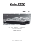
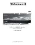
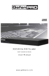
1
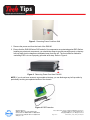
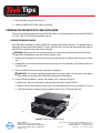
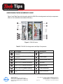
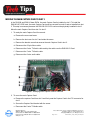
Tech Tips
INSTALLING THE DX8100-ISCI SCSI CARD
WITH SATABOY
April 16, 2008
Helpful Tips for Pelco Products
TOOLS NEEDED
Qty
Description
1
Phillips screwdriver #1 (nonmagnetic)
1
Properly grounded electrostatic discharge (ESD) wrist
strap and mat
4
Small containers for storing screws (optional)
GETTING READY
Before you install the DX8100-ISCI SCSI card, familiarize yourself with the instructions in this Tech
Tip. The steps to install the external video storage upgrade are summarized as follows:
1. Unpack the DX8100-ISCI kit and check that you have all the necessary kit components.
2. Verify that you have the required tools to install the SCSI card. For information about the tools
required to install the SCSI card, refer to Tools Needed table above.
3. Shut down the DX8100 Series DVR. For information about shutting down the DX8100, refer to the
DX8100 Installation Manual, Operation and Programming manual, or DX8100 Server online Help.
4.
Unplug the power cord from the wall socket.
WARNING: It is critical that the unit be unplugged for your safety. You must remove the power
cord because current continues to flow through the DX8100 even when the unit is off. Remove
the power cord from the wall socket first, and then from the rear of the DVR.
World Headquarters
3500 Pelco Way, Clovis, California 93612 USA
USA & Canada Tel: 800/289-9100 Fax: 800/289-9150
International Tel: 1-559/292-1981 Fax: 1-559/348-1120
www.pelco.com
Pelco and the Pelco logo are registered trademarks of Pelco, Inc.
Information subject to change without notice.
©Copyright 2008, Pelco, Inc. All rights reserved.
Page 1 of 21
DX8100-ISCI_SCSI_CARD_SATABoy.fm
Tech Tips
Helpful Tips for Pelco Products
Figure 2. Removing Power Cord from Wall
1. Remove the power cord from the back of the DX8100.
2. Ensure that the DX8100 Series DVR and all of its components are protected against ESD. Before
handling any electronic components, you should take steps to ground yourself properly so that any
built-up static electric charges are dissipated away from the unit. The most effective method for
combating ESD is to use a properly grounded wrist strap. Refer to Figure 4.
Figure 3. Removing Power Cord from DX8100
NOTE: If you do not have access to a grounded wrist strap, you can discharge any built-up static by
periodically touching an unpainted section of the chassis.
Figure 4. ESD Protection
World Headquarters
3500 Pelco Way, Clovis, California 93612 USA
USA & Canada Tel: 800/289-9100 Fax: 800/289-9150
International Tel: 1-559/292-1981 Fax: 1-559/348-1120
www.pelco.com
Pelco and the Pelco logo are registered trademarks of Pelco, Inc.
Information subject to change without notice.
©Copyright 2008, Pelco, Inc. All rights reserved.
Page 2 of 21
DX8100-ISCI_SCSI_CARD_SATABoy.fm
Tech Tips
Helpful Tips for Pelco Products
1. Move the Main Capture Card to slot 3.
2. Install the DX8100-ISCI SCSI card and cabling.
PREPARING THE DX8100 FOR SCSI CARD INSTALLATION
This section describes how to access the DX8100 interior. For information about mounting the DX8100
in a rack, refer to the DX8100 Installation manual.
OPENING THE DX8100 CHASSIS
If the DX8100 is mounted in a rack, the DX8100 must be removed from the rack. Two people might be
required to lift and remove the DX8100. To move the DX8100 to an area that will provide full access to
the DX8100’s internal components do the following:
WARNING: Make sure the unit is turned off and you are wearing a properly grounded ESD wrist
strap before attempting to open the DX8100 chassis cover.
1. Disconnect any cables or connections that may restrict access or interfere with the removal of the
unit.
2. (If applicable) Unscrew the fasteners that are securing the unit in the rack, and carefully lift the unit
out of the rack.
3. Place the DX8100 on a flat surface with ample workspace.
WARNING: The chassis assembly includes parts with sharp edges. To avoid injury, use caution
when working in and around the DX8100’s chassis and components.
4. Using a Phillips screwdriver, remove the chassis cover, referring to Figure 5:
a. Remove the top two screws on the left and right side panels of the DX8100.
b. Remove the four silver screws (on the top of the unit) fastening the cover to the back of the unit.
c. Carefully remove the chassis cover by sliding it back and up. Set aside the cover.
Figure 5. Removing Chassis Cover
World Headquarters
3500 Pelco Way, Clovis, California 93612 USA
USA & Canada Tel: 800/289-9100 Fax: 800/289-9150
International Tel: 1-559/292-1981 Fax: 1-559/348-1120
www.pelco.com
Pelco and the Pelco logo are registered trademarks of Pelco, Inc.
Information subject to change without notice.
©Copyright 2008, Pelco, Inc. All rights reserved.
Page 3 of 21
DX8100-ISCI_SCSI_CARD_SATABoy.fm
Tech Tips
Helpful Tips for Pelco Products
UNDERSTANDING THE DX8100 COMPONENT LAYOUT
Figure 6 and Table B provide information about the DX8100’s slot assignments and major components.
(Slots on the motherboard are labeled differently.)
Figure 6. DX8100 Interior
Table B. DX8100 Slot Assignments and Major Components
Item
Description
Item
Description
Slot 1: PTZ card installed in PCI
connector
CPU
Slot 2: Capture Card installed in PCI
connector
Power supply
Slot 3: PCI connector
DIMM sockets (RAM)
Slot 4: x1 PCI Express connectors
DVD-RW
Slot 5: x1 PCI Express connectors
Hard drive bay
Slot 6: x16 PCI Express connector
Front cross-brace
Slot 7: Optional Expansion Unit I/O
card
Rear cross-brace
World Headquarters
3500 Pelco Way, Clovis, California 93612 USA
USA & Canada Tel: 800/289-9100 Fax: 800/289-9150
International Tel: 1-559/292-1981 Fax: 1-559/348-1120
www.pelco.com
Pelco and the Pelco logo are registered trademarks of Pelco, Inc.
Information subject to change without notice.
©Copyright 2008, Pelco, Inc. All rights reserved.
Page 4 of 21
DX8100-ISCI_SCSI_CARD_SATABoy.fm
Tech Tips
Helpful Tips for Pelco Products
MOVING THE MAIN CAPTURE CARD TO SLOT 3
In the DX8108 and DX8116 base DVRs, the main Capture Card is installed in slot 2. To install the
DX8100-ISCI SCSI card, the main Capture Card must be removed from slot 2 and re-installed into slot
3. This step is necessary because the DX8100-ISCI SCSI card must be physically installed in slot 2.
Move the main Capture Card from slot 2 to slot 3:
1. To ready the main Capture Card for removal:
a. Remove the rear cross-brace.
b. Remove the slot cover for slot 3 and retain the screw.
c. Remove the bracket screw that secures the main Capture Card in slot 2.
d. Disconnect the 32-pin ribbon cable.
e. Disconnect the 5-wire TV/Audio cable and lay the cable over the DX8100 I/O Card.
f. Disconnect the 7-wire TV/Audio cable.
g. Disconnect the 2-wire audio cable.
Figure 7. Readying Main Capture Card for Removal
2. To move the main Capture Card:
a. Remove the capture Card from slot 2 and firmly seat the Capture Card in the PCI connector for
slot 3.
b. Secure the Capture Card bracket with the screw.
c. Reconnect the 5-wire TV/Audio cable.
World Headquarters
3500 Pelco Way, Clovis, California 93612 USA
USA & Canada Tel: 800/289-9100 Fax: 800/289-9150
International Tel: 1-559/292-1981 Fax: 1-559/348-1120
www.pelco.com
Pelco and the Pelco logo are registered trademarks of Pelco, Inc.
Information subject to change without notice.
©Copyright 2008, Pelco, Inc. All rights reserved.
Page 5 of 21
DX8100-ISCI_SCSI_CARD_SATABoy.fm
Tech Tips
Helpful Tips for Pelco Products
d. Reconnect the 7-wire TV/Audio cable.
e. Reconnect the 2-wire audio cable.
Figure 8. Moving Main Capture Card
INSTALLING THE DX8100 SCSI CARD
The DX8100-ISCI SCSI card is shipped separately. The SCSI card is installed in the PCI slot 2 on the
motherboard.
To Install the DX8100-ISCI SCSI card:
1. Verify that the main Capture Card is installed in slot 3. For information about moving the main
Capture Card from slot 2 to slot 3, refer to Moving the Main Capture Card to Slot 3 on page 5.
2. To install the SCSI card into slot 2:
a. Firmly seat the DX8100-ISCI SCSI card in the PCI connector for slot 2.
b. Secure the DX8100-ISCI SCSI card bracket with the screw removed from slot 3.
c. Reconnect the 32-pin ribbon cable to the first 32-pin connector (on the main Capture Card) in
slot 3.
3. Replace the rear cross-brace.
Note: Connect the 68-pin high density cable to the bottom port of the SCSI card. Connect the other
side to Host 0 on the bottom port of the SATABoy.
World Headquarters
3500 Pelco Way, Clovis, California 93612 USA
USA & Canada Tel: 800/289-9100 Fax: 800/289-9150
International Tel: 1-559/292-1981 Fax: 1-559/348-1120
www.pelco.com
Pelco and the Pelco logo are registered trademarks of Pelco, Inc.
Information subject to change without notice.
©Copyright 2008, Pelco, Inc. All rights reserved.
Page 6 of 21
DX8100-ISCI_SCSI_CARD_SATABoy.fm
Tech Tips
Helpful Tips for Pelco Products
4. This completes installation of the SCSI card. Next, reassemble the DX8100 and then install the
SATABoy. For information about reassembling the unit, refer to Reassembling the Unit on page 7.
REASSEMBLING THE UNIT
1. Replace the chassis cover using the screws you removed from the side and rear of the unit. Refer
to Figure 10.
2. Attach the silver product label that came with your upgrade kit to the inside of your DVR’s front
door.
a. Remove the paper backing from the product label.
b. Carefully place the label, adhesive-side down, on a free section of the inside of the door.
c. Press down firmly to ensure that the label properly adheres to the inside of the door.
World Headquarters
3500 Pelco Way, Clovis, California 93612 USA
USA & Canada Tel: 800/289-9100 Fax: 800/289-9150
International Tel: 1-559/292-1981 Fax: 1-559/348-1120
www.pelco.com
Pelco and the Pelco logo are registered trademarks of Pelco, Inc.
Information subject to change without notice.
©Copyright 2008, Pelco, Inc. All rights reserved.
Page 7 of 21
DX8100-ISCI_SCSI_CARD_SATABoy.fm
Tech Tips
Helpful Tips for Pelco Products
NOTE: In the event that your unit or its components require service, specific labels must be present
and appropriately affixed to the unit’s door. Pelco product support personnel use these labels to
identify the exact components installed in your system. A separate product label is required for each
upgrade component installed on the DX8100.
1. Reinstall the unit in a rack enclosure if necessary, and reconnect all cables and peripheral
equipment you removed earlier.
2. The final step is to install the SATABoy.
SETTING UP THE SATABOY
For New SATABoy Only:
Install the HDs into the SATABoy system:
1. Lift the HD latch and place it into the SATABoy system.
2. Push the round button down to secure HD in place. (See Figure 1)
3. The system can have 8 HDs or 14 HDs.
a. Install the drive covers for 8 HDs / 14 HDs unit.
4. Plug in all the cables.
a. Connect SCSI cable:
•
The SCSI cable that connects to the system shall be connected to the BOTTOM port of
HOST 0 of SATABoy.
World Headquarters
3500 Pelco Way, Clovis, California 93612 USA
USA & Canada Tel: 800/289-9100 Fax: 800/289-9150
International Tel: 1-559/292-1981 Fax: 1-559/348-1120
www.pelco.com
Pelco and the Pelco logo are registered trademarks of Pelco, Inc.
Information subject to change without notice.
©Copyright 2008, Pelco, Inc. All rights reserved.
Page 8 of 21
DX8100-ISCI_SCSI_CARD_SATABoy.fm
Tech Tips
Helpful Tips for Pelco Products
Figure 2
1. Connect to a PC and SATABoy with Cat5 Crossover cable.
2. Turn on the SATABoy and wait until three LEDs come on. (See Figure 3)
3. Turn on the PC.
For New SATABoy with 8 or 14 HDs: Configure Computer
1.
Right click on My Network Place on the desktop and then left click Properties.
2.
Right click Local Area Connection and then left click Properties.
3.
Left click Internet Protocol (TCP/IP).
4.
Click Properties.
5. Select Use the following IP address. (See Figure 4)
a. Record the current IP and Subnet addresses on the travel tag for later to use.
b. Change the IP address to 10.11.12.13.
c. Change the Subnet mask to 255.255.255.0.
d. Click OK.
e. Click Close.
World Headquarters
3500 Pelco Way, Clovis, California 93612 USA
USA & Canada Tel: 800/289-9100 Fax: 800/289-9150
International Tel: 1-559/292-1981 Fax: 1-559/348-1120
www.pelco.com
Pelco and the Pelco logo are registered trademarks of Pelco, Inc.
Information subject to change without notice.
©Copyright 2008, Pelco, Inc. All rights reserved.
Page 9 of 21
DX8100-ISCI_SCSI_CARD_SATABoy.fm
Tech Tips
Helpful Tips for Pelco Products
13
Figure 4
Configure SATABoy with 8 or 14 HDs
1. Open the Internet Explorer
2. Highlight the address bar and type 10. 11. 12. 13 and press Enter.
3. Click the Login button.
4. Click Configure Network under the main menu.
5. On the Configure Network, type X.X.X.X next to the IP address where X.X.X.X is the individual
address assigned to each SATABoy. 192.168.0.2 is the sample IP address. (See Figure 5)
World Headquarters
3500 Pelco Way, Clovis, California 93612 USA
USA & Canada Tel: 800/289-9100 Fax: 800/289-9150
International Tel: 1-559/292-1981 Fax: 1-559/348-1120
www.pelco.com
Pelco and the Pelco logo are registered trademarks of Pelco, Inc.
Information subject to change without notice.
©Copyright 2008, Pelco, Inc. All rights reserved.
Page 10 of 21
DX8100-ISCI_SCSI_CARD_SATABoy.fm
Tech Tips
Helpful Tips for Pelco Products
Figure 5
1. Click Save Configuration and close the screen.
2. Reset the SATABoy by turning off the unit for 10 seconds.
3. Unplug the Cat5 Crossover cable.
4. Plug in the network cables into the system and SATABoy
5. Power on SATABoy and wait for 60 seconds before opening Explorer.
Resume Computer Configuration
1. Right click My Network Places on the desktop and then left click Properties.
2. Right click Local Area Connection and then left click Properties.
3. Left click Internet Protocol (TCP/IP).
4. Click Properties.
World Headquarters
3500 Pelco Way, Clovis, California 93612 USA
USA & Canada Tel: 800/289-9100 Fax: 800/289-9150
International Tel: 1-559/292-1981 Fax: 1-559/348-1120
www.pelco.com
Pelco and the Pelco logo are registered trademarks of Pelco, Inc.
Information subject to change without notice.
©Copyright 2008, Pelco, Inc. All rights reserved.
Page 11 of 21
DX8100-ISCI_SCSI_CARD_SATABoy.fm
Tech Tips
Helpful Tips for Pelco Products
5. Under Use the following IP address: (See Figure 6)
a. Type the IP address that was recorded on the travel tag next to IP address.
b. Type the Subnet mask that was recorded on the travel tag next to Subnet mask.
Figure 6
1.
Click OK.
2.
Click Close.
Resume SATABoy Configuration with 8 or 14 HDs
1. Open the Internet Explorer on the desktop.
2. Highlight the address bar and type X.X.X.X where X.X.X.X was chosen under Network Setting.
(See Figure 5)
3. Click the Login button
4. Select the RAID INFORMATION option from the main menu.
5. Click the Volumes tab and check to make sure there is no free space listed on the screen.
World Headquarters
3500 Pelco Way, Clovis, California 93612 USA
USA & Canada Tel: 800/289-9100 Fax: 800/289-9150
International Tel: 1-559/292-1981 Fax: 1-559/348-1120
www.pelco.com
Pelco and the Pelco logo are registered trademarks of Pelco, Inc.
Information subject to change without notice.
©Copyright 2008, Pelco, Inc. All rights reserved.
Page 12 of 21
DX8100-ISCI_SCSI_CARD_SATABoy.fm
Tech Tips
Helpful Tips for Pelco Products
Figure 7
Figure 8
1. Make sure to turn on the SATABoys and wait until the three SATABoy LED lights come on before
starting the DX8100.
2.
Turn on the DX8100.
World Headquarters
3500 Pelco Way, Clovis, California 93612 USA
USA & Canada Tel: 800/289-9100 Fax: 800/289-9150
International Tel: 1-559/292-1981 Fax: 1-559/348-1120
www.pelco.com
Pelco and the Pelco logo are registered trademarks of Pelco, Inc.
Information subject to change without notice.
©Copyright 2008, Pelco, Inc. All rights reserved.
Page 13 of 21
DX8100-ISCI_SCSI_CARD_SATABoy.fm
Tech Tips
Helpful Tips for Pelco Products
For Upgrading/Downgrading default SATABoy HDs configurations: (i.e. SATABoy HDs from 8
HDs to 14 HDs or 14 HDs to 8 HDs)
1. Open the Internet Explorer on the desktop.
2. High light the address bar and type X.X.X.X where X.X.X.X was chosen under Network Setting.
(See Figure 5)
3.
Click Login button
4. Delete Volume(s)
a. Select the CONFIGURE VOLUMES option under the main menu.
b. Select the Delete Volume tab.
c. Place a dot next to Delete Volume. (See Figure 9)
d. Click Delete Volume.
e. Place a checkmark above the Confirm Delete Commend and click Confirm Delete Commend.
f. Click Back.
g. Repeat steps a through e to delete each volume.
Figure 9
5. Delete Raid array.
a. Select Configure Raid under the main menu.
b. Select the Delete Array tab.
c. Click Delete Array.
d. Click Confirm button.
World Headquarters
3500 Pelco Way, Clovis, California 93612 USA
USA & Canada Tel: 800/289-9100 Fax: 800/289-9150
International Tel: 1-559/292-1981 Fax: 1-559/348-1120
www.pelco.com
Pelco and the Pelco logo are registered trademarks of Pelco, Inc.
Information subject to change without notice.
©Copyright 2008, Pelco, Inc. All rights reserved.
Page 14 of 21
DX8100-ISCI_SCSI_CARD_SATABoy.fm
Tech Tips
Helpful Tips for Pelco Products
e. Click Back.
f. Make sure to delete each raid array.
6. Add Raid Array. (See Figure 10)
a. Select Add Array tab.
b. Type name next to array name. Raid1 is a sample name.
c. Select all disks except Pool Spare.
d. Click Create Raid Set button.
e. Click Back.
Figure 10
7. Add Volumes Note: The first volume is automatically set up after the Raid array is created. More
Volumes need to be created based on the HDs of SATABoy (three volumes for 14 HDs SATABoy
and two volumes for 8HDs SATABoy). The volume size limit is 1.7 TB.
a. Select the CONFIGURE VOLUMES option under the main menu.
b. Select ADD VOLUME.
c. Change the unit by placing a dot next to % and click Change Units.
d. Click Back.
e. Type the name next to Enter the name for the new volume. Volume #2 is a sample name
f. Type 100 next to Enter the size of the new volume in % of array capacity.
g. Place a check mark next to Limit volume size to less than 2TB.
h. Select LUN0 next to Select LUN for new Volume on port 0. (Select LUN1 for Volume 2 and so
on)
World Headquarters
3500 Pelco Way, Clovis, California 93612 USA
USA & Canada Tel: 800/289-9100 Fax: 800/289-9150
International Tel: 1-559/292-1981 Fax: 1-559/348-1120
www.pelco.com
Pelco and the Pelco logo are registered trademarks of Pelco, Inc.
Information subject to change without notice.
©Copyright 2008, Pelco, Inc. All rights reserved.
Page 15 of 21
DX8100-ISCI_SCSI_CARD_SATABoy.fm
Tech Tips
Helpful Tips for Pelco Products
i. Click Create Volume. Enter settings according to Figure 11.
Figure 11
j. After the volume is created, verify that there is no free space remaining in the raid array.
Figure 12
World Headquarters
3500 Pelco Way, Clovis, California 93612 USA
USA & Canada Tel: 800/289-9100 Fax: 800/289-9150
International Tel: 1-559/292-1981 Fax: 1-559/348-1120
www.pelco.com
Pelco and the Pelco logo are registered trademarks of Pelco, Inc.
Information subject to change without notice.
©Copyright 2008, Pelco, Inc. All rights reserved.
Page 16 of 21
DX8100-ISCI_SCSI_CARD_SATABoy.fm
Tech Tips
Helpful Tips for Pelco Products
k. Click the Back button and repeat steps from e to i until all volumes are created. (See Figure 13)
Figure 13
Configure the SATABoy to SCSI card --- Final steps for new SATABoy or modified SATABoy.
Note: Need to wait 4-5 hours for raid array to initialize if a new raid array is created.
1. Make sure the SCSI cable is connected between the SCSI card and the DX8100.
2. Start the DX8100.
3. Open the Computer Management by selecting the Start button, select Run and type
compmgmt.msc. Click OK or press Enter.
4. Click Disk Management.
5. Click Next on the Welcome Wizard.
6. Make sure all the disks are selected and click Next. (See Figure 14)
Figure 14
World Headquarters
3500 Pelco Way, Clovis, California 93612 USA
USA & Canada Tel: 800/289-9100 Fax: 800/289-9150
International Tel: 1-559/292-1981 Fax: 1-559/348-1120
www.pelco.com
Pelco and the Pelco logo are registered trademarks of Pelco, Inc.
Information subject to change without notice.
©Copyright 2008, Pelco, Inc. All rights reserved.
Page 17 of 21
DX8100-ISCI_SCSI_CARD_SATABoy.fm
Tech Tips
Helpful Tips for Pelco Products
7. Do not select any disk(s) on Select Disk to Convert, just click Next. (See Figure 15)
Figure 15
8. Click Finish.
9. Right click Unallocated space next to Disk2 and select New Partition. (See Figure 16)
Figure 16
World Headquarters
3500 Pelco Way, Clovis, California 93612 USA
USA & Canada Tel: 800/289-9100 Fax: 800/289-9150
International Tel: 1-559/292-1981 Fax: 1-559/348-1120
www.pelco.com
Pelco and the Pelco logo are registered trademarks of Pelco, Inc.
Information subject to change without notice.
©Copyright 2008, Pelco, Inc. All rights reserved.
Page 18 of 21
DX8100-ISCI_SCSI_CARD_SATABoy.fm
Tech Tips
Helpful Tips for Pelco Products
10. Select Extended partition and click Next. (See Figure 17)
Figure 17
11. Click Next, Next and Finish.
Figure 18
World Headquarters
3500 Pelco Way, Clovis, California 93612 USA
USA & Canada Tel: 800/289-9100 Fax: 800/289-9150
International Tel: 1-559/292-1981 Fax: 1-559/348-1120
www.pelco.com
Pelco and the Pelco logo are registered trademarks of Pelco, Inc.
Information subject to change without notice.
©Copyright 2008, Pelco, Inc. All rights reserved.
Page 19 of 21
DX8100-ISCI_SCSI_CARD_SATABoy.fm
Tech Tips
Helpful Tips for Pelco Products
13. Right-click and select New Logical drive and click Next on New Partition Wizard. (See Figure 19)
Figure 19
14. Click Next, Next and Next.
Figure 20
1.
Place a checkmark next to Perform a quick format. (See Figure 20)
2.
Click Next and Finish.
3.
Repeat above steps 9-17 for each new disk.
World Headquarters
3500 Pelco Way, Clovis, California 93612 USA
USA & Canada Tel: 800/289-9100 Fax: 800/289-9150
International Tel: 1-559/292-1981 Fax: 1-559/348-1120
www.pelco.com
Pelco and the Pelco logo are registered trademarks of Pelco, Inc.
Information subject to change without notice.
©Copyright 2008, Pelco, Inc. All rights reserved.
Page 20 of 21
DX8100-ISCI_SCSI_CARD_SATABoy.fm
Tech Tips
Helpful Tips for Pelco Products
Apply the Labels
1. Print the model and serial labels.
2. Print the IP address and Subnet mask label. Each system should have a different IP address.
3. Place the labels on top of SATABoy. (See Figure 21)
Figure 21
World Headquarters
3500 Pelco Way, Clovis, California 93612 USA
USA & Canada Tel: 800/289-9100 Fax: 800/289-9150
International Tel: 1-559/292-1981 Fax: 1-559/348-1120
www.pelco.com
Pelco and the Pelco logo are registered trademarks of Pelco, Inc.
Information subject to change without notice.
©Copyright 2008, Pelco, Inc. All rights reserved.
Page 21 of 21
DX8100-ISCI_SCSI_CARD_SATABoy.fm