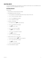
1
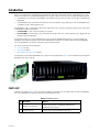
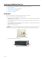
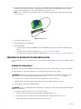
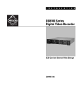
DX8100-ISCI SCSI
and DX9200HDDI
Installation Manual
DX8100 Digital Video Recorder
C2635M (1/07)
Contents
Introduction . . . . . . . . . . . . . . . . . . . . . . . . . . . . . . . . . . . . . . . . . . . . . . . . . . . . . . . . . . . . . . . . . . . . . . . . . . . . . . . . . . . . . . . . . . . . . . . . . . . . . . . . . . 7
Parts List . . . . . . . . . . . . . . . . . . . . . . . . . . . . . . . . . . . . . . . . . . . . . . . . . . . . . . . . . . . . . . . . . . . . . . . . . . . . . . . . . . . . . . . . . . . . . . . . . . . . . . . 7
Tools Needed . . . . . . . . . . . . . . . . . . . . . . . . . . . . . . . . . . . . . . . . . . . . . . . . . . . . . . . . . . . . . . . . . . . . . . . . . . . . . . . . . . . . . . . . . . . . . . . . . . . . 8
Other DX8100 Optional Accessories . . . . . . . . . . . . . . . . . . . . . . . . . . . . . . . . . . . . . . . . . . . . . . . . . . . . . . . . . . . . . . . . . . . . . . . . . . . . . . . . . . 8
Installing the DX8100-ISCI SCSI Card . . . . . . . . . . . . . . . . . . . . . . . . . . . . . . . . . . . . . . . . . . . . . . . . . . . . . . . . . . . . . . . . . . . . . . . . . . . . . . . . . . . . . 9
Getting Ready . . . . . . . . . . . . . . . . . . . . . . . . . . . . . . . . . . . . . . . . . . . . . . . . . . . . . . . . . . . . . . . . . . . . . . . . . . . . . . . . . . . . . . . . . . . . . . . . . . . 9
Preparing the DX8100 for SCSI Card Installation . . . . . . . . . . . . . . . . . . . . . . . . . . . . . . . . . . . . . . . . . . . . . . . . . . . . . . . . . . . . . . . . . . . . . . . 10
Opening the DX8100 Chassis . . . . . . . . . . . . . . . . . . . . . . . . . . . . . . . . . . . . . . . . . . . . . . . . . . . . . . . . . . . . . . . . . . . . . . . . . . . . . . . . . . 10
Understanding the DX8100 Component Layout . . . . . . . . . . . . . . . . . . . . . . . . . . . . . . . . . . . . . . . . . . . . . . . . . . . . . . . . . . . . . . . . . . . . 11
Moving the Main Capture Card to Slot 3 . . . . . . . . . . . . . . . . . . . . . . . . . . . . . . . . . . . . . . . . . . . . . . . . . . . . . . . . . . . . . . . . . . . . . . . . . . . . . 12
Installing the DX8100 SCSI Card . . . . . . . . . . . . . . . . . . . . . . . . . . . . . . . . . . . . . . . . . . . . . . . . . . . . . . . . . . . . . . . . . . . . . . . . . . . . . . . . . . . . 13
Reassembling the Unit . . . . . . . . . . . . . . . . . . . . . . . . . . . . . . . . . . . . . . . . . . . . . . . . . . . . . . . . . . . . . . . . . . . . . . . . . . . . . . . . . . . . . . . . . . . . 14
Setting Up the DX9200HDDI . . . . . . . . . . . . . . . . . . . . . . . . . . . . . . . . . . . . . . . . . . . . . . . . . . . . . . . . . . . . . . . . . . . . . . . . . . . . . . . . . . . . . . . . . . . . 15
Installing the Hard Drives . . . . . . . . . . . . . . . . . . . . . . . . . . . . . . . . . . . . . . . . . . . . . . . . . . . . . . . . . . . . . . . . . . . . . . . . . . . . . . . . . . . . . . . . . 15
Configuring the DX9200HDDI . . . . . . . . . . . . . . . . . . . . . . . . . . . . . . . . . . . . . . . . . . . . . . . . . . . . . . . . . . . . . . . . . . . . . . . . . . . . . . . . . . . . . . 16
Configuring a Single RAID Level 5 Array . . . . . . . . . . . . . . . . . . . . . . . . . . . . . . . . . . . . . . . . . . . . . . . . . . . . . . . . . . . . . . . . . . . . . . . . . 17
Configuring a Single RAID Level 5 Array with Hot Spare . . . . . . . . . . . . . . . . . . . . . . . . . . . . . . . . . . . . . . . . . . . . . . . . . . . . . . . . . . . . 21
Configuring Two RAID Level 5 Arrays . . . . . . . . . . . . . . . . . . . . . . . . . . . . . . . . . . . . . . . . . . . . . . . . . . . . . . . . . . . . . . . . . . . . . . . . . . . 23
Configuring Two RAID Level 5 Arrays with Hot Spare . . . . . . . . . . . . . . . . . . . . . . . . . . . . . . . . . . . . . . . . . . . . . . . . . . . . . . . . . . . . . . . 27
Deleting Arrays . . . . . . . . . . . . . . . . . . . . . . . . . . . . . . . . . . . . . . . . . . . . . . . . . . . . . . . . . . . . . . . . . . . . . . . . . . . . . . . . . . . . . . . . . . . . . . . . . 31
Deleting One Array . . . . . . . . . . . . . . . . . . . . . . . . . . . . . . . . . . . . . . . . . . . . . . . . . . . . . . . . . . . . . . . . . . . . . . . . . . . . . . . . . . . . . . . . . . 31
Deleting Two Arrays . . . . . . . . . . . . . . . . . . . . . . . . . . . . . . . . . . . . . . . . . . . . . . . . . . . . . . . . . . . . . . . . . . . . . . . . . . . . . . . . . . . . . . . . . 33
Connecting the DX8100 to the DX9200HDDI . . . . . . . . . . . . . . . . . . . . . . . . . . . . . . . . . . . . . . . . . . . . . . . . . . . . . . . . . . . . . . . . . . . . . . . . . . . . . . . 35
Configuring the DX8100 to Access the DX9200HDDI . . . . . . . . . . . . . . . . . . . . . . . . . . . . . . . . . . . . . . . . . . . . . . . . . . . . . . . . . . . . . . . . . . . . . . . . 36
Configuration Instructions for Storage Arrays up to 2.0 TB . . . . . . . . . . . . . . . . . . . . . . . . . . . . . . . . . . . . . . . . . . . . . . . . . . . . . . . . . . . . . . . 36
Configuration Instructions for Storage Arrays Above 2.0 TB . . . . . . . . . . . . . . . . . . . . . . . . . . . . . . . . . . . . . . . . . . . . . . . . . . . . . . . . . . . . . . 46
C2635M (1/07)
3
List of Illustrations
1
2
3
4
5
6
7
8
9
10
11
12
13
14
15
16
17
18
19
20
21
22
23
24
25
26
27
28
29
30
31
32
33
34
35
36
37
38
39
40
41
42
43
44
45
46
47
48
49
50
51
52
53
54
55
56
57
58
59
60
4
DX8100 SCSI Card and DX9200HDDI Storage Unit . . . . . . . . . . . . . . . . . . . . . . . . . . . . . . . . . . . . . . . . . . . . . . . . . . . . . . . . . . . . . . . . . . . . . . 7
Removing Power Cord from Wall . . . . . . . . . . . . . . . . . . . . . . . . . . . . . . . . . . . . . . . . . . . . . . . . . . . . . . . . . . . . . . . . . . . . . . . . . . . . . . . . . . . . 9
Removing Power Cord from DX8100 . . . . . . . . . . . . . . . . . . . . . . . . . . . . . . . . . . . . . . . . . . . . . . . . . . . . . . . . . . . . . . . . . . . . . . . . . . . . . . . . . 9
ESD Protection . . . . . . . . . . . . . . . . . . . . . . . . . . . . . . . . . . . . . . . . . . . . . . . . . . . . . . . . . . . . . . . . . . . . . . . . . . . . . . . . . . . . . . . . . . . . . . . . . 10
Removing Chassis Cover. . . . . . . . . . . . . . . . . . . . . . . . . . . . . . . . . . . . . . . . . . . . . . . . . . . . . . . . . . . . . . . . . . . . . . . . . . . . . . . . . . . . . . . . . . 11
DX8100 Interior. . . . . . . . . . . . . . . . . . . . . . . . . . . . . . . . . . . . . . . . . . . . . . . . . . . . . . . . . . . . . . . . . . . . . . . . . . . . . . . . . . . . . . . . . . . . . . . . . 11
Readying Main Capture Card for Removal . . . . . . . . . . . . . . . . . . . . . . . . . . . . . . . . . . . . . . . . . . . . . . . . . . . . . . . . . . . . . . . . . . . . . . . . . . . . 12
Moving Main Capture Card . . . . . . . . . . . . . . . . . . . . . . . . . . . . . . . . . . . . . . . . . . . . . . . . . . . . . . . . . . . . . . . . . . . . . . . . . . . . . . . . . . . . . . . 13
Installing the SCSI Card . . . . . . . . . . . . . . . . . . . . . . . . . . . . . . . . . . . . . . . . . . . . . . . . . . . . . . . . . . . . . . . . . . . . . . . . . . . . . . . . . . . . . . . . . . 13
Replacing Chassis Cover. . . . . . . . . . . . . . . . . . . . . . . . . . . . . . . . . . . . . . . . . . . . . . . . . . . . . . . . . . . . . . . . . . . . . . . . . . . . . . . . . . . . . . . . . . 14
DX9200HDDI Hard Drive Tray . . . . . . . . . . . . . . . . . . . . . . . . . . . . . . . . . . . . . . . . . . . . . . . . . . . . . . . . . . . . . . . . . . . . . . . . . . . . . . . . . . . . . . 15
DX9200HDDI Control Panel . . . . . . . . . . . . . . . . . . . . . . . . . . . . . . . . . . . . . . . . . . . . . . . . . . . . . . . . . . . . . . . . . . . . . . . . . . . . . . . . . . . . . . . 16
Accessing the Main Menu . . . . . . . . . . . . . . . . . . . . . . . . . . . . . . . . . . . . . . . . . . . . . . . . . . . . . . . . . . . . . . . . . . . . . . . . . . . . . . . . . . . . . . . . 17
Configuring a Single RAID Level 5 Array . . . . . . . . . . . . . . . . . . . . . . . . . . . . . . . . . . . . . . . . . . . . . . . . . . . . . . . . . . . . . . . . . . . . . . . . . . . . . 18
Choosing the RAID Level . . . . . . . . . . . . . . . . . . . . . . . . . . . . . . . . . . . . . . . . . . . . . . . . . . . . . . . . . . . . . . . . . . . . . . . . . . . . . . . . . . . . . . . . . 18
Specifying the Number of Hard Drives in the Array. . . . . . . . . . . . . . . . . . . . . . . . . . . . . . . . . . . . . . . . . . . . . . . . . . . . . . . . . . . . . . . . . . . . . 18
Returning to the Main Menu . . . . . . . . . . . . . . . . . . . . . . . . . . . . . . . . . . . . . . . . . . . . . . . . . . . . . . . . . . . . . . . . . . . . . . . . . . . . . . . . . . . . . . 19
Restarting DX9200HDDI . . . . . . . . . . . . . . . . . . . . . . . . . . . . . . . . . . . . . . . . . . . . . . . . . . . . . . . . . . . . . . . . . . . . . . . . . . . . . . . . . . . . . . . . . . 19
Single RAID Level 5 Array Initialization Status . . . . . . . . . . . . . . . . . . . . . . . . . . . . . . . . . . . . . . . . . . . . . . . . . . . . . . . . . . . . . . . . . . . . . . . . 19
Single DX8100 to DX9200HDDI SCSI Connection . . . . . . . . . . . . . . . . . . . . . . . . . . . . . . . . . . . . . . . . . . . . . . . . . . . . . . . . . . . . . . . . . . . . . . 35
Dual DX8100 to DX9200HDDI SCSI Connection. . . . . . . . . . . . . . . . . . . . . . . . . . . . . . . . . . . . . . . . . . . . . . . . . . . . . . . . . . . . . . . . . . . . . . . . 35
Shut Down Dialog Box . . . . . . . . . . . . . . . . . . . . . . . . . . . . . . . . . . . . . . . . . . . . . . . . . . . . . . . . . . . . . . . . . . . . . . . . . . . . . . . . . . . . . . . . . . . 36
Start Button Shortcut Menu . . . . . . . . . . . . . . . . . . . . . . . . . . . . . . . . . . . . . . . . . . . . . . . . . . . . . . . . . . . . . . . . . . . . . . . . . . . . . . . . . . . . . . . 36
My Computer Quick Menu . . . . . . . . . . . . . . . . . . . . . . . . . . . . . . . . . . . . . . . . . . . . . . . . . . . . . . . . . . . . . . . . . . . . . . . . . . . . . . . . . . . . . . . . 37
Computer Management Window . . . . . . . . . . . . . . . . . . . . . . . . . . . . . . . . . . . . . . . . . . . . . . . . . . . . . . . . . . . . . . . . . . . . . . . . . . . . . . . . . . . 37
Write Signature and Upgrade Disk Wizard . . . . . . . . . . . . . . . . . . . . . . . . . . . . . . . . . . . . . . . . . . . . . . . . . . . . . . . . . . . . . . . . . . . . . . . . . . . 38
Select Disk to Write Signature Dialog Box . . . . . . . . . . . . . . . . . . . . . . . . . . . . . . . . . . . . . . . . . . . . . . . . . . . . . . . . . . . . . . . . . . . . . . . . . . . 38
Select Disks to Upgrade Wizard Dialog Box . . . . . . . . . . . . . . . . . . . . . . . . . . . . . . . . . . . . . . . . . . . . . . . . . . . . . . . . . . . . . . . . . . . . . . . . . . 39
Completing the Write Signature and Upgrade Disk Wizard . . . . . . . . . . . . . . . . . . . . . . . . . . . . . . . . . . . . . . . . . . . . . . . . . . . . . . . . . . . . . . 39
Unallocated Space Shortcut Menu. . . . . . . . . . . . . . . . . . . . . . . . . . . . . . . . . . . . . . . . . . . . . . . . . . . . . . . . . . . . . . . . . . . . . . . . . . . . . . . . . . 40
Create Partition Wizard . . . . . . . . . . . . . . . . . . . . . . . . . . . . . . . . . . . . . . . . . . . . . . . . . . . . . . . . . . . . . . . . . . . . . . . . . . . . . . . . . . . . . . . . . . 40
Select Partition Dialog Box. . . . . . . . . . . . . . . . . . . . . . . . . . . . . . . . . . . . . . . . . . . . . . . . . . . . . . . . . . . . . . . . . . . . . . . . . . . . . . . . . . . . . . . . 41
Specify Partition Size Dialog Box . . . . . . . . . . . . . . . . . . . . . . . . . . . . . . . . . . . . . . . . . . . . . . . . . . . . . . . . . . . . . . . . . . . . . . . . . . . . . . . . . . . 41
Assign Drive Letter or Path Dialog Box . . . . . . . . . . . . . . . . . . . . . . . . . . . . . . . . . . . . . . . . . . . . . . . . . . . . . . . . . . . . . . . . . . . . . . . . . . . . . . 42
Format Partition Dialog Box . . . . . . . . . . . . . . . . . . . . . . . . . . . . . . . . . . . . . . . . . . . . . . . . . . . . . . . . . . . . . . . . . . . . . . . . . . . . . . . . . . . . . . . 42
Completing the Create Partition Wizard. . . . . . . . . . . . . . . . . . . . . . . . . . . . . . . . . . . . . . . . . . . . . . . . . . . . . . . . . . . . . . . . . . . . . . . . . . . . . . 43
Drive Shortcut Menu. . . . . . . . . . . . . . . . . . . . . . . . . . . . . . . . . . . . . . . . . . . . . . . . . . . . . . . . . . . . . . . . . . . . . . . . . . . . . . . . . . . . . . . . . . . . . 43
Allocation Management Dialog Box. . . . . . . . . . . . . . . . . . . . . . . . . . . . . . . . . . . . . . . . . . . . . . . . . . . . . . . . . . . . . . . . . . . . . . . . . . . . . . . . . 44
Selecting the PDB Box . . . . . . . . . . . . . . . . . . . . . . . . . . . . . . . . . . . . . . . . . . . . . . . . . . . . . . . . . . . . . . . . . . . . . . . . . . . . . . . . . . . . . . . . . . . 44
Opening Drive Options Menu . . . . . . . . . . . . . . . . . . . . . . . . . . . . . . . . . . . . . . . . . . . . . . . . . . . . . . . . . . . . . . . . . . . . . . . . . . . . . . . . . . . . . . 44
Selecting Allocation Option for Each Drive . . . . . . . . . . . . . . . . . . . . . . . . . . . . . . . . . . . . . . . . . . . . . . . . . . . . . . . . . . . . . . . . . . . . . . . . . . . 45
Initializing Drive Allocation. . . . . . . . . . . . . . . . . . . . . . . . . . . . . . . . . . . . . . . . . . . . . . . . . . . . . . . . . . . . . . . . . . . . . . . . . . . . . . . . . . . . . . . . 45
Format Warning Dialog Box . . . . . . . . . . . . . . . . . . . . . . . . . . . . . . . . . . . . . . . . . . . . . . . . . . . . . . . . . . . . . . . . . . . . . . . . . . . . . . . . . . . . . . . 45
PDB Database Creation Progress Bar. . . . . . . . . . . . . . . . . . . . . . . . . . . . . . . . . . . . . . . . . . . . . . . . . . . . . . . . . . . . . . . . . . . . . . . . . . . . . . . . 45
Shut Down Dialog Box . . . . . . . . . . . . . . . . . . . . . . . . . . . . . . . . . . . . . . . . . . . . . . . . . . . . . . . . . . . . . . . . . . . . . . . . . . . . . . . . . . . . . . . . . . . 46
Start Button Shortcut Menu . . . . . . . . . . . . . . . . . . . . . . . . . . . . . . . . . . . . . . . . . . . . . . . . . . . . . . . . . . . . . . . . . . . . . . . . . . . . . . . . . . . . . . . 46
My Computer Quick Menu . . . . . . . . . . . . . . . . . . . . . . . . . . . . . . . . . . . . . . . . . . . . . . . . . . . . . . . . . . . . . . . . . . . . . . . . . . . . . . . . . . . . . . . . 46
Computer Management Window . . . . . . . . . . . . . . . . . . . . . . . . . . . . . . . . . . . . . . . . . . . . . . . . . . . . . . . . . . . . . . . . . . . . . . . . . . . . . . . . . . . 47
Write Signature and Upgrade Disk Wizard . . . . . . . . . . . . . . . . . . . . . . . . . . . . . . . . . . . . . . . . . . . . . . . . . . . . . . . . . . . . . . . . . . . . . . . . . . . 47
Select Disk to Write Signature Dialog Box . . . . . . . . . . . . . . . . . . . . . . . . . . . . . . . . . . . . . . . . . . . . . . . . . . . . . . . . . . . . . . . . . . . . . . . . . . . 48
Select Disks to Upgrade Wizard Dialog Box . . . . . . . . . . . . . . . . . . . . . . . . . . . . . . . . . . . . . . . . . . . . . . . . . . . . . . . . . . . . . . . . . . . . . . . . . . 48
Completing the Write Signature and Upgrade Disk Wizard . . . . . . . . . . . . . . . . . . . . . . . . . . . . . . . . . . . . . . . . . . . . . . . . . . . . . . . . . . . . . . 49
Unallocated Space Shortcut Menu. . . . . . . . . . . . . . . . . . . . . . . . . . . . . . . . . . . . . . . . . . . . . . . . . . . . . . . . . . . . . . . . . . . . . . . . . . . . . . . . . . 49
Create Partition Wizard . . . . . . . . . . . . . . . . . . . . . . . . . . . . . . . . . . . . . . . . . . . . . . . . . . . . . . . . . . . . . . . . . . . . . . . . . . . . . . . . . . . . . . . . . . 50
Select Partition Type Dialog Box . . . . . . . . . . . . . . . . . . . . . . . . . . . . . . . . . . . . . . . . . . . . . . . . . . . . . . . . . . . . . . . . . . . . . . . . . . . . . . . . . . . 50
Specify Partition Size Dialog Box . . . . . . . . . . . . . . . . . . . . . . . . . . . . . . . . . . . . . . . . . . . . . . . . . . . . . . . . . . . . . . . . . . . . . . . . . . . . . . . . . . . 50
Assign Drive Letter or Path Dialog Box . . . . . . . . . . . . . . . . . . . . . . . . . . . . . . . . . . . . . . . . . . . . . . . . . . . . . . . . . . . . . . . . . . . . . . . . . . . . . . 51
Format Partition Dialog Box . . . . . . . . . . . . . . . . . . . . . . . . . . . . . . . . . . . . . . . . . . . . . . . . . . . . . . . . . . . . . . . . . . . . . . . . . . . . . . . . . . . . . . . 51
Completing the Create Partition Wizard. . . . . . . . . . . . . . . . . . . . . . . . . . . . . . . . . . . . . . . . . . . . . . . . . . . . . . . . . . . . . . . . . . . . . . . . . . . . . . 52
Drive Shortcut Menu. . . . . . . . . . . . . . . . . . . . . . . . . . . . . . . . . . . . . . . . . . . . . . . . . . . . . . . . . . . . . . . . . . . . . . . . . . . . . . . . . . . . . . . . . . . . . 52
C2635M (1/07)
61
62
63
64
65
66
67
C2635M (1/07)
Allocation Management Dialog Box. . . . . . . . . . . . . . . . . . . . . . . . . . . . . . . . . . . . . . . . . . . . . . . . . . . . . . . . . . . . . . . . . . . . . . . . . . . . . . . . .
Selecting Recovery for PDB Group . . . . . . . . . . . . . . . . . . . . . . . . . . . . . . . . . . . . . . . . . . . . . . . . . . . . . . . . . . . . . . . . . . . . . . . . . . . . . . . . . .
Selecting the PDB Box . . . . . . . . . . . . . . . . . . . . . . . . . . . . . . . . . . . . . . . . . . . . . . . . . . . . . . . . . . . . . . . . . . . . . . . . . . . . . . . . . . . . . . . . . . .
Selecting Allocation Option for Each Drive . . . . . . . . . . . . . . . . . . . . . . . . . . . . . . . . . . . . . . . . . . . . . . . . . . . . . . . . . . . . . . . . . . . . . . . . . . .
Initializing Drive Allocation. . . . . . . . . . . . . . . . . . . . . . . . . . . . . . . . . . . . . . . . . . . . . . . . . . . . . . . . . . . . . . . . . . . . . . . . . . . . . . . . . . . . . . . .
Format Warning Dialog Box . . . . . . . . . . . . . . . . . . . . . . . . . . . . . . . . . . . . . . . . . . . . . . . . . . . . . . . . . . . . . . . . . . . . . . . . . . . . . . . . . . . . . . .
PDB Database Creation Progress Bar. . . . . . . . . . . . . . . . . . . . . . . . . . . . . . . . . . . . . . . . . . . . . . . . . . . . . . . . . . . . . . . . . . . . . . . . . . . . . . . .
53
53
53
54
54
54
54
5
List of Tables
A
B
C
D
E
F
6
DX8100-ISCI Kit Items . . . . . . . . . . . . . . . . . . . . . . . . . . . . . . . . . . . . . . . . . . . . . . . . . . . . . . . . . . . . . . . . . . . . . . . . . . . . . . . . . . . . . . . . . . . 7
Required Tools . . . . . . . . . . . . . . . . . . . . . . . . . . . . . . . . . . . . . . . . . . . . . . . . . . . . . . . . . . . . . . . . . . . . . . . . . . . . . . . . . . . . . . . . . . . . . . . . . 8
DX8100 Optional Accessories . . . . . . . . . . . . . . . . . . . . . . . . . . . . . . . . . . . . . . . . . . . . . . . . . . . . . . . . . . . . . . . . . . . . . . . . . . . . . . . . . . . . . 8
DX8100 Slot Assignments and Major Components . . . . . . . . . . . . . . . . . . . . . . . . . . . . . . . . . . . . . . . . . . . . . . . . . . . . . . . . . . . . . . . . . . . 11
DX9200HDDI Control Panel . . . . . . . . . . . . . . . . . . . . . . . . . . . . . . . . . . . . . . . . . . . . . . . . . . . . . . . . . . . . . . . . . . . . . . . . . . . . . . . . . . . . . . 16
Single RAID Level 5 Array Initialization Status Window . . . . . . . . . . . . . . . . . . . . . . . . . . . . . . . . . . . . . . . . . . . . . . . . . . . . . . . . . . . . . . . 20
C2635M (1/07)
Introduction
Welcome to the external video storage upgrade for the DX8100 Series digital video recorder (DVR). The video storage upgrade consists of two
products: the DX8100-ISCI SCSI card and the DX9200HDDI Series IDE video storage unit. These two items are ordered and shipped separately.
•
The DX8100-ISCI SCSI card connects the DX9200HDDI to the DX8100 using a 50- to 68-pin SCSI cable. The SCSI cable is included with the
DX9200HDDI.
•
The DX9200HDDI contains the hard drives that allow you to increase the DX8100’s storage capacity up to 3.5 TB. The DX9200HDDI option
is available for 8- and 16-channel DX8100 systems.
The DX9200HDDI is used for offline backup or realtime video storage. When used as a real time storage device, the frame rate of each channel
on the DX8100 must adhere to the following:
•
8-channel DVRs: Less than or equal to 30 images per second (ips).
•
16-channel DVRs: Less than or equal to 24 ips. Setting the frame rate above 24 ips for a 16-channel DVR will result in skipped frames and
significant performance degradation.
This document describes how to install the DX8100-ISCI SCSI card, configure the DX9200HDDI RAID operation, connect the DX8100 to the
DX9200HDDI, and configure the DX8100 to operate with the 9200HDDI video storage unit. For information about installing the DX9200HDDI,
refer to the DX9200HDDI Series IDE Video Storage Unit Installation/Operation manual.
This section is organized into the following topics:
•
Parts List on this page
•
Tools Needed on page 8
•
Other DX8100 Optional Accessories on page 8
The DX8100-ISCI SCSI card and the DX9200HDDI Series storage unit are shipped individually. Figure 1 shows the DX8100-ISCI SCSI card and the
DX9200HDDI Series video storage unit.
Figure 1. DX8100 SCSI Card and DX9200HDDI Storage Unit
PARTS LIST
In addition to this document, Table A lists the items that are included in the DX8100-ISCI kit. For information about installing the DX9200HDDI,
refer to the DX9200HDDI Series IDE Video Storage Unit Installation/Operation manual.
Table A. DX8100-ISCI Kit Items
C2635M (1/07)
Qty
Description
Purpose
1
Adaptec® SCSI Card 39160
Provides interface transfer of data between DX8100 and the
DX9200HDDI video storage unit.
1
Installation manual
Describes how to install the DX8100-ISCI SCSI card.
7
TOOLS NEEDED
Table B. Required Tools
Qty
Description
1
Phillips screwdriver #1 (nonmagnetic)
1
Properly grounded electrostatic discharge (ESD) wrist strap and mat
4
Small containers for storing screws (optional)
OTHER DX8100 OPTIONAL ACCESSORIES
The DX8108 base unit comes with an 8-channel Capture Card and the DX8116 base unit includes a 16-channel Capture Card.
The DX8100-ISCI option is not supported for the DX8124 or DX8132 models. These models use two Capture Cards that are installed in PCI slots 2
and 3. In this case, no available slots remain to install the DX8100-ISCI option, which includes a DX8100-ISCI SCSI card that is installed in slot 2.
The table below describes other DX8100 optional accessories that can be installed with the DX8100-ISCI option. For a list of the current DX8100
options, refer to the DX8100 Product Specification Sheet. If an option is not listed in Table C, the option is not supported in combination with the
options described in this manual.
Table C. DX8100 Optional Accessories
8
Option Number
Description
DX8108-AUD
The DX8100 8-channel audio input card audio card is installed on a 16-channel Capture
Card. In this case, only audio inputs 1 to 8 are available for recording. Audio channels 9 to
16 can be configured, but audio data is not recorded.
DX8116-AUD
The DX8100 16-channel audio input card audio card cannot be installed on an 8-channel
Capture Card.
DX8100-512RAM
DX8100 memory upgrade from 512 MB to 1 GB.
DX9200HDDI
External RAID storage expansion unit. This option is not available with DX8124 or
DX8132 models.
KBD300A
KBD300A universal keyboard (requires KBDKIT).
KBDKIT (-X)
Remote keyboard wiring kit (X = 220 VAC).
VSI-PRO
AVE video serial interfaces for ATM/POS. The VSI-PRO and required cabling is available
from AVE.
C2635M (1/07)
Installing the DX8100-ISCI SCSI Card
This section describes how to install the DX8100-ISCI SCSI card, and is organized into the following topics:
•
Getting Ready on this page
•
Preparing the DX8100 for SCSI Card Installation on page 10
•
Moving the Main Capture Card to Slot 3 on page 12
•
Installing the DX8100 SCSI Card on page 13
•
Reassembling the Unit on page 14
GETTING READY
Before you install the DX8100-ISCI SCSI card, familiarize yourself with the instructions in this manual.
The steps to install the external video storage upgrade are summarized as follows:
1. Unpack the DX8100-ISCI kit and check that you have all the necessary kit components. For information about components supplied with the
DX8100-ISCI kit, refer to Parts List on page 7.
2. Verify that you have the required tools to install the SCSI card. For information about the tools required to install the SCSI card, refer to
Tools Needed on page 8.
3. Shut down the DX8100 Series DVR. For information about shutting down the DX8100, refer to the DX8100 Installation Manual, Operation
and Programming manual, or DX8100 Server online Help.
4. Unplug the power cord from the wall socket.
WARNING: It is critical that the unit be unplugged for your safety. You must remove the power cord because current continues to flow
through the DX8100 even when the unit is off. Remove the power cord from the wall socket first, and then from the rear of the DVR.
Figure 2. Removing Power Cord from Wall
5. Remove the power cord from the back of the DX8100.
Figure 3. Removing Power Cord from DX8100
C2635M (1/07)
9
6. Ensure that the DX8100 Series DVR and all of its components are protected against ESD. Before handling any electronic components, you
should take steps to ground yourself properly so that any built-up static electric charges are dissipated away from the unit. The most
effective method for combating ESD is to use a properly grounded wrist strap. Refer to Figure 4.
NOTE: If you do not have access to a grounded wrist strap, you can discharge any built-up static by periodically touching an unpainted
section of the chassis.
Figure 4. ESD Protection
7. Move the Main Capture Card to slot 3.
8. Install the DX8100-ISCI SCSI card and cabling.
9. Install the DX9200HDDI.
•
•
•
For information about installing the DX9200HDDI, refer to the DX9200HDDI Series IDE Video Storage Unit Installation/Operation
manual.
For information about configuring the DX9200HDDI, refer to Setting Up the DX9200HDDI on page 15.
For information about connecting the DX8100 to the DX9200HDDI, refer to Connecting the DX8100 to the DX9200HDDI on page 35.
PREPARING THE DX8100 FOR SCSI CARD INSTALLATION
This section describes how to access the DX8100 interior. For information about mounting the DX8100 in a rack, refer to the DX8100 Installation
manual.
OPENING THE DX8100 CHASSIS
If the DX8100 is mounted in a rack, the DX8100 must be removed from the rack. Two people might be required to lift and remove the DX8100.
To move the DX8100 to an area that will provide full access to the DX8100’s internal components do the following:
WARNING: Make sure the unit is turned off and you are wearing a properly grounded ESD wrist strap before attempting to open the
DX8100 chassis cover. For information about shutting down the unit, refer to Installing the DX8100-ISCI SCSI Card on page 9.
1. Disconnect any cables or connections that may restrict access or interfere with the removal of the unit.
2. (If applicable) Unscrew the fasteners that are securing the unit in the rack, and carefully lift the unit out of the rack.
3. Place the DX8100 on a flat surface with ample workspace.
WARNING: The chassis assembly includes parts with sharp edges. To avoid injury, use caution when working in and around the DX8100’s
chassis and components.
4. Using a Phillips screwdriver, remove the chassis cover, and do the following:
10
a.
Remove the top two screws on the left and right side panels of the DX8100. Refer to Figure 5
b.
Remove the four silver screws (on the top of the unit) fastening the cover to the back of the unit. Refer to Figure 5.
c.
Carefully remove the chassis cover by sliding it back and up. Set aside the cover.
C2635M (1/07)
Figure 5. Removing Chassis Cover
UNDERSTANDING THE DX8100 COMPONENT LAYOUT
Figure 6 and Table D provides information about the DX8100’s slot assignments and major components. (Slots on the motherboard are labeled
differently.)
REAR
OF
DVR
FRONT
OF
DVR
Figure 6. DX8100 Interior
Table D. DX8100 Slot Assignments and Major Components
Item
C2635M (1/07)
Description
Item
Description
Slot 1: PTZ card installed in PCI connector
CPU
Slot 2: Capture Card installed in PCI connector
Power supply
Slot 3: PCI connector
DIMM sockets (RAM)
Slot 4: x1 PCI Express connectors
DVD-RW
Slot 5: x1 PCI Express connectors
Hard drive bay
Slot 6: x16 PCI Express connector
Front cross-brace
Slot 7: Optional Expansion Unit I/O card
Rear cross-brace
11
MOVING THE MAIN CAPTURE CARD TO SLOT 3
In the DX8108 and DX8116 base DVRs, the main Capture Card is installed in slot 2. To install the DX8100-ISCI SCSI card, the main Capture Card
must be removed from slot 2 and re-installed into slot 3. This step is necessary because the DX8100-ISCI SCSI card must be physically installed
in slot 2.
For information about preparing the DX8100 for the DX8100-ISCI SCSI card installation, refer to Preparing the DX8100 for SCSI Card Installation
on page 10.
Move the main Capture Card from slot 2 to slot 3:
1. To ready the main Capture Card for removal, do the following:
a.
Remove the rear cross-brace.
b.
Remove the slot cover for slot 3 and retain the screw.
c.
Remove the bracket screw that secures the main Capture Card in slot 2.
d.
Disconnect the 32-pin ribbon cable.
e.
Disconnect the 5-wire TV/Audio cable and lay the cable over the DX8100 I/O Card.
f.
Disconnect the 7-wire TV/Audio cable.
g.
Disconnect the 2-wire audio cable.
Figure 7. Readying Main Capture Card for Removal
2. To move the main Capture Card, do the following:
12
a.
Remove the Capture Card from slot 2 and firmly seat the Capture Card in the PCI connector for slot 3.
b.
Secure the Capture Card bracket with the screw.
c.
Reconnect the 5-wire TV/Audio cable.
d.
Reconnect the 7-wire TV/Audio cable.
e.
Reconnect the 2-wire audio cable.
C2635M (1/07)
Figure 8. Moving Main Capture Card
INSTALLING THE DX8100 SCSI CARD
The DX8100-ISCI SCSI card is shipped separately. For information about the other DX8100 SCSI kit components, refer to Parts List on page 7. The
SCSI card is installed in the PCI slot 2 on the motherboard.
To Install the DX8100-ISCI SCSI card:
1. Verify that the main Capture Card is installed in slot 3. For information about moving the main Capture Card from slot 2 to slot 3, refer to
Moving the Main Capture Card to Slot 3 on page 12.
2. To install the SCSI card into slot 2, do the following:
a.
Firmly seat the DX8100-ISCI SCSI card in the PCI connector for slot 2.
b.
Secure the DX8100-ISCI SCSI card bracket with the screw removed from slot 3.
c.
Reconnect the 32-pin ribbon cable to the first 32-pin connector (on the main Capture Card) in slot 3.
3. Replace the rear cross-brace.
4. This completes installation of the SCSI card. Next, reassemble the DX8100 and then install the DX9200HDDI. For information about
reassembling the unit, refer to Reassembling the Unit on page 14. For information about installing the DX8100HDDI, refer to Setting Up the
DX9200HDDI on page 15.
Figure 9. Installing the SCSI Card
C2635M (1/07)
13
REASSEMBLING THE UNIT
1. Replace the chassis cover using the screws you removed from the side and rear of the unit. Refer to Figure 10.
Figure 10. Replacing Chassis Cover
2. Attach the silver product label that came with your upgrade kit to the inside of your DVR’s front door.
a.
Remove the paper backing from the product label.
b.
Carefully place the label, adhesive-side down, on a free section of the inside of the door.
c.
Press down firmly to ensure that the label properly adheres to the inside of the door.
NOTE: In the event that your unit or its components require service, specific labels must be present and appropriately affixed to the unit’s door.
Pelco product support personnel use these labels to identify the exact components installed in your system. A separate product label is required
for each upgrade component installed on the DX8100.
3. Reinstall the unit in a rack enclosure if necessary, and reconnect all cables and peripheral equipment you removed earlier.
4. The final step is to install the DX9200HDDI. For information about installing the DX8100HDDI, refer to Setting Up the DX9200HDDI on
page 15.
14
C2635M (1/07)
Setting Up the DX9200HDDI
This section describes how to install the hard drives in the DX9200HDDI and configure the DX9200HDDI to operate with the DX8100 DVR. After
the DX9200HDDI is configured, the next step is to connect the DX9200HDDI to the DX8100 DVR, and finally, configure the DX8100 DVR’s Basic
Input Output System (BIOS) to recognize the DX9200HDDI. For information about installing additional drives, refer to the documentation that
accompanies the DX9200HDDI.
INSTALLING THE HARD DRIVES
To install the hard drives in the DX9200HDDI:
1. Do the following:
a.
Remove the hard drive tray by lowering the panel that houses the LCD display.
b.
Push down on the release latch to remove the tray from the DX9200HDDI.
2. To ready the hard drive for installation, do the following:
a.
Remove the hard drives from any protective packaging.
b.
Set the jumper for each hard drive to Master. For information about setting the jumper, refer to the hard drive’s manufacturer’s
instructions.
c.
Insert the power plug into the power connection on the hard drive.
d.
Connect the external IDE cable to the connector on the hard drive.
Figure 11. DX9200HDDI Hard Drive Tray
3. Place the hard drive into the tray, be sure not to pinch or damage the external IDE cable. Secure the hard drive with four Phillips screws.
(Size 5 mm, #32 flat head).
4. Slide the tray into an empty slot until it clicks. Push the lever down until it locks in place. Repeat these steps for any remaining hard drives.
C2635M (1/07)
15
CONFIGURING THE DX9200HDDI
The DX9200HDDI is configured to operate in one of two ways:
•
RAID 5: RAID 5 (redundant array of independent disks) provides protection in case a drive fails as the missing data can be reconstructed
from the data on the available parity drive.
•
RAID 5 with Hot Spare: RAID 5 with Hot Spare adds a level of additional protection as a “hot spare drive,” which is configured and added
to the RAID array.
You use the DX9200HDDI control panel to configure the unit. Figure 12 shows the DX9200HDDI control panel. The blue keys on the control panel
are used to configure the DX9200HDDI.
Figure 12. DX9200HDDI Control Panel
Table E describes the function of the control panel keys that are described in the procedures in this section.
Table E. DX9200HDDI Control Panel
Item
Label
Description
CTRL
Use the Control button to view the configuration of the storage unit, such as the memory size, firmware
version, and the brand and capacity of the hard drives.
ENC
Use the ENC button to see the operating status of the storage unit, such as the hard drive status,
temperature, power supplies, voltage, and cooling fans.
(LCD
Screen)
Used the LCD screen to view configuration menus, DX9200HDDI settings, and operational status.
!
Use the Up arrow/Quit button in conjunction with the CTRL and ENC buttons. Press to scroll through the
information on the LCD display, to move up through each menu, or to go back to the previous menu.
"
Use the Down arrow/Info button in conjunction with the CTRL and ENC buttons. Press to scroll through the
information on the LCD display or to move down through each menu, or go forward to the next menu.
!
Use the Select/C-F button to enter the option you have selected or to change the temperature display from
Celsius to Fahrenheit.
EXIT
Use the Exit/Alarm reset button to return to the previous menu or to stop an alarm.
For information about the DX9200HDDI, refer to the DX9200HDDI Series IDE Video Storage Unit Installation/Operation manual. Figure 1 shows
the SCSI card.
16
C2635M (1/07)
CONFIGURING A SINGLE RAID LEVEL 5 ARRAY
To configure a single RAID Level 5 array:
1. Power up the DX9200HDDI. For information about powering up the DX9200HDDI, refer to the DX9200HDDI Series IDE Video Storage Unit
installation/operation manual.
2. On the DX9200HDDI control panel, do the following:
a.
Press the CTRL button. The TO CONTROLLER PRESS ANY KEY message is displayed on the LCD screen.
b.
Press !. The Enter Password prompt is displayed.
c.
Press ! to enter 00000000 (default password).
d.
Press !. The Main menu is displayed.
Figure 13. Accessing the Main Menu
3. To configure a single array, do the following:
C2635M (1/07)
a.
Press !" and scroll to 2 RAID Params.
b.
Press !. The 2 RAID Params menu is displayed.
c.
Press !" to scroll to 21 Array 1.
d.
Press !. The 21 Array 1 menu is displayed.
e.
Press !" and scroll to 211 Re-Conf RAID.
f.
Press !. The 211 Re-Conf RAID menu is displayed.
g.
Press !" to scroll to YES.
17
h.
Press ! to select YES. The entry is confirmed and the 21 Array 1 menu item is redisplayed. Figure 14 shows the button selections
and the menu choices.
2 RAID Params
21 Array 1
21 Array 1
211 Re-Conf RAID
211 Re-Conf RAID
YES
Figure 14. Configuring a Single RAID Level 5 Array
4. To select the RAID Level for the array, do the following:
a.
Press !" to scroll to 212 RAID Level.
b.
Press !. The 212 RAID Level menu is displayed.
c.
Press !" to scroll to 5.
d.
Press ! to select 5. The 21 Array 1 menu is redisplayed.
21 Array 1
212 RAID Level
212 RAID Level
5
Figure 15. Choosing the RAID Level
5. To specify the number of hard drives in the array, do the following:
a.
Press !" to scroll to 213 Disk Number.
b.
Press !. The 213 Disk Number menu is displayed.
c.
Press !" to scroll to the number of disks that are installed.
d.
Press ! to select the number of disks.
21 Array 1
213 Disk Number
213 Disk Number
12
Figure 16. Specifying the Number of Hard Drives in the Array
18
C2635M (1/07)
6. To update the NVRAM with the new settings, do the following:
a.
Press Exit until the Main menu is displayed.
b.
Press !" to scroll to 6 NVRAM.
c.
Press !. The 6 NVRAM menu is displayed.
d.
Press !" to scroll to 61 Update NVRAM.
e.
Press !. The 61 Update NVRAM menu is displayed.
f.
Press !" to scroll to YES.
g.
Press ! to select YES. The 6 NVRAM menu is redisplayed.
Main Menu
6 NVRAM
6 NVRAM
61 Update NVRAM
61 Update NVRAM
YES
6 NVRAM
61 Update NVRAM
Figure 17. Returning to the Main Menu
7. To restart the DX9200HDDI, do the following:
a.
Press !" to scroll to 63 Restart.
b.
Press !. The 63 Restart menu is displayed.
c.
Press !" to scroll to YES.
d.
Press ! to select YES. The initialization process starts.
6 NVRAM
63 Restart
63 Restart
YES
Figure 18. Restarting DX9200HDDI
The number of drives installed, any empty bays, and the RAID initialization status are displayed in the LCD screen. The array
initialization process starts and may take several hours to complete. Figure 19 shows the Init ARY1 window. Once the initialization
process is completed, you can power down the DX9200HDDI.Table F on page 20 describes the status information displayed in the Init
ARY1 window.
Init ARY1 0.3%
x111111111111
?
Figure 19. Single RAID Level 5 Array Initialization Status
C2635M (1/07)
19
Table F. Single RAID Level 5 Array Initialization Status Window
Item
Description
The number of drives installed
Empty bay
RAID initialization status
8. After the DX9200HDDI single array is initialized, the DX9200HDDI must be connected to the DX8100, then the DX8100 must be configured
to recognize the external storage device.
•
•
20
For information about connecting the DX9200HDDI to the DX8100, refer Connecting the DX8100 to the DX9200HDDI on page 35.
For information about setting up the DX8100 to recognize the DX9200HDDI, Configuring the DX8100 to Access the DX9200HDDI on
page 36.
C2635M (1/07)
CONFIGURING A SINGLE RAID LEVEL 5 ARRAY WITH HOT SPARE
To configure a single RAID Level 5 array with hot spare:
1. Power up the DX9200HDDI. For information about powering up the DX9200HDDI, refer to the DX9200HDDI Series IDE Video Storage Unit
installation/operation manual.
2. On the DX9200HDDI control panel, do the following:
a.
Press the CTRL button. The TO CONTROLLER PRESS ANY KEY message is displayed on the LCD screen.
b.
Press !. The Enter Password prompt is displayed.
c.
Press ! to enter 00000000 (default password).
d.
Press !. The Main menu is displayed.
3. To configure a single array, do the following:
a.
Press !" and scroll to 2 RAID Params.
b.
Press !. The 2 RAID Params menu is displayed.
c.
Press !" to scroll to 21 Array 1.
d.
Press !. The 21 Array 1 menu is displayed.
e.
Press !" and scroll to 211 Re-Conf RAID.
f.
Press !. The 211 Re-Conf RAID menu is displayed.
g.
Press !" to scroll to YES.
h.
Press ! to select YES. The entry is confirmed and the 21 Array 1 menu item is redisplayed.
4. To select the RAID Level for the array, do the following:
a.
Press !" to scroll to 212 RAID Level.
b.
Press !. The 212 RAID Level menu is displayed.
c.
Press !" to scroll to 5.
d.
Press ! to select 5. The 21 Array 1 menu redisplayed.
5. To specify the number of hard drives in the array and create one hot spare, do the following:
a.
Calculate the number of drives in the array by subtracting one hard drive from the total number of drives in the array. For example, if
the total number of hard drives is 13, then 13 – 1 = 12 hard drives.
b.
Press !" to scroll to 213 Disk Number.
c.
Press !. The 213 Disk Number The 213 Disk Number menu item is displayed.
d.
Press !" to scroll to the number representing the quantity of disks calculated in step 5 (a).
For example, there are 13 hard drives installed and the configuration is a RAID 5. In this case, there are 12 drives in the array and the
DX9200HDDI will automatically recognize the 13th drive as the spare drive and display an “S” to indicate the location of the hot
spare.
C2635M (1/07)
21
6. To update the NVRAM with the new settings, do the following:
a.
Press Exit until the Main menu is displayed.
b.
Press !" to scroll to 6 NVRAM.
c.
Press !. The 6 NVRAM menu is displayed.
d.
Press !" to scroll to 61 Update NVRAM.
e.
Press !. The 61 Update NVRAM menu is displayed.
f.
Press !" to scroll to YES.
g.
Press ! to select YES. The 6 NVRAM menu is redisplayed.
7. To restart the DX9200HDDI, do the following:
a.
Press !" to scroll to 63 Restart.
b.
Press !. The 63 Restart menu is displayed.
c.
Press !" to scroll to YES.
d.
Press ! to select YES. The initialization process starts.
The number of drives installed, any empty bays, and the RAID initialization status are displayed in the DX9200HDDI window. The array
initialization process starts and may take several hours to complete.
8. To complete the installation process, after the DX9200HDDI single array is initialized, the DX9200HDDI must be connected to the DX8100
and configured to recognize the DX9200HDDI.
•
•
22
For information about connecting the DX9200HDDI to the DX8100, refer Connecting the DX8100 to the DX9200HDDI on page 35.
For information about setting up the DX8100 to recognize the DX9200HDDI, Configuring the DX8100 to Access the DX9200HDDI on
page 36.
C2635M (1/07)
CONFIGURING TWO RAID LEVEL 5 ARRAYS
To configure two RAID Level 5 Arrays:
1. Power up the DX9200HDDI. For information about powering up the DX9200HDDI, refer to the DX9200HDDI Series IDE Video Storage Unit
installation/operation manual.
2. On the DX9200HDDI control panel, do the following:
a.
Press the CTRL button. The TO CONTROLLER PRESS ANY KEY message is displayed on the LCD screen.
b.
Press !. The Enter Password prompt is displayed.
c.
Press ! to enter 00000000 (default password).
d.
Press !. The Main menu is displayed.
3. To configure array 1, do the following:
a.
Press !" and scroll to 2 RAID Params.
b.
Press !. The 2 RAID Params menu is displayed.
c.
Press !" and scroll to 21 array 1.
d.
Press !. The 21 Array 1 menu is displayed.
e.
Press !" and scroll to 211 Re-Conf RAID.
f.
Press !. The 211 Re-Conf RAID menu is displayed.
g.
Press !" to scroll to YES.
h.
Press ! to select YES. The entry is confirmed and the 21 Array 1 menu item is redisplayed.
4. To select the RAID Level for the array, do the following:
a.
Press !" to scroll to 212 RAID Level.
b.
Press !. The 212 RAID Level menu is displayed.
c.
Press !" to scroll to 5.
d.
Press ! to select 5. The 21 Array 1 menu item is redisplayed.
5. To specify the number of hard drives in array 1, do the following:
a.
Calculate the number of drives in each array by dividing the total number of drives installed by two. For example, if the total number of
hard drives is 12, then 12/2 = 6 hard drives per array.
b.
From the 21 Array 1 menu, press !" to scroll to 213 Disk Number.
c.
Press !. The 213 Disk Number menu is displayed.
d.
Press !" to scroll to the number of disks for array 1.
For example, if there are 12 hard drives installed and the RAID level is 5, select 6. By default, the total number of drives is divided
evenly between array 1 and array 2.
e.
C2635M (1/07)
Press ! to select the number of disks for array 1.
23
6. Press Exit until the Main menu is displayed.
7. To configure array 2, do the following:
a.
Press !" and scroll to 2 RAID Params.
b.
Press !. The 2 RAID Params menu is displayed.
c.
Press !" to scroll to 22 Array 2.
d.
Press !. The 22 Array 2 menu is displayed.
e.
Press !" and scroll to 221 Re-Conf RAID.
f.
Press !. The 221 Re-Conf RAID menu is displayed.
g.
Press !" to scroll to YES.
h.
Press ! to select YES. The entry is confirmed and the 22 Array 2 menu is redisplayed.
8. To select the RAID Level for the array 2, do the following:
a.
Press !" to scroll to 222 RAID Level.
b.
Press !. The 222 RAID Level menu is displayed.
c.
Press !" to scroll to 5.
d.
Press ! to select 5. The 22 Array 2 menu is redisplayed.
9. To specify the number of hard drives in the array 2, do the following:
a.
From the 22 Array 2 menu, press !" to scroll to 223 Disk Number.
b.
Press !. The 223 Disk Number menu is displayed.
c.
Press !" to scroll to the number of disks for array 2.
For example, if there are 12 hard drives installed and the RAID level is 5, select 6. By default, the total number of drives is divided
evenly between array 1 and array 2.
d.
Press ! to select the number of drives. The 22 Array 2 menu is redisplayed.
10. To update the NVRAM with the new settings, do the following:
24
a.
Press Exit until the Main menu is displayed.
b.
Press !" to scroll to 6 NVRAM.
c.
Press !. The 6 NVRAM menu is displayed.
d.
Press !" to scroll to 61 Update NVRAM.
e.
Press !. The 61 Update NVRAM menu is displayed.
f.
Press !" to scroll to YES.
g.
Press !to select YES. The 6 NVRAM menu is redisplayed.
C2635M (1/07)
11. To start the initialization process, do the following:
a.
Press !" to scroll to 63 Restart.
b.
Press !. The 63 Restart menu is displayed.
c.
Press !" to scroll to YES.
d.
Press ! to select YES. The initialization process starts.
The number of drives installed, any empty bays, and the RAID initialization status are displayed in the DX9200HDDI window. The array
initialization process starts and may take several hours to complete.
Once the initialization process is completed, the array must be sliced.
To slice the array:
1. On the DX9200HDDI control panel, do the following:
a.
Press the CTRL button to display TO CONTROLLER PRESS ANY KEY.
b.
Press !. The Enter Password prompt is displayed.
c.
Press ! and enter 00000000 (default password).
d.
Press !. The Main menu is displayed.
2. Press !" to scroll to 3 SCSI Params, and do the following:
a.
Press !. The 3 SCSI Params menu is displayed.
b.
Press !" to scroll to 32 Secondary SCS.
c.
Press !. The 32 Secondary SCS menu is displayed.
d.
Press !" to scroll to 326 Lun Map.
e.
Press !. The 326 Lun Map menu is selected.
f.
Press !" to navigate to Lun 0.
g.
Press ! to select the entry.
3. To select the array that will be sliced, do the following:
a.
Press !" to scroll to Array 2.
b.
Press !. The Array 2 menu is selected.
c.
Press !" to scroll to Slice 0.
d.
Press ! to select the entry.
4. Press Exit until the Main menu is displayed.
C2635M (1/07)
25
5. To update the NVRAM with the new settings, do the following:
a.
From the Main menu, press !" to scroll to 6 NVRAM.
b.
Press !. The 6 NVRAM menu is displayed.
c.
Press ! to select 61 Update NVRAM.
d.
Press !" to scroll to YES.
e.
Press ! to select YES.
f.
Press !" to scroll to 63 Restart.
g.
Press !. The 63 Restart menu is displayed.
h.
Press !" to scroll to YES.
i.
Press !. The DX9200HDDI restarts.
6. To complete the installation process after the DX9200HDDI arrays are sliced, the DX9200HDDI must be connected to the DX8100 and
configured to recognize the DX9200HDDI.
•
•
26
For information about connecting the DX9200HDDI to the DX8100, refer Connecting the DX8100 to the DX9200HDDI on page 35.
For information about setting up the DX8100 to recognize the DX9200HDDI, Configuring the DX8100 to Access the DX9200HDDI on
page 36.
C2635M (1/07)
CONFIGURING TWO RAID LEVEL 5 ARRAYS WITH HOT SPARE
To configure two RAID Level 5 Arrays with one hot spare:
1. Power up the DX9200HDDI. For information about powering up the DX9200HDDI, refer to the DX9200HDDI Series IDE Video Storage Unit
installation/operation manual.
2. On the DX9200HDDI control panel, do the following:
a.
Press the CTRL button. The TO CONTROLLER PRESS ANY KEY message is display on the LCD screen.
b.
Press !. The Enter Password prompt is displayed.
c.
Press ! to enter 00000000 (default password).
d.
Press !. The Main menu is displayed.
3. To configure array 1, do the following:
a.
Press !" and scroll to 2 RAID Params.
b.
Press !. The 2 RAID Params menu is displayed.
c.
Press !" and scroll to 21 array 1.
d.
Press !. The 21 Array 1 menu is displayed.
e.
Press !" and scroll to 211 Re-Conf RAID.
f.
Press !. The 211 Re-Conf RAID menu is displayed.
g.
Press !" to scroll to YES.
h.
Press ! to select YES. The entry is confirmed and the 21 Array 1 menu item is redisplayed.
4. To select the RAID Level for the array, do the following:
a.
Press !" to scroll to 212 RAID Level.
b.
Press !. The 212 RAID Level menu is displayed.
c.
Press !" to scroll to 5.
d.
Press ! to select 5. The 21 Array 1 menu item is redisplayed.
5. To specify the number of hard drives in array 1, do the following:
a.
Calculate the number of drives in the array by subtracting one hard drive from the total number of drives in the array. For example, if
the total number of hard drives is 13, then 13 – 1 = 12 hard drives.
b.
From the 21 Array 1 menu, press !" to scroll to 213 Disk Number.
c.
Press !. The 213 Disk Number menu is displayed.
d.
Press !" to scroll to the number of disks for array 1.
For example, if there are 13 hard drives installed and the RAID level is 5 and there are two arrays, select 6. The DX9200HDDI will
automatically recognize drive 13 as the spare drive.
e.
Press ! to select the number of disks for array 1.
6. Press Exit until the Main menu is displayed.
C2635M (1/07)
27
7. To configure array 2, do the following:
a.
Press !" and scroll to 2 RAID Params.
b.
Press !. The 2 RAID Params menu is displayed.
c.
Press !" to scroll to 22 Array 2.
d.
Press !. The 22 Array 2 menu is displayed.
e.
Press !" and scroll to 221 Re-Conf RAID.
f.
Press !. The 221 Re-Conf RAID menu is displayed.
g.
Press !" to scroll to YES.
h.
Press ! to select YES. The entry is confirmed and the 22 Array 2 menu is redisplayed.
8. To select the RAID Level for the array 2, do the following:
a.
Press !" to scroll to 222 RAID Level.
b.
Press !. The 222 RAID Level menu is displayed.
c.
Press !" to scroll to 5.
d.
Press ! to select 5. The 22 Array 2 menu is redisplayed.
9. To specify the number of hard drives in the array 2, do the following:
a.
For example, if the total number of hard drives is 13, then 13 – 1 = 12 hard drives. Since 6 drives are assigned to array 1, the remaining
6 drives are assigned to array 2.
b.
From the 22 Array 2 menu, press !" to scroll to 223 Disk Number.
c.
Press !. The 223 Disk Number menu is displayed.
d.
Press !" to scroll to the number of disks for array 2.
For example, if there are 13 hard drives installed, the RAID level is 5, and there are two arrays, select 6. The DX9200HDDI will
automatically recognize drive 13 as the spare drive.
For example, if there are 13 hard drives installed and the RAID level is 5, select 6.
e.
Press ! to select the number of drives. The 22 Array 2 menu is redisplayed.
10. To update the NVRAM with the new settings, do the following:
28
a.
Press Exit until the Main menu is displayed.
b.
Press !" to scroll to 6 NVRAM.
c.
Press !. The 6 NVRAM menu is displayed.
d.
Press !" to scroll to 61 Update NVRAM.
e.
Press !. The 61 Update NVRAM menu is displayed.
f.
Press !" to scroll to YES.
g.
Press ! to select YES. The 6 NVRAM menu is redisplayed.
C2635M (1/07)
11. To start the initialization process, do the following:
a.
Press !" to scroll to 63 Restart.
b.
Press !. The 63 Restart menu is displayed.
c.
Press !" to scroll to YES.
d.
Press ! to select YES. The initialization process starts.
The number of drives installed, any empty bays, and the RAID initialization status are displayed in the DX9200HDDI window. The array
initialization process starts and may take several hours to complete.
Once the initialization process is completed, the array must be sliced.
To slice the array:
1. On the DX9200HDDI control panel, do the following:
a.
Press the CTRL button to display TO CONTROLLER PRESS ANY KEY.
b.
Press !. The Enter Password prompt is displayed.
c.
Press ! and enter 00000000 (default password).
d.
Press !. The Main menu is displayed.
2. Press !" to scroll to 3 SCSI Params, and do the following:
a.
Press !. The 3 SCSI Params menu is displayed.
b.
Press !" to scroll to 32 Secondary SCS.
c.
Press !. The 32 Secondary SCS menu is displayed.
d.
Press !" to scroll to 326 Lun Map.
e.
Press !. The 326 Lun Map menu is selected.
f.
Press !" to navigate to Lun 0.
g.
Press ! to select the entry.
3. To select the array that will be sliced, do the following:
C2635M (1/07)
a.
Press !" to scroll to Array 2.
b.
Press !. The Array 2 menu is selected.
c.
Press !" to scroll to Slice 0.
d.
Press ! to select the entry.
29
4. Press Exit until the Main menu is displayed.
5. To update the NVRAM with the new settings, do the following:
a.
From the Main menu, press !" to scroll to 6 NVRAM.
b.
Press !. The 6 NVRAM menu is displayed.
c.
Press ! to select 61 Update NVRAM.
d.
Press !" to scroll to YES.
e.
Press ! to select YES.
f.
Press !" to scroll to 63 Restart.
g.
Press !. The 63 Restart menu is displayed.
h.
Press !" to scroll to YES.
i.
Press !. The DX9200HDDI restarts.
6. To complete the installation process, after the DX9200HDDI arrays are sliced, the DX9200HDDI must be connected to the DX8100 and
configured to recognize the DX9200HDDI.
•
•
30
For information about connecting the DX9200HDDI to the DX8100, refer Connecting the DX8100 to the DX9200HDDI on page 35.
For information about setting up the DX8100 to recognize the DX9200HDDI, Configuring the DX8100 to Access the DX9200HDDI on
page 36.
C2635M (1/07)
DELETING ARRAYS
In the event that the DX9200HDDI needs to be reconfigured, this section describes how to delete arrays. In this case, the DX8100 must also be
reconfigured to recognize the new DX9200HDDI external storage device.
DELETING ONE ARRAY
To delete one array:
1. Verify that the RAID is not being used by any devices (DX8100).
2. On the DX9200HDDI control panel, do the following:
a.
Press the CTRL button. The TO CONTROLLER PRESS ANY KEY message is display on the LCD screen.
b.
Press !. The Enter Password prompt is displayed.
c.
Press ! to enter 00000000 (default password).
d.
Press !. The Main menu is displayed.
3. To select array 1, do the following:
a.
From the Main menu, press !" to display 2 RAID Params.
b.
Press !. The 2 RAID Params menu is displayed.
c.
Press !" to scroll to 21 Array 1.
d.
Press !. The 21 Array 1 menu is displayed.
e.
Press !" to scroll to 211 Re-Conf RAID.
f.
Press !. The 211 Re-Conf RAID menu is displayed.
g.
Press !" to scroll to YES.
h.
Press !. The 21 Array 1 menu is redisplayed.
4. To delete the RAID level for array 1, do the following:
a.
From the 21 Array 1 menu, press !" to scroll to 212 RAID Level.
b.
Press !. The 212 RAID Level menu is displayed.
c.
Press !" to scroll to NONE.
d.
Press !. The 21 Array 1 menu is redisplayed.
5. Press Exit until the Main menu is displayed.
C2635M (1/07)
31
6. To update the NVRAM with the new settings, do the following:
32
a.
From the Main menu, press !" to scroll to 6 NVRAM.
b.
Press !. The 6 NVRAM menu is displayed.
c.
Press ! to select 61 Update NVRAM.
d.
Press !" to scroll to YES.
e.
Press ! to select YES.
f.
Press !" to scroll to 63 Restart.
g.
Press !. The 63 Restart menu is displayed.
h.
Press !" to scroll to YES.
i.
Press !. The DX9200HDDI restarts.
C2635M (1/07)
DELETING TWO ARRAYS
To delete two arrays:
1. Verify that the RAID is not being used by any devices (DX8100).
2. On the DX9200HDDI control panel, do the following:
a.
Press the CTRL button. The TO CONTROLLER PRESS ANY KEY message is display on the LCD screen.
b.
Press !. The Enter Password prompt is displayed.
c.
Press ! to enter 00000000 (default password).
d.
Press !. The Main menu is displayed.
3. To select array 1, do the following:
a.
From the Main menu, press !" to display 2 RAID Params.
b.
Press !. The 2 RAID Params menu is displayed.
c.
Press !" to scroll to 21 Array 1.
d.
Press !. The 21 Array 1 menu is displayed.
e.
Press !" to scroll to 211 Re-Conf RAID.
f.
Press !. The 211 Re-Conf RAID menu is displayed.
g.
Press !" to scroll to YES.
h.
Press !. The 21 Array 1 menu is redisplayed.
4. To delete the RAID level for array 1, do the following:
a.
From the 21 Array 1 menu, press !" to scroll to 212 RAID Level.
b.
Press !. The 212 RAID Level menu is displayed.
c.
Press !" to scroll to NONE.
d.
Press !. The 21 Array 1 menu is redisplayed.
5. To delete array 2, do the following:
C2635M (1/07)
a.
Press Exit. The 2 RAID Params menu is displayed.
b.
Press !" to scroll to 22 Array 2.
c.
Press !. The 22 Array 2 menu is displayed.
d.
Press !" to scroll to 221 Re-Conf RAID.
e.
Press !. The 221 Re-Conf RAID menu is displayed.
f.
Press !" to scroll to YES.
g.
Press !. The 22 Array 2 menu is redisplayed.
h.
Press ! to select YES. The entry is confirmed and the 22 Array 2 menu is redisplayed.
33
6. Press Exit until the Main menu is displayed.
7. To delete the RAID level for array 2, do the following:
a.
From the Main menu, press !" to scroll to 2 RAID Params.
b.
Press !. The 2 RAID Params menu is displayed.
c.
Press !" to scroll to 22 Array 2.
d.
Press !. The 22 Array 2 menu is displayed.
e.
Press !" to scroll to 222 RAID Level.
f.
Press !. The 222 RAID Level menu is displayed.
g.
Press !" to scroll to NONE.
h.
Press !. The 22 Array 2 menu is redisplayed.
i.
Press !" to scroll to 63 Restart.
8. Press Exit until the Main menu is displayed.
9. To update the NVRAM with the new settings, do the following:
34
a.
From the Main menu, press !" to scroll to 6 NVRAM.
b.
Press !. The 6 NVRAM menu is displayed.
c.
Press ! to select 61 Update NVRAM.
d.
Press !" to scroll to YES.
e.
Press ! to select YES.
f.
Press !" to scroll to 63 Restart.
g.
Press !. The 63 Restart menu is displayed.
h.
Press !" to scroll to YES.
i.
Press !. The DX9200HDDI restarts.
C2635M (1/07)
Connecting the DX8100 to the DX9200HDDI
The DX9200HDDI can support one or two DX8100 DVRs (refer to Figure 20 and Figure 21). The optional DX8100-ISCI SCSI card must be installed
prior to connecting the DX8100s to the DX9200HDDI. For information about installing the DX8100-ISCI SCSI card, refer to Installing the DX8100ISCI SCSI Card on page 9.
To connect a DX8100 to the DX9200HDDI:
1. Power down the DX9200HDDI unit.
2. Power down the DX8100 DVR.
3. If the DX9200HDDI and DX8100 are to be rack mounted, perform the physical installation procedures as specified in the respective
installation manual for each unit.
4. Connect either one or two DX8100 DVRs to a single DX9200HDDI with a standard 50- to 68-pin SCSI cable.
SCSI
DX8100
IN1
OUT1
IN2
OUT2
IN3
OUT3
ALARM INPUTS
1 2 2 4 5 6 7 8 GND
9 10 11 12 13 14 15 16
IN4
OUT4
IN5
OUT5
IN6
OUT6
IN7
OUT7
IN8
OUT8
IN9
OUT9
IN10
OUT10
IN11
OUT11
IN12
OUT12
IN13
OUT13
IN14
OUT14
IN15
OUT15
DX9200HDDI
IN16
OUT16
RELAY OUTPUTS
1 2 2 4 5 6 7 8 GND
9 10 11 12 13 14 15 16
Figure 20. Single DX8100 to DX9200HDDI SCSI Connection
SCSI
DX8100
IN1
OUT1
IN2
OUT2
IN3
OUT3
ALARM INPUTS
1 2 2 4 5 6 7 8 GND
9 10 11 12 13 14 15 16
IN4
OUT4
IN5
OUT5
IN6
OUT6
IN7
OUT7
IN8
OUT8
IN9
OUT9
IN10
OUT10
IN11
OUT11
IN12
OUT12
IN13
OUT13
IN14
OUT14
IN15
OUT15
IN16
OUT16
RELAY OUTPUTS
1 2 2 4 5 6 7 8 GND
9 10 11 12 13 14 15 16
SCSI
DX8100
IN1
OUT1
IN2
OUT2
IN3
OUT3
ALARM INPUTS
1 2 2 4 5 6 7 8 GND
9 10 11 12 13 14 15 16
IN4
OUT4
IN5
OUT5
IN6
OUT6
IN7
OUT7
IN8
OUT8
IN9
OUT9
IN10
OUT10
IN11
OUT11
IN12
OUT12
IN13
OUT13
IN14
OUT14
IN15
OUT15
IN16
OUT16
DX9200HDDI
RELAY OUTPUTS
1 2 2 4 5 6 7 8 GND
9 10 11 12 13 14 15 16
Figure 21. Dual DX8100 to DX9200HDDI SCSI Connection
5. Power up the DX9200HDDI, and then power up the DX8100.
6. To complete the installation process, set up the DX8100 to recognize the DX9200HDDI. For information about setting up the DX8100 to
recognize the DX9200HDDI external storage device, refer to Configuring the DX8100 to Access the DX9200HDDI on page 36.
C2635M (1/07)
35
Configuring the DX8100 to Access the DX9200HDDI
This section describes how to configure the DX8100 to recognize the DX9200HDDI external storage device, and is organized into the following
topics:
•
Configuration Instructions for Storage Arrays up to 2.0 TB on this page
•
Configuration Instructions for Storage Arrays Above 2.0 TB on page 46
NOTE: The following procedures should be performed only by users experienced in upgrading computer hardware and software.
CONFIGURATION INSTRUCTIONS FOR STORAGE ARRAYS UP TO 2.0 TB
The following instructions describe the sequence of steps required to configure and allocate storage arrays up to 2.0 TB. To allocate storage
beyond 2.0 TB, refer to Configuration Instructions for Storage Arrays Above 2.0 TB on page 46.
To allocate the new storage:
1. To exit the DX8100 application if it is running, and log in to the Windows operating system, do the following:
a.
Go to File > Exit.
b.
Select Exit to Windows. The Shut Down dialog box opens.
c.
Click OK. The Log On to Windows dialog box opens.
Figure 22. Shut Down Dialog Box
d.
Enter the Windows password and click OK to log in to the Windows operating system.
2. To open the Computer Management window, do the following:
a.
Right-click the Start button. A shortcut menu opens.
Figure 23. Start Button Shortcut Menu
36
C2635M (1/07)
b.
Select the Explore option. The Start Menu opens.
c.
Right-click My Computer. Select Manage.
Figure 24. My Computer Quick Menu
d.
The Computer Management window opens.
Figure 25. Computer Management Window
C2635M (1/07)
37
e.
Select the Disk Management folder. The Write Signature and Upgrade Disk Wizard opens.
f.
Click Next. The Write Signature and Upgrade Disk Wizard opens.
Figure 26. Write Signature and Upgrade Disk Wizard
g.
Click Next. Select Disk to Write Signature dialog box opens.
h.
Click the check box to select each disk for which you want to write a signature.
Figure 27. Select Disk to Write Signature Dialog Box
38
C2635M (1/07)
i.
Click Next. The Select Disks to Upgrade dialog box opens.
j.
Click the check box to select each drive that you want to upgrade.
Figure 28. Select Disks to Upgrade Wizard Dialog Box
k.
Click Next. The Completing the Write Signature and Upgrade Disk Wizard opens.
Figure 29. Completing the Write Signature and Upgrade Disk Wizard
l.
Click Finish. The new disks are displayed in the Computer Management window.
m.
Verify that the new disks are labeled Basic.
3. To create a partition, do the following:
a.
C2635M (1/07)
Right-click in the Unallocated Space block. A shortcut menu opens.
39
Figure 30. Unallocated Space Shortcut Menu
b.
Select Create Partition. The Create Partition Wizard opens.
Figure 31. Create Partition Wizard
40
C2635M (1/07)
c.
Click Next. The Select Partition Type dialog box opens.
Figure 32. Select Partition Dialog Box
d.
Select Primary Partition and then click Next. The Specify Partition Size dialog box opens.
The partition size value is set to 100 percent by default. Do not change the partition size value.
Figure 33. Specify Partition Size Dialog Box
C2635M (1/07)
41
e.
Click Next. The Assign Drive Letter or Path dialog box opens.
Figure 34. Assign Drive Letter or Path Dialog Box
f.
Click Next. The Format Partition dialog box opens.
Figure 35. Format Partition Dialog Box
g.
Click the Perform a Quick Format check box and then click Next.
NOTE: Make sure the Perform a Quick Format option is selected before clicking the Next button. Failure to select the Quick Format
option will result in an unnecessarily long formatting time.
42
C2635M (1/07)
h.
Click Finish. The new drive appears in the device list.
Figure 36. Completing the Create Partition Wizard
i.
Right-click the new drive from the device list. A shortcut menu opens.
j.
Select the Mark Partition Active option.
Figure 37. Drive Shortcut Menu
4. To reset the DX8100’s storage allocation tables, do the following:
a.
Go to Start > Run. The Run dialog box opens.
WARNING: The Allocreset.exe program will reset the DX8100’s storage allocation tables. This program should be executed only when
increasing the storage capacity of the DX9200HDDI storage array.
C2635M (1/07)
43
b.
Type Allocreset.exe in the Open text box.
c.
Click OK. The Allocation Management dialog box opens.
Figure 38. Allocation Management Dialog Box
d.
Click Re-Allocate.
e.
Go to Start > Shutdown > Restart to reboot the DX8100.
5. After the system has been rebooted, the PDB Initialize dialog box opens. Before new drives can be used to store video data, each drive must
be made compatible with the DX8100’s PDB file structure. Follow the steps below to finalize the storage setup:
a.
If the DX8100 uses internal drives for video storage, click the Recovery button in the PDB group ID box.
b.
Click the plus (+) sign next to the box that reads, “Space on one or more hard disk drives has not yet been allocated to the PDB
database.”
Figure 39. Selecting the PDB Box
c.
For each drive listed, click the Not Used button. A drop-down menu appears. There may be more than one drive listed.
Figure 40. Opening Drive Options Menu
44
C2635M (1/07)
d.
For each drive listed, select the Allocation option from the drop-down menu.
Figure 41. Selecting Allocation Option for Each Drive
e.
Click Begin allocation. A warning message is displayed.
Figure 42. Initializing Drive Allocation
f.
A warning message is displayed. Click Yes.
Figure 43. Format Warning Dialog Box
g.
Wait while the DX8100 prepares the newly installed drives for video storage. You will see the following progress bar while the
formatting is underway.
Figure 44. PDB Database Creation Progress Bar
After the storage allocation procedure is complete, the DX8100 will reboot automatically and the unit will be ready to resume service.
C2635M (1/07)
45
CONFIGURATION INSTRUCTIONS FOR STORAGE ARRAYS ABOVE 2.0 TB
To initialize storage beyond 2.0 TB:
1. To exit the DX8100 application if it is running, and log on to the Windows operating system, do the following:
a.
Go to File > Exit.
b.
Select Exit to Windows. The Shut Down dialog box opens.
c.
Click OK. The Log On to Windows dialog box opens.
Figure 45. Shut Down Dialog Box
d.
Enter the Windows password and click OK to log in to the Windows operating system.
2. To open the Computer Management window, do the following:
a.
Right-click the Start button. A shortcut menu opens.
Figure 46. Start Button Shortcut Menu
b.
Select the Explore option. The Start Menu opens.
c.
Right-click My Computer. Select Manage.
Figure 47. My Computer Quick Menu
46
C2635M (1/07)
d.
The Computer Management window opens.
Figure 48. Computer Management Window
e.
Select the Disk Management folder. The Write Signature and Upgrade Disk Wizard opens.
f.
Click Next. The Write Signature and Upgrade Disk Wizard opens.
Figure 49. Write Signature and Upgrade Disk Wizard
C2635M (1/07)
47
g.
Click Next. Select Disk to Write Signature dialog box opens.
h.
Click the check box to select each disk for which you want to write a signature.
Figure 50. Select Disk to Write Signature Dialog Box
i.
Click Next. The Select Disks to Upgrade dialog box opens.
j.
Click the check box to select each drive that you want to upgrade.
Figure 51. Select Disks to Upgrade Wizard Dialog Box
48
C2635M (1/07)
k.
Click Next. The Completing the Write Signature and Upgrade Disk Wizard opens.
Figure 52. Completing the Write Signature and Upgrade Disk Wizard
l.
Click Finish. The new disks are displayed in the Computer Management window.
m.
Verify that the new disks are labeled Basic.
3. To create a partition, do the following:
a.
Right-click in the Unallocated Space block. A shortcut menu opens.
Figure 53. Unallocated Space Shortcut Menu
C2635M (1/07)
49
b.
Select Create Partition. The Create Partition Wizard opens.
Figure 54. Create Partition Wizard
c.
Click Next. The Select Partition Type dialog box opens.
Figure 55. Select Partition Type Dialog Box
d.
Select Primary Partition and then click Next. The Specify Partition Size dialog box opens.
The partition size value is set to 100 percent by default. Do not change the partition size value.
Figure 56. Specify Partition Size Dialog Box
50
C2635M (1/07)
e.
Click Next. The Assign Drive Letter or Path dialog box opens.
-
Figure 57. Assign Drive Letter or Path Dialog Box
f.
Click Next. The Format Partition dialog box opens.
Figure 58. Format Partition Dialog Box
g.
Click the Perform a Quick Format check box and then click Next.
NOTE: Make sure the Perform a Quick Format option is selected before clicking the Next button. Failure to select the Quick Format
option will result in an unnecessarily long formatting time.
C2635M (1/07)
51
h.
Click Finish. The new drive appears in the device list.
Figure 59. Completing the Create Partition Wizard
i.
Right-click the new drive from the device list. A shortcut menu opens.
Figure 60. Drive Shortcut Menu
j.
Select the Mark Partition Active option.
4. Repeat step 3 for the remaining unallocated disks.
5. To reset the DX8100’s storage allocation tables, do the following:
a.
Go to Start > Run. The Run dialog box opens.
WARNING: The Allocreset.exe program will reset the DX8100’s storage allocation tables. This program should be executed only when
increasing the storage capacity of the DX9200HDDI storage array.
52
C2635M (1/07)
b.
Type Allocreset.exe in the Open text box.
c.
Click OK. The Allocation Management dialog box opens.
Figure 61. Allocation Management Dialog Box
d.
Click Re-Allocate.
e.
Go to Start > Shutdown > Restart to reboot the DX8100.
6. After the system has been rebooted, the PDB Initialize dialog box opens. Before new drives can be used to store video data, each drive must
be made compatible with the DX8100’s PDB file structure. Follow the steps below to finalize storage setup:
a.
If the DX8100 uses internal drives for video storage, click the Recovery button in the PDB group ID box.
Figure 62. Selecting Recovery for PDB Group
b.
Click the plus (+) sign next to the box that reads, “Space on one or more hard disk drives has not yet been allocated to the PDB
database.”
Figure 63. Selecting the PDB Box
c.
C2635M (1/07)
For each drive listed, click the Not Used button. A drop-down menu appears. There may be more than one drive listed, as shown in the
figure above.
53
d.
For each drive listed, select the Allocation option from the drop-down menu.
Figure 64. Selecting Allocation Option for Each Drive
e.
Click Begin allocation.
Figure 65. Initializing Drive Allocation
f.
A warning message is displayed. Click Yes.
Figure 66. Format Warning Dialog Box
g.
Wait while the DX8100 prepares the newly installed drives for video storage. You will see the following progress bar while the
formatting is underway.
After the storage allocation procedure is complete, the DX8100 will reboot automatically and the unit will be ready to resume service.
Figure 67. PDB Database Creation Progress Bar
54
C2635M (1/07)
PRODUCT WARRANTY AND RETURN INFORMATION
WARRANTY
Pelco will repair or replace, without charge, any merchandise proved defective in material or
workmanship for a period of one year after the date of shipment.
Exceptions to this warranty are as noted below:
• Five years on FR/FT/FS Series fiber optic products and TW3000 Series unshielded twisted
pair transmission products.
• Three years on Spectra® IV products.
• Three years on Genex® Series products (multiplexers, server, and keyboard).
• Three years on Camclosure® and fixed camera models, except the CC3701H-2,
CC3701H-2X, CC3751H-2, CC3651H-2X, MC3651H-2, and MC3651H-2X camera models,
which have a five-year warranty.
• Three years on PMCL200/300/400 Series LCD monitors.
• Two years on standard motorized or fixed focal length lenses.
• Two years on Legacy®, CM6700/CM6800/CM9700 Series matrix, and DF5/DF8 Series fixed
dome products.
• Two years on Spectra III™, Esprit®, ExSite™, and PS20 scanners, including when used in
continuous motion applications.
• Two years on Esprit and WW5700 Series window wiper (excluding wiper blades).
• Two years (except lamp and color wheel) on Digital Light Processing (DLP®) displays.
The lamp and color wheel will be covered for a period of 90 days. The air filter is not
covered under warranty.
• Eighteen months on DX Series digital video recorders, NVR300 Series network video
recorders, and Endura™ Series distributed network-based video products.
• One year (except video heads) on video cassette recorders (VCRs). Video heads will be
covered for a period of six months.
• Six months on all pan and tilts, scanners or preset lenses used in continuous motion
applications (that is, preset scan, tour and auto scan modes).
Pelco will warrant all replacement parts and repairs for 90 days from the date of Pelco
shipment. All goods requiring warranty repair shall be sent freight prepaid to Pelco, Clovis,
California. Repairs made necessary by reason of misuse, alteration, normal wear, or accident
are not covered under this warranty.
Pelco assumes no risk and shall be subject to no liability for damages or loss resulting from
the specific use or application made of the Products. Pelco’s liability for any claim, whether
based on breach of contract, negligence, infringement of any rights of any party or product liability, relating to the Products shall not exceed the price paid by the Dealer to Pelco for such
Products. In no event will Pelco be liable for any special, incidental or consequential damages
(including loss of use, loss of profit and claims of third parties) however caused, whether by
the negligence of Pelco or otherwise.
The above warranty provides the Dealer with specific legal rights. The Dealer may also have
additional rights, which are subject to variation from state to state.
If a warranty repair is required, the Dealer must contact Pelco at (800)þ289-9100 or
(559) 292-1981 to obtain a Repair Authorization number (RA), and provide the following
information:
1. Model and serial number
2. Date of shipment, P.O. number, Sales Order number, or Pelco invoice number
3. Details of the defect or problem
If there is a dispute regarding the warranty of a product which does not fall under the
warranty conditions stated above, please include a written explanation with the product when
returned.
Method of return shipment shall be the same or equal to the method by which the item was
received by Pelco.
RETURNS
In order to expedite parts returned to the factory for repair or credit, please call the factory at
(800) 289-9100 or (559) 292-1981 to obtain an authorization number (CA number if returned for
credit, and RA number if returned for repair).
All merchandise returned for credit may be subject to a 20% restocking and refurbishing
charge.
Goods returned for repair or credit should be clearly identified with the assigned CA or RA number and freight should be prepaid. Ship to the appropriate address below.
If you are located within the continental U.S., Alaska, Hawaii or Puerto Rico, send goods to:
Service Department
Pelco
3500 Pelco Way
Clovis, CA 93612-5699
If you are located outside the continental U.S., Alaska, Hawaii or Puerto Rico and are instructed
to return goods to the USA, you may do one of the following:
If the goods are to be sent by a COURIER SERVICE, send the goods to:
Pelco
3500 Pelco Way
Clovis, CA 93612-5699 USA
If the goods are to be sent by a FREIGHT FORWARDER, send the goods to:
Pelco c/o Expeditors
473 Eccles Avenue
South San Francisco, CA 94080 USA
Phone: 650-737-1700
Fax: 650-737-0933
The materials used in the manufacture of this document and its components are compliant to the requirements of Directive 2002/95/EC.
This equipment contains electrical or electronic components that must be recycled properly to comply with Directive 2002/96/EC of the European Union
regarding the disposal of waste electrical and electronic equipment (WEEE). Contact your local dealer for procedures for recycling this equipment.
REVISION HISTORY
Manual #
C2635M
Date
1/07
Comments
Original version.
Pelco, the Pelco logo, Camclosure, Esprit, Genex, Legacy, and Spectra are registered trademarks of Pelco.
Endura and ExSite are trademarks of Pelco.
DLP is a registered trademark of Texas Instruments, Inc.
©Copyright 2007, Pelco. All rights reserved.
Worldwide Headquarters
3500 Pelco Way
Clovis, California 93612 USA
USA & Canada
Tel: 800/289-9100
Fax: 800/289-9150
International
Tel: 1-559/292-1981
Fax: 1-559/348-1120
www.pelco.com
ISO9001
Australia
| Canada | Finland | France | Italy | Russia | Singapore | Spain | Sweden | The Netherlands | United Arab Emirates | United Kingdom | United States