1
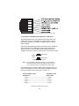
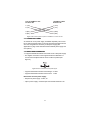
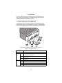
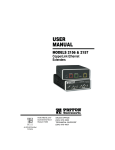
USER
MANUAL
MODELS 2156 & 2157
CopperLink Ethernet
Extenders
Part# 07M2156_2157
Doc# 032131U Rev. A
Revised 2/4/03
An ISO-9001Certified
Company
SALES OFFICE
(301) 975-1000
TECHNICAL SUPPORT
(301) 975-1007
CONTENTS
1.0
1.1
1.2
1.3
1.4
1.5
Warranty Information .................................................................
Radio and TV Interference............................................................
CE Notice......................................................................................
FCC Part 68..................................................................................
Industry Canada Notice ................................................................
Service..........................................................................................
2.0
2.1
2.2
General Information.................................................................... 6
Features........................................................................................ 6
Description.................................................................................... 6
3.0
3.1
3.2
3.5
Installation................................................................................... 8
Connecting the Twisted-Pair Line Interface.................................. 8
Line Interface—Connecting the 10/100Base-T
Ethernet Interface ......................................................................... 9
Connecting the 10/100Base-T Ethernet Port to a
Hub or PC................................................................................... 10
Connecting Power ...................................................................... 11
Power Input Connector ............................................................... 11
External AC universal power supply........................................... 11
External 48 VDC power supply................................................... 12
Console Port ............................................................................... 13
4.0
4.1
Operation................................................................................... 14
Front Panel LED Status Monitors ............................................... 14
A
A.1
A.2
A.3
A.4
A.5
A.6
A.7
A.8
Specifications ........................................................................... 15
General Characteristics .............................................................. 15
WAN Characteristics ................................................................... 15
Ethernet ....................................................................................... 15
Extension distance and rate ....................................................... 16
LED Indicators ............................................................................ 17
Power and Power Supply Specifications .................................... 17
Environmental ............................................................................. 17
Dimensions ................................................................................. 17
B
Models 2156 and 2157 Series Factory
Replacement Parts and Accessories...................................... 18
3.3
3.4
3
3
3
4
5
5
C
Models 2156 and 2157 Series Interface Pin Assignment ...... 19
C.1 10/100Base-T Interface .............................................................. 19
RJ-45 .......................................................................................... 19
C.2 CopperLink Interface .................................................................. 19
RJ-11 .......................................................................................... 19
2
1.0 WARRANTY INFORMATION
Patton Electronics warrants all Model 2156 or 2157 components to be
free from defects, and will—at our option—repair or replace the product
should it fail within one year from the first date of the shipment.
This warranty is limited to defects in workmanship or materials, and does
not cover customer damage, abuse or unauthorized modification. If this
product fails or does not performs as warranted, your sole recourse shall
be repair or replacement as described above. Under no condition shall
Patton Electronics be liable for any damages incurred by the use of this
product. These damages include, but are not limited to, the following: lost
profits, lost savings and incidental or consequential damages arising
from the use of or inability to use this product. Patton Electronics specifically disclaims all other warranties, expressed or implied, and the
installation or use of this product shall be deemed an acceptance of
these terms by the user.
Note
Conformity documents of all Patton products can be viewed
online at www.patton.com under the appropriate product page.
1.1 RADIO AND TV INTERFERENCE
The Model 2156 or 2157 generate and use radio frequency energy, and
if not installed and used properly—that is, in strict accordance with the
manufacturer’s instructions—may cause interference to radio and television reception. The Models 2156 and 2157 have been tested and found
to comply with the limits for a Class A computing device in accordance
with specifications in Subpart B of Part 15 of FCC rules, which are
designed to provide reasonable protection from such interference in a
commercial installation. However, there is no guarantee that interference
will not occur in a particular installation. If the Model 2156 or 2157 does
cause interference to radio or television reception, which can be determined by disconnecting the unit, the user is encouraged to try to correct
the interference by one or more of the following measures: moving the
computing equipment away from the receiver, re-orienting the receiving
antenna and/or plugging the receiving equipment into a different AC outlet (such that the computing equipment and receiver are on different
branches).
1.2 CE NOTICE
The CE symbol on your Patton Electronics equipment indicates that it is
in compliance with the Electromagnetic Compatibility (EMC) directive
and the Low Voltage Directive (LVD) of the European Union (EU). A Certificate of Compliance is available by contacting Technical Support.
3
1.3 FCC PART 68
The Models 2156 and 2157 are not intended to be connected to the public telephone network.
Caution
1. You are required to request service from the telephone company before
you connect the Model 2156 or 2157 to a network. When you request
service, you must provide the telephone company with the following
data.
—
The required Universal Service Order code (USOC) jack: RJ-11C
—
The make, model number, Ringer Equivalence Number (REN),
and FCC Registration number of the Model 2156 or 2157.
The REN helps you determine the number of devices you can connect to your telephone line and still have all of those devices ring
when your number is called. In most, but not all, areas, the sum of
the RENs of all devices should not exceed five (5.0). To be certain of
the number of devices you can connect to your line, you should call
your local telephone company to determine the maximum REN.
—
The Facility Interface Code: 02LS2
—
The Service Order Code(s) (SOC): 9.0F
—
REN No.: 0.2
2. Your telephone company may make changes to its facilities, equipment, operations, or procedures that could affect the proper functioning of your equipment. The telephone company will notify in
advance of such changes to give you an opportunity to maintain
uninterrupted telephone service.
3. If your Model 2156 or 2157 causes harm to the telephone network,
the telephone company may temporarily discontinue your service. If
possible, they will notify you in advance, but if advance notice is not
practical, you will be notified as soon as possible and will be
informed of your right to file a complaint with the FCC.
4. If you experience trouble with the Model 2156 or 2157, contact Patton Electronics Company for service or repairs. Repairs should be
performed only by Patton Electronics Co.
5. You are required to notify the telephone company when you disconnect the Model 2156 or 2157 from the network.
4
1.4 INDUSTRY CANADA NOTICE
NOTICE: This equipment meets the applicable Industry Canada Terminal Equipment Technical Specifications. This is confirmed by the registration number. The abbreviation IC, before the registration number signifies
that registration was performed based on a Declaration of conformity
indicating that Industry Canada technical specifications were met. It does
not imply that Industry Canada approved the equipment.
1.5 SERVICE
All warranty and non-warranty repairs must be returned freight prepaid
and insured to Patton Electronics. All returns must have a Return Materials Authorization number on the outside of the shipping container. This
number may be obtained from Patton Electronics Technical Services at:
• Telephone: +1 (301) 975-1007
• Email: [email protected]
• URL: http://www.patton.com
Technical support is available from 8 AM to 5 PM EST (8:00 to 17:00
UTC-5), Monday through Friday.
Note
Packages received without an RMA number will not be
accepted.
5
2.0 GENERAL INFORMATION
Thank you purchasing this Patton Electronics product. This product has
been thoroughly inspected and tested and is warranted for one year for
parts and labor. If questions arise while installing or using this product,
contact Technical Support at +1 (301) 975-1007.
2.1 FEATURES
• Easy-to-install Ethernet Extenders—no configuration required
• Auto-rate adaption ensures the highest rate possible for each extension distance
• Data rates to 2.3 Mbps (for Model 2156) and 4.6 Mbps (for Model 2157)
• Auto-sensing 10/100Base-T
• Extends network connections up to 30,000 ft (9,144 m) over 2-wire 24AWG unconditioned lines (see Appendix A on page 15)
• Transparent operation to higher level protocols such as TCP/IP, DECnet, NETBIOS, IPX, etc.
• Compatible with 802.1Q VLAN
• LED indicators for Power; Ethernet Link, 100Base-T Operation, Transmit,
Receive; WAN Link, Transmit, Receive
• Made in the USA
2.2 DESCRIPTION
The Patton Electronics CopperLink Ethernet Extenders provide highspeed LAN connections between peered Ethernet LANs, remote PCs, or
any other network enabled 10/100Base-T device.
Operating in pairs, a Model 2156 or 2157 can automatically forward LAN
broadcasts, multicasts, and frames across a 2-wire voice-grade twistedpair link. The data is passed transparently (unmodified) through the Ethernet Extenders. They automatically add and delete MAC addresses, only
passing packets across the CopperLink line that are meant for the remote
peered LAN.
6
Figure 1. Typical application
The 2157/L and 2157/R work together to create a transparent extension
between two peered Ethernet LANs. Figure 1 shows a typical point-topoint application.
7
3.0 INSTALLATION
Because the CopperLink Ethernet Extenders require no configuration, they
can be installed quickly. Installation consists of the following:
• Connect the line interface between the units (refer to section 3.1,
“Connecting the Twisted-Pair Line Interface” on page 8)
Note
See Figure 2 for the rear-panel connectors locations.
• Connect the Ethernet interface (refer to section 3.2, “Line Interface—
Connecting the 10/100Base-T Ethernet Interface” on page 9).
• Connect the power plug (refer to section 3.3, “Connecting Power” on
page 11).
Figure 2. CopperLink Ethernet Extender rear panel
3.1 CONNECTING THE TWISTED-PAIR LINE INTERFACE
The Models 2156 and 2157 support communication between two peer
Ethernet LAN sites over a distance greater than 30,000 ft (9,144 m) over
24 AWG (0.5 mm) twisted-pair wire.
Note
The Models 2156 and 2157 use an auto-rate adaption feature to
provide the fastest data rate possible over the wire and distance
of each Ethernet extension. The actual distance and rate
achieved for Ethernet extension may vary depending on the
environment and type/gauge of the wire used.
8
Follow the steps below to connect the CopperLink interfaces.
Note
The Model 2156 or 2157 units work in pairs. One of the units
must be a Model 2156/L (local) or 2157/L, and the other unit
must be a Model 2156/R (remote) or 2157/R.
1. To function properly, the two Ethernet Extenders must be connected
together using twisted-pair, unconditioned, dry, metal wire, between
19 (0.9mm) and 26 AWG (0.4mm). Leased circuits that run through
signal equalization equipment are not acceptable.
2. The Models 2156 and 2157 are equipped with an RJ-11 interface.
The CopperLink interfaces are a two-wire interface. Observe the signal/pin relationships on the CopperLink interface jack.
The RJ-11 connector on the CopperLink Ethernet Extender’s twisted pair
interface is polarity insensitive and is wired for a two-wire interface. The
signal/pin relationship is shown in Figure 3.
Figure 3. CopperLink Ethernet Extender (RJ-11) twisted pair line interface.
3.2 LINE INTERFACE—CONNECTING THE 10/100BASE-T
ETHERNET INTERFACE
The shielded RJ-45 port labeled Ethernet is the 10/100Base-T interface.
This port is designed to connect directly to a 10/100Base-T network.
Figure 4 shows the signal/pin relationships on this interface. You may
connect this port to another Ethernet device via a Type 4 or Type 5 cable
that is up to 328 ft (100 m) long.
9
Figure 4. CopperLink Ethernet Extender 10/100Base-T RJ-45 Connector Pinout.
Connecting the 10/100Base-T Ethernet Port to a Hub or PC
The Models 2156 and 2157 are equipped with an MDI-X switch that
enables connections to a hub (DCE) or PC (DTE) interface, thereby
elimininating confusion over whether a straight-through or crossover
cable is needed.
When using a straight-through cable for connecting to a hub, the MDI-X
switch should be in its released (DCE mode) position (see Figure 5).
When connecting to a PC, the MDI-X switch should be pushed in to
engage the crossover function so you won’t have to use a crossover cable
DTE mode
MDI-X
switch
DCE mode
Figure 5. MDI-X switch positions
Note
If you have difficulty achieving a working connection between
the CopperLink Ethernet Extender’s Ethernet port and the hub
or PC, change the position of the MDI-X switch and try again.
In its released position, the MDI-X switch enables straight-through connections (see Figure 6) or in its inserted position the MDI-X switch performs the crossover function (see Figure 7 on page 11).
2157 10/100Base-T Port
RJ-45 Pin No.
10/100Base-T Hub
RJ-45 Pin No.
1 (TX+)--------------------------------------------------1 (RX+)
2 (TX-)---------------------------------------------------2 (RX-)
3 (RX+)--------------------------------------------------3 (TX+)
6 (RX-)---------------------------------------------------6 (TX-)
Figure 6. Wiring diagram for connecting the CopperLink Ethernet Extender to a
10/100Base-T hub (MDI-X switch released)
10
2157 10/100Base-T Port
RJ-45 Pin No.
10/100Base-T DTE
RJ-45 Pin No.
1 (TX+)
1 (TX+)
2 (TX-)
2 (TX-)
3 (RX+)
3 (RX+)
6 (RX-)
6 (RX-)
Figure 7. MDI-X switch pressed in performs 10/100Base-T crossover function
3.3 CONNECTING POWER
An external AC or DC power supply is available separately. This connection is made via the barrel jack on the rear panel of the Models 2156 and
2157. No configuration is necessary for the power supply (See
Appendix B on page 18 for domestic and international power supply and
cord options).
3.4 POWER INPUT CONNECTOR
The CopperLink Ethernet Extender comes with an AC or DC power supply.
• The supplies connection to the CopperLink Ethernet Extender is a
2.5 mm barrel receptacle with the center conductor positive (see
Figure 6).
Figure 8. Power connection barrel receptacle diagram
• CopperLink Ethernet Extender’s rated voltage: 5.0 VDC
• CopperLink Ethernet Extender’s rated current: 1 A DC
External AC universal power supply
• Output from power supply: 5 VDC, 2A
• Input to power supply: universal input 100–240 VAC 50/60 Hz 0.3A
11
An approved external power supply that incorporates a
disconnect device must be used and positioned within
easy reach of the operator’s position.
Caution
Connect the equipment to a 5 VDC source that is electrically isolated from the AC source. The 5 VDC source is to
be reliably connected to earth.
Caution
External 48 VDC power supply
• Input
– Rated voltage: 36–60 VDC
– Rated current: 0.25 A DC at nominal 48 VDC
– 3-pin locking connector, 3.5 mm pitch
– Reverse polarity protection
– Transient over-voltage protection, 100 VDC at 2 ms
• Output
– Rated voltage: 5 VDC ± 5%, 5W
– Rated current; 1 A DC
– 6-inch cable terminated with 2.5 mm barrel plug, center positive
An approved external power supply that incorporates a
disconnect device must be used and positioned within
easy reach of the operator’s position.
Caution
Connect the equipment to a 36–60 VDC source that is
electrically isolated from the AC source. The 36–60 VDC
source is to be reliably connected to earth.
Caution
12
3.5 CONSOLE PORT
The Console Port is only intended for use by Patton Electronics Technical
Support technicians.
13
4.0 OPERATION
Once the CopperLink Ethernet Extenders are properly installed, they
should operate transparently. No user settings required. This section
describes reading the LED status monitors.
4.1 FRONT PANEL LED STATUS MONITORS
The Models 2156 and 2157 feature eight front-panel LEDs that monitor
power, Ethernet signals, and the CopperLink connection. Figure 9 shows
the front panel location of each LED. Table 1 describes the LED functions.
Figure 9. CopperLink Ethernet Extender standalone unit front panel
Table 1: Front panel LED description
LED
Power
WAN
Description
When lit, indicates the unit is powered on
Link
• On solid—link is connected
• Off—No signal detected
TX
Flashing—Data is being transmitted from the local unit to the
remote unit
Flashing—Data is being received at the local unit from the
remote unit
On—Ethernet is linked
On—100 Mbps Ethernet is selected
Flashing—When data is transmitted from the unit to the LAN
Flashing—When data is received from the LAN
RX
Ethernet
Link
100 M
TX
RX
14
APPENDIX A
SPECIFICATIONS
A.1 GENERAL CHARACTERISTICS
• Compact low cost plug-and-play router
• 10/100 Ethernet
• Unlimited host support
• Eight front panel LEDs indicate Power, WAN, Ethernet LAN speed and
status
• Convenient and standard RJ connectors for Ethernet and line
• External UI or 48 VDC power supply options
• Standard 1-year warranty
A.2 WAN CHARACTERISTICS
• 2.3 Mbps (Model 2156) or 4.6 Mbps speed (Model 2157)
• RJ-11 connector
• Uses two-wire unconditioned twisted-pair
A.3 ETHERNET
• Full-duplex, auto-sensing,10Base-T/100Base-TX Ethernet
• Standard RJ-45 and built-in MDI-X crossover switch
• IEEE 8021.d transparent learning bridge up to 1,024 addresses and
spanning tree
• Compatible with 802.1Q VLAN
• Addresses deleted after 5 minutes of inactivity
15
A.4 EXTENSION DISTANCE AND RATE
• 2.3 Mbps (Model 2156) or 4.6 Mbps speed (Model 2157)
• Distances up to 30,000 ft (9,144 m) on 24 AWG (0.4 mm) wire
• Auto-adjusting rate picks best rate for a given extension distance (see
tables below)
Table 2: Model 2156 Extension Distances
DSL line
rate
No Noise
26g (0.4 mm)
24g (0.5 mm)
22g (0.6 mm)
20g (0.8 mm)
19g (0.9 mm)
N
kbps
miles
km
miles
km
miles
km
miles
km
miles
km
3
6
8
12
18
24
32
36
200
392
520
776
1160
1544
2056
2312
4.4
4.0
3.8
3.5
3.0
2.8
2.5
2.3
7.0
6.6
6.2
5.6
4.9
4.6
4.0
3.8
5.7
5.4
5.1
4.6
4.0
3.7
3.3
3.1
9.4
8.8
8.3
7.5
6.4
6.1
5.3
5.0
8.0
7.5
7.1
6.0
5.2
4.9
4.2
4.0
13.1
12.3
11.6
9.8
8.4
7.9
6.9
6.6
10.3
9.7
9.2
7.8
6.7
6.4
5.6
5.3
16.8
15.8
14.9
12.7
11.0
10.3
9.0
8.6
12.1
10.8
9.7
8.8
7.5
6.7
5.9
5.6
19.7
17.5
15.8
14.3
12.3
11.0
9.6
9.1
Table 3: Model 2157 Extension Distances
DSL line
rate
No Noise
26g (0.4 mm)
24g (0.5 mm)
22g (0.6 mm)
20g (0.8 mm)
19g (0.9 mm)
N
kbps
miles
km
miles
km
miles
km
miles
km
miles
km
3
6
8
12
18
24
32
36
42
48
54
60
66
72
200
392
520
776
1160
1544
2056
2312
2696
3080
3464
3848
4232
4616
4.4
4.0
3.8
3.5
3.0
2.8
2.5
2.3
2.3
2.2
2.1
1.9
1.7
1.5
7.0
6.6
6.2
5.6
4.9
4.6
4.0
3.8
3.7
3.6
3.4
3.1
2.8
2.5
5.7
5.4
5.1
4.6
4.0
3.7
3.3
3.1
3.0
3.0
2.7
2.5
2.3
2.0
9.4
8.8
8.3
7.5
6.4
6.1
5.3
5.0
5.0
4.8
4.5
4.1
3.7
3.3
8.0
7.5
7.1
6.0
5.2
4.9
4.2
4.0
4.0
3.9
3.6
3.3
2.9
2.6
13.1
12.3
11.6
9.8
8.4
7.9
6.9
6.6
6.4
6.3
5.8
5.3
4.8
4.2
10.3
9.7
9.2
7.8
6.7
6.4
5.6
5.3
5.2
5.0
4.7
4.3
3.9
3.4
16.8
15.8
14.9
12.7
11.0
10.3
9.0
8.6
8.4
8.2
7.6
7.0
6.3
5.5
12.1
10.8
9.7
8.8
7.5
6.7
5.9
5.6
5.5
5.4
4.9
4.5
4.1
3.6
19.7
17.5
15.8
14.3
12.3
11.0
9.6
9.1
8.9
8.7
8.0
7.4
6.6
5.9
16
A.5 LED INDICATORS
• Eight LED indicators
• Power
• WAN Link, Transmit, and Receive
• Ethernet Link, 100M, Transmit, and Receive
A.6 POWER AND POWER SUPPLY SPECIFICATIONS
• Either AC or DC options are available
• Connection to the CopperLink Ethernet Extender requires +5VDC
±5% DC power (1.0A minimum). Center pin is +5V. The barrel type
plug has a 2.5/5.5/10mm I.D./O.D./shaft length dimensions
• CopperLink Ethernet Extender’s rated voltage: 5.0 VDC
• CopperLink Ethernet Extender’s rated current: 1A DC
A.7 ENVIRONMENTAL
• Temperature: 32–122°F (0–50°C)
• Relative Humidity: 5–90%, non-condensing
• Altitude: 0–15,000 ft (0–4,572 m)
A.8 DIMENSIONS
1.5H x 4.2W x 5.8D in. (3.8H x 10.6W x 14.8D cm)
17
APPENDIX B
MODELS 2156 AND 2157 SERIES FACTORY
REPLACEMENT PARTS AND ACCESSORIES
Patton Model #
Description
2156 Base Models
2156/L
CopperLink Ethernet Extender; Line: RJ-11 (Local)
2156/R
CopperLink Ethernet Extender; Line: RJ-11 (Remote)
2156-2PK
CopperLink Ethernet Extender Kit: includes one local (L) and
one remote (R) Model 2156
2157 Base Models
2157/L
CopperLink Ethernet Extender; Line: RJ-11 (Local)
2157/R
CopperLink Ethernet Extender; Line: RJ-11 (Remote)
2157-2PK
CopperLink Ethernet Extender Kit: includes one local (L) and
one remote (R) Model 2157
2156 and 2157 User Manual
07M2156_2157
User Manual
Power Supplies
08055DCUI
100–240VAC (+5V reg. DC/2A) Universal Input Adapter.
Power Cords*
0805US
American Power Cord
0805EUR
European Power Cord CEE 7
0805UK
United Kingdom Power Cord
0805AUS
Australian Power Cord
0805DEN
Denmark Power Cord
0805FR
France/Belgium Power Cord
0805IN
India Power Cord
0805IS
Israel Power Cord
0805JAP
Japan Power Cord
0805SW
Switzerland Power Cord
*Only required with optional UI power supply (08055DCUI)
18
APPENDIX C
MODELS 2156 AND 2157 SERIES INTERFACE PIN ASSIGNMENT
C.1 10/100BASE-T INTERFACE
RJ-45
• Pin 1: TX+
• Pin 2: TX• Pin 3: RX+
• Pin 6: RX• Pins 4, 5, 7, 8: no connection
C.2 COPPERLINK INTERFACE
RJ-11
• Pin 2: RING
• Pin 3: TIP
• Pins 1 & 4: no connection
19
Notes
________________________________________________________
________________________________________________________
________________________________________________________
________________________________________________________
________________________________________________________
________________________________________________________
________________________________________________________
________________________________________________________
________________________________________________________
________________________________________________________
________________________________________________________
________________________________________________________
________________________________________________________
________________________________________________________
________________________________________________________
________________________________________________________
________________________________________________________
________________________________________________________
________________________________________________________
________________________________________________________
________________________________________________________
Copyright © 2002
Patton Electronics Company
All Rights Reserved.
20