1
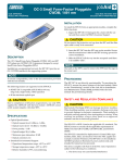
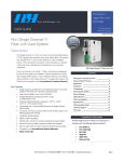
JOBAID
DDM+ HTU-CM
DDM+
HTU-CM
LED STATUS
HTU-R Options Display (“VIEW”)
● GREEN
Synchronization
✷ FLASHING ES, SES or BPV detected
● YELLOW
Loopbacks active
✷ FLASHING In-band loopbacks armed
● RED
Alarm on any HTU-C loops, HRE loops, DSX or DS1 interface
✷ FLASHING Signal Quality of 0 or No Sync on at least one loop
STATUS
CLEI:T1L3BWBA_ _
HTU-C
1246003L8
61246003L8-22B
0006
4 CHARACTER DISPLAY (FCD) OPERATION
MODE
UP = MODE
CENTER = OFF
DOWN = SELECT
SELECT
MODE
Message
Description
Settings
Default
TXLV
PRM
DS1 Transmit Level
Performance Reporting Messages
0 dB, -15 dB
NPRM, SPRM, None
0 dB
None
Parameter Settings Display (“PROV”)
Message
Description
Settings
Default
LBO
CODE
FRMG
NELB
NLBK
LBTO
CLOS
LTCH
SPWR
SALM
DSX-1 Transmit Level
Line Code
DSX-1 Framing
New England 1:6 loopback
NIU Loopback
Loopback Timeout
Customer Loss Response
Latching Loopback
Span Power
Shelf Alarm
0, 133, 266, 399, 533
AMI, B8ZS
AUTO, ESF, SF, UNF, FFFC
EN, DIS
EN, DIS
0, 120
AIS, LPBK, CDI
T1, FT1
ON, OFF
EN, DIS
0
B8ZS
ESF
DIS
EN
120
AIS
T1
ON
EN
Loopback Options Display (“LPBK”)
FCD Modes
SELECT
STATUS
R
S
2
3
2
Mode
Display
Status
STAT
Display Off
View
Provisioning
Default
Loopback
Blank
VIEW
PROV
DFLT
LPBK
HDSL loop margin, displays 1=xx or 2=xx, where xx=loop margin
0-2 marginal signal quality, 3-20 acceptable signal quality
Result after five minutes of no activity
View current parameters without changing
Set configuration options
Sets all factory defaults
Select and execute HDSL circuit loopbacks
Status/Alarm Display (“STAT”)
Select
Loopback State
Loopback Description
LPBK
HTUC
Net
CST
NONE
BLB
NET
CST
NONE
NET
CST
NONE
NET
CST
NONE
Network loopback at HTU-C
Customer loopback at HTU-C
No active loopback
Bilateral loopback at HTU-R
Network loopback at HTU-R
Customer loopback at HTU-R
No active loopback
Network loopback at HRE1
Customer loopback at HRE1
No active loopback
Network loopback at HRE2
Customer loopback at HRE2
No active loopback
HTUR
HRE1
HRE2
Message Condition
HER1
HER2
LERR
RERR
LBPV
RBPV
LOS1
LOS2
LLOS
RLOS
ARM
C A U T I O N !
Function
Mode
CRC error detected on HDSL Loop 1
CRC error detected on HDSL Loop 2
Frame bit error (SF Mode) or CRC error (ESF Mode) detected locally at DSX-1 of the HTU-C
Frame bit error (SF Mode) or CRC error (ESF Mode) detected locally at DS-1 of the HTU-C
Bipolar Violation (BPV) detected locally at DSX-1 of the HTU-C
BPV detected locally at DS-1 of the HTU-R
No synchronization of HTU-C and HTU-R on Loop 1
No synchronization of HTU-C and HTU-R on Loop 2
DSX signal is absent from the network interface or is of a format which does not
match the provisioning of the HDSL circuit
DS1 signal is absent from the network interface or is of a format which does not
match the provisioning of the HDSL circuit
The loopback arming sequence has been detected
WARRANTY
Carrier Network products manufactured by ADTRAN and supplied under Buyer’s
order for use in the U.S. is ten (10) years. For a complete copy of ADTRAN’s U.S.
Carrier Network Equipment Warranty: (877) 457-5007, Document 414.
COMPLIANCE CODES
This product is intended for installation in restricted access locations only and in
equipment with a Type “B” or “E” installation code.
Input current at maximum load is 0.7 A at –48 VDC. Maximum output at over current
condition is 165 mA at –190 VDC.
CODE
IN OUT
Installation Code (IC)
A
–
Telecommunication Code (TC)
–
X
Power Code (PC)
F
C
SUBJECT TO ELECTROSTATIC DAMAGE
OR DECREASE IN RELIABILITY.
HANDLING PRECAUTIONS REQUIRED.
■ For a complete Installation and Maintenance Practice: (877) 457-5007, Document #455. Please have your fax number available. ■
PRICING AND AVAILABILITY 800.827.0807
TECHNICAL SUPPORT 800.923.8726
RETURN FOR REPAIR 256.963.8722
www.adtran.com
TURN-UP & TROUBLESHOOTING GUIDE
INSERTION LOSS MEASUREMENTS
HTU-C
VMDF
HRE 1
HRE2
HTU-R
HTU-C
Frequency
(kHz)
HTU-R
1246003L8
Maximum
Loss Data (dB)
1246026L4
H
D
S
L
LP1
LP2
DS1
ALM
ESF
(YEL)
SF
(GRN)
B8ZS
AMI
LLB
RLB
(YEL)
(YEL)
(GRN)
(GRN)
MODE
LOC
10000
50000
100000
150000
196000
200000
250000
325000
15.00
25.50
30.00
32.75
35.00
35.25
37.50
42.00
LBK
SELECT
REM
STATUS
B
R
G
R
S
2
3
2
A
t-t Voltage
Circuit with 2 HREs (open at frame)
185 - 190
Circuit with 0 or 1 HRE (open at frame) 145 - 150
HTU-C / HTU-R
145 - 150
HTU-C / HRE1 / HTU-R
130 - 135
HTU-C / HRE 2 / HTU-R
185 - 190
NOTE: If your TIMs is unable to transmit 200 kHz tone, set
the TIMs to one of the frequencies shown above and
compare the received signal to the maximum loss at
that frequency.
TX
M
O
N
RX
R
S
2
3
2
B
t-t Voltage
N/A
N/A
145 - 150
110 - 135
160 - 185
C
t-t Voltage
N/A
N/A
130 - 145
110 - 135
160 - 185
D
t-t Voltage
N/A
N/A
N/A
N/A
140 - 185
E
t-t Voltage
N/A
N/A
N/A
N/A
140 - 185
F
t-t Voltage
N/A
N/A
125 - 130
100 - 135
130 - 185
NOTE: All measurements taken with HTU-C installed. With the HTU-C unseated or with protector removed at VMDF, t-r resistance will be cable resistance plus 3 ohms
(for either HRE or HTU-R).
wiring problem or a B8ZS/AMI mismatch between the HTU-R and the customer equipment. This
is not an indication of problems on the HDSL loops.
Turn-up Guide
1. Set option switches according to specific circuit design
2. Install HTU-C and HTU-R
3. The status LED should be green, no alarm indications on the four-character display (FCD) and
synchronization has occurred
(a) HTU-C will display LLOS if not connected to network (no DSX present; LED will be solid red).
(b) HTU-R will have red ALM LED if customer not connected. LP1, LP2, line coding (B8ZS or
AMI) and framing (ESF or SF) (if not UNFR) LEDs should be illuminated.
4. If Status LED is green:
(a) Verify that the signal quality is the same on each loop. Ensure signal quality indicators do not
fluctuate.
(b) Verify that the loop loss is within design limits. If there is a difference of more than 1 dB
between the two loops, a problem exists with the cable pairs.
(c) If errors occur, use the Current System Status and Performance History screens to determine
where they are occuring. See Troubleshooting Guide.
5. If everything checks out, proceed with BERT testing.
Troubleshooting Guide
The HTU-C status LED is flashing green and the FCD indicates "LERR," "HER1," "HER2" or "LBPV"
but no errors are indicated by the HTU-R
■ A BPV, Frame error (SF) or CRC error (ESF) has been detected at the DSX-1 interface. Possible network or wiring problem between the HTU-C and the DSX. This is not an indication of problems on
the HDSL loops.
The HTU-R DS1 LED is Flashing, but no Errors are Indicated by the HTU-C
■ A BPV, Frame Error (SF) or CRC Error (ESF) has been detected at the DS1 interface. This indicates a
The HTU-R has Power, but LP1 and LP2 LEDs are Dark. The Unit cannot Sync with the HTU-C
■ Simplex power for powering the HTU-R can be passed over cable pairs that contain load coils or
that are too long for HDSL synchronization. Using a TIMS, verify the circuit is within design limits.
■
The HTU-R will power up as long as there is at least one good conductor on each loop. To test,
remove the protector plug at the MDF and measure t-r resistance to the HTU-R on both loops.
The HTU-R will place a 3 ohm short between t-r on both loops. An extremely high impedance
indicates an open conductor. An extremely low reading on one loop may indicate a t-r short in
the field. In the field, measure t-t and t-r voltage with the HTU-C installed and compare to the
chart above. If these voltages are not present, open pairs or mis-wiring is indicated. As with other
circuits, standard resistance measurements between each conductor and ground should also be
used to test for a grounded conductor.
■
A high resistance open which degrades to the point that it causes the circuit to lose sync can
be “resealed” by reseating the HTU-C. Test the cable pairs before reseating the HTU-C.
Running Excessive Errors on the Loop
■
Measure t-r resistance as described above. If the pairs are unbalanced by more than 4 ohms, or
a measurement varies a great deal, this could indicate a high resistance open or an intermittent
fault on the loop with the higher measurement. A TDR is typically required to locate this splice
for repair.
■
Excessively long bridged taps can also cause errors. Check the records and/or use a TDR to verify
the location and length of bridged taps.
■
Using ADTRAN’s “Performance History” screen, it is often possible to see that many more errors
are being received on a particular loop or at a particular unit. The fault will typically be very close
to the unit receiving the most errors.
No Power at the HTU-R
■
This could be caused by a loop with two open conductors. Measure t-r resistance from the MDF
to the HTU-R or use the voltage chart to see which pair is open.