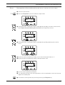
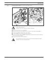
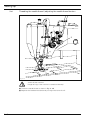
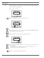
1
®
Industrial
1122
1122-G
INSTRUCTION MANUAL
1122-720/02
1122-G-720/02
This instruction manual applies to machines from the
following serial numbers onwards:
# 6 001 000
296-12-18 581/002
Betriebsanleitung engl. 06.09
This Instruction Manual is valid for all models and subclasses listed in the
chapter "Specifications ".
The adjustment manual for the machines can be downloaded free of charge
from the internet address
www.pfaff-industrial.com/pfaff/de/service/downloads
As an alternative to the internet download the adjustment manual can also be
ordered in book form under part no. 296-12-18 582/002.
The reprinting, copying or translation of PFAFF Instruction Manuals, whether in whole or
in part, is only permitted with our previous authorization and with written reference to the
source.
PFAFF Industriesysteme
und Maschinen AG
Hans-Geiger-Str. 12 - IG Nord
D-67661 Kaiserslautern
Contents
Contents ................................................................................. Chapter - Page
1
1.01
1.02
1.03
1.04
1.05
1.05.01
1.05.02
1.06
Safety ........................................................................................................................... 1 - 1
Directives ...................................................................................................................... 1 - 1
General notes on safety ................................................................................................ 1 - 1
Safety symbols ............................................................................................................. 1 - 2
Important points for the user ........................................................................................ 1 - 2
Operating and specialist personnel ............................................................................... 1 - 3
Operating personnel ...................................................................................................... 1 - 3
Specialist personnel ...................................................................................................... 1 - 3
Danger .......................................................................................................................... 1 - 4
2
Proper use.................................................................................................................... 2 - 1
3
Specifications .............................................................................................................. 3 - 1
4
Disposal of machine ................................................................................................... 4 - 1
5
5.01
5.02
5.03
5.04
Transport, packaging and storage ............................................................................. 5 - 1
Transport to the customer ............................................................................................ 5 - 1
Storage ......................................................................................................................... 5 - 1
6
Explanation of the symbols ........................................................................................ 6 - 1
7
7.01
7.02
7.03
7.04
7.05
7.06
7.07
7.08
7.09
7.10
7.10.01
7.10.02
Controls ....................................................................................................................... 7 - 1
On/off switch ................................................................................................................ 7 - 1
8
8.01
8.01.01
8.01.02
8.01.03
8.01.04
8.01.05
Transport within the customer’s premises ................................................................... 5 - 1
Disposal of the packaging ............................................................................................. 5 - 1
Pedal ............................................................................................................................. 7 - 1
Lever for lifting the presser foot .................................................................................... 7 - 2
Knee lever ..................................................................................................................... 7 - 2
Key on the machine head (only on machines with backtacking device -911/93) ........... 7 - 3
Reverse feed key .......................................................................................................... 7 - 3
Stitch length adjustment wheel .................................................................................... 7 - 4
Switching needles (only on machines with disengagable needles -720/02) .................. 7 - 4
Switch for the thread wiper (only on machines with thread wiper -909/93) .................. 7 - 5
Control panel (only on machines with Quick-motor) ...................................................... 7 - 6
Screen displays ............................................................................................................. 7 - 6
Function keys ................................................................................................................ 7 - 6
Installation and commissioning ................................................................................. 8 - 1
Installation ..................................................................................................................... 8 - 1
Adjusting the table height ............................................................................................. 8 - 1
Assembling the oil pan .................................................................................................. 8 - 2
Mounting the sewing head ........................................................................................... 8 - 2
Assembling the motor (only on machines with Quick-motor) ........................................ 8 - 3
Tightening the V-belt ..................................................................................................... 8 - 3
Contents
Contents ................................................................................. Chapter - Page
8.01.06
8.01.07
8.01.08
8.01.09
8.02
8.02.01
8.02.02
8.03
8.04
Mounting the bottom V-belt guard ................................................................................ 8 - 4
Mounting the top V-belt guard ...................................................................................... 8 - 5
Fitting the reel stand ..................................................................................................... 8 - 5
Connecting the plug-in connections and earth cables ................................................... 8 - 6
Commissioning ............................................................................................................. 8 - 7
Switching on the machine and executing the pulley function ....................................... 8 - 7
Basic position of the machine drive unit (only on machines with Quick motor)............. 8 - 8
Table top cutout ............................................................................................................ 8 - 9
Mounting the table top .................................................................................................. 8 - 10
9
9.01
9.02
9.03
9.04
9.05
9.06
9.07
9.08
Setting up .................................................................................................................... 9 - 1
Inserting the needle ...................................................................................................... 9 - 1
10
10.01
10.02
10.03
10.04
10.05
10.06
10.07
Care and maintenance .............................................................................................. 10 - 1
Maintenance intervals ................................................................................................. 10 - 1
11
Winding the bobbin thread ............................................................................................ 9 - 2
Changing the bobbin on the PFAFF 1122-720/02 .......................................................... 9 - 3
Changing the bobbin (on machines with drop-in hook) .................................................. 9 - 4
Threading the needle thread / adjusting the needle thread tension ............................... 9 - 5
Adjusting the stitch length ............................................................................................ 9 - 6
Entering start and end backtacks (only on machines with Quick motor) ....................... 9 - 6
Setting the stitch counting function for monitoring the bobbin thread .......................... 9 - 7
Cleaning the machine .................................................................................................. 10 - 1
Cleaning the hook compartment ................................................................................. 10 - 2
Oiling the machine ...................................................................................................... 10 - 3
Oiling the hook race .................................................................................................... 10 - 4
Oiling the head parts ................................................................................................... 10 - 4
Oil disposal .................................................................................................................. 10 - 5
Wearing parts ............................................................................................................ 11 - 1
Safety
1
Safety
1.01
Directives
This machine is constructed in accordance with the European regulations contained in the
conformity and manufacturer’s declarations.
In addition to this Instruction Manual, also observe all generally accepted, statutory and other
regulations and legal requirements and all valid environmental protection regulations!
The regionally valid regulations of the social insurance society for occupational accidents or
other supervisory organizations are to be strictly adhered to!
1.02
General notes on safety
● This machine may only be operated by adequately trained operators and only after having
completely read and understood the Instruction Manual!
● All Notes on Safety and Instruction Manuals of the motor manufacturer are to be read
before operating the machine!
● The danger and safety instructions on the machine itself are to be followed!
● This machine may only be used for the purpose for which it is intended and may not be
operated without its safety devices. All safety regulations relevant to its operation are to
be adhered to.
● When exchanging sewing tools (e.g. needle, roller presser, needle plate and bobbin),
when threading the machine, when leaving the machine unattended and during
maintenance work, the machine is to be separated from the power supply by switching
off the On/Off switch or by removing the plug from the mains!
● Everyday maintenance work is only to be carried out by appropriately trained personnel!
● Repairs and special maintenance work may only be carried out by qualified service staff
or appropriately trained personnel!
● Work on electrical equipment may only be carried out by appropriately trained personnel!
● Work is not permitted on parts and equipment which are connected to the power supply!
The only exceptions to this rule are found in the regulations EN 50110.
● Modifications and alterations to the machine may only be carried out under observance of
all the relevant safety regulations!
● Only spare parts which have been approved by us are to be used for repairs! We
expressly point out that any replacement parts or accessories which are not supplied by
us have not been tested and approved by us. The installation and/or use of any such
products can lead to negative changes in the structural characteristics of the machine.
We are not liable for any damage which may be caused by non-original parts.
1-1
Safety
1.03
Safety symbols
Danger!
Points to be observed.
Danger of injury for operating and specialist personnel!
Caution
Do not operate without finger guard and safety devices.
Before threading, changing bobbin and needle, cleaning
etc. switch off main switch.
I
1.04
Important points for the user
● This Instruction Manual is an integral part of the machine and must be available to the
operating personnel at all times.
● The Instruction Manual must be read before operating the machine for the first time.
● The operating and specialist personnel is to be instructed as to the safety equipment of
the machine and regarding safe work methods.
● It is the duty of the user to only operate the machine in perfect running order.
● It is the obligation of the user to ensure that none of the safety mechanisms are removed
or deactivated.
● It is the obligation of the user to ensure that only authorized persons operate and work on
the machine.
Further information can be obtained from your PFAFF agent.
1-2
Safety
1.05
Operating and specialist personnel
1.05.01
Operating personnel
Operating personnel are persons responsible for the equipping, operating and cleaning of the
machine as well as for taking care of problems arising in the sewing area.
The operating personnel is required to observe the following points and must:
● always observe the Notes on Safety in the Instruction Manual!
● never use any working methods which could adversely affect the safety of the machine!
● not wear loose-fitting clothing or jewelery such as chains or rings!
● also ensure that only authorized persons have access to the potentially dangerous area
around the machine!
● always immediately report to the person responsible any changes in the machine which
may limit its safety!
1.05.02
Specialist personnel
Specialist personnel are persons with a specialist education in the fields of electrics,
electronics and mechanics. They are responsible for the lubrication, maintenance, repair and
adjustment of the machine.
The specialist personnel is obliged to observe the following points and must:
● always observe the Notes on Safety in the Instruction Manual!
● switch off the On/Off switch before carrying out adjustments or repairs, and ensure that
it cannot be switched on again unintentionally!
● wait until the luminous diode on the control box is no longer blinking or on before
beginning adjustment or repair work.
● never work on parts which are still connected to the power supply! Exceptions are
explained in the regulations EN 50110.
● replace the protective coverings and close the electrical control box afer all repairs or
maintenance work!
1-3
Safety
1.06
Danger
A working area of 1 meter is to be kept free both in front of and behind the
machine while it is in operation so that it is always easily accessible.
Never reach into the sewing area while sewing! Danger of injury by the needle!
Never leave objects on the table while adjusting the machine settings! Objects
can become trapped or be slung away! Danger of injury!
When using mechanically operated clutch motors without an operating lock,
wait until the motor has stopped! Danger of injury!
1
3
2
4
Fig. 1 - 01
Do not operate the machine without its take-up lever guard 1!
Danger of injury due to the motion of the take-up lever!
Do not operate the machine without the finger guard 2!
Danger of injury by the needle!
If an external motor is used, do not operate the machine without the belt
guards 3 and 4!
Danger of injury by the drive belt!
1-4
Proper use
2
Proper use
The PFAFF 1122 is a two-needle, lockstich sewing machine with needle feed and vertical
hook.
The PFAFF 1122-G is a two-needle, lockstich sewing machine with needle feed and large
vertical hook.
The PFAFF 1122-720/.. is a two-needle, lockstich sewing machine with needle feed, vertical
hook, and disengagable needles.
The PFAFF 1122-G-720/.. is a two-needle, lockstich sewing machine with needle feed, large
vertical hook and disengagable needles.
All machines are used for sewing lockstitch seams in the textile and leather industry.
Any and all uses of this machine which have not been approved of by the
manufacturer are considered to be inappropriate! The manufacturer cannot be
held liable for any damage caused by the inappropriate use of the machine!
The appropriate use of the machine includes the observance of all operational,
adjustment, maintenance and repair measures required by the manufacturer!
2-1
Specifications
3
Specifications
3.01
General specifications ▲
Stitch type: .................................................................................................. 310 (lockstitch)
Needle system: ........................................................................................................... DPx5
Thread size: .................................................................................................................. 30/3
(synthetic or similar sizes of other thread types)
Needle size in 1/100 mm:
Version A: ........................................................................................................... 60 - 70 Nm
Version B: ......................................................................................................... 80 - 100 Nm
Version C: ...................................................................................................... 110 – 140 Nm
Presser foot clearance: ....................................................................................... 7 - 13 mm
Clearance width: .................................................................................................... 245 mm
Clearance height: ..................................................................................................... 98 mm
Max. stitch length:
1122 Version A and B: ................................................................................................ 4 mm
1122 and 1122-720/02 Version A, B and C: ................................................................ 5 mm
1122-G and 1122-G-720/02 Version B and C: ............................................................. 7 mm
Max. speed:
1122 Version A and B: .......................................................................................... 3500 spm
1122 Version C and 1122-G: ................................................................................. 3000 spm
1122-720/02 and 1122-G-720/02: ......................................................................... 3000 spm
Motor data: ............................................................................ see motor specification plate
Noise data 1122 and 1122-720/02:
Emission sound level at workplace
at a speed of 2400 spm: .......................................................................... Lpa = 80.0 dB(A) ■
(Noise measurement in accordance with DIN 45 635-48-B-1, ISO 11204, ISO 3744, ISO 4871)
Noise data 1122-G and 1122-G-720/02:
Sound transmission level at a speed of 2400 spm: .................................. Lpa = 93.5 dB(A) ■
(Noise measurement in accordance with DIN 45 635-48-B-1, ISO 11204, ISO 3744, ISO 4871)
Sewing head dimensions:
Length: ...................................................................................................... approx. 490 mm
Width: ....................................................................................................... approx. 210 mm
Height: ...................................................................................................... approx. 330 mm
Net weight of sewing head: ........................................................................ approx. 44.5 kg
Gross weight of sewing head (with packaging): ....................................... approx. 53,0 kilos
Packaging dimensions (sewing head only):
L x W x H: ............................................................................. approx. 635 x 295 x 608 mm
▲
■
3-1
Subject to alterations
KpA = 2,5 dB
Specifications
3.02
Versions and subclasses
Versions
Version A: ..................................................................................... for sewing fine materials
Version B: .................................................................. for sewing medium-weight materials
Version C: .................................................................... for sewing medium-heavy materials
Attachments:
Subclass -900/93: ........................................................................................ Thread trimmer
Subclass -909/93: ............................................................................................ Thread wiper
Subclass -911/93: .................................................................................. Backtacking device
3-2
Disposal of machine
4
Disposal of machine
● The proper disposal of the machine is the responsibility of the customer.
● The materials used in the machines are steel, aluminium, brass and various plastics.
The electrical equipment consists of plastics and copper.
● The machine is to be disposed of in accordance with the locally valid environmental
protection regulations. If necessary, a specialist is to be commissioned.
Special care is to be taken that parts soiled with lubricants are separately
disposed of in accordance with the locally valid pollution control regulations!
4-1
Transport, packaging and storage
5
Transport, packaging and storage
5.01
Transport to the customer’s premises
The machines are delivered completely packed.
5.02
Transport within the customer’s premises
The manufacturer bears no liability for transport within the customer’s premises or to the individual locations of use. Make sure that the machines are always transported upright.
5.03
Disposal of the packaging
The packaging of these machines consists of paper, cardboard and VCE fiber. The proper
disposal of the packaging is the responsibility of the customer.
5.04
Storage
The machine can be stored for up to 6 months if not in use. During this time it should be
protected from dust and moisture.
For longer storage the individual parts of the machine, especially the moving parts, must be
protected from corrosion, e.g. by a film of oil.
5-1
Explanation of the symbols
6
Explanation of the symbols
In the following section of this Instruction Manual, certain tasks or important pieces of
information are accentuated by symbols.
The symbols used have the following meanings:
Note, information
Cleaning, care
Lubrication, greasing
Servicing, repairing, adjustment, maintenance
(only to be carried out by specialist personnel)
6-1
Controls
7
Controls
7.01
On/off switch
● Switch the machine on or off by turning
main switch 1.
The switch in the illustration can
be found on machines with Quick
motors. When other motors are
used, the switch may not look
the same.
1
Fig. 7 - 01
7.02
Pedal
0
0
=
Machine stop
+1
=
Sew
-1
=
Raise presser foot (for
machines with -910/93)
-2
=
Trim thread
(for machines with -900/93)
+1
Other pedal functions can be
found in the Motor Instruction
Manual.
-1
Fig. 7 - 02
-2
7-1
Controls
7.03
Lever for lifting the presser foot
● The presser foot is raised by turning
lever 1.
1
Fig. 7 - 03
7.04
109-070
Knee lever
● By pressing the knee lever 1 in the
direction of the arrow, the presser foot is
raised.
1
109-005
Fig. 7 - 04
7-2
Controls
7.05
Key on the machine head (only on machines with backtacking device -911/93)
● If key 1 is pressed during the sewing
operation, the machine switches to
reverse sewing.
1
Fig. 7 - 05
7.06
Reverse feed key
● If key 1 is pressed during the sewing
operation, the machine switches to
reverse sewing.
1
Fig. 7 - 06
7-3
Controls
7.07
Stitch length adjustment wheel
● Set the required stitch length by turning
adjustment wheel 1.
1
Fig. 7 - 07
7.08
Switching needles (only on machines with disengagable needles -720/02)
● When lever 1 is adjusted, the desired
needle bar is disengaged.
Position "R" = right needle off
Position "L" = left needle off
● To release the lock on the needle bar,
press key 2.
1
Before operating lever 1 or
key 2, we recommend stopping
the machine and raising the
take-up lever.
2
When sewing with one needle
bar disengaged, the maximum
Fig. 7 - 07
7-4
speed should not exceed 1000
spm.
Controls
7.09
Switch for the thread wiper (only on machines with thread wiper -909/93)
● The thread wiping function is switched
on or off by pressing switch 1.
Position "0" = off
Position "I" = on
1
Fig. 7 - 08
109-062
7-5
Controls
7.10
Control panel (only on machines with Quick-motor)
2
4
1
3
SPEED
TE
ERROR
5
5
5
A
B
C
5
D
The control panel consists of display 1 and the function keys described below. The display 1
consists of a single-line alpha-numerical, 7 segment LCD display with 8 symbols. The
texts 2, located above and next to the LCD display, show the respective status of the
function keys and the operating status of the machine. The control panels switches on all
LCD-segments and the horn automatically for a short time during the power-on phase, after
which the lettering PFAFF appears on the display, until the higher-ranking control unit sends
commands to the control panel.
The function keys are located around the display 1. They are foil-packed without permanent
marking and without contact signal. Fixed functions are allocated to the keys, see Chapter
7.10.02 Function keys.
7.10.01
Screen displays
● Activated functions are displayed with a triangular marking 3 below or next to the
respective function key.
● In the sewing mode all relevant sewing data is displayed and can be changed directly,
depending on the status of the machine, see also Chapter 10 Sewing.
● During the parameter input the selected parameter number with the corresponding value
is displayed, see Chapter 12.08.02 Example of a parameter input.
7.10.02
Function keys
The function keys described below are used basically to switch machine functions on and
off.
Each time a key is pressed, this must be confirmed by at least one beep tone. Irrespective
of the machine mode a double beep signal is given if invalid keys are pressed or maximum
values reached.
If a corresponding value has to be set for the activated function, this is carried out with the
corresponding +/- key. By pressing and holding the corresponding +/- key, the relevant
numerical value 4 is changed slowly to begin with. If the corresponding +/- key is held down
longer, the values change more quickly.
7-6
Controls
Start backtacks
● If this key is pressed, the backtacks at the beginning of the seam (start backtacks) are
switched on or off. The number of forward stitches (A) or reverse stitches (B) for the start
backtacks can be changed by pressing the +/- key underneath. To convert from double
backtack to single backtack set the number of stitches for the corresponding seam
section at zero.
End backtacks
● If this key is pressed, the backtacks at the end of the seam (end backtacks) are switched
on or off. The number of reverse stitches (C) or forward stitches (D) can be changed by
pressing the +/- key underneath. To convert from double backtack to single backtack set
the number of stitches for the corresponding seam section at zero.
Needle position
● If this key is pressed the "needle raised after sewing stop" function is switched on or off.
When the function is switched on, the needle positions at t.d.c. after sewing stops.
Foot position after stop
● If this key is pressed the "foot raised after sewing stop" function is switched on or off.
When the function is switched on, the presser foot is raised after sewing stops.
Foot position after trimming
● If this key is pressed the "foot raised after thread trimming" function is switched on or off.
When the function is switched on, the presser foot is raised after thread trimming.
Thread trimmer
● If this key is pressed the thread trimming function is switched on or off.
Darning program
● If this key is pressed the darning program function is switched on or off. The counted
seam function is switched off automatically.
Counted seam
● If this key is pressed the counted seam function is switched on or off. The darning
program function is switched off automatically.
TE/Speed
● If this key is pressed once the speed limit for the sewing mode is activated.
● If this key is pressed twice (within 5 seconds) the machine changes from sewing to input
mode.
7-7
Installation and commissioning
8
Installation and commissioning
The machine must only be installed and commissioned by qualified personnel!
All relevant safety regulations must be strictly adhered to!
If the machine is delivered without a table, be sure to use a stand and table top
that can hold the weight of the machine with its motor.
It is very important to ensure that the stand of the machine is firm and steady,
also during sewing.
8.01
Installation
The site where the machine is installed must be provided with suitable connections for
electric current.
It must be ensured that the standing surface of the machine site is firm and horizontal, and
that sufficient lighting is provided for.
For packing and transportation reasons the table top is in the lowered position.
The table height is adjusted as described below.
8.01.01
Adjusting the table height
1
1
2
Fig. 8 - 01
● Loosen screws 1 and 2 and set the table height as required.
● Firmly tighten screw 1.
● Set the required pedal position and tighten screw 2.
8-1
109-010
Installation and commissioning
8.01.02
Assembling the oil pan
2
1
3
4
4
Fig. 8 - 02
●
●
●
●
8.01.03
Insert rubber support 1.
Insert bearing bushes 2 and fasten with nails.
Place oil pan 3 in the table-top opening.
Insert rubber pad 4 and fasten with nails.
Mounting the sewing head
● Place both hinges 1 in the appropriate
holes in the bedplate of the sewing head
and screw tight.
● Place the sewing head with hinges 1 into
the back rubber pads.
1
Fig. 8 - 03
8-2
Installation and commissioning
8.01.04
Assembling the motor (only on machines with Quick-motor)
1
2
4
3
109-001
Fig. 8 - 04
● Assemble motor mounting 1, motor 2, belt guard support 3 and belt pulley 4 as shown in
Fig. 8-04.
8.01.05
Tightening the V-belt
● Fit the V-belt.
● Loosen nut 1 and tighten the V-belt by
turning motor mounting 2.
● Tighten nut 1.
1
2
109-020
Fig. 8 - 05
8-3
Installation and commissioning
8.01.06
Mounting the bottom V-belt guard
4
2
3
2
1
Fig. 8 - 06
109-071
● Loosen screws 2 and adjust belt guard support 1 so that the motor pulley and V-belt run
freely.
● Tighten screws 2.
● Fasten belt guard 3 with screw 4.
Fig. 8-06 shows a Quick-motor. If a different motor is used, follow the
instructions of the Motor Instruction Manual.
8-4
Installation and commissioning
8.01.07
Mounting the top V-belt guard
5
3
2
1
7
6
7
5
4
5
Fig. 8 - 07
●
●
●
●
8.01.08
Take out screws 1 and 2 and remove balance wheel cover 3.
Fasten belt guard 4 with screws 5.
Fasten belt guard 6 with screws 7.
Reattach cover 3 with screws 1 and 2.
Fitting the reel stand
● Fit the reel stand as shown in Fig. 8 - 08.
● Afterwards insert the stand in the hole in
the table top and secure it with nuts provided.
Fig. 8 - 08
8-5
Installation and commissioning
8.01.09
Connecting the plug-in connections and earth cables
B
X1
A
3
X2
X4
X3
1
2
X5
Fig. 8 - 09
●
●
●
●
●
Connect the plug connections leading off the machine to adapter X5.
Connect all plugs as labelled to the control box 1.
Screw the earth cable from the sewing head and the main switch to earth point A.
Connect earth point A to earth point B with earth cable 2.
Screw the earth cable 3 from the motor to earth point B.
8-6
Installation and commissioning
8.02
Commissioning
Before commissioning the machine, clean it thoroughly, fill the oil pan with oil
and adjust the oil level, see Chapter 10 Care and Maintenance!
● Examine the machine, in particular the electric cables, for any damage.
Have qualified personnel check whether the machine can be operated with the
available voltage and whether it is connected properly. If there are any
irregularities do not operate the machine!
The machine may only be connected to an earthed socket!
When commissioning the machine or after a long period of non-operation,
operate the machine with max. 2000 spm for the first 10 minutes! Danger of
damage to the machine!
● When the machine is running, the balance wheel must turn towards the operator. If this
is not the case, have the motor adjusted by qualified personnel, see the motor operating
instructions.
8.02.01
Switching on the machine and executing the pulley function
(only on machines with Quick motor)
● Switch the machine on as described in Chapter 7.01 Main switch.
When the machine is switched on for the first time, the text "pulley" appears on the display
pulley
● Operate the pedal briefly (sewing).
The machines begins to run slowly, ascertains the transmission ratio between motor and
machine and stops running after about 2 revolutions.
If the pulley function does not appear after the machine has been switched on
for the first time, or if the machine has an undefined position, a master reset
must be carried out, see Chapter 12.10 Cold start in the adjustment manual.
8-7
Installation and commissioning
8.02.02
Basic position of the machine drive unit (only on machines with Quick motor)
● Switch on the machine.
2x
● Press the TE/speed key twice to select the input mode.
TE
100
on
● Select parameter "798" by pressing the corresponding +/- key, and select service level C,
see Chapter 12.08.01 Selecting the user level in the adjustment manual.
TE
798
11
C
● Select parameter "799" by pressing the corresponding +/- key (selecting the machine
class).
TE
799
1
C
● By pressing the corresponding +/- key, set the value for the parameter at "1".
● By pressing the corresponding +/- key, select parameter "700".
TE
700
0
B
● Sew one stitch by operating the pedal.
● Turn the balance wheel in the sewing direction until the needle point is level with the top
edge of the needle plate.
● Conclude the sewing motor adjustment by pressing the TE/speed key.
8-8
Installation and commissioning
8.03
8-9
Table top cutout.
Controlbox P 40 ED
Drillholes for fastening
the motor
(Screwed inserts M8 x 30 )
Mounting the table top
View:
from the lower side
Speedcontrolunit
8.04
Stand Position
906-3550-005/895
Installation and commissioning
8 - 10
Setting up
9
Setting up
All instructions and regulations in this instruction manual must be observed.
Special attention must be given to all safety regulations!
All setting-up work must only be done by personnel with the necessary
training. For all setting-up work the machine must be isolated from its power
supply by turning off the on/off switch or removing the machine plug from the
electric power socket!
9.01
Inserting the needle
On machines without needle switch-off
On machines with needle switch-off -720/02
1
1
Fig. 9 - 01
1
1
Fig. 9 - 02
Switch off the machine!
Danger of injury if the machine is started accidentally!
Only use needles from the system intended for the machine, see Chapter 3
Specifications.
● Raise the needle bar and loosen screws 1.
● Insert the needle as far as possible (the long groove of the left needle must be pointing to
the right and the long groove of the right needle to the left).
● Tighten screws 1.
The selection of the needles depends on the machine version and the threads
and material being used, see Chapter 3 Specifications.
9-1
Setting up
9.02
Winding the bobbin thread
2
1
3
4
Fig. 9 - 03
109-072
● Place the empty bobbin 1 on bobbin winder spindle 2.
● Thread the thread as shown in Fig. 9-03 and wind it around the bobbin a few times in a
clockwise direction.
● Adjust the thread tension by turning knurled screw 3.
● Push lever 4 in the direction of the arrow until it locks into place.
The bobbin is filled during sewing.
9-2
Setting up
9.03
Changing the bobbin on the PFAFF 1122-720/02
1
2
3
Fig. 9 - 04
Fig. 9 - 05
109-023
Switch off the machine!
Danger of injury if the machine is started accidentally!
Removing the bobbin case
● Raise the take-up lever to its top position.
● Open the cover of the hook compartment, raise latch 1 and remove bobbin case 2.
Threading the bobbin case
● Thread the bobbin as shown in Fig. 9-05.
● When the thread is drawn, the bobbin must turn in the direction of the arrow.
● With screw 3 adjust the bobbin thread tension so that the material does not pucker and
the thread does not break.
Inserting the bobbin case
● Insert the bobbin case 2 in such a way, that you can feel it click into place.
● Press down latch 1 and close the cover of the hook compartment.
Do not operate the machine with the cover of the hook compartment open!
Danger of injury from the rotating hook!
9-3
Setting up
Changing the bobbin (on machines with drop-in hook)
3
1
4
2
Fig. 9 - 06
109-095
5
109-061
9.04
Fig. 9 - 07
Switch off the machine!
Danger of injury if the machine is started accidentally!
Raise the take-up lever to its top position.
Open the cover of the hook compartment, raise latch 1 and remove empty bobbin 2.
Insert the full bobbin and press down latch 1 again.
Guide the bobbin thread under spring 4 through slot 3.
By turning screw 5 adjust the bobbin thread tension so that the material does not pucker
and the thread does not break.
● Close the cover of the hook compartment.
●
●
●
●
●
Do not operate the machine with the cover of the hook compartment open!
Danger of injury from the rotating hook!
9-4
Setting up
9.05
Threading the needle thread / adjusting the needle thread tension
1
2
Fig. 9 - 08
Switch off the machine!
Danger of injury if the machine is started accidentally!
● Thread the needle thread as shown in Fig. 9 - 08.
● Regulate the needle-thread tension by turning milled screw 1 or 2.
9-5
Setting up
9.06
Adjusting the stitch length
● Set the desired stitch length with
adjustment wheel 1.
1
Fig. 9 - 09
9.07
Entering start and end backtacks (only on machines with Quick motor)
● Switch on the machine.
5
5
5
A
B
C
5
D
● If necessary switch off the "darning seam" or "counted seam" function.
● Select the values for the number of stitches by pressing the corresponding +/- keys:
A
B
C
D
=
=
=
=
number of forward stitches for the start backtacks
number of reverse stitches for the start backtacks
number of reverse stitches for the end backtacks
number of forward stitches for the end backtacks
● Switch on the corresponding functions by pressing the start backtacks and /or end
backtacks key (arrow appears opposite the corresponding function key).
9-6
Setting up
9.08
Setting the stitch counting function for monitoring the bobbin thread
(only on machines with Quick motor)
● Switch on the machine.
2x
5
5
5
A
B
C
5
D
● Press the TE/speed key twice to select the input mode.
TE
101
1
A
● Select parameter "798" and call up mechanics level B, see Chapter 12.08.01 Selecting
the user level in the Adjustment Manual.
● Select parameter "760" by pressing the corresponding +/- key."
TE
760
20
B
● By pressing the corresponding +/- key, set the number of stitches which can be sewn
with one bobbin.
The selected value is multiplied by 200 and this gives the number of stitches.
Example display text 20 x 200 = 4000 stitches.
● Store the input by concluding the parameter input.
9-7
Care and maintenance
10
Care and maintenance
10.01
Maintenance intervals
Clean the entire machine .............................................................................. once a week
Clean the hook compartment .................... once a day, or more often if in continuous use
Oil the machine ............................................................................................. once a week
Oil the hook race ................ when commissioning the machine and after long downtimes
Oil the head parts (felt) ....... when commissioning the machine and after long downtimes
During all cleaning work the machine must be disconnected from the power
supply by switching off the main switch or pulling out the plug!
Danger of injury if the machine is started accidentally!
10.02
Cleaning the machine
The cleaning cycle required for the machine depends on following factors:
● Single or several shift operation
● Amount of dust resulting from the workpiece
It is therefore only possible to stipulate the best possible cleaning instructions for each individual case.
For all cleaning work the machine must be disconnected from the mains by
switching off the on/off switch or by removing the mains plug!
Danger of injury if the machine suddenly starts up .
To avoid breakdowns, the following cleaning work is recommended for single shift operation:
● Clean hook compartment and needle area of sewing head several times daily.
● Clean the entire machine at least once a week.
10 - 1
Care and maintenance
Cleaning the hook compartment
109-080
10.03
Fig. 10 - 01
Fig. 10 - 02
Switch off the machine!
Danger of injury if the machine is started accidentally!
●
●
●
●
10 - 2
Open the hook compartment covers.
Remove the bobbins or bobbin cases.
Clean the hook and hook compartment.
Insert the bobbins or bobbin cases and close the hook compartment covers.
Care and maintenance
10.04
Oiling the machine
1
2
109-066
109-073
Fig. 10 - 03
Switch off the machine!
Danger of injury if the machine is started accidentally!
● When required fill in oil through hole 1 to the top marking of gauge glass 2.
● In addition apply a few drops of oil once a week to the spots marked, see arrows in
Fig. 10-03.
Only use oil with a mean viscosity of 10.0 mm2/s at 40°C and a density of
0.847 g/cm3 at 15°C.
We recommend PFAFF sewing machine oil, part no. 280-1-120 105.
10 - 3
Care and maintenance
10.05
Oiling the hook race
Switch off the machine!
Danger of injury if the machine
is started accidentally!
● Before commissioning the machine and
after long downtimes also apply a few
drops of oil to the hook race, see arrow in
Fig. 10-04.
109-082
Only use oil with a mean
viscosity of 10.0 mm2/s at 40°C
and a density of 0.847 g/cm3 at
15°C.
We recommend PFAFF
sewing machine oil, part no.
280-1-120 105.
Fig. 10 - 04
10.06
Oiling the head parts
Switch off the machine!
Danger of injury if the machine
is started accidentally!
1
● Before commissioning the machine and
after long downtimes also apply a few
drops of oil to felt 1.
Only use oil with a mean
viscosity of 10.0 mm2/s at 40°C
and a density of 0.847 g/cm3 at
15°C.
Fig. 10 - 05
10 - 4
109-092
We recommend PFAFF
sewing machine oil, part no.
280-1-120 105.
Care and maintenance
10.07
Oil disposal
● When required, unscrew oil collector 1
and dispose of the oil in accordance with
the valid local environmental regulations.
The oil must not get into the
sewer system! Danger of
damage to the environment!
1
109-083
Fig. 10 - 07
10 - 5
Wearing parts
11
Wearing parts
This is a list of the most important wearing parts.
A detailed parts list for the complete machine is included with the accessories.
In case of loss, the parts list can be downloaded from the internet address
www.pfaff-industrial.com/de/service/download/index.php3. As an alternative to the internet download the parts lists can also be ordered in book form
under part no. 296-12-18 581.
JSS-70804040
(2x)
JSS-6090440
(2x)
JSD-6090540
System DPx5
JSS-6110640
(2x)
JSS-7080744
JB5-1040502
J211-0060
J211-0680 (4x)
JSS-60600156
J211-0690 (2x)
J211-0310 (2x)
JSS-6080344 (4x)
11 - 1
Wearing parts
J201-2970 (1122 A, B)
J205-2970 (1122-720 A, B, C)
J211-0940 (1122-900 A, B, C)
J208-0020 (1122-G-720 A, B, C)
J202-2970 (1122 C)
J215-0020 (1122-G-900 A, B, C)
J213-0940 (1122-720-900 A, B, C)
J203-0180 (1122-G A, B, C)
J221-0020 (1122-G-720-900 A, B, C)
J501BJ101
J201-1180 (1122)
J203-0060 (1122-G)
J501GF108
11 - 2
PFAFF Industriesysteme
und Maschinen AG
Hans-Geiger-Str. 12 - IG Nord
D-67661 Kaiserslautern
Phone:
Fax:
E-mail:
+49 - 631 200-0
+49 - 631 17202
[email protected]
Hotlines:
Technical service:
Application consultance:
Spare-parts hotline:
Printed in Germany
+49 - 175/2243-101
+49 - 175/2243-102
+49 - 175/2243-103