1
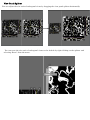
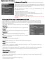
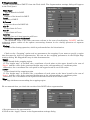
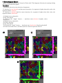
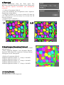
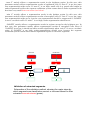
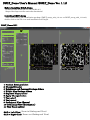
DSLT_Demo User’s Manual (DSLT_Demo Ver. 1.11)
Before Installing DSLT_Demo
Download and install the CUDA Toolkit 6.5.
(https://developer.nvidia.com/cuda-downloads)
Installing DSLT_Demo
After downloading the installation package (DSLT_setup_x64_111.exe or DSLT_setup_x86_111.exe),
double-click on the file icon and installation will begin.
DSLT_Demo GUI
①
⑦
⑪
②
③
⑨
XY
⑩
YZ
XY
④
⑧
⑤
ZX
⑥
1: Position Settings sliders
2: Channel Selector
3: Brightness and Contrast Settings sliders
4: Height Map Settings sliders
5: Segment Display slider
6: Apply Changes button
7: Tools shelf
8: Tools panel
9: Orthogonal View (Source)
10: Orthogonal View (Destination)
11: View Panel splitter
Shift + Left-Click: Zoom in (Orthogonal View)
Shift + Right-Click: Zoom out (Orthogonal View)
ZX
YZ
View Panel Splitter
You can adjust the size ratio of orthogonal views by dragging the view panel splitter horizontally.
You can reset the size ratio of orthogonal views to the default by right-clicking on the splitter and
selecting “Reset” from the menu.
Segmentation Procedure
1: Opening a 3D image file
In the File menu select “Open” or press Ctrl+O to open the image file.
This software supports 8, 16, and 32-bit TIFF image stacks and ImageJ
TIFF hyperstacks. We recommend using Fiji for conversion of a file in a
different format into one of these formats.
We use “ST_ami 1st adaxial 2-1.tif” for demonstration of the
segmentation procedure.
This file includes three channels:
Channel 0: fluorescence of nile red in silicone oil
Channel 1: fluorescence of nile red in phospholipid bilayers of cells
Channel 2: autofluorescence
We mainly used Channel 1 for segmentation.
Note that Channel 1 is used unless otherwise stated in the following
procedures.
2: Generating a height map to adjust brightness for depth
The height map is a 2D image to store surface elevation data of a 3D image. The software
allows adjustment of brightness for improved visualization with increasing depth from the
surface. This function enables correction for the reduction in signal intensity with penetration
depth of the excitation laser.
The Height Map panel enables adjustment of the following
parameters.
Filter Type:
Type of kernel for the smoothing filter that is applied to the
height map.
Radius:
Radius of a kernel for the smoothing filter that is applied to
the height map.
Smooth Lv:
Number of iterations of smoothing for the height map.
Z:
Radius of a kernel for the Z smoothing filter that is applied
before surface detection.
Threshold:
Threshold value for surface detection.
The following parameters can be adjusted after height map generation.
Offset:
Depth offset of the height map.
Range:
Depth range of maximum intensity projections along the z-axis. The projection results are
displayed on the orthogonal views (XY).
If the option “Use hmap for Z projection” is checked, a value for each point on the height map
will be used as a z coordinate for the starting point of the maximum intensity projection.
Generate Button:
Execute height map generation.
Clear Button:
Clear a generated height map.
If the option “Show height map” is checked, the height map is shown in the orthogonal views
(YZ, ZX) as purple curves.
1) Set parameters for generation of a height map.
2) Click “Generate” button.
3: Brightness and Contrast adjustment
If the option “Z Gradient” is checked, brightness adjustment for improved
visualization depth will be activated.
New intensity values 𝐼new are calculated with the following formula:
𝐼new 𝑥, 𝑦, 𝑧 = Coefficient ∗ 𝑧 Exp ∗ 𝐼 𝑥, 𝑦, 𝑧
1) Check “Z Gradient”.
2) Set parameters for brightness adjustment.
4: Smoothing
Select “Smoothing” from the tool shelf, and the Smoothing box will
appear in the Tools panel.
Filter Type:
Type of kernel for the smoothing filter.
Radius:
Radius of the kernel for the smoothing filter
1) Set parameters for smoothing.
2) Click “Preview” button.
To apply the brightness adjustment and the smoothing settings, click on the “Apply
Changes” button. Perform smoothing and brightness adjustment for improved depth to all
channels.
(Select channel -> Brightness adjustment for depth -> Smoothing -> Apply Changes)
Ch. 0
Ch. 2
5: Segmentation
Select “Segmentation (DSLT)” from the Tools shelf. The Segmentation settings dialog will appear
in the Tools panel.
Filter Type:
Type of kernel for DSLT.
Radius:
Radius of the kernel for DSLT.
Level:
Quality of DSLT.
Z Correct
Correction factor for DSLT (𝛼).
min C:
Lower limit of 𝐶𝑐𝑜𝑛𝑠𝑡 .
max C:
Upper limit of 𝐶𝑐𝑜𝑛𝑠𝑡 .
Interval:
∆𝐶𝑐𝑜𝑛𝑠𝑡 that each loop iteration will have.
ValidTH (for segment validation):
The threshold value of the inner structure volume is the sum of multiplying “ValidTH” and the
estimated proper radius of the sphere structuring element in the closing operation of segment
validation.
Closing:
Radius of the closing operation, which is performed after the binarization.
Check on the “Cropping” option and set parameters for cropping if you want to specify a region
that becomes the object of segmentation. You can set the cropping parameters in the Height Map
settings dialog. We skipped this step in this demonstration.
Upper:
Upper bound of the cropping region.
If “Use height map” is checked, the z coordinate of each point on the upper bound is the sum of
“Upper” and the value of the generated height map at the corresponding x-y coordinate point.
Otherwise, the z coordinate for each point on the upper bound is set to this value.
Lower:
Lower bound of the cropping region.
If “Use height map” is checked, the z coordinate of each point on the lower bound is the sum of
“Lower” and the value of the generated height map at the corresponding x-y coordinate point.
Otherwise, the z coordinate of each point on the lower bound is set to this value.
Edge:
X-Y edge thickness surrounding the cropping region.
We recommend that you check the results of the DSLT before segmentation.
1) Set parameters for segmentation.
2) Click on the “Apply” button in the Segmentation settings dialog.
6: Segment Editing
Correct segmentation errors.
Select “Segment Erosion” and “Segment Dilation” from the Tools shelf.
The respective settings dialogs will appear in the Tools panel.
Segment Erosion
Erode selected segments.
If “Clamp” is checked, a voxel at an edge of an image will not be eroded.
Radius:
Radius of erosion.
Segment Dilation
Dilate selected segments.
Radius:
Radius of dilation.
Middle-Click: Select a segment
Alt+J: Join selected segments
Alt+S: Separate selected segments
Ctrl+Z: Undo
Alt+A: Select all segments
Alt+D: Deselect all segments
1)
2)
<Over-segmentation>
1) Select over-segmented segments.
2) Join selected segments (Alt+J).
<Under-segmentation>
1) Select an under-segmented segment.
2) Erode the selected segment
(radius = 3, clamp = checked).
3) Perform segment separation (Alt+S).
4) Dilate the separated segments (radius = 3).
5) Join fragments.
The radii of the erosion and the dilation
should be the same.
3)
1)
2)
4)
5)
7: Extracting Air Spaces
Select “Segment Selection th” from the Tools shelf. The Segment Selection th settings dialog
will appear in the Tools panel.
Threshold:
Threshold value for auto-selection of segments.
If “deselect” is not checked and the mean intensity of a segment is higher than this value, the
segment will be selected.
If “deselect” is checked and the mean intensity of a segment is higher than this value, the
segment will be deselected.
1) Switch over to channel 0
2) Set “Threshold”
3) Click on the “Apply” button ---- (perform auto-selection (roughly select
airspaces))
4) Switch over to channel 2
5) Check “deselect”
6) Set “Threshold”
7) Click on the “Apply” button ---- (perform auto-deselection (deselect plastids))
8) Check selection errors, and then join the selected segments (Alt+J).
3)
7)
8)
8: Watershed
Select “Watershed” from the Tools shelf. The
Watershed settings dialog will appear in the Tools panel.
This function ignores unselected and undisplayed
segments.
1) Select all segments (Alt+A).
2) Set the minimum size of segments on the segmentdisplaying setting dialog
3) Deselect plastid if you want to obtain 3D data for
cells. This process is not necessary if you want only 3D
data for airspaces.
4) Switch over to channel 1
5) Click on the “Apply” button.
1)
2,3)
9: Morphological Smoothing (Optional)
Perform morphological smoothing to remove small
protuberances.
Select “Segment Dilation” and “Segment Erosion”
from the Tools shelf. The respective settings dialogs
will appear in the Tools panel.
1) Select all segments (Alt+A).
2) Erode segments (radius = 3, clamp = checked).
3) Dilate segments (radius = 3).
4) Erode segments (radius = 3, clamp = checked).
5) Dilate segments (radius = 3).
6) Erode segments (radius = 1, clamp = checked).
10: Saving Results
File (Menu bar) > Save
File (Menu bar) > Save_Segments
Parameter Settings
Source
max C = 4
max C = 10
max C = 20
Source
min C = 2
min C = 4
min C = 6
Source
ValidTH = 200
ValidTH = 800
ValidTH = 1600
“max C” mainly affects a segmentation result in the brightest region. In this case, this
parameter mainly affects segmentation results of epidermal cells. If “max C” is too low, some
over-segmentation might occur. If “max C” is too high, small cells (e.g. guard cells) might be
under-segmented because the segment validation system cannot detect under-segmented cells
that have very small inner structure (see below).
“min C” mainly affects a segmentation result in the darkest region. In this case, this
parameter mainly affects segmentation results of mesophyll cells. If “min C” is too low, some
over-segmentation might occur, but the over-segmentation should be suppressed if “ValidTH”
is set to a realistic value. If “min C” is too high, under-segmentation should occur.
“ValidTH” mainly affects a segmentation result in regions except for the brightest one. In
this case, this parameter mainly affects segmentation results of mesophyll cells. Even if
“ValidTH” is too low, it should not affect results significantly when “min C” is set to a realistic
value. If “ValidTH” is too high, under-segmentation should occur because the segment
validation system cannot detect under-segmented regions as incorrect segments.
Correct
Closing
AND
Incorrect
Closing
AND
Validation of extracted segments.
Schematics of the validation method, showing the major steps by
which segments are classified as correct or incorrect based on their
extracted inner structures (green).