1
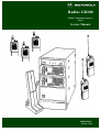
Radius GR300
ZR310 Community Repeater
Panel
Service Manual
6880902Z68-C
March, 1993
Table Of Contents
ZR310 Community Repeater Panel
Section 1
Introduction
Overview
Standard Configuration
....... System Functions
....... User Functions
Physical Description
Section 2
Installation
Overview
Equipment Required For Installation
Installation Procedures
Assembly
.......Install the ZR310 into the GM300
.......Fan Installation
...... Initial Turn-On
...... Diagnostic Commands
...... Programming
Section 3
Operation
Overview
Basic Operation
...... TPL Tones and DPL Codes
...... User Validation
...... Enabled Users
...... Co-Channel Protection
...... Regenerated TPL/DPL/CSQ
...... Carrier Repeat
...... Reserve Users
...... When a User Unkeys Radio
............ Morse Code Station Identification
............ Reserve Mode
............ Courtesy Tone
............ Barge in (Privacy Mode)
............ Repeater Hang Time
............ Encode During Transmit Hold Time
...... Stuck Mic Timeout Timer
...... Anti-Kerchunker Filter
...... Accessory PTT Encode
...... Repeater Set-up / Knockdown
March, 1993
6880902Z68-O
Table Of Contents
Table Of Contents
ZR310 Community Repeater Panel
Section 4
Theory of Operation
Overview
Circuit Description
...... Microprocessor
...... Serial Communications
….. TPL/DPL Decoding
...... DTMF Decoding
...... TPL Encoding
...... DPL Encoding
...... Beep Tone Encoding
...... Squelch/Repeat Audio
...... CSQ Input
Section 5
Maintenance
Overview
Preventive Maintenance
...... Visual Inspection
...... Cleaning
...... Diagnostic Commands
Disassembly
...... Removal
...... Top Cover Removal
Troubleshooting
Section 6
Programming
Overview
Programming Via Radio Service Software (RSS)
...... Getting Started
...... Programming the Repeater
...... Reading the Transmitter Radio
...... Reading the Receiver Radio
...... Configuring the System
............ System Programmable Fields
.................. Program Mode Access Code
.................. Morse ID interval, Speed and frequency
.................. Courtesy Tone Frequency
.................. System ID User Number
.................. Carrier Only Repeat (Open Repeater)
.................. Accessory PTT TPL/DPL encode
.................. Anti-Kerchunker Timer
.................. Timeout timer
March, 1993
6880902Z68-O
Table Of Contents
Table Of Contents
ZR310 Community Repeater Panel
............ User Programmable Fields
.................. Enable a User
.................. Reserve a User
.................. Receive (RX) Squelch Decode
.................. Station ID Call Sign
.................. Transmitter Hang Time
.................. TPL/DPL Encode During Transmitter Hang Time
.................. Privacy Mode (Barge-In)
.................. Courtesy Tone
.................. View All Users
.................. Radio Parameters
.................. Low Battery Alert
............ Customizing Your Accessories
Programming Over-The-Air
...... Entering the Program Mode
...... Exiting the Program Mode
...... Entering a Command
...... Program Mode Access Code
...... DTMF Command Descriptions
............ System Commands
.................. Repeater Set-up / Knockdown
.................. Stuck Mic Timeout Timer
.................. Mic DTMF Hang Time
.................. Carrier Repeat (CSQ) User
.................. Courtesy Tone
.................. System ID User
.................. System ID Frequency
.................. System ID Interval
.................. System ID Speed
.................. Anti-Kerchunker Timer
.................. Accessory PTT Encode
.................. Program Access Code
............ User Programmable Features
.................. Enable a User
.................. Disable a User
.................. Transmitter Hang Time
.................. Reserve a User
.................. Translate Tone/Set Encode Tone
.................. Transmit Squelch Codes
.................. TPL Encode During Transmit Hang Time
.................. Privacy Mode
.................. Courtesy Tone
.................. Morse ID Call Sign
.................. Verify a Users Station ID
.................. Co-Channel Protection
March, 1993
6880902Z68-O
Table Of Contents
Table Of Contents
ZR310 Community Repeater Panel
............ Diagnostic Commands
.................. PTT On/Off (Key the Transmitter)
.................. Open/Close Audio Path
.................. Audio Test Tone
.................. Encode a TPL Tone or DPL Code
.................. TPL Tone Sweep Start/Stop
.................. List the Number of Enabled Users
.................. List the Enabled User Numbers
.................. List Resets. Power Fails, Program Access
.................. System test, List Any Error Numbers
.................. Reset to Default Settings
...... Quick Reference to DTMF Codes
Programming via Telephone
Programming via ZR310 Monitor Program
...... Real-Time Display
Record Programmable Values
Appendix A - DTMF Commands
Table A-1 DTMF System Commands
Table A-2 DTMF User Commands
Table A-3 DTMF Diagnostic Commands
March, 1993
6880902Z68-O
Table Of Contents
Section 1
Introduction
Overview
The ZR310 is a community repeater panel (Figure 1-1) which provides individualized repeater service for up to 70 customers or customer
groups on a single RF channel. It acts an interface between a GM300 transmit radio, and a GM300 receive radio, providing TPL and DPL
encode/decode, repeat audio processing, and all timer functions. An internal database holds the various attributes associated with each user
group. Nearly all of the ZR310's functions can be customized for each of the 50 TPL tones and 20 DPL codes.
You can program all of the functions of the ZR310 in three ways:
•
•
•
Remotely, using DTMF over the radio channel
Locally, with the Motorola RIB compatible interface for connection to a computer
By using a touch-tone telephone
Standard Features
The following is a list of ZR310 Community Repeater Panel features.
•
•
•
•
•
•
•
•
•
•
•
Decoding / Encoding for 50 TPL tones and 20 DPL codes.
Remote control and programming via DTMF radio, or DTMF from a telephone plugged into the programming jack.
Remote enable / disable of all user groups.
Per-user programming.
Cross-tone, cross-code, tone-code encoding.
Privacy made prevents "barge-ins".
Vacant tones and codes can be reserved.
Courtesy tone.
Automatic station ID per user.
Accessory PTT input with selectable TPL / DPL encode.
Repeater set-up / knockdown remote DTMF commands.
System Configuration
Unlike a conventional community repeater panel. which usually consists of a system card (or equivalent circuitry) and up to 70 different
plug-in tone cards, the ZR310 incorporates one card that allows system and user programming.
System Functions
System programming replaces the system card in a conventional community repeater panel. The system function controlled by the ZR310
software are listed below:
•
•
•
•
•
•
•
•
•
•
System Access Code
Repeater Set-up / Knockdown
Time-out Timer
Courtesy Tones Frequency
Anti-Kerchunker Filter
Station ID
Speed, Timer, Frequency
Program Mode Access Code
Accessory PTT TPL / DPL Encode
Carrier Repeat ID
March, 1993
6880902Z68-O
Section 1-1
Section 1
Introduction
User Functions
In the ZR310, assigned user numbers are the equivalent to the 70 plug-in tone cards contained in a conventional community repeater panel.
The following steps describe the process the ZR310 uses to find user information.
1.
2.
3.
The ZR310 detects a code or tone.
The code / tone is decoded to a user number.
The user number points to the area in the database containing information about that particular user. Re to Table 3-1 for code / tone
to number conversion.
The user functions controlled by the ZR310 software are listed below:
•
•
•
•
•
•
•
•
User Enable
TPL or DPL Encode
Reserve Mode
TX Hang Time
Morse ID Call Sign
Courtesy Tone
Co-Channel Protect Selection
Privacy Mode
Physical Description
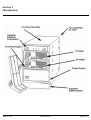
The ZR310 is a self-contained repeater interface component designed to fit into the top shelf of the GR300 Repeater Station.
The front panel (Figure 1-1) contains
•
•
•
•
•
Audio adjustment
TPL / Set-up adjustment
LED indicators. to display the status of the various functions
Programming jack, used for DTMF telephone programming or local programming with an IBM PC via an RIB programming
interface
Interconnections to the transmit and receive radios are made via the 16-pin Transmit and Receive connectors located in the rear of
the panel.
March, 1993
6880902Z68-O
Section 1-2
Section 1
Introduction
March, 1993
6880902Z68-O
Section 1-3
Section 2
Installation
Overview
This section explains how to install the ZR310 community Repeater Panel into the GR300 and complete the cable connections that were
started in the Installation section of the GE300 Maintenance Manual. If you require access to the indicators, jumpers, or other components,
refer to the Maintenance section for disassembly procedures.
Equipment Required For Installation
The following equipment is required for installation:
•
•
•
•
•
a communications service monitor and ONE of the following
a hand-held or mobile radio with DTMF encode capability
a DTMF telephone
a PC capable of running the Motorola radio service software (RSS)
an ANSI terminal communications program
Installation Procedures
If you have followed the installation procedures found in the Installation section of the GR300 main manual, the GR300 is assembled. Now
you need only to install the ZR310, finish the required cable connections, reinstall the fan assembly, and perform the required tests and
adjustments. To identify the parts and their corresponding call outs, refer to Figure.
Assembly
Perform the following steps to install the ZR310 into the GR300 housing and to complete cable connections. The RF and repeater cables
should already be connected to the radios, if you installed them according to the Installation section of the GR300 Maintenance Manual.
Install the ZR310 Into the GM300
1.
STOP! Before going any further, did you make sure that the jumpers inside the GM300 transmit and receive radios were set to the
correct positions? (Refer to table 2-2.)
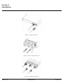
2. Place the ZR310 on the top shelf of the GR300 repeater housing, allowing the rear panel to be partially exposed.
3. Connect the receive radio repeater connector to the ZR310 Receive connector (Figure 2-1).
4. Connect the transmit radio repeater cable to the ZR310 Transmit connector.
5. Position the ZR310 so that its mounting screw holes are aligned with the corresponding mounting holes on the repeater housing
6. Using a T25 Trox screwdriver, secure the ZR310 to the repeater housing using two M5x0.8x8 machine screws (7).
7. One end of the equipment power cable has only one connector. Connect it to the top connector on the power supply (Figure 2-2).
8. The other end of the equipment power cable has two connectors. Connect one of these connectors to the receive radio and the other
to the transmit radio.
9. Connect the lower frequency radio to the LOW port on the rear of the duplexer. (Figure 2-3).
10. Connect the higher frequency radio to the HIGH port on the rear of the duplexer. (Figure 2-3).
11. Thread the grounding nut onto the grounding lug.
CAUTION
To avoid damage to cable tabs and radio components,
install cables with locking tabs up
March, 1993
6880902Z68-O
Section 2-1
Section 2
Installation
Figure 2-1. ZR310, Rear View
Figure 2-2. Power Supply, Rear View
Figure 2-3. Duplexer, Rear View
March, 1993
6880902Z68-O
Section 2-2
Section 2
Installation
Fan Installation
Perform the following steps to reinstall the fan assembly in the repeater housing. Due to a limited amount of space in the
back of the repeater housing, you must connect the power cable before installing the fan. To free both hands for easier
installation of the power cable, you may want to rest the fan assembly on top of the repeater housing.
1. Connect the fan assembly power cable between the bottom connector of the power supply and the fan assembly
connector that extends out the rear (refer to Interconnect Cabling Diagram)
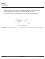
2. Side the yellow lead of the fan assembly power cable containing the thermistor into the thermistor clip (Figure 2-4).
Figure 2-4. Thermistor Clip
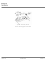
3. Using a Torx screwdriver, secure the thermistor clip to the mounting hole located on the transmit radio heat sink with a M5x0.8x8 taptite
screw (Figure 2-5).
March, 1993
6880902Z68-O
Section 2-3
Section 2
Installation
Figure 2-5. Transmit Radio, Rear View
Locate the cable tie wrap supplied with the GR300.
March, 1993
6880902Z68-O
Section 2-4
Section 2
Installation
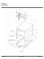
Figure 2-6.
Section 2-5
6880902Z68-O
March, 1993
Section 2
Installation
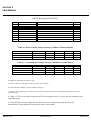
GR300 Housing Kit HLN8391_
Item
1
2
3
4
5
6
7
8
Part Number
None
1580675B01
0310943M59
0310907A91
0780676B01
6480495C01
0310907B08
03136993
Description
Fan Assembly
Cover
Screw, Taptite, M3.5x0.6x6
Screw, Machine, M3.5x0.6x8
Base Tray
Front Plate
Screw, Machine, M5x0.8x8
Screw, Machine, 6-32x3/8"
Qty.
1
1
4
4
1
1
8
4
Table 2-1. Receive Radio Jumper Settings (GM300 16 Channel Models)
GM300 Jumper
JU551
JU651
JU701
R*I*C*K
B
X
X
ZR310
A
X
X
ZR320
B
X
X
ZR330
B
X
X
i50R
B
X
X
Table 2-1. Transmit Radio Jumper Settings (GM300 16 Channel Models)
GM300 Jumper
JU551
JU651
JU701
R*I*C*K
X
A
A
ZR310
X
A
B
ZR320
X
A
A
ZR330
X
A
A
i50R
X
A
X
4. Bundle the cables with the cable tie wrap.
5. Dress the cables so they don't extend out the back of the GR300.
6. Position the fan assembly (1) in the repeater housing (2).
7. Align the set of mounting screw holes on the rear of the fan assembly with the corresponding mounting holes on the
repeater housing.
8. Using a T15 Torx screwdriver and four M3.5x0.6x6 taptite screw (3), secure the fan assembly to the
repeater housing.
9. Verify that all screws are tight and all cables have been connected properly. Refer to the
Interconnect Cabling Diagram located in the back of the manual.
March, 1993
6880902Z68-O
Section 2-6
Section 2
Installation
NOTE
You will not install the front plate of the repeater
housing until you have completed all tests and
adjustments under the heading Tests and Adjustments.
Initial Turn-On
The following steps describe the process of turning on the ZR310 for the first time.
1. Remove protective covers from both radios LED displays
2. Connect the power cable into a 115/230Vac power source
NOTE
The "115/230" switch on the bottom of the power
supply must be in the position corresponding to the
power source. You should have done this during the
GR300 basic assembly.
3. Turn on the power supply. The unit is on when the red portion of the switch is visible.
4. Turn on both radios by rotating the volume controls clockwise.
5. Verify that the ZR310 green Power LED is illuminated, the display windows on both radios are illuminated and the fan
is operating.
Diagnostic Commands - Refer to Programming Section, Diagnostic Commands.
Programming - To customize the ZR310 to your particular application, refer to the Programming section.
March, 1993
6880902Z68-O
Section 2-7
Section 3
Operation
Overview
Theis section describes the basic operation of the ZR310 Community Repeater Panel. Included is a list of all TPL and DPL tone codes with
their decoded user numbers. Refer to the programming section of this manual to customize your community repeater.
Basic Operation
Installing the ZR310 in the GR300 Repeater Station converts the GR300 Repeater Station into a multi -user community repeater. The ZR310,
via a microprocessor, performs data management to simultaneously decode and encode TPL and DPL tones.
TPL Tones and DPL Codes
The ZR310 monitors the channel for TPL Tones and/or DPL codes. When it detects a tone or code, it implements conversion to a user
number (Table 6-2). Next, it points to the area in the database that contains information about that particular user. The DPL decode numbers
in the table are user programmable.
User Validation
The ZR310 is always monitoring the receive audio for the presence for a valid user. You can enable or disable any of the 50 TPL tones, and
any combination of the 20 DPL codes. For information on how to enable or disable a user, refer to the programming section of this manual.
Enabled Users
When the ZR310 detects an enabled TPL tone or DPL code, it will check to see if the user is enabled or disabled. A disabled user is ignored
and is not repeated.
Co-Channel Protection
For each user, you can select co-channel protection on/off. If the ZR310 detects an enabled TPL/DPL user when co-channel protection is
transmitting, it will check to see if a carrier is present on the repeater transmit channel. If the transmit channel is busy (possibly due to paging
or other activity not present on the repeater receive channel), the ZR310 will "protect the channel" and wait for it to clear before keying the
transmit radio. The co-channel protection feature determines whether or not the ZR310 has priority on the channel.
March, 1993
6880902Z68-O
Section 3-1
Section 3
Operation
Regenerated TPL/DPL/CSQ
When you key the transmit radio, depending on the programming, the ZR310 will
•
•
Encode nothing for carrier squelch
Regenerate the received TPL ton or DPL code
Encode a different TPL tone or DPL code (cross-tone encoding)
Carrier Repeat
The ZR310 can also be configured as a "carrier repeater", or sometimes called an "open repeater". In this mode, any activity on the receive
radio causes the transmit radio to key.
The ZR310 can also provide tone control (TPL/DPL) and open repeater operation simultaneously. In other words, users that have no encode
(CSQ) repeat just like users that have TPL or DPL encode. This allows a mix of TPL/DPL users with one repeat capability and is ideal when
upgrading TPL/DPL users to an existing open repeater channel.
To enable carrier repeat, a user number is identifies as the "carrier" repeater user. This allows all standard user programmable features for
open repeat, including enable/disable for the carrier user, TPL or DPL encode encoding, courtesy tone, etc. If the user number is set to "0",
no carrier repeater is available.
Reserved Users
If a user is "reserved", the repeat audio will be squelched an a beep tone sent on the transmit audio when the user tries to use it. A chirp tone
is sent when the user unkeys to indicate reserve mode.
When a User Unkeys Radio
When a user radio unkeys, or the TPL/DPL is no longer detected, the ZR310 will take some actions. The following paragraphs describe
possibilities of that action.
Morse Code Station Identification
When an enabled user unkeys, the ZR310 checks how long it has been since the last time the station ID has been sent. If the time has been
longer than the Morse ID interval time (initially 15 minutes, user programmable 1-99 minutes), then the ZR310 sends the call sign. Each user
group has its own call sign and individual ID interval timer. The Morse ID is sent at the selected ID speed of between 4 and 25 words per
minute. The call is sent at 30% deviation (FCC part 90 rules) so that voice communication still occurs during the voice ID.
NOTE
If the Morse ID is not programmed, or the first
character is programmed as a "space", no ID is sent.
You can program a single system ID for use in co-op
and private carrier applications.
March, 1993
6880902Z68-O
Section 3-2
Section 3
Operation
Reserve Mode
If the user is in the reserve mode when unkeying, a "chirp" is sent. This chirp gives a positive indication of active reserve mode.
Courtesy Tone
The ZR310 will next check to see if the user requires the courtesy beep. If so, then it sends the beep one second after the transmit radio
unkeys. The beep frequency can be sent from 400 to 2500 Hz (default setting is 1000 Hz). If the user is a 400 Hz tone just after the GR300
unkeys, potential failure has been detected.
Barge In (Privacy Mode)
Finally, the ZR310 continues checking for TPL/DPL. If the last user is set for "privacy mode", then no other users will be allowed on the
system until the transmit hold time (repeater "tail") expires.
Repeater Hang Time
The programmable repeater "tail" or transmit hold timer is adjustable from 0.0 to 25.0 seconds. When the user radio unkeys, the ZR310
begins monitoring for valid TPL/DPL tones to be received. If a valid user is not detected within a specified timeout period, the IPL decode
shuts off or the DPL turn off code is sent (if it was previously on). After a 0.2 second delay, the transmit radio PTT is dropped. This method
removes the second squelch tail heard by the mobiles when the user radio unkeys.
Encode During Transmit Hold Time
When a valid user unkeys, the TPL or DPL encode may be left on or turned off during the transmit hold time. This feature is programmable
for each user. When using a control station phone patch through the repeater, you should turn off the encode during transmit hold. Turning
off the encode allows the phone patch to distinguish whether the mobile has unkeyed or the repeater has dropped off the channel. When
using the repeater for dispatch only, you may leave the encode on during the transmit hold time to keep the mobile decoders open. This
feature eliminates the decode delay observed in the mobile between transmissions.
Stuck Mic Timeout Timer
While the Gm300 mobile radios are conversing through the repeater, a timeout is running. If a mobile does not unkey within the time period,
double beeps are sent, and the transmit radio PTT is dropped.
Anti-Kerchunker Filter
The anti-kerchunker filter cancels the transmit hold time (or repeater tail) and drops the transmit radio immediately if a mobile transmission
is less than the programmed anti-kerchunker time. This discourages customers from clicking (kerchunking) the PTT just to hear the transmit
radio.
Accessory PTT Encode
An Accessory device such as a tone remote or local microphone may key the transmit radio, and take over control of the repeater. The
accessory may need the ZR310 to encode a particular TPL tone or DPL code in order to communicate with a specific user group. The ZR310
includes a programmable "Accessory PTT" encode setting to accomplish this function. Whenever an accessory keys the transmit radio, the
ZR310 disables the repeater transmit hold time until 30 seconds of "no accessory transmit" has expired.
March, 1993
6880902Z68-O
Section 3-3
Section 3
Operation
Repeater Set-up/Knockdown
The system operator may remotely enable or disable the ZR310 operation. When in "knockdown" state, the ZR310
effectively disables the transmit radio. (Refer to Programming section, DTMF Command Descriptions, System
Commands, Repeater Set-up/Knockdown.)
March, 1993
6880902Z68-O
Section 3-4
Section 4
Theory of Operation
Overview
This section provides the experienced technician with a thorough understanding of the ZR310 circuits and their operation. This information
will aid the technician in troubleshooting the equipment.
Circuit Description
Use this detailed circuit description in conjunction with the schematic diagrams in the back of the manual.
Microprocessor
To ensure an orderly power up sequence to microprocessor U1. and its peripheral devices, the active low reset signal is not brought up until
the 12 vdc supply has stabilized. Zener diodes CR5, R22/C28, and U4D accomplish this task. The delayed reset also gives crystal Y1 time to
stabilize. An additional reset input comes from the long DTMF reset circuit. This circuit is a fail safe device to allow the system operator to
reset the unit remotely by keying a DTMF digit for longer than 12 seconds.
Memory is functionally divided into three sections: (1) program memory, (2) operating memory, (3) protected database memory. Program
memory resides in ERROR U8 and stores the actual operating instructions that make the ZR310 work as a community repeater panel.
Operating memory is provided by static read/write memory RAM U3 and the internal memory in microprocessor U1. The ZR310 performs
computations and maintains a data buffer in this area. Database memory contains all the user and system programming values and must be
retained regardless of how often power is lost. To do this, the ZR310 stores the user and system programming values in EEPROM U5.
Peripheral timers and counters, U14 and U15 are available to the microprocessor. The counter IC's contain thee timers each which are used
for tone generation and internal timing functions.
The microprocessor is able to directly control 8 I/O lines that interface to its Port 1 register on pins 13 through 20. These carry information
from the various digital control outputs and inputs.
Serial Communications
Asynchronous data transfer is accomplished via a microprocessor U1's internal UART. The UART receives data through pin 11 of the
microprocessor but first it is buffered to be compatible with the Motorola RIB interface via Q10/Q11/U16A. Data is transferred through pin
12 of U4 then is buffered with the same RIB interface circuit. The RIB interface baud rate is connected by the baud clock output on pin 6 of
timer U15. This baud clock output is applied to the microprocessor U1 bit clock input on pin 10.
TPL/DPL Decoding
Unquenched discriminator receive audio passes through unity gain stage U18B then gets low pass filtered by U18C and U18A. This removes
the voice component from the audio. The U18D and the R66/C63 filters make up a zero crossing detector, which applies the resulting digital
signal to the microprocessor on pin 17. The microprocessor performs the actual decoding for the TPL tones and DPL codes using proprietary
digital signal processing techniques.
DTMF Decoding
The mobile audio from the receive radio discriminator passes through unity gain stage U18B, then low pass filtered by U16C. Finally the
signal is presented to the DTMF encoder/decoder U10. U12A is used to switch the audio to the DTMF decoder between receiver audio, and a
DTMF telephone plugged into the programming socket J1. When a telephone (or any low impedance) is plugged into J1, U16B will sense
the voltage drop across RP7D and switch the audio to the DTMF decoder.
March, 1993
6880902Z68-O
Section 4-1
Section 4
Theory of Operation
TPL Encoding
Two signals are used for TPL generation:
•
•
Clock frequency at the exact TPL rate from the microprocessor
Clock frequency at 64 times the TPL rate from the timer module
These signals are fed into a switched capacitor low pass filer U17, then sent to the transmitter.
DPL Encoding
For generating DPL signals, the microprocessor sends the digital code out its pin 9. Data inversion is done inside the microprocessor if
required. The timer module produces a high frequency clock signal that is fed into the low pass filter U17. Operation is very similar to TPL
encoding described above.
Beep Tone Encoding
Timer U15 generates progress tones (Morse ID, warning beeps, etc). Square wave output is filtered and summed at the transmit audio
junction U11D, then it passes through the output buffer amp to the transmitter audio input at P2-2.
Squelch/Repeater Audio
The repeat audio is passed through input unity gain stage U18B, the audio hi-pass filter U11 and U11A to remove the TPL/Digital encode,
de-emphasized by the R29/R30/C34 network and finally to squelch gate.
U12B and U12C. The microprocessor controls the squelch gate. The repeat audio is summed at the transmit audio junction U11D, then
passes through the output buffer amp to the transmitter audio input at P2-2
CSQ Input
From the 8 or 16 channel GM300 radio, U4B and U4F are used to select the CSQ input connection and polarity. The COR logic signal is
presented to the microprocessor input port pin 20.
March, 1993
6880902Z68-O
Section 4-1
Section 5
Maintenance
Overview
This section contains information and procedures that will enable the technician to proform preventive maintenance and troubleshooting
techniques on the ZR310 Community Repeater Panel. Fault isolation and component-level troubleshooting are not covered in the section.
Preventive Maintenance
Preventive maintenance of the ZR310 consists of:
•
•
•
Visual inspection
Periodic cleaning
Checks using diagnostic commands entered via the DTMF keyboard
Visual Inspection
Check that external surface of the equipment are clean, that connecting cables are not damaged, and that connections are firm. A detailed
inspection of the interior electronic circuitry is not needed or desired.
Cleaning
Periodically clean smugges and grime from the exterior housing. Use a soft, non-abrasive cloth moistened in a mild soap and water solution.
Rinse the surface using a second cloth moistened in clean water.
Diagnostic Commands
Refer to Programming section, Diagnostic Commands.
Disassembly
In order to inspect the cable and other components, and to remove the top cover, you must remove the ZR310 from the GR300 housing.
Complete the steps in paragraphs 3.1 and 3.2 to accomplish this.
Removal
To remove the ZR310 from the repeater housing, perform the following steps:
1. Place the GR300 power switch to off and unplug the ac line from the ac supply outlet.
2. Using a T15 Torx screwdriver, remove the four M3.5x0.6x6 taptite screws (3) that secure the fan assembly to the
repeater housing.
3. Remove the fan assembly (1) and rest it on top of the repeater housing.
March, 1993
6880902Z68-O
Section 5-1
Section 5
Maintenance
NOTE
In order to have enough room to move the fan
assembly around and to remove the ZR310, you will
have to cut the cable tie wrap. Make sure that you
obtain another cable tie wrap for use when
reassembling the GR300.
4. Using a T25 torx screwdriver, remove the two M5x0.8x8 machine screws that secure the ZR310 to the repeater housing.
5. Remove the ZR310 from the repeater housing.
6. Disconnect the transmit and receive radio repeater cables from the transmit and receiver connectors.
Top Cover Removal
To remove the top cover from the ZR310 for inspection of components and to make necessary adjustments, perform the following steps.
1. Using a #1 Phillips screwdriver, remove the four #4-40x3/16" flathead machine screws.
2. Remove top cover.
Troubleshooting
There are two forms of troubleshooting:
•
Finding problems with the ZR310 "system: operations. The troubleshooting charts provided in Table 2-2 will aid in resolving these
system issues.
•
Repair of a defective ZR310. An experienced technician with the commonly available test equipment, the schematic diagram
located in the back of this manual and the PC overlays should have no difficulty finding the problem area and faulty component(s).
The ZR310 schematic diagrams provide the circuit detail for isolating malfunctioning components. [The troubleshooting charts provides....]
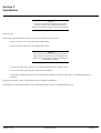
Before proceeding with troubleshooting, scan Table 5-1 to determine if you can solve the existing malfunction. By reading this information,
you could save valuable time by isolating the circuit where the faulty component os located.
Problem/Indication
400Hz beep just before
transmit radio unkeys
Memory automatically reset
to default positions
Unit fails
ZR310 does not detect TPL
tones
March, 1993
Possible Solution
Memory problem
At reset/power: > 15 errors detected
Reset unit: send DTMF digit from
mobile/handheld radio to repeater site for
> 15 seconds
Carrier LED is off
6880902Z68-O
Section 5-2
Section 6
Programming
Overview
This section contains information and procedures that allow the technician to program the ZR310.
You can program the ZR310 in the following ways:
•
Motorola RIB compatible interface, using a computer running Motorola radio service software (RSS) designed for the ZR310
•
DTMF over the radio channel ("over-the-air") from a mobile, base station, or handheld
•
DTMF from a telephone plugged into the programming jack on the front of the ZR310
•
ZR310 monitor program via RS232 Communications Program'
Programming Via Radio Service Software (RSS)
We recommend that you program the ZR310 using a PC that runs the Motorola Radio Service Software (RSS), because it is the easiest
programming method. Using this software allows you to access the programmable features of the ZR310 from user-friendly screens on the
PC. You can archive the final configuration for safekeeping or later examination.
The programming port on the ZR310 is hardware compatible with the Motorola RIB. The RSS will prompt the system installer to plug into
the ZR310 so that the configuration can be read or written to the ZR310.
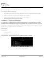
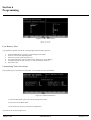
Getting Started
At the Main Menu:
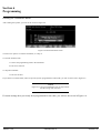
1. Press F3 (Get/Save)
You will see the Get/Save Screen, Radio Mode (Figure 6-1).
We recommend that the radio be programmed in repeater mode. To begin programming in repeater mode:
Figure 6-1. Get/Save Screen, Radio Mode
March, 1993
6880902Z68-O
Section 6-1
Section 6
Programming
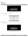
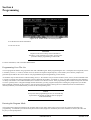
2. Press F6 to change to repeater mode.
You will see the Get/Save Screen, Repeater Mode (Figure 6-2)
Figure 6-2. Get/Save, Repeater Mode
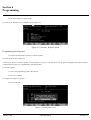
Programming the Repeater
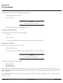
1. From the Get/Save Menu, Press F2 to read the repeater.
You will see the screen in Figure 6-3.
You have two options: to read the repeater, or to designate it as a generic. You may need to use the generic designation if the option board is
not physically accessible (i.e. programming a replacement radio).
To read the repeater:
1. Connect the programming cable to the repeater.
2. Frees F2 to continue.
To designate the repeater as generic:
1. Press F10 to abort
Figure 6-3. Read Repeater Screen
March, 1993
6880902Z68-O
Section 6-2
Section 6
Programming
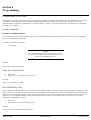
Reading the Transmitter Radio
After reading the repeater, you will see the screen in Figure 6-4.
Figure 6-4. Read Transmitter Screen
You have two options: to read the transmitter, or to skip it.
To read the transmit radio:
1. Connect the programming cable to the transmitter.
2. Press F2 to continue.
To skip the transmitter:
1. Press F10 to abort.
If you choose to read the radio, and it has previously been programmed in radio mode, you will see the screen in Figure 6-5.
NOTE
Figure 6-5 is for your information only. It may indicate
that the wrong radio was read.
If custom settings have previously been programmed for the radio, you will see the screen in Figure 6-6.
March, 1993
6880902Z68-O
Section 6-4
Section 6
Programming
Figure 6-6. Non-Default Information Warning
To allow all programming information to reset to default settings:
1. Press F2 to continue.
CAUTION
To keep custom programming, you must use radio
mode. If custom settings have previously been
programmed for the radio, you will see the screen in
Figure 6-6. Programming in repeater mode resets all
custom accessory information to its default settings.
Pressing F2 (Continue) will overwrite any custom
programming.
Reading the Receiver
After reading the ZR310 option board and the transmitter, you will see the screen in Figure 6-7.
Figure 6-7. Read Receiver Screen
March, 1993
6880902Z68-O
Section 6-5
Section 6
Programming
You have two choices: to read the receiver, or to skip it
To read the receiver:
1. Connect the programming cable to the receiver.
2. Press F2 to continue.
To skip the receiver:
1. Press F10 to abort.
As with the transmitter, if the radio has previously been programmed in radio mode, the warning screens in Figure 6-5 and Figure 6-6 may
appear.
Configuring the System
From the Main Menu:
1. Press F4 (Change/View).
2. Press F2 (Radio/Wide).
You will see the screen in Figure 6-8.
Figure 6-8. ZR310 Configuration Screen
Table 6-1 lists the functions you can perform from within the ZR310 Configuration Screen.
March, 1993
6880902Z68-O
Section 6-6
Section 6
Programming
Table 6-1. Command Key Function
Command
F1=HELP
F2=GOTO USER
F3=PREVIOUS
USER
F4=NEXT USER
Function
Get specific help for highlighted field
Choose a user number to display (TPL=1-50;
DPL=51-70)
Go to previous active user (both enabled and
reserved users are active)
Go to next active user (both enabled and reserved
users are active)
F5=PRINT
Print contents of screen.
SCREEN
F6=VIEW ALL
View user summary screens
F7=DELETE USER Delete currently displayed user from active list.
F8=ADD USER
Add new user to active list
F10=EXIT
Go to previous menu (Change/View)
Table 6-2 lists other keys and their general function.
Table 6-2. Other Key Functions
Key
ESC
Tab/Enter/Return
Shift + Tab
Up / Down Arrow
Left/Right Arrow
Back space
Page Up/Page
Down
March, 1993
Function
Exit Main Menu
Accept data currently in field and move prompt
forward one field
Accept data currently in field and move prompt
backward one field
Scroll through selections or increase/decrease
current relative value.
Move cursor left/right one space
Erase current character in field and move cursor
left one space
Display previous/next page of information on
screen
6880902Z68-O
Section 6-7
Section 6
Programming
From the ZR310 Configuration Screen, you may set the programmable features. Programmable feature in the ZR310 are divided into three
categories:
•
•
•
System Programmable Fields
User Programmable Fields
Diagnostic Tests
System Programmable Fields
The following subparagraphs describe the system commands available for the ZR310.
Program Mode Access Code
The program mode access code is a number between 1000 and 32000.
Morse ID interval, Speed, and Frequency
You can program the Morse Code station identification in frequency, interval and speed. The following table outlines the programmable
range and the default settings of each.
Table 6-3. Station ID Programming
Frequency
Interval
Speed
Programmable Range
400-2000Hz
1-99
4-25 wpm
Default
1200Hz
15 Min
22 wpm
Each user on the ZR310 has its own independent station ID timer that is accurate to one second per interval. When the station ID is sent, the
timer is reset. The call is transmitted on the first dispatch message after the timer has expired.
During normal dispatch, the minimum character speed will be 15 wpm. This allows the "List" functions (using Morse code as a format) to be
sent at very slow speed, while maximizing airtime use during normal dispatch.
Courtesy Tone Frequency
The courtesy tone is used for courtesy tone and prompt beeps. It is programmable in frequency from 400 to 2500 Hz, and the default setting
is 1000 Hz.
A possible reason to change the frequency could be to differentiate between co-channel repeaters to know which repeater site is active.
System ID User Number
A user number may be assigned as the "System ID user number" so that the repeater will identify every ID interval (1 to 99 minutes).
Before sending the System ID, the following conditions must be met:
•
•
•
The system ID interval timer must expire (adjustable 1 to 99 minutes).
The ZR310 must be inactive (TPL/DPL Decode LED off).
The System ID must have a number programmed.
March, 1993
6880902Z68-O
Section 6-8
Section 6
Programming
The ZR310 will reference the system ID user for the proper TPL/DPL encode and the Morse ID to send. You can use a disabled or enabled
user number.
The Morse code station ID is sent after a 0.75 second key up delay.
Carrier Only Repeat (Open Repeater)
You can program the ZR310 to repeat based on just the carrier, sometimes called "carrier controlled repeat", or "open repeater". In this mode,
the ZR310 provides simultaneous tone/open repeater operation for users that have TPL or DPL encode or that have no encode repeat. Both
types of users operate normally. This allows a mix of TPL tone users with open repeat capability and is ideal when adding tone users to an
existing open repeater.
To enable the carrier (CSQ) for repeat, you can identify a user number as the "carrier repeat user". This allows all standard userprogrammable features for open repeat, including enable/disable, TPL or DPL code encoding, etc for the carrier user, if the CSQ user number
is set to "0", no carrier repeat will be available.
Accessory PTT TPL/DPL encode
An accessory device such as a tone remote or local microphone may key the transmit radio, and take over control of the repeater. The
accessory may need the ZR310 to encode a particular TPL tone or DPL code in order to communicate with a specific user group. The ZR310
incudes a programmable " Accessory PTT encode" settings to accomplish this function. When an accessory keys the transmit radio, the
ZR310 will disable the repeater transmit hold time until 30 seconds of no accessory transmit has expired.
Anti-Kerchunker Timer
The anti-kerchunker timer may be programmed between 0 (off) and 5.0 seconds.
The first transmission from a user must be longer than the anti-kerchunker timer value or the programmed transmit hold time will not be
used. This discourages users from "kerchunking" the repeater.
Timeout Timer
The timeout timer is a "stuck mic" timeout feature. Its setting determines the maximum amount of time a mobile may transmit on the
channel. Each time the TPL/DPL decode stops, the timer is reset. It may be set from 1 to 9 minutes, in one minute increments, and the default
setting is 3 minutes. During a timeout condition, you will hear an alert tone before the transmit radio unkeys.
March, 1993
6880902Z68-O
Section 6-9
Section 6
Programming
User Programmable Fields
Enable a User
To activate a user in the ZR310, you must enable the TPL tone or DPL code user number. The transmit radio keys when the carrier and the
TPL tone or DPL code are decoded.
Set the Status line as Enable to activate a user.
Reserve a User
You may need to reserve a TPL tone or DPL code for future use. If a user keys up on a "reserved" user number, the transmitter will be keyed
but it does not cut through a repeat audio. It sends a beep tone for the duration of the transmission. This mode is to disable a user for seasonal
use or a possible "no-pay" condition. A reserved user will keep the tone active in the repeater, preventing other co-channel repeater operators
from seeing the tone as "available".
NOTE
Before reserving a user, you must enable that user
Receive (Rx) Squelch Decode
The ZR310 can decode all 50 TPL tones and up to 20 DPL codes. The TPL user numbers are 1-50, and they have fixed frequencies. The
DPL user numbers are 51-70. Each of these user “slots” in the database can decode any valid DPL code, so you must set the digital "code
number". When you set the DPL decode number, the ZR310 will automatically set the encode to the same DPL code. (Refer to Table 6-3 for
TPL tones / DPL codes.)
Station ID Call Sign
A station ID call sign is a Morse code ID assigned to a particular user. This ID may be eight characters long, and may be any combination of
numbers or letters.
You can program an individual Morse code ID for each user number. The first time the user unkeys, the ZR310 sends the Morse code ID. If
the user keys up again, voice communications may occur during the ID. The ID is sent at 30% deviation and a selectable speed from 4 to 25
(default is 22) words per minute (meets FCC Part 90 regulations). With System Programming, you can set the ID tone frequency from 400 to
2000 Hz so that it does not interface with paging or other tone signalling on the channel. You can set the ID interval from 1-99 minutes. You
may also program a single System ID call sign. Refer to Table 6-4 for the Station ID Cross Reference and Table 6-5 for the TPL tone / DPL
code conversions.
Transmitter Hang Time
The transmitter hang time is the amount of time the repeater transmitter remains keyed on the channel after mobile activity is no longer
detected. The transmitter hang time must be set to a value between 0.0 and 25.0.
TPL/DPL Encode During Transmitter Hang Time
Normally the repeater encode signal follows the mobile encode. However, You can leave a TPL or DPL encode on during the transmitter
hang time. By leaving the encode on, you can eliminate the decode time between transmissions, thus not losing any audio.
Choose Y to leave the encode on during transmit hang time, or no to turn it off.
March, 1993
6880902Z68-O
Section 6-10
Section 6
Programming
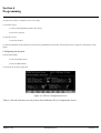
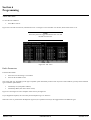
View All Users
To view the user numbers"
1.
Press F6 to view all
Figure 6-9 is the TPL User Screen, which shows users 1-50. Figure 6-10 is the DPL User Screen, which shows users 51-70.
NOTE
The F6 key will now toggle between the TPL User and
the DPL User Screens.
Figure 6-9. TPL Users
Radio Parameters
From the Main Menu
1.
2.
Press F4 to see the Change / View Menu.
Press F5 for the Mode screen.
This screen will vary, depending on the type of repeater option board that you have read. If you have read a ZR310, you may choose between
types of ZR310 option boards:
•
•
Community PA (with public address)
Community RMT (with tone remote--C100)
Figure 6-11 and Figure 6-12 are examples of the screens you might see.
If you skipped the repeater, the screen may list the Repeater Type as "Generic".
When the cursor is positioned on the Repeater Type line, the up/down arrow keys will toggle between the different types.
March, 1993
6880902Z68-O
Section 6-12
Section 6
Programming
Figure 6-100. DPL Users
Figure 6-11. Can't do
Figure 6-12. Can't do
Low Battery Alert
To program the repeater to send out a warning signal when its battery gets low:
1.
2.
3.
4.
5.
From the Main Menu, press F4 to see the Change/View Menu.
Press F7 to access the Signalling Menu.
Press F2 to see the screen in Figure 6-13.
Using the arrow keys, move the cursor to the space next to "Low Battery".
Using the up/down arrows, choose Y to set the low battery alarm on.
6. Press F10 to exit.
Customizing Your Accessories
The repeater may be customized in radio mode. To set custom accessory information:
Figure 6-13. Radio Wide Screen
1. From the Main Menu, press F4 to see the Change/View menu.
2. Press F2 to access Radio Wide.
3. Press F9 for the Accessory Connector Configuration.
You will see the screen in Figure 6-14.
March, 1993
6880902Z68-O
Section 6-13
Section 6
Programming
Figure 6-14. Radio Wide Accessory Screen
4. Set the desired custom information.
5. Press F10 to exit.
CAUTION
Repeater mode will not keep custom information.
Therefore, if you customize your radios, you may limit
yourself to always programming in radio mode.
For more information, refer to the Basic RSS Manual.
Programming Over-The-Air
You can program the ZR310 using a portable radio with a DTMF keypad. While programming the unit. it is helpful, but not required, to have
a secondary receiver (i.e. scanner, monitor receiver) tuned to the repeater output frequency. This enables you to hear the prompt tones
generated by the ZR310. The access code is user-programmable (System Programming, in this section).
All numbers may be entered with or without leading zeros (i.e. the number 1 may be entered as 0001#, 001#, 01# 1#). Some commands send
a progress or prompt tone while programming, and all commands send either a "go-ahead" or "error" tone after completion of the command.
A "chirp" tone follows a successful command, and a "warble" tone denotes an error. If the programming radio switches slowly from transmit
to receive (possibly due to a keypad interdigit transmit hold time), you may program a delay before sending the prompt tones (see the Mic
Hold command). Although you do not have to wait for each prompt tone before entering the next command (because all commands are
internally buffered), we recommend that you listen for the corresponding tones.
NOTE
At any time while programming the unit, if no DTMF key
is pressed for 90 seconds, the ZR310 will exit program
mode automatically.
Entering the Program Mode
The transmit radio remains keyed during the program mode to keep other radios from trying to access the system and interface with
programming. A command is provided to unkey the transmit radio (diagnostic commands), and if this command is selected, the radio will
key only to send prompt tomes.
March, 1993
6880902Z68-O
Section 6-14
Section 6
Programming
The following steps describe how to enter the programming mode:
1. Enter a program mode access code.
2. Press the "#" key.
NOTE
The default access code is 12310#
3. Listen for three chirps, which indicate proper access.
Exiting the Program Mode
The following steps describe how to exit the program mode:
1. Enter 99.
2. Press the "#" key.
3. Listen for the ringing prompt tone, which confirms that you have exited program mode.
Entering a Command
The following steps describe how to enter a command:
1. Enter a DTMF number.
2. Press the "#" key. Some commands require additional numbers (i.e. cross tone encoding).
NOTE
If you make an error while entering a number the "*" key
function as a "clear entry" key.
Commands are grouped in three main categories:
•
•
•
System Commands
User Commands
Diagnostic Commands
Each command is described under "DTMF Command Descriptions" on page 6-8. A quick reference commands summary is shown in the
tables in Appendix A. If you are familial with DTMF commands, you may skip this section and program the ZR310 using the information
given in Appendix A.
For commands identified with "uu" you may enter the user number to program a single user. To program all users (1-70) at once, enter "99"
as the user number.
March, 1993
6880902Z68-O
Section 6-15
Section 6
Programming
Program Mode Access Code
The following paragraphs describe the system, user and diagnostic commands available for the ZR310 when programming "over-the-air" or
via telephone. These include the options available with RSS programming. For detailed information about each option, refer to the
paragraphs under "Programming Via Radio Service Software (RSS)" on page 6-1. Enter each command as described in the "Programming
Over-The-Air" on page 6-7.
System Commands
Repeater Set-up/Knockdown
The system operator may remotely enable (set-up) or disable (knockdown) the ZR310 operation. When in "Knockdown" state, the ZR310
effectively disables the transmit radio.
To disable (knockdown) the repeater:
1. Enter 300#
NOTE
This command will take the repeater out of service until
you reaccess the program mode, cycle the main power, or
perform a "long DTMF digit reset".
Example:
300# - Take repeater out of service.
Stuck Mic Timeout Timer
1.
2.
Enter 201#.
Enter time t# in one-minute increments (1-9).
Example:
201# 5# - Set timeout to 5 minutes.
Mic DTMF Hang Time
The mic DTMF hang time feature allows you to insert a delay before the ZR310 sends back prompt tones during DTMF programming. This
option is useful for over-the-air programming. In many radios equipped with DTMF encode, the transmit radio does not unkey immediately
after it releases a DTMF digit. As long as the radio is still keyed, the prompt tones do not sound on the programmer's radio. To remedy this
condition, you can program the ZR310 to delay sending the prompt tones. You can set the delay from 0 to 3 seconds, in one-second
increments, and the default setting is 0.
1.
2.
Enter 281#.
Enter time t# in one-second increments (0-3).
Example:
281# 2# - Set 2-second delay before prompt tones.
March, 1993
6880902Z68-O
Section 6-16
Section 6
Programming
Carrier Repeat (CSQ) User
1.
2.
Enter 203#.
Enter the CSQ user number uu# (0-70).
Example:
203# 49# - CSQ users repeat as user 49
Courtesy Tone
1.
2.
Enter 209#.
Enter the beep frequency ffff# in Hz (400-2500).
Example:
209# 1200# - Set courtesy tone to 1200 Hz
System ID User
1.
2.
Enter 208#.
Enter the user number uu# (0-70, where 0 = off).
Example:
208# 49# Sets user 49 as the system user.
Station ID Frequency
1.
2.
Enter 206#.
Enter the frequency ffff# in Hz.
Example:
206# 1000# - Set station ID frequency to 1000 Hz.
Station ID Interval
1.
2.
Enter 205#.
Enter time tt# in minutes (1-99).
Example:
205# 15# - Set station ID interval to 15 minutes.
March, 1993
6880902Z68-O
Section 6-17
Section 6
Programming
Station ID Speed
1.
2.
Enter 207#.
Enter speed ss# in words per minutes (4-25, Default = 22).
Example:
207# 15# - Set station IS speed to 15 minutes.
March, 1993
6880902Z68-O
Section 6-18
Appendix A
DTMF Commands
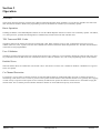
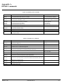
Table A-1. DTMF System Commands
Command
201# t#
202# tt#
203# uu#
204# nn#
205# tt#
206# ffff#
207# ss#
208# uu#
209# ffff#
210# n#
213# nn#
214# aaaaa#
281# t#
300#
99#
Function
Set stuck mic timeout timer to t minutes
Set anti-kerchunker filter timer to t.t seconds
Set CSQ user number uu
Accessory PTT TPL/DPL, 0=off
Set station ID interval to tt
Set station ID tone frequency to ffff Hz
Set station ID speed to ss WPM
Set system ID user number to uu
Set courtesy beep tone frequency ffff
DPL acquire maximum bit errors
TPL turnoff code detect delay
Set program mode access code aaaaa
Set Mic DTMF hang time to t seconds
Repeater Knockdown
Exit Program Mode
Parmeter
t=1-9 minutes
tt=0.1-5.0 seconds (0=disable)
uu=0-70
nn=50 for TPL, 1000-1777 for DPL
tt=1-99 minutes
ffff=400-2500 Hz
ss=4-25 WPM
uu=0-70 (0=off)
ffff=400-2500 Hz
aaaaa=0-32000
t=1-3 seconds
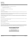
Table A-2. DTMF User Commands
Command
110# uu#
111# uu#
112# uu# ee#
115# uu#
116# uu#
120# uu#
121# uu#
122# uu#
123# uu# ttt#
130# uu#
131# uu#
140# uu#
141# uu#
151# uu#
150# uu#
160# uu#
161# uu#
March, 1993
Function
Disable user number uu
Enable user number uu
Set user uu's DPL decode to code number ee
Enable user uu's co-channel busy protect
Disable user uu's co-channel busy protect
Disable user uu's TPL/DPL encode during transmit hold time
Enable user uu's TPL/DPL encode during transmit hold time
To translation, user uu encodes tone/code ee
Parameter
uu=1-70
uu=1-70
uu=51-70
ee=0 for CSQ, 1-50 for TPL, or
1000=uu for DPL
ttt=0.0-25.0 seconds
Set tramsit hang time tt.t for user uu
Disable user uu reserve mode disabled, normal repeat audio operation
Enable user uu reserve mode, doesn't pass repeat audio
Disable user uu privacy mode, normal operation
Enable user uu privacy mode, no new users allowed until transmit radio drops
out
Enable user uu courtesy tone
Disable user uu courtesy tone
Set users uu's Morse ID to xx, xx, ...
xx, xx, ... up to 8 characters
Play back user uu's ID
6880902Z68-O
A-1
Appendix A
DTMF Commands
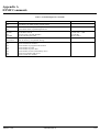
Table A-2. DTMF Diagnostic Commands
Commands
301#
302#
303#
304#
305# tt#
305# tttt#
306#
307# ffff#
308# ffff#
309# 25327#
360#
361#
362#
363#
364#
365#
366#
367#
March, 1993
Function
PTT on
PTT off (keys up when sending progress tones)
Repeat audio disable, squelch/unsquelch test
Repeat audio enable, squelch/unsquelch test
Encode TPL tone tt
Encode DPL code tttt
TPL tone sqeep, end with DTMF #
Encode TPL frequency fff.f
Encode frequency ffff
Clear all memory, setup default settings
List the number of enabled users
List the enabled user numbers
List the number of program mode accesses
List the number of resets
List the number of power fails
List the number of users with memory errors
List the User numbers with errors
List the system error number
6880902Z68-O
Parameter
tt=1-50 or 0=none
tttt=octal code + 1000
50 to 300 Hz
ffff=50.0-300.0
400-3000 Hz or 0=none
A-2