1
Engine: Fuel Injection
Engine: Fuel Injection
FAQ Home
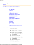
Volvo Maintenance FAQ for 7xx/9xx/90 Cars
Identification and Maintenance:
Bosch vs. Rex/Regina
Setting Base Idle Specs and TPS on Bosch LH2.4-Equipped
Cars
Setting Base Idle and Mixture Specs on Bosch LH2.2Equipped Cars
Relieving Fuel Pressure When Opening FI System
Fuel Injectors:
Injector Cleaning
Injector Seals
Injector Diagnosis
Cold Start Injector
Homemade Fuel Injector Cleaner
Troubleshooting:
Vacuum Leak Diagnosis
Vacuum Hose Replacement
Fuel Pump and FI Relay Diagnostic Tests
Idle Air Control Valve
PTC Nipple in 90+ Turbos
Fuel Pressure Regulator
Testing or Repairing Bad Fuel Injection Relay
Radio Suppression Relay
Oxygen Sensor Diagnosis
Air Mass Meter Diagnosis
ECU Failure
file:///C|/Users/Steve/Documents/Volvo%20FAQ%20Updated/EngineFuelinjection.html[01/13/14 10:04:34 PM]
Engine: Fuel Injection
Carbon Vapor Canister
Air Box Thermostat Change
Exhaust Smell: Leaking Injector Seals?
Engine Storage/Used Engine Notes
Abbreviations:
AMM Air Mass Meter
ECT
Engine Coolant Temperature sensor
ECU
Engine Control Unit computer (either fuel injection
or ignition)
FI
Fuel Injection
FPR
Fuel Pressure Regulator
IAC
Idle Air Control solenoid valve
TB
Throttle Body
TPS
Throttle Position Sensor
VSS
Vehicle Speed Sensor
Identification and Maintenance:
Bosch vs. Rex/Regina.
Which Injection System Do I Have?
[Response: Chris Mullet/Chris Herbst] Many 1990+ non-turbos have Rex/Regina
systems; most turbos seem to have Bosch. Between 90 to 92, all non-California
non-turbos were Regina cars. There were some 89s and there were some 940s
until 1993 if not later. The Regina cars are anything but rare. Regina systems are
characterized by:
Variable Fuel Pump Setups: Many Regina cars have only one main fuel pump
which is in the tank and no under-car pump; this fuel pump is reputed to be
not as high a quality as Bosch. However, some 1989 to 1992 cars have Regina
FI and two fuel pumps (both in-tank and under-car) similar to a Bosch
system. The fact that your car has only one fuel pump is NOT proof that it has
a Regina system, as the exception above notes. In addition, later 940s have
Bosch LH 2.4 FI systems but single in-tank Bosch fuel pumps) .
Ignition coil is a wierd sort of amplifier-looking thing on the LH strut tower,
versus a standard looking cylinder-shaped coil.
Uses an intake air temperature sensor and a manifold air pressure (MAP)
sensor, instead of the mass airflow meter.
Relays are often but not always similar to Bosch; see Electrical: Circuits and
Relays for locations and applications.
Idle air control valves are not interchangeable
file:///C|/Users/Steve/Documents/Volvo%20FAQ%20Updated/EngineFuelinjection.html[01/13/14 10:04:34 PM]
Engine: Fuel Injection
Oxygen sensors are not interchangeable, regardless of what many aftermarket
suppliers claim. Buy only the Regina-specific unit which is usually more
expensive.
Regina Technical Data. A scanned copy of the Volvo Regina green book is here.
Setting Base Idle Specs and TPS on Bosch LH2.4-Equipped Cars . [Adapted
from Volvo Service Manual 32043/1]
Cleaning the Throttle Body: See the discussion in Engine:Performance for more
information
Adjusting the LH2.4:
1. Adjusting Idle Linkage Rod.
Ensure that when the cable drum is pushed off its endstop with a 2.5 mm feeler
blade, the gap between throttle lever and adjustment screw is from 0.1 and 0.45
mm. (This is the adjustment screw that mounts on the throttle lever, not the
adjustment of the larger nut that attaches the lever to the throttle plate shaft). To
achieve the above spec, adjust the throttle link rod (ball-socketed connection rod
between drum and throttle lever)
2. Checking the Throttle Body (Plate and Throttle Position Switch) Adjustment
Connect an accurate tachometer then warm up the engine. Let it idle in Park with
a/c off. Pinch off the hose between the air intake and the IAC valve (don't damage
the hose with something sharp!) Idle speed should drop below 500 rpm, or the
engine may stop: both are normal. If idle speed does not drop, adjust as below.
3. Adjusting the Idle Speed
On the front side of your throttle body, there is an adjustment screw. Loosen the
lock nut. Start the engine and turn the adjustment screw until idle is 480-520 rpm.
Switch off the engine and tighten the lock nut while holding the adjustment screw
so it doesn't turn.
4. Checking the TPS Adjustment.
Check the gap between the adjustment screw and the throttle lever with a feeler
gauge. Insert a .45mm feeler gauge. There should be no click from the Throttle
Position Switch on the rear side of the throttle body when the throttle is closed.
Then insert a .15mm feeler gauge. There should be a click from the TPS when the
throttle is closed. If these are incorrect, then adjust as below.
5. Adjusting the TPS.
Loosen the TPS adjustment screws holding it to the throttle body. First turn the
TPS clockwise (away from the electrical connector) until it stops. While keeping
your finger on the throttle disk so it won't move, turn the TPS counter-clockwise
(toward the connector) until you hear or feel a click. Continue turning until it stops,
then tighten the screws. Go back to step 3 above to check the adjustment.
file:///C|/Users/Steve/Documents/Volvo%20FAQ%20Updated/EngineFuelinjection.html[01/13/14 10:04:34 PM]
Engine: Fuel Injection
Setting Base Idle Specs and Mixture on Bosch LH2.2-Equipped Cars.
A. LH 2.1, 2.2 Jetronic Cars. [Courtesy of MVP, Volvo performance parts
suppliers]
Many driveability and running problems can be traced to improper base engine
settings. Setting your base idle specifications is always the first step when trouble
shooting any runability problem. By following the steps below the source of most
problems can be identified
1. Check for air leaks by spraying carburetor cleaner on all intake hoses and
gaskets. Any fluctuation in idle while an area is being sprayed means a leak.
Repair any leaks you find. Don't spray carburetor cleaner on hot manifolds as
it may cause a fire.
2. Remove and clean the throttle body, adjust the throttle plate open 1/4 turn.
Reinstall it using new gaskets. Make sure the throttle switch clicks as soon as
you crack the throttle (adjust as needed).
3. Start your engine and let it warm up fully.
4. Set ignition timing to the manufacturer's specs.
5. Now use a voltmeter (with minimum impedance 10 megohm for a digital unit)
to verify that your 02 sensor is working properly. Connect the red positive
probe from the voltmeter to the 02 sensor wire where it is connected to the
large green wire by peeling back the connector cover and backprobing the
contact leaving the sensor still connected. Connect the black negative probe
from the voltmeter to ground. A good 02 sensor will fluctuate between .2 and
.7 volts if your mixture is anywhere close. Replace the 02 sensor if needed.
6. Go to the right inner fender well (740's) or the left inner fender well (240's)
and find the red and white pigtail that sits besides the ignition ECU. This is
your idle speed test point. [Note: wiring colors can vary: some 760s use
red/black.Check the OEM wiring diagram manual; aftermarket versions may
not have the correct colors.] Ground this connector and adjust the bypass air
thumbscrew on the throttle body until the idle is 725 RPM's. Remove the
ground from your test point; the idle should be close to 750 RPM's.
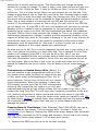
7. Next to the idle speed test point pigtail is a green and white pigtail. This is
your carbon monoxide or mixture test point, which measures the oxygen
sensor output. Using Volvo special tool part #9995280 (approx. $35) plug one
end of the test LED to the fender well connector and the red connector to the
positive terminal of the battery. A logic probe can be used in place of the
Volvo special tool or if you are handy build the circuit below. Remove the
tamper proof plug from the air mass meter by drilling two 1/8" holes in the
plug about 3/16" deep and removing the plug with needle nose pliers or snap
ring pliers. This will reveal the mixture adjusting screw. Adjust the AMM until
the LED on the tester blinks on and off at equal intervals. Congratulations! You
have just set your engine's base idle specs. Note: when the tester LED is off it
represents a lean mixture, when it is on the mixture is rich.
file:///C|/Users/Steve/Documents/Volvo%20FAQ%20Updated/EngineFuelinjection.html[01/13/14 10:04:34 PM]
Engine: Fuel Injection
LH 2.1 & 2.2 Notes. [Art Benstein/John Sargent] The LED adjustment procedure
presumes everything affecting mixture is in the ball park to begin with. Stuff like
vacuum leaks, fuel pressure, injectors will throw the mixture off more than that pot
(screw adjustment) will correct. If the O2 sensor isn't working, e.g. clogged with
soot from rich running, the LED test point will not switch. It is actually monitoring
the output of the first circuit inside the ECU that handles the O2 sensor signal, so
the flashing indicates the switching between lean and rich that occurs while the ECU
is maintaining the correct mixture. Because AMMs are slightly different in response,
an adjustment is given on the AMM to adjust the ECU to match it up until LH2.4
when the ECU became automatically adaptable to the slight variations in sensor
output. A better procedure to use in replacing AMMs would have you measuring the
voltage on the yellow lead (LH2.2) before you adjust or disconnect the old one.
Then you could at least put the pot back where it was if needed or set the new one
to the same value before installing it. You could measure the resistance, but it is
much easier to backprobe the voltage as you set the pot-- it varies from zero to
about 2.7V-- then you don't need to guess where you ran out of adjustment. The
ends are very hard to feel. Turning the AMM adjustment screw CounterClockWise
gives a lean mixture, so turning the screw ClockWise gives a rich mixture. The
mixture setting method using the LED tool gives a slightly lean mixture compared
to the more accurate exhaust gas analyzer probe. Turn the AMM adjustment screw
2-3 turns CW (rich) to put the mixture adjustment in the right range.
Instead of using the test port, you can put a multimeter (with minimum impedance
of 10 megohm for digital units) on the O2 sensor output. You should get an
oscilliting voltage from about 0.1 to 0.9 volts. If your O2 sensor is generating a
fairly even duty cycle between .1 and .9V, the system is in closed loop and the
mixture is correct. The test point, if you are on it (pin 22 on the -544 ECU) is an
open collector output protected by a 511 ohm series resistor-- pretty hard to
damage externally. You don't really need the 750 ohm resistor, and its value
certainly isn't critical to the function; just protects the LED if you drop the ECU end
of the probe on a ground. The LED just shows you what the ECU sees as crossings
of stoich point (which you will see graphically if youI use a 'scope on the oxygen
sensor lead and set the crossing for 450 mv) with a set of comparators a bit on
either side of that midpoint. That having been said, it can take more than a few
turns on the AMM pot screw to adjust it, and some just won't adjust no matter
what.
B. LH 2.4 Jetronic Cars. Idle is monitored and controlled by the ECU, acting
through the Idle Air Control valve, and is not separately adjustable.
Relieving Fuel Pressure When Opening FI System. [Tip from Charles Probst,
Bosch Fuel Injection & Engine Management, Bentley] The fuel system is under
pressure even when the engine isn't running. To prevent fuel from spraying over
yourself and the engine when opening a fuel line, there are three good ways to
file:///C|/Users/Steve/Documents/Volvo%20FAQ%20Updated/EngineFuelinjection.html[01/13/14 10:04:34 PM]
Engine: Fuel Injection
relieve pressure in the lines:
Neat: pull the fuel pump fuse (number 1), then crank/run the engine until it
dies.
Quick: wrap the fuel fitting in a shop cloth and loosen it, but it can be tricky
and messy manipulating two wrenches, the fuel line, and the cloth.
Fancy: connect a hand vacuum pump at the pressure regulator; when you
pump vacuum, the regulator will dump pressure to the fuel tank.
Always remember to remove the fuel tank cap to relieve pressure in the tank.
Pressure in the tank can be enough to squirt fuel from the lines after they're open.
Fuel Injectors:
Injector Cleaning. [Editor's Tip: see Michael Ponte's excellent illustrated
discussion of injector cleaning at http://www.mikeponte.com/volvo/injectors.htm]
Problems With Deposits. Because the fuel filter stops dirt before it reaches the
injectors, the main cause of injector clogging is not dirt but fuel varnish. When tiny
drops of fuel vaporize around the injector nozzle, they leave behind trace
compounds that can buildup over time and restrict the nozzle opening. Gasoline is
supposed to contain detergents to wash away these deposits and keep the injectors
clean. But recent reports indicate that many cut-rate brands of gasoline don't
contain adequate levels of detergent for this. Dirty injectors restrict fuel delivery
and cause a lean fuel condition. The result can be rough idle, hesitation and
stumbling when accelerating - and even lean misfire.
Injector Deposit Removal. [Inquiry: What is the best injector cleaner?] I've tried
a few kinds but I found that removal and flushing of the injectors and replacement
of the injector seals really is the best. I removed the injectors in my 85 245 Turbo
(K-jet) and took them to a shop and they pressure tested and flushed them. Even
with all the injector cleaner I ran through (some of it was pretty expensive), they
were still really crudded up. After the flush they were like new. The flush and test
cost $13.00, the seals (for my brick there was a thin one on the injector holder,
and a fat doughnut one on the injector itself - not sure what your brick has) were
$3.00 (?). Total cost is much less than bottles of injector cleaner that are (in my
case) of limited help. I guess in really bad cases a new injector may be required,
but not with my brick. Injector removal and installing was pretty straightforward and I'm not all that handy with tools.
[Tip from Shane] As for sending them out and getting cleaned, look in the back of
Turbo Magazine for RC Engineering. They're an injector specialty place, and can do
everything but downsize an injector (clean, blueprint, balance, flowmatch, enlarge,
anything!).
[Lyle Domico] I was able to use a Mityvac to backflush my injectors with straight FI
cleaner. Pull the injectors and strip off o-ring seals. Pour a little cleaner in a spray
can cap. Set up your Mityvac with the brake bleed bottle attached. Wrestle the
Mityvac hose onto the top fitting of the injector. Set injector upright in the cap of
cleaner and pump up the vacuum. Gently press down on the injector to open the
needle valve on the bottom and the cleaner will start to flush up through the
file:///C|/Users/Steve/Documents/Volvo%20FAQ%20Updated/EngineFuelinjection.html[01/13/14 10:04:34 PM]
Engine: Fuel Injection
injector, effectively backflushing it, including the screen.
[Response 2:] I used expensive injector cleaner with marginal success - so I did an
injector overhaul. There are some shops that do a complete flush without removing
the injectors using some technique, but I decided to do it myself. Removing
injectors was straightforward - just keep things clean. I took the injectors to a
shop and they did a pressure flush ($15). There are other home ways to do this
like using bicycle pump with pure injector cleaner - but after a few attempts I
decided not to try. They were badly crudded but after a bit of flushing, were good
as new. After 220 K km, the shop said they were just fine. I also replaced the 2
rubber o-rings. One around the injector (fat doughnut type) and one around the
injector holder (skinny ring type). The o-ring around the injector holder was brittle
- so the new rings sealed a big vacuum leak. Use silicon lubricant to ease the oring replacement. All this took a couple of hours. Made a big difference at idle.
[Editor] Numerous shops will clean and test injectors. One Internet shop is
witchhunter.com charging around $15 each with quick turnaround.
[Tip from Ed O'Briant] My experience with a rough idle still present after a tune up
and TB, IAC cleaning, etc., on higher mileage cars has been this (assuming no
vacuum leaks, etc.): dirty, clogged, sticky, leaky, and otherwise compromised fuel
injector operation. If you haven't done it, pull the fuel rail and the injectors. Either
bench clean them yourself or send them off to the proper folks. Chemicals in the
fuel tank don't cut it! They may help somewhat but in no way replace pulling those
bad boys! On our '90 745T with 115K miles, I found that all four of the injectors
had LOUSY spray patterns-streaming fuel instead of atomizing it. Also, two of the
injectors were leaking-when power alone was applied to the leakers, without
compressed air, the injectors just dripped cleaner when they should, of course, be
tight. Leaking injectors cause a very lumpy idle! Hard, brittle, cracked injector orings are also antithetical to smooth engine operation.
After cleaning, none of the injectors leaked and they atomized the cleaner so well
that the vapor hung in the air for a minute or more. Idle is now incredibly smooth.
Smoother and faster acceleration/deceleration, no hesitation, as well. A testament
to this is my wife's attempting to start the car TWICE since the injector cleaning,
which is not normally a problem, except the car was already running!
Remember this if nothing else: There is NO such a thing as a clean, optimally
performing fuel injector on a high(er) mileage engine, despite whatever the injector
manufacturers/oil refinery folks may say about modern injectors and fuel blends,
making injectors all but impervious to getting crudded up. It just ain't true.
Combustion Chamber Deposit Removal. See the FAQ section in Engine:
Mechanical for a water-based technique that works as well as the section in Engine:
Performance for gerneral notes on fuel intake deposit cleaning.
Injector Seals. [Tips from Tim Curry] These seals are very simple to install. As it
happens, the injector and pressure regulator o-rings (which are the same size) are
the same as those used on the injectors on a '92 Ford F-150 V-8. Those are quite
inexpensive and you get 16 seals in the kit.
Relieving Fuel Pressure.
file:///C|/Users/Steve/Documents/Volvo%20FAQ%20Updated/EngineFuelinjection.html[01/13/14 10:04:34 PM]
Engine: Fuel Injection
[Editor] To relieve fuel pressure at the rail, remove the fuel pressure regulator
vacuum line, attach a vacuum pump, and apply vacuum. This dumps excess
pressure into the tank.
[Tip from Brian] I wouldn't bother disconnecting the pump unless you want an
arm/face and a garage floor full of gas. There is fair amount of fuel in the lines,
and you would have to plug the line, or you'd just syphon all the gas out of your
tank. Disconnect the high pressure line at the injector rail (with a cloth handy).
Disconnect the return line as well, and tilt the rail to drain it. Otherwise, when you
fight with the injector and it comes flying off in a hurry when you finally win, you
might end up flinging fuel all over the place. Cover the open lines until you are
ready to reconnect them. And keep that trouble light - hopefully with a compact
flourescent - far away. They don't call it trouble for nuthin'.
Removing the Fuel Rail.
First disconnect the battery which will shut off the fuel system completely and
reduce chances of an impromptu BBQ under the hood. The fuel rail is the metal
tube that holds the injectors in place and provides fuel pressure. Using a backup
wrench, remove the high pressure fuel line on the top of the rail. Using pliers to
loosen the Corbin spring clamps, pull the vacuum line off the fuel pressure
regulator and the low pressure fuel return line. Be careful when you remove the
fuel rail hold down bolts: There are thin washers beneath them that are easily
dropped. Pull the rail with the attached fuel pressure regulator. [Tip from Gene
Stevens] CLEAN the junk out of the injector holes before you pull them: blow the
dirt out of the area around the base so it won't fall in. A straw will do if you don't
have compressed air. LUBE the hole with some WD-40 or a few drops of ATF. The
O-rings can bond themselves to the opening but if you wiggle them around a bit,
the lube can coat the surfaces that get exposed, then it'll slide right out. The are a
press fit into the rail and manifold but can become stuck with age, grunge and
dried rubber.
Removing the Injectors.
It is easiest to just pull the entire rail/injector assembly out of the manifold. If the
o-rings are really hardened in the manifold, the rail will first have to be separated
from the injectors before you try removing them. The metal u-shaped clips which
attach the injector body to the fuel rail just act as snap rings. They are pushed on
from the side and lock the fuel rail to the injector. Remove them from the rail on
your bench with the injector nozzles facing up so as not to damage the tips.
Replacing the Seals.
Use the seals in the kit (Bosch injector kit, import parts house, o-rings) with a
small dab of grease, vaseline or lubriplate and install them where the old ones
were. Do both top and bottom seals, greasing each one before it is installed. Note
that the kit may have extra parts that don't fit your injector. There is a plastic cap
that protects the injector's tip which can be replaced as well. The old cap will be
stuck so you may need to gently break it loose with a pair of vise grips, adjusted
to just barely crush the cap slightly. If you need to reuse the plastic caps on the
ends, warm them up with very hot water before removing, or they will break. Make
sure to use a dab of vaseline on the end of the injector before putting the plastic
cap back on, or it may split. I used a block of soft wood (pine scrap) with a hole
drilled in it so the injector needle wouldn't be damaged when pushing the tip back
file:///C|/Users/Steve/Documents/Volvo%20FAQ%20Updated/EngineFuelinjection.html[01/13/14 10:04:34 PM]
Engine: Fuel Injection
on. Don't bugger the end and needle, or you will be buying a new injector ($$$).
Now is a great time to replace the o-ring on the fuel pressure regulator too.
Installing the Injectors into the Rail.
Put the injector back in its recess in the rail (or in the manifold, if you are doing it
that way) using a small dab of lube and go to the next one. Do all of them or you
will cause leaks. When reattaching the u-clips, note that they insert in both the
bottom slot in the injector and engage the round washer-like protrusion on the fuel
rail. They should not be bent outwards: if they are, you've got them in the wrong
slot on the injector.
Installing the Fuel Rail.
[Tip from Gene Stevens] Again, it is probably easiest to mount the injectors in the
rail and then insert them into the manifold all at once. If you've lubed the o-rings,
they should slide right into the manifold holes. WD-40 or ATF works great. Grease
stays around and just holds the dirt, so liquid lube is better for servicing.
Put the rail back in place, tighten bolts, attach fuel lines and FPR vacuum line.
Make sure no parts are left over. Check everything again for tightness. Attach
battery. Start car. Check for leaks.
Be careful, take your time. Its not hard to do, just think and keep parts in a
container as you go.
Injector Specs. [Tip from Shane] There's only two different EFI injectors used on
Red Motor Volvos: 270cc/min (LHJet 2.2), and 300cc/min (LHJet 2.4). Wiring,
connection to rail, seals and caps, and everything else are the same, just a
difference in delivery.
Injector Diagnosis.
On the Car Diagnosis. Your Volvo's engine uses port fuel injection firing all
injectors simultaneously with some cross-over occurring within the plenum. The
injection pulses can vary considerably, and Volvo FI set-ups fire the injector twice
per revolution (keeps the valve wet between intake cycles) to prevent hardened
deposits from forming on the valves. This often results in enough fuel being present
for near-normal engine operation on three injectors. All four injectors fire at the
same time on +12V current supplied from the radio suppression relay (later cars)
or the car's power supply. The injectors fire when the FI ECU grounds the circuit.
Basic diagnostic tests for injectors include:
Using a volt meter to measure the voltage being supplied to the injectors:
place the + terminal in the + supply wire to each injector and the - terminal
on an engine ground. This will verify that the injector is receiving power.
Listening for injector opening/closing by placing a screwdriver against the base
of each injector when the engine is running. Placing an ear close to the handle
of the screwdriver should allow a faint clicking to be heard. This is the injector
solenoid opening and closing.
Using a noid light to verify that the injector pulse is occurring. A noid light is a
small, resistive lamp matched to the injector that is inserted into the injector
file:///C|/Users/Steve/Documents/Volvo%20FAQ%20Updated/EngineFuelinjection.html[01/13/14 10:04:34 PM]
Engine: Fuel Injection
harness and flashes each time the ECU grounds the injector. It won't tell you
much beyond the presence/non-presence of a pulse, but if one injector
harness has a weak flash, that tells you there is a circuit problem. If there are
no flashes and you've verified that each injector has +12V supplied to it, then
the ECU is not grounding the injectors and you have an ECU or wiring
problem. Buy a noid light specifically matched to Bosch PFI ("ported fuel
injection") systems from any one of a number of online vendors such as IPD
or a local NAPA store. Cost=$10.
Pulling the plugs for observation of combustion conditions within each cylinder.
Dark grey/brown indicates normal burn. Light grey/white indicates lean burn.
Black and oily usually means a rich burn or oil control problem.
Using a digital graphing meter or digital storage oscilloscope to see the
waveforms. These meters are not cheap, although a used two channel DSO
may be found on EBay for US$100 or so. For a good discussion about using a
digital scope (Fluke 97a or the like) to diagnose injector and fuel pump
problems, see Dave Goldberg's article on "Scope Use for Volvo "in the form of
a pdf file.
Checking the Injector Grounds on the Intake Manifold. [Don Willson] Injector
ground wires on the intake manifold are frequently corroded. Just cleaning
them and tightening the bolt is not enough. The wire must be soldered to the
crimp lug. The internal resistance of this crimp increases until injectors start
to missfire, the O2 sensor sees too much oxygen and feeds the engine much
too much fuel. Mileage drops to 10 mpg with smoke and no power.
Off the Car Diagnosis. You can remove the injectors and supply a similar voltage
to test them. To verify operation of the injectors, measure the spray pattern and
throughput of each using a graduated plastic beaker. Should one or more injectors
be inoperative, and if your engine has considerable mileage, replace all injectors &
fuel filters (including the small catch screen in the main fuel pump). Those on a
budget may try to clear the injectors using concentrated cleaner, but this method
has hit-and-miss results, especially if there is a foreign object clogging the injector.
Don't expect a disconnected injector on # 2 or # 3 cylinder to result in a change in
engine note (at idle).
Cold Start Injector. [Inquiry] What are the symptoms of a failed cold start
injector?
[Chris Herbst] The cold start valve adds more fuel to the start and cold run mixture
for better performance when starting and first started. Then it shuts off. By the
way, don't let cold start valve and cold start injector fool you. They are the same
thing. Symptoms often include failure to run without foot on the pedal, and failure
to keep running at cold idle. If it fails, it could cause you to have to crank longer
on cold starts, although similar conditions on warm start would be less abnormal
and more likely to be a fuel supply problem. First see if you read line voltage from
the wiring harness to the cold start injector when cranking after the car has sat
overnight in cool weather. If the "3-2-1" diagnostic code persists, the cold start
valve is faulty.
Cold Start Injector Problems on Regina Cars. If your car has a Regina fuel
injection system and you have starting difficulties, see this note about a Technical
Service Bulletin 23-135 fix for the problem.
file:///C|/Users/Steve/Documents/Volvo%20FAQ%20Updated/EngineFuelinjection.html[01/13/14 10:04:34 PM]
Engine: Fuel Injection
Homemade Fuel Injector Cleaner. An article in performance engineering
recommends 1,1,1 trichloroethane and a stiff bristle brush to clean the outside.
Don't immerse the injector, just scrub at it. An ultrasonic pen or jewelry cleaner
and fuel injector cleaner (Chevron Techron) to clean the outlet. Stand the injector
up in the cleaner so the outlet is in the solution and run the cleaner to 10 minutes.
Run a half n half mixture of mineral spirits and injector cleaner thru the injector on
the bench to clean the inside.
[Another:] He showed me a very interesting way to clean the injectors while in the
car. We took an air compressor line water filter with the filter removed, and filled it
with straight fuel injector cleaner (like what you would buy at K-mart). We then
tripped the inertia switch on the fuel pump to shut off fuel flow and connected one
end of the 'water filter' to the schraeder valve on the fuel rail. The other end of the
'water filter' was connected to a simple air compressor regulator which we
regulated to around 35 psi and then turned on the air. We started the car and ran
the straight fuel injector cleaner through the injectors. Apparently, this is in
essence the same way garages and dealerships use to clean the injectors while on
the car (using perhaps slightly less kludged equipment). Although it doesn't
account for backflushing or screen replacement, it did make an excellent difference
in the idling and off-idle performance of my car. Not so much in power but in
smoothness. All done with probably $15 worth of hardware (providing you already
have an air compressor).
[Another:] A two line flush system is a must. I was selling and training the
CarbonClean unit way before Motorvac hit the street. The Motorvac is a spin off the
carbon clean . Any unit that uses the two line flush method is worth having done.
The GM top engine cleaner and the Ford factory stuff is great chemical and should
be used at a 5 to one mixture rate with the gasoline. We have done tons of
reasearch on the chemicals and these passed with flying colors. Keep watching our
web site for my article fuel service of the 90's will post at :
http://www.lindertech.com/
Troubleshooting:
Vacuum Leak Diagnosis and Repair. [Inquiry]Anyone know of a good method of
test for and locating vacuum leaks in the the air intake system?
By Listening. [Response: Don Foster] Find or buy a 3' length of new fuel
hose. Stick one end in your ear and snoop around the intake system with the
other end listen for any pronounced hisssssssing. [Warren Bain] I was able to
isolate a vacuum leak with a mechanic's stethoscope with the probe removed
and only using the tubing to get very close to the gasket and follow the
contour of the manifold. You can also modify the stethoscope for locating
vacuum leaks by replacing the probe with a length of plastic hose or fuel line.
Spraying With Liquid. Another trick, for small leaks such as loose intake
manifolds or shrunken injector seals, is to spray them with carb cleaner. This
will temporarily seal a leak and a rough idle will smooth out for 10-15
seconds: you will hear the change in idle rpm.
Use Spring Clamps to Close Off Vacuum Lines. Use a spring clamp to pinch
file:///C|/Users/Steve/Documents/Volvo%20FAQ%20Updated/EngineFuelinjection.html[01/13/14 10:04:34 PM]
Engine: Fuel Injection
off each line successively to find leaks.
Using Propane to Alter the Mixture. [Tip from Bruce Young] I use Propane
to test for vacuum leaks It's as safe (or safer) and less messy than spraying
carb cleaner or other flammables . Take the nozzle tip off a propane torch and
replace it with some snug fitting rubber hose about 2 feet long. Practice with
the valve to get a moderate gas flow (not a roaring blast). With the engine at
a warm idle, open the gas valve and poke the end of the hose around each
injector for a couple of seconds. If the seals leak, you should hear an RPM
change when the propane gets sucked in and burned. Do the same around
any other suspected areas, like hidden vacuum hose ends and the intake
manifold gasket itself. To block the breeze from the fan, lay a piece of
cardboard from the fan shroud to the engine.
Using Smoke to Locate Vacuum Leaks. Filling the intake system with
slightly pressurized smoke from a smoke generator will allow you to see leaks
where the smoke emerges.
[Tip from Joe] Remember when looking for air leaks that it isn't always the hose or
connection that fails: don't forget the diaphragm that is being sucked by the hose
you're checking. ie.. EGR diaphragm. If you find a leak in the intake manifold
gasket, replacement instructions are in Engine: Mechanical. And don't forget
vacuum hoses either: they can often split at the ends and allow vacuum leaks that
are tough to detect.
Repair of Air Intake Hose. [Editor] If your large plastic intake hose tears in a
non-turbo engine, you can repair it using several wraps of 3M Super 33 electrical
tape or aluminum duct tape. If your pressurized turbo hoses tear, use the
aluminum tape for a temporary repair but make sure you replace the hose as soon
as you can.
Vacuum Hose Replacement. To replace your rubber vacuum hoses (not the hard
tubes), buy the following quantities (1 inch=2.54 cm):
Hose Inner
Diameter
B230F
Normally
Aspirated
B230FT Application
Turbo
4.2mm (Volvo
p/n 976734)
112 inches
134
inches
All else underhood
6.6mm (Volvo
p/n 976736)
26 inches
26
inches
Cruise Control
5.2mm (Volvo
p/n 1336649)
60 inches
60
inches
Cruise Control:
selected earlier
models
4.2mm (Volvo
p/n 976734)
n/a
24
inches
Charcoal vapor
canister to throttle
body
6.6mm (Volvo
44 inches
24
Charcoal vapor
file:///C|/Users/Steve/Documents/Volvo%20FAQ%20Updated/EngineFuelinjection.html[01/13/14 10:04:34 PM]
Engine: Fuel Injection
p/n 976736
9.5mm (3/8
inch) (see
below)
12 inches
inches
canister to throttle
body
12
inches
Brake booster
If you use the Volvo OEM hose, you can re-use your spring clips that secure the
ends of each segment. If you purchase another brand with different OD, then buy
new spring clips at a plumbing supply store (Home Depot, Lowes) in the small
brass fitting section or on the Web. They are called "corbin clamps" or "spring hose
clamps". The 5/16 size fits the 4.2mm vacuum lines. Note that some vacuum lines
are embedded within shrink wrap or wiring harnesses. [Gary Horneck] I replaced
all my vacuum lines underhood with silicone hoses from BoostController.com. They
sent me samples of both the 4mm (inside diameter) and 6mm to test and they fit
great. The blue hoses have a 2.54 mm wall width (thicker than the stock hoses),
are 100% silicone. I used high-quality 3M cable ties to secure the hoses since it
was not clear the OEM clamps would still fit the thicker hoses. Now all the vacuum
lines are in a contrasting color in the engine bay. Car runs very smooth and the
hoses should last virtually forever. [Dan] The 3/8 inch brake booster hose is sold as
Prestone fuel and emission hose at Autozone. It is 3/8 inch NBR-CSM thick rubber
hose in two foot lengths. Much less expensive than OEM.
Repairing Rubber Tubing Ends. [Inquiry] How do you replace the rubber ends on
the hard plastic vacuum lines? I had one come apart and the rubber vacuum hose I
have (Volvo original) fits the manifold fitting perfectly but is too large an ID to grip
the hard plastic vacuum line. I know I can just replace the whole line with rubber,
but I wanted to keep the plastic line. [Robert Ludwick] I've used some of that
liquid rubber stuff that they sell for use for sealing electric fittings, it works great.
B6304 Vacuum Hose Replacement [Jim Bowers] I just went through replacing
all connections at the vacuum port on my 960. I attempted to get everything from
the dealer as in my opinion that system is one of the poorest designs in the car
and correct sizes/orientations are critically important. There are about 4 different
plastic line sizes and several port sizes for the various destinations. Some need to
have a right angle and others are straight. On top of that, the parts illustrations for
these little vital parts are very poor in the parts system. I spent a lot of time at the
parts counter with many trips to the car to get all the right connectors with the
different size ends. Only one connection at the port is made with a section of
straight vacuum hose with equal size at each end! My feeling is that getting
connectors with the right size ends is important for reliability. When rubber is over
stretched is starts cracking real soon. If the connection is loose the obvious will
happen.
Fuel Pump and FI Relay Diagnostic Tests. Here is a procedure to test the
operation of the fuel injection relay and the operation of both fuel pumps. The 3
main things to check in the fuel circuit are the fuel pump relay, and the 2 fuel
pumps.
Fuel Injection Relay Test. There are 2 relays inside the fuel injection/pump relay.
file:///C|/Users/Steve/Documents/Volvo%20FAQ%20Updated/EngineFuelinjection.html[01/13/14 10:04:34 PM]
Engine: Fuel Injection
One of them should turn ON when the ignition is turned on (without turning over
the engine), and the other relay (which actually turns the fuel pumps) should come
ON when the engine turns over/runs. You can check the 1st relay by putting your
fingers on the relay module and turning the ignition on and off repeatedly. You
should feel the relay click on every time. If it doesn't, that relay isn't working. And
you'll find the car doesn't start if the relay did not come on.
[Tip:] To check for possible fuel pump relay failure go between center of cig lighter
plug and fuse 11, should be less than .5 V (<500mV). Excessive resistance creates
voltage drops that will exceed these values. The volt drops will be high due to poor
contact points in relays or the solder joint problems. It is best to check these volt
drops after it has run for a while as that is when the failures usually occur.
Fuel Pump Diagnostic Tests. On the 740, the fuse-box + relay box can be pulled
out a little to facilitate inserting/removing relay modules. So pull it out as much as
the wires will allow. Pull out the fuel injection/pump relay module. Now take a
small piece of wire to jumper terminals 30 and 87/2 on the relay board (the
terminals are identified on the relay module pins. The 2 terminals are the nearest
left and middle right pins on the relay board). This should make the car act like the
fuel pump relay is ON.
Now turn the ignition ON (without turning the engine). You should hear a whirring
sound right from where you are. That will be the main fuel pump. Now go to the
gas tank and unscrew the cap. Put you ear to the hole and you should hear a
smaller whirring sound. That will be the in-tank pump. If you hear both noises, the
fuel pumps should be OK.
To check the pumps individually, you can pull out the in-tank fuel pump fuse after
you do the above test, and repeat the test. You should not hear any whirring at the
tank, but you should be able to hear the main pump.
CAVEAT: The main fuel pump is not designed to be run without the in-tank pump
on, so get the second part of this test over quickly. You should not need to keep it
running in this condition for more than a few seconds to complete this part
anyway. For information about which fuel injection relay you have, see correct
application.
Why Does My Fuel Pump Relay Have a Soldered Ground from Bent 86-2
Terminal? [Bruce Young] This is a known hack and was done my a mechanic as a
cheap fix to compensate for a Bosch 595 or 556 ECU failure. The ECU is supposed
to ground that 86-2 terminal when it knows the Ignition system is working. This
controlled ground is what normally energizes the fuel injection relay. Right now
your Fuel pump will run as soon and as long as the ignition key is on. And it will
keep on running in case of an accident, like upside down in a ditch with driver
unconscious. The Bosch circuit intent was to prevent pumping fuel to a dead engine
as a safety precaution.
Idle Air Control Valve. See the FAQ section under Engine: Performance,
Symptoms for information about cleaning, diagnosing, and rebuilding the IAC valve.
file:///C|/Users/Steve/Documents/Volvo%20FAQ%20Updated/EngineFuelinjection.html[01/13/14 10:04:34 PM]
Engine: Fuel Injection
PTC Nipple in 90+Turbos.
[Inquiry] What is the sensor or valve, with two wires and a vacuum hose connected
to it, is that is attached to the turbo intake hose on my Mitsubishi turbo?
[John Sargent/Dave Armstrong/Abe Crombie] This is the heated crankcase vent
nipple (also referred to as the Positive Temperature Coefficient heater nipple) used
on 90 and later where the air heater tube is deleted. The PTC nipple is mounted in
the cold air intake pipe that runs from the air filter box to the turbo. It is in the
elbow of the pipe, nearest the turbo. It has one or two vacuum hoses connected
that run back to the oil trap. There is also an electrical connector about the size of
a spark plug. Volvo decided that the preheat system which was thought would
prevent throttle icing would not work on intercooled models due to cooling effect on
air through the intercooler before it goes into the throttle. The heater is to vaporize
the moist air that comes out of crankcase after start up and while driving in very
cold weather. The LH fuel injection system on that car doesn't use the Intake Air
Temperature sensor. Occasionally one can experienced a pressurized manifold with
too much pressure in the crank case, causing oil to blow from the filler cap or the
seals. This can be caused by the PTC nipple valve which can clog. All of the turbos
since 1990 have a PTC and they tend to get clogged during cold weather.
Fuel Pressure Regulator. For theory of operation, effects of failure, and
diagnostic tips, see the FAQ file.
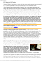
Testing or Repairing Bad Fuel Injection Relay. I had a similar no-restart
problem on my '89 780, and the problem was, in fact, the fuel injection relay. Try
this. If the car quits and won't restart, try banging your fist on the left side of
console, at about ash tray height while cranking the engine. If it starts, the relay is
probably flaky. It sounds weird, but that's how I found my problem. If you want to
be more sophisticated, use a volt meter to check the voltage to ground at the
injection ballast resistors. You should see 12 volts when you turn the key on. If
not, thump the console. If the voltage comes on, it's the fuel injection (pump)
relay.
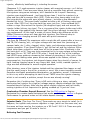
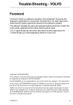
[Response 2:] The Bosch relays can be resoldered very easily by anyone handy
with a soldering iron and soldering gun. And a little experience. Remove the plastic
relay cover and examine the foil side of the printed circuit board (on the flip side
from the electronic components).With a magnifying glass
you'll probably see the solder cracked, crystallized, and
overheated around the heavy connections to the actual
relay -- they look like little buttons coming through the
silvery solder. I use a soldering gun the heat & resolder
these heavy connections, and a small 25 Watt iron for
the other connections. Be very careful not to form a
solder bridge between adjacent foil traces. You might
consider drilling several holes in the plastic case for ventilation -- a good idea.
[Tips from John O] What I've seen occur with some of those relays isn't cracks but
sticking contacts, like any electrical contacts do with time and use. That's why I
just replace the relay. Otherwise, try soldering it and filing the contacts if possible
file:///C|/Users/Steve/Documents/Volvo%20FAQ%20Updated/EngineFuelinjection.html[01/13/14 10:04:34 PM]
Engine: Fuel Injection
but for $50, I don't think it's worth the gamble in my humble opinion. Also look at
the terminal at the relay box for discoloration as they sometimes get so hot that
they melt the plastic. [Editor] If you've replaced the relay, make sure it is the
correct application.
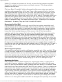
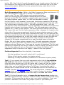
Radio Suppression Relay. [What is the Radio Suppression Relay and where is it?]
The radio suppression relay (as it's called) is in actually a fuel
injector relay. The pre 1986 injectors were supplied constant +
power to one terminal and supplied a timed ground to the other
terminal via the ECM. The constant + power used to come from the
fuel pump/injection system relay. In 1986 Volvo decided to isolate
the fuel injector circuit because of some radio interference created by the pulsing
circuit around the relay tray inside the passenger compartment and near the radio.
The solution was to energize a relay - the radio suppression relay - with the
pump/system relay feed instead of using the passenger compartment-mounted fuel
injection relay to power the injectors directly. The radio suppression relay then
supplies the + power to the injectors. The timed ground still comes from the ECM.
The reason Alex can't find his radio suppression relay is because it's located on the
other side of the engine compartment behind the power steering reservoir, (relay
closest to the engine of the two relays mounted there Alex). For the most part the
non-turbo engines had the radio suppression relay mounted on the right side (pass)
of the engine compartment on or near the coolant reservoir or near the ABS unit.
The turbo engines had the radio suppression relay mounted on the left side
(drivers) of the engine compartment on or near the shock tower or the inner
fender. Not set in stone just as a general rule. The radio suppression relay was
used from model years 1987 until 1995 on almost all LH injected 4 cyl and V6
engines and many Regina cars. There may be a couple of exceptions. The 5cyl and
straight 6cyl engines do not use one. When it's bad or missing, the radio will work
fine, but the engine will not run. Remember even though it's called a radio
suppression relay it's function is to supply + power to the fuel injectors.
Problem diagnosis:When this relay fails, it can cause:
Hot start problems (car won't restart until it cools down)
Failure of fuel injector system (no injector pulses)
Backfiring or balky acceleration (insufficient or inconsistent injector pulses)
Test 1. If you suspect that your radio suppression relay is faulty try switching
the leads with the electric cooling fan relay if your car is so equipped. These
relays are often identical up to the 940 series and in many car lines are located
right next to the radio suppression FI relay. If your fan stops and your engine
starts, then you've isolated the problem. In 940 cars, the cooling fan relay is
different and is located behind the left front headlamp and will not substitute for
the RSR. See also Hot Start Problems. The usual relay failure is caused by solder
cracking which can be repaired. Note that in cooler climates, the electric fan may
be so infrequently used that the coolant fan relay is corroded and broken.
Test 2. A further diagnostic test is to jumper the two larger wires leading into
the radio suppression relay connector. If the fan starts, you've jumpered the wrong
connector. If the engine then is able to start, your relay is defective. If not, your
problem is elsewhere. Don't leave the jumper in place or your battery will
file:///C|/Users/Steve/Documents/Volvo%20FAQ%20Updated/EngineFuelinjection.html[01/13/14 10:04:34 PM]
Engine: Fuel Injection
discharge: this is for testing only.
Diagnostic Help and Limp-Home Device. [Bill Bithell] Take an old RSR relay,
open it up, and solder a heavy jumper between pins 3 & 4 to make an emergency
jumper to plug in the RSR socket. Good for testing and limping home. Paint it
orange to distinguish it from your normal relays. Don't use this as a permanent
relay.
Oxygen Sensor Diagnosis.
Oxygen Sensor Simple Diagnostics. [Herb Goltz] You don't need to remove the
sensor or jack the car up to check it. You need a digital voltmeter with an
impedance of at least 10 megohms to prevent damage to the ECU. First, trace the
leads from the sensor up to the firewall. For your model there will be 3 wires, two
of which go into a connector. They are just wiring for a heater to get your sensor
up to temp quicker. The wire you are interested in is a single shielded wire-depending on the model, it will have various colors. There will be a spade
connector underneath a bullet shaped black cover. Just pull the cover back. Warm
the car up to operating temperature. Uncover the spade connector-- leave all the
wires plugged in and the car running. Set your multimeter to DC volts, and the
range to <2V. Ground the negative probe of the multimeter to chassis ground (like
the strut tower) and the positive to the connection at the O2 sensor. You should
see voltages oscillating regularly from around 0.1-0.9V. If voltage is steady or zero
then you likely have a bad O2 sensor.
Oxygen Sensor Problem Diagnostics.
a. Bosch Diagnostics: Test for a rich mixture as follows:
Disconnect the sensor lead to the control unit.
Run the engine at 2500 rpm
Artificially enrich the fuel mixture on electronic fuel injected engines by
removing and plugging the vacuum line to the fuel pressure regulator.
If the voltmeter rapidly reads .9 volts, then the oxygen sensor is correctly
sensing a rich mixture. But, if the voltmeter responds sluggishly, or if it stays
below .9 volts, try running it at 3,000 rpm for a few minutes, then check
again. No improvement means you buy a new sensor.
Test for a lean mixture as follows:
Induce a small vacuum leak
If the voltmeter rapidly drops to .2 volts or below in less than a second, then
the oxygen sensor is correctly measuring the lean mixture. But if the
voltmeter responds sluggishly, of if it stays above .2 volts, give it the 3,000
rpm treatment and try again.
If no improvement, then the sensor should be replaced.
Test dynamic performance as follows:
Reconnect the sensor lead and tap your meter into the signal wire
Set the mixture to specification.
file:///C|/Users/Steve/Documents/Volvo%20FAQ%20Updated/EngineFuelinjection.html[01/13/14 10:04:34 PM]
Engine: Fuel Injection
Run the engine at 1500 rpm.
You should see rapidly changing readings that average somewhere around .5
volt as the computer keeps adjusting the blend. The sensor output should
fluctuate around .5 volts. If it doesn't, replace the sensor. Deciding whether or
not response is slow enough to justify replacement requires some judgment. A
common rule of thumb for minimum activity is eight trips across the rich/lean
line in ten seconds, and sometimes you can find specs for cross-counts.
Regina Diagnostics: [Bruce Young] The above apply, but know that:
The white and red wires in one connector are the heater circuit; the black wire
in second connector is the signal.
Red is +12V; white is ground
Black (connected w/engine running) should cycle rapidly between 0.1V and
1.2V
Black (disconnected w/engine running) should after a while rise to 1.2V
Replacement is NGK 25002, not a "generic" sensor.
For more information, see the FAQ Engine Sensor section on Oxygen Sensors.
Air Mass Meter Diagnosis.
Setting Base Idle and Mixture on Bosch LH2.2 Cars. See the FAQ section above
for tips on base specifications.
Simple Functional Diagnosis of AMM. [Editor] The classic test of AMM failure is
to disconnect it; if the car runs better, then the AMM is at fault. But here are the
OEM tests per the OEM manual for Bosch 2.4 (the-016 AMM):
1. Check the ground point of the AMM:
ignition off; disconnect AMM
connect ohmmeter between ground and terminal 1
should be 0 ohms
if not 0 ohms, check the ground point on the intake manifold
2. Check signal from AMM:
clean off sensor connector, removing any corrosion
start engine
connect voltmeter between ground and back of terminal 3 on back of
connector
should read approx 2.3 volts.
if not approx. 2.3 volts, substitute another AMM
Testing AMMs and Calibration. This is a response from Python Injection
(rebuilders of AMMs) to a question about testing AMMs.
From: Joe Evert, Director of Engineering, Python Injection
Subject: Re: Technical Question about AMM
The reason the OEM doesn't give a test procedure for calibrating the air mass
meter is two fold. First of all BOSCH Hot Wire Air Mass sensors are not linear
file:///C|/Users/Steve/Documents/Volvo%20FAQ%20Updated/EngineFuelinjection.html[01/13/14 10:04:34 PM]
Engine: Fuel Injection
devices like a throttle position sensor. The output does not change the same
amount for a given air change. To make it short, most linear sensors will give you
say... 1 volt for 100cfm air flow, 2 volts for 200cfm air flow, 3 volts for 300cfm
airflow etc. This is a linear device. Bosch hot wire sensors are not like this. They
change a great deal at low air flows but once the air flow increases past a certain
point, say 50% of what the engine can draw, they change very little. This makes
the sensor very accurate at low to moderate air flows and good enough at high air
flows. Just a small amount of inaccuracy at low RPM and the vehicle will run
terrible. If the voltage for a given air flow is off by 100 milli volts at low RPM the
car will barely run. At high RPM A 100 milli volt deviation will not even be noticed.
Because of this it makes it next to impossible for the technician to accurately
diagnose the air mass in the field. We use a calibrated flow bench that measures
the exact CFM air flow to then compare the voltage to. This is not practical in the
field because temperature, altitude, humidity and the mechanical condition of the
engine will affect how much air the engine is drawing in. So just to say that the Air
mass should have xx.xx volts at idle would be completely false since all these
parameters must be accounted for. Also even if a range is given just a small
amount of deviation in the output causes poor performance.
So what are you to do? For on-vehicle diagnoses the best way is just unplug it at
idle; if the vehicle runs better it is most likely bad. This is because if the air flow
sensor is off voltage at high RPM it will also be off at idle. Also if you are
experiencing repeated failures you probably have a defective air box thermostat.
This little thermostatic bulb is located in the air filter box and controls the hot air
into the engine. When this fails it fails in hot air mode and routes hot air from
around the manifold into the air intake. This will destroy the air mass meter in no
time.
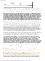
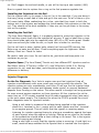
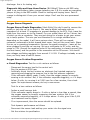
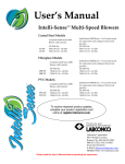
Contaminants on Heated Sensor Wire. [Editor] It is
rare but possible to see contaminants build up on the
tiny sensor wires inside the Bosch air mass sensor due
to dirt, spider webs, a disintegrating air filter, etc. In
some instances, the hot burn-off cycle will not remove
these contaminants. When this happens, it skews the
ECU transfer function such that the MAF overestimates
airflow at idle (causes the fuel system to go rich) and
underestimates airflow at high airflow (causes the fuel system to go lean). This
means that Long Term Fuel Trim will learn lean (negative) corrections at idle and
rich (positive) corrections at higher airflow and may be the cause of high NOX
readings on test. To remedy, spray the sensor wires inside very carefully with CRC
Air Mass Sensor cleaner to remove them, then reinstall and turn the engine on and
off to activate the burnoff cycle. Don't use carb or brake cleaners which will
damage the plastics.
Cleaning Mass Air Flow Meters. [John Roberson] Post-1996 960/90 cars use a
hot film mass air flow sensor. This can become dirty. To clean it, follow the
instructions. [Lyle Domico] Cleaning the AMM sensor wires, despite their automatic
cleaning cycle, improved my 240's power and economy. Here's how to do it using
CRC Mass Air Sensor spray cleaner (~$7 at auto parts stores):
1. Remove the AMM from the car to do the best cleaning.
file:///C|/Users/Steve/Documents/Volvo%20FAQ%20Updated/EngineFuelinjection.html[01/13/14 10:04:34 PM]
Engine: Fuel Injection
2. When spraying, use the extension nozzle, and press the button full down to
get max pressure blast. Don't be shy. This stuff dries quick.
3. DON'T TOUCH the sensor wire.
[Editor] Some anecdotes have been collected at Brickboard about AMM's failing
after cleaning with spray cleaners.
Replacing Air Mass Meters. [Editor] Bosch OEM is clearly the highest quality.
Good reports have been received at Brickboard on remanufactured AMMs. The
cheap aftermarket units found on EBay are reported to run terribly.
ECU Failure. See the FAQ file with much more information about symptoms,
diagnoses, and repair.
Carbon Vapor Canister. The vapor canister, a cylinder about eight inches long
and five in diameter, absorbs fuel vapors from the fuel system to control emissions.
It can have a single diaphragm and single valve on top, or dual purge type with
two ports, one of which is not used. Volvo uses only one of the ports. If this fails,
you may smell fuel vapors under the hood; however, the unit usually does not fail
except through cracking after a collision. If you smell vapors, more likely is a
cracked rubber hose or port cap.
740/940 Series Vapor Canister Notes. This canister is the same GM Rochester
carbon canister used on about 16 billion other cars, except Fords and Asian cars.
Tell a parts guy that you have a mid-80s Chevy or Chrysler. I don't have the
number for the type with the single diaphragm and valve on top. The dual purge
type can use Standard Motor Parts CP1014 or Airtex 4B1002 to replace AC part
215150. Just use the nipples that match your original one. [Jay Simkin] If you
need OEM, the part number is 1276694. The cost is about $200 from the dealer.
960/90 Series Vapor Canister Notes. See the FAQ link for more information.
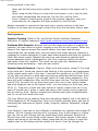
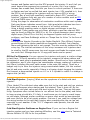
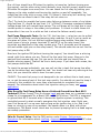
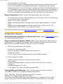
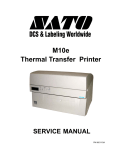
Vacuum Line Notes. The vacuum
lines to the vapor canister are
printed on the vacuum diagram
under the hood. They emerge from
the throttle body, enter a shrink
wrap sleeve and proceed to the
canister. See the diagram to the
right for a schematic (B230F
shown, B230FT similar depending
on model year).
file:///C|/Users/Steve/Documents/Volvo%20FAQ%20Updated/EngineFuelinjection.html[01/13/14 10:04:34 PM]
Engine: Fuel Injection
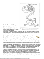
Air Box Thermostat Change.
Note: Non-turbo cars have a
thermostat inside the air box that
shifts air intake from heated air to
cold air when the engine is warm.
This is done to improve
combustion at cold starts. Early turbos also had this thermostat, ending around
1988; later turbos do not. When this thermostat fails, it locks in the "hot air only"
position and can fry your air mass meter.
[Inquiry:] Can I change the air box thermostat in 7xx/9xx cars with an
integral lower air box/thermostat combination? [Response: Steve
Seekins] You can change just the thermostat element on any of the
cars that are equipped with it. You only need to change the flapper if
the hinges are worn or broken, or if the gaskets are destroyed. See below for
instructions on thermostat removal on 90+ cars with integral air boxes. [Editor]
You can buy a replacement thermostat from an aftermarket supplier for about $10.
[Editor] Spring is an appropriate time to test the function of your airbox thermostat
and change it if needed. The thermostat can seize, allowing hot air to enter the air
mass meter and dramatically reducing its lifetime. Note that many turbos do not
have these thermostats since the turbo itself adds heat to the intake air.
[Tech Tip from Walt Posluszny] I stuck a wireless household thermometer in the
airbox of our 95 960 (152,820 miles) today. The outside temp was 70F and the
temp in the airbox steadily rose while we were driving up a fairly constant 4
percent grade for 4.5 miles. Halfway up the road the thermometer registered 160F
before it literally melted down. I pulled the air mixing box, and jammed the air
door to open/cool air, replaced the still-operable remote thermometer, and took it
file:///C|/Users/Steve/Documents/Volvo%20FAQ%20Updated/EngineFuelinjection.html[01/13/14 10:04:34 PM]
Engine: Fuel Injection
up the same grade. The temperature declined to 73.5F in the airbox even though I
was climbing the same 4% grade. Lesson: check your airbox thermostat and
replace it if needed.
To test the thermostat:
1. Remove the air intake pipe from the grill hole to the air box extension.
2. Start your engine. As the engine warms up, the flapper inside the hole should
move to the fully closed position in moderate to warm weather. If it does not,
then you need to change the thermostat. See the FAQ section for test
temperatures and flapper positions.
To change the thermostat in a 90+ car with the assembly inside the airbox :
1. Remove the air box from the car.
2. Spray PBlaster around the air pipe joint where the extension tube enters the
airbox. This joint will be very tight.
3. Gently depress the tabs and twist to loosen and remove the extension tube
assembly holding the thermostat mechanism. Be careful that you don't crack
the tube or the box while working on it.
4. Once this is free, you will be able to see and access the brass thermostat.
5. Depress the spring using either plier jaws or a two-pringed body clip remover
tool. Push this down sufficiently to expose the thermostat piston rod.
6. Pop the thermostat out and insert the new one in its place. Make sure the rod
goes in the hole at the top of the spring.
7. Make sure the flapper assembly operates correctly.
8. Clean everything up, lube the assembly with non-silicone lube, and reassemble.
The only risks are being a little too brutal and cracking the plastic, or breaking an
air box clip on removal. Be careful.
Engine Storage/Used Engine Notes.
[Tip from Linder Injector Services] If you have installed a salvage yard engine,
depending on how long it has sat it may have clogged injectors or fuel rail. The
ones that I have seen require the injectors to be serviced off the engine. This will
ensure that the inlet filters are clean (new) and their flow is correct with the
appropriate spray pattern. The rail was flushed or ultrasonically cleaned. The
pressure regulator had to be replaced on a couple of systems due to a lot of
sediment. Most of the time this was a simple process that was fairly inexpensive.
Volvo Maintenance FAQ for 7xx/9xx/90 Cars
file:///C|/Users/Steve/Documents/Volvo%20FAQ%20Updated/EngineFuelinjection.html[01/13/14 10:04:34 PM]