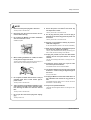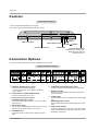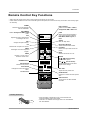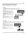
1
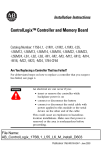
PLASMA MONITOR
OWNER’S MANUAL
MODELS: MP-42PZ44/44H/45M/45V
MP-42PZ44A/44HA/45MA/45VA
MP-42PZ44B/44HB/45MB/45VB
MP-42PZ44K/44HK/45MK/45VK
MP-42PZ44R/44HR/45MR/45VR
MP-42PZ44S/44HS/45MS/45VS
MP-42PZ90/90H/91M/91V
MP-42PZ90A/90HA/91MA/91VA
MP-42PZ90B/90HB/91MB/91VB
MP-42PZ90K/90HK/91MK/91VK
MP-42PZ90R/90HR/45MR/91VR
MP-42PZ90S/90HS/91MS/91VS
Please read this owner’s manual thoroughly before operating
the Monitor.
Retain it for future reference.
Record model number and serial number of the Monitor.
See the label attached on the back of the Monitor and relate
this information to your dealer if you ever require service.
Model Number :
Serial Number :
P/NO : 3828VA0415A a (RF03GA)
Safety Instructions
Safety Instructions
* Safety instructions have two kinds of information, and each meaning of it is as below.
WARNING The violation of this instruction may cause serious injuries and even death.
NOTES
The violation of this instruction may cause light injuries or damage of the
product.
Take care of danger that may happen under specific condition.
WARNING
W
1. Do not place the Monitor in direct sunlight or near
heat sources such as heat registers, stove and so
on.
This may cause a fire or could give an electric shock.
7. Do not place heavy objects on the Monitor.
This may cause a fire.
2. Do not use the Monitor in damp place such as a
bathroom or any place where it is likely to get
wet.
This may cause a fire or could give an electric shock.
3. Bend antenna cable between inside and outside
building to prevent rain from flowing in.
This may cause water damaged inside the Monitor and could
give an electric shock.
4. Earth wire should be connected.
- If the earth wire is not connected, there is possible a danger
of electric shock caused by the current leakage.
- If grounding methods are not possible, a separate circuit
breaker should be employed and installed by a qualified
electrician.
- Do not connect ground to telephone wires, lightning rods or
gas pipe.
Power
supplier
Short-circuit
breaker
5. Do not placing anything containing liquid on top
of the Monitor.
This may cause a fire or could give an electric shock.
2 Plasma Monitor
6. Do not insert any object into the exhaust vent.
This may cause serious injury to a child or adult.
8. Do not use water the Monitor while cleaning.
This may cause damaged the Monitor or could give an electric shock.
9. In case of smoke or strange smell from the
Monitor, switch it off ,unplug it from the wall outlet and contact your dealer or service center.
This may cause a fire or could give an electric shock.
10. Do not attempt to service the Monitor yourself.
Contact your dealer or service center.
This may cause damaged the Monitor or could give an electric shock.
11.During a lightning thunder, unplug the Monitor
from the wall outlet and don’t touch an antenna
cable.
This may cause damaged the Monitor or could give an electric shock.
Safety Instructions
NOTE
1. Never touch the power plug with a wet hand.
This may cause an electric shock.
8. Ensure the power cord doesn’t trail across any
hot objects like a heater.
This may cause a fire or an electric shock.
2. Disconnect from the mains and remove all connections before moving.
3. Do not place the Monitor in a built-in installation
such as a bookcase or rack.
9. Do not plug when the power cord or the plug is
damaged or the connecting part of the power outlet is loose.
This may cause a fire or an electric shock.
Ventilation required.
10. Dispose of used batteries carefully to protect a
child from eating them.
In case that it eats them, take it to see a doctor immediately.
11. When moving the Monitor assembled with speakers do not carry holding the speakers.
This may cause the Monitor to fall, causing serious injury to a
child or adult, and serious damage to the Monitor.
4. When installing the Monitor on a table, be careful
not to place the edge of its stand.
This may cause the Monitor to fall, causing serious injury to a
child or adult, and serious damage to the Monitor.
12. Unplug this product from the wall outlet before
cleaning. Do not use liquid cleaners or aerosol
cleaners.
This may cause damaged the Monitor or could give an electric shock.
13. Contact the service center once a year to clean
the internal part of the Monitor.
Accumulated dust can cause mechanical failure.
14. The distance between eyes and the screen should
be about 5 ~ 7 times as long as diagonal length of
the screen.
If not, eyes will strain.
5. Do not place an outside antenna in the vicinity of
overhead power lines or other electric light or
power circuits.
This may cause an electric shock.
6. There should be enough distance between an outside antenna and power lines to keep the former
from touching the latter even when the antenna
falls.
15. Unplug the Monitor from the wall outlet when it is
left unattended and unused for long periods of
time.
Accumulated dust may cause a fire or an electric shock from
deterioration or electric leakage.
16. Only use the specified batteries.
This make cause damaged the Monitor or could give an electric shock.
This may cause an electric shock.
7. Do not pull the cord but the plug when unplugging.
This may cause a fire.
Owner’s Manual 3
Contents
Contents
Safety Instructions . . . . . . . . . . . . . . . . . . . . . . . . . . . . .2~3
Introduction
Controls and Connection Options . . . . . . . . . . . .6
Remote Control Key Functions . . . . . . . . . . . . . .7
Installation
Installation Instruction . . . . . . . . . . . . . . . . . . . .9~10
External Equipment Connections . . . . . . . . . .11~14
VCR Setup . . . . . . . . . . . . . . . . . . . . . . . . . . . .11
Cable TV Setup . . . . . . . . . . . . . . . . . . . . . . . .11
External A/V Source Setup . . . . . . . . . . . . . . . .12
DVD Setup . . . . . . . . . . . . . . . . . . . . . . . . . . . .12
DTV Setup . . . . . . . . . . . . . . . . . . . . . . . . . . . .12
PC Setup . . . . . . . . . . . . . . . . . . . . . . . . . .13~14
Operation
Turning on the Monitor . . . . . . . . . . . . . . . . . . . . .15
Menu Language Selection . . . . . . . . . . . . . . . . . .15
Picture Menu Options
APC (Auto Picture Control) . . . . . . . . . . . . . . . .16
Manual Picture Control . . . . . . . . . . . . . . . . . . .16
Auto Color Temperature Control . . . . . . . . . . . .16
Manual Color Temperature Control . . . . . . . . . .16
Sound Menu Options
DASP (Digital Auto Sound Processing) . . . . . . .17
Manual Sound Control . . . . . . . . . . . . . . . . . . .17
AVL (Auto Volume Leveler) . . . . . . . . . . . . . . . .17
Timer Menu Options
Clock Setup . . . . . . . . . . . . . . . . . . . . . . . . . . .18
On/Off Timers Setup . . . . . . . . . . . . . . . . . . . . .18
Auto Off . . . . . . . . . . . . . . . . . . . . . . . . . . . . . .18
Sleep Timer . . . . . . . . . . . . . . . . . . . . . . . . . . .18
Special Menu Options
Key Lock . . . . . . . . . . . . . . . . . . . . . . . . . . . . .19
ISM Method . . . . . . . . . . . . . . . . . . . . . . . . . . .19
Low power . . . . . . . . . . . . . . . . . . . . . . . . . . . .20
Menu Rotation For Vertical Viewing . . . . . . . . . .20
Screen Menu Options
Auto Adjustment . . . . . . . . . . . . . . . . . . . . . . . .21
Setting Picture Format . . . . . . . . . . . . . . . . . . .21
Picture Size Zoom . . . . . . . . . . . . . . . . . . . . . .21
Adjusting Horizontal/Vertical Position . . . . . . . .22
Manual Configure . . . . . . . . . . . . . . . . . . . . . . .22
Screen Adjustments . . . . . . . . . . . . . . . . . . . . .22
Initializing . . . . . . . . . . . . . . . . . . . . . . . . . . . . .22
Luminance Noise Reduction . . . . . . . . . . . . . . .23
Selecting Wide VGA mode . . . . . . . . . . . . . . . .23
Split Zoom . . . . . . . . . . . . . . . . . . . . . . . . . . . .23
PIP (Picture-in-Picture) Feature
Watching PIP . . . . . . . . . . . . . . . . . . . . . . . . . .24
Swapping the PIP . . . . . . . . . . . . . . . . . . . . . . .24
Moving the PIP . . . . . . . . . . . . . . . . . . . . . . . . .24
Selecting an Input Signal Source for PIP . . . . . .24
PIP Aspect Ratio . . . . . . . . . . . . . . . . . . . . . . . .24
Double Window Setup Options
Watching Double Window . . . . . . . . . . . . . . . . .25
Sub Picture Size Adjustment . . . . . . . . . . . . . . .25
Swapping the Double Window . . . . . . . . . . . . .25
Selecting a Source for the Double Window . . . .25
External Control Device Setup . . . . . . . . . . . . . . . .26~31
IR Code
. . . . . . . . . . . . . . . . . . . . . . . . . . . . . . . . .32~33
Troubleshooting Checklist . . . . . . . . . . . . . . . . . . . . . .34
Specifications . . . . . . . . . . . . . . . . . . . . . . . . . . . . . . . .35
After reading this manual, keep it handy for future reference.
4 Plasma Monitor
Introduction
Introduction
What is a Plasma Display Panel (PDP)?
If voltage is applied to gas within glass panels, ultraviolet rays are produced and fused with a fluorescent substance. At that
instant, light is emitted. A Plasma Display is a next generation flat Display using this phenomenon.
160° - Wide angle range of vision
Your flat panel plasma screen offers an exceptionally broad viewing angle -- over 160 degrees. This means that the display is
clear and visible to viewers anywhere in the room.
Wide Screen
The screen of the Plasma Display is 42" so wide that your viewing experience is as if you are in a theater.
Multimedia
Connect your plasma display to a PC and you can use it for conferencing, games, and internet browsing. The Picture-in-Picture
feature allows you to view your PC and video images simultaneously.
Versatile
The light weight and thin size makes it easy to install your plasma display in a variety of locations where conventional TVs would
not fit.
The PDP Manufacturing Process: Why minute colored dots may be present on the PDP screen
The PDP (Plasma Display Panel) which is the display device of this product is composed of 0.9 to 2.2 million cells. A few cell
defects will normally occur in the PDP manufacturing process. Several minute colored dots visible on the screen should be acceptable. This also occurs in other PDP manufacturers' products and the tiny dots appearing does not mean that this PDP is defective.
Thus a few cell defects are not sufficient cause for the PDP to be exchanged or returned. Our production technology is designed
to minimize cell defects during the manufacture and operation of this product.
Cooling Fan Noise
In the same way that a fan is used in a PC computer to keep the CPU (Central Processing Unit) cool, the PDP is equipped with
cooling fans to cool the Monitor and improve its reliability. Therefore, a certain level of noise could occur while the fans are operating and cooling the PDP.
The fan noise doesn't have any negative effect on the PDP's efficiency or reliability. The noise from these fans is normal during the
operation of this product. We hope you understand that a certain level of noise from the cooling fans is acceptable and is not sufficient cause for the PDP to be exchanged or returned.
WARNING
TO REDUCE THE RISK OF FIRE AND ELECTRIC SHOCK, DO NOT EXPOSE THIS PRODUCT TO
RAIN OR MOISTURE.
Owner’s Manual 5
Introduction
Controls
Front Panel Controls
- This is a simplified representation of front panel.
Here shown may be somewhat different from your monitor.
INPUT
SELECT
ON/OFF
MENU
VOL.
E, D
Main Power Button
INPUT SELECT Button
Buttons
VOLUME (F,G) Buttons
MENU Button
Remote Control Sensor
Power Standby Indicator
Illuminates red in standby mode,
Illuminates green when the
Monitor is turned on
Connection Options
- Connection panels shown may be somewhat different from your monitor.
Back Connection Panel
R AUDIO L
( )L ( )
( )R( )
EXTERNAL SPEAKER
1
RS-232C INPUT
(CONTROL/SERVICE)
2
DVI INPUT
RGB INPUT
AUDIO INPUT
3
RGB OUTPUT
EXPANDED
INPUT
4
5
1. EXTERNAL SPEAKER (8 ohm output)
Connect to optional external speaker(s).
* For further information, refer to ‘Speaker & Speaker
Stand’ manual.
2. RS-232C INPUT (CONTROL/SERVICE) PORT
Connect to the RS-232C port on a PC.
3. DVI (Digital Visual Interface) INPUT/
RGB INPUT/AUDIO INPUT JACKS
Connect the monitor output connector of a PC to the appropriate input port.
4. RGB OUTPUT JACKS
You can watch the RGB signal on another monitor, connect
RGB OUTPUT to another monitor’s PC input port.
5. EXPANDED INPUT
Connect the monitor to the PDP Tuner with the tuner box
cable.
6 Plasma Monitor
AUDIO INPUT
Y
PB
PR
R AUDIO L (MONO)
COMPONENT INPUT REMOTE S-VIDEO
CONTROL
6
7
VIDEO
INPUT
8
AUDIO INPUT
AC INPUT
9
6. COMPONENT INPUT/AUDIO INPUT JACKS
Connect a component video/audio device to these jacks.
7. REMOTE CONTROL
Connect your wired remote control to the remote control
port on the Monitor.
8. S-VIDEO INPUT
Connect S-Video out from an S-VIDEO VCR to the S-VIDEO
input.
AUDIO/VIDEO INPUT JACKS
Connect audio/video out from external equipment to these
jacks.
9. POWER CORD SOCKET
This Monitor operates on an AC power. The voltage is indicated on the Specifications page. Never attempt to operate
the Monitor on DC power.
Introduction
Remote Control Key Functions
- When using the remote control, aim it at the remote control sensor on the monitor.
- Under certain conditions such as if the remote IR signal is interrupted, the remote control may not function. Press the key again
as necessary.
POWER
Switches the monitor between
ON and STANDBY.
INPUT SELECT
Selects source: Video, S-Video,
Component, RGB, or DVI mode.
MULTIMEDIA
Selects: Component, RGB, or DVI
mode.
APC
Adjusts the factory preset picture
according to the room.
ARC
Changes the picture format.
PIP
Switches the sub picture on and off.
POWER
MULTIMEDIA
INPUT SELECT
APC
DASP
ARC
SLEEP
PIP
DW
SWAP
PIP INPUT
MENU
SWAP
Exchanges main and sub picture
images.
DASP
Selects the sound appropriate to
your viewing program character:
Flat, Music, Movie, Sports, or
VOL
CH
ENTER
MUTE
SPLIT ZOOM
Enlarge the screen with regular
ration.
PIP INPUT
Selects the input mode for the sub
picture.
ENTER
1
2
3
4
5
6
7
8
9
WIN.POSITION
0
WIN.SIZE
SPLIT ZOOM
ZOOM -
ZOOM +
A.PROG MEMORY/ERASE PIP CH
Not functional
DW (Double Window)
Selects Double Window mode.
MUTE
Switches the sound on or off.
CH
WIN.POSITION
Moves the sub picture.
SLEEP
Sets the sleep timer.
VOL
MENU
Displays on screen menus.
Exits the current menu.
NUMBER buttons
User.
CAPTION
FAV CH
STOP
REW
PIP CH
MTS
POWER
P/STILL
REC
PLAY
FF
CH D / E (Channel button)
Selects menu options.
VOL F / G (Volume button)
Increases/decreases sound level.
Adjusts menu settings.
WIN. SIZE
Adjusts the sub picture size.
ZOOM-/ZOOM+
Enlarges or reduces the main picture
size.
VCR BUTTONS
Control some LG video cassette
recorders.
Installing Batteries
• Open the battery compartment cover on the back side and
insert the batteries with correct polarity.
• Install two 1.5V batteries of AAA type. Don’t mix used batteries
with new batteries.
Owner’s Manual 7
Installation
Installation
Ensure that the following accessories are included with your plasma display. If an accessory is missing, please contact the dealer
where you purchased the product.
POWER
1.5V
1.5V
SLEEP
Batteries
DASP
PIP ARC
PIP
TWIN PICTURE
VOL
Owner’s Manual
INPUT SELECT
APC
ARC
SUB INPUT
SWAP
MENU
BNC-RCA adapter
MUTE
OK
1
2
4
5
7
8
VOL
3
6
9
0
POWER
STOP
P/STILL
REW
PLAY
FF
REC
WIN.SIZE WIN.POSITION SPLIT ZOOM
ZOOM -
ZOOM +
Remote Control
Power Cord
D-sub 15 pin cable
DVI-D Cable
Option Extras
-
Optional extras can be changed or modified for quality improvement without any notification new optional extras can be added.
Contract your dealer for buying these items.
Tilt wall mounting bracket
Wall mounting bracket
Audio cables
Video cables
Vertical wall mounting bracket
(MP-42PZ45M/45V/91M/91V
series models only)
Ceiling mounting bracket
MP-42PZ90/90H/91M/91V
series models only
MP-42PZ44/44H/45M/45V
series models only
Desktop stand
Desktop stand
Speakers
Desktop
Speaker stand
Speakers
8 Plasma Monitor
Floor type stand
Floor type
Speaker stand
Desktop
Speaker stand
Installation
Installation Instructions
• The Monitor can be installed in different ways such as on a wall, or on a desktop etc.
• Install this monitor only in a location where adequate ventilation is available.
• It is recommended that MP-42PZ44/45V/90/91V series models only be used at an altitude of less than 3281 feet (1000m)
to get the best quality picture and sound.
• It is recommended that MP-42PZ44H/45M/90H/91M series models only be used at an altitude of less than 6561 feet (2000m)
to get the best quality picture and sound.
GROUNDING
Power
Supply
Ensure that you connect the grounding / earth wire to prevent possible
electric shock. If grounding methods are not possible, have a qualified
electrician install a separate circuit breaker. Do not try to ground the
unit by connecting it to telephone wires, lightening rods, or gas pipes.
yyyyyy
;;;;;;
yyyyyy
;;;;;;
yyyyyy
;;;;;;
yyyyyy
;;;;;;
yyyyyy
;;;;;;
Short-circuit
Breaker
Wall Mount Installation
For proper ventilation, allow a clearance of 4” on each
side and 2” from the wall. Detailed installation instructions are included from your dealer in the optional Wall
Mounting Bracket Installation and Setup Guide.
2 inches
4 inches
4 inches
4 inches
4 inches
Desktop Pedestal Installation
For proper ventilation, allow a clearance of 4” on each
side and the top, 2.36” on the bottom, and 2” from the
wall. Detailed installation instructions are included in the
optional Desktop Stand Installation and Setup Guide, see
your dealer.
2 inches
4 inches
4 inches
4 inches
2.36 inches
Owner’s Manual 9
Installation
Installation Instructions continued
Wall Mount: Vertical
Vertical installation (MP-42PZ45M/45V/91M/91V series models only)
Detailed installation instructions are included in the
optional Vertical Wall Mounting Bracket Installation and
Setup Guide, see your dealer.
NOTE: When installing the monitor vertically, the front
panel controls must be in the left side position.
When installing the monitor vertically, you
have to change the OSD (On Screen Display)
display mode so that the menus will appear
correctly and also to protect the monitor from
overheating (Refer to P. 20).
10 Plasma Monitor
Installation
External Equipment Connections
NOTE: All cables shown are not included with the plasma display.
VCR Setup
- To avoid picture noise (interference), leave an adequate distance between the VCR and Monitor
- Use the ISM Method feature to avoid having a fixed image remain on the screen for a long period of time. Typically a frozen still
picture from a VCR. If the 4:3 picture format is used; the fixed image may remain visible on the screen.
How to connect
1. Connect the provided BNC-RCA adapter to the monitor’s
VIDEO INPUT.
2. Connect the audio and video cables from the VCR's output
jacks to the monitor input jacks, as shown in the figure. When
connecting the monitor to a VCR, match the jack colors: (Video
= yellow, Audio Left = white, and Audio Right = red).
R AUDIO L
AUDIO INPUT
Y
PB
PR
R AUDIO L (MONO)
COMPONENT INPUT REMOTE S-VIDEO
CONTROL
VIDEO
INPUT
AUDIO INPUT
Mono VCR: Connect the video output cable from the VCR to
the VIDEO input on the monitor.
S-VIDEO VCR: Connect the S-Video output cable from the
VCR to the S-VIDEO input. (Note that S-Video yields higher
quality video).
How to use
1. Insert a video tape into the VCR and press PLAY on the VCR.
(Refer to the VCR owner’s manual.)
2. Use the INPUT SELECT button on the remote control to select
Video.
(If connected to S-VIDEO, select the S-Video external input
source.)
S-VIDEO
OUT
(R) AUDIO (L)
VIDEO
IN
VCR
Cable TV Setup
- After subscribing to a cable TV service from a local provider and installing a converter, you can watch cable TV programming.
The monitor cannot display TV programming unless a TV tuner device or cable TV converter box is connected to the Monitor.
- For further information regarding cable TV service, contact your local cable TV service provider(s).
How to connect
1. Connect the provided BNC-RCA adapter to the monitor’s
VIDEO INPUT.
2. Connect the audio and video cables from the cable box's output jacks to the monitor input jacks, as shown in the figure.
When connecting the monitor to a cable TV, match the jack
colors (Video = yellow, Audio Left = white, and Audio Right =
red).
R AUDIO L
AUDIO INPUT
Y
PB
PR
R AUDIO L (MONO)
COMPONENT INPUT REMOTE S-VIDEO
CONTROL
VIDEO
INPUT
AUDIO INPUT
How to use
1. Use the INPUT SELECT button on the remote control to
select Video.
2. Select your desired channel with the cable box remote control.
(R) AUDIO (L)
VIDEO
TV
VCR
RF
Cable
Cable Box
Owner’s Manual 11
Installation
External A/V Source Setup
How to connect
1. Connect the provided BNC-RCA adapter to the monitor’s
VIDEO INPUT.
2. Connect the audio and video cables from the external
equipment's output jacks to the monitor input jacks, as
shown in the figure. When connecting the monitor to external equipment, match the jack colors (Video = yellow, Audio
Left = white, and Audio Right = red).
R AUDIO L
AUDIO INPUT
Y
PB
PR
R AUDIO L (MONO)
S-VIDEO
COMPONENT INPUT REMOTE
CONTROL
VIDEO
INPUT
AUDIO INPUT
How to use
Camcorder
1. Use the INPUT SELECT button on the remote control to
select Video.
2. Operate the corresponding external equipment. Refer to
external equipment operating guide.
Video game set
R
AUDIO
VIDEO
L
DVD Setup
How to connect
R AUDIO L
AUDIO INPUT
Y
PB
PR
1. Connect the DVD video outputs to the COMPONENT (Y, PB, PR)
INPUT jacks and connect the DVD audio outputs to the AUDIO
INPUT jacks on the monitor, as shown in the figure.
2. If your DVD only has an S-Video output jack, connect this to the
S-VIDEO input on the monitor and connect the DVD audio outputs
to the AUDIO INPUT jacks, as shown in the figure.
R AUDIO L (MONO)
COMPONENT INPUT REMOTE S-VIDEO
CONTROL
VIDEO
INPUT
AUDIO INPUT
How to use
1. Turn on the DVD player, insert a DVD.
2. Use the INPUT SELECT button on the remote control to select
Component. (If connected to S-VIDEO, select the S-Video external input source.)
3. Refer to the DVD player's manual for operating instructions.
or
(R) AUDIO (L)
B
(R) AUDIO (L)
R
S-VIDEO
• Component Input ports
To get better picture quality, connect a DVD player to the component input ports as shown below.
Component ports of the
Monitor
DVD
Video output ports
of DVD player
PR
Y
PB
Y
Y
Y
Y
Pr
Pb
B-Y R-Y
Cb Cr
PB PR
DTV Setup
- To watch digitally broadcast programs, purchase and
connect a digital set-top box.
R AUDIO L
How to connect
1. Use the monitor’s COMPONENT (Y, PB, PR) INPUT,
RGB or DVI jack for video connections, depending on
your set-top box connector. Then, make the corresponding audio connections.
DVI INPUT
RGB INPUT
AUDIO INPUT
RGB OUTPUT
EXPANDED
INPUT
AUDIO INPUT
Y
PB
PR
R AUDIO L (MONO)
COMPONENT INPUT REMOTE S-VIDEO
CONTROL
VIDEO
INPUT
AUDIO INPUT
How to use
1. Turn on the digital set-top box. (Refer to the owner’s
manual for the digital set-top box.)
2. Use INPUT SELECT on the remote control to select
Component, RGB or DVI.
or
DVI-DTV OUTPUT
(R) AUDIO (L)
or
RGB-DTV OUTPUT
(R) AUDIO (L)
Digital Set-top Box
12 Plasma Monitor
(R) AUDIO (L)
B
R
Installation
PC Setup
- This Plasma display provides Plug and Play capability, meaning that the PC adjusts automatically to its settings. The monitor
sends configuration information (EDID) to the PC using the Video Electronics Standard Association (VESA) Display Data
Channel (DDC) protocol.
How to connect
1. To get the best picture quality, adjust the PC
graphics card to 800x600, 60Hz.
2. Use the monitor’s RGB INPUT or DVI (Digital
Visual Interface) INPUT port for video connections,
depending on your PC connector.
If the graphic card on the PC does not output analog and digital RGB simultaneously, connect only
one of both RGB INPUT or DVI INPUT to display
the PC image on the monitor.
If the graphic card on the PC does output analog
and digital RGB simultaneously, set the monitor to
either RGB or DVI; (the other mode is set to Plug
and Play automatically by the monitor.)
3. Then, make the corresponding audio connections.
If using a sound card, adjust the PC sound as
required.
( )R( )
( )L ( )
EXTERNAL SPEAKER
RS-232C INPUT
(CONTROL/SERVICE)
DVI INPUT
RGB INPUT
AUDIO INPUT
RGB OUTPUT
EXPANDED
INPUT
How to use
1. Turn on the PC and the monitor.
2. Turn on the display by pressing the POWER button on the monitor's remote control.
3. Use the INPUT SELECT button on the remote control to select RGB or DVI.
4. Check the image on your monitor. There may be noise associated with the resolution, vertical pattern, contrast or
brightness in PC mode. If noise is present, change the PC mode to another resolution, change the refresh rate to
another rate or adjust the brightness and contrast on the menu until the picture is clear. If the refresh rate of the PC
graphic card can not be changed, change the PC graphic card or consult the manufacturer of the PC graphic card.
NOTES
• Depending on the graphics card, DOS mode may not work if you use a DVI-I cable.
• Avoid keeping a fixed image on the monitor's screen for a long period of time. The fixed image may become permanently imprinted on the screen. Use the Orbiter screen saver when possible.
• The synchronization input form for Horizontal and Vertical frequencies is separate.
Owner’s Manual 13
Installation
Monitor Display Specifications (RGB-PC /DVI-PC Mode)
Resolution
640x350
720x400
640x480
848x480
852x480
14 Plasma Monitor
Horizontal
Vertical
Frequency(KHz) Frequency(Hz)
31.468
70.09
37.861
Resolution
85.08
800x600
Horizontal
Vertical
Frequency(KHz) Frequency(Hz)
35.156
56.25
37.879
60.31
31.469
70.08
48.077
72.18
37.927
85.03
46.875
75.00
31.469
59.94
53.674
85.06
35.000
66.66
49.725
74.55
37.861
72.80
48.363
60.00
37.500
75.00
56.476
70.06
43.269
85.00
60.023
75.02
31.500
60.00
54.348
60.05
35.000
70.00
63.995
70.01
37.500
75.00
67.500
75.00
31.500
60.00
1152x870
68.681
75.06
35.000
70.00
1280x960
60.000
60.00
37.500
75.00
1280x1024
63.981
60.02
832x624
1024x768
1152x864
Operation
Operation
- A inactive menu options aren’t available in this monitor.
It’s only available to connect with PDP Tuner (RP-BA50).
Turning on the Monitor
Turning on the Monitor just after installation
1. Connect power cord correctly.
2. Press the
ON/OFF button on the Monitor. At this moment, the Monitor is switched to standby
mode. Press the INPUT SELECT button on the Monitor or press the POWER, INPUT SELECT,
MULTIMEDIA button on the remote control to switch the Monitor on.
Turning on the Monitor (power cord is still connected)
1. If the Monitor was turned off with the
• Press the
ON/OFF button on the Monitor
ON/OFF button on the Monitor to turn the Monitor on.
2. If the Monitor was turned off with the remote control and the
ON/OFF button on the Monitor
• Press the
ON/OFF button on the Monitor and then press the INPUT SELECT button on the
Monitor. Or, on the remote control, press POWER, INPUT SELECT, or MULTIMEDIA to turn the
Monitor on.
Menu Language Selection
- The menus can be shown on the screen in the selected language. First select your language.
1. Press the MENU button and then use
2. Press the G button and then use D /
E
D
/
E
button to select the SPECIAL menu.
button to select Language.
3. Press the G button and then use D / E button to select your desired language.
From this point on, the on-screen menus will be shown in the language of your
choice.
SPECIAL
Language
G
English
Key lock
Español
ISM Method
Português
Low power
Français
Set ID
Caption / Text
4. Press the ENTER button to save.
Captions
OSD Rotate
MENU
Prev.
Owner’s Manual 15
Operation
Picture Menu Options
- Each adjustment for the Picture menu options doesn’t effect other input sources. Readjust Picture
menu options for each of the following sources.
• RGB (PC) / DVI (PC),
• RGB (DTV) / DVI (DTV) / Component (480p, 720p, 1080i)
• Video / S-Video / Component (480i)
APC (Auto Picture Control)
- APC adjusts the Monitor for the best picture appearance.
- When adjusting picture options (contrast, brightness, color, sharpness and tint) manually, APC automatically
changes to User.
1. Press the APC button repeatedly to select the picture appearance setup option as shown below.
Optimum
Soft
User
Clear
• You can also adjust APC in the PICTURE menu.
• Clear, Optimum, and Soft are preset for good picture quality at the factory and cannot be changed.
Manual Picture Control ( User option)
- You can adjust picture contrast, brightness, color, sharpness, and tint to the levels
you prefer.
PICTURE
APC
ACC
Color temp.
1. Press the MENU button and then use
D /E
button to select the PICTURE menu.
2. Press the G button and then use D / E button to select the desired picture option
(Contrast, Brightness, Color, Sharpness, Tint).
3. Press the G button and then use
F /G
button to make appropriate adjustments.
4. Press the ENTER button to save.
Contrast
80
G
Brightness 60
Color
50
Sharpness 50
Tint
0
MENU
Prev.
Auto Color Temperature Control
- To initialize values (reset to default settings), select the Normal option.
- When adjusting color temperature options (red, green, or blue) manually, ACC
automatically changes to User.
PICTURE
APC
G
ACC
1. Press the MENU button and then use
2. Press the
G
button and then use
D /E
D /E
button to select the PICTURE menu.
button to select ACC .
3. Press the G button and then use D / E button to select either Normal (Default),
Cool (Preset), Warm (Preset) or User (Manual Adjustment).
4. Press the ENTER button to save.
Normal
Cool
Color temp.
Contrast
80
Warm
Brightness
60
User
Color
50
Sharpness
50
Tint
0
MENU
Prev.
Manual Color Temperature Control ( User option)
- You can adjust red, green, or blue to any color temperature you prefer.
PICTURE
1. Press the MENU button and then use
D /E
button to select the PICTURE menu.
APC
ACC
2. Press the
G
button and then use
3. Press the
G
button and then use D
4. Use the
F /G
D /E
/E
button to select Color temp .
button to select Red, Green or Blue.
button to make appropriate adjustments.
• The adjustment range of Red, Green, and Blue is -20 ~ +20.
5. Press the ENTER button to save.
16 Plasma Monitor
G
Red
0
80
Green
0
Brightness
60
Blue
0
Color
50
Sharpness
50
Color temp.
Contrast
Tint
MENU
0
Prev.
Operation
Sound Menu Options
DASP (Digital Auto Sound Processing)
- This function lets you enjoy the best sound without any special adjustment because the Monitor has the appropriate
sound options based on the program content.
- When adjusting sound options (treble, bass, and balance) manually, DASP automatically changes to User.
1. Press the DASP button repeatedly to select the appropriate sound setup as shown below.
Flat
Music
Movie
Sports
User
• You can also adjust DASP in the SOUND menu.
• Flat, Music, Movie and Sports are preset for good sound quality at the factory and cannot be
changed.
Manual Sound Control ( User option)
- You can adjust sound treble, bass, and balance to the levels you prefer.
1. Press the MENU button and then use D
/E
2. Press the G button and then use
(Balance, Treble, Bass).
button to select the desired sound option
3. Press the
G
button and then use
D /E
button to select the SOUND menu.
SOUND
DASP
AVL
F /G
button to make appropriate adjustments.
4. Press the ENTER button to save.
Balance
0
Treble
50
Bass
50
MENU
G
Prev.
AVL (Auto Volume
Volume Leveler)
- AVL maintains an equal sound level; even if you change channels.
1. Press the MENU button and then use
D /E
button to select the SOUND menu.
2. Press the
G
button and then use
D /E
button to select AVL.
3. Press the
G
button and then use
D /E
button to select On or Off.
4. Press the ENTER button to save.
SOUND
DASP
G
AVL
Balance
0
Treble
50
Bass
50
MENU
On
Off
Prev.
Owner’s Manual 17
Operation
T imer Menu Options
Clock Setup
- If current time setting is erased by a power failure, if TV is unplugged or if the monitor is turned off with
the
ON/OFF button on the monitor, reset the clock.
1. Press the MENU button and then use
D /E
button to select the TIMER menu.
TIMER
2. Press the
G
3. Press the
4. Press the
button and then use
D /E
button to select Clock.
G
button and then use
D /E
button to set the hour.
G
button and then use
D /E
button to set the minutes.
G
Clock
-- :
--
Off timer
On timer
Auto off
5. Press the ENTER button to save.
MENU
Prev.
On/Off
On/Off Timers Setup
- Timer functions operate only if current time has been set.
- Off-Timer function overrides On-Timer function if they are set to the same time.
- The monitor must be in standby mode for the On-Timer to work.
1. Press the MENU button and then use
2. Press the
G
button and then use
D /E
D /E
TIMER
button to select the TIMER menu.
Clock
button to select Off timer or On timer.
Off timer
On timer
3. Press the G button and then use D / E button to select On.
• To cancel On/Off timer function, select Off.
G
button and then use
D /E
button to set the hour.
5. Press the
G
button and then use
D /E
button to set the minutes.
G
button and then use
On
Off
10 : 30
4. Press the
6. For only On timer function; Press the
sound level.
G
Auto off
Vol.
D /E
button to set
MENU
Prev.
7. Press the ENTER button to save.
Auto Off
Off
- If there is no input signal, the Monitor will turn off automatically after 10 minutes.
1. Press the MENU button and then use
D /E
2. Press the G button and then use
D /E
button to select Auto off.
3. Press the G button and then use
D /E
button to select On or Off.
TIMER
button to select the TIMER menu.
Clock
Off timer
On timer
Auto off
G
On
Off
4. Press the ENTER button to save.
MENU
Prev.
Sleep Timer
- The Sleep Timer turns the Monitor off at the preset time. Note that this setting is cleared when the monitor is turned off.
1. Press the SLEEP button repeatedly to select the number of minutes. First the
screen, followed by the following sleep timer options:
10, 20, 30, 60, 90, 120, 180, and 240 minutes.
zz
--- Min option appears on the
2. When the number of minutes you want is displayed on the screen, press the ENTER button. The timer begins to
count down from the number of minutes selected.
3. To check the remaining minutes before the monitor turns off, press the SLEEP or ENTER button once.
4. To cancel the Sleep Timer, press the SLEEP button repeatedly until
18 Plasma Monitor
30
Ch. TV 2
zz
--- Min appears.
Special Menu Options
Key Lock
- The monitor can be set up so that it can only be used with the remote control.
- This feature can be used to prevent unauthorized viewing by disabling the front panel controls.
- This Monitor is programmed to remember which option it was last set to even if you turn the monitor off.
1. Press the MENU button and then use
D /E
button to select the SPECIAL menu.
2. Press the
G
button and then use
D /E
button to select Key lock.
3. Press the
G
button and then use
D /E
button to select On or Off.
4. Press the ENTER button to save.
SPECIAL
Language
Key lock
On
G
Off
ISM Method
Low power
• With the KEY LOCK ON, the display ‘
button on the front panel is pressed.
W
Key lock’
appears on the screen if any
Set ID
Caption / Text
Captions
OSD Rotate
MENU
Prev.
ISM (Image Sticking Minimization) Method
- A frozen still picture from a PC/video game displayed on the screen for prolonged periods will result in a ghost
image remaining even when you change the image. Avoid allowing a fixed image to remain on the Monitor's
screen for a long period of time.
1. Press the MENU button and then use
2. Press the
G
button and then use
D /E
D /E
button to select the SPECIAL menu.
button to select ISM Method.
SPECIAL
Language
3. Press the G button and then use
wash, Orbiter, or Inversion.
D /E
button to select either Normal, White
• Normal:
If image sticking is never a problem, ISM is not necessary - set to Normal.
• White wash
White Wash removes permanent images from the screen. Note: An excessive permanent image may be impossible to clear entirely with White Wash. To return to
normal viewing, press the any button.
• Orbiter
Orbiter may help prevent ghost images. However, it is best not to allow any fixed
image to remain on the screen. To avoid a permanent image on the screen, the
screen will move every 1 minutes: Right → Right → Downside → Downside →
Left → Left → Upside → Upside.
• Inversion
Inversion will automatically invert the plasma display panel color every 30 minutes.
Key lock
ISM Method
G
Normal
Low power
White wash
Set ID
Orbiter
Caption / Text
Inversion
Captions
OSD Rotate
MENU
Prev.
4. Press the ENTER button to save.
Owner’s Manual 19
Operation
Special Menu Options continued
Low Power
- Low power reduces the plasma display power consumption.
1. Press the MENU button and then use
D /E
button to select the SPECIAL menu.
2. Press the
G
button and then use
D /E
button to select Low power.
3. Press the
G
button and then use
D /E
button to select On or Off.
SPECIAL
Language
Key lock
ISM Method
Low power
G
Set ID
On
Off
Caption / Text
• When you select On, the screen darkens.
Captions
4. Press the ENTER button to save.
OSD Rotate
MENU
Prev.
Menu Rotation for Vertical
Vertical Viewing
Viewing (MP-42PZ45M/45V/91M/91V series models only)
1. Press the MENU button and then use
2. Press the G button and then use D
D /E
button to select the SPECIAL menu.
/ E button to select OSD (On Screen Display)
Rotate.
3. Press the
SPECIAL
Language
Key lock
G
button and then use
D /E
button to select Normal or Rotate.
• Select Normal, if the monitor was installed horizontally.
• Select Rotate, if the monitor was installed vertically.
ISM Method
Low power
Set ID
Caption / Text
Captions
4. Press the ENTER button to save.
OSD Rotate
MENU
20 Plasma Monitor
Prev.
Normal
G
Rotate
Operation
Screen Menu Options
Auto Adjustment
-
RGB (PC) mode only; This function doesn’t work for RGB-DTV mode.
Automatically adjusts picture position and minimizes image shaking.
After adjustment, if the image is still not correct, your Monitor is functioning properly but needs further adjustment.
The Auto config. and Manual config. are not active in DVI mode.
1. Press the MENU button and then use
D /E
2. Press the G button and then use
button to select Auto config..
D /E
button to select the SCREEN menu.
3. Press the G button to run Auto configure.
SCREEN
G
Auto config.
To set
ARC
Zoom in/out
• When Auto config. has finished, OK will be shown on screen.
• If the position of the image is still not correct, try Auto adjustment again.
4. In RGB (PC) mode, if the image needs to be adjusted more after using Auto config., you can make further adjustments with the Manual config. option.
Position
Manual config.
Screen adj.
Reset
VGA Mode
MENU
Prev.
Setting Picture Format
- Caution: If a 4:3 fixed image is on the screen for a long time, it may remain visible.
- Set every aspect ratio for RGB 480p, DVI 480p, Component 480i/480p, Video, and S-Video sources.
- Use 4:3, or 16:9 for other input sources.
1. Use the ARC button repeatedly to select the desired picture format. You can also adjust ARC in the SCREEN menu.
• 4:3
- Choose 4:3 when you want to view a picture with an original 4:3 aspect ratio, with gray bars appearing at both the
left and right sides.
• 16:9
- Choose 16:9 when you want to adjust the picture horizontally, in a linear proportion to fill the entire screen.
• Horizon
- Choose Horizon when you want to adjust the picture in a non-linear proportion, that is, more enlarged at both
sides, to create a spectacular view.
• Zoom
- Choose Zoom when you want to view the picture without any alteration. However, the top and bottom portions of
the picture will be cropped.
Picture Size Zoom
- When enlarging or reducing the picture, the image may become distorted.
1. Use ZOOM+/ZOOM- button to enlarge or reduce the picture size.
• Zoom adjustment range is 100~300.
2. Adjust the main picture position using the
enlarged picture mode.
Zoom out
100%
D /E /F /G
buttons while in the
F
D
E
G
Owner’s Manual 21
Operation
Screen Menu Options continued
Adjusting Horizontal/ Vertical
Vertical Position
- This function works in the following modes:
RGB-PC, RGB-DTV (480p,720p,1080i), COMPONENT (480p,720p,1080i).
SCREEN
Auto config.
ARC
1. Press the MENU button and then use
D /E
button to select the SCREEN menu.
Zoom in/out
Position
2. Press the
G
button and then use
D /E
3. Press the
G
button and then use
D /E /F /G
button to select Position.
button to adjust the position.
4. Press the ENTER button to save.
G
F
D
E
G
Manual config.
Screen adj.
Reset
VGA Mode
MENU
Prev.
Manual Configure (RGB-PC mode only)
- If the image still isn’t clear after auto adjustment and especially if characters are still jittery, adjust the picture
Phase manually.
- To correct the screen size, adjust Clock.
1. Press the MENU button and then use
D /E
2. Press the G button and then use
D /E
button to select Manual config..
3. Press the G button and then use
D /E
button to to select Phase or Clock.
4. Use the
F /G
button to select the SCREEN menu.
button to make appropriate adjustments.
SCREEN
Auto config.
ARC
Zoom in/out
Position
Manual config.
• The Phase adjustment range is 0 ~ 31.
• The Clock adjustment range is -50 ~ +50.
G
Screen adj.
Phase
0
Clock
0
Reset
5. Press the ENTER button to save.
VGA Mode
MENU
Prev.
Screen Adjustments (Video,
(Video, S-Video
S-Video and Component 480i mode only)
- Use this function to correct jittering or picture instability while viewing a video tape.
button to select the SCREEN menu.
1. Press the MENU button and then use
D /E
2. Press the G button and then use
D /E
button to select Screen adj..
3. Press the G button and then use
D /E
button to select TV or VCR.
• Select the VCR option if watching a VCR.
• Select the TV option for other equipment. (Except VCR)
SCREEN
Auto config.
ARC
Zoom in/out
Position
Manual config.
Screen adj.
4. Press the ENTER button to save.
G
TV
VCR
Reset
YNR
MENU
Prev.
Initializing (Reset to original factory value)
- This function operates in every mode.
- Use the Reset option to initialize the adjusted settings.
SCREEN
Auto config.
1. Press the MENU button and then use
D /E
2. Press the G button and then use
button to select Reset.
D /E
button to select the SCREEN menu.
3. Press the G button.
ARC
Zoom in/out
Position
Manual config.
Screen adj.
• You can initialize Zoom In/Out, Manual config., Position, Split zoom, PIP size, PIP
position and sub picture size for double window.
YNR
MENU
22 Plasma Monitor
G
Reset
Prev.
To set
Operation
Luminance Noise Reduction (Video,
(Video, S-video and Component 480i modes only)
- Use YNR to reduce the picture noise that may appear on the screen.
1. Press the MENU button and then use
2. Press the
G
button and then use
3. Press the G button and then use
D /E
D /E
D /E
button to select the SCREEN menu.
SCREEN
button to select YNR.
Auto config.
ARC
button to select On or Off.
Zoom in/out
4. Press the ENTER button to save.
Position
Manual config.
Screen adj.
Reset
On
G
YNR
MENU
Off
Prev.
Selecting W ide VGA mode (RGB-PC, DVI-PC mode only)
- To see a normal picture, match the resolution of RGB mode and selection of VGA mode.
button to select the SCREEN menu.
1. Press the MENU button and then use
D /E
2. Press the G button and then use
D /E
button to select VGA Mode.
3. Press the G button and then use
D /E
button to select the desired VGA resolution.
SCREEN
Auto config.
ARC
Zoom in/out
4. Press the ENTER button to save.
Position
Manual config.
Screen adj.
640x480
Reset
848x480
VGA Mode
MENU
G
852x480
Prev.
Split Zoom
-
Enlarges the picture in correct proportions.
Split Zoom can be used for all input sources.
In 2-Split Zoom mode, you can only move the image up or down.
If an image is enlarged, a section can be viewed without using Split Zoom.
Split Zoom is not available if OSD rotate is rotate.
1. Press the SPLIT ZOOM button repeatedly to select either 2, 4, or 9 Split Zoom.
2-Split zoom
9-Split zoom
4-Split zoom
1
▲
▼
1
2
▲
▼
1
4
4
◀▶
4
5
◀▶
7
2
5
8
3
6
9
▲
▼
◀▶
2. Press the number button corresponding to the section you wish to enlarge. you can move the enlarged screen
with using the D / E / F / G button.
Example of choosing 5.
9-Split zoom
1
4
7
2
5
8
3
6
9
Section 5 is enlarged to fill
the screen.
▲
▼
◀▶
Owner’s Manual 23
Operation
PIP (Picture-In-Picture) Feature
- PIP lets you view 2 different inputs pictures (sources) on your monitor screen at the same time. One source will be large, and
the other source will show a smaller inset image.
- You can also adjust the PIP features in the PIP/DW menu (Except Swap function).
Watching PIP
Swapping the PIP
Press the PIP button repeatedly to turn PIP on or off.
Press the SWAP button to exchange the main and sub pictures.
Component
Video
Component
Video
Video
Component
10 : 30
10 : 30
10 : 30
Main Picture
Sub Picture
Moving the PIP
Press the WIN.POSITION button.
Press the D / E / F / G button repeatedly until desired position is achieved.
The sub picture moves up/down/left/right.
You can also move the PIP position with Win.position in the PIP/DW menu.
Win.position
▲
◀
▶
▼
Selecting an Input Signal Source for the PIP
Use the PIP INPUT button to select the input source for the sub picture.
Available Sub Picture Sources
Main Picture Source
Video
S-Video
Component 480i
Component 480p/720p/1080i
RGB and DVI
S-Video, Component 480i/480p/720p/1080i, RGB and DVI
Video, Component 480i/480p/720p/1080i, RGB, and DVI
Video,S-Video, RGB, and DVI
Video and S-Video
Video, S-Video, and Component 480i,
PIP Aspect Ratio
- Press the WIN.SIZE button and then use
picture size.
F /G
button to change the sub
Win.size
F
G
- To watch 4: 3 or 16:9 aspect ratio for sub picture
1. Press the MENU button and then use
D /E
button to select the PIP/DW menu.
PIP/DW
2. Press the G button and then use
D /E
button to select PIP ARC.
Input
3. Press the G button and then use
D /E
button to select 4:3 or 16:9.
PIP
4. Press the ENTER button to save.
DW
PIP Input
Win. size
Win. position
PIP ARC
G
4:3
16 : 9
MENU
24 Plasma Monitor
Prev.
Operation
Double W indow Setup Options
- As the name suggests, this mode splits the screen into 2, allowing 2 picture sources to be shown on the monitor screen at the
same time. Each source is given half the screen.
Watching Double Window
Window
Press the DW button repeatedly to select one of the Double Window options.
DW 1
DW 2
Sub Picture Size Adjustment
Press the WIN.SIZE button.
• Use the F / G button to change the sub picture size.
• Using the Win.size function in Double Window mode, main and sub picture sizes are
changed simultaneously.
Using the Win.size function in PIP mode, sub picture size is changed.
• Win.position is not functional in Double Window mode.
Win.size
◀F
G▶
Swapping the Double Window
Window
Use the SWAP button to switch the main and sub pictures in Double Window mode.
Component
Video
10 : 30
Main Picture
Video
Component
10 : 30
Sub Picture
Selecting a Source for the Double Window
Window
Use the PIP INPUT button to select the input source for the sub picture. You can also select PIP Input in the PIP/DW menu.
Main Picture Source
Video
S-Video
Component 480i
Component 480p/720p/1080i
RGB and DVI
Available Sub Picture Sources
S-Video, Component 480i/480p/720p/1080i, RGB and DVI
Video, Component 480i/480p/720p/1080i, RGB, and DVI
Video,S-Video, RGB, and DVI
Video and S-Video
Video, S-Video, and Component 480i,
Owner’s Manual 25
External Control Device Setup
External Control Device Setup
- Connect the RS-232C input jack to an external control device (such as a computer or an A/V control system)
and control the Monitor’s functions externally.
- Connect the serial port of the control device to the RS-232C jack on the Monitor back panel.
- RS-232C connection cables are not supplied with the Monitor.
RS-232C Setup
( )R( )
R AUDIO L
( )L ( )
RS-232C INPUT
EXTERNAL SPEAKER
(CONTROL/SERVICE)
DVI INPUT
RGB INPUT
AUDIO INPUT
RGB OUTPUT
EXPANDED
INPUT
AUDIO INPUT
Y
PB
PR
R AUDIO L (MONO)
COMPONENT INPUT REMOTE S-VIDEO
CONTROL
VIDEO
INPUT
AUDIO INPUT
AC INPUT
PC
Type of Connector; D-Sub 9-Pin Male
No.
1
2
3
4
5
6
7
8
9
1
Pin name
No connection
RXD (Receive data)
TXD (Transmit data)
DTR (DTE side ready)
GND
DSR (DCE side ready)
RTS (Ready to send)
CTS (Clear to send)
No Connection
5
9
6
RS-232C Configurations
3-Wire Configurations
(Not standard)
7-Wire Configurations
(Standard RS-232C cable)
PC
PDP
2
3
5
4
6
7
8
3
2
5
6
4
8
7
D-Sub 9
D-Sub 9
RXD
TXD
GND
DTR
DSR
RTS
CTS
26 Plasma Monitor
TXD
RXD
GND
DSR
DTR
CTS
RTS
RXD
TXD
GND
DTR
DSR
RTS
CTS
PC
PDP
2
3
5
4
6
7
8
3
2
5
4
6
7
8
D-Sub 9
D-Sub 9
TXD
RXD
GND
DTR
DSR
RTS
CTS
External Control Device Setup
Set ID
Use this function to specify a monitor ID number.
Refer to ‘Real Data Mapping 1’. See page 28.
SPECIAL
Language
1. Press the MENU button and then use
D /E
button to select the SPECIAL menu.
2. Press the G button and then use
button to select Set ID.
Key lock
ISM Method
D /E
Low power
G
3. Press the G button and then use F / G button to adjust Set ID to choose the desired
monitor ID number. The adjustment range of Set ID is 1 ~ 99.
Set ID
4. Press the ENTER button to save.
OSD Rotate
1
Caption / Text
Captions
MENU
Prev.
Communication Parameters
• Baud rate : 115200 bps (UART)
• Data length : 8 bits
• Parity : None
• Stop bit : 1 bit
• Communication code : ASCII code
* Use a crossed (reverse) cable.
Command Reference List
COMMAND 1 COMMAND 2
DATA
(Hexadecimal)
01. Power
02. Input Select
03. Aspect Ratio
04. Screen Mute
05. Volume Mute
06. Volume Control
07. Contrast
08. Brightness
09. Color
10. Tint
11. Sharpness
12. OSD Select
13. Remote Control Lock Mode
14. PIP/DW
15. PIP Aspect Ratio
16. Split Zoom
17. PIP Position
18. Treble
19. Bass
20. Balance
21. Color Temperature
22. Red Adjustment
23. Green Adjustment
24. Blue Adjustment
25. PIP Input Source
26. Abnormal State
27. ISM Method
28. Low Power
29. Orbiter Time Setting
30. Orbiter Pixel Setting
31. Picture Size Setting
for Double Window mode
32. Auto Config
k
k
k
k
k
k
k
k
k
k
k
k
k
k
k
k
k
k
k
k
k
k
k
k
k
k
j
j
j
j
j
a
b
c
d
e
f
g
h
i
j
k
l
m
n
o
p
q
r
s
t
u
v
w
$
y
z
p
q
r
s
t
0~1
0~4
0~3
0~1
0~1
0 ~ 64
0 ~ 64
0 ~ 64
0 ~ 64
0 ~ 64
0 ~ 64
0~1
0~1
0~3
0~1
21 ~99
0~3
0 ~ 64
0 ~ 64
0 ~ 64
0~3
0 ~ C8
0 ~ C8
0 ~ C8
0~4
0~a
0~3
0~1
1 ~ FE
0 ~9
0 ~64
j
u
1
Transmission / Receiving Protocol
Transmission
[Command1][Command2][ ][Set ID][ ][Data][Cr]
* [Command 1]: First command to control PDP set. (j or k)
* [Command 2]: Second command to control PDP set.
* [Set ID]: You can adjust the set ID to choose desired monitor
ID number in Special menu. Adjustment range is 1
~ 99. When selecting Set ID ‘0’, every connected
PDP set is controlled. Set ID is indicated as decimal (1~99) on menu and as Hexa decimal
(0x0~0x63) on transmission/receiving protocol.
* [DATA]: To transmit command data.
Transmit ‘FF’ data to read status of command.
* [Cr]: Carriage Return
ASCII code ‘0x0D’
* [ ]: ASCII code ‘space (0x20)’
OK Acknowledgement
[Command2][ ][Set ID][ ][OK][Data][x]
* The Monitor transmits ACK (acknowledgement) based on
this format when receiving normal data. At this time, if the
data is data read mode, it indicates present status data. If
the data is data write mode, it returns the data of the PC
computer.
Error Acknowledgement
[Command2][ ][Set ID][ ][NG][Data][x]
* The Monitor transmits ACK (acknowledgement) based on
this format when receiving abnormal data from non-viable
functions or communication errors.
Data 1: Illegal Code
2: Not supported function
3: Wait more time
• Menu doesn’t display on screen when setting the 4,
12, 13, and 26 ~ 32.
Owner’s Manual 27
External Control Device Setup
01. Power (Command2:a)
04. Screen Mute (Command2:d)
G To control Power On/Off of the Monitor.
G To select screen mute on/off.
Transmission
Transmission
[k][a][ ][Set ID][ ][Data][Cr]
Data 0 : Power Off
[k][d][ ][Set ID][ ][Data][Cr]
1 : Power On
Acknowledgement
Data 0 : Screen mute off (Picture on)
1 : Screen mute on (Picture off)
[a][ ][Set ID][ ][OK][Data][x]
Acknowledgement
[d][ ][Set ID][ ][OK][Data][x]
G To show Power On/Off.
Transmission
05. Volume Mute (Command2:e)
[k][a][ ][Set ID][ ][FF][Cr]
Data 0 : Power Off
1 : Power On
Acknowledgement
[a][ ][Set ID][ ][OK][Data][x]
G To control volume mute on/off.
You can also adjust mute using the MUTE button on
remote control.
Transmission
[k][e][ ][Set ID][ ][Data][Cr]
* In a like manner, if other functions transmit ‘FF’ data
based on this format, Acknowledgement data feedback
presents status about each function.
Data 0 : Volume mute on (Volume off)
1 : Volume mute off (Volume on)
Acknowledgement
[e][ ][Set ID][ ][OK][Data][x]
02. Input Select (Command2:b) (Main Picture Input)
G To select input source for the Monitor.
You can also select an input source using the INPUT
SELECT button on the Monitor's remote control.
Transmission
G To adjust volume.
You can also adjust volume with the volume buttons
on remote control.
Transmission
[k][b][ ][Set ID][ ][Data][Cr]
Data 0 : RGB
1 : Component
2 : Video
06. Volume Control (Command2:f)
3 : S-Video
4 : DVI
[k][f][ ][Set ID][ ][Data][Cr]
Acknowledgement
Data Min : 0 ~ Max : 64
• Refer to ‘Real data mapping 1’ as shown below.
Acknowledgement
[b][ ][Set ID][ ][OK][Data][x]
[f][ ][Set ID][ ][OK][Data][x]
07. Contrast (Command2:g)
03. Aspect Ratio (Command2:c) (Main picture format)
G To adjust the screen format.
You can also adjust the screen format using the ARC
(Aspect Ratio Control) button on remote control or in the
Screen menu.
Transmission
[k][c][ ][Set ID][ ][Data][Cr]
Data 0
1
2
3
:
:
:
:
Wide screen (16:9)
Normal screen (4:3)
Full screen (Zoom)
Horizon
G To adjust screen contrast.
You can also adjust contrast in the Picture menu.
Transmission
[k][g][ ][Set ID][ ][Data][Cr]
Data Min : 0 ~ Max : 64
• Refer to ‘Real data mapping 1’ as shown below.
Acknowledgement
[g][ ][Set ID][ ][OK][Data][x]
* Real data mapping 1
0 : Step 0
Acknowledgement
[c][ ][Set ID][ ][OK][Data][x]
* You select either 16:9 or 4:3 screen aspect ratio using the
PC, DTV 720p/1080i.
A : Step 10 (SET ID 10)
F : Step 15 (SET ID 15)
10 : Step 16 (SET ID 16)
64 : Step 100
28 Plasma Monitor
External Control Device Setup
08. Brightness (Command2:h)
13. Remote Control Lock Mode (Command2:m)
G To adjust screen brightness.
You can also adjust brightness in the Picture menu.
G To lock the remote control and the front panel controls on
the monitor.
Transmission
Transmission
[k][h][ ][Set ID][ ][Data][Cr]
[k][m][ ][Set ID][ ][Data][Cr]
Data Min : 0 ~ Max : 64
• Refer to ‘Real data mapping 1’. See page 28.
Acknowledgement
Data 0: Lock off
1: Lock on
Acknowledgement
[m][ ][Set ID][ ][OK][Data][x]
[h][ ][Set ID][ ][OK][Data][x]
• If you’re not using the remote control and front panel controls on the monitor, use this mode. When main power is
on/off, remote control lock is released.
09. Color (Command2:i)
G To adjust the screen color.
You can also adjust color in the Picture menu.
Transmission
[k][i][ ][Set ID][ ][Data][Cr]
Data Min : 0 ~ Max : 64
• Refer to ‘Real data mapping 1’. See page 28.
Acknowledgement
[i][ ][Set ID][ ][OK][Data][x]
14. PIP / DW (Command2:n)
G To control the PIP (Picture In picture)/DW (Double Window).
You can also control the PIP/DW using the PIP or DW button on the remote control or in the PIP/DW menu.
Transmission
[k][n][ ][Set ID][ ][Data][Cr]
Data 0: PIP/DW off
1: PIP
2: DW1
3: DW2
Acknowledgement
[n][ ][Set ID][ ][OK][Data][x]
10. Tint (Command2:j)
G To adjust the screen tint.
You can also adjust tint in the Picture menu.
15. PIP Aspect Ratio (Command2:o)
G To select the PIP picture format.
You can also select the PIP picture format using WIN.SIZE
on the remote control.
Transmission
[k][j][ ][Set ID][ ][Data][Cr]
Data Red : 0 ~ Green : 64
• Refer to ‘Real data mapping 1’. See page 28.
Transmission
Acknowledgement
Data 0: 4:3
[j][ ][Set ID][ ][OK][Data][x]
Acknowledgement
[k][o][ ][Set ID][ ][Data][Cr]
1: 16:9
[o][ ][Set ID][ ][OK][Data][x]
11. Sharpness (Command2:k)
G To adjust the screen sharpness.
You can also adjust sharpness in the Picture menu.
16. Split Zoom (Command2:p)
Transmission
G To operate split zoom function and select the split
zoom section number.
[k][k][ ][Set ID][ ][Data][Cr]
Transmission
Data Min: 0 ~ Max: 64
• Refer to ‘Real data mapping 1’. See page 28.
Acknowledgement
Data Min: 21 ~ Max:99
• Refer to ‘Real data mapping 2’.
[k][p][ ][Set ID][ ][Data][Cr]
[k][ ][Set ID][ ][OK][Data][x]
Acknowledgement
[p][ ][Set ID][ ][OK][Data][x]
12. OSD Select (Command2:l)
G To select OSD (On Screen Display) on/off.
Transmission
[k][l][ ][Set ID][ ][Data][Cr]
Data 0: OSD off
Acknowledgement
[l][ ][Set ID][ ][OK][Data][x]
1: OSD on
* Real data mapping 2
21:
24:
41:
42:
44:
45:
91:
Selection
Selection
Selection
Selection
Selection
Selection
Selection
1
4
1
2
4
5
1
of
of
of
of
of
of
of
2
2
4
4
4
4
9
split
split
split
split
split
split
split
zoom
zoom
zoom
zoom
zoom
zoom
zoom
99: Selection 9 of 9 split zoom
Owner’s Manual 29
External Control Device Setup
17. PIP Position (Command2:q)
21. Color Temperature (Command2:u)
G To select sub picture position for PIP.
You can also adjust the sub picture position using
WIN.POSITION on the remote control or in the PIP/DW
menu.
G To adjust color temperature.
You can also adjust ACC in the Picture menu.
Transmission
[k][q][ ][Set ID][ ][Data][Cr]
Data 0:
1:
2:
3:
Right down on screen
Left down on screen
Left up on screen
Right up on screen
Transmission
[k][u][ ][Set ID][ ][Data][Cr]
Data 0: Normal
1: Cool
2: Warm
3: User
Acknowledgement
[u][ ][Set ID][ ][OK][Data][x]
Acknowledgement
22. Red Adjustment (Command2:v)
[q][ ][Set ID][ ][OK][Data][x]
G To adjust red in color temperature.
Transmission
18. Treble (Command2:r)
[k][v][ ][Set ID][ ][Data][Cr]
G To adjust treble.
You can also adjust treble in the Sound menu.
Transmission
Data Min: 0 ~ Max: C8
• Refer to ‘Real data mapping 3’ as shown below.
Acknowledgement
[k][r][ ][Set ID][ ][Data][Cr]
[v][ ][Set ID][ ][OK][Data][x]
Data Min: 0 ~ Max: 64
• Refer to ‘Real data mapping 1’. See page 28.
Acknowledgement
23. Green Adjustment (Command2:w)
[r][ ][Set ID][ ][OK][Data][x]
G To adjust green in color temperature.
Transmission
[k][w][ ][Set ID][ ][Data][Cr]
19. Bass (Command2:s)
G To adjust bass.
You can also adjust bass in the Sound menu.
Data Min: 0 ~ Max: C8
• Refer to ‘Real data mapping 3’ as shown below.
Acknowledgement
Transmission
[w][ ][Set ID][ ][OK][Data][x]
[k][s][ ][Set ID][ ][Data][Cr]
Data Min: 0 ~ Max: 64
• Refer to ‘Real data mapping 1’. See page 28.
Acknowledgement
[s][ ][Set ID][ ][OK][Data][x]
24. Blue Adjustment (Command2:$)
G To adjust blue in color temperature.
Transmission
[k][$][ ][Set ID][ ][Data][Cr]
20. Balance (Command2:t)
G To adjust balance.
You can also adjust balance in the Sound menu.
Transmission
[k][t][ ][Set ID][ ][Data][Cr]
Data Min: 0 ~ Max: C8
• Refer to ‘Real data mapping 3’ as shown below.
Acknowledgement
[$][ ][Set ID][ ][OK][Data][x]
* Real data mapping 3
Data Min: 0 ~ Max: 64
• Refer to ‘Real data mapping 1’. See page 28.
Acknowledgement
0 : -20
5 : -19
A : -18
[t][ ][Set ID][ ][OK][Data][x]
5F: -1
64: 0
69: +1
C3: +19
C8: +20
30 Plasma Monitor
External Control Device Setup
25. PIP Input Select (Command2:y)
29. Orbiter Time Setting (Command2:r)
G To select input source for sub picture in PIP mode.
G To adjust orbiter operation time term.
Transmission
Transmission
[k][y][ ][Set ID][ ][Data][Cr]
[j][r][ ][Set ID][ ][Data][Cr]
Data 0 : RGB
1 : Component
2 : Video
3 : S-Video
4 : DVI
Data Min: 1 ~ Max: FE
• Refer to ‘Real data mapping 1’. See page 28.
Acknowledgement
[r][ ][Set ID][ ][OK][Data][x]
Acknowledgement
[y][ ][Set ID][ ][OK][Data][x]
30. Orbiter Pixel Setting (Command2:s)
26. Abnormal State (Command2:z)
G To adjust pixel number in orbiter function.
G To recognize an abnormal state.
Transmission
Transmission
[j][s][ ][Set ID][ ][Data][Cr]
[k][z][ ][Set ID][ ][FF][Cr]
Data Min: 0 ~ Max: 9
Data FF:Read
Acknowledgement
Acknowledgement
[s][ ][Set ID][ ][OK][Data][x]
[z][ ][Set ID][ ][OK][Data][x]
Data 0: Normal (Power on and signal exist)
1: No signal (Power on)
2: Turn the monitor off by remote control
3: Turn the monitor off by sleep time function
4: Turn the monitor off by RS-232C function
5: 5V down
6: AC down
7: Turn the monitor off by Fan Alarm function
8: Turn the monitor off by off time function
9: Turn the monitor off by auto off function
a: Turn the monitor off by AV board detect
31. Picture Size Setting for Double Window
mode (Command2:t)
G To adjust main window size in Double Window mode.
Transmission
[j][t][ ][Set ID][ ][Data][Cr]
Data Min: 0 ~ Max: 64
• Refer to ‘Real data mapping 1’. See page 28.
Acknowledgement
[t][ ][Set ID][ ][OK][Data][x]
27. ISM Method (Command2:p)
G To avoid having a fixed image remain on screen.
Transmission
32. Auto Configure (Command2:u)
[j][p][ ][Set ID][ ][Data][Cr]
Data 0: Normal
1: White wash
Acknowledgement
2: Orbiter
3: Inversion
[p][ ][Set ID][ ][OK][Data][x]
G To adjust picture position and minimize image shaking
automatically. It works only in RGB (PC) mode.
Transmission
[j][u][ ][Set ID][ ][Data][Cr]
Data 1: To set
28. Low Power (Command2:q)
Acknowledgement
G To control the low power function on/off.
[u][ ][Set ID][ ][OK][Data][x]
Transmission
[j][q][ ][Set ID][ ][Data][Cr]
Data 0: Low power off
1: Low power on
Acknowledgement
[q][ ][Set ID][ ][OK][Data][x]
Owner’s Manual 31
IR Code
IR Code
How to Connect
G Connect your wired remote control to the Remote Control port on the Monitor.
Remote Control IR Code
G Output waveform
Single pulse, modulated with 37.917KHz signal at 455KHz
TC
Carrier frequency
FCAR = 1/TC = fOSC/12
Duty ratio = T1/TC = 1/3
T1
G Configuration of frame
• 1st frame
Lead
code
Low
custom code
High
custom code
Data code
Data code
C0 C1 C2 C3 C4 C5 C6 C7 C0 C1 C2 C3 C4 C5 C6 C7 D0 D1 D2 D3 D4 D5 D6 D7 D0 D1 D2 D3 D4 D5 D6 D7
• Repeat frame
Repeat code
Tf
G Lead code
9 ms
4.5 ms
0.55 ms
G Repeat code
9 ms
2.25 ms
G Bit description
• Bit “0”
• Bit “1”
0.56 ms
0.56 ms
1.12 ms
2.24 ms
G Frame interval : Tf
The waveform is transmitted as long as a key is depressed.
Tf
Tf
Tf=108ms @455KHz
32 Plasma Monitor
IR Code
Code (Hexa)
00H
01H
02H
03H
08H
C4H
C5H
09H
10H
11H
12H
13H
14H
15H
16H
17H
18H
19H
0BH
98H
D5H
C6H
BFH
5AH
D8H
0EH
44H
43H
52H
4DH
60H
61H
63H
64H
6BH
40H
41H
69H
6AH
7BH
79H
76H
77H
AFH
99H
Function
UP (D)
DOWN (E)
VOL+ (G)
VOL- (F)
POWER ON/OFF
POWER ON
POWER OFF
MUTE
Number Key 0
Number Key 1
Number Key 2
Number Key 3
Number Key 4
Number Key 5
Number Key 6
Number Key 7
Number Key 8
Number Key 9
INPUT SELECT
MULTIMEDIA
RGB
DVI
Component
Video
S-video
SLEEP
ENTER (Á)
MENU
DASP
APC
PIP
PIP INPUT
SWAP
PIP ARC
DW
ZOOM +
ZOOM Window Size
Window Position
Split Zoom
ARC
ARC (4:3)
ARC (16:9)
ARC (Zoom)
AUTO CONFIG
Note
R/C Button
R/C Button
R/C Button
R/C Button
R/C Button (Power On/Off)
Discrete IR Code (Only Power On)
Discrete IR Code (Only Power Off)
R/C Button
R/C Button
R/C Button
R/C Button
R/C Button
R/C Button
R/C Button
R/C Button
R/C Button
R/C Button
R/C Button
R/C Button (Video/S-video/Component/RGB/DVI)
R/C Button (Component/RGB/DVI)
Discrete IR Code (Input RGB Selection)
Discrete IR Code (Input DVI Selection)
Discrete IR Code (Input Component Selection)
Discrete IR Code (Input Video Selection)
Discrete IR Code (Input S-video Selection)
R/C Button
R/C Button
R/C Button
R/C Button
R/C Button
R/C Button
R/C Button
R/C Button (PIP/Double window Exchange)
R/C Button (4:3/16:9)
R/C Button
R/C Button
R/C Button
R/C Button
R/C Button
R/C Button
R/C Button (4:3/16:9/Zoom mode Selection)
Discrete (Only 4:3 mode)
Discrete (Only 16:9 mode)
Discrete (Only Zoom mode)
Discrete IR Code
Owner’s Manual 33
Troubleshooting Checklist
Troubleshooting Checklist
• Check whether the Monitor is turned on.
No picture &
No sound
• Power cord inserted into wall outlet?
• Test the wall power outlet, plug other product’s power cord into the wall outlet
where the Monitor’s power cord was plugged in.
Picture OK &
No sound
• Press the VOLUME (G) button.
• Sound muted? Press MUTE button.
• Check to see if there is any object between the Plasma Display and the
remote control causing obstruction.
The remote control
doesn’t work
• Are batteries installed with correct polarity (+ to +, - to -)?
(Refer to p.8)
• Install new batteries. (Refer to p.8)
Picture appears slowly
after switching on
• This is normal as the image is muted during the startup process of the monitor. Please contact your service centre, if the picture has not appeared after
five minutes.
• Select Color in the PICTURE menu and press the VOLUME (G) button.
(Refer to p.16)
No or Poor color
or Poor picture
• Keep a sufficient distance between the Monitor and the VCR.
• Activate any function to restore the brightness of the picture.
(If still picture is on the screen for more than 5 minutes, the screen gets dark.)
Horizontal/vertical bars
or picture shaking
• Check for local interference such as an electrical appliance or power tool.
No output from one of
the speakers
• Adjust Balance in the SOUND menu. (Refer to p.17)
Unusual sound from
inside the monitor
• A change in ambient humidity or temperature may result in an unusual noise
when the plasma display is turned on or off and does not indicate a fault with
the monitor.
34 Plasma Monitor
Specification
Product Specifications
MODEL
MP-42PZ44/44A/44B/44K/44R/44S
MP-42PZ44H/44HA/44HB/44HK/44HR/44HS
MP-42PZ45M/45MA/45MB/45MK/45MR/45MS
MP-42PZ45V/45VA/45VB/45VK/45VR/45VS
MP-42PZ90/90A/90B/90K/90R/90S
MP-42PZ90H/90HA/90HB/90HK/90HR/90HS
MP-42PZ91M/91MA/91MB/91MK/91MR/91MS
MP-42PZ91V/91VA/91VB/91VK/91VR/91VS
Width (inches / mm)
40.7 / 1033
Height (inches / mm)
24.5 / 622
Depth (inches / mm)
3.2 / 81
Weight (pounds / kg)
75 / 34
Power requirement
AC100-240V, 50/60Hz
Resolution
852 x 480 (Dot)
Color
16,770,000 (256 steps of each R, G and B)
Operating Temperature Range
32 ~ 104°F (0 ~ 40°C)
Operating Humidity Range
Less than 80%
• The specifications shown above may be changed without notice for quality improvement.
Owner’s Manual 35
PLASMA MONITOR
OWNER’S MANUAL
MODELS: MP-42PZ44/44H/45M/45V
MP-42PZ44A/44HA/45MA/45VA
MP-42PZ44B/44HB/45MB/45VB
MP-42PZ44K/44HK/45MK/45VK
MP-42PZ44R/44HR/45MR/45VR
MP-42PZ44S/44HS/45MS/45VS
MP-42PZ90/90H/91M/91V
MP-42PZ90A/90HA/91MA/91VA
MP-42PZ90B/90HB/91MB/91VB
MP-42PZ90K/90HK/91MK/91VK
MP-42PZ90R/90HR/45MR/91VR
MP-42PZ90S/90HS/91MS/91VS
Please read this owner’s manual thoroughly before operating
the Monitor.
Retain it for future reference.
Record model number and serial number of the Monitor.
See the label attached on the back of the Monitor and relate
this information to your dealer if you ever require service.
Model Number :
Serial Number :
P/NO : 3828VA0415A a (RF03GA)