1
Audio + Video Standard
Surround
Preamp/Processor
Instructions
for Use,v 98.3
Owner’s Reference
Audio + Video Standard
Surround Preamp/Processor
CONTENTS
INTRODUCTION
3
UNPACKING
3
PLACEMENT
4
45 Connair Road
FRONT PANEL
DESCRIPTION
5
Orange, CT 06477-3650 USA
BACK PANEL
DESCRIPTION
9
Krell®Industries,Inc.
TEL 203-799-9954
FAX 203-799-9796
E-MAILkrell @krellonli ,ne.com
WEBSITE ~.krellonline.com
CONNECTING
THE AUDIO + VIDEO
STANDARDTO YOURSYSTEM
12
REMOTE CONTROL
DESCRIPTION
13
SYSTEMCONFIGURATION
18
OPERATION
26
SAVING, RECALLING,AND
CLEARING CONFIGURATION
SET-rINGS
29
WARRANTY
3O
RETURNAUTHORIZATION
PROCEDURE
31
SPECIFICATIONS
Back Cover
ILLUSTRATIONS
Page
®Industries,Inc. All rights reserved
998byKRELL
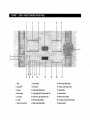
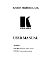
Figure 1 FRONTPANEL
8
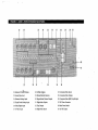
Figure 2 BACKPANEL
11
Figure 3 REMOTECONTROL
16
P/N 1960101900389
CE Marking
Unpacking
This ’product complieswith the EMC
directive (89/336/EEC)
andthe low-voltagedirective (73/23/EEC).
1. Openthe box andremovethe top layer of
foam.Youwill seetheseitems:
¯
Introducbon
®
Thankyou for your purchaseof the Krell
Audio+ VideoStandard.To obtain the best
performance from your Audio + Video
Standard surround preamp/processor,pay
careful attention to its placement,installation, andoperation. A thoroughunderstanding of thesedetails will helpinsuresatisfactory operationandlonglife for the Audio+
VideoStandardand related’ systemcompo~
nents.
THERE ARE NO USER-SERVICEABLE
® PRODUCT.
PARTSINSIDE ANYKRELL
Please contact your authorized dealer,
distributor, or KrelP,if youhaveanyquestions not addressedin this reference
manual.
® Audio + Video Standard
KRELL
1 Audio + Video Standard
1 AC power cord
1 Audio + Video remotecontrol
4 AAAbatteries
1 T-10 Torx wrench
1 packet containing an introductory
letter from DanD’Agostino,C.E.O.,
the Owner’sReference,and the
WarrantyRegistration Card
Note
If anyof theseitemsare not included,please
contactyour authorizedKrell® dealer or distributor immediately
for assistance.
Carefully removethe unit and accessories from the box. Remove
the protective plastic wrapfromthe unit.
Note
Saveall packingmaterials, ff youmustship
your Audio+ VideoStandardin the future,
repackthe unit in its original packagingto
preventtransit damage.
English Page3 of 32
Placement
WARNING
The surround preamp/processor must not
be locatedwhereit couldbe exposed
to dripping or splashin~luids.
IMPORTANT
Theventilation grids andcooling fan on the
top of the Audio + Video Standardneedto
be unobstructedat all times during operation. Do not place flammablematerial on
top of or beneath the Audio + Video
Standard.For installations inside cabinet04,
makesure the Audio ÷ Video Standardhas
adequate
air circulation. Contactyour dealer,
distributoror Krell~ for further information.
Before you install
the Audio + Video
Standard. into your system, review the
following guidelines to choosethe optimumlocation for placement. This will
help ensurea clean, trouble-free installation. For the dimensions of the Audio +
Video Standard, see Specifications on
back cover.
Page4 of 32 English
Place the Audio + Video Standardsurround
preamp/processoron a firm level surface
awayfrom dirt or moisture. A minimum
spacing of three inches must exist betweenthe
Audio + Video Standard and surrounding
components
to ensureproperventilation.
AC POWER GUIDELINES
WARNING
Do not removeor bypass the ground pin
on the end of the ACcord. This maycause
RFI (radio frequency interference) to
induced into your playback system.
TheAudio+ Video Standardhas superbregulation and doesnot require a dedicatedAC
circuit. Avoidconnectionsthroughextension
cords or multiple ACadapters.Highquality,
15 ampere,groundedACstrips are acceptable. Highquality ACline conditionersor filters maybe usedif they are grounded.
® Audio + Video Standard
KRELL
Front Panel
Description
See Figure 1 on page 8
1 Tape
A tape monitor al!~ws you to comparethe
output from your a~logtape recorderto the
original source while makinga recording.
After selecting a sourcefor recording (B1,
$1-$5), press the tape button to toggle
betweenthe tape recorder output (LEDilluminated)andthe input source(LEDnot illuminated).
2 AnalogIn
TheAnalogIn button activates the analog
input and cycles .through the six analog
audio inputs. B1is a balancedinput via XLR
connectors. $1-$5 are single-endedinputs
via RCAconnectors.
3 Digital In
TheDigital In button activates the digital
input andcyclesthroughthe six digital audio
inputs (C1, C2, T1, T2, XLR,and RF). The
main display will showRFIN whenthe RF
input for DolbyDigital (AC-3)is selected.
C1 and C2 are coaxial inputs via RCA
connectors.
TM inputs.
T1 andT2 are TosLink
XLRis an AES/EBU
connection.
RFis available via RCAor BNCconnectors. Thereis no front panelLEDfor this
digital input.
5 Composite
The composite video input button cycles
throughthe four compositevideo inputs.
6 S-Video
TheS-videoinput button cycles throughthe
four S-videoinputs.
7 VolumeControl Knob
Thevolumecontrol knobadjusts the output
level for the entire systemas well as individual levels for the centerspeaker,side speakers, rear speakers,andsubwoofers.Thevolumecontrol knobnormally adjusts the mas. ter volumeas indicatedby the LEDilluminated above the master button (19). The
changein volumeis indicated in the main
display and also on-screen.Adjustmentsto
the center speaker, side speakers, rear
speakers, and subwoofers are madeby
pressing the correspondingindividual channel volumebuttons(20) androtating the volumecontrol knobto the desired setting. The
master volume control has a numerical
rangefrom 0 to 152with 89 being the Dolby
reference. Thecenter speaker, side speakers, rear speakers, and subwoofervolume
trim havea rangeof __.12dB.
8 PowerButton
The powerbuttontoggles the Audio + Video
Standardfrom standbyto operate and also
switches the 12 VDCoutput betweenon and
off.
9 Power LED
The powerLEDilluminates whenthe. rear
panel mainpowerswitch [see Figure 2 (38)
4 Main Display
,
Themaindisplay provides status.messages on page11] is placed in the on position.
for a variety of Audio+ VideoStandardoper- During remotecontrol operation, the power
LEDwill flash, indicating the Audio+ Video
ations.
Standardis receiving remotecontrol commands.
® Audio + Video Standard
KNELL
English Page5 of 32
10-16 Audio ModeButtons
automaticmutingfeature will be active. Be
Thefive buttons (10, 13, 14, 15, and 16) sureto turn all amplifiers off whenswitching
select one of the Audio+ VideoStandard’s the mainpowerswitch on andoff.
audio modes.
10 Dolby Digital engagesDolby Digital
(AC-3) processing for use with Dolby
TheAudio + Vid~.o Standardautomatically
selects whichdi~al decodingformatto use,
Digital (AC-3) encodedsourcematerial.
basedon the input signal it receives.
The Audio + Video Standard automatically switchesto DolbyDigital (AC-3)proWhen
a silent digital signal .is present,the
cessing uponreceiving a Dolby Digital
Audio+VideoStandard will automatically
(AC-3)encoded
signal. Nouser intervenmute its output until program material
tion is requiredafter the appropriatedigiresumes and the Audio+Video Standard
tal input is selectedandconnected.
identifies the correct processingmode.This
Dolby Pro Logic engages Dolby Pro
occurs while changinglaser, DVDor comLogiccircuitry for usewith all Dolbysurpact discs, andbetweentracks on a cd.
roundprocessingencodedmaterial. This
includeslaser discs, videotapes,televiMuteprotectsyour syste ,m by preventingthe
sion broadcasts,andcompactdiscs.
Audio + Video ~Standardfrom playing back
digital datain anincorrectformat.If the Audio
11 TheDolbyDigital LEDis lit and the
+ Video Standardis going to be used as a
DolbyPro Logic LED(12) is not lit when
digital to analogconverterfor musicplaythe Audio+ Video Standard is in the
back, this muting may seem awkward
Dolby Digital (AC-3) decoding mode.
becausethe beginningof eachtrack maybe
Whenboth the DolbyDigital LEDand the
affected. Youcan changethe format autoDolbyPro Logic LEDare lit, the Audio+
sensingto eliminatethis muting,if youwish.
Video Standard is decoding a Dolby
To do so, switch the unit into standby.Press
Digital (AC-3) encodedDolby Pro Logic
the DTSbutton (13) on the front panel and
signal.
switch the Audio+VideoStandard out of
12 The Dolby Pro Logic LEDis lit and
standbyto poweron (operate). This will disthe
DolbyDigital LED(11) is not lit when
able the automatic muting feature of the
the
Audio+ Video Standard is in the
Audio+Video
Standardandwill alter the way
Dolby Pro Logic decoding, mode.When
in whichthe automaticformat sensingoperboth the DolbyDigital LEDandthe Dolby
ates. Forbestresults, selectDTSprior to lisPro Logic LEDare lit, the Audio+ Video
tening to any DTSencodedmaterial and be
Standard is decoding a Dolby Digital
careful to select the properformat for each
(AC-3).encoded
DolbyPro Logic Signal.
pieceof softWareplayedthroughthe. digital
inputs.
13 DTSengagesDTSdigital surround
processing for use with DTSencoded
To re-engagethe automaticmuting feature,
source material. The Audio + Video
switch the Audio+Video
Standardinto stand$tandard automatically switches to DTS
by and toggle the mainpowerswitch (38)
processinguponreceiving a DTSsignal.
the rear panelto the off position. When.you
Nouser interventionis requiredafter the
restart your Audio + Video Standard, the
Page6 of 32 English
® Audio + Video Standard
KRELL
appropriatedigital input is selectedand
connected.
14 MusicengagesKrell MusicSurround
circuitry for usewith stereorecordings.
TM
15 Monois for use with monophonic
recordings. This provides monauraloutput from the ~nter speaker and subwoofer(s) only.~lf the systemdoesnot
include a center speaker, the monaural
signal is split between
theleft andright
speakers.
16 Preampdisengages all surround
processingcircuitry for use with stereo
recordings. Whenfed an analog source,
the Audio+ VideoStandardfunctions as
a pure ClassAi~ high resolution, analog
preamplifier. For digita, I sources,the
Audio + Vide£ Standardemploys24-bit,
customKrelP-written, digital-to-analog
conversionsoftwarebefore being sent to
the analogpreamplifier stage.
17 Recall Button
This button savesandrecalls systemconfigurationsettings..
18 Infrared Sensor
The infrared sensor receives commands
from the Audio + Video Standard remote
control. For properremotecontrol operation,
makesure the infrared sensoris clear of any
obstructions.
19-21 VolumeControl Buttons
Thefollowing six buttons select oneof the
Audio+ VideoStandard’svolumechant~els:
19 Master VolumeButton
Whenthe LEDabovethis button is illuminated, the volumecontrol knob (7)
affects the entire systemequally. Thevol-
® Audio + Video Standard
KRELL
umeadjustmentis indicated in the main
display andalso on-screen.
20 Individual Channel
VolumeTrim
Whenthe LEDaboveany of these buttons is illuminated, the volumecontrol
knob(7) changesthe level of the selected channel. These new changes will
clear whena newinput modeis selected.
Thevolumecontrol knobreverts back to
controllingthe default level, Master,after
four seconds
of inactivity.
21 Balance Button
(Preampmodeonly)
When
the LEE)abovethis button is illuminated, the volumecontrol knob (7)
affectsthe left-to-right balance
of thesystem. Thecenter position is indicated by
CNTR
in the maindisplay. Balancemaybe
adjusted in 1 dBincrementsup to 9 dB.
Thenext adjustmentmuteseither channel, indicatedby ROFF
or LOFF
for the right
channeland left channel respectively.
Theon-screen representation for balanceis graphical:
L .........
: .........
R
Thecenter position is indicated by two
vertical dots, EachdBof adjustmentis
represented by one individual dot.
Movingthe cursor so that it coversthe L
indicates a completelymutedright channel. Conversely,positioningthe cursorso
that it coversthe R indicatesa completely muted-left channel.Thevolumecontrol
knob(7) reverts backto controlling the
default level, Master,after four seconds
of inactivity.
English Page7 of 32
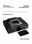
FIGURE 1
AUDIO + VIDEO STANDARD FRONT PANEL
2
3
4
6
5
9
11
1 Tape
2 Analog~’~
3 DigitalIn
4 MainDisplay
5 Composite
10 13
15
17
12
14
16 ..
18
19
8 PowerButton
9 Powe~LED
10 DolbyAudioModeButton
11 DolbyDigital (AC-3)AudioMode
LED
12 DolbyPro Logic AudioModeLED
6 S-Video
13 DTSAudio ModeButton
7 VolumeControl Knob
14 MusicAudioModeButton
2O
21
15 MonoAudioModeButton
Audio ModeButton
16 Preamp
17 RecallButton
18 InfraredSensor
19 MasterVolumeButton
20 Individual Channel
Volume
Buttons
21 BalanceButton
Back Panel
Description
Connections are via RCAor BNCcoaxial
digital cable.
See Figure 2 on page 11
27 S-Video Inputs
The Audio + Video Standard is equipped
with four S-videoinputs (labeled1-4).
22 Balanced Channel Outputs
The Audio + Vid~p Standard is equipped
with nine channel~utputs. All nine channels
are equippedwith balancedoutputs via XLR
connectorsas well as single-endedconnectors (30). Thenine channeloutputs are for
thecenter,left, right, left andright side, left
and right rear, and two subwooferoutputs
(labeled Sub1,Sub2).
TheXLRpin configurationsare as follows:
Pin 1" Shield(g~round)
Pin °,)
2: Non-inverting
(0,
Pin °3:) InvertiNg(180
23 AnalogTape Input
The Audio + Video Standard is equipped
with onesingle-endedtape input.
24 BalancedAnalogInputs
The Audio + Video Standard is equipped
with one balanced input (labeled B1) via
XLRconnectors.
28 S-Video Outputs
The Audio + Video Standard is equipped
with three S-videooutputs. ThemainS-video
output (labeled on screen) includes onscreen graphics. For dubbingpurposes,the
second and third S-video outputs do not
include on-screengraphics.
29 Infrared RemoteSensors
The Audio + Video Standard is equipped
with an additional infrared sensoranda male
basebandRC-5 remote input for custom
installations.
30 Single-EndedChannel Outputs
The Audio + Video Standard is equipped
with nine channeloutputs. All nine channels
are equippedwith single-endedoutputs via
RCAconnectors as well as balanced connectors (22). Thenine channeloutputs are
for the center,left, right, left andright side,
left and right rear, and two subwooferoutputs (labeled Sub1,Sub2).
TheXLRpin configurationsare as follows:
Pin 1: Shield (ground)
Pin °)
2: Non-inverting(0
Pin °3:) Inverting (180
25 Single-EndedAnalogInputs
The Audio + Video Standard is equipped
with five single-ended
in puts(labeledS’1-$5)
via RCAconnectors.
26 RF Inputs
TheAudio+ VideoStandardis equippedwith
an RFinput for use with the Dolby Digital
(AC-3) RFoutput of a laser disc player.
® Audio + Video Standard
KRELL
31 Digital AudioOutputs
The Audio + Video Standard is equipped
with twodigital audiooutputsin the following
formats:
Onecoaxial via RCAconnector
TM
OneTosLink
32 Tape Outputs
The Audio + Video Standard is equipped
with three analogtape outputs. Twoare for
use with video sources (labeled VCR1,
VCR2),and.thethird is for use with an audio
tape deck(labeled tape).
English Page9 of 32
33 Digital AudioInputs
The Audio + Video Standard is equipped
with five digital audioinputs in the following
formats:
Twocoaxial via RCAconnectors
TM
TwoTosLink
OneAES/EBUvixen XLRconnector
34 CompositeVideo Inputs
The Audio + Video Standard is equipped
with four RCAcomposite video inputs
(labeled1-4).
35 CompositeVideo Outputs
The Audio + Video Standard is equipped
with three RCAcomposite video outputs.
The main compositevideo output (labeled
on screen) includes on-screen;graphics.For
dubbing purposes, ~the second and third
compositevideo outputs do not include onscreengraphics.
36 CompositeVideo (BNC) Input/Output
The Audio + Video Standard includes one
composite video input and one composite
video output via BNCconnectors. These
Page10 of 32 English
ports are electrically identical to the RCA
compositevideo inputs (34) and, outputs
(35).
Note
You maysimultaneously use both RCAand
BNC
outputs, but only oneof the inputs.
37 IEC PowerConnector
The Audio + Video Standard is equipped
with a standard female IEC powerconnector.
38 Main PowerSwitch
Togglesthe Audio+ VideoStandardbetween
off andstandby.
39 12 VDCOutput
Activatedby the front panelpowerbutton(8),
the 12 VDCoutput sends a 12-volt power
on/off signal to other Krell ® components,
as
well as to other devicesthat incorporate a
12-volt poweron/off trigger input. Thisallows
for remoteturning on/off of other components whenthe Audio + Video Standardis
doweredon.
® Audio + Video Standard
KRELL
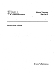
FIGURE 2 AUDIO +VIDEO STANDARD BACK PANEL
22
23
30
22
22 Balanced Ch~l Outputs
23 AnalogTape~nput
24 BalancedAnalogInputs
25 Single-Ended
AnalogInputs
26 DolbyDigital Inputs
27 S-VideoInputs
32
24
31
25
26
33
S-Vid
oOuts
29 In~raredRemote
Sensors
ChannelOutputs
30 Single-Ended
31 Digital AudioOutputs
32 TapeOutputs
33 Digital AudioInputs
27
28
34
35
36
39 29
34 Composite
VideoInputs
VideoOutputs
35 Composite
36 Cdmposite
Video(BNC)Input/Output
37 IECPowerConnector
38 MainPowerSwitch
39 12 VDCOutput
Connectingthe
Audio + Video Standard
to Your System
WARNING
Whenmaking conn~ions to thi.s component or any other, makesure the power
amplifier is off andthe preamplifieris in the
mute or stand-by mode. Make sure all
cable terminationsare of the highest quality, free from frayed ends, shorts, or cold
solderjoints.
For analog audio sources, connect the
left andright outputsof your sourcecomponentsto the inputs on ,the Audio +
Video Standard. The Addio + Video
Standardis equippedwith six singleended analog audio inputs ($1-$5 and
tape) via RCAconnectors and one balancedanalog audio input (B1) via
XLRconnector.
Connectthe video outputs of your video
sourcesto the video inputs on the Audio
+ Video Standard.
The Audio + Video Standard is equipped
with four S-videoinputs andfour composite
video inputs. S-video cables transmit the
color and luminance componentsof the
video signal separately. This separationis
performed by the combfilter within the
sourceunit. If the sourceunit’s comb
filter is
superior to the onewithin the videomonitor,
S-video connections should be used.
Otherwise, a composite video connection
should be used.
Notes
S-video cables should not be used for
lengths greater than 20 feet, for optimum
performance.
TheAudio + Video Standarddoes not convert video signal formats, Le., an S-video
input signal is output as an S-videosignal
Thesamecondition holds true for a composite video signal
2. For digital audio sources, connectthe
digital audio output of your sourcecom- The Audio + Video Standard is equipped
ponents
to the digital inputsonthe Audio+ with three S-video outputs and three comVideo Standard. The Audio + Video
posite video outputs. ThemainS-videooutStandardis equippedwith five digital
put (28) and compositevideo output (35)
inputs: two coaxial inputs via RCAcon- include on-screen graphics. Thecomposite
nectors, two TosLinkTM optical connec- video 1 output also has a parallel BNCcontions, and one AES/EBUvia an XLR nector. For dubbing purposes, the second
connector.For DolbyDigital (AC-3) surand third video outputs do not include onroundprocessing,connectthe RFoutput screengraphics. Theseoutputs maybe conof a laser disc player to oneof the RF nected to the video inputs of your video
inputs.
recordersor to:additional videomonitors.
Note
For sourceunits that are equippedwith both
digital andanalogaudiooutputs,higher performancewill generally result whenconnecting sourceunits to the Audio+ VideoStandard
usinga digital audiooutput.
Page12 of 32 English
Connectthe outputs of the Audio+ Video
Standardto the input(s) of your power
amplifier(s).
® Audio + Video Standard
KRELL
Connectthe outputs of the Audio+ Video
Standardto the input(s) of your power
amplifier(s).
RemoteControl
Description
See Figure 3 on page 16
The Audio + Video Standard has balanced
outputs via XLRconnectors and singleended outputs ~,, RCAconnectors. Both
outputs are act~e at all times, allowing
simultaneousconnectionto separateamplifiers. Only one of these output formats
shouldbe connected
to a single amplifier.
40 AnalogAudio Input Buttons
These buttons select the analog audio
source. B1 is a balancedinput via XLRcon-.
nectors while $1-$5are single endedinputs
via RCAconnectors.Thetape button allows
accessto an analogtape recorder.
Note
41 Digital AudioInput Buttons
Whenconnecting inputs or outputs to the These buttons select the digital audio
Audio + Video Standard, remember
that the source. C1 and C2 are coaxial inputs via
balancedconnections will have 6 dB more TM
RCAconnectors, T1 and T2 are TosLink
gain than the single-endedconnections. If
inputs, XLRis an AES/EBU
connection, and
level matchingbecomesdifficult in your RFis available via RCAor BNCconnectors.
installation, keepthis spe~’ficationin mind.
42 Processing ModeButtons
5. Plug the ACcord into the receptacle on Thefollowing six buttons select oneof the
the back of the Audio+ VideoStandard. Audio + Video Standard’s processing
Plug the remainingend into the ACwall
modes.FCN,the function button, is reserved
receptacle. Toggle the main power for future use.
switch (38) to the up position. Thered
powerLED(9) will illuminate, and the The Audio + Video Standardautomatically
maindisplay (4) will showAC-3for three selects whichdigital decodingformatto use,
basedon the input signal it receives.
seconds.The Audio + Video Standardis
nowreadyfor operation.
When
a silent digital signal is present, the
Presseither the front panelpowerbutton Audio +VideoStandardwill automatically
(8) or the remotecontrol powerbutton mute its output until program material
[see Figure 3 (44) on page15]. Theword resumes and the Audio +Video Standard
WAITwill appearin the maindisplay and identifies the correct processingmode.This
the initializing message
will appearon- occurs while changinglaser, DVDor comscreen. To configure the Audio + Video pact discs, andbetweentracks on a cd.
Standard for operation, see System
Muteprotects your systemby preventingthe
Configurationon page18.
Audio + Video Standardfrom playing back
digital data in an incorrect format. If the
Audio+ VideoStandardis going to be used
as-a digital to analogconverter for music
playback, this muting mayseemawkward
becausethe beginningof eachtrack maybe
affected. Youcan changethe format auto® Audio + Video Standard
KRELL
English Page13 of 32
sensingto eliminatethis muting,if youwish.
Todo so, switch the unit into standby.Press
the DTSbutton (13) on the front panel and
switch the Audio+Video Standard out of
standbyto poweron (operate). This will disable the automatic muting feature of the
Audio+Video
Stan,~ardandwill alter the way
in whichthe automaticformat,sensingoperates. For bestresults, select DTSprior to listening to any DTSencodedmaterial and be
careful to select the properformatfor each
piece of softwareplayedthroughthe digital
inputs.
To re-engagethe automaticmutingfeature,
switch the Audio+Video
Standardinto standby andtoggle the mainpowerswitch (38)
the rear panel to the off position. When
you
restart your Audio + Video Standard, the
automaticmutin~feature will be active. Be
sure to turn all amplifiers off whenswitching
the mainpowerswitch on andoff.
appropriatedigital input is selectedand
connected.
T"
Music engagesKrell Music Surround
circuitry for usewith stereorecordings.
Monois for use with monophonic
recordings. This provides monauraloutput from the center speaker and subwoofer(s) only. If the systemdoesnot
include a center speaker, the monaural
signal is split between
the left andright
speakers.
Prearnpdisengagesall surround processing circuitry for use with stereo
recordings. Whenfed an analog source,
the Audio+ VideoStandardfunctions as
a pure ClassA, high resolution, analog
preamplifier. For digital sources, the
Audio+ VideoStandardemploys24-bit,
customKrell®-written, digital-to-analog
conversionsoftwarebefore being sent to
the analogpreamplifier stage.
Dolby Digital engagesDolby Digital
(AC-3) processing for use with Dolby
Digital (AC-3) encodedsourcematerial.
The Audio + Video’ Standardautomatically switchesto DolbyDigital (AC-3)processing uponreceiving a DolbyDigital
(AC-3)encoded
signal. Nouser intervention is requiredafter the appropriatedigital input is selectedandconnected.
43 Levels Buttons
These buttons select one of the Audio +
Video Standard’s volumechannels.
Dolby Pro Logic engages Dolby Pro
Logiccircuitry for usewith all Dolbysurroundprocessingencodedmaterial. This
includeslaser discs, videotapes,television broadcasts,andcompactdiscs.
Muteinterrupts any audio signal to
source equipment.
Masterselects all channelsfor systemwidevolumecontrol.
Balance (PreampModeOnly) adjusts
the left-to-right balanceof the system.
44 PowerButton
Thepowerbutton toggles the Audio+ Video
Standardfrom standbyto operate.
DTSengagesDTSdigital surround processing for use with DTS encoded
source material. The Audio + Video 45 Vol Down/VolUp.Buttons
Standardautomatically switches to DTS The-voldownandvol up buttons control the
volumefor either the entire systemor for an
processinguponreceiving a DTSsignal.
Nouser interventionis requiredafter the
Page14 of 32 English
® Audio + Video Standard
KRELL
individual channel,a~: selectedby the levels
buttons(4,3).
46 Amplifier Buttons
®
Thepowerandmeterbuttons operateKrell
amplifiers.
47 System Button~
Thesebuttons select a preassigned video
input. Oncea videoin put is assigned,it may
then be linked to a specific audioinput and
surroundmode.For details on this assigning
and linking procedure, see Direct Access
RemoteControl SystemProgrammingon
page24.
49 Enter Button
This button inputs on-screen menuselections (functions only in the menumode).
50 Scroll Buttons
Thesefour buttons scroll on-screen menu
options, and also are usedfor volumecontrol.
51 MenuButton
This button accesses, the on-screen menu
functions.
52 Previous Button
This button escapesor ends certain
screen menuoperations.
on-
48 Video Buttons
Thesebuttons select the video source.CV1CV4are compositevideo inj~uts, and SV1SV4are S-videoin.puts.
® Audio .- Video Standard
KRELL
English Page15 of 32
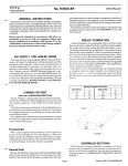
FIGURE 3 AUDIO + VIDEO STANDARD REMOTE CONTROL
46
49
4O
41
50
42
52
44
43
40 AnalogAudioinput Buttons
41 Digital AudioInputButtons
42 ProcessingModeButtons
43 LevelsButtons
45
47
48
44 PowerButton
45 Vol Down/Vol UpButtons
48 VideoButtons
49 EnterButton
46 AmplifierButtons
50 Scroll Buttons
51 MenuButton
47 SystemButtons
52 PreviousButton
Page16 of 32 English
® Audio + Video Standard
KRELL
BATrERY INSTALLATION
AND REMOVAL
Note
Batteries should be replacedwhenfunctions
fromthe remotecontrol become
intermittent.
The Audio + Video Standard remote uses
four AAAsize 1.~olt .batterie
s
the backplateto exposethe bat1. Remove
teries.
® Audio + Video Standard
KRELL
2. Remove
the old batteries.
Install the newbatteries, following the
battery position diagramon the plastic
battery receptacle.
4. Re-install the backplate.
5. Checkto makesure the remotecontrol is
functioningproperly.
English Page17 of 32
SystemConfiguration
STEP1
CONFIGURE SPEAKERS
Theremotecontrol is the maininput device
for the Audio+ VideoStandard.All initial
setup and subsequentsystemconfiguration
adjustmentsm~.~t be madevia the remote
control. Theremotecontrol, also includes
functionsfor KrelPpoweramplifiers.
To configure the Audio+ VideoStandardfor
the specific types of speakersusedin the
system, highlight CONFIGURE
SPEAKERS
and
pressthe enter button (49). Thespeakersys-.
temsetup menuwill appear:
For maximumperformance, the Audio +
Video Standardneedsto be configured for
systemelements, their capabilities, and
positionswithinthe listening room.Thisinformation is entered into the Audio + Video
Standard via on-screen menus. These
menusare structured to guide you through
the setup process.
KRELL A+V STANDARD
- SPEAKERSYSTEMSETUP
TYPE
PRSNT
(X)
(X)
(X)
(X)
FRNT: FULL-RANGE
CNTR: FULL-RANGE
SIDE:
FULL’RANGE
REAR: FULL’RANGE
SUBS: DUAL MONO
OK
ACCESSING THE MAIN MENU
To begin the systemconfiguration procedure, connectthe on-screenvideo output of
the Audio + Video Standard(28 or 35)
your videomonitor. Set the video monitorto
this input, Press the remotecontrol menu
button (51)and the’main menuscreen will
appear:
KRELL A+V STANDARD
- MAIN MENUCONFIGURE SPEAKERS
LISTENING ROOMSETUP
CALIBRATE VOLUME
CONFIGUREINPUTS
CONFIGURE MUSIC MODE
OPERATION
The Audio+ Video Standard is nowready for
configuration.
Page18 of 32 English
The FRNT (front), CNTR(center), SIDE, REAR,
,and SUBS(subwoofers) indicate possible
speakerlocations. The(x) indicates speakers that are currently presentin the system
(the front speakers cannot be defeated,
hencethe absenceof parentheses).
FortheFRNT, CNTR, SIDE, andREARselections,
the on-screenmenu
offers the optionsof full
range or bass limited. The proper choice
depends
uponthe low frequencycapabilities
of eachspeaker.For the SUBS
selection, the
on-screenmenuoffers the options of mono,
dual mono,stereo, or front andrear.
Thedefault settings are displayedfor each
speaker.If your systemcorrespondsto the
default settings, highlight OKandpressEnter.
Youwill be returned to the mainmenu,and
you mayproceedto Step 2, listening room
setup, if youneedto modifythe speakersettirfgs, proceed
as follows:
® Audio + Video Standard
KRELL
Modifyingspeakersettings
Highlight the appropriate( ) that represents
To disablea speaker,highlight the appropri- the subwooferconfiguration in your system
and press Enter. The (x) will nowappear
ate (×) andpressEnter.
next to the newsubwoofersetting. Highlight
To enablea speaker,highlight the appropri- OKand press Enter. Youwill be returned to
the speaker systemsetup menu.Highlight
ate ( ) andpressEnter.
OKand press Enter again to return to the
To changethe ~ttings for the FRNT,CNTR, main menu.
SIDE, or REAR, highlight the appropriate
phrase and press Enter. Thespeakersetup STEP 2
menuwill appear:
LISTENING ROOM SETUP
KRELLA+V STANDARD
-SPEAKERSETUPF THESESPEAKERS
ARE NOT
DESIGNED TO REPRODUCE
DEEPBASS, CHECKTHE BOX
BELOW:
(
BASSLIMITED SPKR
OK
If the selected speakerdoes not have the
capability to reproduce
low frequencies,highlight the (), press Enter, highlight OKand
pressEnteragain.Youwill be returnedto the
speaker systemsetup menu.Theon-screen
phrasefor the selectedspeakerwill nowread
To tell the Audio + Video Standard where
eachspeakeris locatedwithin the listening
room, highlight LISTENING
ROOM
SETUP
and
press Enter. Thelistening roomsetup menu
will appear:
KRELL A+V STANDARD
- LISTENINGROOM
SETUPLEFT
OFT
CENTER
OFT
RIGHT
OFT
L SIDE
OFT
SUB1
OFT
R SIDE
OFT
L REAR
OFT
SUB2
OFT
R REAR
OFT
The0 FmunderLEFTwill be highlighted. Press
Enterandthe 0 will start blinking. Usethe up
scroll
button (50) to increasethe number
To changethe settings for the subwoofers,
highlight SUBS
andpressEnter. Theconfigure the correct distancein feet fromthe mainlistening position to the left speaker. Press
subwoofersmenuwill appear:
Enter again andthe numberwill stop blinking. Usethe right scroll buttonto highlightthe
KRELLA-I-V STANDARD
- CONFIGURE
SUBWOOFERS
0 FTunderCENTER.
PressEnterandthe o will
start blinking. Usingthe sameprocedureas
SELECTA CONFIGURATION:
before, input the correctdistancefor the cenSINGLE MONOSUB
(
ter speaker. Dothe samefor the remaining
MONO
SUBS
(x) DUAL
speakersin the system.After all the dis(
STEREOSUBS
tances are set, press the Previous button
FRONT
&
REAR
SUBS
(
(52) to return to the mainmenu.
BASSLIMITED.
OK
® Audio: + VideoStandard
KRELL
EnglishPage19 of 32
Note
Auto Noise Sequence
Any speakernot Configuredin the speaker
Set the SPLmeter to C weighting and slow
system setup menuwill display N/A (not
response.After initializing, the LEFT
channel
available)for the distancespecification.
dBsetting will be blinking, andbanded
white
noisewill be heardthroughthe left speaker.
STEP3
This noise will continuefor two secondsand
CALIBRATE THE VOLUME
then moveclockwise to the next speakerin
the system.Usingthe up or downscroll but~
Note
.~
~
A soundpressure/eve/(SPL) meter is nec- tons, adjust eachspeaker’ssetting until the
SPL.meter reads 75dR. This adjustment
essaryfor this procedure
....
mustbe made
while the individual channelis
blinking.
Repeat
for all remainingspeakers.
To adjust individual speakeroutputsfor propWhen
all
the
speakers
are set, press
er balancethroughoutthe system,highlight
Previoustwice to return to the mainmenu.
CALIBRATE
VOLUME
and press Enter. Thecalibrate volumemenuwill appear:
Manual Noise Sequence
KNELL A+V STANDARD
Set the SPLmeter to C weighting and slow
response.After initializing, the LEFTchannel
SELECTTHE CHANNELCAI~IBRATION METHOD
dBsetting will be highlighted. PressEnter
andwhite noise will be heardfrom the left
AUTO NOISE SEQUENCE
speakeras the o starts blinking. Usingthe up
MANUAL NOISE SEQUENCE
or downscroll buttons,adjustthe setting until
PROGRAMMATERIAL
the SPLmeter reads 75dR.Press Enter and
use the right scroll button to highlight the
Highlightoneof the choicesandpressEnter.If
channel dB setting. Using the same
you chooseAUTO
NOISESEQUENCE
or MANUALCENTER
channel
NOISE
SEQUENCE,
the message
INITIALIZING... procedureas before, set the CENTER
will blink while the Audio+ VideoStandard volumeto 75 dB. Repeatfor all remaining
loadsits internal noisegenerator.Thefollow- speakers. Whenall the speakersare set,
press Previoustwice to return to the main
ing screenwill thenappear:
menu.
- CALIBRATEVOLUME-
KNELL A+V STANDARD
- CALIBRATEVOLUMELEFT
CENTER
0 DB
0 DB
RIGHT
0 DB
SUB 1
R SIDE
0 DB
0 DB
SUB 2
R REAR
0 DB
0 DB
L SIDE
0 DB
L REAR
0 DB
Page20 of 32 -English
Notes
Whenusing an external noise generator for
volumeconfiguration,soundwill outputsimultaneously from all speakersin the system.
Adjustmentscan be madeto any speakerin
the systehn with the results immediately
apparentto the balanceof the wholesystem.
Anyspeakernot configured in the speaker
system setup menuwill display N/’A (Not
available)for the dBspecification.
® Audio + Video Standard
KNELL
The subwoofer designation will change
dependingon the configuration entered in
the speakersystemsetup menu.For a mono
setup, the subwoofersare designatedSUB1
andSUB2. For a left andright stereo setup,
the subwoofers are designated sue L and
sue R. For a fro~ and rear setup, the subwoofersare designatedSUBF andSUBR.
KRELLA+V STANDARD
- INPUTNAME
WHICHINPUT NAME
DO YOU WANTTO CHANGE?
S-VIDEOINPUTS
SVl SV2 SV3 SV4
COMPOSITE
VIDEOINPUTS
CVl CV2 CV3 CV4
STEP 4
CONFIGURE THE INPUTS
Highlight any of the S-video or composite
video inputs and press Enter. A secondary
Toconfigureinputs, highlight CONFIGURE
INPUTS screenwill appear(S-video1 is shownas an
and press Enter. Theconfigure inputs menu example):
will appear:
KRELLA+V STANDARD
- INPUTNAME-
KRELLA+V STANDARD
- CONFIGURE
INPUTSE~ T INPUTNAMES
SET ANALOG
INPUT LEVEL
SETVIDEOINPUTLINKS
PAL VIDEOSETUP
Highlight EDITINPUTNAMES
andpress Enter.
Theinput nametype menuwill appear:
KRELL A+V STANDARD
- INPUTNAMEWHATTYPEOF INPUT NAME
DO YOUWANTTO CHANGE?
VIDEO
ANALOG
DIGITAL
Highlight VIDEO
and press Enter. Theinput
namemenuwill appear:
® Audio+ VideoStandard
KRELL
INPUT:S-VIDEO1
NAME:S-VIDEO1
e-- & --> TOMOVE
CURSOR
1" & $ TOCHANGE
TEXT
PRESSENTERWHENDONE
Thefirst letter of the input name
will blink and
can be changedusing the up or downscroll
buttons.Movethe blinking cursorto the letter
youwantto change
andadjust to the letter of
your choice. Thenamefield is limited to a
maximum
of 12 characters. Available charactersare:
A-Z
1-9
’
< >
and a blank space. Whencompleted, press
Enterto finish the editing andreturn to the
input namemenu.Chooseanother input to
adjust or pressPreviousto return to the input
namemenu,Chooseanother input nameto
modify or press Previousto return to the
configure inputs menu.
EnglishPage21 of 32
Special AnalogSources
Theanaloginput sensitivity of the Audio+
VideoStandard
is set for the standard2 Volts
that DolbyLaboratoriesmandates
for proper
Dolby Pro Logic processing. For analog
sources (componentsconnected to $1-$5
and tape) that do n~correspon.dto a standard 2 Volt output ~pecificationl, it maybe
necessary
to adjust individual input levels on
the Audio+ VideoStandard.
PressMenuto exit the menusystem,select
the desired analoginput andreturn to the
configure inputs menu.
Highlight SETANALOG
INPUTLEVEL
and press
Enter. Theset input .levels menu
will appear:
- SETIt~PUT LEVELSINPUT: B1
L
R
- OVERLOAD
-
scroll button,raise the level dBsetting until
OVERLOAD
starts blinking andthen reducethe
setting just belowthis threshold.
When
the input level has beenproperly set,
highlight OKandpress Enterto return to the
configure inputs menu.To adjust additional
inputs, exit the menusystemby pressing
Menu,select the desiredinput, return to the
set input levels menuwithin the configure
inputs menu,andfollow the sameprocedure
as above.
Linkinga VideoInput
to an AudioInput
Eachvideo input (S-video and composite
video)maybe linked to a specific audioinput
and surround mode. Therefore, when a
videoinput is configuredandthen selected,
its matchingaudio input and surroundmode
will also engage.Highlight sETVIDEO
INPUT
LINKSwithin the configure inputs menuand
press Enter. Theset video input links menu
will appear:
LEVEL: 0 DB
OK
KRELL A+V STANDARD
- SET VIDEOINPUTLINKS -
Beginplaybackof the selectedsourceusing
programmaterial with loud passages.Press
Enter. TheLEVEL
dBspecification will begin
blinking.
WHICHVIDEO INPUT LINKS
If the sourceunit’s outputis greaterthanthe
standard2 Volts, OVERLOAD
will blink indicating an input signal greater than standard.
Usingthe downscroll button, lowerthe level
db setting until OVERLOAD
stopsblinking. "
COMPOSITEVIDEO INPUTS
CV1 CV2 CV3 CV4
WOULDYOU LIKE TO SET?
S-VIDEO INPUTS
SVl SV2 SV3 SV4
Highlight any of the S-video or composite
video inputs and press Enter. A secondary
screenwill appear:
Conversely,
if the sourceunit’s output.is less
thanthe standard2 Volts, it will be necessary
to raise the input level sensitivity for proper
Doiby surround processing. Using the up
Page22 of 32 - English
® Audio + Video Standard
KNELL
KRELL A+V STANDARD
- LINK INPUTWHICHINPUT LINK
DO YOU WANT TO CHANGE?
Note
If a videoinput is linked to botha digital and
an analoginput, the Audio+ VideoStandard
will select the digital input as the mainaudio
sourcewhenever
the video input is selected.
ANALOG
Whencompleted, highlight OKand press
Enterto return to the link input menu.At this
point you maychooseto changethe linked
Highlightthe audioinput style, either ANALOGoperating mode.To changea linked operator DIGITAL,and press Enterl If ANALOG
is
ing mode,highlight MODE
and press Enter.
selected, an additional screenappears:
The operating modelink input screen will
appear:
%~,DIGITAL
~ MODE
KRELL A+V STANDARD
- LINK INPUTSELECT AN ANALOGINPUT
TO ~INK TO SVI:
( )B1( )Sl
(
( )s4
OK
Highlight the appropriate analoginput and
press Enter. Whencompleted,highlight OK
andpress Enter to return to the link input
menu.At this point you maychoosea digital
input or operating modeto link with the
selectedvideoinput.
KRELL A+V STANDARD
- LINK INPUTo
SELECTA MODETO LINK
TO SVl :
(X) MOVIE
( ) MUSIC
( ) PREAMP
OK
Notes
If a videoinput is linkedto a digital inputand
MOVIE
is in the linked mode,the Audio+ Video
Standardwill select the appropriatedigital
surroundprocessingmode,either Dolby Pro
Toselecta linkeddigital input, highlightDIGITAL Logic, DolbyDigital or DTS,dependingupon
andpressEnter. Thedigital link input screen whichsignal is present.
will appear:
If a video input is linked to an analoginput
and MOVIE
is the linked mode,the Audio +
KRELL A+V STANDARD
Video
Standard
will select DolbyPro Logic
- LINK INPUTas the surroundprocessing mode.
SELECTA DIGITAL INPUT
TO LINK TO SV1:
( ).COAX
( ) OPTIC
( ) COAX
( ) OPTIC
( ) AES-EBU
( )
OK
® Audio -+ Video Standard
KRELL
If a videoir~put is linkedto anyanalogor digital input and MUSIC
or PREAMP
is the linked
mode, the Audio + Video Standard will
proce,ss the linked audiosignal in the selected mode,unlessthe input is a digital signal
containingeither DolbyDigital or DTSdata. In
English Page23 of 32
this case, the appropriate processingmode
will beselected.
Highlight the desired modeandpress Enter.
Whencompleted, highlight OKand press
Enterto return to the link input menu.Select
anothervideoinput to I!#~k or pressPrevious
to return to the configu~inputs menu.
Direct AccessRemoteControl
System Programming
Systemprogramming
functions allow you to
simplify the use of your Audio + Video
Standard by namingthree sets of linked
inputs, System
1, 2, and3 (47). Otherlinks
may be created in the Audio + Video
Standard,but primary, links maybe set up
and rememberedmore easily with the
Systemfunction. For example:
Systembutton 1 A laser disc connected to the RF input and a video
input, set for MOVIE
MODE.
Systembutton 2 A DVDplayer connected to the C1 input and a video
input, set for MOVIE
MODE,
Systembutton 3 A CD player connected to an analog input and an
unused video input, set for preamp
mode.
To use the system programmingfunction,
the basic input links needto be created.
For details, see Linking a Video Input to
an Audio Input on page 22. To assign
input links to System1, 2, or 3, follow the
instructions below.
Pushand release one of the three systeaq buttons.
Decide which video input you want to
assign to the systembutton. Pushand
Page24 of 32 English
hold the appropriate video button down
for approximatelyfive seconds.Notethat
the red LEDin the upperleft cornerof the
remotecontrol will blink. When
the blinking stops andthe light stays lit for one
secondthe systemis linked to the video
input you selected.
Link the video inputs to a specific audio
input and surround mode.
Selecting the BroadcastStandard
TheAudio+ VideoStandardwill operate in
both the NTSCand PALbroadcasting standards. For countries that only use the NTSC
broadcastingstandard, all S-videoandcomposite videoinputs are alreadyset for proper NTSCoperation. For countries that use
both the NTSCand PALbroadcasting systems, the SV-3, SV-4, CV-3, and CV-4 are
factory set to the PALoperating system.To
adjust the broadcastoperating settings for
any of the video inputs, enter the PALvideo
setup menulocated within the configure
inputs menu:
KRELL A+V STANDARD
- PAL VIDEOSETUPSELECTTHE INPUTS THAT
HAVE PAL VIDEO SOURCES:
( )sv-1()cv-1
( ) sv-2( ) cv-2
( ) sv-3( ) cv-3
( ) sv-4( ) cv-4
OK
Highlight the inputs that have PALvideo
sources attached to themand press Enter
so that an,(x) appearsnext to the desired
input. To defeat a PALvideo source, press
Enter so the x disappears.Whencompleted,
highlight OKandpressEnter to return to the
® Audio + Video Standard
KRELL
configureinputs menu.PressPreviousto
return to the mainmenu.
KRELL A+V STANDARD
- CONFIGUREMUSIC MODESELECT THE SPEAKERSTO
STEP 5
CONFIGURE THE MUSIC MODE
It is oftendesiral~eto havethe settingsfor
music
listening dl~erentfrommovielistening.
Highlight CONFIGURE MUSIC MODEand press
Enter. Theconfiguremusicmode
screenwill
appear:
KRELL A+V STANDARD
- CONFIGUREMUSIC MODETHE A+V STANDARDWILL
BE SET TO MUSIC MODE.
OK TO CONTINUE?
YES
NO
HighlightYESandpressEnter. Theconfigure
musicmode
screenwill appear:
KRELL A-I-V STANDARD
- CALIBRATEMUSIC MODEADJUST OUTPUTLEVELS
CONFIGURE SPEAKERS
- NOTETHESE ADJUSTMENTSARE
FOR MUSIC MODEONLY!
Highlight CONFIGURE SPEAKERS and press
Enter. A second
screenwill appear:
® Audio+ Video Standard
KRELL
BE ACTIVE IN MUSIC MODE.
( ) SIDE SPEAKERS
( ) REAR
SPEAKERS
OK
Highlightthe speakersto be active in the
musicmodeand press Enter. Whencompleted,highlightOKandpressEnterto return
to the main configure musicmodemenu.
Beforeproceeding,highlight ADJUST
OUTPUT
LEVELS
andpressEnter. Theconfiguremusic
modemenuwill appear:
KRELL A+V STANDARD
- CALIBRATEMUSICMODELEFT
RIGHT
0 DB
0 DB
L SIDE
0 DB
L REAR
0 DB
SUB 1
R SIDE
0 DB
0 DB
SUB 2
0 DB
R REAR
0 DB
Thedisplayedspeakerarray will duplicate
the system
profile inputinto the speaker
systemsetupmenu.The center speakeris not
displayedbecause
it is not active in the
musicmode.The Audio+ VideoStandardis
nowcalibrated and setup for all movie
modesand musicmode,Select the appropriate audioandvideoinput andsimplyturn
upthe volume.
English Page25 of 32
Operation
VOLUME
Theoperationmenu
offers optionsfor a variety of Audio+ Video Standarduser operations andfeatures. Fromthe mainmenu,highlight OPERATION
andpress Enter. This operation menuwill appe~:
KRELL A-IV STANDARD
- OPERATION
-
The default on-screen volume display is
numerical.TheAudio+ VideoStandard’svolumecontrol ranges from 0 to 152 with 89
representing the Dolbyreference level. To
changethe mainvolumeto a bar graph display, highlight MAINVOLUME
DISPLAY
andpress
Enter. The main volumedisplay menuwill
appear:
BACKGROUNDCOLOR
MAIN VOLUMEDISPLAY
KRELL A+V STANDARD
- MAIN VOLUMEDISPLAY -
ON-SCREENDELAY TIME
HOWWOULDYOU LIKE THE
MAIN VOLUMEDISPLAYED?
INPUT LINK PROPERTIES
REMOTE CONTROL SENSOR
FULL SURROUNDSETUP
ANTI-CLIP CONTROL
(X) BARGRAPH
DISPLAY
( ) NUMERICDISPLAY
OK
BACKGROUNI~~ COLOR
Highlight BACKGROUND
COLOR
and press
Enter. The background color menuwill
appear:
KRELL A+V STANDARD
- BACKGROUND
COLOR-
MENU
BACKGROUND
COLOR:
(X)BLACK
( ) BLUE
( ) GREEN
( ) RED
OK
Thedefaultbackground
color is black. If blue,
green, or red is preferred, highlight the
appropriate ( ) and press Enter. Thebackgroundcolor will immediatelychangeto the
.newsetting. When
youare finished, highlight
(~KandpressEnterto return to the operation
menu.
Page26 of 32 -English
Highlight the ( ) beside BARGRAPH
DISPLAY
andpress Enter. Theon screendisplay will
nowshowthe current volumesetting relative
to maximum
volume. Total volumeis represented by sixteen dots. As volumeincreases, squaresreplacethe dots. At Dolbyreference level 89, the volumecontrol pauses
and displays REFon screen. Whenfinished,
highlight OKandpressEnterto return to the
operation menu.
ON-SCREEN DELAY TIME
On-screeninformation remainsvisible for
three seconds. The on-screen delay time
has a range from one to five seconds. To
adjust, highl!ght ON-SCREEN
DELAY
TIMEand
press Enter. Theon-screendelay time menu
will appear:
® Audio + Video Standard
KRELL
KRELL A+V STANDARD
- ON-SCREEN
DELAYHOWLONGWOULD
YOU LIKE
THETEXT TO REMAINON
THE SCREENAFTERVOLUME
ADJUSTMENT
OR CHANGING
INPUT~ANDMODES?
displayed on-screenwhenevera video input
is changed.
REMOTE CONTROL SENSOR
TheAudio+ VideoStandardreceivesinfrared
remotecommands
at the front panel infrared
sensor(18). Additionally, the Audio+ Video
3 SECONDS
Standardfeatures a duplicate remotesensor
anda malebaselJandinfrared connector(29)
PressEnterandthe 3 will beginblinking. Use on the rear panel. Theserear panelinfrared
the up or downscroll buttons to increaseor components
maybe usedto facilitate a cusdecrease the on-screen time setting and tominstallation. Toactivate thesefeatures,
then press Enter to lock in the newsetting.
highlight REMOTE
CONTROL
SENSOR
and press
Whenfinished, press Previousto return to
Enter. Theremotecontrol sensormenuwill
the operation menu.
appear:
INPUT LINK PROPERT,y IES
KRELLA+V STANDARD
- REMOTECONTROL
SENSOR-
Theinput linking feature activates as soon
(X) USE FRONTSENSOR
as the inputs are joined in the configure
( ) USE REARSENSOR
inputs menu.Theselinks are not shownonscreenunlessinstructed. Tochangeeither of
OK
thesesettings, highlight INPUTLINKPROPERTIESandpress Enter. Theinput link proper- Highlight the ( ) next to USEREAR
SENSOR
and
ties menuwill appear:
press Enter. Therear infrared sensor will
nowbe active andthe front ~panelinfrared
KRELLA+V STANDARD
sensorwill be disabled. When
finished, high- INPUTLINK PROPERTIES
light OKandpressEnterto return to the oper(X) ENABLEINPUTLINKS
ation menu.
( ) SHOW
LINKS WHILE
CHANGING
INPUTS
Note
To reactivate the front infrared sensor, the
OK
Audio + Video Standardmust be in standby
mode.While holding the front panel S-video
To disablethe input links, highlight the (x)
button (6) andthe compositevideobutton (5)
next to ENABLE
INPUTLINKSandpress Enter. down,simultaneously press the powerbutThe video, audio, and modesettings now ton(8).
operateindependently.To display the input
links, highlight the ( ) next to SHOW
LINKS FULL SURROUND SETUP
"WHILE CHANGING
INPUTS
and press Enter. The
video, audio, andmode
settings of the active For systemswith both side andrear speaklink plus the current volumesetting will be ers, the Audio+ Video Standardoffers the
option of operating both pairs of surround
® Audio÷ VideoStandard
KRELL
EnglishPage27 of 32
speakersin all theater modes.To activate
both pairs of speakersin any theater mode,
highlight FULL SURROUND
SETUPOI3 the operation menuandpress Enter. Thefull surround
setup menuwill appear:
KNELL~.{~V STANDARD
- FULL S~OUND SETUp IF YOU WOULDLIKE BOTH
THE SIDES AND REARSACTIVE
IN ALL THEATERMODES
CHECK
THE
BOX
BELOW:
( ) FULL
SURROUND
MODE
OK
Audio + Video Standard presents a CDor
DATrecordablesignal to the digital outputs
whenan analog signal is inputted. When
recording an analog music source onto a
digital medium,
the use of the anti-clip control maylimit dynamics and impart an
unwantedcompressionto the music.
Todisablethe anti-clip control, highlightANTICLIP CONTROL
OI3 the operation menuand
press Enter. Theanti-clip control menuwill
appear:
KNELL A+V STANDARD
- ANTI-CLIP CONTROL
(X) ENABLE
Highlight the ( ) next to FULLSURROUND
MODE
andpressEnter. When
finished, highlight OK
andpress Enter to return to the operation
menu.
ANTI CLIP CONTROL
( ) DISABLE
OK
Highlight the ( ) next to DISABLE
andpress
Enter. When
finished, highlight OKandpress
Enterto return to the operationmenu.
For proper Dolby Pro Logic surround proNote
cessing whenusing an analog source, alq
anti-clip circuit is usedto preventover-driving Theanti-clip control will be reactivatedwhen
the Dolbysurroundprocessingcircuitry. The an input is changed.
Page28 of 32 -English
® Audio + Video Standard
KNELL
Saving, Recalling, and
Clearing Configuration
settings
Tosaveyour configurationsettings, turn the
Audio + Video Standardoff from the front
panel or the rem~econtrol. While pressing
the recall button(’~7), pressthe powerbutton
(8) on the front panel. Themaindisplay will
read SAVE
CNFG
whenthe settings havebeen
stored in the Audio+ VideoStandard’snonvolatile memory.
® Audio ÷ Video Standard
KRELL
To recall your storedconfigurationsettings,
press Recall until RSTR
CNFG
appearsin the
maindisplay. This will takethirteen seconds.
Toclear all settings, turn the Audio+ Video
Standard
off fromthe front panelor the remote
control. Whilepressingboth master(19) and
balance(21) buttons, press the powerbutton
on the front panel.Themaindisplaywill read
CLRwhenthe settings havebeenerasedfrom
the Audio+ Video. Standard’snon-volatile
memory.
English Page29 of 32
Warranty
sequential damages
arising from purchase,
use, or inability to usethis product,evenif
KrelP has beenadvisedof the possibility of
such damages.
KrelP warrantsthis product to be free from
defects in material or workmanshipfor a
periodof five yearsfor circuitry fromtheorig- Thewarrantyfor this KrelP productis valid
inal dateof purchase.
Shouldthis productfail
only in the countryto whichthe productwas
to performat any time during the warranty, originally shipped, throughthe authorized
Krell ®will repair~ at no cost to the owner, Krell®distributor for that country,andat the
exceptas set fo~h in this warranty.Transfer factory. There maybe restrictions on or
of warranty to a secondowneroccurs auto- changesto Krell’s warrantybecauseof regmatically. Pleasecontact Krell® to havethe ulations within a specific country. Please
nameon the warranty changed.Transfer of
checkwith your distributor for a complete
warrantydoesnot extendthe duration of the understandingof the warrantyin your counoriginal warrantyperiod.
try.
Note
Freight to the factory is your responsibility.
This warranty does not apply to damage Return freight within the United States
causedby acts of Godor nature.
(U.S.A.) is includedin the warranty,if you
havepurchasedyour Krell ® product outside
The warranty period begins on the date of the U.S.A.andwishto haveit servicedat the
retail purchase~as
notedon the retail sales factory, all freight andassociatedchargesto
slip providedby an authorizedKrell ® dealer the factoryare yourresponsibility.Krell®will
or distributor, or onthe warrantyregistration payreturn freight to the U.S.A.-based
freight
card sent to Krell®. In the eventthat an ade- forwarderof your choice. Freight andother
quateproof of purchasedate is unavailable, chargesto ship the productfrom the freight
the warrantyperiodwill beginon the date the forwarderto youare also yourresponsibility.
productwasoriginally shippedfrom the factory. Thewarranty describedin this para- The operating voltage of this product is
graphshall be in lieu of anyother warranty, determinedat the factory and can only be
expressor implied, including, but not limited changedby an authorizedKrell ® distributor
to, anyimpliedwarrantyof merchantabilityor or at the factory. Thevoltagefor this product
fitness for a particular purpose.Thereare no in the U.S.A. cannot be changedfor six
monthsfrom the original purchasedate.
warranties which exceed beyond those
describedin this document.
If this product Any unauthorized voltage conversion,
does not perform as warranted herein, the disassembly, componentreplacement,
owner’s sole remedyshall be repair. In no perforation of chassis, Updates, or
eventwill Krell®beliable for incidentalor con- modifications performedto the product
will voidthe warranty.
Page30 of 32 - English
® Audio + Video Standard
KRELL
ReturnAuthorization
Procedure
IMPORTANT
ff you believe there is a problemwith your
component,
pleasecontact your dealer, distributor, or the ~IP factory to discussthe
problembefore you return the component
for
repair. Toexpediteservice, you maywishto
complete and e-mail the Service Request
Formon our websiteat wwvckrel/online.com.
To return a productto KrelP, pleasefollow this procedureso that we mayserve
youbetter:
contactyour authorizedKrell® dealer,distributor, or the Krell® ServiceDepartment
for assistance.
Krell ® is not responsible for any damage
incurredin transit. Krell®will file claimsfor
damagesas necessary for products damagedin transit to the factory. Theowneris
responsible for filing claims for shipping
damages
that occur during the return shipment.
Replacement
parts and/or products will be
furnished on an exchangebasis only; any
parts and/or productsreturnedto Krell ® for
®
exchange
becomethe property of Krell
1. Obtain a Return Authorization Number No expressedor implied warranty is made
by accident,
(R/A number)andshipping addressfrom for any Krell ® product damaged
®
the Krell ServiceDepartment.
abuse,misuse,natural or personaldisaster,
or unauthorizedmodification.
2. Insureandacceptall liability for loss or
damageto the product during shipment In the eventKrell®receivesa productfor warto the Krell®factory andprepayall ship- ranty service whichhas beenmodifiedin any
ping charges. Theproduct mayalso be waywithout Krell ® authorization, all warhanddelivered if arrangements
with the ranties on that productwill be void, Theproduct will be returnedto original factory layout
Service Departmenthave been madein
advance. Proof of purchase may be specifications at the owner’sexpensebefore
required for warrantyvalidation at the it is repaired. All repairs requiredafter the
producthasbeenreturnedto original factory
timeof handdelivery.
specificationwill be chargedto the customer,
3. Usethe original packagingto insure the at current parts andlabor rates.
safetransit of the productto the factory,
dealer, or distributor. Theuse of any
To contact the Krell ® Service De~artment
packagingmaterial other than the origiTEL
203-799-9954
nal packagingmaterials is not recomMonday-Friday
mended.Krell ® may,at its discretion,
9:00 AMto 5:00 PMEST
return a product in newpackagingand
FAX
203-799-9796
bill the ownerfor suchpackagingif the
E-MAIL krell @krellonline.com
product received by Krell ® wasboxedin
non-standard
packagingor if the original
Audio+ VideoStandard
SERIAL
NUMBER
packaging was so damagedthatit was PRODUCT
®
unusable.If Krell determinesthat new
~’~ register your productfor warrantybenefits,
packagingis required, the ownerwill be
completeandreturn the WarrantyRegistration
Card enclosed in the shipping box within 15
notified beforethe productis returned.To
days of purchase.
purchase-additional packaging, please
® Audio-q-VideoStandare
KRELL
EnglishPage31 of 32
Krell®Industries,
Inc.
45 CohnairRoad
Orange,CT06477-3650
USA
Audio + Video Standard
Surround
Preamp/Processor
TEL203-799-9954
FAX203-799-9796
E-MAIL
krell @krellon!i~.com
WEB
SITEwww.krell~line.com
Specifications
DIGITAL OUTPUTS
ANALOGAUDIO INPUTS
1 coaxial
1 TosLink"
5 single-endedvia RCA
1 balancedvia XLR
1 single-endedtape input
VIDEO OUTPUTS
’M
2 coaxial, 2 TosLink
1 AES/EBU
1 RFinput for DolbyDigital (AC-3)
3 S-Video
(1 with on-screengraphics)
3 Composite
(1 with on-screengraphics)
1 BNC
(with on-screengraphics)
VIDEO INPUTS
LISTENING MODES
4 S-Video
4 Composite
1 BNC
DolbyDigital (AC-3), DTS,DolbyPro
Logic, Music, Mono,Preamp
DIGITAL AUDIO~NPUTS
DIMENSIONS
ANALOG CHANNEL OUTPUT
heft, center,right, side surrounds,
rear surrounds, 2 subwoofers
Balancedvia XLR,
or single-endedvia RCA
ANALOGTAPE OUTPUTS
1 audio via RCA
2 video via RCA
"
19wx 6.75hx 17din.
48.3wx 17.2h x 43.2d cm.
WEIGHT
Shipped 42 Ibs., 19.1 kg
Unit only " 24 Ibs., 10.9 kg
All operational
features,
functions,
specifications,
and
policiesaresubject
to change
without
notification.