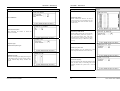
1
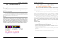
SYS7180VE
PICMG Single Board Computer
For socket 478 CPU With VGA/ LAN
(Pentium 4™&Celeron™& Intel® Celeron®DTM CPU)
User’s Manual
Copyright
This document is copyrighted, © 2004. All rights are reserved. The original
manufacturer reserves the right to make improvements to the products
described in this manual at any time without notice.
No part of this manual may be reproduced, copied, translated or transmitted in
any form or by any means without the prior written permission of the original
manufacturer. Information provided in this manual is intended to be accurate
and reliable. However, the original manufacturer assumes no responsibility for
its use, nor for any infringements upon the rights of third parties that may result
from such use.
Acknowledgments
IBM/AT and PS/2 are trademarks of International Business Machines
Corporation.
Award is a registered trademark of Award Software International, Inc.
Intel®, Celeron™, Pentium 4™ and Pentium 4™ are registered trademarks of
Intel Corporation.
Microsoft Windows is a registered trademark of Microsoft Corporation.
All Other product names or trademarks are properties of their respective
owners.
Liability
The obligation of the warrantor is solely to repair or replace the product. In no
event will the warrantor be liable for any incidental or consequential damages
due to such defect or consequences that arise from inexperienced usage, misuse,
or malfunction of this device.
Additional Information and Assistance
1.
The manufacturer recommends using a grounded plug to ensure proper
motherboard operation. Care should be used in proper conjunction
with a grounded power receptacle to avoid possible electrical shock.
All integrated circuits on this motherboard are sensitive to static
electricity. To avoid damaging components from electrostatic
discharge, please do not remove the board from the anti-static packing
before discharging any static electricity to your body, by wearing a
wrist-grounding strap. The manufacturer is not responsible for any
damage to the motherboard due to improper operation.
2.
Visit the Grantech web site at www.grantech.com.tw where you can
find the latest information about the product.
3.
Contact your distributor, sales representative, or Grantech's customer
service center for technical support if you need additional assistance.
Please have the following information ready before you call:
•Product name and serial number
•Description of your peripheral attachments
•Description of your software (operating system, version, application, etc.)
•A complete description of the problem
•The exact wording of any error messages
Table of Contents
Table of Contents
2.5.10
2.5.11
2.5.12
2.5.13
Table of Contents
CHAPTER 1
INTRODUCTION ...............................................1
1.1
1.2
1.3
1.4
SPECIFICATION ....................................................................1
CHECK LIST ........................................................................1
DESCRIPTION ......................................................................2
POWER REQUIREMENTS ......................................................2
1.5 CONNECTOR & JUMPER LOCATION .........................................4
1.6 BLOCK DIAGRAM ....................................................................5
CHAPTER 2
2.1
2.2
2.3
2.4
2.5
2.5.1
2.5.2
2.5.3
2.5.4
2.5.5
2.5.6
2.5.7
2.5.8
2.5.9
CHAPTER 3
3.1
3.2
3.3
3.4
3.5
3.6
3.7
3.8
3.9
3.10
3.11
3.12
3.13
3.14
3.15
HARDWARE INSTALLATIONS ......................6
INSTALLATION PROCEDURE .................................................6
CPU INSTALLATION:...........................................................7
MAIN MEMORY INSTALLATION: DIMM1/2.........................8
JUMPER SETTINGS:............................................................10
CONNECTORS SETTING: ....................................................12
FRONT PANEL CONNECTOR: J1 .........................................13
USB CONNECTOR: USB1-2 USB3-4 ...............................14
PARALLEL PORT CONNECTOR: LPT ..................................15
SERIAL PORT CONNECTOR: COM1/COM2........................16
IDE PORT CONNECTOR: IDE1/ IDE2................................16
FLOPPY DISK CONNECTOR: FLOPPY...............................17
ADAPTER CONNECTOR FOR 10/100 LAN: LAN1..............18
ADAPTER CONNECTOR FOR GIGA LAN: LAN2 ...............19
EXTERNAL KEYBOARD/MOUSE CONNECTOR:...................20
SYS7180VE User’s Manual
i
VGA CONNECTOR: .......................................................21
KEYBOARD / MOUSE CONNECTOR:...............................21
CPU FAN CONNECTOR: ...............................................21
ACPI CONNECTOR: J2..................................................22
BIOS SETUP ......................................................24
INTRODUCTION .................................................................24
MAIN MENU .....................................................................26
STANDARD CMOS SETUP .................................................28
ADVANCED BIOS FEATURES SETUP..................................30
ADVANCED CHIPSET FEATURES SETUP .............................34
INTEGRATED PERIPHERALS ...............................................38
POWER MANAGEMENT SETUP...........................................43
PNP/PCI CONFIGURATION SETUP .....................................49
PC HEALTH STATUS ..........................................................51
DEFAULTS MENU ..............................................................51
SUPERVISOR/USER PASSWORD SETTING ...........................52
EXIT SELECTING ...............................................................52
POST MESSAGES .............................................................53
POST BEEP ......................................................................53
ERROR MESSAGES ............................................................53
Appendix…………………………………………………………..59
ii
SYS7180VE User’s Manual
CHAPTER 1 – Introduction
CHAPTER 1 – Introduction
PS/2 1 to 2 adapter *1
Com extension cables with bracket *1
Com, Printer extension cables with bracket *1
+12V power cable *1
Chapter 1 Introduction
1.1
Specification
Support Intel® PentiumTM 4 CPU up to 3.06 GHz
Support Intel® CeleronTM CPU up to 2.60 GHz
Support Intel® Celeron®DTM CPU up to 2.80 GHz (Prescott core)
Chipset
Intel®82845GV chipset supports 400/533MHz FSB
Memory
Two 184-pin DDR DIMMs socket, up to 2GB of 266/333MHz
DDR SDRAM
BIOS
Award 4Mbit PnP flash BIOS
VGA
Integrated in 845GV, AGP4X
Share memory up to 64MB with system main-memory
LAN
LAN1: Intel® 82562ET Ethernet controller, supports 10/100M
Base-T
LAN2: (optional)Intel®82540EM Ethernet controller, supports
10/100/1000 Base-T
Wake On LAN support
USB
Four USB ports, Hi-speed USB 2.0
Super I/O
Mini-DIN: 1x PS/2 keyboard/mouse connector
RJ-45: 10/100/1000Mb Ethernet connector
Female DB-15: VGA connector
Box-header: 2* Serial port (2x5Pin);
1*FDD (2x17Pin); 2* EIDE (2x20Pin);
Pin-header: 1*Parallel port (2x13Pin)
Watchdog
System reset or non- maskable interrupt software programmable
time I interval and jumper selectable (64-level)
Operating temperature
0°C ~60°C
Relative humidity
10%~90% non-condensing at temperature of 40BC or
104BF
USB cable *1(Special for SYS7180VE)
Processor
Jumper Short Pin: 6 pcs
1.3
Description
The SYS7180VE is a motherboard based on Intel 845GV chipset and is fully
designed for PC environment. It features socket 478 compatible with Intel’s processor.
This card accommodates up to 2GB of DDR memory.
The SYS7180VE comes with on board CPU temperature sensor to protect your
processor from overheating (Winbond W83627HF chipset). Wired for Management
(WFM) 2.0 specification compliance.
The SYS7180VE has a LAN connector that uses Intel ICH4 integrated with Intel
82562ET (AOL & 10/100) controller.
1.4
Power Requirements
Your system requires a clean, steady power source for reliable performance of the
high frequency CPU on the SYS7180VE Industrial CPU card, the quality of the power
supply is even more important. For the best performance makes sure your power supply
provides a range of 4.75 volts minimum to 5.25 volts maximum DC power source.
Power Consumption
1.2
Check List
For typical configurations, the CPU card is designed to operate with at least a 200W
Please check that your package is complete and contains the items below. If you
discover damaged or missing items, please contact your dealer.
configurations. The power supply must meet the following requirements:
SYS7180VE CPU card
Utility CD for SYS7180VE
Installation Guide
IDE cable *2
FDD cable *1
SYS7180VE User’s Manual
power supply. A higher-wattage power supply should be used for heavily-loaded
Rise time for power supply: 2 ms to 20 ms
Minimum delay for reset to Power Good: 100 ms
Minimum Power down warning: 1 ms
1
2
SYS7180VE User’s Manual
CHAPTER 1 – Introduction
CHAPTER 1 – Introduction
3.3 V output must reach its minimum regulation level within 20ms of the +5V
1.5
output reaching its minimum regulation level
Connector & Jumper Location
The following table lists the power supply’s tolerances for DC voltages:
DC Voltage
+3.3 V
+5 V
+5 VSB (standby)
-5 V
+12 V
-12 V
SYS7180VE User’s Manual
Acceptable Tolerance
±5%
±5%
±5%
±5%
±5%
±5%
3
4
SYS7180VE User’s Manual
CHAPTER 1 – Introduction
1.6
CHAPTER 2 –Hardware Installations
Chapter 2 Hardware Installations
Block Diagram
This chapter provides information on how to use the jumpers and connectors on
the SYS7180VE in order to set up a workable system.
DATA
CTRL
ADDR
DDR266
Modules
FCBGA760
PICMG PCI/ISA SLOT
DATA
CTRL
ADDR
DDR 266 Mhz
BROOKDALE-G
VGA CRT
CONNECTOR
Installation procedure
2.1.1 Insert the system BIOS (if not already installed) genteelly. Pay attention to
the position of pin 1 of BIOS socket.
AGTL+ BUS
GMCH
2.1
CLOCK
ICS950220
SOCKET 478
P4 PROCESSOR
Processor
PWM
2.1.2 Install the processor with correct orientation.
2.1.3 Insert the DRAM module with correct orientation.
2.1.4 Mount the Fan on the top of the processor and connect it to FAN connector.
2.1.5 Insert all external cables except for flat panel. (Hard disk, floppy, keyboard,
Mouse, LAN, etc.)
2.1.6 Prepare a CRT monitor for CMOS setup.
PCI TO ISA
Bridge
W83629D
W83629D
IDE Primary
2.1.7 Confirm the power supply is off.
UDMA66/100
2.1.8 Turn on the power.
PCI CNTRL + PCI ADDR/DATA
IDE Secondary
ICH4
USB 2.0
PORT 1-6
FirmWare Hub
USB I/F
PHY
82562EM
LAN 10/100
RJ45-Connector
GIGA LAN
CONTROLLER
82540
GIGA LAN
Connector
RAID IDE
CONTROLLER
PDC20265R
RAID Primary IDE
Note: The CMOS memory may be in an undefined state at power-on after a period of no
battery backup.
LPC INTERFACE
RAID Secondary IDE
LPC
SUPER-I/O
W83627HF
Floppy
Keyboard
Mouse
AC'97 LINK
COM1
COM2
RS232
RS232 /
422 /
485
SYS7180VE User’s Manual
Parallel
AC'97
CODEC
Audio
Connector
IrDA
5
6
SYS7180VE User’s Manual
CHAPTER 2 –Hardware Installations
2.2
CHAPTER 2 –Hardware Installations
CPU Installation:
2.3
The SYS7180VE Industrial CPU Card supports a single Intel® P4 CeleronTM or
Celeron DTM processor and Pentium 4TM processor. The processor’s VID pins
automatically program the voltage regulator on the CPU card to the required processor
The SYS7180VE Industrial CPU Card supports two single-side or double-sided
DDR266/333 unregistered, DIMM 184-pin sockets for a maximum total memory of 1GB.
Using the non-ECC DDR SDRAM DIMMS.
The CPU card supports the following memory features:
voltage. The host bus speed is automatically selected. The processor connects to the CPU
card through the 478-pins socket.
The CPU card supports the processors listed in table below:
P4 CeleronTM processor
Host Bus frequency
Cache size
400MHz
128KB
Cache size
400MHz / 533MHz
512KB
•
184-pin DIMMs with gold-plated contacts
•
266MHz and 333MHz non-ECC DDR SDRAM
•
Un-buffered single or double-sided DIMMs in the following sizes:
SDRAM
SYNCHRONOUS DRAM (SDRAM) improves memory performance through
memory access that is synchronous with the memory clock. Burst transfer rates at x-1-1-1
timing can be achieved using SDRAM, while asynchronous memory subsystems are
typically limited at x-2-2-2 transfer rates.
Pentium 4TM processor
Host Bus frequency
The CPU card supports single or double-sided DIMMs in the following sizes:
DIMM size
16MB
32MB
64MB
128MB
256MB
Celeron DTM processor
Host Bus frequency
Cache size
533MHz
256KB or 1M
Main Memory Installation: DIMM1/2
The socket-478 comes with a lever to secure the processor. Make sure the notch on
Note:
the corner of the CPU corresponds with the notch on the inside of the socket.
Non-ECC configuration
2Mbit x 64
4Mbit x 64
8Mbit x 64
16Mbit x 64
32Mbit x 64
All memory components and DIMMs used with the SYS7180VE CPU card must
After you have installed the processor into the socket 478, check if the
comply with the PC SDRAM Specification. These include: the PC SDRAM Specification
configuration setup for the CPU type and speed are correct. The CPU should always have a
*memory component specific), the PC Unbuffered DIMM Specification, and the PC Serial
Heat Sink and a cooling fan attached to prevent overheating.
Presence Detect Specification.
Note: Ensure that the CPU heat sink and the CPU top surface are in total contact to avoid
CPU overheating problem that would cause your system to hang or be unstable.
SYS7180VE User’s Manual
7
8
SYS7180VE User’s Manual
CHAPTER 2 –Hardware Installations
CHAPTER 2 –Hardware Installations
Chipset
2.4
Jumper Settings:
Intel 82845GV GMCH overview
The features:
Jumper
400/533 MHz PSB (100/133MHz bus clock)
Jumper setting
Default setting
32-bit addressing for access to 2GB of memory space up to 2GB of 266MHz
FSB
FSB setting: auto
Short 1-2
or 333 MHz DDR SDRAM.
JCC
Clear CMOS: Normal mode
Short 2-3
Supports only for un-buffered non-ECC DIMMs.
JAV
J4
Hub Interface:
-
Supports Hub Interface 1.5
-
266MB/s point-to-point Hub Interface to the ICH4.
-
1.5V operation.
Open
Short 1-2
2.4.1 FSB Setting:
Options
AGP Interface
-
BIOS write-protect: disabled
AT or ATX select: AT
1
2
3
Supports a single 1.5V AGP 2.0 compliant device.
Setting
400
Short 2-3
533
Open
Auto (default)
Short 1-2
Integrated Graphics
-
3D Setup and Render Engine.
-
2D Graphics.
2.4.2 Clear CMOS Setting: JCC
Analog Display Support
Digital Display Channels
1
Options
2
Normal
3
Clear CMOS
Settings
Short 2-3 (default)
Short 1-2
JCC
2.4.3 BIOS Write-protect Setting:JAV
Options
Settings
Disable
Open (default)
Enable
Short 1-2
JAV
SYS7180VE User’s Manual
9
10
SYS7180VE User’s Manual
CHAPTER 2 –Hardware Installations
CHAPTER 2 –Hardware Installations
2.5
2.4.4 AT/ATX Power Setting:J4
Options
1
2
AT
3
ATX
Settings
Connectors
Short 1-2 (default)
Short 2-3
J4
Options
2
3
Setting
IDE1
Secondary IDE Connector
IDE2
J2
VGA Connector
VGA
USB 1_2 Connector
USB1_2 Keyboard/Mouse
USB3_4 CPU Fan Connector
DIMM1
DDR1 184P Connector
Reset
Short 2-3 (default)
COM1 Connector
Disabled
Open
Ethernet 1 RJ-45
KB
CPUFAN
DDR2 184P Connector
DIMM2
COM1
COM2 Connector
COM2
LAN1
Ethernet 2 RJ-45
LAN2
J1
ATX +12V Power
J3
Connector
12
MS
MKB
Connector
USB 3_4 Connector
Short 1-2
Label
ACPI Connector
Printer Port Connector
IRQ11
11
Connectors
FLOPPY PS/2 Mouse Connector
LPT PS/2 Keyboard Connector
Flat Panel Connector
SYS7180VE User’s Manual
Label
Primary IDE Connector
FDD Connector
2.4.5 Watchdog Setting: JWD
1
Connectors Setting:
Connector
Connector
SYS7180VE User’s Manual
CHAPTER 2 –Hardware Installations
CHAPTER 2 –Hardware Installations
2.5.1 Front Panel Connector: J1
2.5.2
USB Connector: USB1-2 USB3-4
This header can be connected to a front panel power switch. The front panel
Note:
connector includes headers for these I/O connections:
Power switch
Power LED
USB cable is special designed for SYS7180VE
The Universal Serial Bus (USB) that allows plug and play computer peripherals
such as keyboard, mouse, joystick, scanner, printer, modem/ISDN, CD-ROM and floppy
This header can be connected to an LED that will light when the computer is
disk drive to be automatically detected when they are attached physically without having to
install drivers or reboot.
powered on.
Hard drive activity LED
The USB connectors allow any of several USB devices to be attached to the
This header can be connected to an LED to provide a visual indicator that data is
computer. Typically, the device driver for USB devices is managed by the operating
being read from or written to an IDE hard drive. For the LED to function properly, the IDE
system. However, because keyboard and mouse support may be needed in the Setup
drive must be connected to the onboard IDE controller.
program before the operating system boots, the BIOS supports USB keyboards and mice.
Speaker
The CPU card has four USB ports; one USB peripheral can be connected to each
A speaker can be installed on the SYS7180VE as a manufacturing option. The
port. For more than four USB devices, an external hub can be connected to either port. The
speaker is enabled by a jumper on pins 2, 4, 6, 8 of the front panel connector. Removing
four USB ports are implemented with stacked back panel connectors. The CPU card fully
the jumper can disable the onboard speaker, and an offboard speaker can be connected in
supports the universal host controller interface (UHCI) and uses UHCI-compatible
its place. The speaker (onboard or offboard) provides error beep code information during
software drivers.
the POST in the event that the computer cannot use the video interface. The speaker is not
USB features includes:
connected to the audio subsystem and does not receive output from the audio subsystem.
Self-identifying peripherals that can be plugged in while the computer is running
Automatic mapping of function to driver and configuration
19 17 15 13 11 9 7
20 18 16 14 12 10 8
5
6
Support for synchronous and asynchronous transfer types over the same set of wires
3 1
4 2
Support for up to 127 physical devices
Guaranteed bandwidth and low latencies appropriate for telephony, audio and other
1-3-5: POWER LED
13-14:POWER ON
19-20: IDE LED
2-4-6-8: SPEAKER
15-16: GREEN LED
7-9: KEYLOCK
17-18: RESET
applications
Error-handling and fault-recovery mechanisms built into the protocol
PIN1— POWER LED+ PIN5—POWER LEDPIN15—GREEN LED+ PIN16—GREEN LEDPIN19—IDE LEDPIN20—IDE LED+
SYS7180VE User’s Manual
13
14
SYS7180VE User’s Manual
CHAPTER 2 –Hardware Installations
CHAPTER 2 –Hardware Installations
2.5.4 Serial Port connector: COM1/COM2
COM1, COM2 are use in the 10-pins box-header, are onboard serial ports of the
CPU card SYS7180VE. The following table shows the pin assignments of these
connectors.
2.5.3 Parallel Port Connector: LPT
COM1/2
Pin
The parallel port bracket can used to add an additional parallel port for additional
1
Data Carrier Detect (DCD)
Compatible (Standard mode)
2
Data Set Ready (DSR)
Bi-Directional (PS/2 compatible)
3
Receive Data (RXD)
Bi-Directional EPP. A driver from the peripheral manufacturer is required for
4
Request to Send (RTS)
operation.
5
Transmit Data (TXD)
Bi-Directional High-speed ECP
6
Clear to Send (CTS)
7
Data Terminal Ready (DTR)
8
Ring Indicator (RI)
9
Ground (GND)
parallel devices. There are four options for parallel port operation:
Pin
1
2
3
4
5
6
7
8
9
10
11
12
13
Description
Description
Strobe#
Data 0
Data 1
Data 2
Data 3
Data 4
Data 5
Data 6
Data 7
Acknowledge#
Busy
Paper Empty#
Printer Select
Pin
14
15
16
17
18
19
20
21
22
23
24
25
Description
Auto Form Feed#
10
9
1
10
2
COM1 / COM2
GND
Error#
Initialize#
Printer Select In#
GND
2.5.5 IDE port Connector: IDE1/ IDE2
GND
GND
The CPU card SYS7180VE provides a bus-mastering PCI IDE interfaces. These
GND
interfaces support PIO Mode 3, PIO Mode 4, ATAPI devices (e.g., CD-ROM), and Ultra
GND
DMA/33/66/100 synchronous-DMA mode transfers. The BIOS supports logical block
GND
addressing (LBA) and extended cylinder head sector (ECHS) translation modes. The BIOS
GND
automatically detects the IDE device transfer rate and translation mode.
GND
Programmed I/O operations usually require a substantial amount of processor
26
bandwidth. However, in multitasking operating systems, the bandwidth freed by bus
mastering IDE can be devoted to other tasks while disk transfers are occurring.
SYS7180VE User’s Manual
15
16
SYS7180VE User’s Manual
CHAPTER 2 –Hardware Installations
CHAPTER 2 –Hardware Installations
2.88 MB, 3.5-inch
These connectors support the provided IDE hard disk ribbon cable. After
connecting the single end to the board, connect the two plugs at the other end to your hard
This connector supports the provided floppy drive ribbon cable. After connecting
disk(s). If you install two hard disks, you must configure the second drive to Slave mode
the single and to the board, connect the two plugs on the other end to the floppy drives.
by setting its jumper accordingly. Please refer to your hard disk documentation for the
jumper setting.
Pin
1
Pin
Description
Pin
Description
Pin
4
Description
1
Reset #
2
GND
3
Data 7
4
Data 8
5
Data 6
6
Data 9
7
Data 5
8
Data 10
9
Data 4
10
Data 11
11
Data 3
12
Data 12
13
Data 2
14
Data 13
15
Data 1
16
Data 14
17
Data 0
18
Data 15
19
GND
20
No connector
21
No connector
22
GND
23
IOW #
24
GND
25
IOR #
26
GND
27
IOCHRDY
28
No connector
29
No connector
30
GND-Default
31
Interrupt
32
No connector
33
SA1
34
No connector
35
SA0
36
SA2
37
HDC CS0 #
38
HDC CSI #
39
HDD Active #
40
GND
7
10
13
16
19
22
25
28
31
34
Description
GND
Pin
2
No connector
GND
5
GND
11
GND
14
Motor enable B#
17
GND
20
Write data#
23
GND
26
Write protect#
29
GND
32
Disk change#
Pin
3
6
Index#
8
Motor enable A#
Description
Reduce write current
9
GND
12
Drive select A#
15
GND
18
STEP#
21
GND
24
Track 0 #
27
GND
30
Side 1 select#
33
Description
GND
No connector
GND
Drive select B#
GND
Direction#
GND
Write gate#
GND
Read data#
GND
2.5.7 Adapter connector for 10/100 LAN: LAN1
This connector is for the LAN adapter that has LED indicate the 10/100Mbps
transfer rate / Link / Act status of Ethernet capability of the CPU card. The follow table
2.5.6 Floppy Disk Connector: FLOPPY
shows the pin assignments of this connector.
The floppy interface can be configured for the following floppy drive capacities
C N13
and sizes:
1
2
3
4
5
6
7
8
360 KB, 5.25-inch
1.2 MB, 5.25-inch
720 KB, 3.5-inch
L in k
LED
1.2 MB, 3.5-inch (driver required)
T r a n s m it
LED
PIN No.
Function
PIN No.
Function
1
TX+
5
GND
2
TX-
6
NC
3
NC
7
RX+
4
GND
8
RX-
1.25/1.44 MB, 3.5-inch
SYS7180VE User’s Manual
17
18
SYS7180VE User’s Manual
CHAPTER 2 –Hardware Installations
CHAPTER 2 –Hardware Installations
2.5.9 External Keyboard/Mouse Connector:
2.5.8 Adapter connector for GIGA LAN: LAN2
There are two 5-pin connectors for external keyboard&mouse.
This connector is for the GIGA LAN adapter that 10/100/1000 Base-TX RJ45
single port (1X1) tab-UP with LEDs integrated magnetics connector. The follow table
shows the pin assignments of this connector.
PIN No. Function
CN18
1
2
3
4
5
Speed
B i- c o l o r
Y /G
LED
SYS7180VE User’s Manual
6
7
8
L in k /A c t
G re e n
LED
1
2
3
4
5
6
7
8
TCT3
TD3TD3+
TD2+
TD2TCT2
TCT4
TD4+
PIN No.
Function
9
10
11
12
TD4TD4+
TD1+
TD110M / OFF
100M / G
1000M / Y
Link / G
Act / Blink
Left
LED
Right
LED
19
20
SYS7180VE User’s Manual
CHAPTER 2 –Hardware Installations
CHAPTER 2 –Hardware Installations
2.5.13 ACPI Connector: J2
2.5.10 VGA Connector:
When used with an ATX-compliant power supply that supports remote power
on/off, the CPU card can turn off the system power through software control.
It is a VGA CRT connector. The pin assignments are as follows:
5
1
6
10
15
11
PIN No.
1
3
5
7
9
11
13
15
Function
Red
Blue
GND
GND
VCC
N.C
H-Sync
DDC clock
PIN No.
2
4
6
8
10
12
14
16
Function
Green
N.C
GND
GND
GND
DDC data
V-Sync
N.C
To enable soft-off control in software, advanced power management must be
enabled in the Setup program and in the operation system. When the system BIOS receives
the correct APM command from the operating system, the BIOS turns off power to the
computer.
With soft off enabled, if power to the computer is interrupted by a power outage or
a disconnected power cord, when power resumes, the computer returns to the power state it
was in before power was interrupted (on or off).
J2
PIN No.
Function
1
5VSB
2
PS_ON
J2
6
5
4
3
2.5.11 Keyboard / Mouse Connector:
Mouse Clock
6
VCC
2
1
Keyboard Clock
5
4
3
Mouse Data
2
GND
PW2
Keyboard Data
1
2.5.12 CPU FAN Connector:
3
GND
4
PWRCTL
5
GND
6
SLEEPSW
PIN No.
Function
PIN No.
Function
4
+12V
2
GND
3
+12V
1
GND
FAN is a 3-pins box-header for the CPU cooling fan power connector. The fan
must be a 12V fan. Pin 3 is for Fan speed sensor input. Pin 2 is for PWM regulating voltage
output.
PIN No. Function Connector type for Cable
FAN1
1
2
3
SYS7180VE User’s Manual
1
GND
2
POWER
3
FAN
Housing: 5102-03 (molex)
Contact: 5103 (molex)
21
22
SYS7180VE User’s Manual
CHAPTER 2 –Hardware Installations
CHAPTER 3 - BIOS SETUP
Chapter 3 BIOS Setup
3.1 Introduction
This chapter discusses Award’s Setup program built into the FLASH ROM BIOS.
The Setup program allows users to modify the basic system configuration. This special
information is then stored in battery-backed RAM so that it retains the Setup information
when the power is turned off.
The rest of this chapter is intended to guide you through the process of configuring
your system using Setup.
Starting Setup
The Award BIOS is immediately activated when you first power on the computer.
The BIOS reads the system information contained in the CMOS and begins the process of
checking out the system and configuring it. When it finishes, the BIOS will seek an
operating system on one of the disks and then launch and turn control over to the operating
system.
While the BIOS is in control, the Setup program can be activated in one of two
ways:
1.
By pressing <Del> immediately after switching the system on, or
2.
by pressing the <Del> key when the following message appears briefly at
the bottom of the screen during the POST (Power On Self-Test).
Press DEL to enter SETUP.
If the message disappears before you respond and you still wish to enter Setup,
restart the system to try again by turning it OFF then ON or pressing the "RESET" button
on the system case. You may also restart by simultaneously pressing <Ctrl>, <Alt>, and
<Delete> keys. If you do not press the keys at the correct time and the system does not
boot, an error message will be displayed and you will again be asked to...
Press F1 to continue, DEL to enter SETUP
Using Setup
In general, you use the arrow keys to highlight items, press <Enter> to select, use
SYS7180VE User’s Manual
23
24
SYS7180VE User’s Manual
CHAPTER 3 - BIOS SETUP
CHAPTER 3 - BIOS SETUP
the PageUp and PageDown keys to change entries, press <F1> for help and press <Esc> to
These defaults have been carefully chosen by both Award and your systems manufacturer
quit. The following table provides more detail about how to navigate in the Setup program
to provide the absolute maximum performance and reliability. Even a seemingly small
using the keyboard.
change to the chipset setup has the potential for causing you to use the override.
Key
Up Arrow
Down Arrow
Left Arrow
Right Arrow
Esc
Move Enter
PgUp key
PgDn key
+ key
- key
Esc key
F1 key
F5 key
F6 key
F7 key
F10 key
Function
A Final Note About Setup
Move to the previous item
Move to the next item
Move to the item on the left (menu bar)
Move to the item on the right (menu bar)
Main Menu: Quit without saving changes
Submenus: Exit Current page to the next higher level menu
Move to the item you desired
Increase the numeric value or make changes
Decrease the numeric value or make changes
Increase the numeric value or make changes
Decrease the numeric value or make changes
Main Menu -- Quit and not save changes into CMOS
Status Page Setup Menu and Option Page Setup Menu -- Exit
current page and return to Main Menu
General help on Setup navigation keys
Load previous values from CMOS
Load the fail-safe defaults from BIOS default table
Load the optimized defaults
Save all the CMOS changes and exit
The information in this chapter is subject to change without notice.
3.2 Main Menu
Once you enter the Award BIOS CMOS Setup Utility, the Main Menu will appear
Getting Help
on the screen. The Main Menu allows you to select from several setup functions and two
Press F1 to pop up a small help window that describes the appropriate keys to use
and the possible selections for the highlighted item. To exit the Help Window press <Esc>
exit choices. Use the arrow keys to select among the items and press <Enter> to accept and
enter the sub-menu.
or the F1 key again.
Note that a brief description of each highlighted selection appears at the bottom of
In Case of Problems
the screen.
If, after making and saving system changes with Setup, you discover that your
computer no longer is able to boot, the Award BIOS™ supports an override to the
CMOS settings which resets your system to its defaults.
The best advice is to only alter settings which you thoroughly understand. To this
end, we strongly recommend that you avoid making any changes to the chipset defaults.
SYS7180VE User’s Manual
25
Setup Items
The main menu includes the following main setup categories. Recall that some systems
may not include all entries.
Standard CMOS Features
Use this menu for basic system configuration.
Advanced BIOS Features
Use this menu to set the Advanced Features available on your system.
26
SYS7180VE User’s Manual
CHAPTER 3 - BIOS SETUP
CHAPTER 3 - BIOS SETUP
Advanced Chipset Features
Use this menu to change the values in the chipset registers and optimize your system's
performance.
Integrated Peripherals
Use this menu to specify your settings for integrated peripherals. See section 6.6. for the
details.
Power Management Setup
Use this menu to specify your settings for power management.
PnP / PCI Configuration
This entry appears if your system supports PnP / PCI.
Load Fail-Safe Defaults
Use this menu to load the BIOS default values for the minimal/stable performance for your
system to operate.
Load Optimized Defaults
Use this menu to load the BIOS default values that are factory settings for optimal
performance system operations. While Award has designed the custom BIOS to maximize
performance, the factory has the right to change these defaults to meet their needs.
Supervisor / User Password
Use this menu to set User and Supervisor Passwords.
Save & Exit Setup
Save CMOS value changes to CMOS and exit setup.
Exit Without Save
Abandon all CMOS value changes and exit setup.
3.3 Standard CMOS Setup
The items in Standard CMOS Setup Menu are divided into 10 categories. Each category
includes no, one or more than one setup items. Use the arrow keys to highlight the item and
then use the <PgUp> or <PgDn> keys to select the value you want in each item.
Main Menu Selections
This table shows the selections that you can make on the Main Menu
Item
Date
Month DD YYYY
Time
HH : MM : SS
Options are in its sub
menu(described in Table 64)
Options are in its sub
menu(described in Table 64)
Options are in its sub
menu(described in Table 64)
Options are in its sub
menu(described in Table 64)
None
360K, 5.25 in
1.2M, 5.25 in
720K, 3.5 in
1.44M, 3.5 in
2.88M, 3.5 in
IDE Primary Master
IDE Primary Slave
IDE Secondary Master
IDE Secondary Master
Drive A
Drive B
SYS7180VE User’s Manual
27
Options
28
Description
Set the system date. Note that the
‘Day’ automatically changes when
you set the date
Set the system time
Press <Enter> to enter the sub
menu of detailed options
Press <Enter> to enter the sub
menu of detailed options
Press <Enter> to enter the sub
menu of detailed options
Press <Enter> to enter the sub
menu of detailed options
Select the type of floppy disk drive
installed in your system
SYS7180VE User’s Manual
CHAPTER 3 - BIOS SETUP
Item
Video
Halt On
Options
EGA/VGA
CGA 40
CGA 80
MONO
All Errors
No Errors
All, but Keyboard
All, but Diskette
All, but Disk/Key
Base Memory
N/A
Extended Memory
N/A
Total Memory
N/A
CHAPTER 3 - BIOS SETUP
Description
Item
Landing zone
Select the default video device
Sector
Select the situation in which you
want the BIOS to stop the POST
process and notify you
Options
Min = 0
Max = 65535
Min = 0
Max = 255
Description
****
Number of sectors per track
3.4 Advanced BIOS Features Setup
This section allows you to configure your system for basic operation. You have the
Displays
the
amount
of
conventional memory detected
during boot up
Displays the amount of extended
memory detected during boot up
Displays the total memory
available in the system
opportunity to select the system’s default speed, boot-up sequence, keyboard operation,
shadowing and security.
IDE Adapters
The IDE adapters control the hard disk drive. Use a separate sub menu to configure each
hard disk drive.
Use the legend keys to navigate through this menu and exit to the main menu. Use Table 3
to configure the hard disk.
Item
Options
IDE HDD
Auto-detection
Press Enter
IDE Primary Master
None
Auto
Manual
Capacity
Auto Display your disk
drive size
Description
Press Enter to auto-detect the HDD on this
channel. If detection is successful, it fills the
remaining fields on this menu.
Selecting ‘manual’ lets you set the remaining fields
on this screen. Selects the type of fixed disk.
"User Type" will let you select the number of
cylinders, heads, etc. Note: PRECOMP=65535
means NONE !
Disk drive capacity (Approximated). Note that this
size is usually slightly greater than the size of a
formatted disk given by a disk checking program.
Virus Warning
When enabled, you receive a warning message if a program (specifically, a virus) attempts
to write to the boot sector or the partition table of the hard disk drive. You should then run
an anti-virus program. Keep in mind that this feature protects only the boot sector, not the
entire hard drive.
Normal
LBA
Choose the access mode for this hard disk
Large
Auto
The following options are selectable only if the ‘IDE Primary Master’ item is set to ‘Manual’
Min = 0
Cylinder
Set the number of cylinders for this hard disk.
Max = 65535
Min = 0
Head
Set the number of read/write heads
Max = 255
Min = 0
**** Warning: Setting a value of 65535 means no
Precomp
Max = 65535
hard disk
NOTE: Many disk diagnostic programs that access the boot sector table can trigger the
Access Mode
SYS7180VE User’s Manual
virus warning message. If you plan to run such a program, we recommend that you first
disable the virus warning.
Enabled
29
30
Activates automatically when the system
boots up causing a warning message to
appear when anything attempts to access the
boot sector or hard disk partition table.
SYS7180VE User’s Manual
CHAPTER 3 - BIOS SETUP
Disabled
No warning message will appear when
anything attempts to access the boot sector or
hard disk partition table.
Description
Choice
CHAPTER 3 - BIOS SETUP
Description
Choice
Boot Up NumLock Status
Toggle between On or Off to control the state of
the NumLock key when the system boots. When
toggled On, the numeric keypad generates
numbers instead of controlling cursor operations.
CPU L1/L2 Cache ECC Checking
When you select Enabled, memory checking is
enabled when the external cache contains ECC
SRAMs.
Gate A20 option
Gate A20 refers to the way the system addresses
memory above 1 MB (extended memory). When
set to Fast, the system chipset controls Gate A20.
When set to Normal, a pin in the keyboard
controller controls Gate A20. Setting Gate A20 to
Fast improves system speed, particularly with
OS/2 and Windows
Quick Power On Self Test
Select Enabled to reduce the amount of time
required to run the power-on self-test (POST). A
quick POST skips certain steps. We recommend
that you normally disable quick POST. Better to
find a problem during POST than lose data
during your work
Typematic Rate Setting
When Disabled, the following two items
(Typematic Rate and Typematic Delay) are
irrelevant. Keystrokes repeat at a rate determined
by the keyboard controller in your system. When
Enabled, you can select a typematic rate and
typematic delay.
First/Second/Third/Other Boot Device
The BIOS attempts to load the operating system
from the devices in the sequence selected in these
items.
Typematic Rate (Chars/Sec)
When the typematic rate setting is enabled, you
can select a typematic rate (the rate at which
character repeats when you hold down a key) of
6, 8, 10,12, 15, 20, 24 or 30 characters per
second.
Swap Floppy Drive
This field is effective only in systems with two
floppy drives. Selecting Enabled assigns
physical drive B to logical drive A, and physical
drive A to logical drive B.
If the system has two floppy drives, you can
swap the logical drive name assignments.
SYS7180VE User’s Manual
31
32
SYS7180VE User’s Manual
CHAPTER 3 - BIOS SETUP
Description
CHAPTER 3 - BIOS SETUP
3.5 Advanced Chipset Features Setup
Choice
Typematic Delay (Msec)
When the typematic rate setting is enabled, you
can select a typematic delay (the delay before
key strokes begin to repeat) of 250, 500, 750 or
1000 milliseconds.
Security Option
Select whether the password is required every
time the system boots or only when you enter
setup. If you have set a password, select whether
the password is required every time the System
boots, or only when you enter Setup.
System: The system will not boot and access to
Setup will be denied if the correct password is
not entered at the prompt.
Setup: The system will boot, but access to Setup
will be denied if the correct password is not
entered at the prompt.
This section allows you to configure the system based on the specific features of
the installed chipset. This chipset manages bus speeds and access to system memory
Note: To disable security, select PASSWORD SETTING at Main Menu and then you will be
asked to enter password. Do not type anything and just press <Enter>, it will disable security.
Once the security is disabled, the system will boot and you can enter Setup freely.
resources, such as DRAM and the external cache. It also coordinates communications
between the conventional ISA bus and the PCI bus. It must be stated that these items
should never need to be altered. The default settings have been chosen because they
provide the best operating conditions for your system. The only time you might consider
OS Select For DRAM > 64MB
making any changes would be if you discovered that data was being lost while using your
Select OS2 only if you are running OS/2
operating system with greater than 64 MB of
RAM on your system.
system.
Description
Choice
DRAM Timing Selectable
The value in this field depends on performance
parameters of the installed memory chips
(DRAM). Do not change the value from the
factory setting unless you install new memory
that has a different performance rating than the
original DRAMs
Report No FDD For Win 95
Select Yes to release IRQ6 when the system
contains no floppy drive, for compatibility
with Windows 95 logo certification. In the
Integrated Peripherals screen, select
Disabled for the Onboard FDC Controller
field.
SYS7180VE User’s Manual
33
34
SYS7180VE User’s Manual
CHAPTER 3 - BIOS SETUP
Description
Choice
Description
CAS Latency Time
When synchronous DRAM is installed, the
number of clock cycles of CAS latency depends
on the DRAM timing. Do not reset this field
from the default value specified by the system
designer.
You can select CAS latency time in HCLK of
2/2 or 3/3. The system board designer should set
the values in this field, depends on the DRAM
installed specifications of the installed DRAM
or the installed CPU.
Choice
Memory Frequency for
Select
the
memory
frequency
for
DDR200/DDR266 when install the memory with
specification of DDR200, or when install the
memory with specification of DDR266, or Auto
define by the BIOS.
System BIOS Cacheable
Selecting Enabled allows caching of the system
BIOS ROM at F0000h-FFFFFh, resulting in
better system performance. However, if any
program writes to this memory area, a system
error may result.
Active to Precharge delay
Select the precharge delay timer.
DRAM RAS# to CAS# delay
This field lets you insert a timing delay between
the CAS and RAS strobe signals, used when
DRAM is written to, read from, or refreshed.
Fast gives faster performance; and Slow gives
more stable performance. This field applies only
when synchronous DRAM is installed in the
system.
Video BIOS Cacheable
Selecting Enabled allows caching of the video
BIOS ROM at C0000h to C7FFFh, resulting in
better video performance. However, if any
program writes to this memory area, a system
error may result.
Memory Hole At 15M-16M
You can reserve this area of system memory for
ISA adapter ROM. When this area is reserved, it
cannot be cached. The user information of
peripherals that need to use this area of system
memory usually discusses their memory
requirements.
DRAM RAS# Precharge
The precharge time is the number of cycles it
takes for the RAS to accumulate its charge
before DRAM refresh. If insufficient time is
allowed, refresh may be incomplete and the
DRAM may fail to retain data.
SYS7180VE User’s Manual
CHAPTER 3 - BIOS SETUP
35
36
SYS7180VE User’s Manual
CHAPTER 3 - BIOS SETUP
Description
Choice
CHAPTER 3 - BIOS SETUP
Description
Delay Transaction
The chipset has an embedded 32-bit posted write
buffer to support delay transactions cycles.
Select Enabled to support compliance with PCI
specification version 2.1.
Choice
On chip Frame buffer size
When Enabled, a fixed VGA frame buffer from
A000h to BFFFh and a CPU-to-PCI write buffer
are implemented.
3.6 Integrated Peripherals
Delay Prior to Thermal
Select the interval to setup the delay timer for
CPU Thermal-Throttling.
AGP Aperture Size (MB)
Select the size of the Accelerated Graphics Port
(AGP) aperture. The aperture is a portion of the
PCI memory address range dedicated for
graphics memory address space. Host cycles that
hit the aperture range are forwarded. Host cycles
that hit the aperture range are forwarded to the
AGP without any translation.
On-Chip VGA setting
On-Chip VGA
When Enabled to choice the on-board VGA
function, otherwise disabled the on-board VGA
function.
Description
SYS7180VE User’s Manual
37
38
Choice
SYS7180VE User’s Manual
CHAPTER 3 - BIOS SETUP
Description
Choice
CHAPTER 3 - BIOS SETUP
Description
On-Chip Primary PCI IDE
IDE Secondary Master/Slave PIO
The integrated peripheral controller contains
an IDE interface with support for two IDE
channels. Select Enabled to activate each
channel separately.
The
four
IDE
PIO
(Programmed
Input/Output) fields let you set a PIO mode
(0-4) for each of the four IDE devices that
the onboard IDE interface supports. Modes 0
through 4 provide successively increased
performance. In Auto mode, the system
automatically determines the best mode for
each device.
IDE Primary Master/Slave PIO
IDE Secondary Master/Slave UDMA
The
four
IDE
PIO
(Programmed
Input/Output) fields let you set a PIO mode
(0-4) for each of the four IDE devices that
the onboard IDE interface supports. Modes 0
through 4 provide successively increased
performance. In Auto mode, the system
automatically determines the best mode for
each device.
UDMA (Ultra DMA) is a DMA data transfer
protocol that utilizes ATA commands and the
ATA bus to allow DMA commands to
transfer data at a maximum burst rate of 33
MB/s. When you select Auto in the four IDE
UDMA fields (for each of up to four IDE
devices that the internal PCI IDE interface
supports),
the
system
automatically
determines the optimal data transfer rate for
each IDE device.
IDE Primary Master/Slave UDMA
UDMA (Ultra DMA) is a DMA data transfer
protocol that utilizes ATA commands and the
ATA bus to allow DMA commands to
transfer data at a maximum burst rate of 33
MB/s. When you select Auto in the four IDE
UDMA fields (for each of up to four IDE
devices that the internal PCI IDE interface
supports),
the
system
automatically
determines the optimal data transfer rate for
each IDE device.
Choice
USB Controller
Select Enabled if your system contains a
Universal Serial Bus (USB) controller and
you have USB peripherals.
On-Chip Secondary PCI IDE
USB 2.0 controller
The integrated peripheral controller contains
an IDE interface with support for two IDE
channels. Select Enabled to activate each
channel separately.
SYS7180VE User’s Manual
Select Enabled if your system contains a
Universal Serial Bus (USB 2.0) controller
and you have USB peripherals.
39
40
SYS7180VE User’s Manual
CHAPTER 3 - BIOS SETUP
Description
Choice
CHAPTER 3 - BIOS SETUP
Description
Choice
sector the drive can support.
USB Keyboard Support
Onboard FDC Controller
Select Enabled if your system contains a
Universal Serial Bus (USB) controller and
you have a USB keyboard.
Select Enabled if your system has a floppy
disk controller (FDC) installed on the system
board and you wish to use it. If you install
and-in FDC or the system has no floppy
drive, select Disabled in this field.
AC’97 Audio
Onboard Serial Port 1
Select Enabled to use the audio capabilities
of your system. Most of the following fields
do not appear when this field is Disabled.
Select a logical COM port name and
matching address for the first and second
serial ports. Select an address and
corresponding interrupt for the first and
second serial ports.
Init Display First
Onboard Serial Port 2
Initialize the AGP video display before
initializing any other display device on the
system. Thus the AGP display becomes the
primary display.
Select a logical COM port name and
matching address for the first and second
serial ports. Select an address and
corresponding interrupt for the first and
second serial ports.
Onboard CNR LAN control
Select Enabled to active the onboard
10/100-LAN controller, select Disabled to
turn-off the onboard 10/100-LAN controller
when you do not want to use this function.
Onboard Parallel Port
Select a logical LPT port name and matching
address for the physical parallel (printer) port
IDE HDD Block mode
Block mode is also called block transfer,
multiple commands, or multiple sector
read/write. If your IDE hard drive supports
block mode (most new drives do), select
Enabled for automatic detection of the
optimal number of block read/writes per
sector the drive can support
SYS7180VE User’s Manual
41
42
SYS7180VE User’s Manual
CHAPTER 3 - BIOS SETUP
Description
CHAPTER 3 - BIOS SETUP
Choice
Parallel Port Mode
Selected an operating mode for the onboard
parallel port. Select Compatible or extended
unless you are certain both your hardware
and software support EPP or ECP mode.
PWRON After PWR-Fail
Select a Power On status by the BIOS setup
when power fail.
3.7 Power Management Setup
The Power Management Setup allows you to configure you system to most
Description
Choice
effectively save energy while operating in a manner consistent with your own style of
computer use.
ACPI function
Select to Enabled the ACPI function and
select Disabled to disable the APCI.
Power management
SYS7180VE User’s Manual
43
44
SYS7180VE User’s Manual
CHAPTER 3 - BIOS SETUP
Description
Choice
CHAPTER 3 - BIOS SETUP
Description
Choice
HDD Power Down
Video Off Method
When enabled and after the set time of
system inactivity, the hard disk drive will
be powered down while all other devices
remain active.
Video Off In Suspend
This determines the manner in which the
monitor is blanked.
Soft-Off by PWR-BTTN
When enabled, turning the system off with
the on/off button places the system is a
very low-power-usage state, with only
enough circuitry receiving power to detect
power button activity or Resume by Ring
activity.
Suspend Type
Select the Suspend Type.
Wake up by PCI card
When Enabled, your can awakens the system
from Suspend mode from a PCI card event.
MODEM Use IRQ
Name the interrupt request (IRQ) line assigned
to the modem (if any) on your system. Activity
of the selected IRQ always awakens the
system.
SYS7180VE User’s Manual
Power On by Ring
An input signal on the serial Ring Indicator (RI)
line (in other words, an incoming call on the
modem) awakens the system from a soft off
state.
45
46
SYS7180VE User’s Manual
CHAPTER 3 - BIOS SETUP
Description
Choice
CHAPTER 3 - BIOS SETUP
Description
Choice
Reload Global Timer Events: When Enabled, an event occurring on each listed device restarts the
global timer for Standby mode.
Resume by Alarm
When Enabled, your can set the date and time at
which the RTC (real-time clock) alarm awakens
the system from Suspend mode.
SYS7180VE User’s Manual
47
48
SYS7180VE User’s Manual
CHAPTER 3 - BIOS SETUP
CHAPTER 3 - BIOS SETUP
IRQ n Resources
3.8 PnP/PCI Configuration Setup
This section describes configuring the PCI bus system. PCI, or Personal Computer
Interconnect, is a system which allows I/O devices to operate at speeds nearing the speed
the CPU itself uses when communicating with its own special components. This section
covers some very technical items and it is strongly recommended that only experienced
users should make any changes to the default settings.
When resources are controlled manually, assign each system interrupt as on of the
following type, depending on the type of device using the interrupt.
Legacy ISA Devices compliant with the original PC AT bus specification, requiring a
specific interrupt (Such as IRQ4 for serial port 1)
PCI/ISA PnP Devices compliant with the Plug and Play standard, whether designed for
PCI or ISA bus architecture.
The Choice: Legacy ISA and PCI/ISA PnP.
Description
Choices
PCI/VGA Palette Snoop
Leave this field at Disabled.
Resource Controlled by
The Award Plug and Play BIOS can
automatically configure all the boot and Plug
and Play – compatible devices. If you select
Auto, all the interrupt request (IRQ) and DMA
assignment fields disappear, as the BIOS
automatically assigns them
Reset Configuration Data
Normally, you leave this field Disabled. Select
Enabled
to
reset
Extended
System
Configuration Data (ESCD) when you exit
Setup if you have installed a new add-on and the
system reconfiguration has caused such a
serious conflict that the operating system can
not boot.
SYS7180VE User’s Manual
49
50
SYS7180VE User’s Manual
CHAPTER 3 - BIOS SETUP
CHAPTER 3 - BIOS SETUP
3.9 PC Health Status
3.11 Supervisor/User Password Setting
You can set either supervisor or user password, or both of then. The differences between
are:
SUPERVISOR PASSWORD: can enter and change the options of the setup menus.
USER PASSWORD: just can only enter but do not have the right to change the options of
the setup menus. When you select this unction, the following message will appear at the
center of the screen to assist you in creating a password.
ENTER PASSWORD:
Type the password, up to eight characters in length, and press <Enter>. The password
typed now will clear any previously entered password from CMOS memory. You will be
asked to confirm the password. Type the password again and press <Enter>. You may also
press <Esc> to abort the selection and not enter a password.
The BIOS shows the PC health status in this window.
Item
To disable a password, just press <Enter> when you are prompted to enter the password. A
Description
Current CPU Temp.
Current System Temp.
Current CPUFAN Speed
+12V / -12V / +5V / -5V / +3.3V
/ VBAT
This field displays the current CPU temperature, if your
computer contains a monitoring system.
This field displays the current system temperature, if your
computer contains a monitoring system.
These fields display the current speed of up to three CPU fans,
if your computer contains a monitoring system.
These fields display the current voltage of input lines, if your
computer contains a monitoring system.
message will confirm the password will be disabled. Once the password is disabled, the
system will boot and you can enter Setup freely.
PASSWORD DISABLED.
When a password has been enabled, you will be prompted to enter it every time you try to
enter Setup. This prevents an unauthorized person from changing any part of your system
configuration.
Additionally, when a password is enabled, you can also require the BIOS to request a
3.10 Defaults Menu
password every time your system is rebooted. This would prevent unauthorized use of your
Selecting “Defaults” from the main menu shows you, which are described below
computer.
You determine when the password is required within the BIOS Features Setup Menu and
its Security option (see Section 3). If the Security option is set to “System”, the password
Load Optimized Defaults
When you press <Enter> on this item you get a confirmation dialog box
will be required both at boot and at entry to Setup. If set to “Setup”, prompting only occurs
with a message similar to:
when trying to enter Setup.
Load Optimized Defaults (Y/N) ? N
3.12 Exit Selecting
Pressing ‘Y’ loads the default values that are factory settings for optimal
Save & Exit Setup
performance system operations.
SYS7180VE User’s Manual
51
52
SYS7180VE User’s Manual
CHAPTER 3 - BIOS SETUP
CHAPTER 3 - BIOS SETUP
CMOS checksum error
Pressing <Enter> on this item asks for confirmation:
Checksum of CMOS is incorrect. This can indicate that CMOS has become corrupt. This
Save to CMOS and EXIT (Y/N)? Y
Pressing “Y” stores the selections made in the menus in CMOS – a special section of
error may have been caused by a weak battery. Check the battery and replace if necessary.
DISK BOOT failure
memory that stays on after you turn your system off. The next time you boot your
computer, the BIOS configures your system according to the Setup selections stored in
INSERT SYSTEM DISK AND PRESS ENTER
CMOS. After saving the values the system is restarted again.
No boot device was found. This could mean that either a boot drive was not detected or the
Exit Without Saving
drive does not contain proper system boot files. Insert a system disk into Drive A: and
press <Enter>. If you assumed the system would boot from the hard drive, make sure the
Pressing <Enter> on this item asks for confirmation:
controller is inserted correctly and all cables are properly attached. Also be sure the disk is
Quit without saving (Y/N)? Y
formatted as a boot device. Then reboot the system.
This allows you to exit Setup without storing in CMOS any change. The previous
selections remain in effect. This exits the Setup utility and restarts your computer.
Diskette drives or types mismatch error
RUN SETUP
3.13 POST Messages
Type of diskette drive installed in the system is different from the CMOS definition. Run
During the Power On Self-Test (POST), if the BIOS detects an error requiring you to do
Setup to reconfigure the drive type correctly.
Display switch is set incorrectly
something to fix, it will either sound a beep code or display a message.
Display switch on the motherboard can be set to either monochrome or color. This
If a message is displayed, it will be accompanied by:
indicates the switch is set to a different setting than indicated in Setup. Determine which
PRESS F1 TO CONTINUE, CTRL-ALT-ESC OR DEL TO ENTER SETUP
setting is correct, and then either turn off the system and change the jumper, or enter Setup
and change the VIDEO selection.
3.14 POST Beep
Display type has changed since last BOOT
Currently there are two kinds of beep codes in BIOS. This code indicates that a video error
Since last powering off the system, the display adapter has been changed. You must
has occurred and the BIOS cannot initialize the video screen to display any additional
configure the system for the new display type.
information. This beep code consists of a single long beep followed by two short beeps.
EISA configuration checksum error
The other code indicates that your DRAM error has occurred. This beep code consists of a
PLEASE RUN EISA CONFIGURATION UTILITY
single long beep repeatedly.
The EISA non-volatile RAM checksum is incorrect or cannot correctly read the EISA slot.
This can indicate either the EISA non-volatile memory has become corrupt or the slot has
3.15 Error Messages
been configured incorrectly. Also be sure the card is installed firmly in the slot.
One or more of the following messages may be displayed if the BIOS detects an error
during the POST. This list includes messages for both the ISA and the EISA BIOS.
EISA configuration is not complete
PLEASE RUN EISA CONFIGURATION UTILITY
CMOS battery has failed
The slot configuration information stored in the EISA non-volatile memory is incomplete.
CMOS battery is no longer functional. It should be replaced.
SYS7180VE User’s Manual
53
54
SYS7180VE User’s Manual
CHAPTER 3 - BIOS SETUP
Note: When either of these errors appear, the system will boot in ISA mode, which
allows you to run the EISA Configuration Utility.
Error encountered initializing hard drive
CHAPTER 3 - BIOS SETUP
the memory map for your system to find and replace the bad memory chips.
Memory size has changed since last BOOT
Memory has been added or removed since the last boot. In EISA mode use Configuration
Hard drive cannot be initialized. Be sure the adapter is installed correctly and all cables are
Utility to reconfigure the memory configuration. In ISA mode enter Setup and enter the
correctly and firmly attached. Also be sure the correct hard drive type is selected in Setup.
new memory size in the memory fields.
Error initializing hard disk controller
Memory verify error at ...
Cannot initialize controller. Make sure the cord is correctly and firmly installed in the bus.
Indicates an error verifying a value already written to memory. Use the location along with
Be sure the correct hard drive type is selected in Setup. Also check to see if any jumper
your system's memory map to locate the bad chip.
needs to be set correctly on the hard drive.
Offending address not found
Floppy disk controller error or no controller present
This message is used in conjunction with the I/O CHANNEL CHECK and RAM PARITY
Cannot find or initialize the floppy drive controller. Make sure the controller is installed
ERROR messages when the segment that has caused the problem cannot be isolated.
correctly and firmly. If there are no floppy drives installed, be sure the Diskette Drive
Offending segment
selection in Setup is set to NONE.
This message is used in conjunction with the I/O CHANNEL CHECK and RAM PARITY
Invalid EISA configuration
ERROR messages when the segment that has caused the problem has been isolated.
PLEASE RUN EISA CONFIGURATION UTILITY
Press a key to REBOOT
The non-volatile memory containing EISA configuration information was programmed
This will be displayed at the bottom screen when an error occurs that requires you to reboot.
incorrectly or has become corrupt. Re-run EISA configuration utility to correctly program
Press any key and the system will reboot.
the memory.
Press F1 to disable NMI, F2 to REBOOT
NOTE: When this error appears, the system will boot in ISA mode, which
allows you to run the EISA Configuration Utility.
Keyboard error or no keyboard present
When BIOS detects a Non-maskable Interrupt condition during boot, this will allow you to
disable the NMI and continue to boot, or you can reboot the system with the NMI enabled.
RAM parity error
Cannot initialize the keyboard. Make sure the keyboard is attached correctly and no keys
CHECKING FOR SEGMENT ...
are being pressed during the boot.
Indicates a parity error in Random Access Memory.
If you are purposely configuring the system without a keyboard, set the error halt condition
in Setup to HALT ON ALL, BUT KEYBOARD. This will cause the BIOS to ignore the
Should be empty but EISA board found
PLEASE RUN EISA CONFIGURATION UTILITY
missing keyboard and continue the boot.
A valid board ID was found in a slot that was configured as having no board ID.
Memory address error at ...
NOTE; When this error appears, the system will boot in ISA mode, which
allows you to run the EISA Configuration Utility.
Indicates a memory address error at a specific location. You can use this location along
with the memory map for your system to find and replace the bad memory chips.
Should have EISA board but not found
Memory parity error at ...
PLEASE RUN EISA CONFIGURATION UTILITY
Indicates a memory parity error at a specific location. You can use this location along with
SYS7180VE User’s Manual
55
56
SYS7180VE User’s Manual
CHAPTER 3 - BIOS SETUP
The board installed is not responding to the ID request, or no board ID has been found in
CHAPTER 3 - BIOS SETUP
is also used for M/B burn in test.
BIOS ROM checksum error - System halted
the indicated slot.
NOTE: When this error appears, the system will boot in ISA mode, which
allows you to run the EISA Configuration Utility.
The checksum of ROM address F0000H-FFFFFH is bad.
Memory test fail
BIOS reports the memory tests fail if the onboard memory is tested error.
Slot not empty
Indicates that a slot designated as empty by the EISA Configuration Utility actually contains a board.
NOTE: When this error appears, the system will boot in ISA mode, which allows you to run the EISA
Configuration Utility.
System halted, (CTRL-ALT-DEL) to REBOOT ...
Indicates the present boot attempt has been aborted and the system must be rebooted. Press and hold
down the CTRL and ALT keys and press DEL.
Wrong board in slot
PLEASE RUN EISA CONFIGURATION UTILITY
The board ID does not match the ID stored in the EISA non-volatile memory.
NOTE: When this error appears, the system will boot in ISA mode, which allows you
to run the EISA Configuration Utility.
Floppy disk(s) fail (80)
Unable to reset floppy subsystem.
Floppy disk(s) fail (40)
Floppy Type dismatch.
Hard disk(s) fail (80)
HDD reset failed.
Hard disk(s) fail (40)
HDD controller diagnostics failed.
Hard disk(s) fail (20)
HDD initialization error.
Hard disk(s) fail (10)
Unable to recalibrate fixed disk.
Hard disk(s) fail (08)
Sector Verify failed.
Keyboard is locked out - Unlock the key.
Unlock the key. BIOS detect the keyboard is locked. P17 of keyboard controller is pulled low.
Keyboard error or no keyboard present
Cannot initialize the keyboard. Make sure the keyboard is attached correctly and no keys are being
pressed during the boot.
Manufacturing POST loop
System will repeat POST procedure infinitely while the P15 of keyboard controller is pulling low. This
SYS7180VE User’s Manual
57
58
SYS7180VE User’s Manual
CHAPTER 3 - BIOS SETUP
APPENDIX
CHAPTER 3 - BIOS SETUP
NOTE: Because WIN NT,win2000,win2003,winXP are not effective by
writing the port directly, so we must make lib file、driver or DLL first.
Watch-Dog-Timer (WDT) Setting
一. Definition for SYS7180VE watchdog
The watchdog timer can be adjusted by software setting from
1second to 239seconds or from 1 minute to 239 minutes. The I/O port is
defined at address EFH. You can trigger/enable disable the timer by
writing port EFH.
F0H: timer for minute
F1H: timer for second
0:
disable the timer
二. Test procedure in DOS
Implement Debug order in MS-DOS:
o ef f1
o ef 5
[ enter]
The system will reset after 5 seconds
三. Assembly language example
Timer for second:
mov AL, f1
mov dx, ef
out
dx, AL
mov AL, 65 (time for 65 sec. decimal system )
mov dx, ef
out dx, AL
Timer for minute:
mov AL, f0
mov dx, ef
out
dx, AL
mov AL, 75 (time for 75 min. decimal system )
mov dx, ef
out dx, AL
Disable the watchdog-timer:
mov AL, 0
mov dx, ef
out
dx, AL
SYS7180VE User’s Manual
59
60
SYS7180VE User’s Manual