1
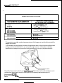
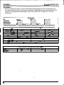
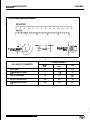
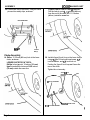
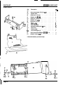
BC4050 BAGGER CART
HONDA TRACTOR APPLICATIONS
Lower Chute: H/C 2377786
Bolt: H/C 2377836 (Qty. 2)
Washer: H/C 3336112 (Qty. 2)
HT3810
HT3813
~~
~
H4013
H4514/CD4538
H4518/CD4538C
Lower Chute: H/C 3477536
Lower Chute Pin: H/C 3477601
1
I
BK4542 Blower Kit
BK4546 Blower Kit
This operator’s manual is considered a permanent part of the bagger cart and should remain with the
bagger cart if resold.
The information and specifications included in this publication were in effect at the time of approval for
printing. American Honda Motor Co., Inc. reserves the right, however, to discontinue or change
specifications or design at any time without notice and without incurring any obligation whatever.
LOCATION
Record the frame serial number for your.futurereference. Refer to the model number and frame serial
number when ordering parts, and when making technical or warranty inquiries (see page 21)
Model number: BC4050
.Frame serial number: BC1
-
I
Safety Messages
Your safety and the safety of others are very important. We have provided important
safety messages in this manual. Please read these messages carefully.
A safety message alerts you to potential hazards that could hurt you or others. Each
and one of three words:
safety message is preceded by a safety alert symbol
DANGER, WARNING, or CAUTION.
A
These mean:
You WILL be KILLED or SERIOUSLY HURT if you don’t
follow instructions.
You CAN be KILLED or SERIOUSLY HURT if you don’t
follow instructions.
You CAN be HURT if you don’t follow instructions.
Each message tells you what the hazard is, what can happen, and what you can do to
avoid or reduce injury.
Damage Prevention Messages
You will also see other important messages that are preceded by the word NOTICE.
This word means:
1-
Your bagger cart or other property can be damaged ifyou
don’t follow instructions.
The purpose of these messages is to help prevent damage to your bagger cart, other
property, or the environment.
BC4050 BAGGER CART
CONTENTS
CONTENTS
ASSEMBLY
1
Assembly and hook-up information.
OPERATION
9
How to haul and dump grass safely. How to hook up and remove your bagger cart.
How to convert the cart for hauling other loads.
Safety . . . . . . . . . . . . . . . . . . . . . . . . . . . . . . . . . . . . . . . . .
Connecting and Disconnecting the Cart
.
.. ... . ..... ..
.. ...
. .
.
Unloading the Cart . . . . . . . . . . . . . . . . . . . . . . . . . . . . . . . . . .
Removing the Cover Assembly to Haul Other Loads . . . . . . . . . . . . . . . .
a
9
10
11
14
15
MAINTENANCE
How to perform routine inspection and service to keep your bagger cart in good
operating condition.
. . . . . . . . . . . .. . . . .. . . . . . . . . . . . . .. . . .
15
.........................................
Wheels. . . . . . . . . , . . . . . . . . . . . . . . . . . . . . . . . . . . . . . .
15
15
Cover Assembly
Tires
SPECIFICATIONS
17
Dimensions, capacities, and other technical information.
PARTS LIST
19
Illustrations and descriptions for identifying any replacement parts you may need.
CUSTOMER SERVICE INFORMATION
How to contact us if you have a question or a warranty problem.
21
ASSEMBLY
BC4050 BAGGER CART
ASSEMBLY
1. Remove all parts from the box. There are three bags containing fasteners for the cart assembly, the
hitch plate installation and the discharge chute assembly. To facilitate assembly, sort the fasteners into
groups for the appropriate assembly stages. Refer to the PARTS LIST on pages 18 - 20 for part
identification.
Components
Box
Support Tube
Swivel Wheel (2)
Dump Cloth Rod
FraffM
Support Rod
Vinyl Cover
Connecting Sleeve, 9 x 20"
U-Bracket
Frame Rod
Hitch Bracket
Flex Hose, 8 1R x 30"
Latch Handle
Straight Rod
Dump Cloth
Middle Chute
-
Cart Assembly Hardware Bag (Steps 1 16)
Hex Bolt, 5/16 x 1 1R" (4)
Cotter Circle, 1' 1/8" (4)
Locknut (nylon insert), 9 16"
Pan Head Screw, 114 x 1/4" (6)
Locknut, 112- (2)
sleeve Clamp (2)
Locknut, 5116 (4)
Spring Washer, 5116" (2)
Hex Nut, 5/16" (3)
Hex Bolt, It2 x 1 114" (2)
Locknut, 3/8"
Spacer, 5/16" (2)
Flatwasher, 5/16' (9)
Rubber Strap, 6"
Hex Bolt, 5/16 x 314"
Pan Head Screw, 5/16 x 34"(3) Lockwasher, 5/16" (3)
Lockwasher, 1/4"
Hex nut. 1/4"
Hex Bolt, 3/8 x 1" (8)
Flatwasher, 3/8"(10 )
Locknut (nylon insert), 1/4" (2)
-
Hitch Bracket Assembly Hardware Bag (Steps 17 18)
IHex Bolt, 8 x 20 mm(4)
Clevis Pin, lL?
x 1 1/4" (2)
Hex Bolt. 1R x 1"
1 Safety Clip (2)
S-Hook (3)
Rubber Strap 9 (1 hook), 6' (3) Pan Head Screw, 5/16 x 314"
Locknut, 3 16"
Flatwasher, 5/16" (6)
ILockwasher. 1R"
[ Lockwasher, 8 mm (4)
I Hex Nut. 112"
I
-
Chute Assembly Hardware Bag (Steps 19 23)
Slotted Truss Head Screw,
9 16 x 3 4 " (2)
IV
Pan head Screw, 5/16 x 1" (3)
Fender Washer, 5/16 x 1 1/4 (2)
BC4050 BAGGER CART
ASSEMBLY
FASTENER MEASUREMENT
I
I
V
/
NursAREs
BY INSIDE D
AT THREAD MPM
WASHERS ARE SPECtFlED
BY NSIDE DIAM€IER
I
NUT AND BOLT DIAMETER
.
TORQUE VALUES
ft-l b
kg-m
N.m
8 mm Bolts
15
2.1
21
1/4 inch nuts and bolts
7
1.o
10
5/16 nuts and bolts
14
1.9
19.
3/8 inch nuts and bolts
25
3.5
34
1/2 inch nuts and bolts
60
8.3
81
ASSEMBLY
BC4050 BAGGER CART
4. Turn the cart bed upside down. Install the
Cart Assembly
frame on the U-bracket, using two 1/2 x 1-1/4
inch hex bolts and two 1/2 inch lock nuts.
2. Install the wheel assemblies on the frame,
using eight 3/8x 1 inch hex bolts, eight 3/8inch
flat washers, and eight 3/8inch lock nuts.
Tighten the nuts and bolts securely.
I NOTICE 1
Tighten the nuts and bolts securely.
Lubricate the wheels with multi-purpose
grease. Grease fittings are located at the axles
and at the swivel pivots.
Inflate the tires to 30 psi (207 kPa).
Overtightening the nuts and bolts will bend the
frame brackets in which the U-bracket pivots.
5.
3/8 x 1 inch HEX BOLT (8)
f
i
/
'-
v
l n x 1-114 Inch
HEX BOLT (2)
318 inch LOCK NUT (8)
3. Installthe U-bracket on the cart bed, using
three 5/16 x 3/4 inch pan-head screws, three
5/16 inch flat washers, three 5/16 inch lock
washers, and three 5116 inch nuts.
Tighten the nuts and Screws securely.
5116 X 314 inch -
5/16 Inch
a
Turn the cart bed right side up. Install the latch
handle, using one 5/16 x 1-1/4 inch hex bolt,
two 5/16 inch spring washers, two 5116 inch flat
washers, and one 5/16 inch lock nut with nylon
insert.
When installing the hardware, position the
spring washers so the concave sides face
toward the cart box, and the convex, serrated
sides face away from the cart box.
Tighten the nut and bolt to apply enough
pressure that the latch handle will stay in any
position you move it to.
-
5/16 x 1-114 Inch HEX BOLT
LATCH HANDLE
L
f
i
5/16 inch
/O
\
C
K
WASHER (3)
SPRING WASHERS
&BRACKET
5/16 inch NUT (3)
511 6 inch LOCK NUT
(nylon insert)
I
BC4050 BAGGER CART
ASSEMBL Y
6. Install the lift handles, using four
1/4x 1M inch pan-head screws, four 1/4inch
lock washers, and four 1/4inch nuts.
.
Tighten the nuts and screws securely.
8. Thread the three rods through the cover:
a.) Thread the support rod through the support
rod sleeve as shown.
LOCK WASHER (4)
LIFT HANDLE
b.) Thread the frame rod through the frame rod
sleeve as shown. Be sure to position the
frame rod so the washer is on the upper
side.
PAN-HEAD SCREW
7. Install the support tube, using four
5/16x 1 -1/2 inch hex bolts, two 5/16inch
plastic spacers, and four 5116 inch lock nuts.
Washer on upper
side of rod
-
IFRAME
/
Place the plastic spacers only on the upper
bolts, as shown.
Tighten the nuts and bolts securely.
SI16 Inch
p u m c SPACER (2)
I,"
j . S l 6 x 1 4 2 inch
.,: HEX BOLT (4)
SUPPORT
p'
FRAME ROD SLEEVE
c.) Thread the straight rod through the straight
rod sleeve as shown.
FLAT WASHER (4)
Page 3
9. Hook the ends of the frame rod through the
eyes in the ends of the support rod.
12. Attach the cover to the front corners of the cart
by pulling the elastic loops through the eyes of
the straight rod and hooking the loops over the
cart bolts, as shown.
ELASTIC LOOP (2)
SUPPORT ROD
._
10. Place the cover assembly over the cart support
tube. Be sure the latch handle is outside the
cover.
.
Insert the ends of the cover frame rod through
the holes in cart support tube.
Secure each end of the frame rod with a
3/8inch flat washer and circle clip.
3/8Inch
,FLAT
WASHER
13. Insert the connecting sleeve through the
opening in the front of the cover, and align the
two mounting holes with the support tube.
Attach the connecting sleeve to the support
tube, using two 114 x 112 inch pan-head
screws, two clamps, and two 1/4 inch lock nuts.
///
P-,
Insert the screws from inside the connecting
sleeve. Install the nuts over the clamps. Tighten
the nuts securely.
CIRCLE CUP (2)
SUPPORT TUBE
11. Attach the cover to the top of the support tube,
using the strap that is located next to the plastic
window.
\
\
/
1
CONNECTINGSLEEVE
Pull the strap over the top of the support tube,
around under the support tube, then through
the slot in the front of the cover.
SUPPORT TUBE
Page 4
'
BC4050 BAGGER CART
14. Thread the dump cloth rod through the sleeve
in the rear edge of the dump cloth.
Position the dump cloth with the connecting
sleeve cut-out at the right side of the cart.
Insert the ends of the rod through the holes in
the rear corners of the
cart.
Secure each end of the rod by installing a circle
clip outside the cart bed.
ASSEMBL Y
16. Install a rubber strap and hooks on the washer
at the center of the cover frame rod. The open
end of the lower hook must face the cart bed.
Secure the upper hook to the frame rod by
closing the hook loop with pliers.
To hold the cover closed, hook the lower end to
the cart bed as shown.
RUBBER ROD WASHER
DUMP CLOTH
DUMP CLOTH ROD
Hitch Assembly
CIRCLE CUP
15. Spread out the dump cloth in the cart box, and
hook the four plastic clips onto the support
tube.
17. Install the hitch bracket on the rear of the
tractor, using one 1/2 x 1 inch hex bolt, one 1M
inch lock washer, one 1/2 inch nut,
four 8 x 20 mm hex bolts and four 8 mm lock
washers.
Tighten the nuts and bolts securely.
HITCH BRACKET
\
1/2 x 1 inch HEX BOLT
LOCK WASHER
112 inch NUT
/
8x20mm
HEX BOLT
Page 5
ASSEMBLY
Be4050 BAGGER CART
18. Connect the cart to the tractor, using two clevis
pins and two safety clips, as shown.
LOWER CHUTE FOR 42" and 46" DECKS:
Drill the hole at a point 9-112 inches (240 mm)
from the end of the chute and 1-1/2 inches
(40 mrn) inside the seam line.
HITCH BRACKET
SAFEiY
CLIP (2)
\
CLEVIS
PIN (2)
Chute Assembly
19. Drill an 11/32 inch (8.5 rnrn) hole in the lower
chute, as shown.
LOWER CHUTE FOR 38" DECK:
Drill the hole at a point 10 inches (255 rnm)
from the end of the chute and 2-3/4 inches
(70 mm) outside the seam line.
20. Install a figure-8 hook loop on the lower chute,
using a 5116 x 314 inch pan-head screw, 511 6
inch flat washer, and 5116 inch lock nut.
Position the figure-8 hook loop so it faces the
rear of the chute.
Tighten the nut securely.
511 6 x 3 4 Inch
PAN-HEAD SCREW
(Phillips)
K-
5116 Inch LOCK NUT
'FIGURE-B HOOK LOOP
5116 inch FLAT WASHER
Page 6
\
ASSEMBLY
BC4050 BAGGER CART
21. Install two figure-8 hook loops on the
connecting sleeve using two 5116 x 3/4 inch
slotted truss head screws (inserted from inside
the connecting sleeve), two 5/16 inch flat
washers and two 5/16 inch lock nuts.
Position the figure-8 hook loops so they face
the opening of the connector sleeve.
b.) Install tyo rubber straps on the flex hose by
inserting two 5/16 x 1 inch pan-head screws
(Phillips) with two 5/16 inch fender washers
from inside the flex hose. Thread the rubber
straps onto the screws (“Shooks away
from the flex hose). Secure with two 5/16 flat
washers and the 5/16 lock nuts.
Tighten the nuts securely.
SI16 x 314 inch
SLOlTED TRUSS
\
RUBBER STRAP (2)
FIGURE4
U r n
NDER WASHER (2)
5/16 inch LOCK NUT(2)
22. Attach three locking straps to the discharge
chute assembly.
a.) Attach one rubber strap to the middle chute
by inserting a 5/16 x 1 inch pan-head screw
(Phillips) from inside the chute. Thread the
rubber strap onto the screw (“S”hook
toward the flex hose): Secure with the 5116
flat washer and the 5116 lock nut.
23. Install the middle chute assembly by inserting
the flexible end into the connecting sleeve and
placing the other end on the lower chute.
Position the middle chute assembly so the
window faces the driver’s seat.
Attach the two upper hooks to the hook loops
on the connecting sleeve.
Attach the lower hook to the hook loop on the
lower chute.
5/16 X 1 inch PHILLIPS
PAN-HEAD SCREW
CONNECTING
MIDDLE CHUTE
MIDDLE CHUTE
Wl6 inch
FLAT WASHER
5/16 Inch LOCK.NUT
RUBBER STRAP
Page 7
BC4050 BAGGER CART
Page 8
BC4050 BAGGER CART
OPERA77ON
OPERATION
Safety
e
Stop the tractor's engine, and set the parking brake, before connecting, disconnecting, or unloading the
bagger cart.
e
Check the mounting bracket to be sure it is securely bolted to the tractor.
0
Always secure the bagger cart to the tractor with two clevis pins and two safety clips.
e
Check the latch handle to be sure the cart bed is securely latched to the frame.
le
e
Do not carry passengers in the cart.
When backing up, always look behind you to be sure the area is clear. Avoid backing up in soft ground;
the wheels could become stuck, or the swivels may not turn, which could cause damage.
0
Drive at reduced speed on uneven ground and when turning corners.
0
Avoid making sharp turns when towing the bagger cart alongside buildings or objects.
e
0
Go up and down the face of slopes, not across them. Do not make sharp turns on slopes. Avoid steep
slopes; do not tow the bagger cart on slopes steeper than 15'.
Reduce loads before towing the bagger cart on slopes. Begin mowing slopes with the bagger cart
empty, and avoid filling it more than half full.
e
Be sure the cart cover is closed and the grass chute is connected before mowing. Stop the blades
before opening the cart cover or removing the grass chute.
e
The cover material is subject to deterioration and wear under normal use. Check the cover frequently,
and replace it if worn, deteriorated, or damaged. To ensure durability, any replacement cover must state
that it complies with A.N.S.I. Standard B71.l.
e
Never use the bagger cart to carry loads in excess of 400 pounds (181 kilograms).
Be sure that any cargo is properly secured in the cart bed. Cargo should not extend more than 48
inches above the ground.
BC4050 BAGGER CART
OPERATION
CONNECTING AND DISCONNECTING THE CART
Connection
1.,
2.
HITCH BRACKET
Stop the engine, and set the parking brake.
Connect the bagger cart to the tractor, using
two clevis pins and two safety clips, as
shown.
SAFETY CLIP (2)
3.
CLEVIS PIN (2)
Install the middle chute assembly by inserting the flexible end into the connecting sleeve and placing
the other end on the lower chute.
Position the middle chute assembly so the window faces the driver’s seat.
Attach the two upper hooks to the hook loops on the connecting sleeve.
Attach the lower hook to the hook loop on the lower chute.
Disconnection
Disconnect the bagger cart from the tractor in the reverse order of connection.
Page 10
BC4050 BAGGER CART
OPERAnON
Unloading the Cart
You can check the grass load by looking through
the window in the cover. The cart must be
unloaded when grass builds up to the window.
Overfilling will cause the chute to clog.
1.
Back the tractor into position at the place
where you are going to dump the grass. Stop
the tractor engine.
2.
Unhook the rubber strap from the rear of the
cart, and open the cover.
CART BED
RUBBER STRA
3. Pull the rubber strap over the open cover, and
hook it through the grommet in the fabric
strap next to the window. This will hold the
cover open.
4.
Dump the gnss load, using the dump cloth
(page 12) or by tipping the cart bed (page 13).
Page 11
OPERATION
Using the Dump Cloth
The dump cloth provides a quick and easy way to
dump grass loads without unhooking the chute,and
unlatching and tipping the cart bed.
1.
Unhook the four plastic clips from the support
tube.
2.
Pull out the dump cloth by the two fabric
handles, rolling the grass load onto the
ground.
3. Reinstall the dump cloth, and hook the four
plastic clips onto the support tube.
BC4050 BAGGER CART
BC4050 BAGGER CART
OPERATION
Tipping the Cart Bed
If you dump the grass load by tipping the cart bed,
you won’t need the dump cloth (page 12). You can
remove the dump cloth, as described on page 14,
step 6.
1.
Unhook one end of the middle
chute.
2.
Move the latch handle down to
unlock the cart bed.
3. Tip the cart bed to dump the
grass load.
/ LATCH HANDLE
4.
Return the cart bed to the
horizontal position, hook up
the middle chute, and move
the latch handle up to lock the
cart bed.
Page 13
OPERATION
BC4050 BAGGER CART
Removing the Cover Assembly to Haul Other Loads
If the cart will not be used for bagging grass, you
can easily remove the cover and dump cloth to use
the cart for hauling other loads. No tools are
needed.
1.
Unhook and remove the middle chute (see
page 13).
2.
Unhook the rubber strap from the rear of the
cart, and open the cover.
3. Pull out the strap that attaches the cover to
the top of the support tube.
4.
Unhook the elastic loops from the bolts at the
front corners of the frame bed.
5.
Remove the circle clips and washers from the
ends of the frame rod.
Pull the frame rod out of the support tube, and
remove the cover assembly.
Put the washers and circle clips on the frame
rod again, after removing the cover assembly.
This will help to prevent losing the hardware.
SUPPORT TUBE
6.
Remove the circle clips from the dump cloth
rod, then remove the rod from the frame bed,
and remove the dump cloth assembly.
Put the circle clips on the rod again, after
removing the dump cloth, to prevent loss.
Installing the Cover Assembly
.
Install the dump cloth and cover assembly in
the reverse order of removal.
Page 14
DUMP CLOTH
I
BC4050 BAGGER CART
MAINTENANCE
Cover Assembly
Check the condition of the cover before each use. The cover wears during normal use and will
eventually require replacement.
Check that the cover is not clogged with dirt and debris. The cover must be kept clean; good air flow
through the cover fabric is essential for efficient grass bagging.
When the cover needs cleaning, wash it with a garden hose. Pull out the dump cloth, and wash it also.
Allow the cover and dump cloth to dry completely before use; a wet cover will clog quickly.
0
Always empty the cart before putting it away. If grass clippings are left in the cart for a long time,
dampness will promote deterioration of the cover fabric.
Tires
0
Check tire air pressure. Inflate the tires to 30 psi (207 kPa).
Wheels
0
Lubricate the wheels occasionally with multi-purpose grease. Grease fittings are located at the axles and
swivel pivots.
Page 15
BC4050 BAGGER CART
Page 16
I -
BC4050 BAGGER CART
SPECIFICATIONS
SPECIFICATIONS
Dimensions
Overall Length .
Overall Width
.....................
41 inches (1,041 mm)
......................
46 inches (1,168 mm)
Overall Height: Cover opened
Cover closed
. . . . . . . . . . . . . . . 51 inches (1,295 mm)
. . . . . . . . . . . . . . . . . 41.5 inches (1,054 mm)
. . . . . . . . . . . . . . . . . .
20 inches (508 mm)
...
At bottom .
......
......
...........
. . . . . . . . . . .
...........
...........
31 inches (787 mm)
.................
Maximum Cargo Load . . . . . . . . . . . . . . . . . . .
Grass Bagging Capacity . . . . . . . . . . . . . . . . . .
4.8 cu ft (136 liters)
Cart only
Cart Bed Interior Length: At top
Cart Bed Interior Width
Cart Bed Interior Height
.
.
.
.
24 inches (610 mm)
43.5 inches (1.1 05 mm)
7 inches (178 mm)
Capacities
Cart Bed Interior Volume
400 Ibs (181 Kilograms)
17 bushels (599 liters)
Tires
..........................
Maximum Inflation Pressure . . . . . . . . . . . . . . . .
Recommended Inflation Pressure . . . . . . . . . . . . . .
Size
4. I 0~3.50-4(2 PR)
30 psi (207kpa)
30 psi (207 kpa)
Page 17
BC4050 BAGGER CART
Page 18
BC4050 BAGGER CART
PARTS LIST
PARTS LIST
.
Ref
no.
1
2
3
4
5
6
7
8
9
10
11
12
13
14
15
16
17
18
19
20
21
22
23
24
25
26
27
28
29
30
31
32
33
34
35
36
37
Description
Bed. Cart . . . . . . . . . . . . . . . . . . . . .
Tube. Support . . . . . . . . . . . . . . . . . . .
* Bolt. hex. W 6 - 1 8 ~1-1R in . . . . . . . . . . . .
Spacer. plastic. 5/16 in . . . . . . . . . . . . . .
Washer. flat. 5/16 in . . . . . . . . . . . . . . . .
Nut. lock. 5116-18 in . . . . . . . . . . . . . . . .
Cover . . . . . . . . . . . . . . . . . . . . . . .
Rod. support . . . . . . . . . . . . . . . . . . .
Rod. frame . . . . . . . . . . . . . . . . . . . .
Rod. straight . . . . . . . . . . . . . . . . . . .
Clip. circle. 1-1/8 in . . . . . . . . . . . . . . . .
Strap. rubber (with 2 hooks) . . . . . . . . . . .
Handle. latch . . . . . . . . . . . . . . . . . . .
Bolt. hex. 5/16-18 x 1-1/4 in . . . . . . . . . . . .
Washer, spring. 9 16 in . . . . . . . . . . . . . .
Strap, wbber (with 1 hook) . . . . . . . . . . . .
Nut. nylon insert lock. 5/16-18 in . . . . . . . . .
'U"-Bracket . . . . . . . . . . . . . . . . . . . .
* Screw, pan-head (Phillips), 5/16-18 x 3/4 in . . .
Washer. Lock. 5/16 in . . . . . . . . . . . . . . .
Nut. hex. 5/16-18 in . . . . . . . . . . . . . . . .
Handle. lii . . . . . . . . . . . . . . . . . . . . .
Screw. pan-head(Phillips). 1/4-20 x 1/2 in . . . .
Washer. lock. 1/4 in . . . . . . . . . . . . . . . .
Nut. hex. 1/4-20 in . . . . . . . . . . . . . . . .
Frame . . . . . . . . . . . . . . . . . . . . . . .
Bolt. hex. 1/2-13 x 1-1/4 in . . . . . . . . . . . .
Nut, hex lock. 1/2-13 in . . . . . . . . . . . . . .
Wheel. swivel. 4.10L3.504 in . . . . . . . . . . .
Wt. hex. 3/8-16 x 1 in . . . . . . . . . . . . . .
Washer. flat SAE. 3/8 in . . . . . . . . . . . . .
Nut. hex lo&. 3/8-16 in . . . . . . . . . . . . . .
Sleeve, conwcting . . . . . . . . . . . . . . . .
Clamp, sleeve . . . . . . . . . . . . . . . . . . .
Nut. hex lock, 1/4-20 in . . . . . . . . . . . . . .
Pin. clevis, 1/2 x 1-1/4 in . . . . . . . . . . . . .
Clip. safety . . . . . . . . . . . . . . . . . . . .
QtY
.
1
1
4
2
15
4
1
1
1
1
4
1
1
1
2
3
9
1
6
3
3
2
6
4
4
1
2
2
2
8
10
8
1
2
2
2
2
Standard hardware: purchase locally.
Page 19
PARTS LIST
BC4050 BAGGER CART
PARTS LIST
Ref.
no.
Description
QtY
38
Screw, truss-head, 5/16-18 x 314 in . . . . . . . .
Bracket, hitch . . . . . . . . . . . . . . . . . . .
Bolt, hex, 8 x 20 mm . . . . . . . . . . . . . . .
Washer, lock, 8mm . . . . . . . . . . . . . . . .
Bolt, hex, 1/2-13 x 1 in . . . . . . . . . . . . . .
Washer, lock, 1Rin . . . . . . . . . . . . . . . .
Nut, hex, 1/2-13 in . . . . . . . . . . . . . . . . .
Cloth,dump . . . . . . . . . . . . . . . . . . . .
Rod, dumpcloth . . . . . . . . . . . . . . . . . .
Assembly, middle chute ti hose . . . . . . . . . .
Hose, flex'. . . . . . . . . . . . . . . . . . . . .
Chute, middle . . . . . . . . . . . . . . . . . . .
Loop, hook(figure-8) . . . . . . . . . . . . . . .
Screw, pan-head (Phillips), 5/16-18 x 1 in . . . .
Washer, fender, 5/16 in . . . . . : . . . . . . . .
2
1
4
4
1
1
1
1
1
1
1
1
3
3
6
39
40
41
42
43
44
45
46
47
48
49
50
51
52
Standard hardware; purchase locally.
38
Page 20
-
BC4050 BAGGER CART
-
CUSTOMER SERVICE INFORMATION
~~~
~
CUSTOMER SERVICE INFORMATION
Honda Power Equipment dealership personnel are trained professionals. They should be able to
answer any question you may have. If you encounter a problem that your dealer does not solve to your
satisfaction, please discuss it with the dealership's management. The Service Manager or General
Manager can help. Almost all problems are solved in this way.
If you are dissatisfied with the decision make by the dealership's management, contact the Honda
Power Equipment Customer Service Office. You can write to:
American Honda Motor Co.,Inc.
Honda Power Equipment Division
Customer Service Office
4475 River Green Parkway
Duluth, Georgia 30136-2565
Or telephone: (404) 497-6400
When you write or call. please give us this information:
0
Model and serial numbers
Name of the dealer who sold the bagger cart to you
0
Name and address of the dealer who services your bagger cart
Date of purchase
Your name, address, and telephone number
0
A detailed description of the problem