1
HOME AUTOMATION, INC.
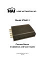
Model 87A00-1
Camera Server
Installation and User Guide
Document Number 87I00-1 Rev. A
July, 2008
DISCLAIMER
•
While every effort has been made to ensure that the information contained in this guide is accurate
and complete, no liability can be accepted for any errors or omissions.
•
HAI reserves the right to change the specifications of the hardware and software described herein
at any time without prior notice.
•
No part of this guide may be reproduced, transmitted, transcribed, stored in a retrieval system, or
translated into any language in any form, by any means, without prior written permission of HAI.
•
HAI makes no warranties for damages resulting from corrupted or lost data due to mistaken
operation or malfunction of the Camera Server recording functions, the software, personal
computers, peripheral devices, or unapproved/unsupported devices.
SAFETY PRECAUTIONS
Users are strongly advised to adhere to the directions and recommendations offered in this manual.
Failure to do so may result in problems during operation.
•
Make sure the correct voltage is being supplied before turning the power on.
•
Do not install with the power turned on. Doing so may cause an electric shock.
•
Do not install in a very humid environment. Doing so may cause an electric shock.
•
Do not install in an area exposed to sunlight or heat. Doing so may cause deformation or
damage.
•
Do not remove the product cover. Doing so may expose you to a hazard like electric shock.
•
Do not use in areas containing flammable materials like propane gas and gasoline or in areas that
generate dust. Doing so may cause an explosion or fire.
•
Do not dismantle, repair, or modify the product. Doing so may cause damage or an electric shock.
Refer all servicing to qualified personnel.
•
Do not use water, thinner, or organic solvent for cleaning the product exterior. Doing so may
cause damage or an electric shock. Use a dry cloth instead and turn off the power before
cleaning.
FCC NOTICE
This device complies with Part 15 of the FCC Rules.
conditions;
Operation is subject to the following two
1. This device may not cause harmful interference, and
2. This device must accept any interference received, including interference that may cause undesired
operation.
Note: This equipment has been tested and found to comply with the limits for Class B digital devices,
pursuant to Part 15 of the FCC rules. These limits are designed to provide reasonable protection
against harmful interference in a residential installation. This equipment generates, uses and can
radiate radio frequency energy and, if not installed and used in accordance with the instructions, may
cause harmful interference to radio communications. However, there is no guarantee that interference
will not occur in a particular installation. If this equipment does cause harmful interference to radio or
television reception, which can be determined by turning the equipment off and on, the user is
encouraged to try to correct the interference by one or more of the following measures:
•
•
•
•
Reorient or relocate the receiving antenna.
Increase the separation between the equipment and receiver.
Connect the equipment into an outlet on a circuit different from that to which the receiver is
connected.
Consult the dealer or an experience radio/TV technician for help.
Do not make any changes or modifications to the equipment unless otherwise specified in the manual.
If such changes or modifications should be made, you could be required to stop operation of the
equipment.
Home Automation, Inc.
4330 Michoud Blvd.
New Orleans, LA 70129
Tel: (504) 736-9810
The Privacy act of 1974 (5 U.S.C. § 552a)
Please note that the HAI Camera Server is intended for monitoring and surveillance use and should
never be used in a manner that invades other people’s privacy or contravenes international or domestic
privacy act and its regulations. Please be advised that in certain cases the recording of individuals,
private properties, or commercial properties by means of camera or other devices may contravene legal
rights of such individuals even if the images were recorded for personal use.
Table of Contents
1. Introduction ·········································································································································1
1.1. Model 87A00-1 Camera Server··································································································1
1.1.1. About the Camera Server ·································································································1
1.1.2. Main Features···················································································································1
1.2. Package Contents ······················································································································2
1.3. Factory Default Settings ·············································································································2
2. Operation ·············································································································································3
2.1. Front Panel·································································································································3
2.2. Rear Panel ·································································································································4
3. Web Interface ······································································································································9
3.1. Accessing the Web Interface······································································································9
User Login ···································································································································9
3.2. ActiveX Installation ···················································································································· 11
4. Main Page Configuration··················································································································12
4.1. Single View································································································································12
4.2. Multi View ··································································································································14
4.3. Setup ·········································································································································14
5. Setup Configuration ·························································································································15
5.1. Video Setup·······························································································································16
5.1.1. Video Settings··················································································································16
5.1.2. OSD Settings ···················································································································18
5.1.3. Advanced ·························································································································20
5.2. Audio Setup ······························································································································21
5.2.1. Audio Input Settings·········································································································21
5.2.2. Audio Output Settings ······································································································22
5.3. Network Setup···························································································································23
5.3.1. General Settings ··············································································································23
5.3.2. QoS Settings····················································································································24
5.3.3. Multicast Settings·············································································································25
5.3.4. DDNS Settings·················································································································26
5.3.5. Advanced Settings ···········································································································27
5.4. Event Setup·······························································································································28
5.4.1. Event Server Settings ······································································································28
5.4.1.1. SMTP Server Settings ··································································································29
5.4.1.2. FTP Server Settings······································································································30
5.4.1.3. TCP Server Settings ·····································································································31
5.4.2. Motion Detection Settings································································································32
5.4.3. Event Settings·················································································································33
5.5. Record Setup ···························································································································37
5.5.1. Recording on USB Flash Drive························································································37
5.5.2. Recording on FTP server·································································································40
5.5.3. Playback the recoded data on the USB device ·······························································41
5.6. System Setup ···························································································································42
5.6.1. System Date ····················································································································42
5.6.2. System Update ················································································································43
5.6.3. User Management ···········································································································44
5.6.4. PTZ Protocol····················································································································45
5.6.5. System Information··········································································································46
5.6.6. Reboot ·····························································································································47
5.7. IO Setup ···································································································································48
5.7.1. Serial Port Setting············································································································48
5.7.2. DI/DO Setting···················································································································49
5.7.3. PTZ ··································································································································50
5.7.4. External Video out Setting ·······························································································51
6. Resetting the Camera Server···········································································································52
6.1. Rebooting ·································································································································52
6.2. Reset to Factory Default···········································································································52
1. Introduction
1.1. Model 87A00-1 Camera Server
The 87A00-1 Camera Server is a device that transmits video and audio data via network in real-time.
The server converts the analog video signals and audio signals into digital data and compresses them
for on-line transmission. Cameras can then be viewed at home or over the Internet on a PC,
OmniTouch 5.7e, OmniTouch 10p, or handheld mobile device, such as PDA, Smartphone, or other
device running Windows® Mobile operating system, using HAI Snap-Link Mobile (1120M) or HAI WL3
(1112). Additionally, these cameras can be viewed on an iPhoneTM when HAI WL3 is used.
Since the server has a built-in web server and network interface, it may not require additional hardware,
software, or programming (besides configuring IP address) to view live video transmissions. After
connecting all the cameras to the Camera Server and configuring its IP address, the Camera Server
can be accessed from anywhere with an Internet connection.
1.1.1. About the Camera Server
The 87A00-1 Camera Server is a 4-channel Camera Server that transmits video in high resolution with
bi-directional audio in real-time via the network. The 87A00-1 supports various network environments
such as high-speed Internet, cable, DSL, LAN, or WAN.
The 87A00-1 Camera Server provides high quality MJPEG encoding at D1 in real time and deinterlacing by the hardware.
The 87A00-1 Camera Server provides the high-performance interactive two-way audio.
1.1.2. Main Features
The 87A00-1 is designed for various applications, such as viewing cameras on an OmniTouch 5.7e,
OmniTouch 10p, or handheld mobile device, remote monitoring, and Internet broadcasting with the user
friendly interface.
Interface to External Equipment
The 87A00-1 Camera Server supports pan/tilt/zoom camera devices, alarm sensors, as well as
other security equipment to customize the monitoring system.
Interactive Audio
In addition to the real-time motion picture and audio transmission, the 87A00-1 provides an
interactive audio transmission function. To provide more precise information at the location, the
87A00-1 Camera Server allows users to hear audio and to watch video images simultaneously
from the remote location where the 87A00-1 server is installed.
1
1.2. Package Contents
Before installing the Camera Server, please make sure that the following items are included in the box:
1.
2.
3.
4.
5.
6.
Camera Server
12VDC Power Adapter with Power Cord
2 Terminal Block
2 Audio Cables
Mounting Hardware
Software Utility and Manual CD
1.3. Factory Default Settings
Factory default settings are as follows:
IP address: 192.168.xx.yy
Mask: 255.255.0.0
Gateway: 192.168.0.1
User ID: root
Password: pass
The last two bytes of the MAC address represents the “xx” and “yy” for the default IP address of the
Camera Server. The last two bytes must be converted from hexadecimal to a decimal number.
After installation, the default IP address can be changed using one of the following methods:
¾ Using the built-in web interface.
¾ Using the “IPAdminTool” Software Utility included on the Software Utilities and Manual CD.
2
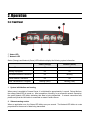
2. Operation
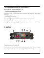
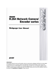
2.4. Front Panel
⑦
⑥
②
①
③
⑤
④
① Status LED
② Network LED
Status (Orange) and Network (Green) LED indicators display the following system information:
Status (Orange)
Network (Green)
Power Off
Off
Off
Booting in progress
On
Off
Successful Network Connection
On
Blinking
Failed Network Connection
On
Off
Blinking (Slow)
Blinking (Fast)
Data Transmission in Progress
1. System initialization and booting
When power is supplied to Camera Server, it is initialized for approximately 1 second. During this time,
the orange Status LED is turned on. After completion of booting, for a successful network connection,
the green Network LED blinks indicating that data is being transmitted. If network connection fails,
please verify that the LAN cable is connected or restart Camera Server.
2. Video streaming service
When an application runs, the Status LED blinks once per second. The Network LED blinks at a rate
proportional to the amount of data being transmitted.
3
③ and ④ Video Input BNC Connectors (Vin 1, Vin 2, Vin 3 and Vin 4)
Used for video inputs. Video input type: NTSC or PAL
⑤ Termination Resistor DIP Switch (75Ω ON)
A switch to turn On/Off a 75Ω termination resistor is provided for each video input. Factory default
setting is ON.
⑥ Video Output BNC Connector
Vout is used to display quad or single channel composite output to an external monitor.
⑦ Reset Switch (Reset)
The Reset Switch is used for restarting the Camera Server or resetting the Camera Server to Factory
Default (FD). Refer to Factory Default Settings for detailed procedures.
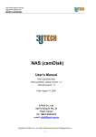
2.5. Rear Panel
③
⑤
⑨
①
②
④
⑦
⑧
⑥
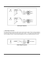
① Audio Input Jack (Ain 1,2 and Ain 3,4)
The Camera Server has mono audio input channels using stereo audio sockets. Therefore, a special
cable is needed to connect audio devices. See the Audio Input Connector diagram.
4
Audio Input Connector
② Audio Output Jack (Aout)
The Camera Server has one mono audio output using the stereo socket. Even if a stereo speaker is
connected, both sides will have the same sound (mono output). The Camera Server audio output is
very low-wattage, therefore it requires amplified speakers (do not use headphone/earphone directly).
Audio Output Connector
5
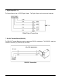
③ Digital Input (DI 1-4)
The Camera Server has 4 Digital Inputs as shown. Each input can be connected either a voltage type
sensor or relay type sensor (dry contact).
Do not use voltage and relay type sensors together.
Voltage Type Digital Input Connections
Relay Type Digital Input Connections
6
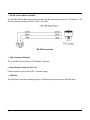
④ Digital Output (DO 1-4)
The Camera Server has 4 12VDC Digital Outputs. The Digital Outputs can be connected as shown:
Digital Output Connections
⑤ RS-232C Terminal Blocks (RS-232C)
The RS-232C Terminal Blocks are used to connect an RS-232 serial device. The RS-232C serial port
consists of Transmit (Tx), Receive (Rx), and GND.
RS-232C Connection
7
⑥ RS-485 Terminal Blocks (RS-485)
The RS-485 Terminal Blocks are used to connect RS-485 serial devices such as PTZ cameras. The
RS-485 serial port consists of DATA+, DATA-, and GND.
RS-485 Connection
⑦ LAN Connector (Ethernet)
This is a RJ45 LAN connector for 10/100 Base-T Ethernet.
⑧ Power Adaptor Connector (DC 12V)
Power connector input for the 12VDC, 3A power supply.
⑨ USB Port
This USB port is used for recording images to a USB storage device such as a USB flash drive.
8
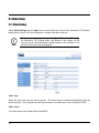
3. Web Interface
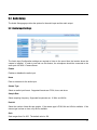
3.1. Accessing the Web Interface
To access the web interface of the HAI Camera Server, open Internet Explorer and enter the IP
address of the 87A00-1 into the address bar.
Enter the IP address in the address bar of the browser as shown below:
http://(IP address)
For example:
http://192.168.1.2
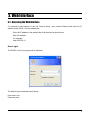
User Login
The 87A00-1 user’s log in page will be displayed.
The default login credentials are as follows:
User name: root
Password: pass
9
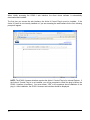
When initially accessing the 87A00-1 web interface, the client viewer software is automatically
downloaded and installed.
The first time you access the web interface, the Active-X Control Plug-In must be installed. If the
Active-X Control is not currently installed or if you are accessing the web interface for the first, following
prompt will appear.
NOTE: The 87A00-1 browser interface requires the Active-X Control Plug-In for Internet Explorer. If
the Active-X Control Plug-In is not installed, you will be prompted to install the plug-in before the
87A00-1 interface is launched. You must answer “YES” to the questions about installation of the
plug-in. After installation, the 87A00-1 browser web interface should be displayed.
10
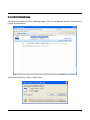
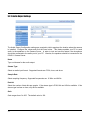
3.2. ActiveX Installation
You will need to install ActiveX for displaying images. Click “Pop-up Blocked” and then “Install Active X
Control” as shown below.
At the Security Warning, click the “Install” button.
11
4. Main Page Configuration
4.1. Single View
When the installation of the client program is complete and your login is accepted, the 87A00-1 Viewer
is automatically connected and begins displaying video.
SingleView shows only one camera on a page.
Video 1 is set as the default channel and other channels are chosen from the drop-down combo box.
12
•
PLAY: Play the current camera.
•
STOP: Stop the current camera.
•
SNAPSHOT: Save a snapshot of current video image.
Note: The file is saved in \My Documents\Snapshot folder
•
Full Screen: Stretches the camera image to fill the full screen.
•
PTZ: Virtual PTZ control keyboard is displayed. This is used to control PTZ cameras.
•
Motion View: When motion detection is set on the Event menu, you can see the detection
status on the current image screen.
•
OSD View: Shows the current image information, RTSP address, Channel number, FPS, Frame
type, Frame Size, and Date and time on the image view screen.
•
Audio Enable – Allows you to listen to the audio sound. To enable this function, the audio
connection cable should be connected to IP Products from the video source.
•
MIC Enable – Allows you to send the audio through a microphone from your PC to the site
where the camera is installed. The audio input from the microphone will be transmitted via
network.
13
4.2. Multi View
MultiView displays all 4 cameras on one page. Individual Play, Stop, and Snapshot button are
available for each camera in MultiView mode.
4.3. Setup
Setup allows users to completely configure the Camera Server. See
5. Setup Configuration for an explanation of each option and how to set and change the values.
14
5. Setup Configuration
The Setup Configuration pages allow you to completely configure the Camera Server.
Click Setup on the main page of web interface. On the left side of the main page, you can see the
following categories:
Video
¾ Video Setting
¾ OSD Setting
¾ Advanced
Audio
¾ Audio Input
¾ Audio Output
Network
¾ General
¾ QOS Setting
¾ Multicast
¾ DDNS
¾ Advanced
Event
¾ Motion
¾ Event
¾ Event Server
Record
¾ Record
¾ USB Data
System
¾ System Data
¾ System Update
¾ User Management
¾ PTZ control
¾ System Information
¾ Reboot
IO
¾
¾
¾
¾
Serial Prot Setting
DI/DO
PTZ
External Video Out
15
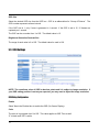
5.1. Video Setup
5.1.1. Video Settings
Select Video Settings from the Video menu to select the Video Type, Codec, Resolution, FPS, Bitrate
Mode, Bitrate, Quant, GOP size, Brightness, Contrast, Saturation, and Hue.
i
Note
Whenever a camera is viewed on an OmniTouch 5.7e or OmniTouch 10p,
the Resolution, FPS, Bitrate Mode, and Bitrate of the camera on the
Camera Server will automatically change based on the settings of the
camera in the OmniTouch touchscreen.
Video Type
Select the video type from the Video Type box. The video format is detected automatically when the
device boots up. If you change the video type manually to a certain type, it will only affect the FPS.
Video Codec
The video codec in the Camera Server is MJPEG.
16
Resolution
Select the desired resolution from the Resolution box. Refer to the table below.
D1
VGA
QVGA
4CIF
2CIF
CIF
QCIF
NTSC
720x480
640x480
320x240
704x480
704x240
352x240
176x112
PAL
720x576
640x480
320x240
704x576
704x288
352x288
176x144
FPS (Frames per Second)
Select the desired FPS from the FPS box. This value represents the number of encoded frames you
want to get per 1 second.
Video Format
NTSC
PAL
Available frame rate
30, 15, 7.5, 10, 6, 3.75, 2, 1
25, 12.5, 8, 6.25, 5, 4, 3, 1
Bitrate Mode
Select the desired bitrate mode from the Bitrate Mode box.
The following bitrates are supported: CBR, VBR and HVBR. The default mode is CBR. If you set as
HVBR, both Bitrate and Quant values can be set.
Bitrate
Enter a bitrate in the Bitrate box. The default value 1.5Mbps. Bitrate is only adjustable when the bitrate
mode is CBR or HVBR. The range is from 32 Kbps to 10Mbps.
i
Note
Since the maximum bitrate is 10Mbps, you should distribute the bitrate
between the number of installed cameras within 10 Mbps.
Quant
Enter a quant value in the Quant box. The default value is 128. Quant is only available when the
Bitrate mode is VBR. The range is from 0 to 255. The Quant value is related to the image quality of
VBR setting. The lower value makes high quality images.
17
GOP Size
Select the desired GOP size from the GOP box. GOP is an abbreviation for “Group of Pictures”. The
GOP number represents a frame interval.
If the GOP size is 1, only I frame is generated in 1 second. If the GOP is set to 15, 15 frames are
captured per 1 second.
The GOP can be a number from 1 to 255. The default value is 15.
Brightness/Saturation/Contrast/Hue
The range of each value is 0 to 255. The default value for each is 128.
5.1.2. OSD Settings
NOTE: The coordinate value of OSD is absolute points and it is subject to image resolution. If
your OSD setting position is not as you expected, you may need to adjust the image resolution.
OSD String Configuration
Enable
Select Yes in the Enabled box to enable the OSD (On Screen Display).
Color
The color is in grayscale from 0 to 255. This value applies to OSD Time as well.
“0” is black and “255" is white.
18
String
Enter the maximum length of OSD text (ASCII character string).
X/Y
Type the location of the string by entering the X and Y coordinates.
For example, if the coordinates are (0, 0), the time stamp will be shown on the top left of image.
Input range of coordinate value:
X: 0 - 44
Y: 0 - 29
OSD Time configuration
i
Note
The OSD time setting is available only on the 1st camera and the other
cameras do not support the Time OSD setting.
The OSD time is refreshed every 1 second.
Enable
Select Yes in the Enabled box to enable the Time OSD.
Format
The time information is synchronized with a NTP server (this can be configured under System in the
System Data menu). Even though the box is open, it’s not available to correct the time manually.
X/Y
Type the location of the string by entering the X and Y coordinates.
For example, if the coordinates are (0, 0), the time stamp will be shown on the top left of image.
Input range of coordinate value:
X: 0 - 32
Y: 0 - 29
19
5.1.3. Advanced
Horizontal delay
A higher setting moves the image towards the left. The setting ranges from 32 to -32
Vertical delay
A higher setting moves the image towards the top. The setting ranges from 4 to -4
Copying an image to shared memory
This setting allows the Camera Server make the best use of the source.
De-interlace Mode
Select Yes to enable de-interlacing. Select No to disable de-interlacing.
20
5.2. Audio Setup
The Audio Setup page provides the options for the audio input and the audio output.
5.2.1. Audio Input Settings
The Audio Input Configuration settings are required to listen to the sound from the location where the
camera is installed. In order to test and use this feature, the microphone should be connected to the
audio port of 87A00-1 Camera Server.
Enable
Enables or disables the audio input.
Name
Enter a nickname for the audio input.
Stream Type
Select an audio input format. Supported formats are: PCM, uLaw, and aLaw.
Sample Rate
Select sampling frequency. Supported frequencies are: 16 KHz. and 8 KHz.
Data bit
Select the number of data bits per sample. If the stream type is PCM, 8bit and 16bit is available. If the
stream type is aLaw or uLaw, only 8bit is available.
Gain
Gain ranges from 0 to 255. The default value is 128.
21
5.2.2. Audio Output Settings
The Audio Output Configuration settings are required to talk to people at the location where the camera
is installed. Configure the values and click the Save button. This feature enables your PC to send
audio to the speakers on the Camera Server. In order to test and use this feature, the microphone
should be connected to the audio port of your PC. Likewise, the speakers should be connected to the
87A00-1 Camera Server.
Name
Type a nickname for the audio output.
Stream Type
Select an audio input format. Supported formats are: PCM, uLaw, and aLaw.
Sample Rate
Select sampling frequency. Supported frequencies are: 16 KHz. and 8 KHz.
Data bit
Select the number of data bits per sample. If the stream type is PCM, 8bit and 16bit is available. If the
stream type is aLaw or uLaw, only 8bit is available.
Gain
Gain ranges from 0 to 255. The default value is 128.
22
5.3. Network Setup
The Network Setup page is used to configure various network and operational settings of the 87A00-1
Camera Server.
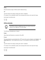
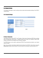
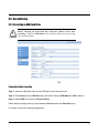
5.3.1. General Settings
IP Address Configuration
If the Network mode is set to DHCP, the IP address, Subnet mask, Gateway and DNS Server settings
will be received from a DHCP server. If Network mode is set to Static, the IP address, Subnet mask,
Gateway, and DNS Server settings must be manually configured.
The PPPoE feature can be used by entering the PPPoE ID and password provided by your Internet
Service Provider.
Note: You can obtain and modify the default network settings of the 87A00-1 Camera Server using the
IPAdminTool Software Utility (IPAdminTool.exe) included on the Software Utilities and Manual CD.
23
5.3.2. QoS Settings
The 87A00-1 Camera Server uses a DSCP model for implementing QoS. Additionally, video, audio,
and event classes are available for that.
What is DSCP?
It is short for Differential Services Code Point, which is a field in the header of IP Packets for packet
classification purposes.
Video DSCP:
DSCP of video packet
Audio DSCP:
DSCP of audio packet
Event DSCP:
DSCP of event packet
DHCP values should be specified in a decimal number converted from original 6 bit binary digit. The
default value is “0”, which means 000000 for DSCP value. To set the device available of supporting
Expedited Forwarding, the recommended value for DSCP is 46 (101110).
24
5.3.3. Multicast Settings
This page provides the multicast configuration of each channel. The addresses are a group of address
which is required to receive data from the router.
The values in the boxes are default. You can set the values according to your network requirement.
The Camera Server supports only RTSP multicast (UDP/RTP Multicast is not supported).
25
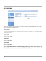
5.3.4. DDNS Settings
For DDNS configuration setup, you must first create a DDNS account with dyndns.com.
Server Enable: Select YES to use DDNS.
Server Type : DynDNS (no other settings allowed at this time).
Address: www.dyndns.com (no other servers allowed at this time).
User ID: your user ID created at the Dyndns.com.
User PW: your password registered at the Dyndns.com (case-sensitive).
DNS name: your dynamic domain host server name.
Update time: Specify how often the dynamic domain server is updated (unit: minutes).
Port: Default value is -1. This means the DDNS feature is disabled as a default.
If you use DDNS, you can type the required port number for DDNS.
z IP Type (Real/Local):
Real represent the device’s public IP seen by DDNS server.
Local represents the private IP address of device.
z
z
z
z
z
z
z
z
i
Note
26
Note: Only one dynamic host name is saved.
5.3.5. Advanced Settings
RTSP Port
This is the port number for first channel for RTSP. If a device has more than one channel, the port
number of next channel succeeds the port number of the first channel.
For example, if the port number of first channel is 554, the second channel would be 555.
Web Port
This is the port number for HTTP.
User RTST Port
This setting is required ONLY when you have set ‘port forwarding’ on router device. If your network
does not require port forwarding, just leave the “User RTSP Port” value empty or set it to the same
value as the RTSP Port.
When “port forwarding” is done on a network router, the ActiveX viewer on the client side can’t find the
port number and ActiveX image may not be seen. Because ActiveX is operated only on a client and
not able to get the network setting values.
27
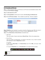
5.4. Event Setup
This manual assumes that Motion Detection is an event action trigger. So, consider this carefully and
follow the setting step as the order below. If your event factor is not Motion Detection, you can just skip
Step2: Motion setting.
Step 1: Event Server setting
Step 2: Motion setting
Step 3: Event setting (related to the event setting and motion detection setting you configure)
The event server supports SMTP, TCP, and FTP servers.
Select Motion from the Event menu. Select the Event Server tab.
To apply this event function, configure the Event server first, and then enter the Motion settings.
Before configuring the event server, the following should be configured first:
• Go to the Video -> Advanced menu on the left of this page and turn
on Copying a image to shared memory by setting it to Yes
Caution
!
5.4.1. Event Server Settings
28
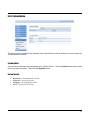
5.4.1.1. SMTP Server Settings
To register the SMTP server, click on the SMTP in the box and press the Modify button on the right.
FromEmail
Enter the email address of a sender.
MailServer1
Enter the SMTP server address.
MailServer1 Port
Enter the SMTP server port number (default port number 25).
ID
Enter the ID of the sender’s email account.
Password
Enter the password of the sender’s mail account (case-sensitive).
29
5.4.1.2. FTP Server Settings
To register the FTP server, press the Add FTP button.
Name
Enter a descriptive name for the FTP server.
Address
Enter the IP address or domain name of FTP server
NOTE: To use domain name of FTP server, make sure if the DNS setting is enabled.
Port
Enter the port number of FTP server (0 – 65535).
User ID / User PW
Enter the FTP Server log-in ID and Password (case-sensitive).
Upload path
Type the path of uploaded files
For example: /home/
Timeout
Enter the timeout value for FTP connection and data transfer (Unit: μs).
The default value is set as 100000 (0.1 sec).
30
5.4.1.3. TCP Server Settings
To add a TCP server, press Add TCP button.
Name
Enter a descriptive name for the TCP server.
Address
Enter the IP address of TCP server.
Port
Enter the port number of TCP server (0 – 65535).
31
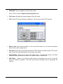
5.4.2. Motion Detection Settings
After all of the settings have been entered for the Event Server, select the Motion tab to enter the
settings for the motion detection functions.
How to register Motion Detection
Step 1: Select a camera from the Image Source combo box and then press Play button.
Step 2: Select a layer from the Layer ID combo box.
Step 3: Check the Motion Enable checkbox.
Step 3: Right-click anywhere on the camera display to make an Area rectangle.
Step 4: Adjust the size of the Area rectangle by dragging the edges.
Step 5: Press SAVE and then RUN to test the motion detection settings.
You can set up to 3 layers. Each layer can have up to 8 areas.
The Object size and Sensitivity values of each Layer applies to all of the Areas on that Layer.
•
•
Sensitivity – sensitivity of each macro block (16 x 16 pixels).
ObjectSize – proportion of the exceeded Sensitivity of macro block in the respective Area.
Sensitivity and ObjectSize range from 1 to 255. A lower value means the higher sensitivity.
32
5.4.3. Event Settings
To register an Event, follow Steps 1-3 below.
Step 1
1. Click Add to create an Event.
Name
Enter a descriptive name for the event
Event Type
•
•
Software – device boots, motion detection, video losses, etc.
Hardware – Digital Input activation (such as sensor).
Hardware Mode
If the event type is a Hardware type, use the following convention:
Nnnn = where n = {x, 1}
x = do not trigger
1 = trigger on activation
For example: “1xxx” means to trigger when first Digital Input is activated.
“1xx1” means to trigger when the first and fourth Digital Input are activated.
33
Software Mode
Select one of the following event modes: Motion Detection, Video Loss, and Boot.
Motion Detection: Event occurs when the motion is detected.
Video Loss: Event occurs when there is loss of video (disconnected or connected).
BOOT: Event occurs when the Camera Server is rebooted.
MD
Enable only if software mode is set to Motion Detection.
To set the MD value, press the View CGI button on the Motion setting page to see the MD values.
For example, if MD is set to “M0,” it means motion detection is triggered from Layer1. In the same
manner, M1 means Layer 2 and M2 means Layer 3.
Video Loss
Enter camera number for triggering the event.
Image Number
Enter camera number to connect with event
Trigger Interval
1 second (’00:00:01’) is set as the default value. Assuming the value is ’00:00:05,’ even if the event
happens several times for 5 sec, the Camera Server will trigger only once per 5 seconds.
34
Step 2
1. Click on the Event tab on the left menu and then select the event that you created in the box.
2. Click the Modify button.
3. Click the Action button.
Step 3
1. Select the proper server from the Server list and set the respective values.
Event Action
The actions that are created are listed. Select an Event Action from the list.
Server
Select the appropriate server from the list.
TCP, SMTP, FTP, DO and USB recording server are available. If the desired server is not shown in
this list, registration of the server was not successful. Go back to the Event Server Setting section
and follow the instruction for adding a server.
35
Message
Enter an email message that will be sent.
EmailTo
Enter an email address of the recipient.
Subject
Enter the subject of the email.
ImagePerMail
Enter “1” to send a captured image with the email message. Otherwise, enter “0” for no image.
When you set the values on the Event Action Configuration page, depending on the Server, the
required values may be different.
•
•
•
•
•
36
SMTP: Set all of the values
FTP: Only Server and Message are required
TCP: Only Server and Message are required
DO: No values are required
USB recording: No values are required
5.5. Record Setup
5.5.1. Recording on USB Flash Drive
Before removing the USB flash drive from the Camera Server after
recording…change the USB Mount value to No first. Otherwise, the recording
may
not work properly.
Caution
!
Preparation before recording
Step 1: Insert the USB flash drive into the USB port on the Camera Server.
Step 2: Click Record from the Record menu and set the value of USB Mount to YES as above.
Step 3: Select USB for the value of Record Device.
Select which recording mode you want between Passive mode and Schedule mode.
For details, refer to the following explanations.
37
How to record video NOW (Passive mode)
Step 1: Set the Record Enable as YES
Step 2: Set the Record Mode as Passive
Step 3: Enter the Port Number and Record Recycle
•
Port number:
Used for playback. 2100 is set as the default.
•
Record Recycle:
Rotate lets the new files overwrite existing files when USB memory is full.
None lets the recording stop if the USB memory is full.
Step 4: PostTime is set in seconds. If you want to record for 30 minutes, type 1800 for the value of
PostTime. The recording will continue for 30 minutes on when the Record button is presses.
Step 5: Set the Skip Frame and Record Frame as described below:
•
Skip Frame:
This is the number of frames to skip between Record Frame. Refer to the examples below.
•
Record Frame
This is the number of recorded frames. For example, if the value is 0, only 1 frame is recorded
after skipping the number of Skip Frame set above.
For example:
If “149” is set for Skip Frame, “0” for Record Frame, and “30” for FPS, you will get 1 frame
every 5 seconds.
If “5” is set for Skip Frame and “1” for Record Frame, you will get the frames as below.
F#
0
1
2
3
4
5
6
Recording Frame
레
Skip Frame
Step 6: Click the Record button to start the recording.
38
7
8
9
10
11
12
13
How to record on SCHEDULE (Schedule mode)
If you want to record the video according to the specific date and time, follow the instructions below.
Step 1: Follow the same steps of How to record Video NOW except for Step 2.
Step 2: Set the Record Mode to Schedule.
Step 3: Set Record Weekdays, Start Time and End Time as described below:
•
Record Weekdays
Assign days for recording. The first digit corresponds to Sunday and last digit corresponds to
Saturday. For example, if 0111110 is set, the recording runs only from Monday to Friday.
•
Start Time
Enter the time to start recording (time format - 00:00).
•
End Time
Enter the time to end recording (time format - 00:00).
Step 4: Click the Record button to start the recording.
39
5.5.2. Recording on FTP server
Step 1: In order to record the video on an FTP server, the FTP server must be added in advance. Refer
to section 5.4.1.2 FTP Server Settings.
Step 2: Set Record Device as FTP.
Step 3: Set Record Mode as desired. Refer to section 4.5.1 Recording on USB flash drive.
Step 4: Set the FTP Server Number. This is available only after Step 1 has been completed.
Step 5: PostTime is set in seconds. If you want to record for 30 minutes, type 1800 for the value of
PostTime. The recording will continue for 30 minutes on when the Record button is presses.
Step 6: Set the Skip Frame and Record Frame as described below:
•
Skip Frame:
This is the number of frames to skip between Record Frame. Refer to the examples below.
•
Record Frame
This is the number of recorded frames. For example, if the value is 0, only 1 frame is recorded
after skipping the number of Skip Frame set above.
For example:
If “149” is set for Skip Frame, “0” for Record Frame, and “30” for FPS, you will get 1 frame
every 5 seconds.
If “5” is set for Skip Frame and “1” for Record Frame, you will get the frames as below.
F#
Recording Frame
레
Skip Frame
40
0
1
2
3
4
5
6
7
8
9
10
11
12
13
5.5.3. Playback the recoded data on the USB device
If the USB recording steps have been completed, the recording status can be viewed on the USB
Record List page.
•
•
•
Record List: Show the created recording files
Play/Stop: Select a file from the Record List and click Play or Stop to display the control
Delete: Select the file to be removed and then click the Delete button
41
5.6. System Setup
5.6.1. System Date
Device Time
Displays the date and time of Caners Server
Time Zone
Select your time zone
Time Mode
You can select a time mode with 3 options.
42
•
Client Time: Synchronized with your current PC time.
•
NTP Server: Synchronized with a NTP server. By default ‘time.nist.gov’ is the selected server;
however any NTP server can be selected from the list or one can be manually entered.
•
User Setting: The time and date will be manually entered.
5.6.2. System Update
This page is used to update of the software in the Camera Server and to display the current version for
various software modules.
System Update
You can upload firmware files and update your Camera Server. Click the Search button and choose
the file you want to upload. Then click the Upgrade button.
Current Version
•
•
•
•
Bootloader: Current bootloader version
Firmware: Current FW version
Webpage: Current Webpgae version
OCX: Current ActiveX version
43
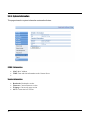
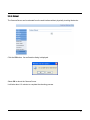
5.6.3. User Management
User Management is used to add user login accounts to the Camera Server.
There are two user types provided by default:
User
root
guest
Password
pass
guest
Security Level
Admin
Guest
Accounts can be created up to 10 including two default users.
•
ID: Up to 32 characters with the combination of alphabets and digits. First character must be an
alphabet (case-sensitive).
•
Password: From 3 to 8 characters with the combination of alphabets and digits (case-sensitive).
How to add a user
1. Click Add.
2. Type User & Password and select Security Level on “User add” dialog.
3. Select Add button on the “User add” dialog.
4. Click Close on the “User add” dialog.
How to delete a user
1. Select a user to delete from the User List.
2. Click Delete.
3. Click OK on confirmation dialog.
4. Click Close on the “Remove user” dialog.
44
How to modify a user
1. Select a user to modify from the User List
2. Click Modify.
2. Modify the password or security level.
3. Select Modify on the “User Modify” dialog.
4. Click Close on the “User Modify” dialog.
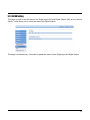
5.6.4. PTZ Protocol
This page shows the list of current PTZ protocols built-in the Camera Server and also allows you to
upload a new PTZ protocol.
How to add PTZ protocol manually
1. Click the Browse button.
2. Choose the required file and click the Upload button.
3. The protocol will be added to the list
Click PTZ from the IO menu to choose the PTZ protocol.
Refer to section 4.7.3 PTZ to learn how to apply the newly added protocol to the Camera Server.
45
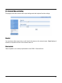
5.6.5. System Information
This page shows the system information as described below:
87A00-1 Information
•
•
•
MAC: MAC Address
TIME: Date and time information on the Camera Server
Version Information
•
•
•
•
46
Bootloader: Bootloader version.
Firmware: Current firmware version
Webpage: Current web page version
OCX: Current ActiveX version
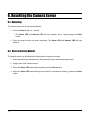
5.6.6. Reboot
The Camera Server can be rebooted from the web interface without physically touching the device.
Click the OK button. As confirmation dialog is displayed.
Select OK to reboot the Camera Server.
It will take about 1-2 minutes to complete the rebooting process.
47
5.7. IO Setup
5.7.1. Serial Port Setting
This page provides the configuration of RS-232C and RS485.
•
•
•
•
48
Baudrate: 9600
Parity: none
Flow Control: none
Stopbit: 1
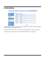
5.7.2. DI/DO Setting
This page is used to see the status of the Digital Inputs (DI) and Digital Outputs (DO) on the Camera
Server. It also allows you to control the state of the Digital Outputs.
This page is refreshed every 3 seconds to update the status of each Digital Input and Digital Output.
49
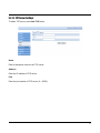
5.7.3. PTZ
This page allows you to select the PTZ Protocol for each camera.
PTZ protocol options are shown in the drop down combo box.
You can choose a protocol for each camera.
1. Check Enable in the check box and choose the desired protocol.
2. Set the Addr and CommPort foe each camera input.
3. Click the Apply button.
PtzDriver
Select the desired protocol from the list.
Addr
Set the Addr value according to the ID set by dip switch on the PTZ camera.
CommPort(0-1)
0 = RS232C
1 = RS485C
50
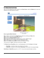
5.7.4. External Video out Setting
This page provides the external video output settings and video loopback function settings.
Video Out
You can choose either single view or multi-view for the stream on the external output. Quad displays 4
channels as a quad multi-view on the external video out.
Video Loopback
Video Loopback is not currently implemented on the 87A00-1 Camera Server.
51
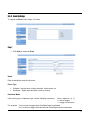
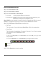
6. Resetting the Camera Server
6.1. Rebooting
The camera server can be rebooted as follows:
1. Press the Reset button for 1 second.
¾ The Status LED and Network LED will blink together, twice. Stop pressing the Reset
button.
2. When the reset function has been completed, The Status LED and Network LED will stop
blinking.
6.2. Reset to Factory Default
The camera server can be initialized to factory default settings as follows:
1. If the Camera Server is powered-up, disconnect the power removing the power input.
2. Apply power to the Camera Server.
3. When the Status LED starts blinking rapidly, press the Reset button.
4. When the Status LED starts blinking slowly (about 5 seconds after booting), release the Reset
button.
52