1
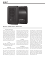
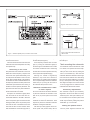
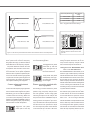
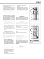
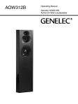
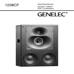
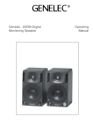
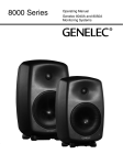
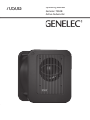
7050B
Operating Manual
Genelec 7050B
Active Subwoofer
Genelec 7050B Active Subwoofer
General description
Genelec 7050B active subwoofer is a
very compact low frequency loudspeaker,
designed to extend the bass reproduction of
Genelec 8020A active loudspeakers in stereo
or surround applications and models 8030A
or 8130A in stereo applications. Adding the
7050B to these loudspeakers creates a compact nearfield monitoring system capable of a
flat frequency response from 25 Hz to 20 kHz
(± 3 dB). The 7050B should not be used
in surround applications with the 8030A or
8130A due to their greater SPL capacity.
Driver
The 7050B contains a single 205 mm (8”)
magnetically shielded low frequency driver,
housed in a Genelec Laminar Spiral EnclosureTM (LSETM) bass reflex cabinet.
Crossover
The crossover contained within the amplifier
has a fixed 85 Hz low pass filter for the five
main channels. However, the signal passing
through the “OUT” connectors is full bandwidth, i.e. not filtered. Because of this, the
“BASS ROLL-OFF” switch (switch 2) on the
main loudspeakers must be switched on to
avoid unwanted overlapping of the frequency
bands between the subwoofer and main loudspeakers. Due to this and the input sensitivity
of the 7050B subwoofer, it can only be used
with Genelec 8020A, 8030A, 8130A, 1029A,
2029A and 2029B active loudspeakers. The
LFE input has a selectable 85/120 Hz low pass
filter and selectable 0/+10 dB input sensitivity.
The overall input sensitivity of the subwoofer
can be reduced from -6 dB to +12 dB for easy
level matching with the main loudspeakers.
Amplifier
The amplifier produces 70 W of output power,
with very low THD and IM distortion. Driver
overload protection and power-on signal
muting is included in the amplifier circuitry.
The amplifier also incorporates thermal overload and short circuit protection.
Installation
The subwoofer is supplied with a mains cable
and this operating manual. Once unpacked
inspect the subwoofer to ensure that it has
not been damaged in transport. Check that
the mains voltage marking on the back panel
matches your local mains voltage. Ensure
that both the subwoofer and the main loudspeakers are switched off before making any
connections.
Audio connections are made with balanced XLR cables. The 7050B has IN/OUT
connector pairs for five main channels and
a dedicated LFE input connector for the LFE
channel. Connect the signal cables from your
source to the female XLR "IN" connectors on
the lower connector row. Next connect XLR
cables from the corresponding "OUT" male
XLR connectors on the upper row to the
input connectors of each main loudspeaker.
Turn the volume control knob on all main
loudspeakers fully clockwise and switch the
"BASS ROLL-OFF" dip switch (switch 2) on
all main loudspeakers to "ON". This switch
actuates an 85 Hz highpass filter on the main
loudspeakers matching them to the main
channel lowpass filter of the subwoofer.
Alternatively, you can connect a stereo
pair of loudspeakers by routing the signal
cables from the source to the input connectors of the main loudspeakers and an another
pair of cables from the main loudspeakers'
output connectors to the "IN" connectors on
the 7050B. In this configuration the volume
controls on the main loudspeakers affect the
playback level of the 7050B, too. The "BASS
ROLL-OFF" switch on the main loudspeakers
must be switched to "ON".
Use the "LFE IN" connector for the LFE or
Figure 2. XLR to RCA connector for
unbalanced operation.
Figure 1. 7050B's amplifier panel, connectors and controls.
.1 output channel of a 5.1-channel discrete
surround sound source.
Once all connections have been made, the
subwoofer and main loudspeakers are ready
to be powered up.
Positioning in the room
The placement of the subwoofer in the room
affects the overall frequency response and
sound level of the system dramatically, as at
low frequencies the effects of the room are
strong. Even a slight change in the subwoofer's location can make a marked difference in
the frequency balance and often patient and
methodical experimentation and testing is
needed to find the optimum placement. The
placement will affect the phase difference
between the main loudspeakers and the subwoofer and the bass roll-off rate.
First place the subwoofer slightly offset
from the center of the front wall. The recommended distance to the wall is less than
60 cm / 24" measured from the subwoofer's
driver. This position gives increased acoustic
loading (and SPL) due to the proximity of the
front wall and floor. Cancellations from the
front wall and floor are also avoided. Front
wall cancellation for the 85 Hz high pass filtered main speakers can be eliminated by
placing them at least 110 cm / 43" away from
the front wall (see Figure 2).
If the frequency balance does not seem
right, try moving the subwoofer slightly to
the left or right so that different room modes
are excited at different levels. Positioning
the subwoofer close to a corner will boost
the bass level at lower frequencies and may
cause asymmetrical spatial imaging.
Although the 7050B is magnetically
shielded, it may cause colour distortion if
placed near to very sensitive video loudspeakers or computer displays. Move the subwoofer
further away or try turning the driver side of
the subwoofer away from the screen.
Minimum clearances to walls
or other objects
Do not cover the driver side of the subwoofer
or place the subwoofer so that there is less
than 10 cm (4") of free space in front of the
grille.
Make sure that the space underneath the
subwoofer is clear from obstructions. Thick
carpets may block the ventilation clearance
needed for cooling the electronics.
The reflex port side (opposite of the connector panel side) should always have a
clearance of at least 7,5 centimeters (3") to
Figure 3. Recommended distances to
the front wall
any objects to ensure proper functioning of
the reflex port.
Flush mounting the subwoofer
If the subwoofer is flush mounted into a wall
or a cabinet, it is important to ensure amplifier cooling and unrestricted airflow from the
reflex port. This can be done by making the
recess 7,5 centimeters (3") wider than the
subwoofer. Place the subwoofer into the right
end of the recess with the driver side facing
the room. This leaves sufficient 7,5 centimeters (3") of free space on the reflex port side.
The height and depth of the recess should
not be any bigger than is needed to fit the
subwoofer flush with the wall surface.
Sensitivity adjustment
The subwoofer requires input sensitivity
alignment to the source to obtain a correctly
balanced system. The input sensitivity control is located on the connector panel of the
subwoofer. An input voltage of -6 dBu with a
-6 dBu input sensitivity setting will produce
100 dB SPL @ 1 m in free field.
Setting the phase control
Incorrect phase alignment between the
main loudspeakers and subwoofer causes
Phase Difference: 90°
Phase Difference: 0°
85 Hz
Subwoofer placement
Bass Roll-Off
setting
Near to a wall
-2 dB
In a corner
-6 dB
Flush mounted
-2 dB
Table 1. Suggested Bass Roll-Off settings
85 Hz
Phase Difference: 270°
Phase Difference: 180°
85 Hz
85 Hz
Figure 4. The effect of phase difference between the subwoofer and the main loudspeakers
a drop in the frequency response of the
whole system at the crossover frequency.
The graphs above (Fig. 4) show the effect of
phase difference to the frequency response.
The phase difference between the main
loudspeakers and subwoofer at the listening position is dependent upon the position
of the subwoofer, so the phase adjustment
should be done only after the preferred position is found. Acoustic measuring equipment
is required for accurate system alignment. If
this equipment is not available, the following
coarse phase matching can be applied.
to the position which gives the lowest sound
level at the listening position.
Next toggle the -90° phase
switch (DIP 4) "ON" and
"OFF", and again set it to
the position which gives
the lowest sound level.
Finally, set the -180° phase
switch (DIP 5) to the opposite setting and deactivate
the test signal.
Coarse phase adjustment
method
Phase correction method with
test equipment
Connect an audio frequency signal generator
to the “FRONT CENTER” input of the 7050B
and set it to feed a 85 Hz signal to the system.
Alternatively, you can use a 85 Hz signal fom
a suitable audio test recording. Make sure
The following procedure matches the phase
between the subwoofer and the main loudspeakers using a frequency analyser and a
pink noise generator. Connect a high grade
measuring microphone to the analyser and
feed pink noise into the "CENTER IN" input of
the subwoofer. Position the microphone at the
listening position and adjust the input sensitivity of the subwoofer until frequencies below
and above 85 Hz are reproduced at equal
level. Then adjust the phase control switches
for the maximum dip of at least -6 dB at the
crossover frequency (85 Hz).
you connect (even temporarily) a main loudspeaker to the "FRONT CENTER" output, so
that the test signal is properly reproduced by
both subwoofer and main loudspeaker.
Toggle the -180° phase
switch (DIP 5 from left)
"ON" and "OFF", and set it
Figure 5. Flush mounting the subwoofer.
Note the clearance needed on the reflex
port side.
Change the -180° switch to the opposite
setting. The phase should now be set correctly and the frequency analyser should
show a smooth response around 85 Hz.
Using the LFE Bandwidth and
LFE +10 dB functions
The “LFE BANDWIDTH” switch allows you to
select the upper cutoff frequency of the LFE
channel between 85 and 120 Hz. Limiting the
LFE bandwidth to 85 Hz can be used to simulate the effect of some consumer decoders
that do not replay information above 80 Hz on
the LFE channel when the bass management
is used. Checking the multichannel mix with
this setting on lets you know how it translates
in systems with this limitation.
The 120 Hz LFE bandwidth setting complies with the replay systems of movie theaters and cinemas. 35 mm movie soundtracks
use the LFE channel to reproduce a bandwidth of 20 - 120 Hz through dedicated
subwoofers. In this case the LFE and main
channel bandwidths overlap between 85 and
120 Hz, which may create unwanted acoustical summing if the same signal is present in
both channels. To avoid this, the LFE content
should be kept completely different (de-correlated) from the low frequency content of
the main channels when mixing music and
sound effects for film release.
In Dolby Digital and DTS encoding formats
the LFE channel has to be monitored with
+10 dB gain in relation to the main channels.
The object is to increase the recording headroom of the LFE channel. Consumer and theatrical decoders automatically add +10 dB of
LFE gain to restore the level balance.
The "LFE +10 dB" function on the 7050B
subwoofer is designed to add the +10 dB
gain to the LFE channel in the production
stage, if it is not already done in the output
matrix of the mixing console. The function is
activated by switching the "LFE +10 dB" dip
switch on the subwoofer to "ON". The "LFE
+10 dB" function should not be used in following cases:
• If the +10 dB LFE gain is already
implemented by another device.
• When producing an audio format that
does not require the use of +10 dB
gain on the LFE channel, such as
DVD-Audio (MLP), SACD (DSD) etc.
• When monitoring a decoded Dolby
Digital or DTS soundtrack. The decoder
will automatically provide +10 dB
LFE gain.
Safety considerations
Genelec 7050B subwoofer has been
designed in accordance with international
safety standards. However, to ensure safe
operation and maintain the unit in safe operating condition, the following warnings and
cautions must be observed:
•
•
•
•
•
Servicing and adjustment must only be
performed by qualified service
personnel. The subwoofer cabinet or
electronics unit must not be opened.
Do not use this subwoofer with an
unearthed mains cable or an unearthed
mains connection as this may
compromise electrical safety.
Do not expose the subwoofer to water
or moisture. Do not place any objects
filled with liquid, such as vases on the
subwoofer or near it.
This subwoofer is capable of producing
sound pressure levels in excess of
85 dB, which may cause permanent
hearing damage.
Free flow of air around the subwoofer is
necessary to maintain sufficient cooling.
•
Do not obstruct airflow around the
subwoofer.
Note that the amplifier is not completely
disconnected from the AC mains service
unless the mains power cord is removed
from the amplifier or the mains outlet.
Warning!
This subwoofer is capable of delivering sound
pressure levels in excess of 85 dB, which
may cause permanent hearing damage.
Maintenance
No user serviceable parts are inside the
subwoofer. Any maintenance of the unit must
only be performed by qualified service personnel.
Guarantee
This product is supplied with a ONE year
guarantee against manufacturing faults or
defects that might alter the performance of
the unit. Refer to supplier for full sales and
guarantee terms.
Figure 6. The free field frequency
response of the 7050B subwoofer at
different Bass Roll-Off settings
EC Declaration of Conformity
This is to certify that Genelec 7050B Active
Subwoofer conform to the following standards:
Safety:
EN 60065 / IEC 60065:1998 6th Edition
EMC:
EN 55020 : 2002 + A1 : 2003
EN 55020: (1994), A11: (1996), A12: (1999),
A13: (1999), A14: (1999)
EN 61000-3-2 (2000)
EN 61000-3-3 (1995)
The product herewith complies with the
requirements of The Low Voltage Directive
73/23/EEC, EMC Directive 89/336/EEC and
93/68/EEC
Signed:
Ilpo Martikainen
Position: Managing Director
Date:
3-May-2005
Figure 7. The curves above show the
harmonic distortion analysis of the 7050B
in free field. In half space the SPL will be
6 dB higher.
7050B Operating Manual
SYSTEM SPECIFICATIONS
AMPLIFIER SECTION
7050B
Free field frequency response (± 3 dB)
25 Hz...85 Hz
LFE 85/120 Hz
Maximum short term sine wave SPL output
averaged from 30 to 85 Hz, measured in half
space at 1 meter
100 dB
Self generated noise level in half space at 1 m
on axis (A-weighted)
≤ 15 dB
Harmonic distortion at 90 dB SPL
at 1 m on axis in half space 30… 85 Hz
2nd
3rd
≤ 4%
≤1%
Driver, magnetically shielded
205 mm (8")
Weight
18 kg (39.6 lb)
Dimensions
Height
Width
Depth
410 mm (161/8”)
350 mm (133/4”)
319 mm (129/16”)
7050B
Amplifier short term output power
(Long term output power is limited by driver
unit protection circuitry)
70 W
Amplifier system THD at nominal output
≤ 0.08 %
Mains voltage
100, 120 or 230 V
Power consumption (average)
Idle
Full output
11 VA
120 VA
INPUT SECTION
7050B
Input connectors XLR female
pin 1
pin 2
pin 3
gnd
+
-
Input impedance
10 kohm balanced
Input level for 100 dB SPL output @ 1 m
Variable from +12 to -6
dBu
CROSSOVER SECTION
7050B
Subsonic filter (18 dB/octave) below
25 Hz
Input channels
5 main + LFE
Low pass frequency for 5 main channels
85 Hz
LFE cutoff frequency
85 or 120 Hz selectable
Midband rejection >400 Hz
≥ 50 dB
Bass Roll-Off control in 2 dB steps
OUTPUT SECTION
7050B
0 to -6 dB @ 26 Hz
Input connectors XLR male
pin 1
pin 2
pin 3
gnd
+
-
Phase matching control in 90° steps
0 to -270°
Main loudspeaker Out gain
0 dB
Input sensitivity control
+12 to -6 dBu
LFE input sensitivity control
0 or +10 dB selectable
Main loudspeaker Out connectors carry an unfiltered copy of the signal
arriving into their respective Input connectors.
www.genelec.com
Genelec Document D0061R001 Copyright Genelec Oy 5.2005. All data subject to change without prior notice
International enquiries:
In the U.S. please contact:
In China please contact:
In Sweden please contact
Genelec, Olvitie 5
Genelec, Inc., 7 Tech Circle
Genelec China Representative Office
Genelec Sverige
FIN-74100, Iisalmi, Finland
Natick, MA 01760, USA
Soho New Town, 88 Jianguo Road
Ellipsvägen 10B
Phone +358 17 83881
Phone +1 508 652 0900
D-1504, Chaoyang District
P.O. Box 5521, S-141 05 Huddinge
Fax +358 17 812 267
Fax +1 508 652 0909
Beijing 100022, China
Phone +46 8 449 5220
Email [email protected]
Email [email protected]
Phone +86 10 8580 2180 Fax +86 10 8580 2181
Fax +46 8 708 7071
Email [email protected]
Email [email protected]