1
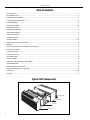
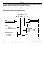
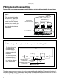
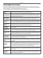
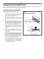
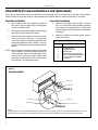
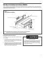
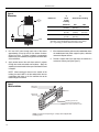
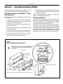
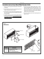
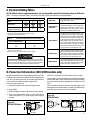
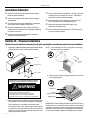
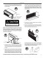
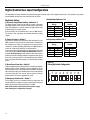
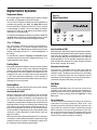
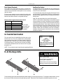
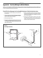
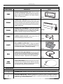
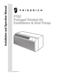
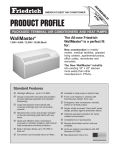
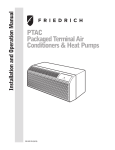
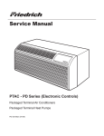
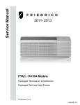
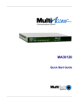
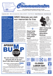
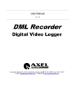
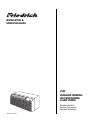
INSTALLATION &
OPERATION GUIDE
PTAC
PACKAGED TERMINAL
AIR CONDITIONERS
& HEAT PUMPS
Standard Control
Remote Thermostat
Seacoast Protected
920-087-04 (3-05)
920-087-04 (3-05)
Table of Contents
Unit Components ...............................................................................................................................................................................................2
Model Number Code..........................................................................................................................................................................................3
Installation Recommendations ..........................................................................................................................................................................4
Friedrich Digital Control Features ................................................................................................................................................................. 5-6
Drain Kit Installation ........................................................................................................................................................................................7-8
Wall Sleeve Installation .................................................................................................................................................................................9-10
Deep Wall Installation ...................................................................................................................................................................................... 11
Standard Grille Installation .............................................................................................................................................................................. 12
Electrical Rating Tables ................................................................................................................................................................................... 13
Power Cord Information ................................................................................................................................................................................... 13
Installation Checklist ........................................................................................................................................................................................ 14
Chassis Installation .....................................................................................................................................................................................14-15
Digital Control User Input Configuration .........................................................................................................................................................16
Operation .......................................................................................................................................................................................................... 17
Remote Thermostat and Low Voltage Control Connections ......................................................................................................................... 18
Desk Control Terminals ................................................................................................................................................................................... 19
Auxiliary Fan Control........................................................................................................................................................................................19
Fresh Air Vent Control...................................................................................................................................................................................... 19
Air Discharge Grille ..........................................................................................................................................................................................19
Start-up Checklist.............................................................................................................................................................................................20
Appendix A: Electrical Wiring for 265 V Models............................................................................................................................................21
Routine Maintenance .......................................................................................................................................................................................22
Basic Troubleshooting Techniques .................................................................................................................................................................23
Digital Control Diagnostics and Test Mode ....................................................................................................................................................24
Accessories ................................................................................................................................................................................................ 25-26
Warranty ...........................................................................................................................................................................................................27
Typical Unit Components
Outdoor grille
Wall sleeve
Chassis
Front cover
2
920-087-04 (3-05)
Thank you for your decision to purchase the newly designed Friedrich Packaged Terminal Air Conditioner (PTAC). We are
confident that you will find this unit a quiet and efficient example of Friedrich reliability.
This Installation and Operation Manual has been designed to insure maximum satisfaction in the performance of your unit.
For years of trouble-free service, please follow the installation instructions closely. We cannot overemphasize the importance
of proper installation. We have added new information to the basic instructions to help you achieve success.
Remember, proper installation is not difficult but it is essential.
Model Number Code
PD H 07 K 3 S A 1
Engineering Digit
Series
PD = Friedrich Digital PTAC
System
X = Accessory
E = Cooling with or without
electric heat
H = Heat Pump with Auxiliary Heat
Design Series
Options
S = Standard
C = Seacoast Protection
Nominal Heater Size
(@ 230V or 265V)
3 = 3.4 KW
0 = No Heater
5 = 5.0 KW*
2 = 2.5 KW
* 5.0 kw only available on 12000 and 15000
Btu/h models
Nominal Cooling Capacity
07 = 7,000 Btuh
09 = 9,000 Btuh
12 = 12,000 Btuh
15 = 15,000 Btuh
Voltage
K = 230/208V - 1 Ph. - 60 Hz.
R = 265V - 1 Ph. - 60 Hz.
Please read this manual thoroughly prior to equipment installation or operation. It is the installer’s responsibility
to properly apply and install the equipment. Installation must be in conformance with the NFPA 70-2002 National
Electric Code or current edition and Uniform Mechanical Code current edition and applicable local or national codes.
3
920-087-04 (3-05)
PTAC Installation Recommendations
For proper PTAC unit performance and maximum operating life please refer to the minimum installation clearances below:
Figure 1
PTAC units should be installed
no closer than 12" apart when
two units are side by side. If
three of more PTAC units are to
operate next to one another allow
a minimum of 36" between units.
Also, a vertical clearance of 60"
should be maintained between
units installed.
THREE OR MORE PTACs
ADJACENT 36" MINIMUM
VIEW: OUTSIDE
BUILDING ELEVATION
TYP.
WINDOW
36"
TWO ADJACENT
PTACs 12" MINIMUM
60"
60" VERTICAL MIMUMUM
BETWEEN PTACs
GROUND FLOOR PTACs
6" MINIMUM FROM GRADE
12"
6"
Figure 2
For PTACs on the ground floor or anytime obstructions are present, use the following guidelines:
• For minor obstructions
such as lamp poles
or small shrubbery a
clearance of 12" from the
outdoor louver should be
maintained.
• For major obstructions
such as a solid fence, wall
or other heat rejecting
device like a condensing
unit, a minimum distance
of 36" should be kept.
TYP. BUILDING ( PLAN VIEW )
36"
36"
PTAC
PTAC
PTAC
12"
12" MINIMUM, MINOR
OBSTRUCTIONS
36" MIMUMUM, MAJOR
OBSTRUCTIONS
POLE
36"
SHRUB
FENCE OR WALL
CONDENSING UNIT
The above suggestions are for reference only and do not represent all possible installations. Please contact the factory for
information regarding affects of other installation arrangements. By following these simple recommendations you can be
confident that your Friedrich PTAC will provide years of worry free operation.
4
920-087-04 (3-05)
Friedrich Digital Control Features
The new Friedrich digital PTAC has state of the art features to improve guest comfort, indoor air quality and conserve energy.
Through the use of specifically designed control software for the PTAC industry Friedrich has accomplished what other Manufacturer’s have only attempted – a quiet, dependable, affordable and easy to use PTAC.
Below is a list of standard features on every Friedrich PTAC and their benefit to the owner.
Digital Temperature
Readout
By digitally monitoring desired room temperature the room is controlled more precisely than conventional systems. The large, easy
to read LED display can show either set-point or actual room temperature as selected by owner.
One-Touch Operation
When the unit is powered off the unit can be returned directly to heating or cooling mode by pressing the ‘Heat’ or ‘Cool’ buttons
without the confusing power up sequence of some controls. One-touch control takes guesswork out of unit control delivering a more
enjoyable experience and eliminating front-desk calls.
Individual Mode and
Fan Control Buttons
By having separate control buttons and indicators for both fan and mode settings the Friedrich digital control eliminates the confusion of previous digital PTACs. The accurate temperature setting provides greater guest comfort than other systems.
Quiet Start/Stop
Fan Delay
The fan start and stop delays prevent abrupt changes in room acoustics due to the compressor energizing or stopping immediately.
Upon call for cooling or heating the unit fan will run for five seconds prior to energizing the compressor. Also, the fan off delay allows
for “free cooling” by utilizing the already cool indoor coil to its maximum capacity by running for 30 seconds after the compressor.
Remote Thermostat
Operation
Some applications require the use of a wall mounted thermostat. All new Friedrich PTACs may be switched from unit control to
remote thermostat control easily without the need to order a special model or accessory kit.
Wireless Remote
Control Ready
Guests can adjust the temperature and mode of the unit through the use of an optional hand held wireless remote, improving guest
comfort and relaxation.
Internal Diagnostic
Program
The new Friedrich digital PTAC features a self diagnostic program that can alert maintenance to component failures or operating
problems. The internal diagnostic program saves properties valuable time when diagnosing running problems.
Service Error Code
Storage
The self diagnosis program will also store error codes in memory if certain conditions occur and correct themselves such as extreme high or low operating conditions or activation of the room freeze protection feature. Storing error codes can help properties
determine if the unit faced obscure conditions or if an error occurred and corrected itself.
Constant Comfort
Room Monitoring
The on-board processor monitors time between demand cycles (heat or cool) and will cycle the fan every 9 minutes to sample the
room condition and determine if the desired conditions are met. This allows the room to have similar benefits to a remote mounted
stat without the complication or cost of a wall mounted thermostat.
Electronic Temperature
Limiting
By limiting the operating range the property can save energy by eliminating “max cool” or “max heat” situations common with older
uncontrolled systems. The new electronic control allows owners to set operating ranges for both heating and cooling independently
of one another.
Room Freeze
Protection
When the PTAC senses that the indoor room temperature has fallen to 40°F the unit will cycle on high fan and the electric strip heat
to raise the room temperature to 46°F then cycle off again. This feature works regardless of the mode selected and can be turned
off. The control will also store the Room Freeze cycle in the service code memory for retrieval at a later date. This feature ensures
that unoccupied rooms do not reach freezing levels where damage can occur to plumbing and fixtures.
Random Compressor
Restart
Multiple compressors starting at once can often cause electrical overloads and premature unit failure. The random restart delay
eliminates multiple units from starting at once following a power outage or initial power up. The compressor delay will range from
180 to 240 seconds.
Digital Defrost
Thermostat
The new Friedrich PTAC uses a digital thermostat to accurately monitor the outdoor coil conditions to allow the heat pump to run
whenever conditions are correct. Running the PTAC in heat pump mode save energy and reduces operating costs. The digital
thermostat allows maximization of heat pump run time.
5
920-087-04 (3-05)
Friedrich Digital Control Features Continued
6
Instant Heat
Heat Pump Mode
Heat pump models will automatically run the electric heater to quickly bring the room up to temperature when initially energized,
then return to heat pump mode. This ensures that the room is brought up to temperature quickly without the usual delay associated with heat pump units.
Even Heat Monitoring
The digital control monitors indoor conditions to ensure that the room temperature is within five degrees of the setpoint. If necessary the unit will cycle the electric heat to maintain the temperature. This feature ensures guest comfort by delivering the heating
benefits of an electric heater while maintaining the efficiency benefits of a heat pump.
Fan Cycle Control
The owner may choose between fan cycling or fan continuous mode based on property preference. (Note: Even heat monitoring and quiet start/stop fan delay only operate in fan cycle mode) Fan continuous mode is used to keep constant airflow circulation in the room during all times the unit is ‘ON’. Fan cycle will conserve energy by only operating the fan while the compressor
or electric heater is operating.
Emergency Heat Override
In the event of a compressor failure in heat pump mode the compressor may be locked out to provide heat through the resistance heater. This feature ensures that even in the unlikely event of a compressor failure the room temperature can be maintained until the compressor can be serviced.
Desk Control Ready
All Friedrich digital PTACs have low voltage terminals ready to connect a desk control energy management system. Controlling the unit from a remote location like the front desk can reduce energy usage and requires no additional accessories at the
PTAC.
Indoor Coil Frost Sensor
The frost sensor protects the compressor from damage in the event that airflow is reduced or low outdoor temperatures cause
the indoor coil to freeze. When the indoor coil reaches 30°F the compressor is diabled and the fan continues to operate based
on demand. Once the coil temperature returns to 45°F the compressor returns to operation.
Ultra-Quiet Air System
The new Friedrich PD series units feature a indoor fan system design that reduces sound levels without lowering airflow and
preventing proper air circulation.
High Efficiency
The Friedrich PTAC benefits quality components and extensive development to ensure a quiet, efficient and dependable unit.
Single Motor
Friedrich’s single-motor design allows for enhanced outdoor airflow and simplifies the unit design without the need for redundant components.
Rotary Compressor
High efficiency rotary compressors are used on all Friedrich PTACs to maximize durability and efficiency.
Auxiliary Fan Ready
The Friedrich PTAC features a 24V AC terminal for connection to an auxiliary fan that may be used to transfer air to adjoining
rooms. Auxiliary fans can provide conditioning to multiple rooms without the requirement of multiple PTAC units.
Aluminum Endplates
All Friedrich PTACs are built with .04" endplates made from aluminum as opposed to steel. The endplates are typically the most
susceptible area for corrosion and aluminum is far more resistant to corrosion than even coated steel.
Seacoast Protection
Optional Seacoast protection is available to protect the outdoor coil from harsh environments. The Friedrich Seacoast process
includes dipping the entire outdoor coil in a 7-step coating process that provides superior protection to only coating the fins of
the coil.
Top Mounted Antimicrobial Air Filters
All Friedrich PTAC return air filters feature an anti-microbial element that has proven to prevent mold and bacterial growth in
laboratory testing. PDXFT replacement filter kits feature the same anti-microbial agent. All filters are washable and reusable
and are easily accessed from the top of the unit without the removal of the front cover.
Filtered Fresh Air Intake
Friedrich PTAC units are capable of introducing up to 70 CFM of outside air into the conditioned space. The outdoor air passes
through a washable mesh filter to prevent debris from entering the airstream.
920-087-04 (3-05)
Installation Instructions PXDR10 Drain Kit
NOTE: Determine whether drain will be located within the wall, on the indoor side, or will drain to the exterior of the building. Follow
appropriate instructions below depending on your particular type of installation.
Internal Drain (optional for new construction)
NOTE: If installing an internal drain, you MUST install a drain kit
on the wall sleeve before the wall sleeve is installed.
1.
Refer to Figure 3 below and locate the drain within the
"Primary" area for best drainage. Maintain at least a 1/2"
clearance from the embossed area.
2.
Using the mounting plate with the 1/2" hole as a template,
mark and drill two, 3/16" mounting holes and a 1/2" drain
hole.
3.
4.
Remove the backing from the gasket and mount it on the
flat side of the mounting plate. (See Figure 4.) Insert the
drain tube through the hole in the gasket and mounting
plate so the tube flange will be against the wall sleeve.
Figure 3
Drain Kit Location and Installation
Secondary area
Primary area - no foam insulation
If the drain must be located in the
secondary area, the foam insulation
must be cut away and removed to
allow access to the drain.
3"
7.6 cm
Position the assembly beneath the drilled holes and
secure it with #10-24 x 1/2" machine screws and lock
nuts provided. Seal the tops of the screws with silicone
caulking.
Wall sleeve
5.
Use 1/2" I.D. copper tube, PVC pipe, or vinyl hose (obtained
locally) to connect the internal drain tube to the drain system
in the building.
Gasket
Mounting plate
Nut
Drain tube
6.
Referring to Detail A on page 6, locate and assemble the
(2) two cover plates and gaskets over the drain holes at
the rear of the wall sleeve. Attach them with the #10 sheet
metal screws provided. Make certain that the four overflow
slots at the rear of the wall sleeve are not blocked (See
drawing of the back of the sleeve on page 6).
7.
If a deep wall extension (PXWE) is used, after installing
the field supplied flashing, caulk as required. Be sure to
caulk around the flashing and the wall sleeve where the
hole was drilled for the drain tube.
Screw
7
920-087-04 (3-05)
External Drain (for new construction or unit replacement)
When using an external drain system, the condensate is removed through either of two drain holes on the back of the wall sleeve.
Select the drain hole which best meets your drainage situation and install the drain kit. Seal off the other with a cover plate.
Drain Tube Installation
Cover Plate Installation
1.
Peel the backing tape off the gaskets and apply the
sticky side to one cover plate and one mounting plate
as shown in Details A and B.
2.
Place the drain tube through the gasket and the mounting
plate with the flange toward the wall sleeve.
3.
Attach the drain tube assembly to one of the two drain
holes at the rear of the wall sleeve. The large flange
on the mounting plate is positioned at the bottom of the
sleeve facing toward the sleeve, Detail B. When the
drain tube is positioned at the desired angle, tighten the
screws.
NOTE: If the wall sleeve has not been installed, the drain tube
must be rotated to a horizontal position until after the
sleeve is installed. Tighten the mounting plate screws
when the tube is in the proper position. Make certain
that the four overflow slots at the rear of the wall sleeve
are not blocked. (See the drawing below.)
4.
Mount the foam gasket to the cover plate. Using two
#10 x 1/2" sheet metal screws (provided), attach the
cover plate to the remaining drain hole. Make certain
the large flange on the plate is positioned at the bottom
of the sleeve.
5.
Discard the additional cover plate, gasket, machine
screws, and locknuts.
PXDR1O
QUANTITY
2
1
1
3
4
2
2
DESCRIPTION
COVER PLATES
MOUNTING PLATE
DRAIN TUBE
MOUNTING PLATE GASKETS
#10 X 1/2" MOUNTING SCREWS
10-24 X 1/2" MACH. SCREWS
LOCKNUTS
Figure 4
Drain Kit Installation
Foam gasket
Mounting plate
DETAIL A
1
Foam gasket
/2" O.D. tube
Mounting plate
#10 sheet metal screws
DETAIL B
NOTES:
The large flange on the mounting plate is positioned at the bottom of the sleeve facing toward the sleeve. The drain tube must be rotated to a horizontal
position to allow for the wall sleeve to be installed into the wall. Once the wall sleeve is installed, return the drain tube to a downward angle.
8
920-087-04 (3-05)
Wall Sleeve Installation Instructions (PDXWS)
NOTE: Insure that the unit is only installed in a wall structurally adequate to support the unit including the sleeve, chassis and accessories.
If the sleeve projects more than 8" into the room, a subbase or other means of support MUST be used. Please read these instructions
completely before attempting installation.
Figure 5
Typical Wall Sleeve Installation
in.
¼" m
42 cm)
3
7.
Lintel to support masonry walls
16¼"
(41.3 cm)
(10
27
Electrical receptacle
i
)m
n.
cm
(1
0"
5
Insulation
10"
(25.4 cm)
max.
1
(34 3¾"
.9 c
m)
Electrical receptacle
Wall opening
Wall sleeve
Insulation
Smooth side of screw
clip facing into room
Note: All 230/208V units are manufactured with a 60" power cord. The receptacle
locations above must be followed to ensure proper connections.
For Deep Wall Installation See Section II
The following instructions apply ONLY to walls less than
13 1/4" in depth.
1.
From inside the building, position the wall sleeve in the
opening and push it through the wall so it protrudes at least
1/4" on the outside, note Figure 5.
2.
Position the wall sleeve with a slight tilt towards the outside
to facilitate condensate drainage. It should be level side-toside and the front should be 1/4 bubble higher than the back.
DO NOT allow any pitch toward the inside.
Electrical shock hazard.
Turn electric power OFF at the fuse box or service panel
before making any electrical connections and ensure a
proper ground connection is made before connecting line
voltage. Failure to do so can result in property damage,
personal injury and/or death.
9
920-087-04 (3-05)
Figure 6
Dimensions
¼"
(6.4 cm)
min.
A
Dimension*
3.
4.
Drill two 3/16" holes through each side of the sleeve
approximately 4" from top and 4" from bottom of sleeve.
Screw four #10 x 1" screws (included) or appropriate
fasteners for your installation, through the holes in the sides
of the wall sleeve.
Allow
for wall
finishing
Allow for floor finishing
Min.
Max
¼"
(6.4 mm)*
¼"
(6.4 mm)
---
With Subbase
1¾"
(4.5 cm)
3½"
(8.9cm)
5"
(12.7cm)
With Lateral Duct
¾"
(1.9 cm)
¼"
(6.4 mm)
---
B
Wall
B
(Minimum)
No Accessories
13¾ "
(35 cm)
A
* If more than one accessory is to be used, use the maximum
dimension. If the wall thickness is more than 13¾" (35cm) (A + ¼" [6.4 mm]), a sleeve extension must be used.
5.
If the chassis and exterior grille are to be installed later, leave
the weatherboard and center support in place, otherwise
remove and dispose of them.
6.
Provide a support lintel if the wall sleeve is installed in a
concrete or masonry wall. (See Figure 7.)
Apply sealant around the wall sleeve where it projects
through the inside and outside wall surfaces. Apply the
sealant to the screw heads or the tops of the fasteners used
in Step #3.
NOTE: When sealing the sleeve on the outside of the
building, be careful NOT to let the sealant block the two
condensate drain holes or the four overflow slots at the
bottom flange of the sleeve.
Figure 7
Lintel Installation
Main studs
Jack studs
Lintel
Main studs
Jack studs
Mounting screw holes
No holes in bottom of wall
sleeve unless drain kit is used
NOTE: Construct wall opening to comply with all applicable
building codes.
10
920-087-04 (3-05)
Section II — Deep Wall Installation (PXWE)
If the wall is thicker than allowed in the notes in Figure 6, a sheet
metal wall sleeve extension and flashing MUST be used.
6. Condensate notches and overflow slots must be kept clear
of sealant and gaskets so condensate can flow freely into
the wall sleeve extension.
Installation Instructions for the PXWE – 4" Wall
Sleeve Extension
NOTE: Improper fabrication or installation of a wall sleeve
extension will impair PTAC performance.
The following points MUST be considered when installing a wall
sleeve extension:
Extension Installation
1 Provision must be made to direct excess condensate from
the back of the wall sleeve into the extension then outside
the building or to a drainage system.
2. Air baffles must be mounted to properly direct air flow to
and from the condenser.
3. The wall sleeve extension design must allow for the proper
mounting of the grille.
4. Caulking is required at all sites where condensate or
external water could potentially infiltrate into the building.
Secure the wall sleeve extension to the wall sleeve before
installing it in the wall. Refer to Figure 8 for a guide for fabrication
of a condensate drip panel. The panel MUST extend the full depth
of the wall sleeve and the wall sleeve extension.
Pay particular care in sealing and caulking the panel where it
makes contact with the wall sleeve (see Figure 8). After installation
in the wall, secure with fasteners through the sides. Use a good
grade of silicone sealant around the sleeve extension. Seal all
exposed screw heads. When the installation is complete, the
outside grille should be attached to the wall sleeve extension.
5. Fabricate and install metal flashing in wall to serve as a drip
panel. Refer to drawing for more information.
Figure 8
Wall Sleeve Extension Sealant Locations
IMPORTANT NOTE: The silicone bead MUST extend 3"
up the side of the two flanges to prevent condensate
from leaking.
Wall Sleeve
Outside Edge
Insulation
Air Baffles
Sealant inside (4) bottom corners
Width of Wall
Drip
Edge
Condensate
Drip Panel
(Field
Supplied)
Condensate
Notches (4)
Wall Sleeve Extension, 42" X 16" Frame, 20 gauge minimum, painted or aluminium
PXWE Wall Sleeve
Extension
11
920-087-04 (3-05)
Installation Instructions Model PXGA Standard Grille
1. Remove the center support and weatherboard if still installed
in the sleeve.
2. Insert six plastic grommets into the grille openings from the
outside of the grille as shown in Figure 9.
3. Insert two #8 x 3/8" sheet metal screws (provided) in the top
two outside edge plastic grommets, and tighten them half way
into the grommets.
5. Grasp the grille by the attached plastic handles. Position
it with the condensate drain knockouts facing down. From
inside the building, maneuver the grille through the wall
sleeve and pull toward you until the screw heads are
inserted into the keyhole slots at the top of the wall sleeve.
Tighten the two screws completely.
6. Insert the remaining screws into the remaining holes and
tighten securely.
4. CAUTION: Bodily injury can be caused by grilles falling from
a building during installation. It is recommended that a safety
line be attached to the grille and an anchor point inside the
building during installation.
Figure 9
Standard Grille
Wall sleeve
Weatherboard
Center support
PXGA Standard Grille
Description
Quantity
1
6
6
12
Stamped Aluminum Grille
Plastic Grommets
#8 x /8" Sheet Metal Screws
3
Plastic handles
Plastic
grommets
920-087-04 (3-05)
A. Electrical Rating Tables
All 230/208 volt units are equipped with power cords. See Appendix B on page 19 for wiring instructions on 265V units.
NOTE: Use Copper Conductors ONLY. Wire sizes are per NEC, check local codes for overseas applications.
Table 1
250 V Receptacles and Fuse Types
AMPS
15
20*
30
WIRE SIZE
Use ONLY wiring size recommended for
single outlet branch circuit.
FUSE/CIRCUIT
BREAKER
Use ONLY type and size fuse or HACR circuit breaker indicated on unit’s rating plate.
Proper current protection to the unit is the
responsibility of the owner. NOTE: A time
delay fuse is provided with 265V units.
GROUNDING
Unit MUST be grounded from branch circuit
through service cord to unit, or through separate ground wire provided on permanently
connected units. Be sure that branch circuit
or general purpose outlet is grounded. The
field supplied outlet must match plug on
service cord and be within reach of service
cord. Refer to Table 1 for proper receptacle
and fuse type. Do NOT alter the service cord
or plug. Do NOT use an extension cord.
RECEPTACLE
The field supplied outlet must match plug on
service cord and be within reach of service
cord. Refer to Table 1 for proper receptacle
and fuse type. Do NOT alter the service cord
or plug. Do NOT use an extension cord.
WIRE SIZING
Use recommended wire size given in Table
2 and install a single branch circuit. All wiring
must comply with local and national codes.
NOTE: Use copper conductors only.
RECEPTACLE
TIME-DELAY TYPE FUSE
(or HACR circuit breaker)
15
20
30
HACR – Heating, Air Conditioning, Refrigeration
* May be used for 15 Amp applications if fused for 15 Amp
NOTE: 265 volt units are hard wired.
Table 2
Recommended branch circuit wire sizes*
NAMEPLATE / MAXIMUM
CIRCUIT BREAKER SIZE
AWG WIRE SIZE**
15
20
30
14
12
10
AWG – American Wire Gauge
* Single circuit from main box
** Based on copper wire, single insulated conductor at 60°C
ELECTRIC SHOCK HAZARD! Turn off electric power before service or installation.
All electrical connections and wiring MUST be installed by a qualified electrician and
conform to the National Electrical Code and all local codes which have jurisdiction.
Failure to do so can result in property damage, personal injury and/or death.
B. Power Cord Information (230/208V models only)
All Friedrich 230/208V PTAC units are shipped from the factory with
a Leakage Current Detection Interrupter (LCDI) equipped power
cord. The LCDI device meets the UL and NEC requirements for
cord connected air conditioners effective August 2004.
To test your power supply cord:
1. Plug power supply cord into a grounded 3 prong outlet.
2. Press RESET.
NOTE: The LCDI device is not intended to be used as a switch.
Once plugged in the unit will operate normally without the need to
reset the LCDI device. If the LCDI device trips and requires resetting
the cause of the trip should be identified prior to further use of the
PTAC.
If the device fails to trip when tested or if the power supply cord is
damaged it must be replaced with a new supply cord obtained from
the product manufacturer, and must not be repaired.
3. Press TEST (listen for click; Reset button trips and pops out).
4. Press and release RESET (listen for click; Reset button
latches and remains in). The power supply cord is ready for
operation.
Figure 10b
30A LCDI Device
7"
4.1"
Figure 10a
2"
TEST
2"
RESET
15/20A LCDI Device
Test Button
Reset Button
Test Button
Reset Button
13
920-087-04 (3-05)
Installation Checklist
Inspect all components and accessories for damage
before and after installation.
Remove the cardboard wall sleeve support and grille
weatherboard.
Check for proper wall sleeve installation in accordance
with the wall sleeve installation instructions.
Check for a subbase kit or other means of structural
support which is required for ALL installations projecting
more than 8" into room.
Ensure that the chassis is installed in a 16" high x 42" wide
wall sleeve that is no deeper than 13 3/4". A baffle kit is
required if the sleeve exceeds that depth.
Ensure that drapes, bed, bedspread, furniture, etc. DO
NOT block either return or discharge air grilles.
Inspect the condenser air inlet and outlet for any
obstructions (shrubbery, etc.)
Ensure that 'reset' button is pressed on LCD device (only
on cord connected models)
Install the recommended Condensate Drain Kits for
complete condensate removal.
Section III – Chassis Installation
Check to be sure the wall sleeve, extension (if used), grille, and drain kit are installed properly before chassis installation.
1. Remove the weatherboard and center support from the sleeve
(if still in place). Be sure an outdoor grille is attached.
NOTE: To avoid breaking the door or hinge pins, do not apply
excessive force when installing
2
1
Pins
Wall sleeve
Control
Door
Weatherboard
Front Panel
Center support
3. Remove the two chassis shipping brackets from the ends
of the shipping pallet.
IMPORTANT: Use a wall sleeve adapter kit (PXSE) if
installing a P-Series chassis in a T-Series sleeve.
3
Compressor
Suffocation hazard
Keep bag away from babies and children.
Do NOT use in cribs, beds or playpens. Destroy
immediately after opening. This bag is NOT a toy.
Failure to do so can result in personal injury and/or death
Chassis
shipping bracket
Shipping pallet
2. Remove the front cover contained in a protective plastic bag
from chassis. Remove the bag and dispose of it properly.
If the control door is not installed, follow these steps:
•
14
From the front of the cover, slide the right control door pin
into the hole on the right side of the front cover. Slide the
left door pin into the hole on the left side of the front cover
opening and snap it into place.
IMPORTANT: When installing a Friedrich P-Series PTAC into an
existing sleeve, it is important to ensure that the unit is installed
completely. Inspection of the air seal between the condenser air
baffles and around the indoor mounting flange is recommended.
In some cases additional gaskets or baffling may be required.
920-087-04 (3-05)
4. Center the chassis in the pre-installed sleeve and carefully
push the chassis until the chassis flange and gasket contact
the sleeve flange.
4
them into the quick nuts located on the chassis to secure
the cover. If the unit has been placed such that there is no
room to insert the thumbscrews from the bottom, request a
Side Mounting kit (Part No. PXSM) from Friedrich. Locate
the service cord or conduit in the notch at the bottom right
of the front cover.
6
Wall sleeve
Wall sleeve flange
Chassis flange
and gasket
7. If the filters are not already installed in tracks in the plastic
cover, slide them into place.
Copper refrigerant tubes are NOT handles.
Do NOT use tubing to lift or move chassis.
NOTE: If the unit is mounted flush to the floor, the service cord
MUST be rerouted at the bottom of the front cover on the side
closest to the receptacle. A notch MUST be made in the front
cover side where the cord exits the unit. It is the responsibility of
the installer to create an exit notch. See diagram 8 for suggested
opening size and placement.
8. Plug the cord (if applicable) into the appropriate receptacle.
Extra cord may be coiled inside the front cover behind the
return air grille. Restore power to the unit.
7
5
Screw clips
Chassis
mounting screw
Chassis
flange
5. Locate the four #10 x 1" chassis mounting screws. Tighten
the screws into the clips - adjacent to the alignment dimples
on the mounting brackets on the wall sleeve flange (two
per side).
6. Install the front cover assembly (including the discharge
grille) by placing the top of the cover onto the 90° angle
bracket along the top of the chassis. Rotate the bottom into
place and insert the included thumb screws into the slots
located at the bottom back corners of the cover. Tighten
To remove the front cover, remove the thumbscrews
at the bottom back corners of the cover (or sides).
Pull the bottom end forward and lift it up to clear the
L bracket across the top of the chassis.
8
Not to scale
If a remote thermostat is to be installed, proceed to page 18, Step 1. For a 265 V unit, proceed to Appendix A, Step 1.
15
920-087-04 (3-05)
Digital Control User Input Configuration
The adjustable control dip switches are located at the lower left hand portion of the digital Smart Center. The inputs are only visible
and accessible with the front cover removed from the PTAC.
Dip Switch Setting
1) Electronic Temperature Limiting – Switches 1-4
The digital control is set from the factory to allow a temperature range between 60°F and 90°F in both heating and cooling
mode. Dip Switches 1-4 can be used to set high and low limits
for either heating or cooling or both.
From the factory all four switches are in the up ‘ON’ position.
The charts to the right show the available electronic limiting
ranges.
2) Fan Cycle Control – Switch 5
All PTACs are shipped from the factory with Dip Switch 5 in the
‘OFF’ position to cycle the fan only when there is a demand for
the compressor or heater. As an option the fan may be set to
‘continuous’ mode by switching Dip Switch 5 to ‘ON’ position to
run the fan continuously while the unit is powered on.
To ensure that the room temperature is maintained evenly while
in fan cycle mode the Even Temp Load Anticipation feature is
enabled. Quiet Fan Delay is also enabled in fan cycle mode to
lessen the acoustical change between compressor start up and
shut off by running the fan for 5 seconds before each demand
cycle, and 30 seconds after cooling or 15 seconds after heating
cycles.
3) Room Freeze Protection – Switch 6
Units are shipped from the factory with the room freeze protection
disabled. Room Freeze Protection can be switched on at the
owner’s preference by moving Dip Switch 6 to ‘ON’. This feature
will monitor the indoor room conditions and in the event that the
room falls below 40°F the unit will cycle on high fan with the
electric heater. This occurs regardless of mode.
4) Emergency Heat Override – Switch 7
In the unlikely event of a compressor failure a heat pump unit
may be switched to operate in only the electric heat mode until
repairs can be made. Moving Dip Switch 7 to ‘ON’.
Note: PTAC must be disconnected from power supply
when making any configuration changes.
16
Heating Range Switches 1 & 2
Temperature
Range
Low
60
60
60
60
High
90
87
84
81
Dip
Switch
1
On
Off
Off
On
2
On
On
Off
Off
Cooling Range Switches 3 & 4
Temperature
Range
Low
60
63
66
69
High
90
90
90
90
Dip
Switch
3
On
On
Off
Off
4
On
Off
Off
On
Figure 11
Factory Dip Switch Configuration
O 1 2 3 4 5 6 7 8
N
920-087-04 (3-05)
Digital Control Operation
Temperature Display
Figure 12
The Friedrich digital PTAC is shipped from the factory to display
the desired room temperature on the LED readout.
Digital Control Panel
The unit can be configured to display the room temperature by
simultaneously pressing the ‘Cool’ and ‘High Fan’ buttons
for three seconds the display will show an ‘R’ for one seconds
to acknowledge the change. The unit will display the setpoint
whenever the ‘Temp’
or
buttons are pressed and then
switch back to room temperature.
To revert back to displaying the setpoint only press the ‘Cool’ and
‘Low Fan’ buttons for three seconds simultaneously, the unit will
display an ‘S’ for one seconds to acknowledge the change.
ºF vs. ºC Display
The unit is factory configured to display all temperatures in
degrees Fahrenheit (º F). To switch to degrees Celsius press
the ‘Fan Only’ and ‘Low Fan’ buttons simultaneously for three
seconds. The display will show a ‘C’ as acknowledgement of
the change.
To revert back to º F press the ‘Fan Only’ and ‘Low Fan’ buttons
simultaneously for three seconds. The display will show an ‘F’ as
acknowledgement of the change.
Cooling Mode
Pressing the ‘Cool’ button while the unit is in any mode, including
off, will put the unit into cooling mode. Adjust the temperature
readout to the desired room temperature and the unit will cycle
the compressor on and off to maintain a comfortable room. The
compressor will come on anytime that the room temperature
is 1.8°F above the desired temperature. The fan operation is
dependent on the fan mode selected, either continuous or cycling.
See page 16 for fan cycle control.
Heating Mode
Pressing the ‘Heat’ button while the unit is in any mode, including
off, will put the unit into heating mode.
Heat Pump Models (PDH)
When the ‘Heat’ button is pressed initially the unit will energize
the electric resistance heat to quickly bring the room to the
set temperature. When the desired room temperature falls
1.8°F below the desired set temperature the unit will cycle the
compressor on and operate as a heat pump to maintain the room
temperature while running more efficiently than resistance heat
only models. If the room temperature should fall more than 5°F
from the set temperature the unit will run the resistance heater.
The fan operation is dependent on the fan mode selected, either
continuous or cycling. Dip switch 5 controls the fan mode, see
page 16 for setting.
When the outdoor coil temperature falls below 30°F for more than
2 minutes the unit will operate the resistance heaters and not the
compressor. When the outdoor coil temperature reaches 45°F
the compressor will be allowed to operate again.
Heat/Cool Models (PDE)
After pressing the ‘Heat’ button, adjust the temperature readout to
the desired room temperature and the unit will cycle the resistance
heat on and off to maintain a comfortable room. The heater will
come on anytime that the room temperature is 1.8°F below the
desired temperature. The fan operation is dependent on the fan
mode selected, either continuous or cycling. Dip switch 5 controls
the fan mode, see page 16 for setting.
Emergency Heat Operation
In the event of a compressor failure in heat pump mode the
compressor may be locked out to provide heat through the
resistance heater. This feature ensures that even in the unlikely
event of a compressor failure the room temperature can be
maintained until the compressor can be serviced. Dip switch 7
controls the emergency heat setting, see page 16.
Fan Mode
Fan Only
Pressing the ‘Fan Only’ button will run the fan to allow for air
circulation in the room without operating the compressor or
heater regardless of the room or set temperature. The fan speed
selection is made by pressing either the ‘High Fan’ or ‘Low
Fan’ button.
Cycle/Continuous
The owner may choose between fan cycling or fan continuous
mode based on property preference. (Note: Even heat
monitoring and quiet start/stop fan delay only operate in fan
cycle mode) Fan continuous mode is used to keep constant
airflow circulation in the room during all times the unit is ‘ON’.
Fan cycle will conserve energy by only operating the fan while
the compressor or electric heater is operating. Dip switch 5
controls the fan mode, see page 16 for setting.
17
920-087-04 (3-05)
Remote Thermostat and Low Voltage Control Connections
Remote Thermostat
All Friedrich PD model PTAC units are factory configured to be
controlled by either the chassis mounted Smart Center or a 24V
single stage remote wall mounted thermostat. The thermostat
may be auto or manual changeover as long as the control
configuration matches that of the PTAC unit.
Note: To revert back to the Smart Center control of the unit replace
the jumper wire between the ‘GL’ and ‘GH’ terminals that was
removed in step 1.
Thermostat Connections
C
W
Y
R
GL
GH
B
To control the unit with a wall mounted thermostat follow
the steps below:
1) With the front cover removed locate the low voltage terminal
strip at the lower portion of the Smart Center.
2) Remove the jumper between the ‘GL’ and GH’ terminals.
3) The control is now configured for control by a wall thermostat. The Smart Center will no longer control the unit.
=
=
=
=
=
=
=
*If only one G terminal is present on thermostat connect to GL
for low fan or to GH for high fan operation.
4) If desired the accessory escutcheon kit (PDXRT) is to be
used, install it over the existing control panel.
Figure 13
Control board with optional PDXRT escutcheon kit installed
ON
DIP
JP1
1 2 3 4 5 6 7 8
18
R
Y
W
B
GL GH
Common Ground
Call for Heating
Call for Cooling
24V Power from Unit
Call for Low Fan
Call for High Fan
Reversing Valve Energized in heating mode
(PDH Models Only)
C
D1
D2
F1
F2
920-087-04 (3-05)
Desk Control Terminals
Auxiliary Fan Control
The Friedrich PD model PTAC has built-in provisions for
connection to an external switch to control power to the unit. The
switch can be a central desk control system or even a normally
open door switch.
The Smart Center also has the ability to control a 24VAC relay
to activate an auxiliary, or transfer, fan. The outputs are listed as
F1 and F2 on the control board.
For desk control operation connect one side of the switch to the
D1 terminal and the other to the D2 terminal (See figure 13).
Whenever the switch closes the unit operation will stop.
To connect the relay, simply wire one side of the relay to F1 and
the other side to F2. Anytime that the PTAC fan runs the terminals
will send a 24VAC signal to the relay. The relay must be 24 VAC,
50mA or less.
Note: The relay and auxiliary fans must be field supplied.
Maximum Wire Length for Desk Control Switch
Wire Size
Maximum Length
#24
#22
#20
#18
#16
400 ft.
600 ft.
900 ft.
1500 ft.
2000 ft.
Note: The desk
control system and
switches must be
field supplied.
NOTE: It is the installer's responsibility to ensure that all control
wiring connections are made in accordance with the installation
instructions. Improper connection of the thermostat control wiring
and/or tampering with the unit's internal wiring can void the
equipment warranty and may result in property damage, personal
injury or death. Other manufacturer's PTACs and even older
Friedrich models may have different control wire connections.
Questions concerning proper connections to the unit should be
directed to the factory.
G. Fresh Air Vent Control
The vent control lever is located behind the front cover on the
left side of the unit. The unit is shipped in the closed position
with a locking screw in place. The screw must be removed to
operate the lever. When the lever is back, (OPEN), outside air
is mixed with indoor air. When the lever is forward, (CLOSED),
no outside air is admitted into the room and room air is recycled
through the unit.
NOTE: The vent should remain closed for peak operating efficiency.
H. Air Discharge Grille
Moving parts hazard.
Turn off electric power before
servicing this component.
Failure to do so can result in property
damage, personal injury and/or death.
The air discharge grille can be redirected to blow air either straight up or at an angle into the room. To change the airflow direction, remove
the front cover, locate and remove the six grill retaining screws. Reverse the ends of the grille and refasten the grille to the cover.
19
920-087-04 (3-05)
I. Start-up Checklist
Inspect all components and accessories for
damage before and after installation.
Check installation for compliance with all national
and local codes and ordinances.
Read and follow all manufacturer's installation
instructions.
Check that circuit breaker(s) and electrical wire
sizes are correct. If the unit is supplied with a
power supply cord, insure that it is stored properly.
Check the condensate water drain outlet(s) to
make sure they are in compliance with all national
and local codes, that they are adequate for the
removal of condensate water, and that they meet
the approval of the end user.
Strictly follow installation instructions concerning
clearances around the unit.
Secure components and accessories, such as the
control door and front cover.
Check the unit air filter, condenser coil and
evaporator coil for any obstructions.
Check for proper operation of all components.
Instruct the owner or operator of the units
operation, and the manufacturer's
recommended routine maintenance schedule.
NOTE: It is highly recommended that a maintenance
schedule log book be prepared for recording
the dates and times of service.
Operate the unit for twenty minutes. Record
the unit's indoor/outdoor intake and discharge
temperatures, amperage draw, and power voltage.
Assemble the Warranty Certificate, the Operation
and Installation Manual, all accessory installation
instructions and the name, address and telephone
number of the Authorized Friedrich Warranty
Service Company in the area for the owner or
operator.
NOTE: Units are to be installed, inspected, and checked by qualified service personnel only.
20
920-087-04 (3-05)
Appendix A: Electrical Wiring for 265 Volt Models
NOTE: It is recommended that the PXSB subbase assembly, the PXCJ conduit kit and the PXDS disconnect switch be installed on all
hardwired units. If installing a flush-floor mounted unit, make provisions for all the line voltage power leads and conduit to be removed
for ease of maintenance and service to the chassis.
To install the line voltage power leads and conduit to the chassis, follow the instructions below.
1. Remove the four control box retaining screws (A) and open
the control box.
2. Pull the chassis power lead wires (B) (located on the bottomright side of the control box) through the plastic bushing so
they are located inside the control box.
3. Remove the plastic bushing.
4. Route the line voltage power leads through the hole where
the plastic bushing was located, and secure its conduit (use
a 1/2" straight conduit connector, with the locknut on the
inside of the control box.)
5. Make the appropriate electrical connections within the
control box, then secure the box on the chassis. Detailed
instructions are included with the installation instructions
for the conduit kit (PXCJ).
6. Route the line voltage power conduit from the control
box straight down the right front to the bottom side of the
chassis. This will allow the front cover to be installed without
interference with the electrical conduit.
Figure 15
Line Voltage Connections
Inside back of control
panel cover.
Screws
Screws
Fuse holder
21
920-087-04 (3-05)
J. Routine Maintenance
NOTE: Units are to be inspected and serviced by qualified service personnel only.
3. Periodically (at least yearly or bi-yearly): inspect all control
components, both electrical and mechanical, as well as the
power supply. Use proper testing instruments (voltmeter,
ohmmeter, ammeter, wattmeter, etc.) to perform electrical
tests. Use an air conditioning or refrigeration thermometer
to check room, outdoor and coil operating temperatures.
Use a sling psychrometer to measure wet bulb temperatures
indoors and outdoors.
1. Clean the unit air intake filter at least every 300 to 350 hours
of operation. Clean the filters with a mild detergent in warm
water and allow to dry thoroughly before reinstalling.
2. The indoor coil (evaporator coil), the outdoor coil (condenser
coil) and base pan should be inspected periodically (yearly
or bi-yearly) and cleaned of all debris (lint, dirt, leaves, paper,
etc.). Clean the coils and base pan with a soft brush and
compressed air or vacuum. If using a pressure washer, be
careful not to bend the aluminium fin pack. Use a sweeping
up and down motion in the direction of the vertical aluminum
fin pack when pressure cleaning coils. Cover all electrical
components to protect them from water or spray.
4. Inspect the surrounding area (inside and outside) to ensure
that the units' clearances have not been compromised or
altered.
5. Inspect the sleeve and drain system periodically (at least
yearly or bi-yearly) and clean of all obstructions and debris.
Clean both areas with an antibacterial and antifungal
cleaner. Rinse both items thoroughly with water and ensure
that the drain outlets are operating correctly. Check the
sealant around the sleeve and reseal areas as needed.
Before reinstalling the chassis in the sleeve, inspect the
indoor blower housing, blower wheel, condenser fan blade,
and condenser shroud periodically (yearly or bi-yearly) and
clean of all debris (lint, dirt, mold, fungus, etc.) Clean the
blower housing area and blower wheel with an antibacterial
/ antifungal cleaner. Use a biodegradable cleaning agent
and degreaser on condenser fan and condenser shroud.
Use warm or cold water when rinsing these items. Allow
the unit to dry thoroughly, inspect all gasket material for
deterioration (replace as necessary), and then reinstall the
chassis in the sleeve.
6. Clean the front cover when needed. Use a mild detergent.
Wash and rinse with warm water. Allow them to dry
thoroughly before reinstalling them in the chassis.
NOTE: Do not use a caustic coil cleaning agent on coils
or base pan. Use a biodegradable cleaning agent and
degreaser.
Figure 16
Components
Condenser Gasket
Outdoor Grille
Condenser Fan Blade
Indoor Blower
Condenser Shroud
Discharge Air Grille
Filters
Indoor Blower
Housing
Gasket
Compressor
Basepan
Front Cover
Innerwall
Return Air
Grille
22
Control Panel
Evaporator Coil
Wall Sleeve
920-087-04 (3-05)
K. Basic Troubleshooting Techniques
Being familiar with the sequence of operation on Standard Controlled Operating Units or the operation of the Remote Thermostat
Controlled Units is important. The following questions and answers may help to identify performance problems.
Environmental Effects - Cooling Mode
Environmental Effects - Heating Mode
Is unit sized to room size area and heat load demand?
Is unit properly sized to room area and heat load demand?
The number of people in the room, number of electrical devices,
solar gains, etc. are all variable items that can affect proper
sizing of the unit. Friedrich recommends that you consult with
an applications engineer for proper sizing.
The number of people in the room, number of electrical devices,
solar gains, etc. are all variable items that can affect proper
sizing of the unit. Friedrich recommends that you consult with
an applications engineer for proper sizing.
Is the outdoor temperature 60°F or below?
Is the outdoor temperature 70°F or above?
The unit is designed for outdoor temperatures above 60°F.
The unit is designed for outdoor temperatures below 70°F.
Is the indoor temperature 60°F or below? Ambient indoor
temperatures of 60°F or below will take a longer period of run
time to heat the area. Long run times may indicate that the unit
is undersized.
Is the indoor temperature 80°F or above?
Ambient indoor temperatures of 80°F or above will take a longer
period of run time to cool down the area. Long run times may
indicate that the unit is undersized.
Has the room area been increased where the unit is located?
Is indoor humidity high?
This condition will cause the unit to operate longer to remove
humidity before noticing any cooling effect.
Has the heat load been increased by additional devices such
as computer equipment, or has the room area been increased
where the unit is located?
If conditions have changed, the unit may not be able to cool and
condition as effectively as previously planned.
If the area where the unit is located has been increased, the unit
may not provide adequate heat.
Insufficient Maintenance and Inspection
Installation errors are the most common cause of poor performance.
Please follow installation instructions carefully. If other problems
exist, see Maintenance and Inspection Troubleshooting Guide
below.
Maintenance and Inspection Troubleshooting Guide
CAUSE
RESULT
System is not serviced or inspected
regularly (semiannually or annually).
Can result in premature component failures, poor performance and
increased operating costs.
Air filters are not cleaned regularly and
become blocked with particles.
May result in poor cooling, icing and water problems as well as
component failures and increased operating costs.
Condenser coil not maintained
properly (blocked with particles).
Evaporator coil not maintained properly
(blocked with particles).
May result in poor cooling, component failures and increased costs.
May result in poor cooling, icing and water problems, and increased
operating costs.
Components that show signs of fatigue
- not replaced.
May result in multiple service calls, poor performance and
increased operating costs.
Condensate drains and drain lines not
maintained.
May result in water and odor problems.
23
920-087-04 (3-05)
Digital Control Diagnostics and Test Mode
Diagnostics
Test Mode
The Friedrich Smart Center continuously monitors the PTAC unit
operation and will store service codes if certain conditions are
witnessed. In some cases the unit may take action and shut the
unit off until conditions are corrected.
For service and diagnostic use only, the built-in timers and
delays on the PTAC may be bypassed by pressing the ‘Cool’
and ‘Low Fan’ buttons simultaneously for three seconds while
in any mode to enter the test mode. TE will be displayed when
entering test mode, and DE will be displayed when exiting. The
test mode will automatically be exited 30 minutes after entering it
or by pressing the ‘Cool’ and ‘Low Fan’ buttons simultaneously
for three seconds.
To access the error code menu press the ‘Heat’ and ‘High Fan’
buttons simultaneously for three seconds. If error codes are
present they will be displayed. If multiple codes exist you can
toggle between messages using the temp
button. To clear
all codes press the temp
button for three seconds while in
the error code mode. To exit without changing codes press the
‘Low Fan’ button.
The chart below lists the possible error codes and their description:
Error
Code
01
NOT USED
Action Taken by Unit
Possible Cause
NONE
02
An extreme low voltage condition
exists <198V for 230V units and
<239V for 265V units.
Shut down unit. Display Error code and flash.
Once voltage rises to normal level system power
is restored.
• Inadequate power supply
• Defective breaker
• Blown fuse
03
Return air thermistor sensor open
or short circuit
Set return air sensor = 75°F. Alternate flash set
point and error code. Leave unit running.
• Defective sensor
04
Indoor coil thermistor sensor open
Or short circuit
Set ID coil temp = 40°F. Alternate flash set point
and error code. Leave unit running.
• Defective sensor
05
Outdoor coil thermistor sensor
open Or short circuit
Set OD coil temp = 20°F. Alternate flash set point
and error code. Automatically change over to
Electric heat Mode only. Leave unit running.
• Defective sensor
•
•
•
•
Dirty coil
Fan motor failure
Restricted air flow
Non-condensables in
refrigeration system
Dirty filters
Dirty coil
Fan motor failure
Restricted airflow
Improper refrigerant charge
Restriction in refrigerant circuit
If O.D. coil Temperature > 175 Deg
F for 2 consecutive minutes. (Heat
Pump models only)
Alternate flash set point and error code. Shut unit
down for 5 minutes, then try again 2 times, if fails
the 3rd time, then shut down unit.
07
I.D coil temperature <30 Deg F for
2 consecutive minutes.
Alternate flash set point and error code. Continue
fan operation while the compressor is locked out
until the indoor coil thermistor reaches 45° F, and
then energize the compressor. However, compressor must still wait a lockout time of 180 to 240
seconds.
•
•
•
•
•
•
08
If unit cycles (Heat or Cool
demand)> 9 times per hour
Alternate flash set point and error code. Keep unit
running.
• Unit oversized
• Low load conditions
09
If unit cycles (Heat or Cool
demand)< 3 times per hour
Alternate flash set point and error code. Keep unit
running.
• Unit undersized
• High load conditions
10
Room Freeze Protection triggered
Alternate flash set point and error code. Keep unit
running.
• Room temperature fell below 40°F
06
24
Code Translation
920-087-04 (3-05)
Friedrich PTAC Accessories
NEW CONSTRUCTION ACCESSORIES
MODEL NUMBER
DESCRIPTION
PDXWS
WALL SLEEVE zinc coated steel is prepared in an eleven-step
process, then powder coated with a polyester finish and cured
in an oven for exceptional durability. The wall sleeve is insulated
for sound absorption and thermal efficiency.
16" High x 42" Wide x 13¾" Deep.
PHOTO
PDXWS
PXGA
GRILLE standard, stamped aluminium, anodized to resist
chalking and oxidation.
PXAA
PXDB
PXSC
ARCHITECTURAL GRILLES Consist of heavy-gauge
6063-T5 aluminum alloy:
PXAA– Clear, extruded aluminum
PXDB– Dark bronze acrylic enamel
PXSC– Also available in custom colors.
PXDB
CONDENSATE DRAIN KIT Attaches to the bottom of the wall
sleeve for internal draining of condensate or to the rear wall sleeve
flange for external draining. Recommended on all units to remove
excess condensate. Packaged in quantities of ten.
PXDR10
PXDR10
PXWE
DEEP WALL SLEEVE EXTENSION A four inch deep anodized
aluminium extension that attaches to the outside of the wall sleeve
when the wall is greater than eleven inches thick (9½" when a
subbase is used, 10 inches when a lateral duct is used).
PXWE
PXSB
RT2
DECORATIVE SUBBASE Provides unit support for walls less
than six inches thick. Includes leveling legs, side filler panels
and mounting brackets for electrical accessories. Accepts
circuit breaker, power disconnect switch, or conduit kit.
PXSB
DIGITAL REMOTE THERMOSTAT Digital elec tron ic
thermostat with "one touch" adjustment. Mounts to wall for
control of unit.
MODE
FAN
RT2
PDXRT
PDXRT – REMOTE THERMOSTAT ESCUTCHEON KIT
This kit contains 10 escutcheons that can be placed over
the factory control buttons when a remote wall mounted
thermostat is used. The escutcheon directs the guest to the
wall thermostat for operation and retains the LED window to
display error codes and diagnostic information.
PDXRT
25
920-087-04 (3-05)
ADDITIONAL ACCESSORIES
MODEL NUMBER
DESCRIPTION
PXSE
SLEEVE EXTENSION RETROFIT KIT G-90 zinc coated
steel, 2.4" sleeve extension attached to the room side of the
sleeve to allow for the installation of a P-Series Friedrich
PTAC in a T-Series sleeve.
PHOTO
PXSE
PDXDA
LATERAL DUCT ADAPTER Attaches to the PTAC/PTHP
unit and provides a transition to direct up to 35% of the total
CFM to a secondary room, either left or right of the unit. Kit
includes duct plenum with discharge grille and internal baffle,
adapter and end cap.
PDXDE
LATERAL DUCT EXTENSION A three foot insulated
plenum that attaches to the left or right side of the duct
adapter. The extension can be cut to length by the installer.
Maximum allowable straight extension is fifteen feet.
PXDL
CONTROL DOOR LOCK KIT Locks control door to
prevent tampering by unauthorized users
PDXDA
M
FR ade in
4548 U
321 SA
PXDL
PDXFT
REPLACEMENT FILTER PACK These are original
equipment return air filters. They are reusable and can be
cleaned by vacuuming, washing, or blowing out, and are sold
in convenient ten packs. (Two filters per chassis)
PDXFT
PXCJ
CONDUIT KIT WITH JUNCTION BOX Hard wire conduit kit
with junction box for 208/230V and 256V units (subbase not
required). Kit includes a means of quick disconnect for easy
removal of the chassis. *Required for 265V installations.
PXCJ
PXPC
15/20/30
POWER CORD RETROFIT Replaces LCDI power cord on 230V
models when unit is used with a subbase. PXPC15 is used with
15 amp 2.5 kW units. PXPC20 is used with 20 amp 3.4 kW
units. PXPC30 is used with 30 amp 5.0 kW units.
PXPC30
CHASSIS OPTIONS
DESIGNATOR
26
DESCRIPTION
S
STANDARD UNIT Standard PTAC/PTHP chassis. Can be 230/208V or 265V, electric or heat pump.
C
SEACOAST PROTECTION Additional protection for PTAC/PTHP units in a coastal or corrosive
environment. The entire outdoor coil is submerged in a specially formulated enamel coating, then ovencured for a tough, corrosion-resistant finish.
920-087-04 (3-05)
Friedrich Air Conditioning Company
P.O. Box 1540
San Antonio, TX 78295
210.357.4400
www.friedrich.com
PD-SERIES
PACKAGED TERMINAL AIR CONDITIONERS
LIMITED WARRANTY
SAVE THIS CERTIFICATE. It gives you specific rights, you may also have other rights which may vary from state to state and province to
province.
In the event that your unit needs servicing, contact your nearest authorized service center. If you do not know the nearest service center,
ask the company that installed your unit or contact us - see address and telephone number above. When requesting service: please have
the model and serial number from your unit readily available.
Unless specified otherwise herein, the following applies: PACKAGED TERMINAL AIR CONDITIONERS AND HEAT PUMPS
LIMITED WARRANTY - FIRST YEAR (Eighteen (18) Months from the original date of purchase or twelve (12) months from
installation). Any defect in the unit’s material or workmanship will be repaired or replaced free of charge by our authorized service center
during the normal working hours; and
LIMITED WARRANTY - SECOND THROUGH FIFTH YEAR (Sixty-six (66) months from the date of purchase) ON THE SEALED
REFRIGERATION SYSTEM. Any part of the sealed refrigeration system on the P-series that is defective in material or workmanship will be
repaired or replaced free of charge (excluding freight charges) by our authorized service center during normal working hours. The sealed
refrigeration system consists of the compressor, metering device, evaporator, condenser, reversing valve, check valve, and the
interconnecting tubing.
These warranties apply only while the unit remains at the original site and only to units installed inside the continental United
States, Alaska, Hawaii, Puerto Rico and Canada. The warranty applies only if the unit is installed and operated in accordance
with the printed instructions and in compliance with applicable local installation and building codes and good trade practices. For
international warranty information, contact the Friedrich Air Conditioning Company - International Division.
Reasonable proof must be presented to establish the original purchase date, otherwise the beginning date of this certificate will be
considered to be our shipment date plus sixty days. Replacement parts can be new or remanufactured. Replacement parts and labor are
only warranted for any unused portion of the unit’s warranty.
We will not be responsible for and the user will pay for:
1. Service calls to:
A) Instruct on unit operation. B) Replace house fuses or correct house wiring. C) Clean or replace air filters. D) Remove
the unit from inaccessible locations. E) Correct improper installations.
2. Parts or labor provided by anyone other than an authorized service center.
3. Damage caused by:
A) Accident, abuse, negligence, misuse, riot, fire, flood, or acts of God. B) Operating the unit where there is a corrosive
atmosphere containing chlorine, fluorine, or any damaging chemicals (other than in a normal residential environment). C)
Unauthorized alteration or repair of the unit, which in turn affects its stability or performance. D) Failing to provide proper
maintenance and service. E) Using other than a "Seacoast Protected" unit in a coastal environment. F) Using an
incorrect power source. G) Faulty installation or application of the unit.
We shall not be liable for any incidental, consequential, or special damages or expenses in connection with any use or failure of
this unit. We have not made and do not make any representation or warranty of fitness for a particular use or purpose and there
is no implied condition of fitness for a particular use or purpose. We make no expressed warranties except as stated in this
certificate. No one is authorized to change this certificate or to create for us any other obligation or liability in connection with
this unit. Any implied warranties shall last for one year after the original purchase date. Some states and provinces do not allow
limitations on how long an implied warranty or condition lasts, so the above limitations or exclusions may not apply to you. The provisions of
this warranty are in addition to and not a modification of or subtraction from the statutory warranties and other rights and remedies provided
by law.
In case of any questions regarding the provisions of this warranty, the English version will govern.
(12-04)
27
Friedrich Air Conditioning Co.
Post Office Box 1540 • San Antonio, Texas 78295-1540
4200 N. Pan Am Expressway • San Antonio, Texas 78218-5212
(210) 357-4400 • FAX (210) 357-4480
www.friedrich.com
Printed in the U.S.A.
920-087-04 (3-05)